Embed Size (px)
Citation preview
7
Wind Turbine Simulators
Hossein Madadi Kojabadi1 and Liuchen Chang2 1Sahand University of Technology
2University of New Brunswick 1Iran
2Canada
1. Introduction
Electricity generation using wind energy has been well recognized as environmentally friendly, socially beneficial, and economically competitive for many applications. Wind turbine simulators (WTS) are important equipments for developing wind energy conversion systems and are used to simulate wind turbine behavior in a controlled environment without reliance on natural wind resources, for the purpose of research and design into wind turbine drive trains, especially energy conversion systems. Wind turbine simulators can significantly improve the effectiveness and efficiency of research and design in wind energy conversion systems. The simulator can be used for research applications to drive an electrical generator in a similar way as a wind turbine, by reproducing the torque developed by a wind turbine for a given wind velocity. Also, it can be used as an educational tool to teach the behavior, operation and control of a wind turbine. Usually induction motor, separately excited DC motor and permanent magnet synchronous motor can be used to reproduce the static and dynamic characteristics of real wind turbines. In the past few years, there have been many studies on wind turbine simulators. Authors of (Nunes et al., 1993), (Battaiotto et al., 1996), (Rodriguez et al., 1998) and (Monfared et al., 2009) utilized separately excited dc motors with controlled armature current. (Nunes et al., 1993) presented a wind turbine simulator using the electromagnetic (EM) torque equation of a dc machine. The armature and the field circuits were controlled so that the dc machine generated the static characteristics of a constant pitch wind turbine. (Monfared et al., 2009) , (Rabelo, et al., 2005) and (Guangchen, et al., 2010) utilized separately excited dc motor to reproduce the static and dynamic characteristics of real wind turbines. The wind turbine simulator described in (Monfared et al., 2009) aims to reproduce the mechanical behavior of wind turbine rotor, drive train and a gear box under dynamic and static conditions. The reference for the torque developed by the wind turbine includes the gradient and tower shadow effects that result in pulsating torques. The larger inertia effect and the steady-state behavior of real wind turbine are also included in the paper. In (Nichita et al., 1998) a more general approach of WTS was presented by the application of a dc motor. In (Jian & xu, 1987) a microcomputer-controlled SCR-DC motor was used to supply the shaft torque. A dc machine, although is ideal from the standpoint of control, is, in general, bulky and expensive compare with an AC machine and it needs frequent maintenance due to its commutators and brushes. Inverter driven PMSM can also work like a real wind turbine (Weihao Hu, et al., 2009), (Xu, Ke, et al., 2007). The wind turbine simulator consists of a
www.intechopen.com
Wind Turbines
164
microcontroller, an intelligent power module inverter, a PMSM and a control desk on the computer. The control desk obtains the wind speed and calculates the theoretical torque of a real wind turbine by using the wind turbine characteristics and the rotation speed of PMSM. Then the output torque of the PMSM can be regulated by controlling the stator current and frequency. Hence, the inverter driven PMSM can work like a real wind turbine. Inverter driven IM can also reproduce the dynamic and static characteristics of real wind turbine (Madadi, et al., 2004), (Madadi, & Chang, 2005) and (Yun, et al., 2009). A control program is developed that obtains wind profiles and, by using turbine characteristics and rotation speed of induction motor(IM), calculates the theoretical shaft torque of a real wind turbine. Comparing with this torque value, the shaft torque of the IM is regulated accordingly by controlling stator current demand and frequency demand of the inverter. In this chapter, an IGBT inverter-controlled squirrel cage induction motor was used instead
of a dc motor as a WTS. A dc machine, although is ideal from the standpoint of control, is, in
general, bulky and expensive compare with an AC machine and it needs frequent
maintenance due to its commutators and brushes. This drive is controlled using the
measured shaft torque directly, instead of estimating it as conventional drives do. The
proposed structure for WTS is achieved in two closed loops of control: speed control and
torque control. In this chapter we present the working principles, structures, and test results
of wind turbine simulator.
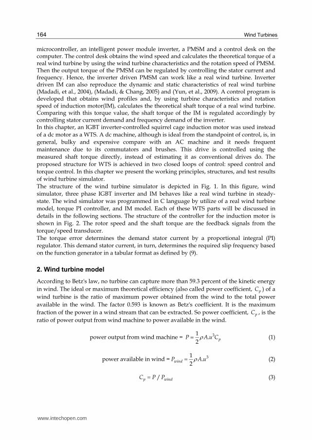
The structure of the wind turbine simulator is depicted in Fig. 1. In this figure, wind
simulator, three phase IGBT inverter and IM behaves like a real wind turbine in steady-
state. The wind simulator was programmed in C language by utilize of a real wind turbine
model, torque PI controller, and IM model. Each of these WTS parts will be discussed in
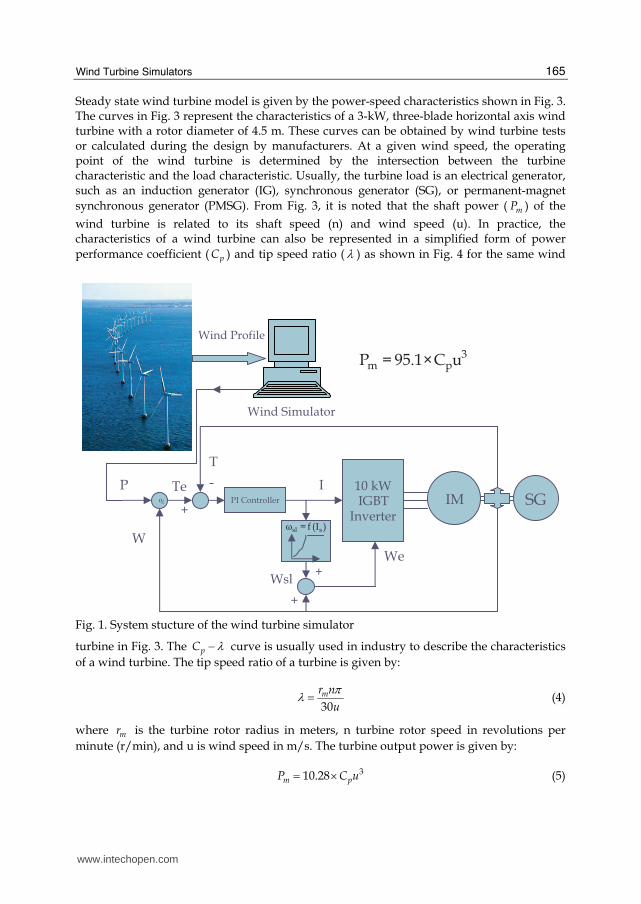
details in the following sections. The structure of the controller for the induction motor is
shown in Fig. 2. The rotor speed and the shaft torque are the feedback signals from the
torque/speed transducer.
The torque error determines the demand stator current by a proportional integral (PI)
regulator. This demand stator current, in turn, determines the required slip frequency based
on the function generator in a tabular format as defined by (9).
2. Wind turbine model
According to Betz's law, no turbine can capture more than 59.3 percent of the kinetic energy
in wind. The ideal or maximum theoretical efficiency (also called power coefficient, pC ) of a
wind turbine is the ratio of maximum power obtained from the wind to the total power
available in the wind. The factor 0.593 is known as Betz's coefficient. It is the maximum
fraction of the power in a wind stream that can be extracted. So power coefficient, pC , is the
ratio of power output from wind machine to power available in the wind.
power output from wind machine = 31.
2pP A u Cρ= (1)
power available in wind = 31.
2windP A uρ= (2)
/p windC P P= (3)
www.intechopen.com
Wind Turbine Simulators
165
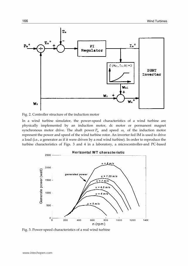
Steady state wind turbine model is given by the power-speed characteristics shown in Fig. 3. The curves in Fig. 3 represent the characteristics of a 3-kW, three-blade horizontal axis wind turbine with a rotor diameter of 4.5 m. These curves can be obtained by wind turbine tests or calculated during the design by manufacturers. At a given wind speed, the operating point of the wind turbine is determined by the intersection between the turbine characteristic and the load characteristic. Usually, the turbine load is an electrical generator, such as an induction generator (IG), synchronous generator (SG), or permanent-magnet
synchronous generator (PMSG). From Fig. 3, it is noted that the shaft power ( mP ) of the
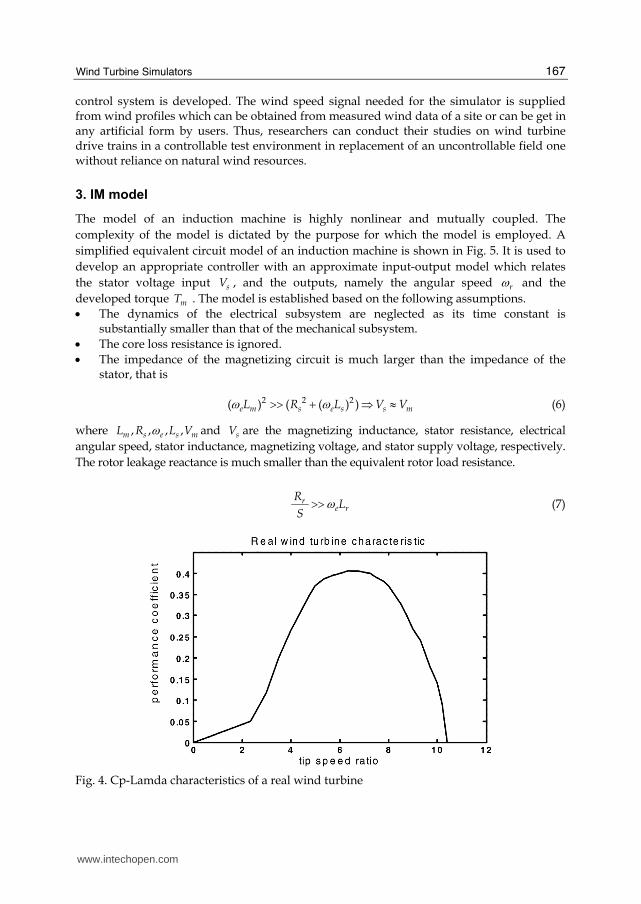
wind turbine is related to its shaft speed (n) and wind speed (u). In practice, the characteristics of a wind turbine can also be represented in a simplified form of power
performance coefficient ( pC ) and tip speed ratio ( λ ) as shown in Fig. 4 for the same wind
IM SG %
10 kW IGBT
Inverter
PI Controller
I
We
Wsl
W
P Te
T
-
+
+
+
Wind Simulator
Wind Profile
)I(f ssl =ω
3pm uC1.95P ×=
Fig. 1. System stucture of the wind turbine simulator
turbine in Fig. 3. The pC λ− curve is usually used in industry to describe the characteristics
of a wind turbine. The tip speed ratio of a turbine is given by:
30mr n
u
πλ = (4)
where mr is the turbine rotor radius in meters, n turbine rotor speed in revolutions per
minute (r/min), and u is wind speed in m/s. The turbine output power is given by:
310.28m pP C u= × (5)
www.intechopen.com
Wind Turbines
166
Fig. 2. Controller structure of the induction motor
In a wind turbine simulator, the power-speed characteristics of a wind turbine are
physically implemented by an induction motor, dc motor or permanent magnet
synchronous motor drive. The shaft power mP and speed rω of the induction motor
represent the power and speed of the wind turbine rotor. An inverter fed IM is used to drive
a load (i.e., a generator as if it were driven by a real wind turbine). In order to reproduce the
turbine characteristics of Figs. 3 and 4 in a laboratory, a microcontroller-and PC-based
Fig. 3. Power-speed characteristics of a real wind turbine
www.intechopen.com
Wind Turbine Simulators
167
control system is developed. The wind speed signal needed for the simulator is supplied from wind profiles which can be obtained from measured wind data of a site or can be get in any artificial form by users. Thus, researchers can conduct their studies on wind turbine drive trains in a controllable test environment in replacement of an uncontrollable field one without reliance on natural wind resources.
3. IM model
The model of an induction machine is highly nonlinear and mutually coupled. The
complexity of the model is dictated by the purpose for which the model is employed. A
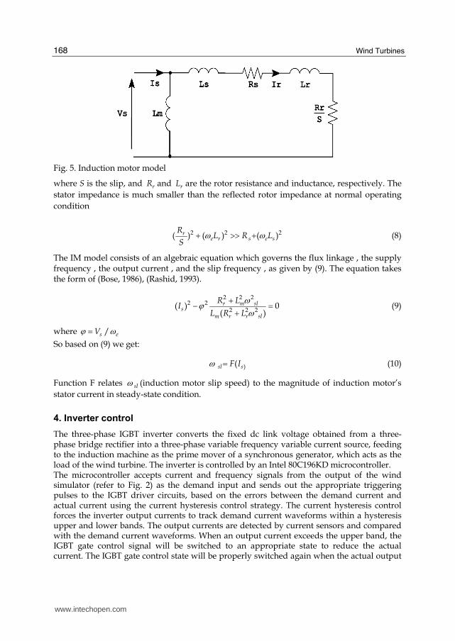
simplified equivalent circuit model of an induction machine is shown in Fig. 5. It is used to
develop an appropriate controller with an approximate input-output model which relates
the stator voltage input sV , and the outputs, namely the angular speed rω and the
developed torque mT . The model is established based on the following assumptions.
• The dynamics of the electrical subsystem are neglected as its time constant is substantially smaller than that of the mechanical subsystem.
• The core loss resistance is ignored.
• The impedance of the magnetizing circuit is much larger than the impedance of the stator, that is
2 2 2( ) ( ( ) )e m s e s s mL R L V Vω ω>> + ⇒ ≈ (6)
where , , , ,m s e s mL R L Vω and sV are the magnetizing inductance, stator resistance, electrical
angular speed, stator inductance, magnetizing voltage, and stator supply voltage, respectively.
The rotor leakage reactance is much smaller than the equivalent rotor load resistance.
re r
RL
Sω>> (7)
Fig. 4. Cp-Lamda characteristics of a real wind turbine
www.intechopen.com
Wind Turbines
168
Fig. 5. Induction motor model
where S is the slip, and rR and rL are the rotor resistance and inductance, respectively. The
stator impedance is much smaller than the reflected rotor impedance at normal operating
condition
2 2 2( ) ( ) ( )re r s e s
RL R L
Sω ω+ >> + (8)
The IM model consists of an algebraic equation which governs the flux linkage , the supply frequency , the output current , and the slip frequency , as given by (9). The equation takes the form of (Bose, 1986), (Rashid, 1993).
2 2 2
2 22 2 2
( ) 0( )r m sl
sm r r sl
R LI
L R L
ωϕ ω+− =+ (9)
where /s eVϕ ω=
So based on (9) we get:
)(sl sF Iω = (10)
Function F relates slω (induction motor slip speed) to the magnitude of induction motor’s
stator current in steady-state condition.
4. Inverter control
The three-phase IGBT inverter converts the fixed dc link voltage obtained from a three-phase bridge rectifier into a three-phase variable frequency variable current source, feeding to the induction machine as the prime mover of a synchronous generator, which acts as the load of the wind turbine. The inverter is controlled by an Intel 80C196KD microcontroller. The microcontroller accepts current and frequency signals from the output of the wind simulator (refer to Fig. 2) as the demand input and sends out the appropriate triggering pulses to the IGBT driver circuits, based on the errors between the demand current and actual current using the current hysteresis control strategy. The current hysteresis control forces the inverter output currents to track demand current waveforms within a hysteresis upper and lower bands. The output currents are detected by current sensors and compared with the demand current waveforms. When an output current exceeds the upper band, the IGBT gate control signal will be switched to an appropriate state to reduce the actual current. The IGBT gate control state will be properly switched again when the actual output
www.intechopen.com

Wind Turbine Simulators
169
current drops below the lower band. Regulating the magnitude of the sinusoidal demand current waveform will provide an effective control to the inverter output power. The hysteresis bandwidth can be decided by considering the switching frequency limitations and the switching losses of the IGBT modules. Since output currents are always detected and regulated, the current hysteresis control scheme has a fast current response and provides an inherent over current protection. However, the scheme may be more expensive to implement due to the requirements for current sensors and fast A/D conversion devices. The microcontroller system for the IGBT inverter incorporates various hardware and software protection functions such as over current, over voltage, and under voltage and over temperature protections. Three phase inverter is shown in Fig. 6.
5. Experimental results of static wind turbine simulator
The described static wind turbine simulator has been implemented and tested in our laboratory. The wind turbine model and the digital PI controller are realized using a PC interfaced to LAB Windows I/O board. This LAB Windows system is equipped with eight A/D channels and two D/A channels for control and acquisition purposes. The controller generates the current and frequency demands for the IGBT inverter. The inverter control
Fig. 6. Configuration of three phase inverterr for WTS
system is implemented by an Intel 80C196KD /KC microcontroller and associated
hardware-software. In this research, a horizontal axis wind turbine as described by Figs. 3
and 4 is used. The electrical and mechanical parameters of the IM are listed in Table 1. The
www.intechopen.com
Wind Turbines
170
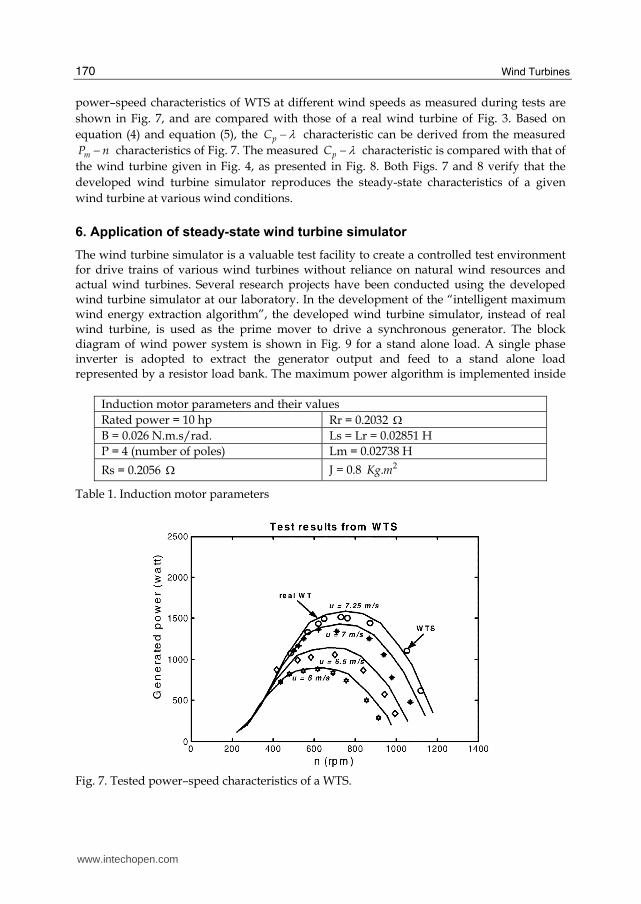
power–speed characteristics of WTS at different wind speeds as measured during tests are
shown in Fig. 7, and are compared with those of a real wind turbine of Fig. 3. Based on
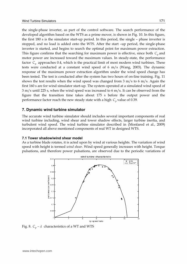
equation (4) and equation (5), the pC λ− characteristic can be derived from the measured
mP n− characteristics of Fig. 7. The measured pC λ− characteristic is compared with that of
the wind turbine given in Fig. 4, as presented in Fig. 8. Both Figs. 7 and 8 verify that the
developed wind turbine simulator reproduces the steady-state characteristics of a given
wind turbine at various wind conditions.
6. Application of steady-state wind turbine simulator
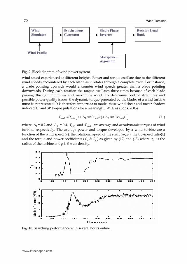
The wind turbine simulator is a valuable test facility to create a controlled test environment for drive trains of various wind turbines without reliance on natural wind resources and actual wind turbines. Several research projects have been conducted using the developed wind turbine simulator at our laboratory. In the development of the “intelligent maximum wind energy extraction algorithm”, the developed wind turbine simulator, instead of real wind turbine, is used as the prime mover to drive a synchronous generator. The block diagram of wind power system is shown in Fig. 9 for a stand alone load. A single phase inverter is adopted to extract the generator output and feed to a stand alone load represented by a resistor load bank. The maximum power algorithm is implemented inside
Induction motor parameters and their values
Rated power = 10 hp Rr = 0.2032 Ω
B = 0.026 N.m.s/rad. Ls = Lr = 0.02851 H
P = 4 (number of poles) Lm = 0.02738 H
Rs = 0.2056 Ω J = 0.8 2.Kg m
Table 1. Induction motor parameters
Fig. 7. Tested power–speed characteristics of a WTS.
www.intechopen.com
Wind Turbine Simulators
171
the single-phase inverter, as part of the control software. The search performance of the
developed algorithm based on the WTS as a prime mover, is shown in Fig. 10. In this figure,
the first 180 s is the simulator start-up period. In this period, the single – phase inverter is
stopped, and no load is added onto the WTS. After the start –up period, the single-phase
inverter is started, and begins to search the optimal point for maximum power extraction.
This figure confirms that the searching for maximum power is effective, since both pC and
motor power are increased toward the maximum values. In steady-state, the performance
factor pC approaches 0.4, which is the practical limit of most modern wind turbines. These
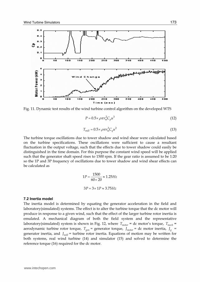
tests were conducted at a constant wind speed of 6 m/s (Wang, 2003). The dynamic
response of the maximum power extraction algorithm under the wind speed change has
been tested. The test is conducted after the system has two hours of on-line training. Fig. 11
shows the test results when the wind speed was changed from 3 m/s to 6 m/s. Again the
first 160 s are for wind simulator start-up. The system operated at a simulated wind speed of
3 m/s until 225 s, when the wind speed was increased to 6 m/s. It can be observed from the
figure that the transition time takes about 175 s before the output power and the
performance factor reach the new steady state with a high pC value of 0.39.
7. Dynamic wind turbine simulator
The accurate wind turbine simulator should includes several important components of real wind turbine including, wind shear and tower shadow effects, larger turbine inertia, and turbulent wind speed. The wind turbine simulator described in (Monfared et al., 2009) incorporated all above mentioned components of real WT in designed WTS.
7.1 Tower shadow/wind shear model
As a turbine blade rotates, it is acted upon by wind at various heights. The variation of wind speed with height is termed wind shear. Wind speed generally increases with height. Torque pulsations, and therefore power pulsations, are observed due to the periodic variations of
Fig. 8. pC λ− characteristics of a WT and WTS
www.intechopen.com
Wind Turbines
172
Fig. 9. Block diagram of wind power system
wind speed experienced at different heights. Power and torque oscillate due to the different wind speeds encountered by each blade as it rotates through a complete cycle. For instance, a blade pointing upwards would encounter wind speeds greater than a blade pointing downwards. During each rotation the torque oscillates three times because of each blade passing through minimum and maximum wind. To determine control structures and possible power quality issues, the dynamic torque generated by the blades of a wind turbine must be represented. It is therefore important to model these wind shear and tower shadow induced 1P and 3P torque pulsations for a meaningful WTE as (Lops, 2005).
( ) ( )1 31 sin sin 3mech mill mill millT T A t A tω ω⎡ ⎤= + +⎣ ⎦ (11)
where 1A = 0.2 and 3A = 0.4, millT and mechT are average and aerodynamic torques of wind
turbine, respectively. The average power and torque developed by a wind turbine are a
function of the wind speed (u), the rotational speed of the shaft ( millω ), the tip-speed ratio(λ)
and the torque and power coefficients ( qC & pC ) as given by (12) and (13) where mr is the
radius of the turbine and ρ is the air density.
Fig. 10. Searching performance with several hours online.
Wind
Simulator
Synchronous
Generator
Single Phase
Inverter
Resistor Load
Bank
Max-power
Algorithm
Wind Profile
www.intechopen.com
Wind Turbine Simulators
173
Fig. 11. Dynamic test results of the wind turbine control algorithm on the developed WTS
2 30.5 m pP r C uρπ= × (12)
3 20.5mill m qT r C uρπ= × (13)
The turbine torque oscillations due to tower shadow and wind shear were calculated based on the turbine specifications. These oscillations were sufficient to cause a resultant fluctuation in the output voltage, such that the effects due to tower shadow could easily be distinguished in the time domain. For this purpose the constant wind speed will be applied such that the generator shaft speed rises to 1500 rpm. If the gear ratio is assumed to be 1:20 so the 1P and 3P frequency of oscillations due to tower shadow and wind shear effects can be calculated as
15001 1.25
60 20P Hz= ≈×
3 3 1 3.75P P Hz= × ≈
7.2 Inertia model
The inertia model is determined by equating the generator acceleration in the field and
laboratory(simulated) systems. The effect is to alter the turbine torque that the dc motor will
produce in response to a given wind, such that the effect of the larger turbine rotor inertia is
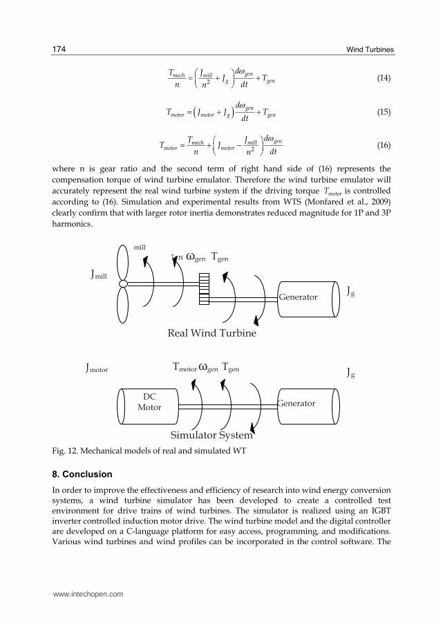
emulated. A mechanical diagram of both the field system and the representative
laboratory(simulated) system is shown in Fig. 12, where motorT = dc motor’s torque, mechT =
aerodynamic turbine rotor torque, genT = generator torque, motorJ = dc motor inertia, gJ =
generator inertia, and millJ = turbine rotor inertia. Equations of motion may be written for
both systems, real wind turbine (14) and simulator (15) and solved to determine the
reference torque (16) required for the dc motor.
www.intechopen.com
Wind Turbines
174
2
genmech millg gen
dT JJ T
n dtn
ω⎛ ⎞= + +⎜ ⎟⎝ ⎠ (14)
( ) genmotor motor g gen
dT J J T
dt
ω= + + (15)
2
genmech millmotor motor
dT JT J
n dtn
ω⎛ ⎞= + −⎜ ⎟⎝ ⎠ (16)
where n is gear ratio and the second term of right hand side of (16) represents the
compensation torque of wind turbine emulator. Therefore the wind turbine emulator will
accurately represent the real wind turbine system if the driving torque motorT is controlled
according to (16). Simulation and experimental results from WTS (Monfared et al., 2009)
clearly confirm that with larger rotor inertia demonstrates reduced magnitude for 1P and 3P
harmonics.
Real Wind Turbine
Simulator System
Generator
mill 1: n ωgen Tgen
Generator DC
Motor
Tmotor ωgen Tgen
Jg
Jg
Jmill
Jmotor
Fig. 12. Mechanical models of real and simulated WT
8. Conclusion
In order to improve the effectiveness and efficiency of research into wind energy conversion systems, a wind turbine simulator has been developed to create a controlled test environment for drive trains of wind turbines. The simulator is realized using an IGBT inverter controlled induction motor drive. The wind turbine model and the digital controller are developed on a C-language platform for easy access, programming, and modifications. Various wind turbines and wind profiles can be incorporated in the control software. The
www.intechopen.com
Wind Turbine Simulators
175
experimental results show that the steady-state characteristics of the WTS are similar to those of the given wind turbine. Various tests conducted on the developed WTS for real wind turbine and the resultant responses of a variety of WTS parameters have confirmed the performance of the wind turbine simulator under the designed digital controllers. The accurate wind turbine simulator should includes several important components of real wind turbine including, wind shear and tower shadow effects, larger turbine inertia, variable wind speed, and steady state characteristics.
9. References
Abelo. B.; Hofmann. W.; Gluck, M. (2004). Emulation of the Static and Dynamic Behavior of a Wind Turbine with a DC Machine, in Proc. of 35th IEEE Power Electronics Specialists Conference (PESC-05), pp. 107 – 2112, Jun. 2004,.
Battaiotto, P. E.; Mantz, R. J.; Puleston, P. f. (1996). A wind turbine emulator based on a dual DSP processor system, Control Engineering Practice, Vol. 4, No. 9, 1996, pp. 1261–1266.
Bose, B. K.(1986) Power Electronics and AC Drives. Englewood Cliffs, NJ:Prentice-Hall, 1986. Guangchen, L.; Shengti, W.; Jike, Z. (2010). Design and Realization of DC Motor and Drives
Simulator for Small Wind Turbine, Proceedings of Power and Energy Engineering Conference (APPEEC) pp. 1-4, China, March 2010, Chengdu
Jian. L.; Xu. W. C.(1987). The simulation system of wind turbine performance using a microcomputer controlled SCR-DC motor, in Proc. Beijing Int. Conf. Electrical Machines, pp. 865-868. Beijing, China, 1987
Lopes, L. A. C.; Lhuilier, J.; Mukherjee, A.; Khokar, M. F. (2005). A Wind Turbine Emulator that Represents the Dynamics of the Wind Turbine Rotor and Drive Train, 36th IEEE Conf. Power Electronics Specialists, pp. 2092-2097, 12 Jun 2005
Madadi kojabadi, H.; Chang, L. (2005). A Novel Steady State Wind Turbine Simulator Using an Inverter Controlled Induction Motor, Wind Engineering, Vol. 28, No. 4, 2004, pp. 433-443
Madadi Kojabadi, H,. Chang, L., Boutot, T. (2004), Development of a Novel Wind Turbine Simulator for Wind Energy Conversion Systems Using an Inverter- Controlled Induction Motor, IEEE Trans. On Energy Conversion, Vol. 19, No. 4., 2004, pp. 547-552.
Monfared, M. Madadi kojabadi, H., Rastegar, H., (2009), Static and dynamic wind turbine simulator using a converter controlled dc motor, Renewable Energy, Elsevier, Vol. 34, 2009, pp. 845-848
Nichita, C.; Diop, A. D.; Elhache, G.; Dakyo, B.; Protin, L. (1998). Control structures analysis for a real wind system simulator, Wind Engineering, Vol. 22, No. 6, 1998, pp. 275-286,
Nunes, A. A.; Seixa, C. P. F.;. Cortizo, P. C.;. Silva, S. R.(1993). Wind turbine simulator using a dc machine and a power reversible converter, in Procceedings of the International Conf. On Electrical Machines, ICEMA, pp. 536-540, Adelaide, 1993
Rashid, M. H. (1993). Power Electronics: Circuits Devices, and Applications Englewood Cliffs, NJ: Prentice-Hall, 1993.
Wang, Q. (2003). Maximum wind energy extraction strategies using power electronic converters, Ph.D. Thesis, University of New Brunswick, Fredericton, Canada, 2003.
www.intechopen.com

Wind Turbines
176
Weihao, Hu, Yue, W., Xianwen, S, Zhaoan, W, (2009), Development of wind turbine simulator for wind energy conversion systems based on permanent magnet synchronous motor, Electrical Machines and systems, pp. 2322-2326, Feb. 2009 Wuhan, China
Yun, D.; Han, B.; Choi, N. ( 2009). Hardware simulator for PMSG wind power system with matrix converter, International Conference on Telecommunications Energy, pp. 1-6, Incheon, Oct. 2009, China.
www.intechopen.com

Wind TurbinesEdited by Dr. Ibrahim Al-Bahadly
ISBN 978-953-307-221-0Hard cover, 652 pagesPublisher InTechPublished online 04, April, 2011Published in print edition April, 2011
InTech EuropeUniversity Campus STeP Ri Slavka Krautzeka 83/A 51000 Rijeka, Croatia Phone: +385 (51) 770 447 Fax: +385 (51) 686 166www.intechopen.com
InTech ChinaUnit 405, Office Block, Hotel Equatorial Shanghai No.65, Yan An Road (West), Shanghai, 200040, China
Phone: +86-21-62489820 Fax: +86-21-62489821
The area of wind energy is a rapidly evolving field and an intensive research and development has taken placein the last few years. Therefore, this book aims to provide an up-to-date comprehensive overview of thecurrent status in the field to the research community. The research works presented in this book are dividedinto three main groups. The first group deals with the different types and design of the wind mills aiming forefficient, reliable and cost effective solutions. The second group deals with works tackling the use of differenttypes of generators for wind energy. The third group is focusing on improvement in the area of control. Eachchapter of the book offers detailed information on the related area of its research with the main objectives ofthe works carried out as well as providing a comprehensive list of references which should provide a richplatform of research to the field.
How to referenceIn order to correctly reference this scholarly work, feel free to copy and paste the following:
Hossein Madadi Kojabadi and Liuchen Chang (2011). Wind Turbine Simulators, Wind Turbines, Dr. Ibrahim Al-Bahadly (Ed.), ISBN: 978-953-307-221-0, InTech, Available from: http://www.intechopen.com/books/wind-turbines/wind-turbine-simulators