Embed Size (px)
Citation preview
Wind Generator Stabilization with Doubly-Fed Asynchronous Machine
Li Wu*, Junji Tamura,Zhixin Wang*
Electrical Engineering Department,Shanghai Jiao Tong University 1954 Huashan Road,200030,P.R.China
Abstract: - This paper mainly deals with the investigations concerning the transient stability enhancement of wind power systems with DASM(Doubly–fed ASynchronous Machine). Generation of electricity using wind power has received considerable attention worldwide in recent years. However, many concerns have been focused on three principal problems of the wind generator system. (problem 1): Reactive power compensation for the operation of the general wind generator (induction machine) in steady state; (Problem 2): Reactive power compensation for the operation of the general wind generator (induction machine) when a large electrical disturbance occurs in the network; (Problem 3): Active power compensation for the operation of the general wind generator when wind power fluctuates. On the other hand, Doubly-fed Asynchronous Machine is a powerful system stabilization methodology with a myriad of applications in energy storage field, when properly controlled, can be used to solve the problem at a time. In this paper, simulation studies by PSCAD (Power System Computer Aided Design)/EMTDC were performed to verify the effectiveness of the DASM on the stabilization of wind generator system when a 3LG (Three-phase-to-ground) fault occurs and when wind generators suffer severe wind speed variations. Key-Words: - DASM(Doubly–fed ASynchronous Machine), wind Generator, Wind turbine Pitch Control, PSCAD/EMTDC. 1 Introduction Generation of electricity using wind power has received considerable attention worldwide in recent years. It has been predicted that the annual growth of wind power between 1998 and 2040 would be between 20-30%[1]. However, the continuous trend of the increasing of the number of wind generators would influence the operation of existing utilities networks. Up to now many concerns[2]-[5] have been focused on three principal problems of the wind generator system: (problem 1): Reactive power compensation is required for the operation of the general wind generator (induction machine) in steady state, otherwise the power quality of the system will be decreased; (problem 2): When a large electrical disturbance occurs in the network , the terminal voltage of the wind farm will decrease while the rotor speed of the machine will increase tremendously, which will lead to the collapse down of the system; (problem 3):When wind power fluctuates tremendously due to wind speed variations such as wind gust, the power delivered to the network system will suffer power surge if there is no adequate amount of active power compensation.
Although various ways, such as capacitor banks have been supposed to compensate the reactive power for the wind generator in steady state, because
of its fixed capacity, the reactive power supplied to the wind generator will be superfluous sometimes while insufficient sometimes, depending on the output of the generator. Controlled static VAR compensation [6] [7] can offer the variable reactive power compensation both for steady state and transient state. When large electrical disturbances, such as 3LG (three-line-to-ground) fault, occurs in the network, terminal voltage will decrease, thus rotor speed of the wind generator will be accelerated, and consequently much more reactive power will be consumed from the network system, which leads to the drop of the wind farm voltage. As SVC can respond to this with adequate amount of reactive power compensation, wind farm voltage, and also wind generator rotor speed can recover to the initial state. In addition, since wind farm suffer severe wind gust frequently, when wind speed fluctuates, active power supplying to the network will also fluctuate accordingly. However, at this time active power compensation from SVC is impossible. The combination of SVC and battery storage system [8] [9] seem to be a solution to all the three problems, in which active and reactive power compensation can be supplied at a time. However, in this case, full capacity inverter is required, which makes the system costly, and harmonic is inevitable. Moreover, in the
Proc. of the 5th WSEAS/IASME Int. Conf. on Electric Power Systems, High Voltages, Electric Machines, Tenerife, Spain, December 16-18, 2005 (pp486-495)

battery storage system, the output of the active power cwheel generator by using DASM for the stabilization of the power system [12]. However, up to now, few discussions have been done on the stabilization of wind generator by flywheel generator using DASM.
Therefore, it is supposed that DASM, when properly controlled, can be used to provide locally the leading reactive power compensation for the wind generator in steady state; be used to stabilize the wind power system under large electrical disturbances in the network, with adequate amount of reactive power compensation; and be used to stabilize the wind power system under a severe wind gust, with adequate amount of active power compensation. In this paper, DASM, with proper control scheme, is proposed to enhance the stability of wind generator system, and various simulations are done to verify the propositions above.
Simulation studies by PSCAD (Power System Computer Aided Design)/EMTDC were performed to verify the effectiveness of the DASM on the stabilization of wind generator system when a 3LG fault occurs and when wind generators suffer severe wind gusts. In each of the section, various simulation models used in the simulation, sucan not change rapidly due to its chemical limitation. So after all, no ways have been found to solve the above three problems at a time.
DASM(Doubly-fed Asynchronous machine) seems to be a solution to these problems. It has been emerged as a system stabilizer by injecting/absorbing adequate amount of active/reactive power quickly and instantaneously to the network system. The rotor of the DASM fed by a three-phase, sinusoidal current of slip frequency, which enables to regulate the active and reactive power compensation for the system independently through secondary excitation controlling [10]. Moreover, as compared to the combination of SVC and battery storage system, the capacity of the inverter required for the system is about 0.3 times the DASM power rating, which makes it cheaper. In addition, less harmonics is found, and it is much quicker in its electrical action. So DASM might be a good solution to the 3 problems facing the wind generator system.
It is well known that hydro generator by using DASM has been put into practical use successfully [11]. On the other hand, there are also some reports concerning the application of flyh as model system configuration, DASM and its rotor control scheme, wind turbine model and pitch control system, are explained in detail, and reasons of being selected are also given. In section II, simulation studies on the effectiveness of the DASM on transient stability
problems have been done on single wind generator system, comparison studies between the wind turbine pitch control and proposed method on single wind generator system when 3LG fault occurs have also been done. Section III provides simulation results and analysis on the effectiveness of the DASM on transient stability problems of multiple wind generator system. In section IV, a typical kind of real wind speed pattern is used to verify the effectiveness of DASM on smoothing power surge and terminal voltage of the wind farm during wind gust. Section VI draws various conclusions from the simulations above. 2 Single Wind Generator Stabilization with Doubly-Fed Asynchronous Machine during a Fault
It is well known that the general way to deal with wind generators when a fault such as a 3LG (three-line-to-ground) fault occurs in the network system is to disconnect them from the grid and then apply brake to stop them. Although there are also reports investigating the effect of the pitch control system on the transient stability recently[13], restrictions of the mechanical system limit the change rate of the pitch angle, and in turn the stabilization ability of the pitch control system. In this section a new way of compensating the amount of required reactive power from DASM to recover the voltage when a 3LG fault occurs is proposed, various simulation model are explained, simulation results are analyzed and discussed to verify the proposed propositions.
2.1 Model system configuration The system used as a basis for this investigation is
shown in Fig. 1, in which SG denotes a synchronous generator and a DASM is connected to the high-voltage side of a wind generator (induction generator, IG) through a Δ/Y transformer. Table 1 shows various parameters of each generator. There is a local transmission line with one circuit between the main transmission line and a transformer at the wind power station.
Though a wind power station is composed of many generators practically, it is considered to be composed of a single generator with total power capacity in the first few parts of the paper. A condenser C, is connected to the terminal of the wind generator to compensate the reactive power demand for the induction generator in steady state. The value of C has been chosen so that the power factor of the
Proc. of the 5th WSEAS/IASME Int. Conf. on Electric Power Systems, High Voltages, Electric Machines, Tenerife, Spain, December 16-18, 2005 (pp486-495)

wind power station becomes unity when the terminal voltage and output power are 1.0[pu].
AVR and governor control systems are considered in the synchronous generator model, and they are shown in detail in Fig.2. 2.2 DASM and its Control Scheme
The DASM used is based on a wound rotor structure, whose rotor is supplied with an alternating current of slip frequency. Therefore the resulting magnetic flux due to the impressed rotor currents, rotates with slip frequency referred to the rotor and with the network frequency referred to the stator; whereby it generates the corresponding counter magnetic flux within the stator. So the amplitude and phase position of the stator current and thereby the active and reactive power consumption of the machine is determined by control of the rotor current. Although various ways[14],[15],[16] has been proposed to control the rotor current, the simplest way of PI controlling is used in the paper, to verify the effectiveness of the DASM to the stabilization of the wind power system. Moreover, in the paper the rotating reference frame (dq frame) to analyze the DASM is fixed on the space axis of stator voltage.
In the control scheme illustrated in Fig.3[10], when PWG (active power from wind farm into the network system) and VWG(wind farm terminal voltage) are detected, the P/Q compensation required from DASM is thus determined. To regulate the error between the desired and detected values of P/Q, a two-step PI controller is used, the first step of which is APR/AQR, and the second is ACR. These controllers are shown in Fig.4. Therefore the required field voltage is specified and applied to the rotor side of the DASM. In Fig.4, PWG and P are the active power output and its reference value of wind farm; P
refWG
DASM and P are the active power detection and
its reference value of DASM;Q
refDASM
DASM and Q are the reactive power detection and its reference value of DASM respectively. V
refDASM
WG and V are detection and its reference value of the wind farm terminal voltage respectively, and V
refWG
WG is the RMS value of the detected three phase instantaneous values Va, Vb, Vc, and given by
VWG =3
222VcVbVa ++ …………………(1)
In the paper, we simulate the secondary-exciting source with an ideal DC source for the sake of simplicity, and only the fundamental component of inverter output is considered[10].
DASM
CB CB
IG
Infin ite bus
VWG
Transmission line
3LG
j0.1
50Hz, 100MVA BASE
PWG
j0.1 P=1.0[pu],V=1.03[pu]
SG
j0.2
0.04+j0.2 V=1.0[pu]
Secondaryexcita t ion
cont rol
j0.2
0.05
+j0.
3
C
Fig.1 Power system model
Vs
Vs0 Efd0
Efd + +
+
-
s5.0125+
(a) AVR Model
ωm
ωm0=1pu
PM0
PM
+ +
+ -
s0.2120+
(b) Governor Model
Fig.2 Control system models of synchronous generator
Wind farm
active power deviation
ACR APR
ACR
Desired
va lue
AQR
→dq
a bc ← inver ter
DASM
ωr
θr
θ e
Network
system
Kv
Active
power
detect ion
React ive
Power
detect ion
Phase
detect ion
Wind farm
voltage
deviation
θ s +
+
+
+
+ -
-
-
-
-
∫
Rotor currentdetection
KP Fig.3 DASM circuit configuration
Proc. of the 5th WSEAS/IASME Int. Conf. on Electric Power Systems, High Voltages, Electric Machines, Tenerife, Spain, December 16-18, 2005 (pp486-495)

2.3 Derivation of Wind Turbine Model
In general, the developed torque of a wind turbine, τW, can be expressed as follows [17]:
2wTTw UCK=τ ……………………………(2)
Where KT is a constant determined by the density of the air and the radius of windmill, CT denotes the windmill torque coefficient, and UW denotes the wind speed. It is assumed in this section that the wind speed is constant, because the variation of the wind speed during the short time span of the analyses of transient stability can be considered negligible. Therefore the developed torque, τW, can be expressed as a function of only the windmill torque coefficient as follows:
TTw CK '=τ …………………………………(3) The windmill torque coefficient, CT, can be
expressed approximately by using the blade pitch angle of windmill, βW (deg), and the angular speed rate of windmill, λW, as follows[16]:
CT = (C1βW + C2) λW + (C3βW + C4) ………(4) Where C1,2,3,4 are constants. The above expression
is a straight line approximation of real windmill torque characteristics. Because it is assumed that the wind speed is constant, the angular speed rate of windmill, λW, becomes a function of only windmill speed, ωm, which is equal to the wind generator speed in pu (per unit) system. Therefore, substituting eq.(4) into eq.(3) yields new expression of the pu developed torque as follows, in which ωm denotes pu generator speed, and βdenotes pu blade pitch angle of windmill.
Fig.4 Control signal blocks for DASM
τw[pu]=(C1´β+C2´)ωm[pu]+(C3´β+C4´) ………(5) Referring to the windmill torque coefficient of
eq.(4) presented in [17], the authors of this paper has determined C1´,C2´,C3´ and C4´ in eq.(5) as follows:
TABLE 1 . NOMINAL VALUES AND PARAMETERS OF EACH GENERATOR
C1´=-0.632 C2´=-0.101 C3´=-0.373 C4´=1.115 …………………(6)
Fig.5 shows the torque characteristics expressed by eqs.(5) and (6). β has been normalized so that β is zero when the wind generator is operating at steady state condition and is one when the developed torque of wind turbine is zero at the same speed, as shown in the figure. The base torque for τW (pu) is the rated torque of the wind generator. 2.4 Pitch Control System Model
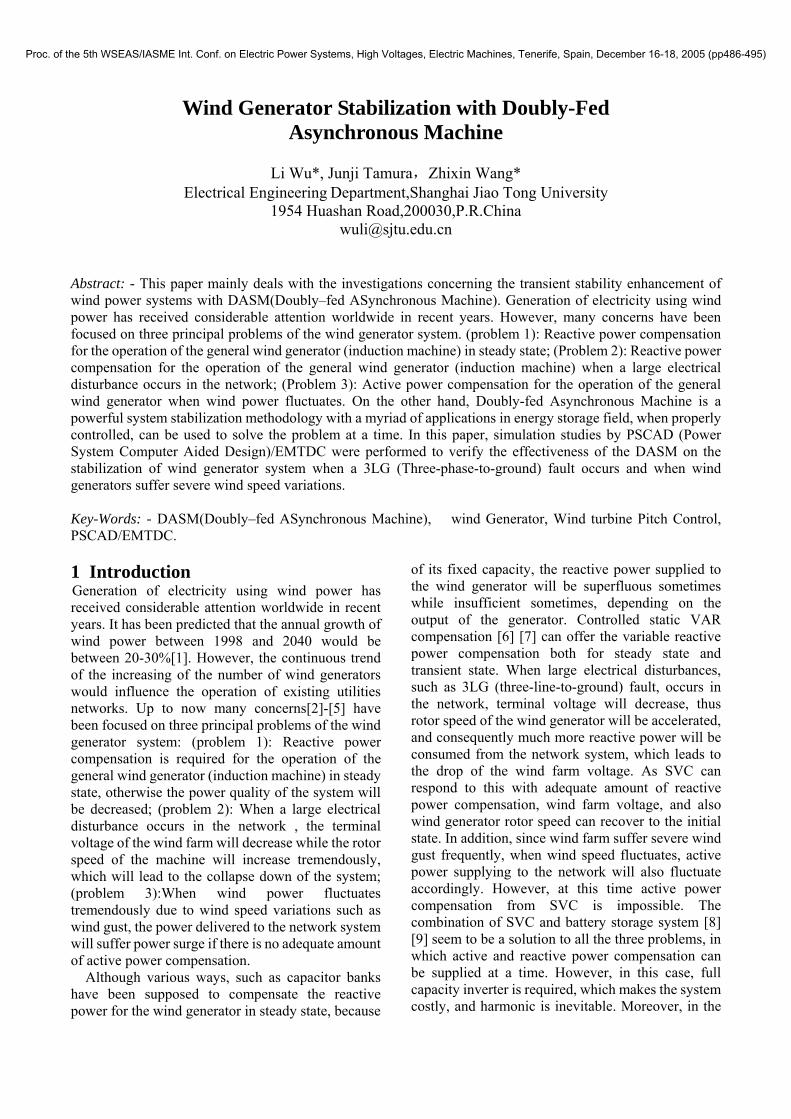
Fig.6 shows the pitch control system of wind turbine considered in this paper. In general, the main purpose of the pitch control system is to maintain the constant output of wind generator. However, this control system may decrease the transient stability of the wind generator which is accelerating due to short circuit faults in the power system. On the other hand,
SG Wind generator(IG) DASMRated output
(MVA) 100 Rated output (MVA) 50 50
Rated voltage(KV) 11 Rated
voltage(KV) 0.69 11
ra(pu) 0.003 r1(pu) 0.01 0.0045xa(pu) 0.13 x1(pu) 0.1 0.142 Xd(pu) 1.2 Xmu(pu) 3.5 2.75 Xq(pu) 0.7 r2(pu) 0.01 0.0045
Xd′(pu) 0.3 x2(pu) 0.08 0.142 Xd″(pu) 0.22 H(sec) 1.5 19.5 Xq″(pu) 0.25
Tdo′(sec) 5.0 Td″(sec) 0.04 Tq″(sec) 0.05
H(sec) 2.5
0.9 1.0 1.1 1.2 1.30.0
0.2
0.4
0.6
0.8
1.0(1.00101, 1.0127)
Initial operating point
β=1.0β=0.8
β=0.6
β=0.4
β=0.2
β=0
τW[pu]
ωm[pu]
Fig.5 Wind turbine torque characteristic
Proc. of the 5th WSEAS/IASME Int. Conf. on Electric Power Systems, High Voltages, Electric Machines, Tenerife, Spain, December 16-18, 2005 (pp486-495)
another pitch control system to prevent the windmill from excess speed increase is mostly equipped with the wind turbine from a point of view of protecting the windmill. Though the purpose of the latter control system is not to enhance the transient stability of the wind generator, it can enhance the transient stability. There are reports investigating the effect of the pitch control system on the transient stability enhancement[13].
In this paper, pitch control system shown in Fig.6 is considered and its effect on the transient stability is analyzed. Control blocks in Fig.6 means that if about 10% increase of generator speed appears, the pitch controller reduces the wind turbine torque to zero with time constant of TW sec.
As in reality, because of the mechanical restrictions of the control system of the pitch angle, the change rate of it has been limited to vary from 3[deg]/[sec] to 10[deg]/[sec], depending on the size of the wind turbine. So in the paper the time constant TW of the control system has been chosen as TW=3[sec] to simulate the fastest response in reality. In addition, the minimum output torque of the turbine has been limited to 0 to ensure it works as a generator.
2.5 Simulation Cases and Some Initial Conditions
To investigate the validity of the proposed method, a 3LG fault is applied in the following three kinds of circumstances, and simulation results are studied and compared:
(Case 1): Capacitor banks are connected at the terminal of the wind generator to offer the required reactive power in steady state.
(Case 2): Capacitor banks are connected at the terminal of the wind generator and pitch control systems described in Section III.D are equipped with the wind turbine.
(Case 3): Without the capacitor banks and the pitch control systems, DASM is placed nearby to provide the required reactive power compensation in steady state. The mechanical input to the DASM is 0 [pu] and the output from DASM has been limited to 0.5[pu](rated value).
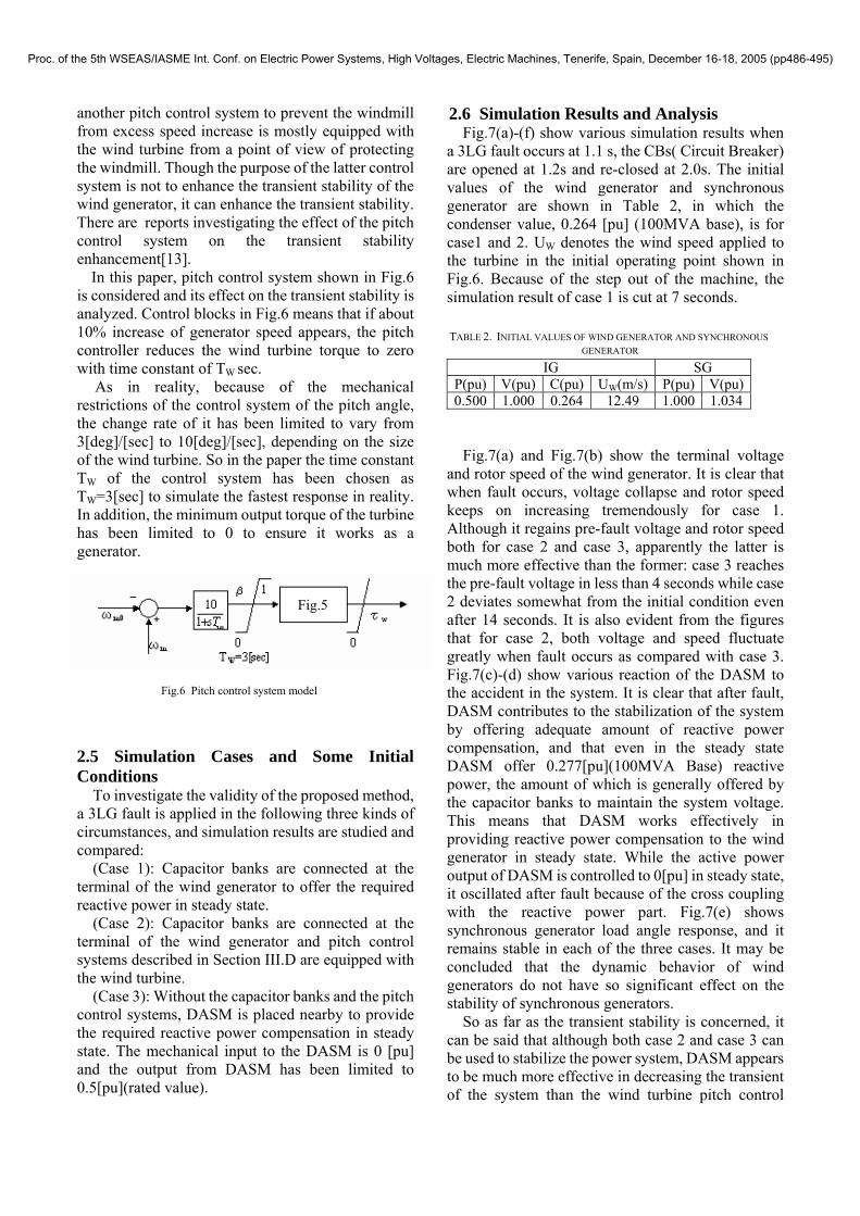
2.6 Simulation Results and Analysis Fig.7(a)-(f) show various simulation results when
a 3LG fault occurs at 1.1 s, the CBs( Circuit Breaker) are opened at 1.2s and re-closed at 2.0s. The initial values of the wind generator and synchronous generator are shown in Table 2, in which the condenser value, 0.264 [pu] (100MVA base), is for case1 and 2. UW denotes the wind speed applied to the turbine in the initial operating point shown in Fig.6. Because of the step out of the machine, the simulation result of case 1 is cut at 7 seconds. TABLE 2. INITIAL VALUES OF WIND GENERATOR AND SYNCHRONOUS
GENERATOR
Fig.7(a) and Fig.7(b) show the terminal voltage
and rotor speed of the wind generator. It is clear that when fault occurs, voltage collapse and rotor speed keeps on increasing tremendously for case 1. Although it regains pre-fault voltage and rotor speed both for case 2 and case 3, apparently the latter is much more effective than the former: case 3 reaches the pre-fault voltage in less than 4 seconds while case 2 deviates somewhat from the initial condition even after 14 seconds. It is also evident from the figures that for case 2, both voltage and speed fluctuate greatly when fault occurs as compared with case 3. Fig.7(c)-(d) show various reaction of the DASM to the accident in the system. It is clear that after fault, DASM contributes to the stabilization of the system by offering adequate amount of reactive power compensation, and that even in the steady state DASM offer 0.277[pu](100MVA Base) reactive power, the amount of which is generally offered by the capacitor banks to maintain the system voltage. This means that DASM works effectively in providing reactive power compensation to the wind generator in steady state. While the active power output of DASM is controlled to 0[pu] in steady state, it oscillated after fault because of the cross coupling with the reactive power part. Fig.7(e) shows synchronous generator load angle response, and it remains stable in each of the three cases. It may be concluded that the dynamic behavior of wind generators do not have so significant effect on the stability of synchronous generators.
So as far as the transient stability is concerned, it can be said that although both case 2 and case 3 can be used to stabilize the power system, DASM appears to be much more effective in decreasing the transient of the system than the wind turbine pitch control
IG SG P(pu) V(pu) C(pu) UW(m/s) P(pu) V(pu)0.500 1.000 0.264 12.49 1.000 1.034
Fig.5
Fig.6 Pitch control system model
Proc. of the 5th WSEAS/IASME Int. Conf. on Electric Power Systems, High Voltages, Electric Machines, Tenerife, Spain, December 16-18, 2005 (pp486-495)

system. The results also show that instead of conventional capacitor bank, the DASM works effectively in providing locally the leading reactive power compensation to the wind generator in steady state. 2.7 Discussions:
The followings are some discussions on the simulation results and conclusions:
1) It is concluded above that both pitch control and DASM can be used to the stabilization of the wind generator system. But concerning the ability of stabilization, DASM is much more effective than the pitch control. Although it seems that by decreasing the value of Tw, the ability of pitch control can be improved, it is impossible. As Tw is the time constant of pitch controller for wind turbine, it corresponds to the speed at which pitch angle changes. The pitch angle of the blades can not be changed so fast because the twisting of the pitch will give big stress to the blade.
2) Just as described above, to stabilize the wind generator system in transient state, adequate amount of reactive power compensation is needed. Although it seems that capacitor banks can function as the stabilizer at this time, it is also not effective. Generally, the value of capacitor banks is determined to satisfy the steady state reactive power requirement. But when 3LG fault occurs, capacitor banks can not satisfy the huge reactive power requirement due to terminal voltage drops. In the meantime, if the value of capacitor bank is set in a way to satisfy the huge reactive power requirement when 3LG fault occurs, the reactive power supplied will be superfluous for steady state, and the terminal voltage will go beyond the voltage limitation. On the other hand, in contrast to the fixed capacity of condenser bank, the reactive power output of DASM can be widely changed to compensate the voltage variation, both for steady state and transient state.
0 2 4 6 8 1 0 1 2 1 4 1 6
1 .0
1 .2
1 .4
1 .6
1 .8
2 .0
0 2 4 6 8 1 0 1 2 1 4 1 6
0 .0
0 .2
0 .4
0 .6
0 .8
1 .0
1 .2
T im e [s e c ]
IG Term
inal Voltage [pu
]
C a s e 1
C a s e 3
C a s e 2
C a s e 1 C a s e 2 C a s e 3
Fig.7(a) IG terminal voltage
IG Rotor Spe
ed [pu]
C a s e 1 C a s e 2 C a s e 3
T im e [s e c ]
Fig.7(b) IG rotor speed
0 2 4 6 8 1 0 1 2 1 4 1 6
- 0 .4
- 0 .2
0 .0
0 .2
0 .4
0 .6
DASM Active Power [pu]
T im e [s e c ]
Fig.7(c) DASM active power output(case 3)
0 2 4 6 8 1 0 1 2 1 4 1 6
- 0 .4
- 0 .2
0 .0
0 .2
0 .4
0 .6
DASM Reactive Power [pu]
T im e [s e c ]
Fig.7(d) DASM reactive power output(case 3)
0 2 4 6 8 1 0 1 2 1 4 1 6
0
2 0
4 0
6 0
8 0
1 0 0
1 2 0
SG Delta [deg]
T im e [s e c ]
C a s e 1 C a s e 2 C a s e 3
Fig.7(e) Synchronous generator load angle
Proc. of the 5th WSEAS/IASME Int. Conf. on Electric Power Systems, High Voltages, Electric Machines, Tenerife, Spain, December 16-18, 2005 (pp486-495)

3 Multiple Wind Generator Stabilization with Doubly-Fed Asynchronous Machine during a Fault
As explained previously, simplified lumped wind generator model was considered by now, but in most cases, wind power station is practically composed of many separated generators. In this section, to verify the stabilization ability of the proposed DASM, simulations are done on multiple wind generator system, and simulation results are analyzed. 3.1 Wind Generator Model System
In order to examine the effect of DASM on the practical multiple wind generator system, 5 wind generators (each 10 MVA power rating) with different output are used for the transient stability simulation study. The schematic model of the wind generators is shown in Fig.8 and the rest of the model are the same as those shown in Fig.1. 3.2 Simulation Cases, and Initial Conditions
Two cases below are considered in the simulation study:
(Case 4): with DASM placed nearby while without the capacitor banks at the terminals of the wind generators.
(Case 5): with capacitor banks connected at the terminals of the wind generators.
Fault conditions are the same as those described in Section III. Pitch control system of wind turbine is not considered in both cases. The initial values of each wind generator and synchronous generator are shown in Table 3.
3.3 Simulation Results and discussions Fig.9 (a)-(e) show various simulation results of the
wind generator system. From the figures, it is clear that after the fault wind generators with high output go out of step because of the high initial rotor speed. It is also clear that after the fault, for case 4 the system regains its pre-fault voltage and rotor speed due to the reactive power compensation from DASM, while the system experience voltage collapse and tremendous speed increasing for case 5. The reactive output of DASM reaches 0.29 [pu] in steady state to meet reactive power compensation requirement of the system. In addition, synchronous generator load angle shown in Fig.9(e) remains stable in each of the two cases, the dynamic behavior of the wind generators do not have so much significant effect on the stability of the synchronous generator.
It can be concluded from all the results above that DASM also work effectively on decreasing the transient of the multiple wind generator system.
Although it seems that DASM may be replaced by SVC in offering the variable reactive power when 3LG fault occurs, it is less effective because of the disability of SVC in offering active power compensation when wind power fluctuates, which will be discussed in Section V.
To the Grid
C
j1.0 IG
j1.0 IG
P(pu) 0.076 0.082 0.088 0.094 0.100V(pu) 1.011 1.009 1.006 1.003 1.000
UW(m/s) 10.95 11.35 11.74 12.12 12.49IG
C(pu) 0.053 (100 MVA Base, for Case 4) P(pu) 1.000 Q(pu) 0.222 V(pu) 1.013 TG(pu) 1.003 Ef(pu) 1.703
SG
δ(deg) 52.84
IG
IG
IG
Rated Power (IG)
10(MW)
j1.0
j1.0
j1.0
C
C
C
C
P=0.1(pu) V=1(pu)
P=0.094(pu)
P=0.088(pu)
P=0.082(pu)
P=0.076(pu)
TABLE 3. INITIAL VALUES OF THE WIND GENERATORS AND SYNCHRONOUS GENERATOR
Fig.8 Wind generator part of the model system
0 2 4 6 8 1 0
1 .0 0 0
1 .0 0 5
1 .0 1 0
1 .0 1 5
1 .0 2 0
1 .0 2 5
1 .0 3 0
1 .0 3 5
1 .0 4 0
1 .0 4 5
IG In itia l P o w e r [p u ]
IG Rotor Spe
ed [pu]
T im e [s e c ]
0 .1 0 .0 9 4 0 .0 8 8 0 .0 8 2 0 .0 7 6
Fig.9(a) IG rotor speed (Case 4)
Proc. of the 5th WSEAS/IASME Int. Conf. on Electric Power Systems, High Voltages, Electric Machines, Tenerife, Spain, December 16-18, 2005 (pp486-495)

4 Wind Power System Stabilization with Doubly-fed Asynchronous Machine during Wind Speed Variations
It is well known that the wind speed is fluctuating because of its turbulent nature and it vary on a random basis. Thereby the output of the wind generator can’t be connected to the network directly since it is continuously varying. Although the output may sometimes be maintained constant by adjusting its blade pitch angle, the generator can sometimes be unstable during highly variable wind conditions[13]. Although various ways have been tried[19],[20], this section proposed a new way using DASM to stabilize the power fluctuations from the wind farm to the network system.
0 2 4 6 8 1 0
1 .0
1 .1
1 .2
1 .3
1 .4
1 .5
IG In itia l P o w e r [p u ]
IG Rotor Speed [pu]
T im e [s e c ]
0 .1 0 .0 9 4 0 .0 8 8 0 .0 8 2 0 .0 7 6
Fig.9(b) IG rotor speed (case 5)
The two cases (case4 and case5), system model and the initial values of each wind generator and synchronous generator are totally the same as those described in section III.
0 2 4 6 8 1 0
0
2 0
4 0
6 0
8 0
1 0 0
C a s e 4 C a s e 5
SG Load Angle[pu
]
T im e [s e c ]
As the wind speed is randomly changing all the time, it is important to investigate its influence to the system when the multiple generators are under typical wind gusts. Among various wind patterns, it is considered that when 4 of the 5 wind generators are under the same type of wind gust. As all the generators will be accelerated at the same time in this case, there may be a high possibility of leading to the total collapse of the system if without the adequate compensation from DASM.
Fig.9(c) Wind farm terminal voltage
Based on the expectations above, representative wind speed pattern is chosen for the simulation, and superiority of DASM over capacitor banks when wind speed changes are tested. Wind speed variations shown in Fig.10 has been applied to 4 of the 5 wind generators for both cases, case3 and case4.
0 2 4 6 8 1 0
- 0 .2
0 .0
0 .2
0 .4
0 .6
0 .8
DASM Reactive Power[pu]
T im e [s e c ]
Fig.9(d) DASM reactive power(case 4)
Simulation results are shown in Fig.11 (a) to (d). It is clear that, for case 4, wind generators go out of step, and active power from wind farm(shown in Fig11(a)) and wind farm terminal voltage(shown in Fig 11(b)) collapse totally.
On the other hand, for case 5, since DASM supply adequate amount of active and reactive power compensations(shown in Fig. 11 (c) and (d)) to the system, both the power output and terminal voltage of the wind farm (shown in Fig. 11(a) and (b)) can be maintained almost constant.
0 2 4 6 8 1 0
0 .0
0 .2
0 .4
0 .6
0 .8
1 .0
1 .2
C a s e 4 C a s e 5
Wind Farm Term
inal Voltage[pu]
T im e [s e c ]
Fig.9(e) SG load angle Therefore it can be said that, even in the severe
wind pattern shown in Fig.10, DASM works much effectively in stabilizing the system though the wind generators go out of step if there is not DASM.
Proc. of the 5th WSEAS/IASME Int. Conf. on Electric Power Systems, High Voltages, Electric Machines, Tenerife, Spain, December 16-18, 2005 (pp486-495)

1 6
1 4
1 5
1 3
1 2
1 0
1 1
5 Conclusions
In this paper, the validity of the theory developed in this study, along with the effectiveness and viability of the control strategy, is confirmed by computer simulation. Simulation studies by PSCAD (Power System Computer Aided Design)/EMTDC were performed to verify the effectiveness of the DASM on the stabilization of wind generator system when a 3LG (Three-phase-to-ground) fault occurs and when wind generators suffer severe wind speed variations.
From the simulation results, several vital conclusions are drawn. These are:
1) Comparison studies between the wind turbine pitch control and proposed method on wind generator system when a 3LG fault occurs have been done. Results show that DASM proves to be much more effective in decreasing the transient of the system than the wind turbine pitch control system.
2) Instead of conventional capacitor bank, the DASM can work effectively in providing locally the leading reactive power compensation to the wind generator in steady state.
3) DASM can also smooth power surge and terminal voltage fluctuations of the wind farm during wind speed variations.
Thus, this paper concludes that the proposed Doubly-fed Asynchronous Machine (DASM) is effective on the stabilization of wind generator system when a 3LG fault occurs and when wind generators suffer severe wind speed variations.
6 Acknowledgment This study was supported by a Grant-in-Aid for
Scientific Research(C) from The Ministry of Education, Science, Sports and Culture of Japan.
0 3 6 9 1 2 1 5 1 8 2 1 2 4
8
9
IG In itia l P o w e r[p u ]
Wind Spe
ed [m
/s]
T im e [s e c ]
0 .1 0 .0 9 4 0 .0 8 8 0 .0 8 2
Fig.10 Wind speed variations
0 2 4 6 8 10 12 14 16 18 20 22 24
0.0
0.2
0.4
0.6
0.8
Active
Power from W
ind Farm[pu]
Time[sec]
case 3 case 4
Fig.11(a) Active power from wind farm
0 2 4 6 8 10 12 14 16 18 20 22 24
0.0
0.2
0.4
0.6
0.8
1.0
1.2
Case 3
Case 4
Wind Farm Term
inal V
oltag
e[pu]
Time[sec]
Fig.11(b) Wind farm terminal voltage
0 2 4 6 8 10 12 14 16 18 20 22 24
-0.4
-0.2
0.0
0.2
0.4
DASM A
ctive
Power[pu
]
Time[sec]
0
2
4
6
8
Fig.11(c) DASM active power(case 4)
0 2 4 6 8 10 12 14 16 18 20 22 24
0.
0.
0.
0.
0.
DASM R
eac
tive
Power
[pu]
Time[sec]
Fig.11(d) DASM reactive power (case 4)
Proc. of the 5th WSEAS/IASME Int. Conf. on Electric Power Systems, High Voltages, Electric Machines, Tenerife, Spain, December 16-18, 2005 (pp486-495)

References: [1]The European wind energy association (EWEA):
“EWEA Publication ,1998, ” [online], Available: http://www.ewea.org/Force10.htm.
[2]E. N. Hinrichsen et al. :Dynamics and Stability of Wind Turbine Generators, IEEE Transactions on PAS, Vol.PAS-101, No. 8, pp. 2640-2648,August 1982.
[3]C. S. Demoulias et al. :Electrical Transients of Windturbines in a Small Power Grid, IEEE Transactions on EC, Vol. 11, No. 3, pp. 636-642, September 1996.
[4]P. M. Anderson et al. :Stability Simulation of Wind Turbine Systems, IEEE Transactions on PAS, Vol. PAS-102, No. 12, pp.3791-3796, December 1983.
[5] J.Tamura et al: Transient Stability Simulation of Power System Including Wind Generators, Trans. IEE of Japan, Vol.120-B, No.12, pp. 1636-1645, 2000 (in Japanese).
[6]E.S.Abdin et al: Control Design and Dynamic Performance Analysis of a Wind Turbine- Induction Generator Unit, IEEE Trans. on EC, Vol. 15, No. 1, pp. 91-96,March 2000.
[7] H. Ikamoto et al: Selection of the Best Siting of Static Var Compensators for Effective Damping, Trans. IEE of Japan, Vol,115-B, No.9, pp.1054- 1063,1995(in Japanese).
[8]B.S.Borowy et al: Dynamic Response of a Stand-Alone Wind Energy Conversation System with Battery Energy Storage to a Wind Gust, IEEE Trans. on EC, Vol. 12, No. 1, pp. 73-78,March 1997.
[9]N.Kuwae et al: Wind Turbine generator and Battery Hybrid System, Trans. IEE of Japan, Vol,121-B, No.6, pp.715-721,2001(in Japanese).
[10]R.Takahashi, J.Tamura, Y.Tada, J.Kurita, Derivation of Model of an Adjustable Speed Hydro Generator and Its Control System , Trans. IEE of Japan, Vol.124-B, No.2, pp.181-189, 2004 (in Japanese).
[11]C.Takanashi et al: Principal and Effect of Variable Speed Hydro Generator System, Trans. IEE of Japan, Vol.115-B, No.5, pp.447-450,1995 (in Japanese).
[12] T.Chida et al: Stabilization of a Large-capacity and Long-distance Transmission System by combination of a System Damping Resistor and an Adjustable Speed Flywheel Generator, Vol.120-B, No.8/9, pp.1030-1038,2000(in Japanese).
[13]J.Tamura et al: Transient Stability Simulation of Power System Including Wind Generator by PSCAD/EMTDC, 2001 Porto Power Tech. Conference , No.EMT-108,2001.
[14]T. Shigetoh et al: Relationship between Robust Stability and Power System Damping Enhancement by Excitation Control System of Adjustable-Speed Generator, Trans. IEE of Japan, Vol.118-B, No.1, pp.6-13,1998.(in Japanese).
[15]K.Koyanagi et al: New Analytical Method for Studies of Enhancement of Power System Dynamic Stability by Application of Adjustable- Speed Generating System, Trans. IEE of Japan, Vol.119-B, No.1, pp.74-81,1999. (in Japanese).
[16]K. NOJIRI et al: Improvement of Power System Stability by High Speed Power Control of Adjustable Speed Machine, Trans. IEE of Japan, Vol.117-B, No.2, pp.203-209,1997. (in Japanese).
[17] K.Sasaki et al: Voltage Fluctuation Simulation of Power System Due to a Wind Driven Induction Generator, Trans. IEE of Japan, Vol..110-B, No.1, p.33,1990. (in Japanese).
[18]Y.Long et al: A method of Designing Nonlinear Observers for Squirrel-cage Induction Generators in Windmill Power Systems, Trans. IEE of Japan, Vol.120-B, No.3, pp.346-353,2000.
[19]O. Wasynczuk et al: Dynamic Behavior of a Class of Wind Turbine Generators during Random Wind Fluctuations, IEEE Transactions on PAS, Vol. PAS-100, No. 6, pp. 2837-2845, 1981.
[20]T. Matsuzaka et al: Study on Stabilization of a Wind Generator Power Fluctuation, Trans. IEE of Japan, Vol.117-B, No.5, pp.625-631,1997, (in Japanese).
Proc. of the 5th WSEAS/IASME Int. Conf. on Electric Power Systems, High Voltages, Electric Machines, Tenerife, Spain, December 16-18, 2005 (pp486-495)