Embed Size (px)
Citation preview
8/3/2019 Wind Turbine Doubly
http://slidepdf.com/reader/full/wind-turbine-doubly 1/18
Wind Turbine Doubly-Fed Induction Generator (Phasor Type) -Implement phasor model of variable speed doubly-fed induction generator driven by wind
turbine
Library
Distributed Resources/Wind Generation
Description
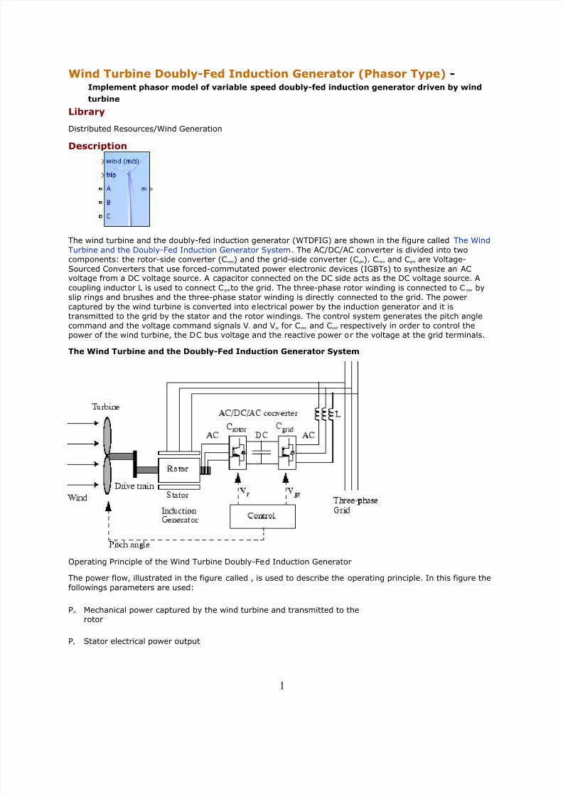
The wind turbine and the doubly-fed induction generator (WTDFIG) are shown in the figure called The Wind
Turbine and the Doubly-Fed Induction Generator System. The AC/DC/AC converter is divided into twocomponents: the rotor-side converter (Crotor ) and the grid-side converter (Cgrid). Crotor and Cgrid are Voltage-
Sourced Converters that use forced-commutated power electronic devices (IGBTs) to synthesize an AC
voltage from a DC voltage source. A capacitor connected on the DC side acts as the DC voltage source. Acoupling inductor L is used to connect Cgridto the grid. The three-phase rotor winding is connected to C rotor byslip rings and brushes and the three-phase stator winding is directly connected to the grid. The power
captured by the wind turbine is converted into electrical power by the induction generator and it istransmitted to the grid by the stator and the rotor windings. The control system generates the pitch anglecommand and the voltage command signals Vr and Vgc for Crotor and Cgrid respectively in order to control thepower of the wind turbine, the DC bus voltage and the reactive power or the voltage at the grid terminals.
The Wind Turbine and the Doubly-Fed Induction Generator System
Operating Principle of the Wind Turbine Doubly-Fed Induction Generator
The power flow, illustrated in the figure called , is used to describe the operating principle. In this figure the
followings parameters are used:
Pm Mechanical power captured by the wind turbine and transmitted to therotor
Ps Stator electrical power output
1

8/3/2019 Wind Turbine Doubly
http://slidepdf.com/reader/full/wind-turbine-doubly 2/18

8/3/2019 Wind Turbine Doubly
http://slidepdf.com/reader/full/wind-turbine-doubly 3/18
Generally the absolute value of slip is much lower than 1 and, consequently, P r is only a fraction of P s. Since
T m is positive for power generation and since ω s is positive and constant for a constant frequency grid
voltage, the sign of P r is a function of the slip sign. P r is positive for negative slip (speed greater than
synchronous speed) and it is negative for positive slip (speed lower than synchronous speed). For super-synchronous speed operation, P r is transmitted to DC bus capacitor and tends to rise the DC voltage. For
sub-synchronous speed operation, P r is taken out of DC bus capacitor and tends to decrease the DC voltage.
Cgrid is used to generate or absorb the power P gc in order to keep the DC voltage constant. In steady-state for
a lossless AC/DC/AC converter P gc is equal to P r and the speed of the wind turbine is determined by the
power P r absorbed or generated by Crotor . The power control will be explained below.
The phase-sequence of the AC voltage generated by Crotor is positive for sub-synchronous speed and negativefor super-synchronous speed. The frequency of this voltage is equal to the product of the grid frequency andthe absolute value of the slip.
Crotor and Cgrid have the capability of generating or absorbing reactive power and could be used to control thereactive power or the voltage at the grid terminals.
C_rotor Control System
The rotor-side converter is used to control the wind turbine output power and the voltage (or reactivepower) measured at the grid terminals.
Power Control
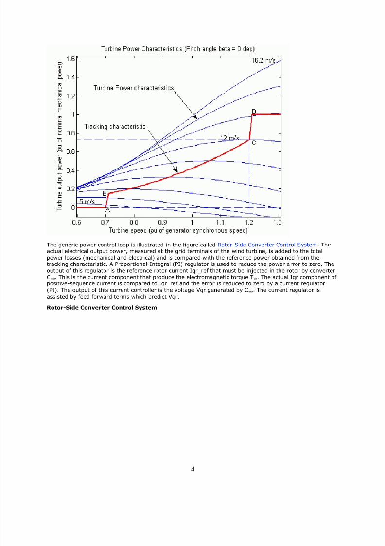
The power is controlled in order to follow a pre-defined power-speed characteristic, named tracking
characteristic. An example of such a characteristic is illustrated in the figure called Turbine Characteristicsand Tracking Characteristic, by the ABCD curve superimposed to the mechanical power characteristics of theturbine obtained at different wind speeds. The actual speed of the turbine ω r is measured and thecorresponding mechanical power of the tracking characteristic is used as the reference power for the power
control loop. The tracking characteristic is defined by four points: A, B, C and D. From zero speed to speedof point A the reference power is zero. Between point A and point B the tracking characteristic is a straight
line, the speed of point B must be greater than the speed of point A. Between point B and point C thetracking characteristic is the locus of the maximum power of the turbine (maxima of the turbine power vs
turbine speed curves). The tracking characteristic is a straight line from point C and point D. The power atpoint D is one per unit (1 pu) and the speed of the point D must be greater than the speed of point C.
Beyond point D the reference power is a constant equal to one per unit (1 pu).
Turbine Characteristics and Tracking Characteristic
3
8/3/2019 Wind Turbine Doubly
http://slidepdf.com/reader/full/wind-turbine-doubly 4/18
The generic power control loop is illustrated in the figure called Rotor-Side Converter Control System. Theactual electrical output power, measured at the grid terminals of the wind turbine, is added to the totalpower losses (mechanical and electrical) and is compared with the reference power obtained from thetracking characteristic. A Proportional-Integral (PI) regulator is used to reduce the power error to zero. The
output of this regulator is the reference rotor current Iqr_ref that must be injected in the rotor by converterCrotor . This is the current component that produce the electromagnetic torque Tem. The actual Iqr component of positive-sequence current is compared to Iqr_ref and the error is reduced to zero by a current regulator(PI). The output of this current controller is the voltage Vqr generated by Crotor . The current regulator is
assisted by feed forward terms which predict Vqr.
Rotor-Side Converter Control System
4

8/3/2019 Wind Turbine Doubly
http://slidepdf.com/reader/full/wind-turbine-doubly 5/18
Voltage Control and Reactive Power Control
The voltage or the reactive power at grid terminals is controlled by the reactive current flowing in the
converter Crotor . The generic control loop is illustrated in the figure called Rotor-Side Converter ControlSystem.
When the wind turbine is operated in voltage regulation mode, it implements the following V-I characteristic.
Wind Turbine V-I Characteristic
5

8/3/2019 Wind Turbine Doubly
http://slidepdf.com/reader/full/wind-turbine-doubly 6/18
As long as the reactive current stays within the maximum current values (-Imax, Imax) imposed by theconverter rating, the voltage is regulated at the reference voltage Vref. However, a voltage droop isnormally used (usually between 1% and 4% at maximum reactive power output), and the V-I characteristichas the slope indicated in the figure called Wind Turbine V-I Characteristic. In the voltage regulation mode,
the V-I characteristic is described by the following equation:
V = V ref + X sI
where
V Positive sequence voltage (pu)
I Reactive current (pu/Pnom) (I > 0 indicates an inductive current)
X s Slope or droop reactance (pu/Pnom)
Pnom Three-phase nominal power of the converter specified in the block
dialog box
When the wind turbine is operated in var regulation mode the reactive power at grid terminals is keptconstant by a var regulator.
The output of the voltage regulator or the var regulator is the reference d-axis current Idr_ref that must beinjected in the rotor by converter C rotor . The same current regulator as for the power control is used toregulate the actual Idr component of positive-sequence current to its reference value. The output of thisregulator is the d-axis voltage Vdr generated by Crotor . The current regulator is assisted by feed forward terms
which predict Vdr.
Vdr and Vqr are respectively the d-axis and q-axis of the voltage Vr.
Note:
for Crotor control system and measurements the d-axis of the d-q rotating reference frame is locked on
the generator mutual flux by a PLL which is assumed to be ideal in this phasor model.
the magnitude of the reference rotor current Ir_ref is equal to . The maximum
value of this current is limited to 1 pu. When Idr_ref and Iqr_ref are such that the magnitude is higherthan 1 pu the Iqr_ref component is reduced in order to bring back the magnitude to 1 pu.
C_grid Control System
The converter Cgrid is used to regulate the voltage of the DC bus capacitor. In addition, this model allows usingCgridconverter to generate or absorb reactive power.
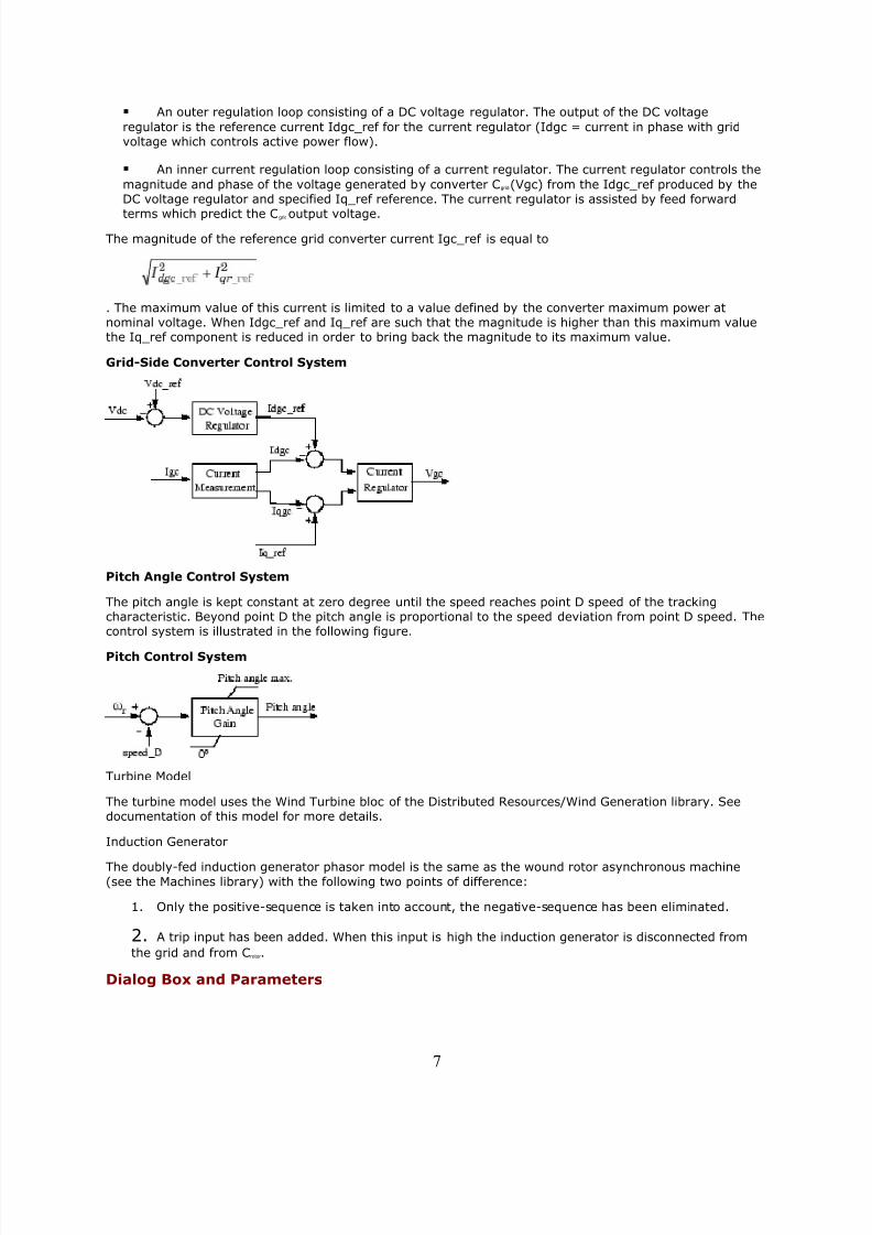
The control system, illustrated in the figure called Grid-Side Converter Control System, consists of:
Measurement systems measuring the d and q components of AC positive-sequence currents to be
controlled as well as the DC voltage Vdc.
6
8/3/2019 Wind Turbine Doubly
http://slidepdf.com/reader/full/wind-turbine-doubly 7/18
An outer regulation loop consisting of a DC voltage regulator. The output of the DC voltage
regulator is the reference current Idgc_ref for the current regulator (Idgc = current in phase with gridvoltage which controls active power flow).
An inner current regulation loop consisting of a current regulator. The current regulator controls the
magnitude and phase of the voltage generated by converter Cgrid(Vgc) from the Idgc_ref produced by theDC voltage regulator and specified Iq_ref reference. The current regulator is assisted by feed forward
terms which predict the Cgridoutput voltage.
The magnitude of the reference grid converter current Igc_ref is equal to
. The maximum value of this current is limited to a value defined by the converter maximum power atnominal voltage. When Idgc_ref and Iq_ref are such that the magnitude is higher than this maximum valuethe Iq_ref component is reduced in order to bring back the magnitude to its maximum value.
Grid-Side Converter Control System
Pitch Angle Control System
The pitch angle is kept constant at zero degree until the speed reaches point D speed of the trackingcharacteristic. Beyond point D the pitch angle is proportional to the speed deviation from point D speed. Thecontrol system is illustrated in the following figure.
Pitch Control System
Turbine Model
The turbine model uses the Wind Turbine bloc of the Distributed Resources/Wind Generation library. Seedocumentation of this model for more details.
Induction Generator
The doubly-fed induction generator phasor model is the same as the wound rotor asynchronous machine(see the Machines library) with the following two points of difference:
1. Only the positive-sequence is taken into account, the negative-sequence has been eliminated.
2. A trip input has been added. When this input is high the induction generator is disconnected from
the grid and from Crotor .
Dialog Box and Parameters
7

8/3/2019 Wind Turbine Doubly
http://slidepdf.com/reader/full/wind-turbine-doubly 8/18
The WTDFIG parameters are grouped in four categories: Generator data, Converters data, Turbine data, andControl parameters. Use the Display listbox to select which group of parameters you want to visualize.
Generator Data Parameters
WTDFIG modeled using positive-sequence only
The WTDFIG is modeled by a three-wire system using two current sources. The WTDFIG does notgenerate any zero-sequence current, but it can generate negative-sequence currents duringunbalanced system operation.
Nominal power, line-to-line voltage and frequency
The nominal power in VA, the nominal line-to-line voltage in Vrms and the nominal system
frequency in hertz.
Stator [Rs, Lls]
The stator resistance Rs and leakage inductance Lls in pu based on the generator rating.
Rotor [Rr', Llr']
The rotor resistance Rr' and leakage inductance Llr', both referred to the stator, in pu based on thegenerator rating.
Magnetizing inductance Lm
The magnetizing inductance Lm in pu based on the generator rating.
Inertia constant, friction factor and pairs of poles
Combined generator and turbine inertia constant H in seconds, combined viscous friction factor F in
pu based on the generator rating and number of pole pairs p.
8

8/3/2019 Wind Turbine Doubly
http://slidepdf.com/reader/full/wind-turbine-doubly 9/18
You may need to use your own turbine model, in order for example, to implement different powercharacteristics or to implement the shaft stiffness. Your model must then output the mechanical
torque applied to the generator shaft. If the inertia and the friction factor of the turbine areimplemented inside the turbine model you specify only the generator inertia constant H and the
generator friction factor F.
Initial conditions
The initial slip s, electrical angle Θ in degrees, stator phasor current magnitude in pu, stator phasorcurrent phase angle in degrees, rotor phasor current magnitude in pu and rotor phasor currentphase angle in degrees.
Converters Data Parameters
Converter maximum power
The maximum power of both Cgrid and Crotor in pu of the nominal power. This parameter is used tocompute the maximum current at 1 pu of voltage for Cgrid. The maximum current for Crotor is 1 pu.
Grid-side coupling inductor [L R]
The coupling inductance L and its resistance R in pu based on the generator rating.
Coupling inductor initial currents
The coupling inductor initial phasor current in positive-sequence. Enter magnitude IL in pu andphase ph_IL in degrees. If you know the initial value of the current corresponding to the WTDFIGoperating point you may specify it in order to start simulation in steady state. If you don't know this
value, you can leave [0 0]. The system will reach steady-state after a short transient.
Nominal DC bus voltage
The nominal DC bus voltage in volts.
DC bus capacitor
9
8/3/2019 Wind Turbine Doubly
http://slidepdf.com/reader/full/wind-turbine-doubly 10/18
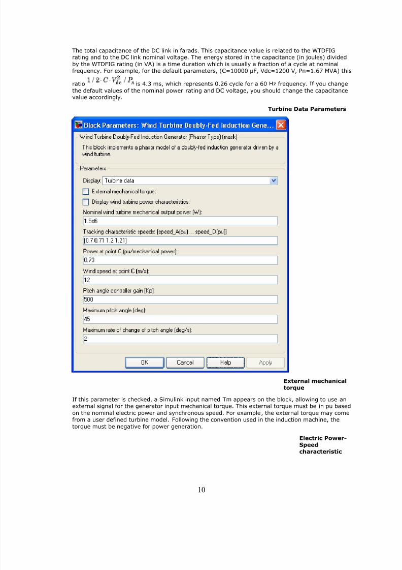
The total capacitance of the DC link in farads. This capacitance value is related to the WTDFIGrating and to the DC link nominal voltage. The energy stored in the capacitance (in joules) divided
by the WTDFIG rating (in VA) is a time duration which is usually a fraction of a cycle at nominalfrequency. For example, for the default parameters, (C=10000 µF, Vdc=1200 V, Pn=1.67 MVA) this
ratio is 4.3 ms, which represents 0.26 cycle for a 60 Hz frequency. If you change
the default values of the nominal power rating and DC voltage, you should change the capacitance
value accordingly.
Turbine Data Parameters
External mechanicaltorque
If this parameter is checked, a Simulink input named Tm appears on the block, allowing to use anexternal signal for the generator input mechanical torque. This external torque must be in pu based
on the nominal electric power and synchronous speed. For example, the external torque may comefrom a user defined turbine model. Following the convention used in the induction machine, the
torque must be negative for power generation.
Electric Power-Speedcharacteristic
10

8/3/2019 Wind Turbine Doubly
http://slidepdf.com/reader/full/wind-turbine-doubly 11/18
This parameter is visible only when the External mechanical torque parameter is checked. It isused to specify a series of speed-power pairs for the tracking characteristic. The speed is in pu
based on synchronous speed and the power is in pu based on nominal generator power.
Display
windturbinepowercharacterist
ics
If this parameter is checked, the turbine power characteristics at zero degree of pitch angle are
displayed for different wind speeds. The tracking characteristic is also displayed on the same figure.
This parameter is not visible when the External mechanical torque parameter is checked.
Nominal windturbinemecha
nicaloutput
power
This parameter is not visible when the External mechanical torque parameter is checked.
The nominal turbine mechanical output power in watts.
Tracki
ng
char
acte
risti
csp
eeds
This parameter is not visible when the External mechanical torque parameter is checked.
Specify the speeds of point A to point D of the tracking characteristic in pu of the synchronousspeed. speed_B must be greater than speed_A and speed_D must be greater than speed_C.
Power
atpo
intC
This parameter is not visible when the External mechanical torque parameter is checked.
Specify the power of point C of the tracking characteristic in pu of the Nominal wind turbine
mechanical output power.
Wind
speedat pointC
11

8/3/2019 Wind Turbine Doubly
http://slidepdf.com/reader/full/wind-turbine-doubly 12/18
This parameter is not visible when the External mechanical torque parameter is checked.
Specify wind speed in m/s for point C. The power at point C is the maximum turbine output powerfor the specified wind speed.
Pitch ancontrolgain [K
This parameter is not visible when the External mechanical torque parameter is checked.
Proportional gain Kp of the pitch controller. Specify Kp in degrees/(speed deviation pu). The speed
deviation is the difference between actual speed and speed of point D in pu of synchronous speed.
Maximu
angle
This parameter is not visible when the External mechanical torque parameter is checked.
The maximum pitch angle in degrees.
Maximu
change
This parameter is not visible when the External mechanical torque parameter is checked.
The maximum rate of change of the pitch angle in degrees/s.
Control Parameters
12

8/3/2019 Wind Turbine Doubly
http://slidepdf.com/reader/full/wind-turbine-doubly 13/18
Mode of operation
Specifies the WTDFIG mode of operation. Select either Voltage regulation or Var
regulation.
External grid voltage reference
This parameter is not visible when the Mode of operation parameter is set to Var regulation.
13
8/3/2019 Wind Turbine Doubly
http://slidepdf.com/reader/full/wind-turbine-doubly 14/18
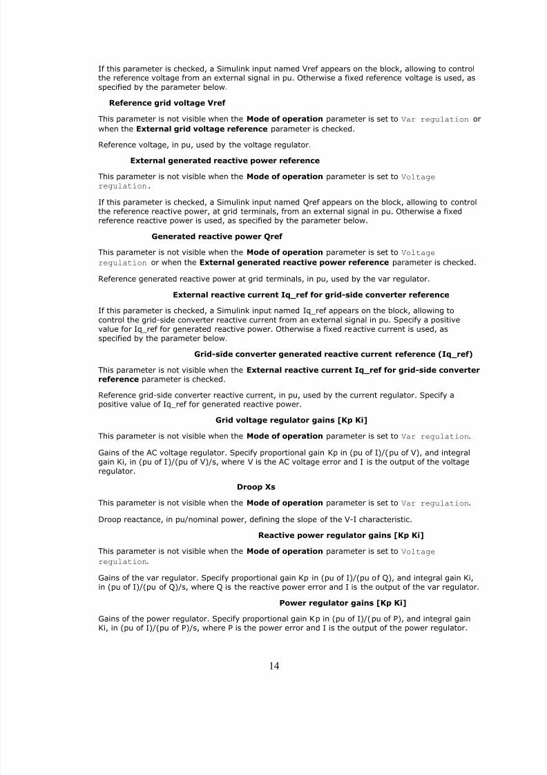
If this parameter is checked, a Simulink input named Vref appears on the block, allowing to controlthe reference voltage from an external signal in pu. Otherwise a fixed reference voltage is used, as
specified by the parameter below.
Reference grid voltage Vref
This parameter is not visible when the Mode of operation parameter is set to Var regulation or
when the External grid voltage reference parameter is checked.
Reference voltage, in pu, used by the voltage regulator.
External generated reactive power reference
This parameter is not visible when the Mode of operation parameter is set to Voltageregulation.
If this parameter is checked, a Simulink input named Qref appears on the block, allowing to controlthe reference reactive power, at grid terminals, from an external signal in pu. Otherwise a fixedreference reactive power is used, as specified by the parameter below.
Generated reactive power Qref
This parameter is not visible when the Mode of operation parameter is set to Voltage
regulation or when the External generated reactive power reference parameter is checked.
Reference generated reactive power at grid terminals, in pu, used by the var regulator.
External reactive current Iq_ref for grid-side converter reference
If this parameter is checked, a Simulink input named Iq_ref appears on the block, allowing to
control the grid-side converter reactive current from an external signal in pu. Specify a positivevalue for Iq_ref for generated reactive power. Otherwise a fixed reactive current is used, as
specified by the parameter below.
Grid-side converter generated reactive current reference (Iq_ref)
This parameter is not visible when the External reactive current Iq_ref for grid-side converterreference parameter is checked.
Reference grid-side converter reactive current, in pu, used by the current regulator. Specify a
positive value of Iq_ref for generated reactive power.
Grid voltage regulator gains [Kp Ki]
This parameter is not visible when the Mode of operation parameter is set to Var regulation.
Gains of the AC voltage regulator. Specify proportional gain Kp in (pu of I)/(pu of V), and integralgain Ki, in (pu of I)/(pu of V)/s, where V is the AC voltage error and I is the output of the voltage
regulator.
Droop Xs
This parameter is not visible when the Mode of operation parameter is set to Var regulation.
Droop reactance, in pu/nominal power, defining the slope of the V-I characteristic.
Reactive power regulator gains [Kp Ki]
This parameter is not visible when the Mode of operation parameter is set to Voltage
regulation.
Gains of the var regulator. Specify proportional gain Kp in (pu of I)/(pu of Q), and integral gain Ki,in (pu of I)/(pu of Q)/s, where Q is the reactive power error and I is the output of the var regulator.
Power regulator gains [Kp Ki]
Gains of the power regulator. Specify proportional gain Kp in (pu of I)/(pu of P), and integral gainKi, in (pu of I)/(pu of P)/s, where P is the power error and I is the output of the power regulator.
14
8/3/2019 Wind Turbine Doubly
http://slidepdf.com/reader/full/wind-turbine-doubly 15/18
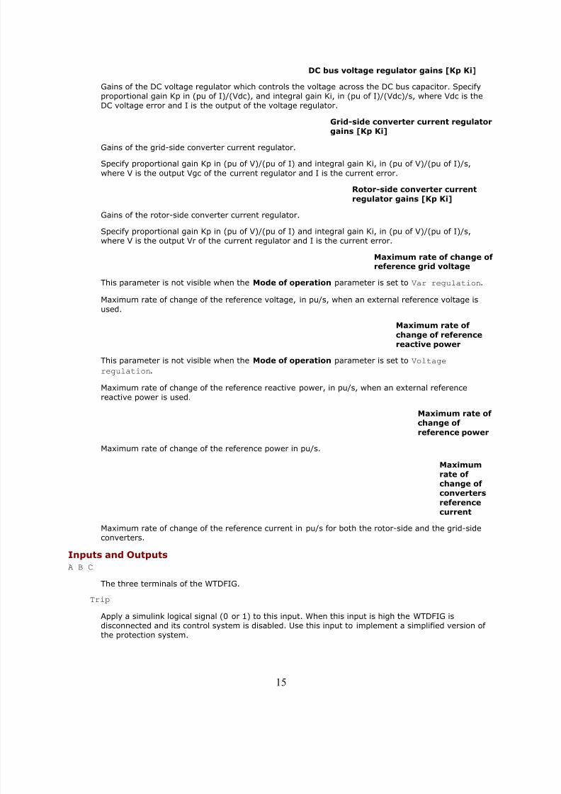
DC bus voltage regulator gains [Kp Ki]
Gains of the DC voltage regulator which controls the voltage across the DC bus capacitor. Specifyproportional gain Kp in (pu of I)/(Vdc), and integral gain Ki, in (pu of I)/(Vdc)/s, where Vdc is theDC voltage error and I is the output of the voltage regulator.
Grid-side converter current regulatorgains [Kp Ki]
Gains of the grid-side converter current regulator.
Specify proportional gain Kp in (pu of V)/(pu of I) and integral gain Ki, in (pu of V)/(pu of I)/s,
where V is the output Vgc of the current regulator and I is the current error.
Rotor-side converter current
regulator gains [Kp Ki]
Gains of the rotor-side converter current regulator.
Specify proportional gain Kp in (pu of V)/(pu of I) and integral gain Ki, in (pu of V)/(pu of I)/s,where V is the output Vr of the current regulator and I is the current error.
Maximum rate of change of reference grid voltage
This parameter is not visible when the Mode of operation parameter is set to Var regulation.
Maximum rate of change of the reference voltage, in pu/s, when an external reference voltage is
used.
Maximum rate of
change of referencereactive power
This parameter is not visible when the Mode of operation parameter is set to Voltage
regulation.
Maximum rate of change of the reference reactive power, in pu/s, when an external referencereactive power is used.
Maximum rate of change of
reference power
Maximum rate of change of the reference power in pu/s.
Maximumrate of change of converters
referencecurrent
Maximum rate of change of the reference current in pu/s for both the rotor-side and the grid-sideconverters.
Inputs and OutputsA B C
The three terminals of the WTDFIG.
Trip
Apply a simulink logical signal (0 or 1) to this input. When this input is high the WTDFIG isdisconnected and its control system is disabled. Use this input to implement a simplified version of the protection system.
15
8/3/2019 Wind Turbine Doubly
http://slidepdf.com/reader/full/wind-turbine-doubly 16/18
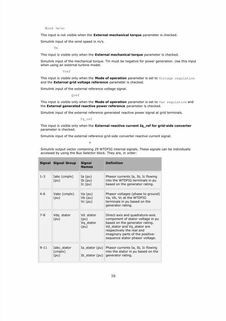
Wind (m/s)
This input is not visible when the External mechanical torque parameter is checked.
Simulink input of the wind speed in m/s.
Tm
This input is visible only when the External mechanical torque parameter is checked.Simulink input of the mechanical torque. Tm must be negative for power generation. Use this inputwhen using an external turbine model.
Vref
This input is visible only when the Mode of operation parameter is set to Voltage regulation
and the External grid voltage reference parameter is checked.
Simulink input of the external reference voltage signal.
Qref
This input is visible only when the Mode of operation parameter is set to Var regulation and
the External generated reactive power reference parameter is checked.
Simulink input of the external reference generated reactive power signal at grid terminals.
Iq_ref
This input is visible only when the External reactive current Iq_ref for grid-side converterparameter is checked.
Simulink input of the external reference grid-side converter reactive current signal.
m
Simulink output vector containing 29 WTDFIG internal signals. These signals can be individuallyaccessed by using the Bus Selector block. They are, in order:
Signal Signal Group Signal
Names
Definition
1-3 Iabc (cmplx)
(pu)
Ia (pu)
Ib (pu)Ic (pu)
Phasor currents Ia, Ib, Ic flowing
into the WTDFIG terminals in pubased on the generator rating.
4-6 Vabc (cmplx)(pu)
Va (pu)Vb (pu)
Vc (pu)
Phasor voltages (phase to ground)Va, Vb, Vc at the WTDFIG
terminals in pu based on thegenerator rating.
7-8 Vdq_stator(pu)
Vd_stator(pu)
Vq_stator(pu)
Direct-axis and quadrature-axiscomponent of stator voltage in pu
based on the generator rating.Vd_stator and Vq_stator arerespectively the real andimaginary parts of the positive-
sequence stator phasor voltage.
9-11 Iabc_stator
(cmplx)(pu)
Ia_stator (pu)
Ib_stator (pu)
Phasor currents Ia, Ib, Ic flowing
into the stator in pu based on thegenerator rating.
16
8/3/2019 Wind Turbine Doubly
http://slidepdf.com/reader/full/wind-turbine-doubly 17/18
Signal Signal Group Signal
Names
Definition
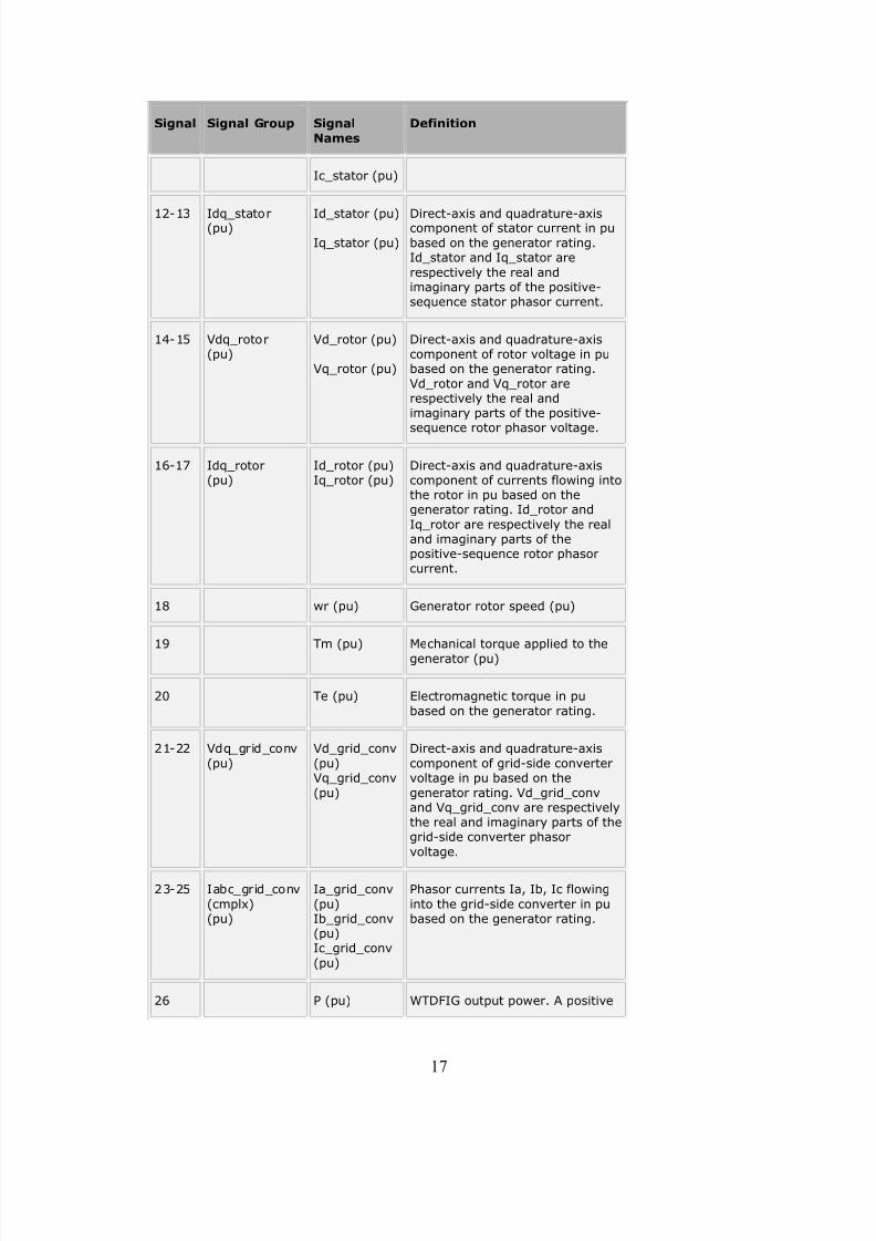
Ic_stator (pu)
12-13 Idq_stator(pu) Id_stator (pu)
Iq_stator (pu)
Direct-axis and quadrature-axiscomponent of stator current in pu
based on the generator rating.Id_stator and Iq_stator are
respectively the real andimaginary parts of the positive-sequence stator phasor current.
14-15 Vdq_rotor(pu)
Vd_rotor (pu)
Vq_rotor (pu)
Direct-axis and quadrature-axiscomponent of rotor voltage in pubased on the generator rating.
Vd_rotor and Vq_rotor arerespectively the real andimaginary parts of the positive-sequence rotor phasor voltage.
16-17 Idq_rotor(pu)
Id_rotor (pu)Iq_rotor (pu)
Direct-axis and quadrature-axiscomponent of currents flowing intothe rotor in pu based on thegenerator rating. Id_rotor and
Iq_rotor are respectively the realand imaginary parts of thepositive-sequence rotor phasorcurrent.
18 wr (pu) Generator rotor speed (pu)
19 Tm (pu) Mechanical torque applied to the
generator (pu)
20 Te (pu) Electromagnetic torque in pu
based on the generator rating.
21-22 Vdq_grid_conv
(pu)
Vd_grid_conv
(pu)Vq_grid_conv
(pu)
Direct-axis and quadrature-axis
component of grid-side convertervoltage in pu based on the
generator rating. Vd_grid_convand Vq_grid_conv are respectivelythe real and imaginary parts of thegrid-side converter phasor
voltage.
23-25 Iabc_grid_conv
(cmplx)(pu)
Ia_grid_conv
(pu)Ib_grid_conv(pu)Ic_grid_conv
(pu)
Phasor currents Ia, Ib, Ic flowing
into the grid-side converter in pubased on the generator rating.
26 P (pu) WTDFIG output power. A positive
17

8/3/2019 Wind Turbine Doubly
http://slidepdf.com/reader/full/wind-turbine-doubly 18/18
Signal Signal Group Signal
Names
Definition
value indicates power generation.
27
Q (pu) WTDFIG output reactive power. Apositive value indicates reactive
power generation.
28 Vdc (V) DC voltage (V).
29 Pitch_angle(deg)
Blade pitch angle in degrees.
Example
See the power_wind_dfig demo which illustrates the steady-state and dynamic performance of the
WTDFIG in a 9 MW Wind Farm connected on a 25 kV, 60 Hz, system.
References[1] R. Pena, J.C. Clare, G.M. Asher, "Doubly fed induction generator using back-to-back PWM converters and
its application to variable-speed wind-energy generation," IEEE Proc.-Electr. Power Appl., Vol. 143, No. 3,May 1996
[2] Vladislav Akhmatov, "Variable-Speed Wind Turbines with Doubly-Fed Induction Generators, Part I:Modelling in Dynamic Simulation Tools," Wind Engineering Volume 26, No. 2, 2002
[3] Nicholas W. Miller, Juan J. Sanchez-Gasca, William W. Price, Robert W. Delmerico, "DYNAMIC MODELINGOF GE 1.5 AND 3.6 MW WIND TURBINE-GENERATORS FOR STABILITY SIMULATIONS," GE Power Systems
Energy Consulting, IEEE WTG Modeling Panel, Session July 2003
18


![[PhD 2003] [for NEG Micon Control Systems] Doubly Fed Drives for Variable Speed Wind Turbine](https://img.pdfslide.us/doc/110x75/577ce40f1a28abf1038d9c56/phd-2003-for-neg-micon-control-systems-doubly-fed-drives-for-variable-speed.jpg)