Embed Size (px)
DESCRIPTION
Â
Citation preview

Prepared by: Eng. Ahmed Zaaza
•Wimax is a IEEE 802.16 standard.
•So, What is the 802?
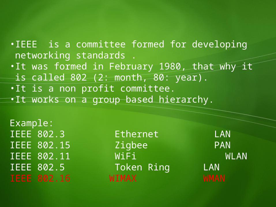
• IEEE is a committee formed for developing networking standards .
• It was formed in February 1980, that why it is called 802 (2: month, 80: year).
• It is a non profit committee.• It works on a group based hierarchy.
Example: IEEE 802.3 Ethernet LANIEEE 802.15 Zigbee PANIEEE 802.11 WiFi WLANIEEE 802.5 Token Ring LANIEEE 802.16 WIMAX WMAN
IEEE 802.15 Bluetooth
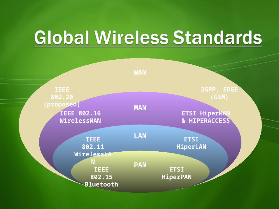
WAN
MAN
LAN
PAN ETSI HiperPAN
IEEE 802.11 WirelessLAN
ETSI HiperLAN
IEEE 802.16 WirelessMAN
ETSI HiperMAN & HIPERACCESS
IEEE 802.20(proposed)
3GPP, EDGE (GSM)
Application
Presentation
Session
Transport
Network
Data Link
Physical
77
66
55
44
33
22
11
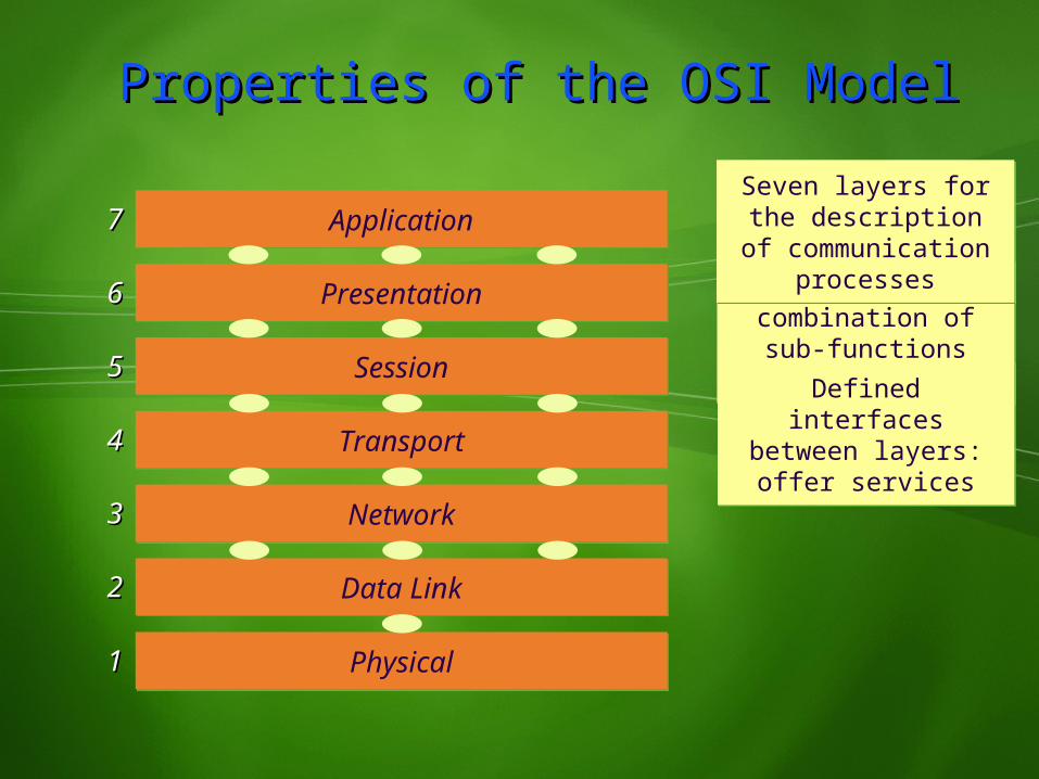
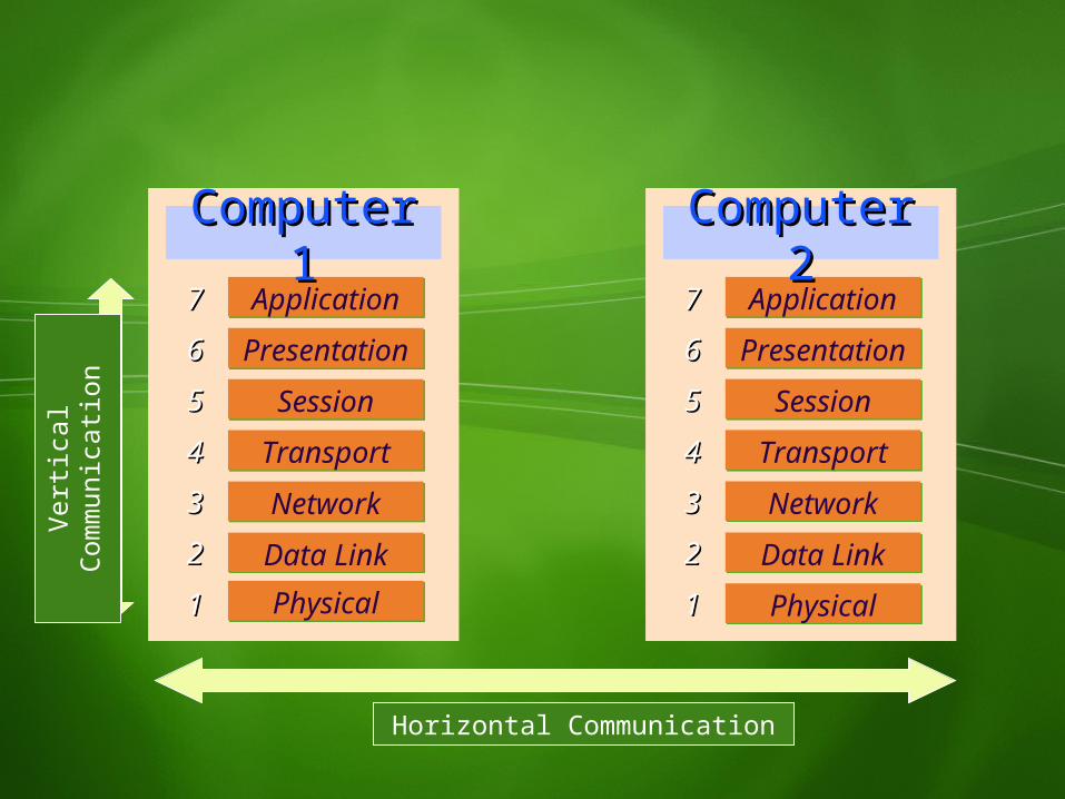
Logical combination of sub-functions within
one layerDefined interfaces between layers:offer services
Seven layers for the description of
communication processes
Properties of the OSI ModelProperties of the OSI Model
Application
Presentation
Session
Transport
Network
Data LinkPhysical
77
66
55
44
33
22
11
Computer 1Computer 1Application
Presentation
Session
Transport
Network
Data Link
Physical
77
66
55
44
33
22
11
Computer 2Computer 2
Horizontal Communication
Verti
cal
Com
mun
icatio
n
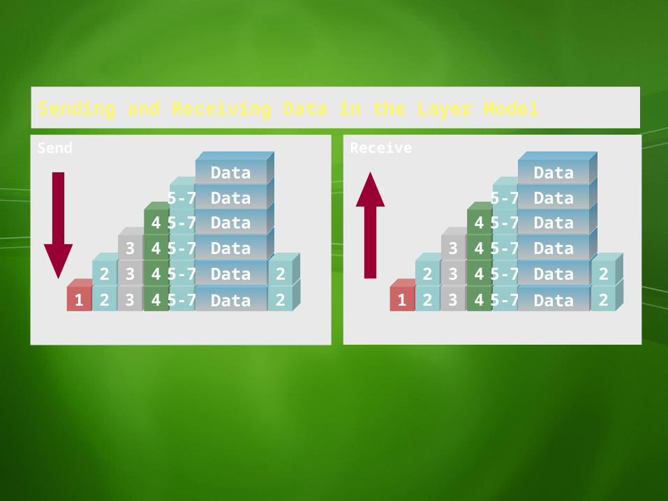
Sending and Receiving Data in the Layer Model
Send Receive
1 2 3 4 5-7 Data 22 3 4 5-7 Data 2
3 4 5-7 Data4 5-7 Data
5-7 DataData
1 2 3 4 5-7 Data 22 3 4 5-7 Data 2
3 4 5-7 Data4 5-7 Data
5-7 DataData
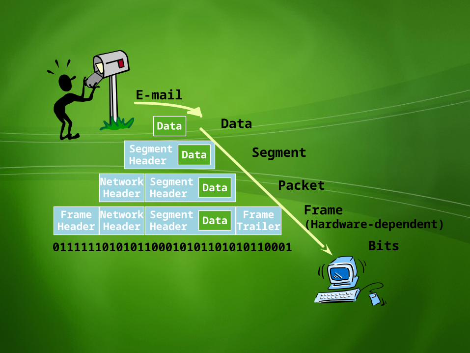
Network Header
SegmentHeader
FrameTrailerData
SegmentHeader Data
Data
FrameHeader
NetworkHeader
SegmentHeader Data
0111111010101100010101101010110001
Data
Segment
PacketFrame(Hardware-dependent)
Bits
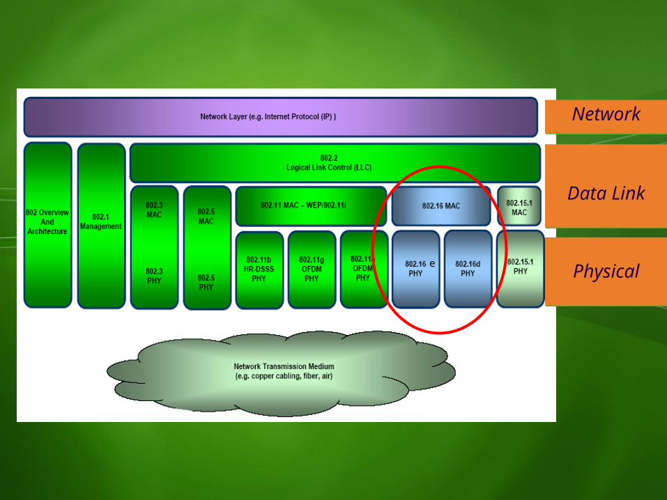
Network
Data Link
Physicale
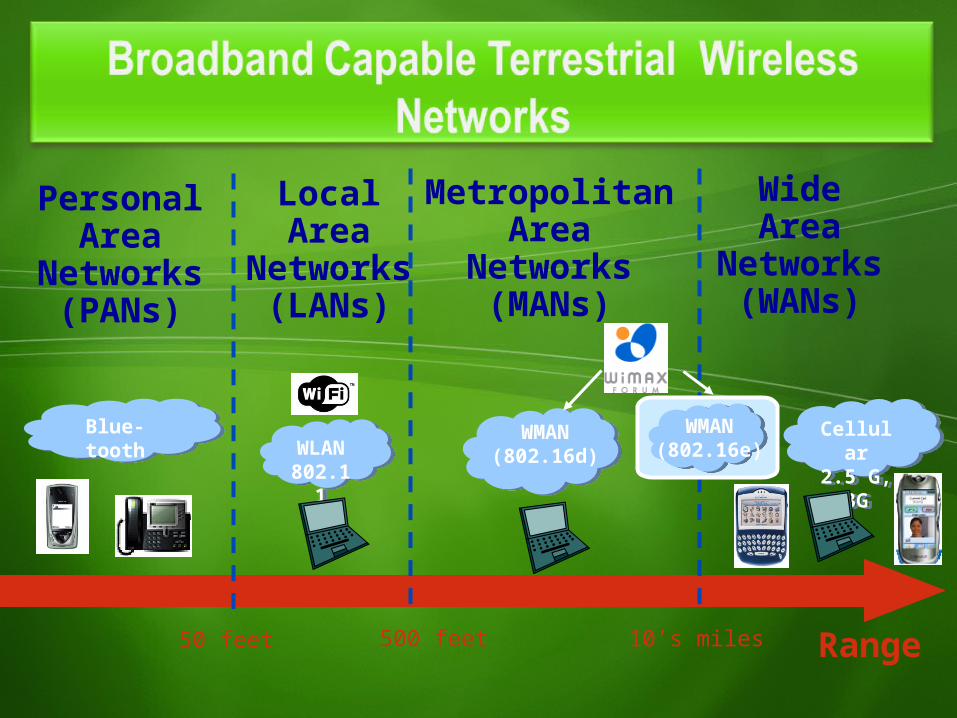
Blue-tooth
PersonalArea
Networks(PANs)
Range50 feet 500 feet 10’s miles
MetropolitanArea
Networks(MANs)
WLAN
802.11
LocalArea
Networks(LANs)
WideArea
Networks(WANs)
Cellular
2.5 G, 3G
WMAN(802.16d)
WMAN(802.16e)
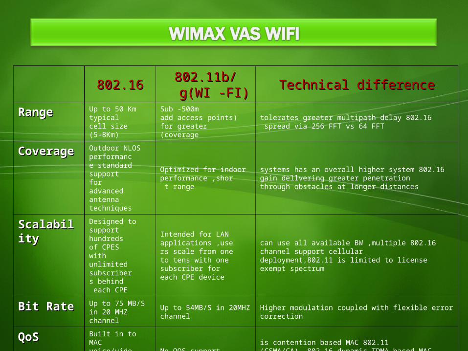
802.16802.16 802.11b/g(WI 802.11b/g(WI -FI)-FI) Technical differenceTechnical difference
RangeRange Up to 50 Km typical cell size
(5-8Km)
Sub -500m(add access points for greater
coverage)
802.16 tolerates greater multipath delay spread via 256 FFT vs 64 FFT
CoverageCoverage Outdoor NLOS performance standard support for advanced antenna techniques
Optimized for indoor performance ,short range
802.16 systems has an overall higher system gain dellvering greater penetration through obstacles at longer distances
ScalabilityScalability Designed to support hundreds of CPES with unlimited subscribers behind each CPE
Intended for LAN applications ,users scale from one to tens with one subscriber for each CPE device
802.16 can use all available BW ,multiple channel support cellular deployment,802.11 is limited to license exempt spectrum
Bit RateBit Rate Up to 75 MB/S in 20 MHZ channel
Up to 54MB/S in 20MHZ channel Higher modulation coupled with flexible error correction
QoSQoS Built in to MAC voice/video service levels
No QOS support 802.11 is contention based MAC )CSMA/CA( ,802.16 dynamic TDMA-based MAC with on-demand BW allocation
MACMAC Polling –based MAC layer Contention based MAC
• In 1998, the Institute of Electrical and Electronics Engineers (IEEE) formed a group called 802.16 to develop a standard for what was called a wireless metropolitan area network, or wireless MAN. Originally, this group focused on developing solutions in the 10GHz to 66GHz band.
• IEEE 802.16The IEEE 802.16 group produced a standard that was approved in
December 2001. This standard, Wireless MAN-SC, specified a physical layer that used single-carrier modulation techniques and a media access control (MAC) layer with a burst time division multiplexing (TDM) structure that supported both frequency division duplexing (FDD) and time division duplexing (TDD).
• IEEE 802.16a (OFDM)After completing this standard, the group started work on extending
and modifying it to work in both licensed and license-exempt frequencies in the 2GHz to 11GHz range, which would enable NLOS deployments. This amendment, IEEE 802.16a, was completed in 2003.
•IEEE 802.16-2004 (Fixed & Portable)Further revisions to 802.16a were made and completed in 2004. This revised standard, IEEE 802.16-2004, replaces 802.16, 802.16a with a single standard, which has also been adopted as the basis for HIPERMAN (high-performance metropolitan area network) by ETSI (European Telecommunications Standards Institute). •IEEE 802.16e (Mobile)In 2003, the 802.16 group began work on enhancements to the specifications to allow vehicular mobility applications.The 802.16e, was completed in December 2005 and was published formally as IEEE 802.16e-2005.It specifies scalable OFDM for the physical layer and makes further modifications to the MAC layer to accommodate high-speed mobility.
• As it turns out, the IEEE 802.16 specifications are a collection of standards with a very broad scope. In order to accommodate the diverse needs of the industry, the standard incorporated a wide variety of options. In order to develop interoperable solutions using the 802.16 family of standards, the scope of the standard had to be reduced by establishing consensus on what options of the standard to implement and test for interoperability. The IEEE developed the specifications but left to the industry the task of converting them into an interoperable standard that can be certified. The WiMAX Forum was formed to solve this problem and to promote solutions based on the IEEE 802.16 standards.
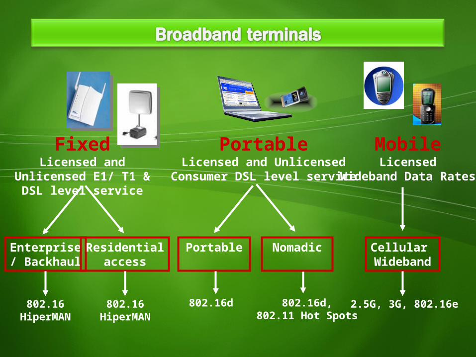
FixedLicensed and
Unlicensed E1/ T1 & DSL level service
PortableLicensed and Unlicensed
Consumer DSL level service
MobileLicensed
Wideband Data Rates
802.16HiperMA
N
Enterprise/ Backhaul
802.16HiperMAN
Residentialaccess
Nomadic Cellular Wideband
2.5G, 3G, 802.16e
Portable
802.16d,802.11 Hot Spots
802.16d
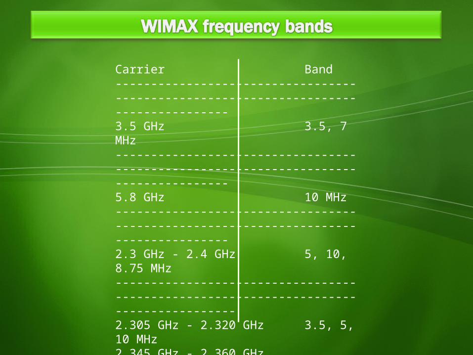
Carrier Band------------------------------------------------------------------------------------3.5 GHz 3.5, 7 MHz------------------------------------------------------------------------------------5.8 GHz 10 MHz------------------------------------------------------------------------------------2.3 GHz - 2.4 GHz 5, 10, 8.75 MHz-------------------------------------------------------------------------------------2.305 GHz - 2.320 GHz 3.5, 5, 10 MHz2.345 GHz - 2.360 GHz-------------------------------------------------------------------------------------2.496 GHz - 2.69 GHz 5, 10 MHz-------------------------------------------------------------------------------------3.3 GHz – 3.4 GHz 5, 7, 10 MHz-------------------------------------------------------------------------------------3.4 GHz – 3.8 GHz 5, 7, 10 MHz3.4 GHz – 3.6 GHz3.6 GHz – 3.8 GHz
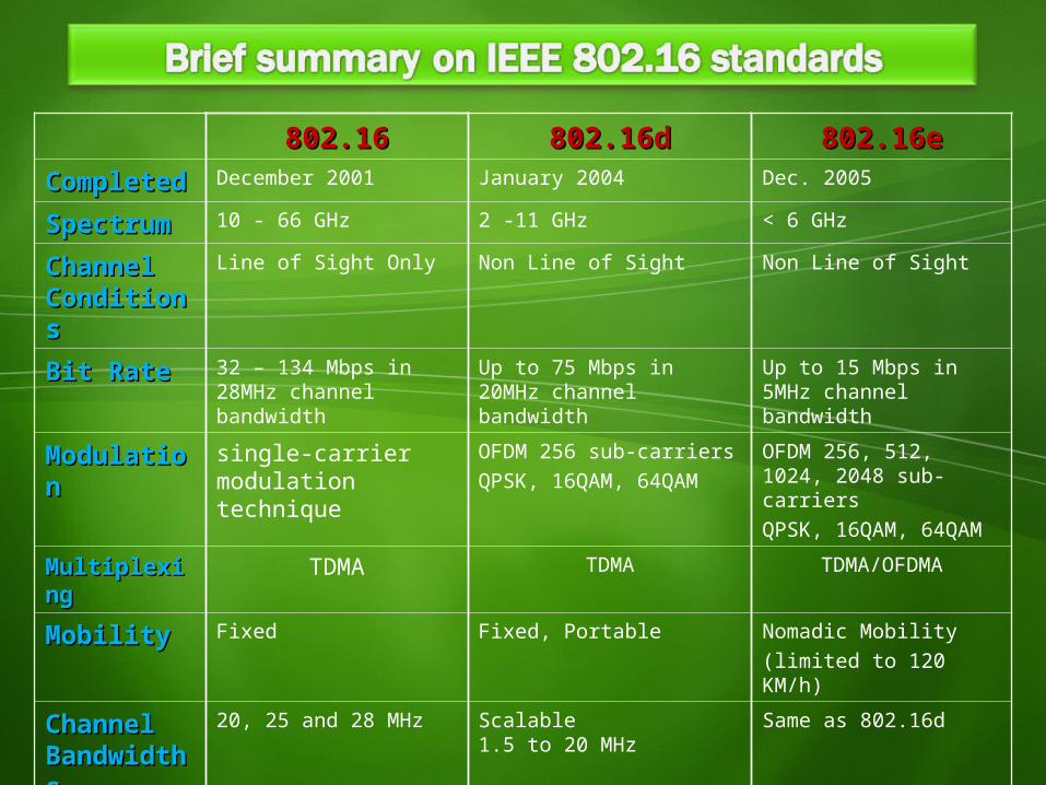
802.16802.16 802.16d802.16d 802.16e802.16eCompletedCompleted December 2001 January 2004 Dec. 2005
SpectrumSpectrum 10 - 66 GHz 2 -11 GHz < 6 GHz
Channel Channel ConditionsConditions
Line of Sight Only Non Line of Sight Non Line of Sight
Bit RateBit Rate 32 – 134 Mbps in 28MHz channel bandwidth
Up to 75 Mbps in 20MHz channel bandwidth
Up to 15 Mbps in 5MHz channel bandwidth
ModulationModulation single-carrier modulation technique
OFDM 256 sub-carriersQPSK, 16QAM, 64QAM
OFDM 256, 512, 1024, 2048 sub-carriersQPSK, 16QAM, 64QAM
MultiplexingMultiplexing TDMA TDMA TDMA/OFDMA
MobilityMobility Fixed Fixed, Portable Nomadic Mobility(limited to 120 KM/h)
Channel Channel BandwidthsBandwidths
20, 25 and 28 MHz Scalable1.5 to 20 MHz
Same as 802.16d
Typical Cell Typical Cell RadiusRadius
2-5 km 7 to 10 km(Max range 50 km for backhauling)
2-5 km
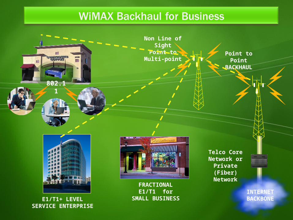
Point to Point
BACKHAUL
INTERNETBACKBON
E
Telco Core Network or
Private (Fiber)
Network
Non Line of Sight
Point to Multi-point
FRACTIONAL E1/T1 for
SMALL BUSINESS
802.11
E1/T1+ LEVELSERVICE ENTERPRISE
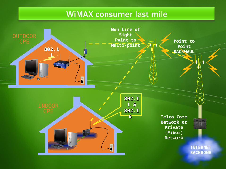
INTERNETBACKBON
E
Telco Core Network or
Private (Fiber)
Network
Non Line of Sight
Point to Multi-point
OUTDOORCPE
INDOORCPE
802.1802.111
Point to Point
BACKHAUL
802.1802.11 & 1 &
802.1802.16 6
BSBSBSBS
BSBSBSBS
ASN-GWASN-GW
ASN-GWASN-GWCSNCSN
Internet Internet Or Or
IP-networkIP-networkMSMS
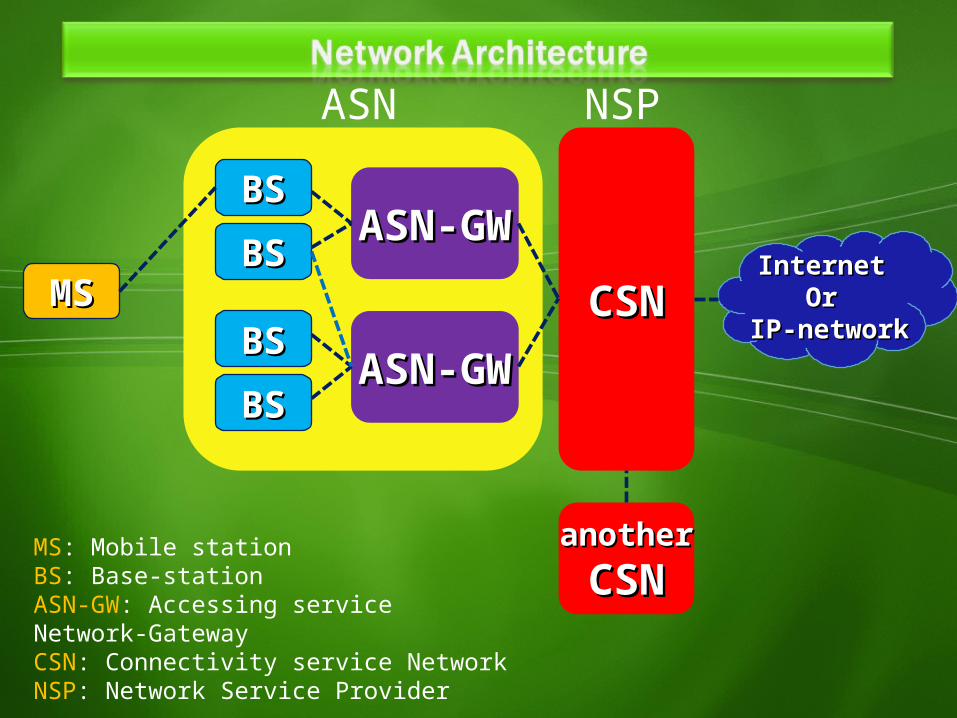
ASN NSP
anotheranotherCSNCSN
MS: Mobile stationBS: Base-stationASN-GW: Accessing service Network-GatewayCSN: Connectivity service NetworkNSP: Network Service Provider
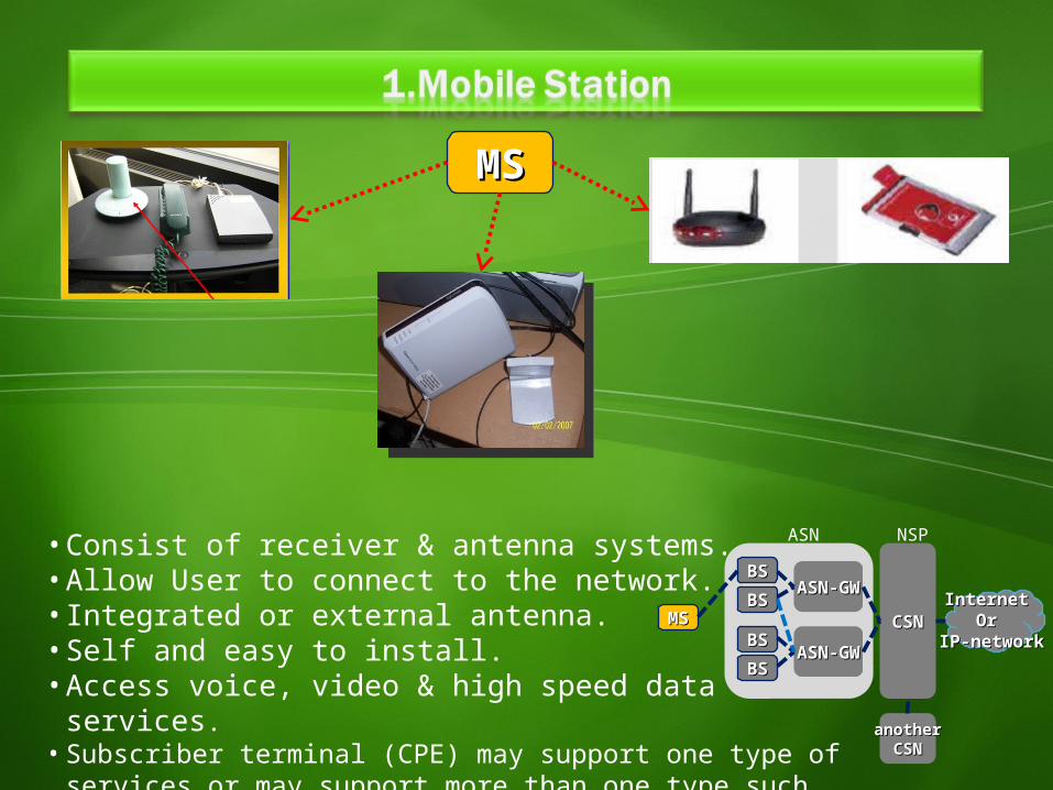
• Consist of receiver & antenna systems. • Allow User to connect to the network.• Integrated or external antenna.• Self and easy to install.• Access voice, video & high speed data services.• Subscriber terminal (CPE) may support one type of
services or may support more than one type such as (Voice, Video & Data).
MSMS
BSBSBSBS
BSBSBSBS
ASN-GWASN-GW
ASN-GWASN-GWCSNCSN
Internet Internet Or Or
IP-networkIP-networkMSMS
ASN
NSP
anotheranotherCSNCSN
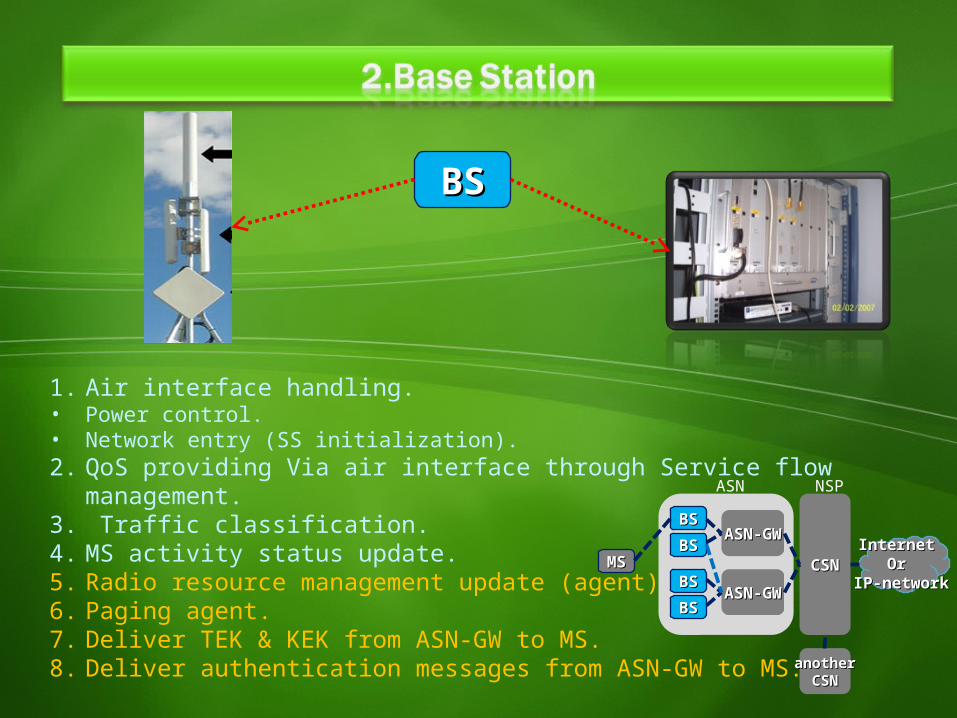
1. Air interface handling.• Power control.• Network entry (SS initialization).2. QoS providing Via air interface through Service flow management.3. Traffic classification.4. MS activity status update.5. Radio resource management update (agent).6. Paging agent.7. Deliver TEK & KEK from ASN-GW to MS.8. Deliver authentication messages from ASN-GW to MS.
BSBS
BSBSBSBS
BSBSBSBS
ASN-GWASN-GW
ASN-GWASN-GWCSNCSN
Internet Internet Or Or
IP-networkIP-networkMSMS
ASN
NSP
anotheranotherCSNCSN
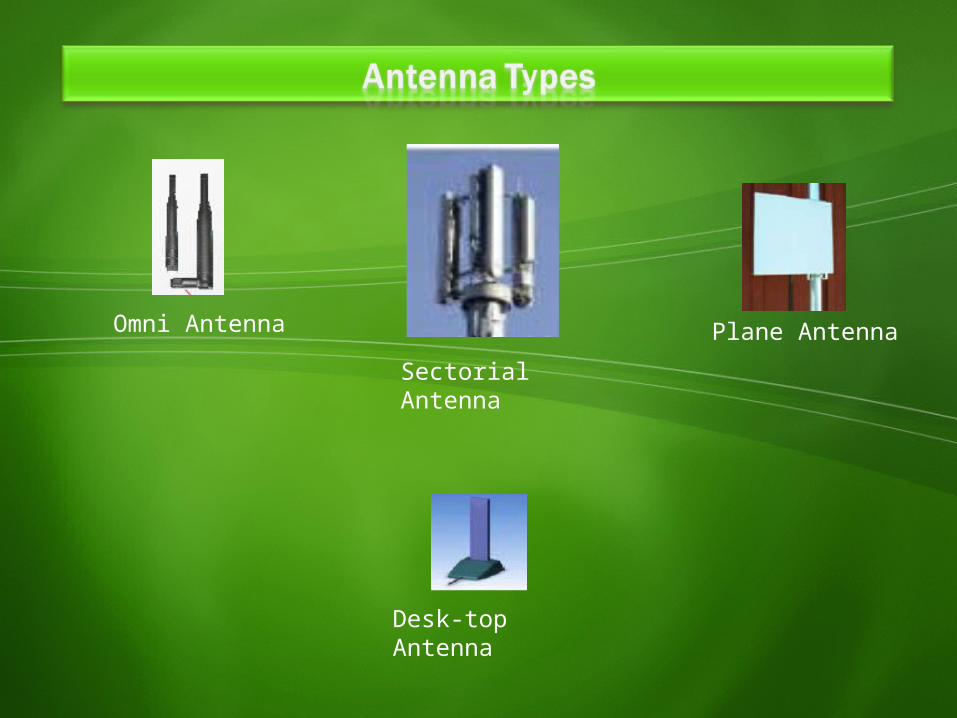
Sectorial Antenna
Omni Antenna Plane Antenna
Desk-top Antenna
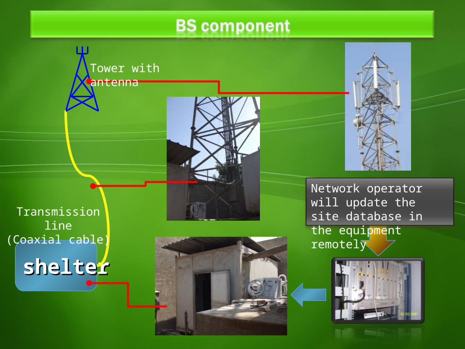
sheltershelter
Tower with antenna
Transmission line(Coaxial cable)
Network operator will update the site database in the equipment remotely
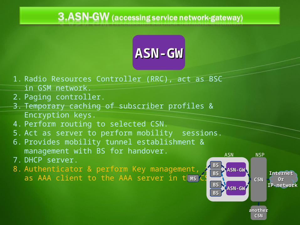
ASN-GWASN-GW1. Radio Resources Controller (RRC), act as BSC in GSM
network.2. Paging controller.3. Temporary caching of subscriber profiles &
Encryption keys.4. Perform routing to selected CSN.5. Act as server to perform mobility sessions.6. Provides mobility tunnel establishment &
management with BS for handover.7. DHCP server.8. Authenticator & perform Key management, act as
AAA client to the AAA server in the CSN.BSBSBSBS
BSBSBSBS
ASN-GWASN-GW
ASN-GWASN-GWCSNCSN
Internet Internet Or Or
IP-networkIP-networkMSMS
ASN
NSP
anotheranotherCSNCSN
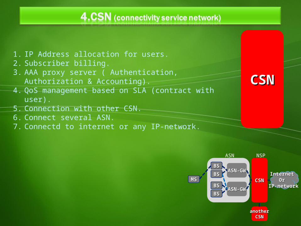
CSNCSN
1. IP Address allocation for users.2. Subscriber billing.3. AAA proxy server ( Authentication, Authorization &
Accounting).4. QoS management based on SLA (contract with user).5. Connection with other CSN.6. Connect several ASN.7. Connectd to internet or any IP-network.
BSBSBSBS
BSBSBSBS
ASN-GWASN-GW
ASN-GWASN-GWCSNCSN
Internet Internet Or Or
IP-networkIP-networkMSMS
ASN
NSP
anotheranotherCSNCSN
Simultaneously support hundreds of businesses with E1/T1 Simultaneously support hundreds of businesses with E1/T1 speed connectivity and thousands of homes with DSL speed speed connectivity and thousands of homes with DSL speed connectivity. connectivity.
Promise of potential low cost and flexibility in building Promise of potential low cost and flexibility in building broadband networks.broadband networks.
Scalability, as extra channels and base stations can be Scalability, as extra channels and base stations can be added incrementally as bandwidth demand grows.added incrementally as bandwidth demand grows.
Support for both voice and video as well as Internet data.Support for both voice and video as well as Internet data.
Semiconductor vendors envisage WiMax-enabled chips Semiconductor vendors envisage WiMax-enabled chips appearing in PCs in 2006 and in notebook computers and appearing in PCs in 2006 and in notebook computers and PDAs by 2007PDAs by 2007
ATM OverviewAsynchronous transfer mode
ATM OverviewATM Overview• Developed to carry multimedia real-Developed to carry multimedia real-
time application (video - speech) and time application (video - speech) and non real-time application (data)non real-time application (data)
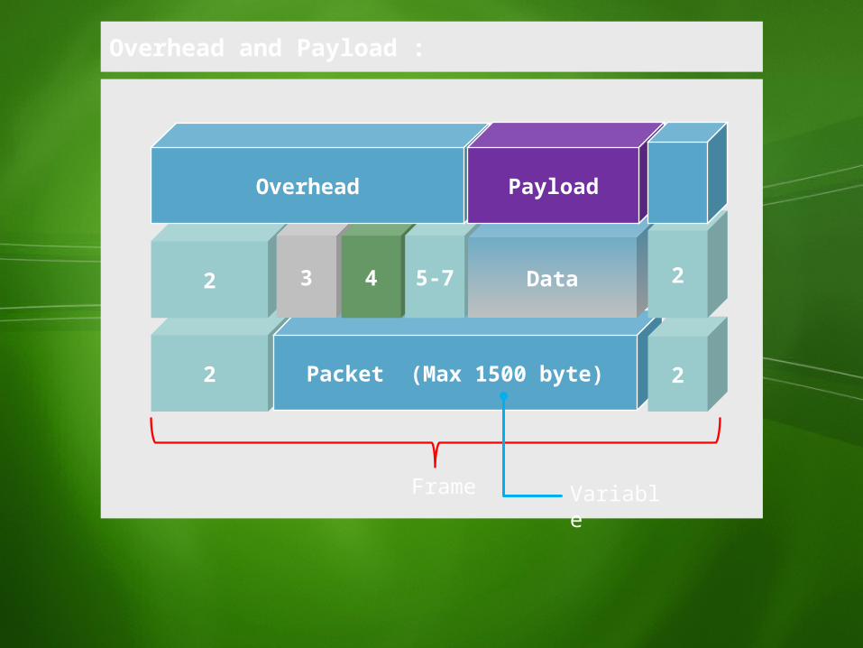
2 Packet (Max 1500 byte)
Overhead and Payload :
2 3 4 5-7 Data
Overhead Payload
2
2
Frame Variable

What is the problem?
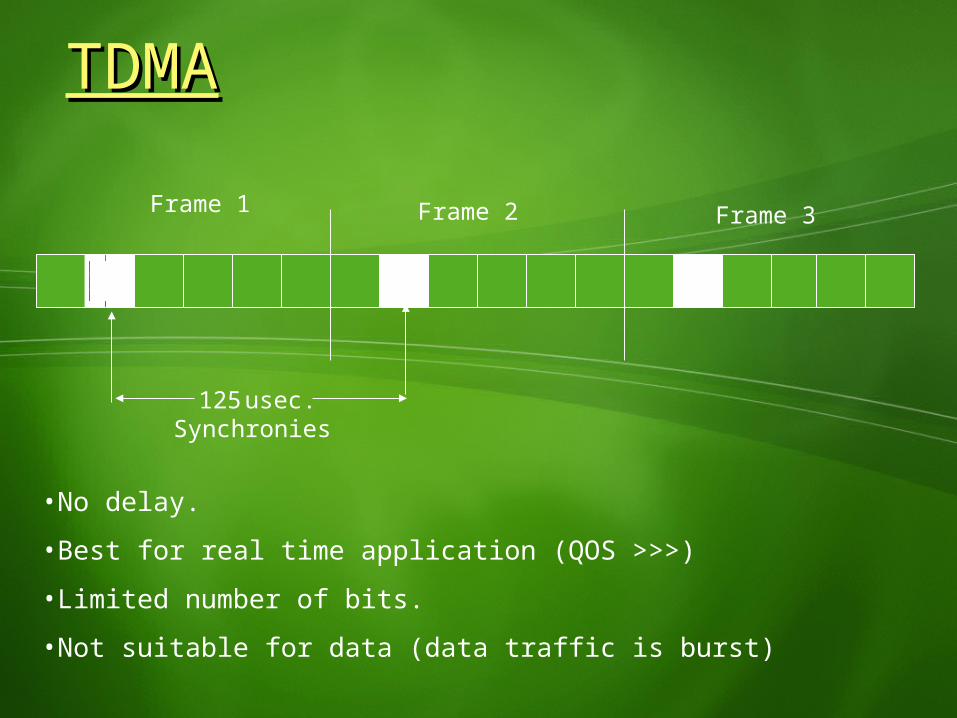
125 usec. Synchronies
Frame 1 Frame 2 Frame 3
•No delay.•Best for real time application (QOS >>>)•Limited number of bits.•Not suitable for data (data traffic is burst)
TDMATDMA
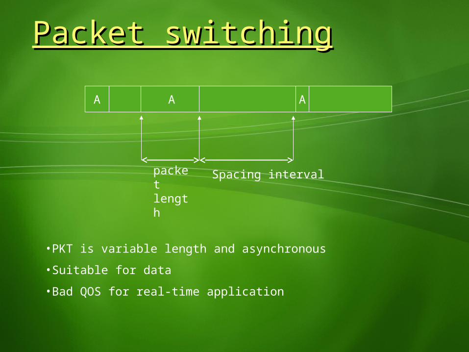
A A A
•PKT is variable length and asynchronous•Suitable for data•Bad QOS for real-time application
Packet switchingPacket switching
Spacing intervalpacketlength
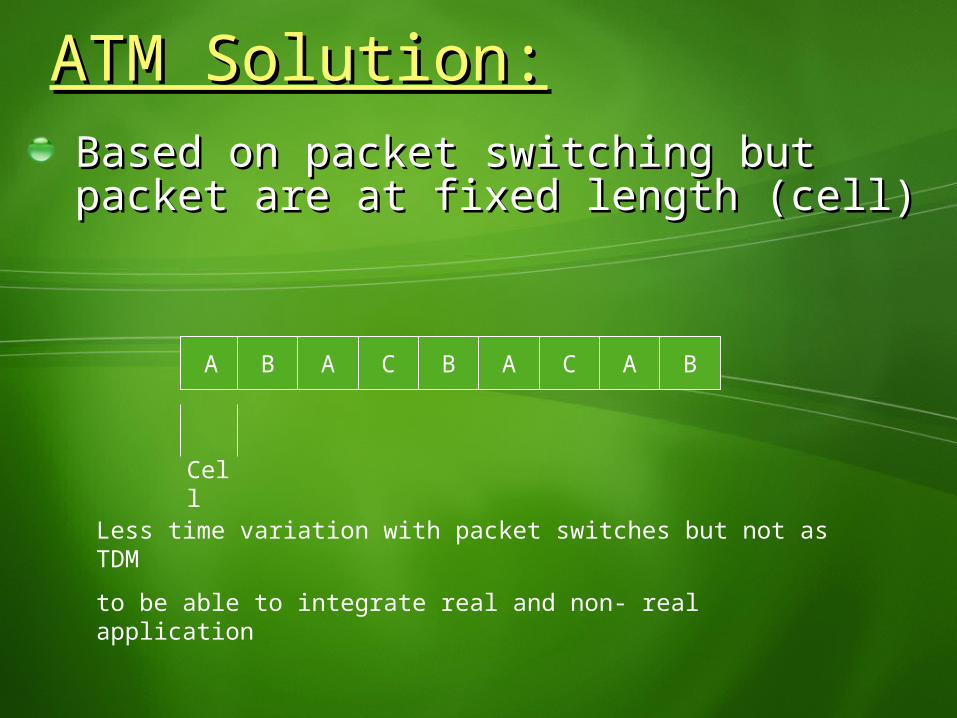
ATM Solution:ATM Solution:Based on packet switching but packet Based on packet switching but packet are at fixed length (cell)are at fixed length (cell)
A B A C B A C A B
Cell
Less time variation with packet switches but not as TDMto be able to integrate real and non- real application
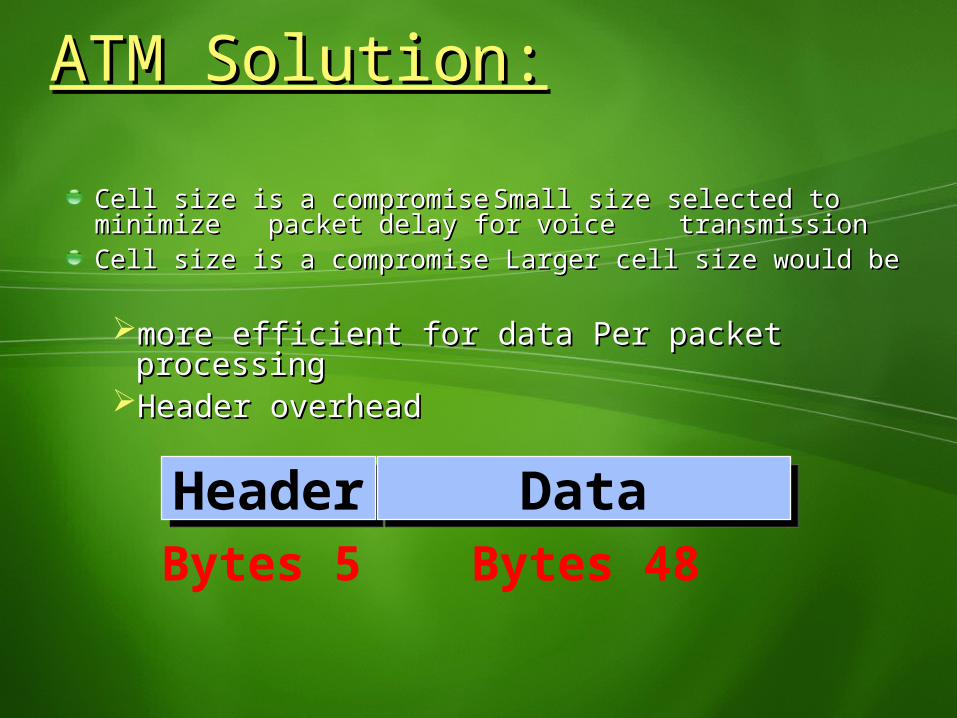
Cell size is a compromiseCell size is a compromise Small size selected to minimize Small size selected to minimize packet delay for voice transmissionpacket delay for voice transmission Cell size is a compromise Larger cell size would beCell size is a compromise Larger cell size would be
more efficient for data Per packet processingmore efficient for data Per packet processingHeader overheadHeader overhead
Header DataBytes 5 Bytes 48
ATM Solution:ATM Solution:
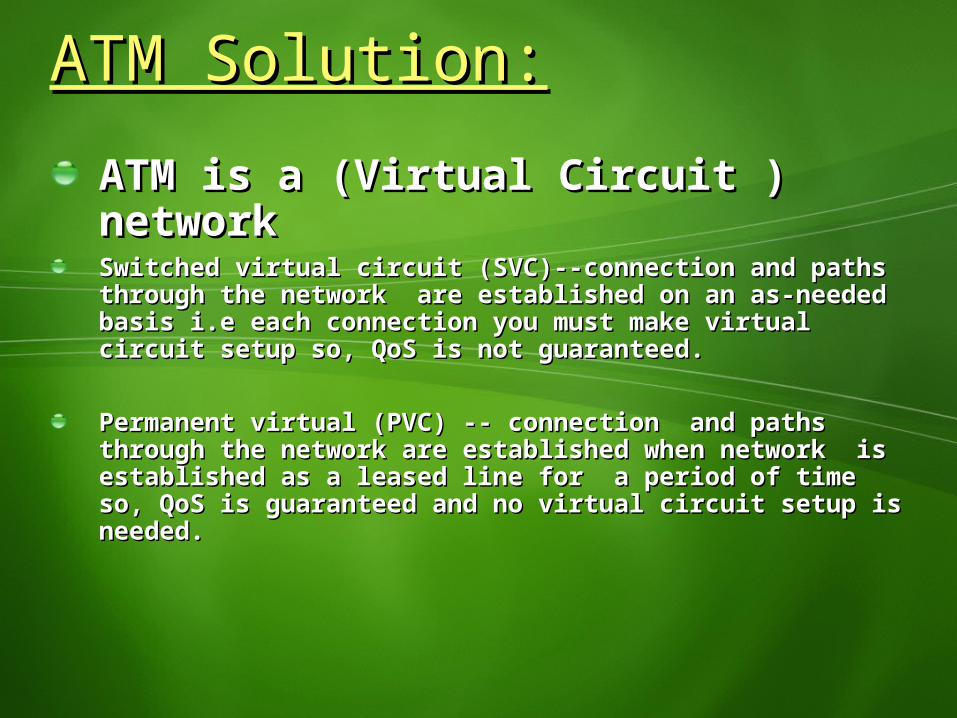
ATM is a (Virtual Circuit ) ATM is a (Virtual Circuit ) networknetworkSwitched virtual circuit (SVC)--connection and paths Switched virtual circuit (SVC)--connection and paths through the network are established on an as-needed through the network are established on an as-needed basis i.e each connection you must make virtual circuit basis i.e each connection you must make virtual circuit setup so, QoS is not guaranteed.setup so, QoS is not guaranteed.
Permanent virtual (PVC) -- connection and paths Permanent virtual (PVC) -- connection and paths through the network are established when network is through the network are established when network is established as a leased line for a period of time so, QoS established as a leased line for a period of time so, QoS is guaranteed and no virtual circuit setup is needed.is guaranteed and no virtual circuit setup is needed.
ATM Solution:ATM Solution:
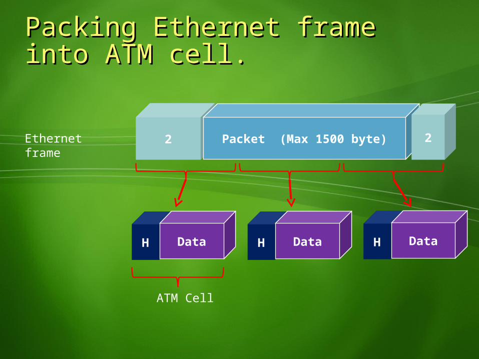
2 Packet (Max 1500 byte) 2
H Data H Data H Data
ATM Cell
Packing Ethernet frame into Packing Ethernet frame into ATM cell.ATM cell.
Ethernet frame
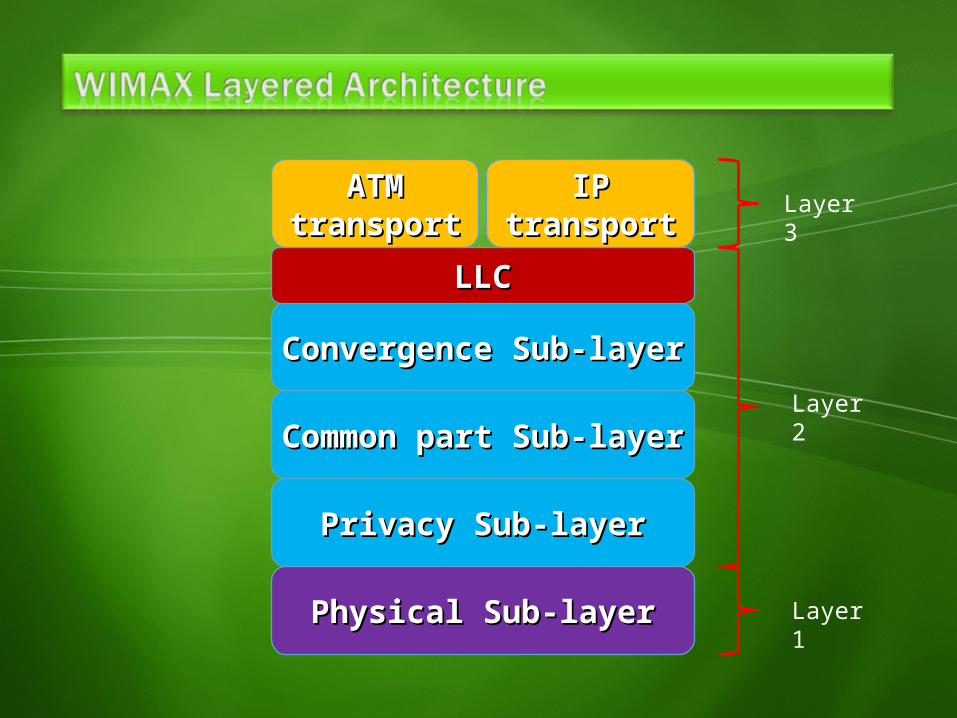
ATMATMtransporttransport
IPIPtransporttransport
Convergence Sub-layerConvergence Sub-layer
Common part Sub-layerCommon part Sub-layer
Privacy Sub-layerPrivacy Sub-layer
Physical Sub-layerPhysical Sub-layer
LLCLLC
Layer 3
Layer 2
Layer 1
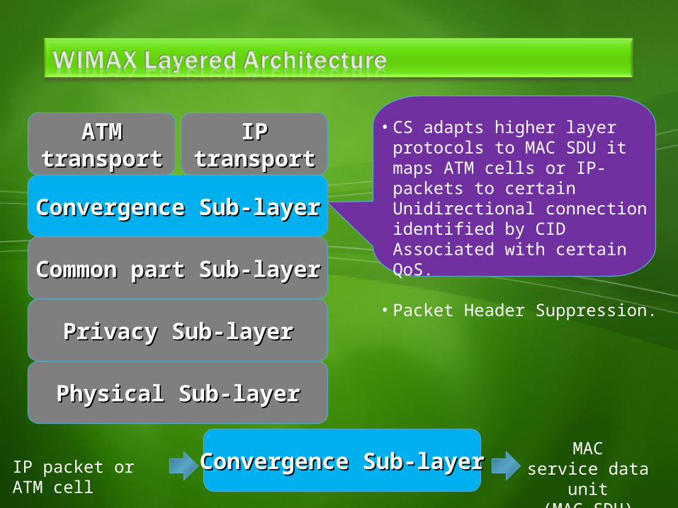
IP packet or ATM cell
MACservice data unit
(MAC SDU)
ATMATMtransporttransport
IPIPtransporttransport
Convergence Sub-layerConvergence Sub-layer
Common part Sub-layerCommon part Sub-layer
Privacy Sub-layerPrivacy Sub-layer
Physical Sub-layerPhysical Sub-layer
Convergence Sub-layerConvergence Sub-layer
• CS adapts higher layer protocols to MAC SDU it maps ATM cells or IP-packets to certain Unidirectional connection identified by CID Associated with certain QoS.
• Packet Header Suppression.
ATMATMtransporttransport
IPIPtransporttransport
Convergence Sub-layerConvergence Sub-layer
Common part Sub-layerCommon part Sub-layer
Privacy Sub-layerPrivacy Sub-layer
Physical Sub-layerPhysical Sub-layer
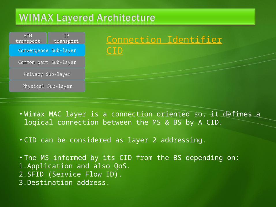
Connection Identifier CID
• Wimax MAC layer is a connection oriented so, it defines a logical connection between the MS & BS by A CID.
• CID can be considered as layer 2 addressing.
• The MS informed by its CID from the BS depending on:1.Application and also QoS.2.SFID (Service Flow ID).3.Destination address.

ATMATMtransporttransport
IPIPtransporttransport
Convergence Sub-layerConvergence Sub-layer
Common part Sub-layerCommon part Sub-layer
Privacy Sub-layerPrivacy Sub-layer
Physical Sub-layerPhysical Sub-layer
PHS (Packet Header Suppression)• Convergence sub-layer do PHS to decreas the
data overhead on the packet and its repeating according to the PHS rule.
PHSM come from the PHS rule
PHSI
PacketPacketHeaderHeader
PacketPacketMAC SDUMAC SDU
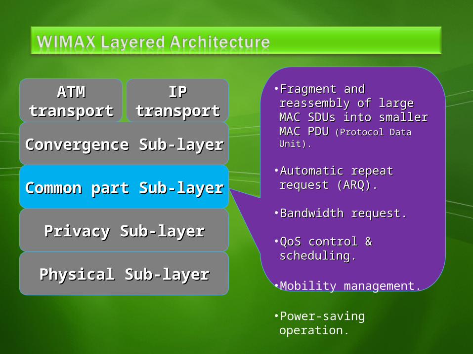
• Fragment and reassembly Fragment and reassembly of large MAC SDUs into of large MAC SDUs into smaller MAC PDUsmaller MAC PDU (Protocol (Protocol Data Unit).Data Unit).
• Automatic repeat request Automatic repeat request (ARQ).(ARQ).
• Bandwidth request.Bandwidth request.
• QoS control & scheduling.QoS control & scheduling.
• Mobility management.
• Power-saving operation.
ATMATMtransporttransport
IPIPtransporttransport
Convergence Sub-layerConvergence Sub-layer
Common part Sub-layerCommon part Sub-layer
Privacy Sub-layerPrivacy Sub-layer
Physical Sub-layerPhysical Sub-layer
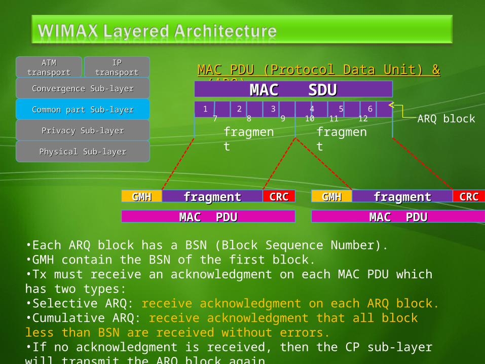
MAC PDU (Protocol Data Unit) & MAC PDU (Protocol Data Unit) & (ARQ)(ARQ)
ATMATMtransporttransport
IPIPtransporttransport
Convergence Sub-layerConvergence Sub-layer
Common part Sub-layerCommon part Sub-layer
Privacy Sub-layerPrivacy Sub-layer
Physical Sub-layerPhysical Sub-layer
MAC SDUMAC SDU1 2 3 4 5 6 7 8 9 10 11 12
fragment
fragment
fragmentfragmentGMHGMH fragmentfragmentGMHGMH
ARQ block
•Each ARQ block has a BSN (Block Sequence Number).•GMH contain the BSN of the first block.•Tx must receive an acknowledgment on each MAC PDU which has two types:•Selective ARQ: receive acknowledgment on each ARQ block.•Cumulative ARQ: receive acknowledgment that all block less than BSN are received without errors.•If no acknowledgment is received, then the CP sub-layer will transmit the ARQ block again.
CRCCRC CRCCRCMAC PDUMAC PDU MAC PDUMAC PDU
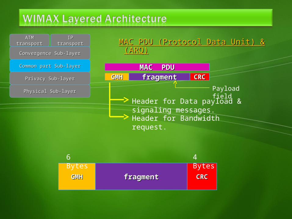
MAC PDU (Protocol Data Unit) & MAC PDU (Protocol Data Unit) & (ARQ)(ARQ)
ATMATMtransporttransport
IPIPtransporttransport
Convergence Sub-layerConvergence Sub-layer
Common part Sub-layerCommon part Sub-layer
Privacy Sub-layerPrivacy Sub-layer
Physical Sub-layerPhysical Sub-layer
fragmentfragmentGMHGMH CRCCRCMAC PDUMAC PDU
Payload fieldHeader for Data payload & signaling
messages.Header for Bandwidth request.
fragmentfragmentGMHGMH CRCCRC
6 Bytes
4 Bytes
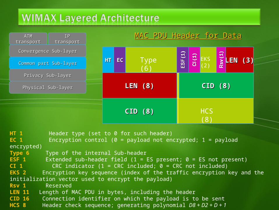
MAC PDU Header for DataMAC PDU Header for DataATMATMtransporttransport
IPIPtransporttransport
Convergence Sub-layerConvergence Sub-layer
Common part Sub-layerCommon part Sub-layer
Privacy Sub-layerPrivacy Sub-layer
Physical Sub-layerPhysical Sub-layer
HTHT ECEC Type (6)
CID (8) HCS (8)
EKS (2)
CID (8)CID (8)
CID (8)CID (8)
LEN (8)LEN (8)
LEN (3)LEN (3)
HT 1 Header type (set to 0 for such header)EC 1 Encryption control (0 = payload not encrypted; 1 = payload encrypted)Type 6 Type of the internal Sub-headerESF 1 Extended sub-header field (1 = ES present; 0 = ES not present)CI 1 CRC indicator (1 = CRC included; 0 = CRC not included)EKS 2 Encryption key sequence (index of the traffic encryption key and the initialization vector used to encrypt the payload)Rsv 1 ReservedLEN 11 Length of MAC PDU in bytes, including the headerCID 16 Connection identifier on which the payload is to be sentHCS 8 Header check sequence; generating polynomial D8 + D2 + D + 1
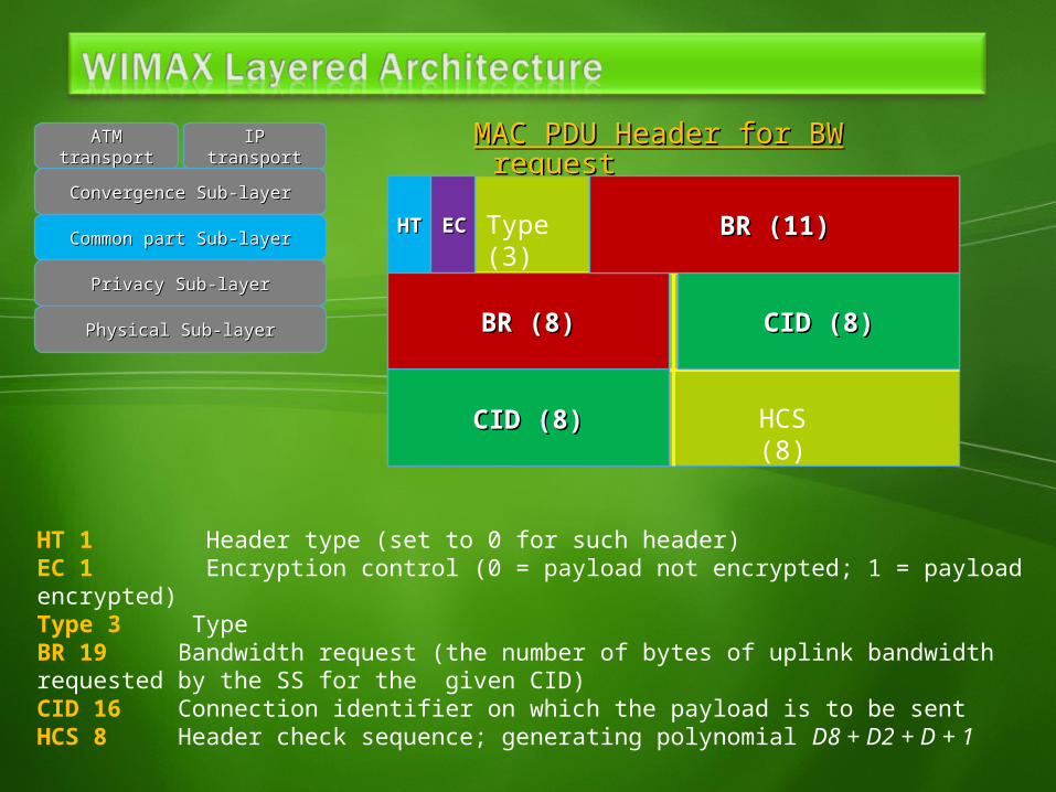
MAC PDU Header for BW MAC PDU Header for BW requestrequest
ATMATMtransporttransport
IPIPtransporttransport
Convergence Sub-layerConvergence Sub-layer
Common part Sub-layerCommon part Sub-layer
Privacy Sub-layerPrivacy Sub-layer
Physical Sub-layerPhysical Sub-layer
HTHT ECEC Type (3)
CID (8) HCS (8)
CID (8)CID (8)
CID (8)CID (8)
BR (8)BR (8)
BR (11)BR (11)
HT 1 Header type (set to 0 for such header)EC 1 Encryption control (0 = payload not encrypted; 1 = payload encrypted)Type 3 TypeBR 19 Bandwidth request (the number of bytes of uplink bandwidth requested by the SS for the given CID)CID 16 Connection identifier on which the payload is to be sentHCS 8 Header check sequence; generating polynomial D8 + D2 + D + 1
MAC PDU (Protocol Data Unit) sub-MAC PDU (Protocol Data Unit) sub-headerheader
ATMATMtransporttransport
IPIPtransporttransport
Convergence Sub-layerConvergence Sub-layer
Common part Sub-layerCommon part Sub-layer
Privacy Sub-layerPrivacy Sub-layer
Physical Sub-layerPhysical Sub-layer
PayloadPayloadGMHGMH CRCCRC
MAC PDUMAC PDU
SHSH
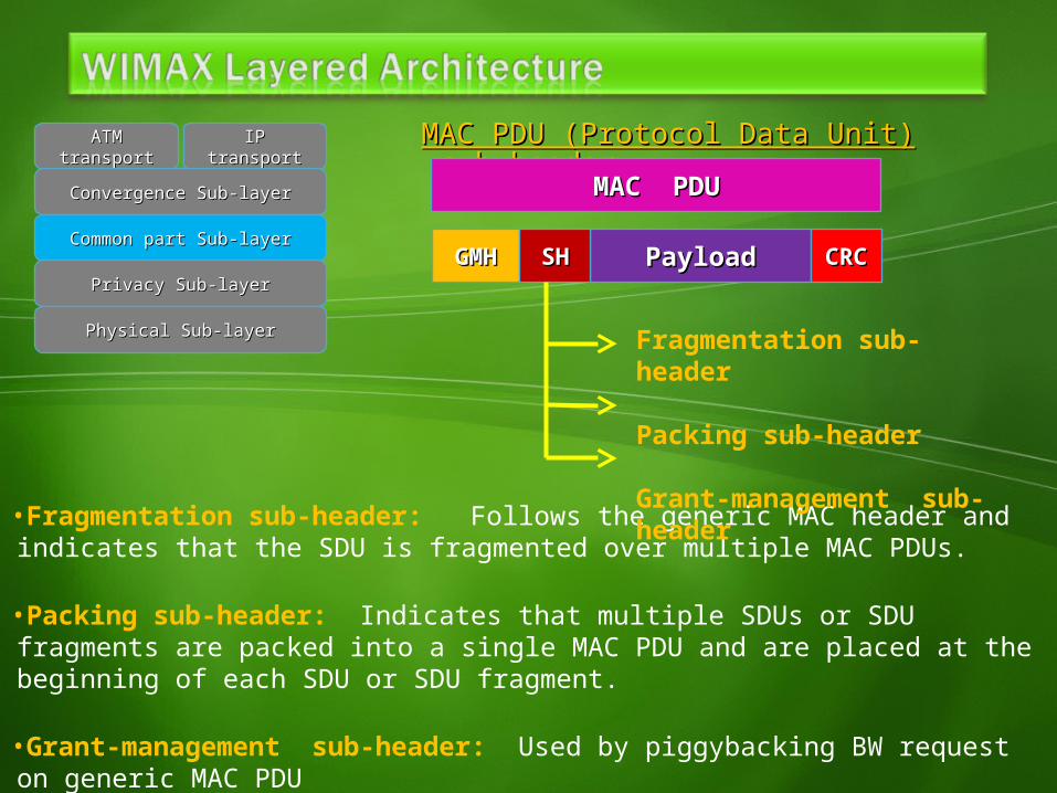
•Fragmentation sub-header: Follows the generic MAC header and indicates that the SDU is fragmented over multiple MAC PDUs.
•Packing sub-header: Indicates that multiple SDUs or SDU fragments are packed into a single MAC PDU and are placed at the beginning of each SDU or SDU fragment.
•Grant-management sub-header: Used by piggybacking BW request on generic MAC PDU
Fragmentation sub-header
Packing sub-header
Grant-management sub-header
Bandwidth Bandwidth requestrequest
ATMATMtransporttransport
IPIPtransporttransport
Convergence Sub-layerConvergence Sub-layer
Common part Sub-layerCommon part Sub-layer
Privacy Sub-layerPrivacy Sub-layer
Physical Sub-layerPhysical Sub-layer
BW requestBW requestGMHGMH CRCCRC
GMHGMH
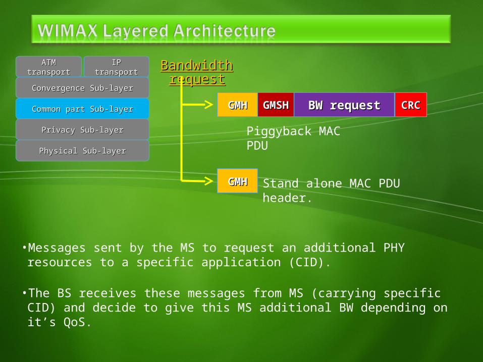
Piggyback MAC PDU
Stand alone MAC PDU header.
• Messages sent by the MS to request an additional PHY resources to a specific application (CID).
• The BS receives these messages from MS (carrying specific CID) and decide to give this MS additional BW depending on it’s QoS.
GMSHGMSH
Bandwidth Bandwidth requestrequest
ATMATMtransporttransport
IPIPtransporttransport
Convergence Sub-layerConvergence Sub-layer
Common part Sub-layerCommon part Sub-layer
Privacy Sub-layerPrivacy Sub-layer
Physical Sub-layerPhysical Sub-layer
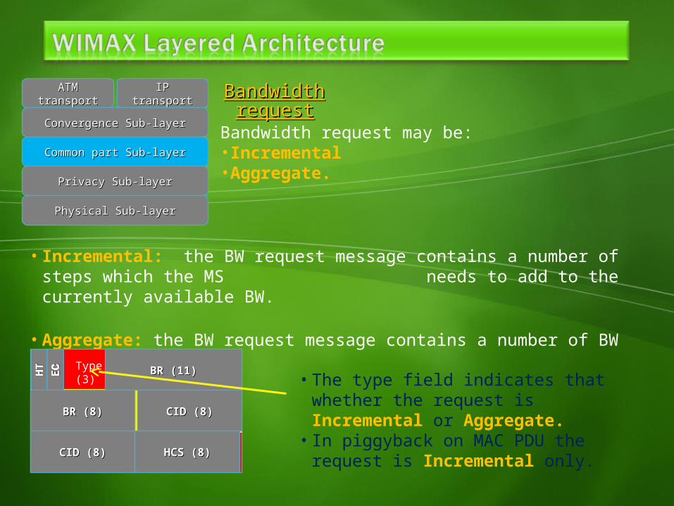
• Incremental: the BW request message contains a number of steps which the MS needs to add to the currently available BW.
• Aggregate: the BW request message contains a number of BW which the MS needs.
Bandwidth request may be:• Incremental• Aggregate.
Type (3)
HCS (8)
CID (8)CID (8)
CID (8)CID (8)
BR (8)BR (8)
BR (11)BR (11)
HCS (8)HCS (8)
• The type field indicates that whether the request is Incremental or Aggregate.
• In piggyback on MAC PDU the request is Incremental only.
Bandwidth request mechanismBandwidth request mechanismATMATMtransporttransport
IPIPtransporttransport
Convergence Sub-layerConvergence Sub-layer
Common part Sub-layerCommon part Sub-layer
Privacy Sub-layerPrivacy Sub-layer
Physical Sub-layerPhysical Sub-layer
BS
MS
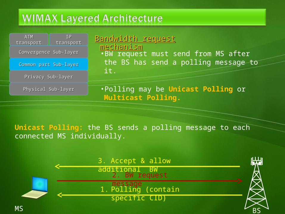
1. Polling (contain specific CID)
• BW request must send from MS after the BS has send a polling message to it.
• Polling may be Unicast Polling or Multicast Polling.
2. BW request message
3. Accept & allow additional BW
Unicast Polling: the BS sends a polling message to each connected MS individually.
BS
MS1
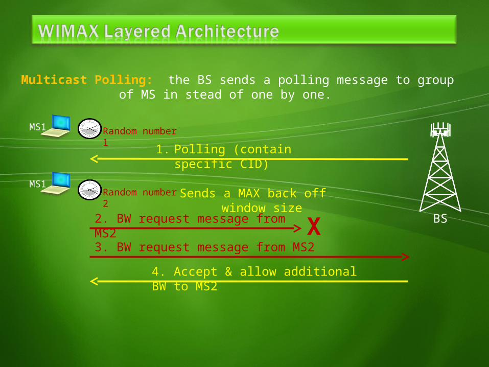
1. Polling (contain specific CID)
Sends a MAX back off window size
2. BW request message from MS2
4. Accept & allow additional BW to MS2
Multicast Polling: the BS sends a polling message to group of MS in stead of one by one.
MS1
Random number 1
Random number 2
X3. BW request message from MS2
QoS control & scheduling QoS control & scheduling ATMATMtransporttransport
IPIPtransporttransport
Convergence Sub-layerConvergence Sub-layer
Common part Sub-layerCommon part Sub-layer
Privacy Sub-layerPrivacy Sub-layer
Physical Sub-layerPhysical Sub-layer
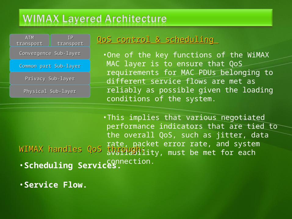
• One of the key functions of the WiMAX MAC layer is to ensure that QoS requirements for MAC PDUs belonging to different service flows are met as reliably as possible given the loading conditions of the system.
• This implies that various negotiated performance indicators that are tied to the overall QoS, such as jitter, data rate, packet error rate, and system availability, must be met for each connection.
WIMAX handles QoS through:WIMAX handles QoS through:• Scheduling Services.
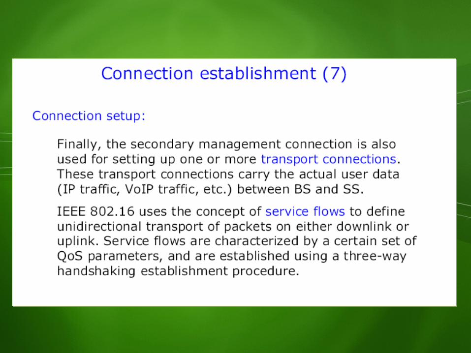
• Service Flow.
QoS Scheduling Services.ATMATMtransporttransport
IPIPtransporttransport
Convergence Sub-layerConvergence Sub-layer
Common part Sub-layerCommon part Sub-layer
Privacy Sub-layerPrivacy Sub-layer
Physical Sub-layerPhysical Sub-layer
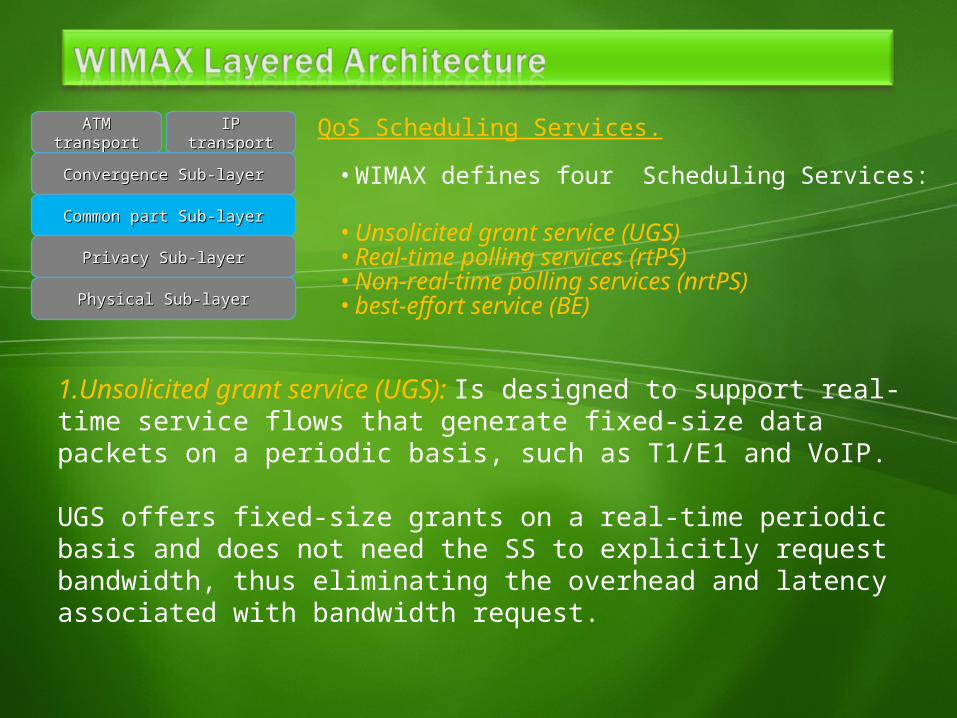
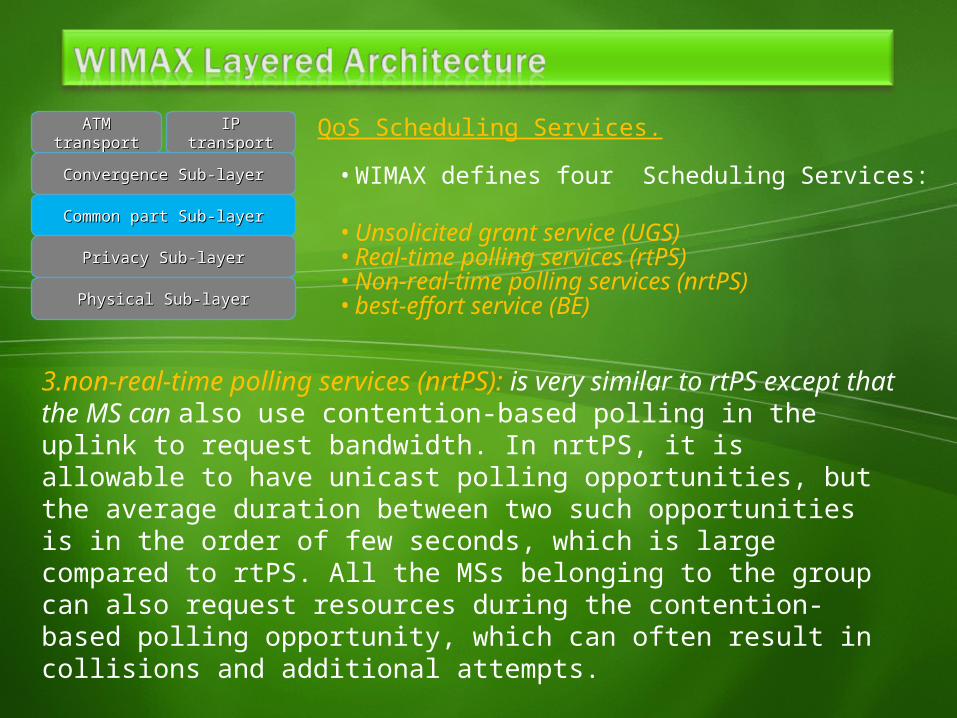
• WIMAX defines four Scheduling Services:• Unsolicited grant service (UGS)• Real-time polling services (rtPS)• Non-real-time polling services (nrtPS)• best-effort service (BE)
1.Unsolicited grant service (UGS): Is designed to support real-time service flows that generate fixed-size data packets on a periodic basis, such as T1/E1 and VoIP.
UGS offers fixed-size grants on a real-time periodic basis and does not need the SS to explicitly request bandwidth, thus eliminating the overhead and latency associated with bandwidth request.
QoS Scheduling Services.ATMATMtransporttransport
IPIPtransporttransport
Convergence Sub-layerConvergence Sub-layer
Common part Sub-layerCommon part Sub-layer
Privacy Sub-layerPrivacy Sub-layer
Physical Sub-layerPhysical Sub-layer
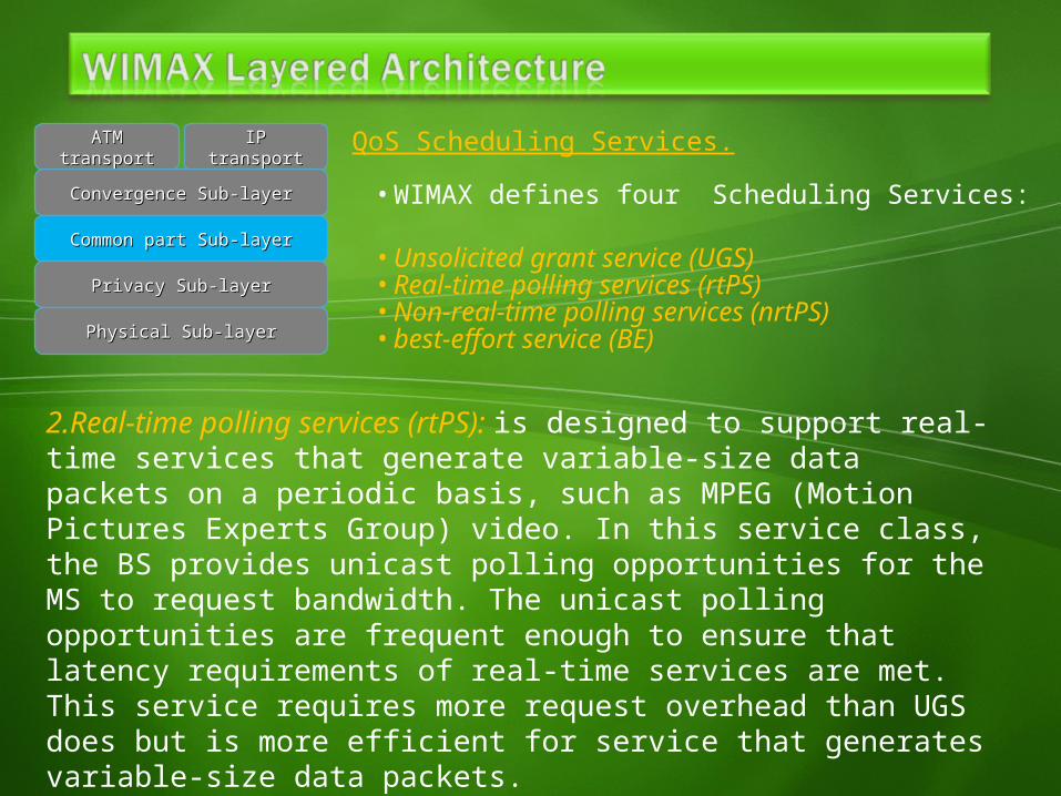
2.Real-time polling services (rtPS): is designed to support real-time services that generate variable-size data packets on a periodic basis, such as MPEG (Motion Pictures Experts Group) video. In this service class, the BS provides unicast polling opportunities for the MS to request bandwidth. The unicast polling opportunities are frequent enough to ensure that latency requirements of real-time services are met. This service requires more request overhead than UGS does but is more efficient for service that generates variable-size data packets.
• WIMAX defines four Scheduling Services:• Unsolicited grant service (UGS)• Real-time polling services (rtPS)• Non-real-time polling services (nrtPS)• best-effort service (BE)
QoS Scheduling Services.ATMATMtransporttransport
IPIPtransporttransport
Convergence Sub-layerConvergence Sub-layer
Common part Sub-layerCommon part Sub-layer
Privacy Sub-layerPrivacy Sub-layer
Physical Sub-layerPhysical Sub-layer
3.non-real-time polling services (nrtPS): is very similar to rtPS except that the MS can also use contention-based polling in the uplink to request bandwidth. In nrtPS, it is allowable to have unicast polling opportunities, but the average duration between two such opportunities is in the order of few seconds, which is large compared to rtPS. All the MSs belonging to the group can also request resources during the contention-based polling opportunity, which can often result in collisions and additional attempts.
• WIMAX defines four Scheduling Services:• Unsolicited grant service (UGS)• Real-time polling services (rtPS)• Non-real-time polling services (nrtPS)• best-effort service (BE)
QoS Scheduling Services.ATMATMtransporttransport
IPIPtransporttransport
Convergence Sub-layerConvergence Sub-layer
Common part Sub-layerCommon part Sub-layer
Privacy Sub-layerPrivacy Sub-layer
Physical Sub-layerPhysical Sub-layer
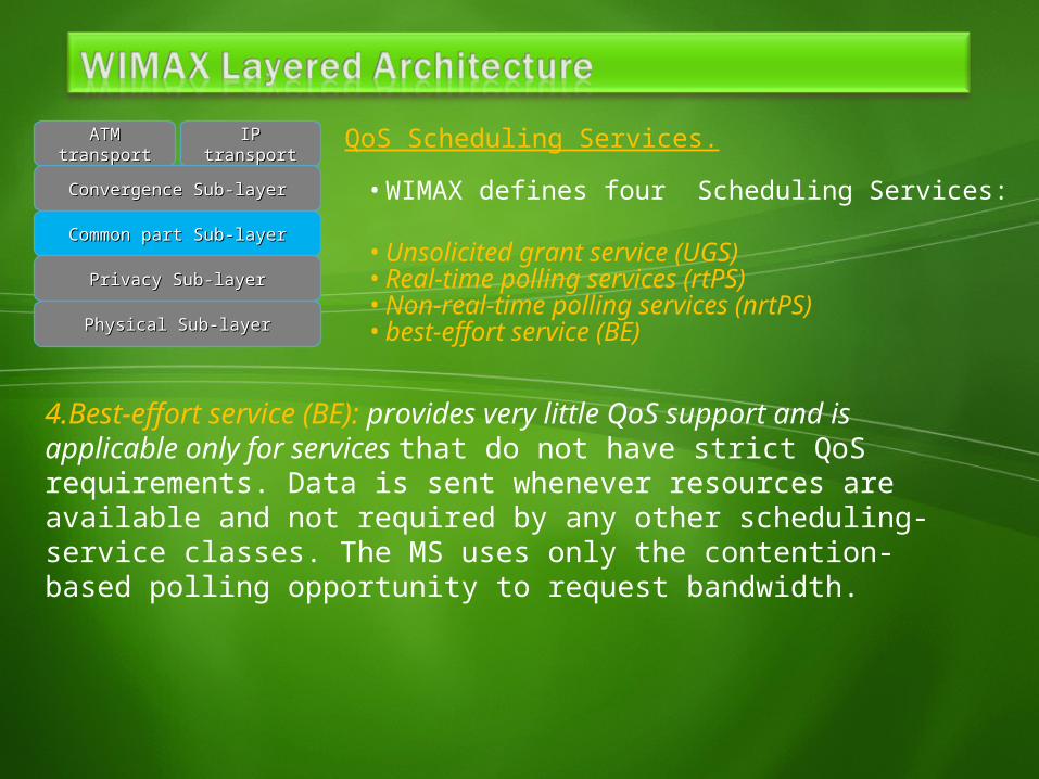
4.Best-effort service (BE): provides very little QoS support and is applicable only for services that do not have strict QoS requirements. Data is sent whenever resources are available and not required by any other scheduling-service classes. The MS uses only the contention-based polling opportunity to request bandwidth.
• WIMAX defines four Scheduling Services:• Unsolicited grant service (UGS)• Real-time polling services (rtPS)• Non-real-time polling services (nrtPS)• best-effort service (BE)
QoS Service Flow.ATMATMtransporttransport
IPIPtransporttransport
Convergence Sub-layerConvergence Sub-layer
Common part Sub-layerCommon part Sub-layer
Privacy Sub-layerPrivacy Sub-layer
Physical Sub-layerPhysical Sub-layer
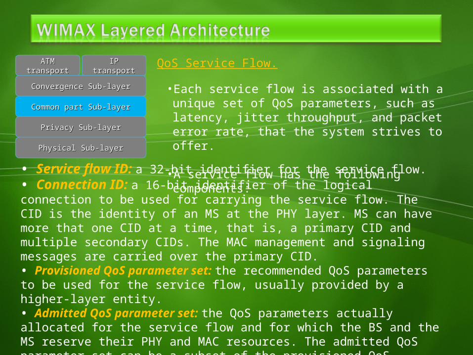
• Service flow ID: a 32-bit identifier for the service flow.• Connection ID: a 16-bit identifier of the logical connection to be used for carrying the service flow. The CID is the identity of an MS at the PHY layer. MS can have more that one CID at a time, that is, a primary CID and multiple secondary CIDs. The MAC management and signaling messages are carried over the primary CID.• Provisioned QoS parameter set: the recommended QoS parameters to be used for the service flow, usually provided by a higher-layer entity.• Admitted QoS parameter set: the QoS parameters actually allocated for the service flow and for which the BS and the MS reserve their PHY and MAC resources. The admitted QoS parameter set can be a subset of the provisioned QoS parameter set when the BS is not able, for a variety of reasons, to admit the service with the provisioned QoS parameter set.
• Each service flow is associated with a unique set of QoS parameters, such as latency, jitter throughput, and packet error rate, that the system strives to offer.
• A service flow has the following components:
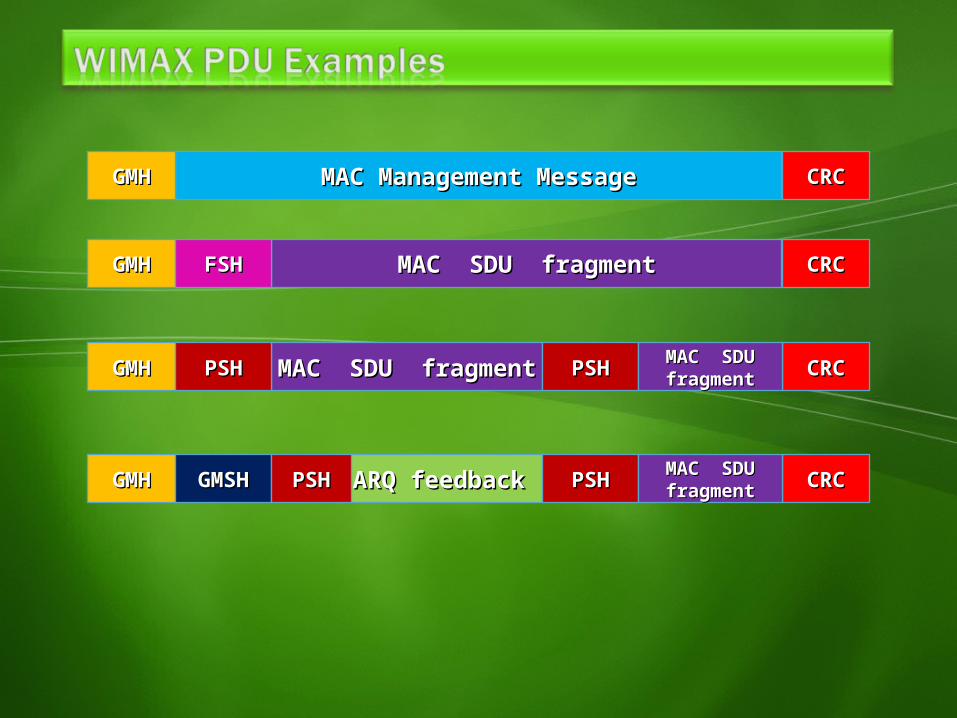
MAC Management MessageMAC Management MessageGMHGMH CRCCRC
MAC SDU fragmentMAC SDU fragmentGMHGMH CRCCRCFSHFSH
MAC SDU fragmentMAC SDU fragmentGMHGMH CRCCRCPSHPSH PSHPSH MAC SDUMAC SDUfragmentfragment
ARQ feedbackARQ feedbackGMHGMH CRCCRCGMSHGMSH PSHPSH MAC SDUMAC SDUfragmentfragmentPSHPSH
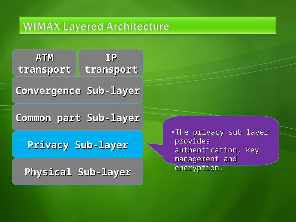
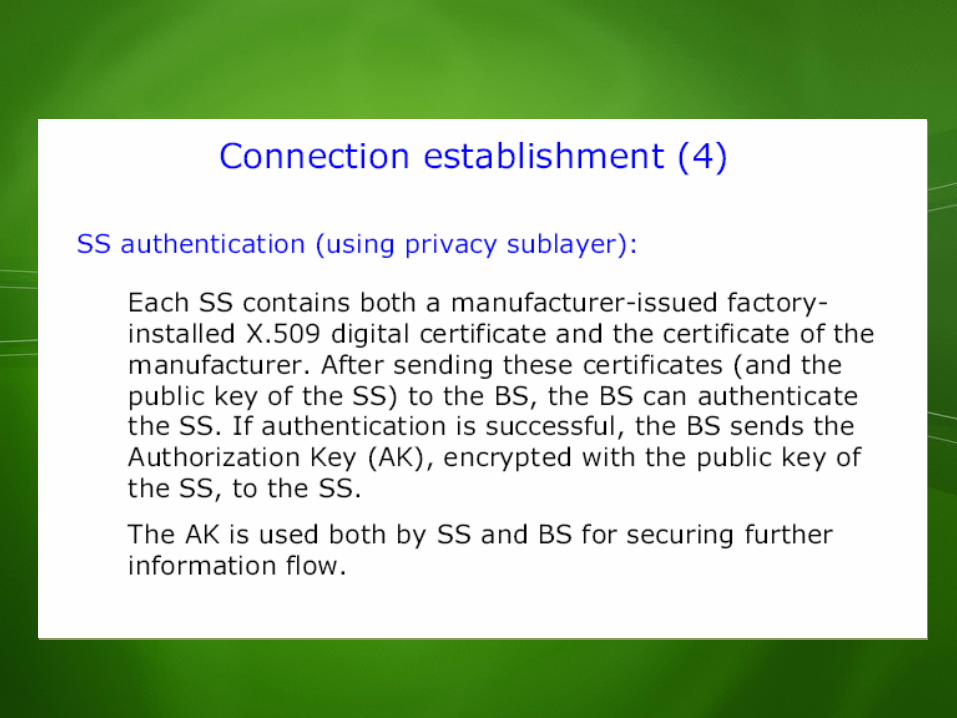
• The privacy sub layer The privacy sub layer provides authentication, provides authentication, key management and key management and encryption.encryption.
ATMATMtransporttransport
IPIPtransporttransport
Convergence Sub-layerConvergence Sub-layer
Common part Sub-layerCommon part Sub-layer
Privacy Sub-layerPrivacy Sub-layer
Physical Sub-layerPhysical Sub-layer
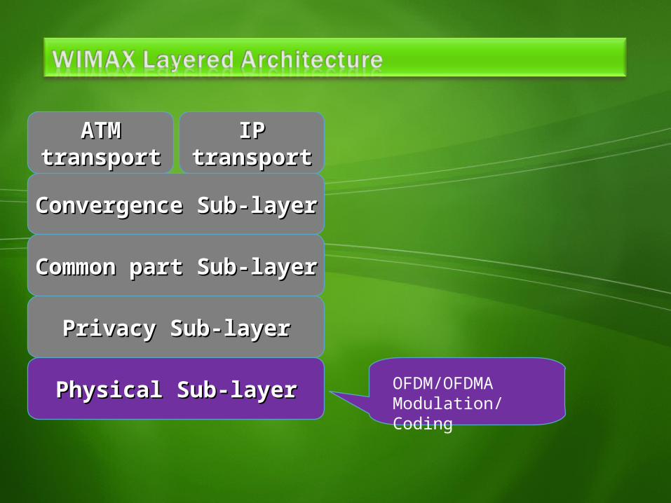
OFDM/OFDMAModulation/Coding
ATMATMtransporttransport
IPIPtransporttransport
Convergence Sub-layerConvergence Sub-layer
Common part Sub-layerCommon part Sub-layer
Privacy Sub-layerPrivacy Sub-layer
Physical Sub-layerPhysical Sub-layer
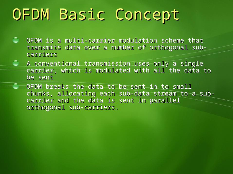
OFDM Basic ConceptOFDM Basic ConceptOFDM is a multi-carrier modulation scheme that transmits OFDM is a multi-carrier modulation scheme that transmits data over a number of orthogonal sub-carriers data over a number of orthogonal sub-carriers A conventional transmission uses only a single carrier, A conventional transmission uses only a single carrier, which is modulated with all the data to be sentwhich is modulated with all the data to be sentOFDM breaks the data to be sent in to small chunks, OFDM breaks the data to be sent in to small chunks, allocating each sub-data stream to a sub-carrier and the allocating each sub-data stream to a sub-carrier and the data is sent in parallel orthogonal sub-carriers.data is sent in parallel orthogonal sub-carriers.

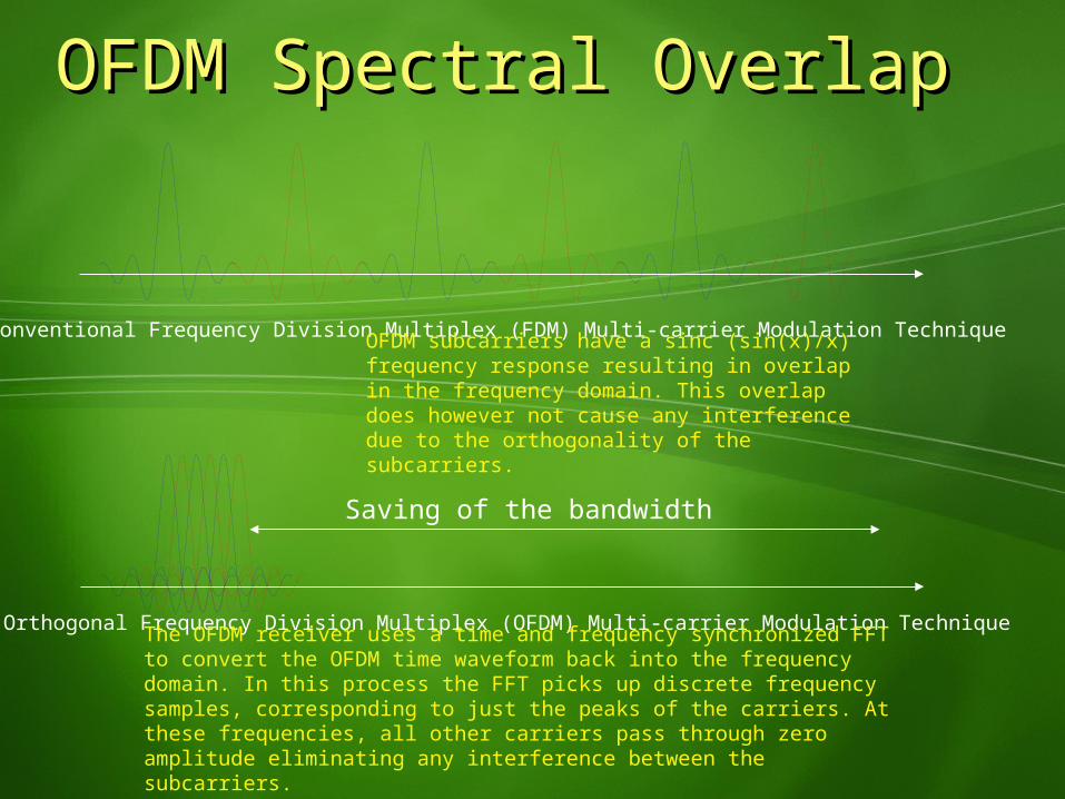
OFDM Spectral OverlapOFDM Spectral Overlap
Conventional Frequency Division Multiplex (FDM) Multi-carrier Modulation Technique
Saving of the bandwidth
Orthogonal Frequency Division Multiplex (OFDM) Multi-carrier Modulation Technique
OFDM subcarriers have a sinc (sin(x)/x) frequency response resulting in overlap in the frequency domain. This overlap does however not cause any interference due to the orthogonality of the subcarriers.
The OFDM receiver uses a time and frequency synchronized FFT to convert the OFDM time waveform back into the frequency domain. In this process the FFT picks up discrete frequency samples, corresponding to just the peaks of the carriers. At these frequencies, all other carriers pass through zero amplitude eliminating any interference between the subcarriers.

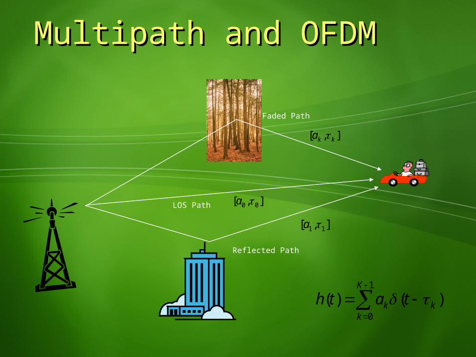
Multipath and OFDMMultipath and OFDM
1
0
()()K
kkk tath
],[ 00 a
],[ 11 a
Faded Path
Reflected Path
LOS Path
],[ kka
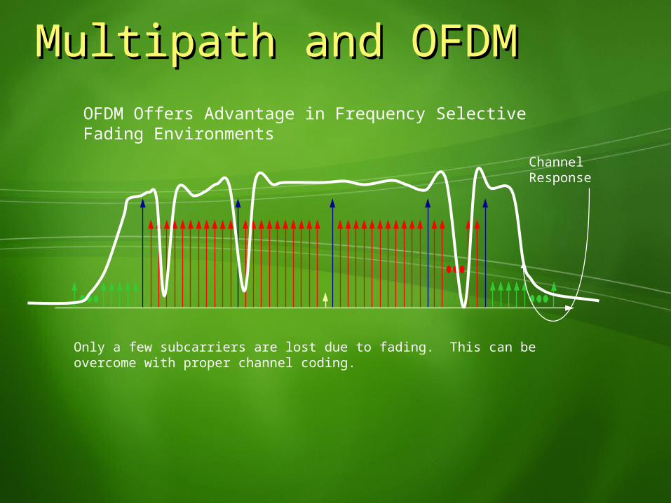
Multipath and OFDMMultipath and OFDMOFDM Offers Advantage in Frequency Selective Fading Environments
Channel Response
Only a few subcarriers are lost due to fading. This can be overcome with proper channel coding.
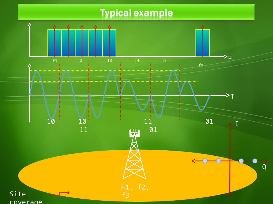
Site coverage
FF1 f2 f3 f4 f5 fn
F1, f2, f3
I
Q
T
10 10 11 01 11 01
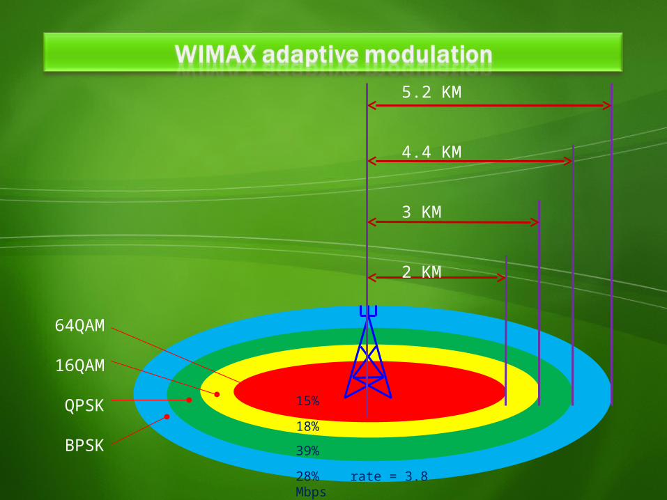
64QAM
16QAM
QPSK
BPSK
5.2 KM
4.4 KM
3 KM
2 KM
15%18%39%28% rate = 3.8 Mbps
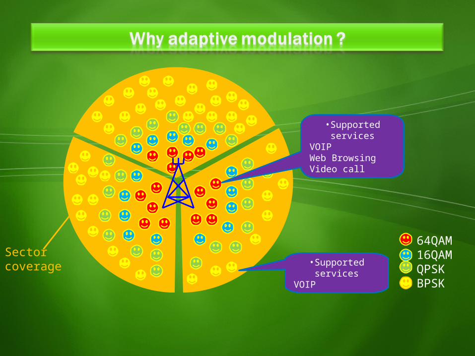
•Supported services
VOIP
•Supported services
VOIPWeb BrowsingVideo call
Sector coverage
64QAM16QAMQPSKBPSK
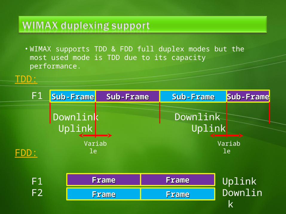
• WIMAX supports TDD & FDD full duplex modes but the most used mode is TDD due to its capacity performance.
FrameFrame FrameFrameFrameFrame FrameFrame
FDD:
F1F2
UplinkDownlink
TDD:Sub-FrameSub-Frame Sub-FrameSub-FrameF1
Downlink Uplink
Sub-FrameSub-Frame Sub-FrameSub-Frame
Downlink Uplink
Variable
Variable
FrameFrame
Sub-FrameSub-Frame Sub-FrameSub-Frame
Downlink Uplink
Variable
FrameFrame FrameFrame……...
…
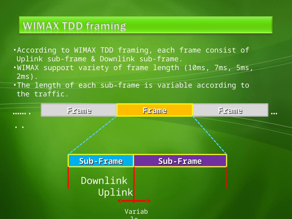
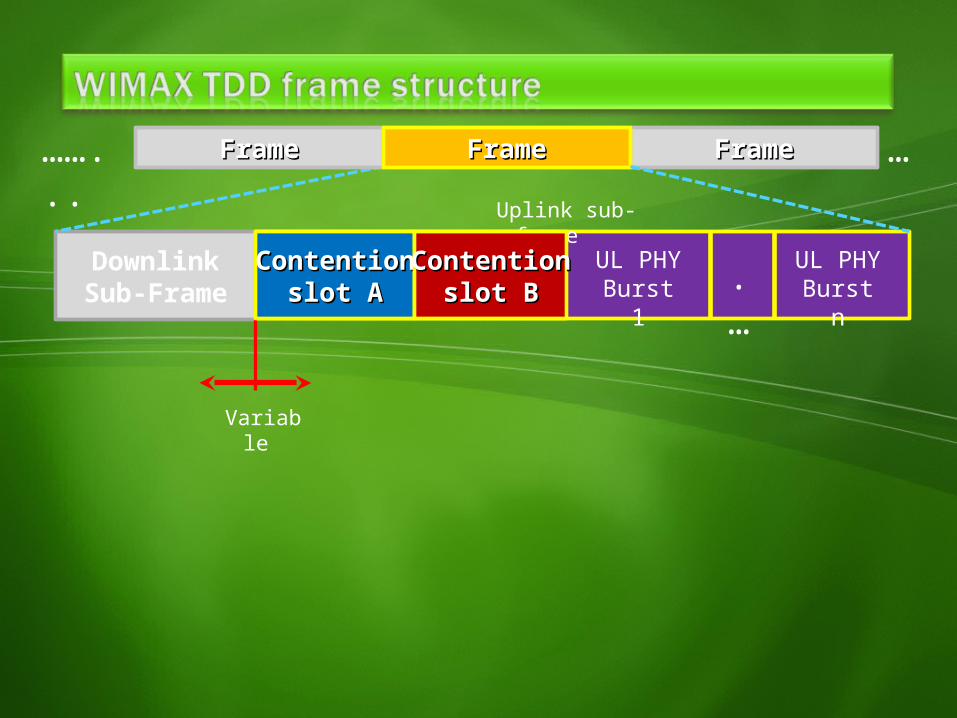
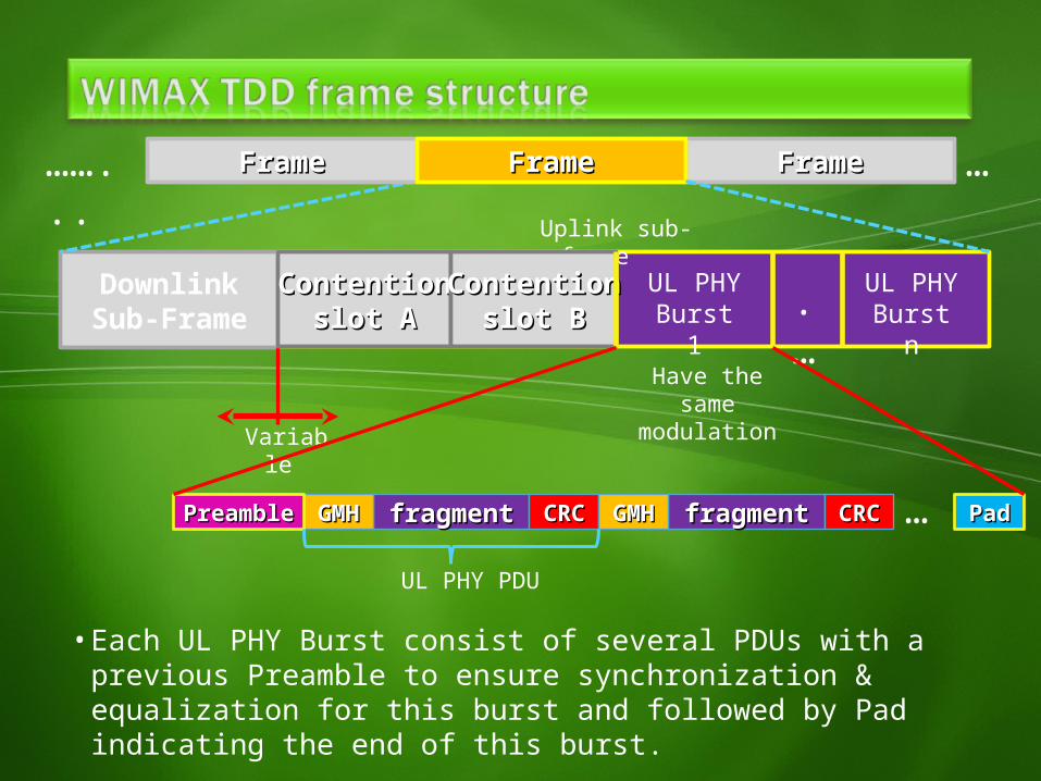
• According to WIMAX TDD framing, each frame consist of Uplink sub-frame & Downlink sub-frame.
• WIMAX support variety of frame length (10ms, 7ms, 5ms, 2ms).• The length of each sub-frame is variable according to the traffic.
FrameFrame
DownlinkSub-Frame
Uplink sub-frame
Variable
FrameFrame FrameFrame……...
…
ContentionContentionslot Aslot A
ContentionContentionslot Bslot B .
…UL PHYBurst 1
UL PHYBurst n
FrameFrame
DownlinkSub-Frame
Uplink sub-frame
Variable
FrameFrame FrameFrame……...
…
ContentionContentionslot Bslot B .
…UL PHYBurst 1
UL PHYBurst n
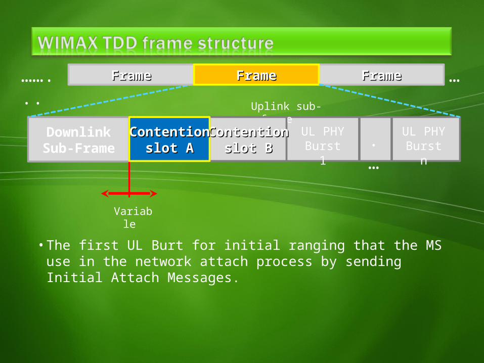
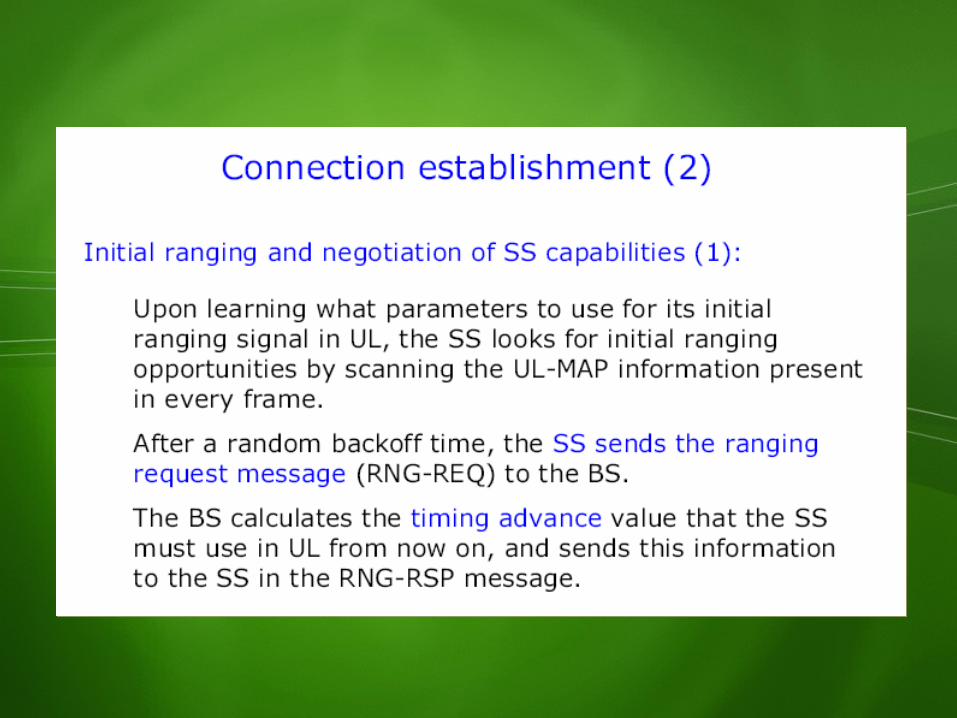
• The first UL Burt for initial ranging that the MS use in the network attach process by sending Initial Attach Messages.
ContentionContentionslot Aslot A
FrameFrame
DownlinkSub-Frame
Uplink sub-frame
Variable
FrameFrame FrameFrame……...
…
.…
UL PHYBurst 1
UL PHYBurst n
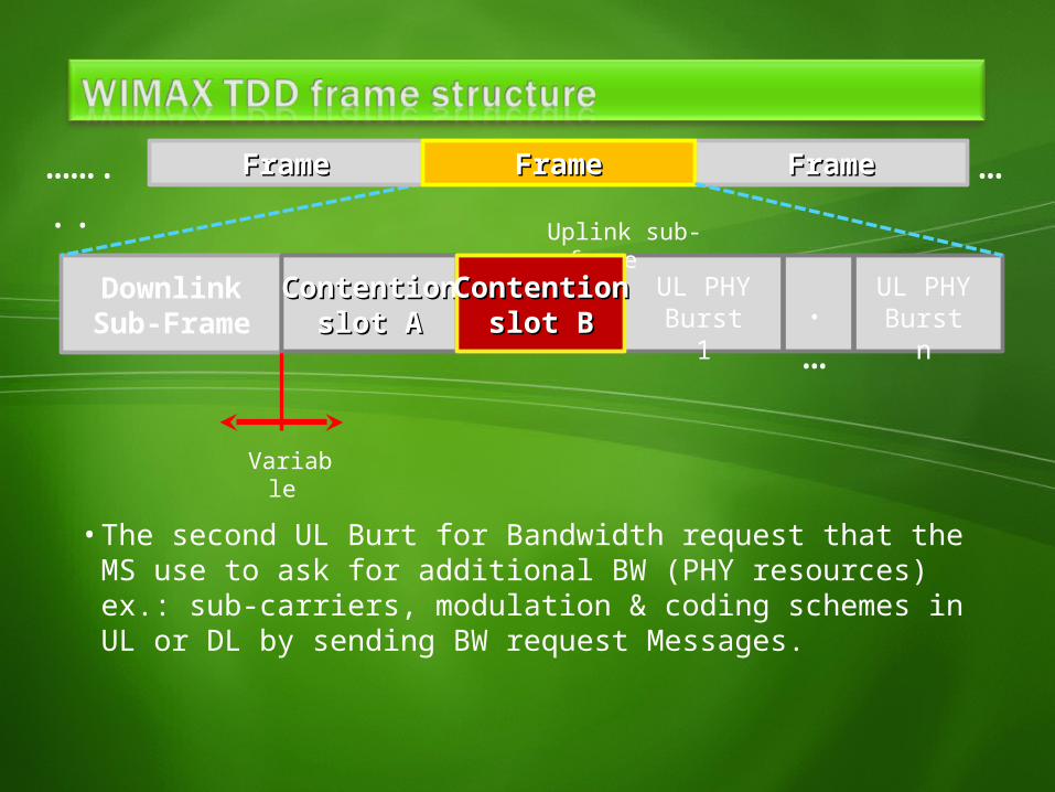
• The second UL Burt for Bandwidth request that the MS use to ask for additional BW (PHY resources) ex.: sub-carriers, modulation & coding schemes in UL or DL by sending BW request Messages.
ContentionContentionslot Aslot A
ContentionContentionslot Bslot B
FrameFrame
DownlinkSub-Frame
Uplink sub-frame
Variable
FrameFrame FrameFrame……...
…
.…
UL PHYBurst 1
UL PHYBurst n
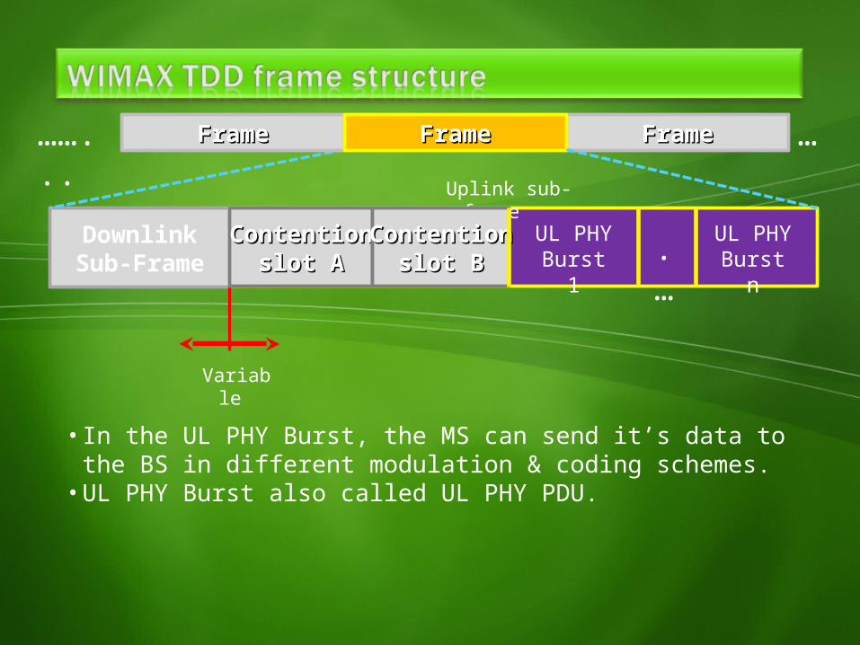
• In the UL PHY Burst, the MS can send it’s data to the BS in different modulation & coding schemes.
• UL PHY Burst also called UL PHY PDU.
ContentionContentionslot Aslot A
ContentionContentionslot Bslot B
FrameFrame
DownlinkSub-Frame
Uplink sub-frame
Variable
FrameFrame FrameFrame……...
…
.…
UL PHYBurst 1
UL PHYBurst n
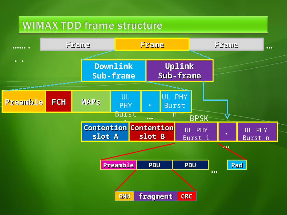
• Each UL PHY Burst consist of several PDUs with a previous Preamble to ensure synchronization & equalization for this burst and followed by Pad indicating the end of this burst.
ContentionContentionslot Aslot A
ContentionContentionslot Bslot B
fragmentfragmentGMHGMH CRCCRC fragmentfragmentGMHGMH CRCCRC PadPadPreamblePreamble …UL PHY PDU
Have the same modulation
UplinkUplinkSub-frameSub-frame
FrameFrameFrameFrame FrameFrame……...
…
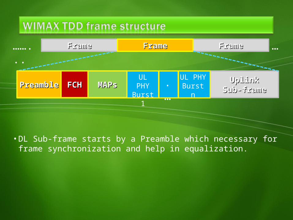
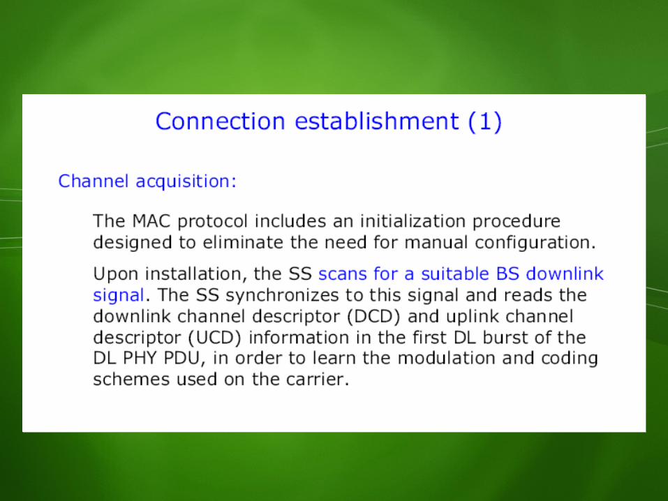
• DL Sub-frame starts by a Preamble which necessary for frame synchronization and help in equalization.
PreamblePreamble FCHFCH MAPsMAPs .…
UL PHY
Burst 1
UL PHYBurst n
UplinkUplinkSub-frameSub-frame
FrameFrameFrameFrame FrameFrame……...
…
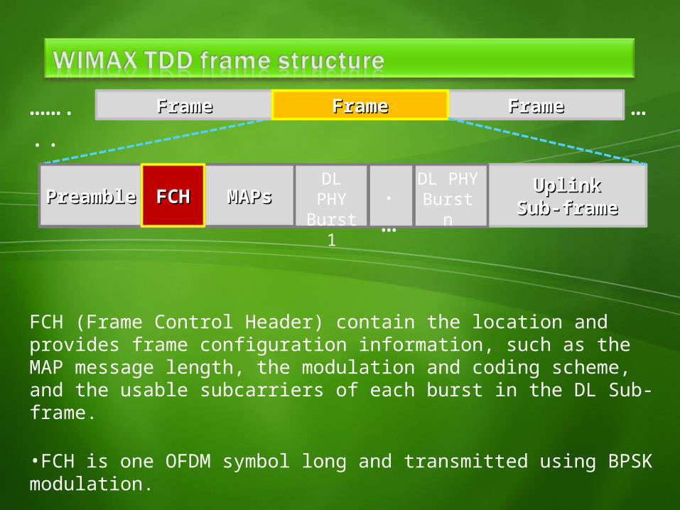
FCH (Frame Control Header) contain the location and provides frame configuration information, such as the MAP message length, the modulation and coding scheme, and the usable subcarriers of each burst in the DL Sub-frame.
•FCH is one OFDM symbol long and transmitted using BPSK modulation.
PreamblePreamble MAPsMAPs .…
DL PHY
Burst 1
DL PHYBurst nFCHFCH
UplinkUplinkSub-frameSub-frame
FrameFrameFrameFrame FrameFrame……...
…
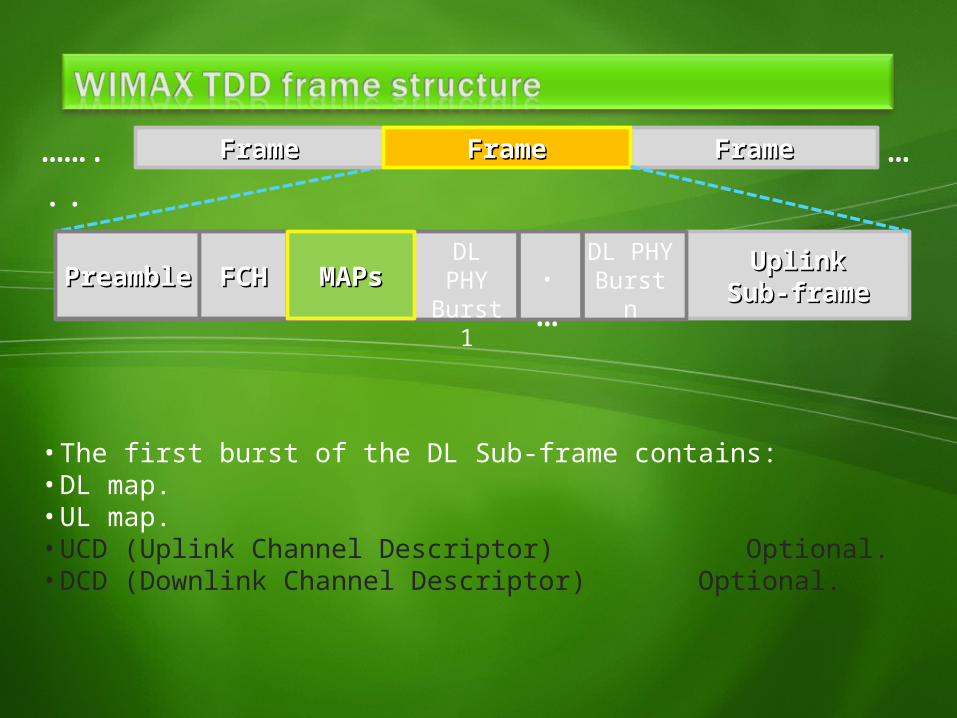
• The first burst of the DL Sub-frame contains:• DL map.• UL map.• UCD (Uplink Channel Descriptor) Optional.• DCD (Downlink Channel Descriptor) Optional.
PreamblePreamble .…
DL PHY
Burst 1
DL PHYBurst nFCHFCH MAPsMAPs
UplinkUplinkSub-frameSub-frame
FrameFrameFrameFrame FrameFrame……...
…
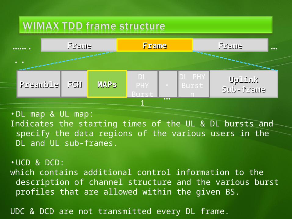
• DL map & UL map:Indicates the starting times of the UL & DL bursts and specify the
data regions of the various users in the DL and UL sub-frames.
• UCD & DCD:which contains additional control information to the description of
channel structure and the various burst profiles that are allowed within the given BS.
UDC & DCD are not transmitted every DL frame.
PreamblePreamble .…
DL PHY
Burst 1
DL PHYBurst nFCHFCH MAPsMAPs
UplinkUplinkSub-frameSub-frame
FrameFrameFrameFrame FrameFrame……...
…
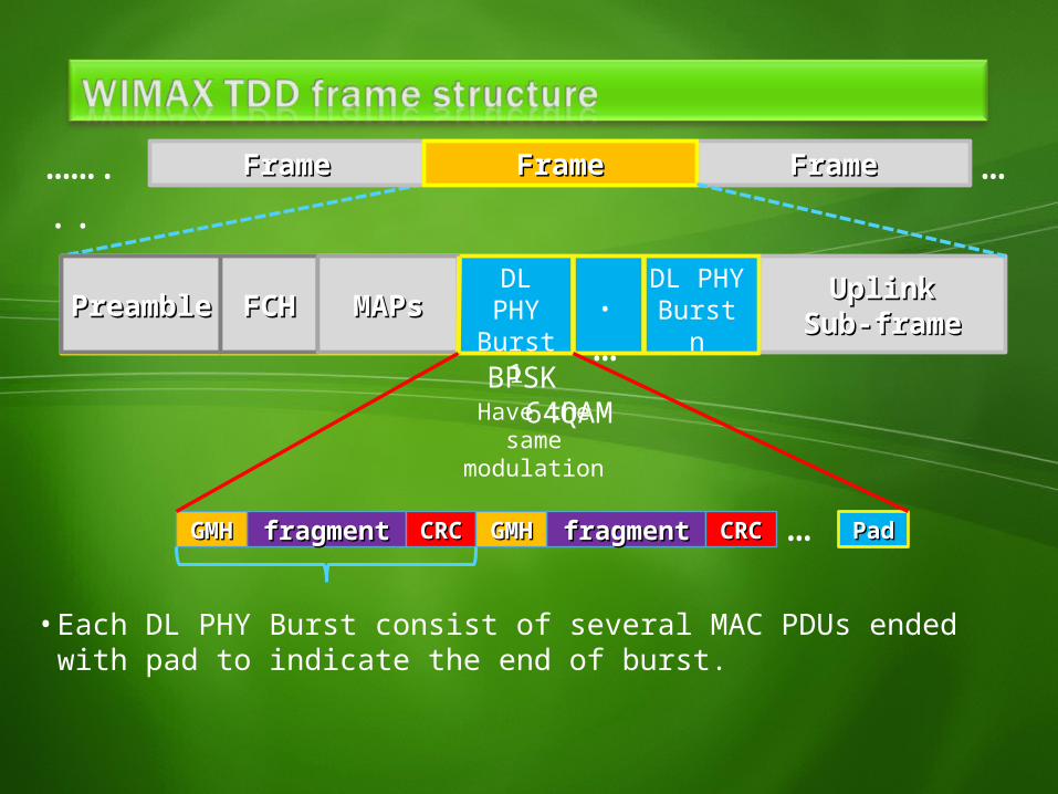
• Each DL PHY Burst consist of several MAC PDUs ended with pad to indicate the end of burst.
PreamblePreamble .…
DL PHY
Burst 1
DL PHYBurst nFCHFCH MAPsMAPs
BPSK 64QAM
fragmentfragmentGMHGMH CRCCRC fragmentfragmentGMHGMH CRCCRC PadPad…
Have the same modulation
FrameFrameFrameFrame FrameFrame……...
…
BPSK 64QAM
UplinkUplinkSub-frameSub-frame
DownlinkSub-frame
PreamblePreamble FCHFCH MAPsMAPs .…
UL PHY
Burst 1
UL PHYBurst n
ContentionContentionslot Aslot A
ContentionContentionslot Bslot B .
…UL PHYBurst 1
UL PHYBurst n
fragmentfragmentGMHGMH CRCCRC
PadPadPreamblePreamble …PDUPDU PDUPDU
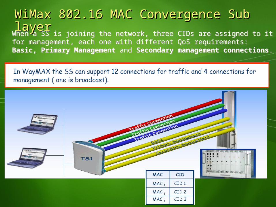
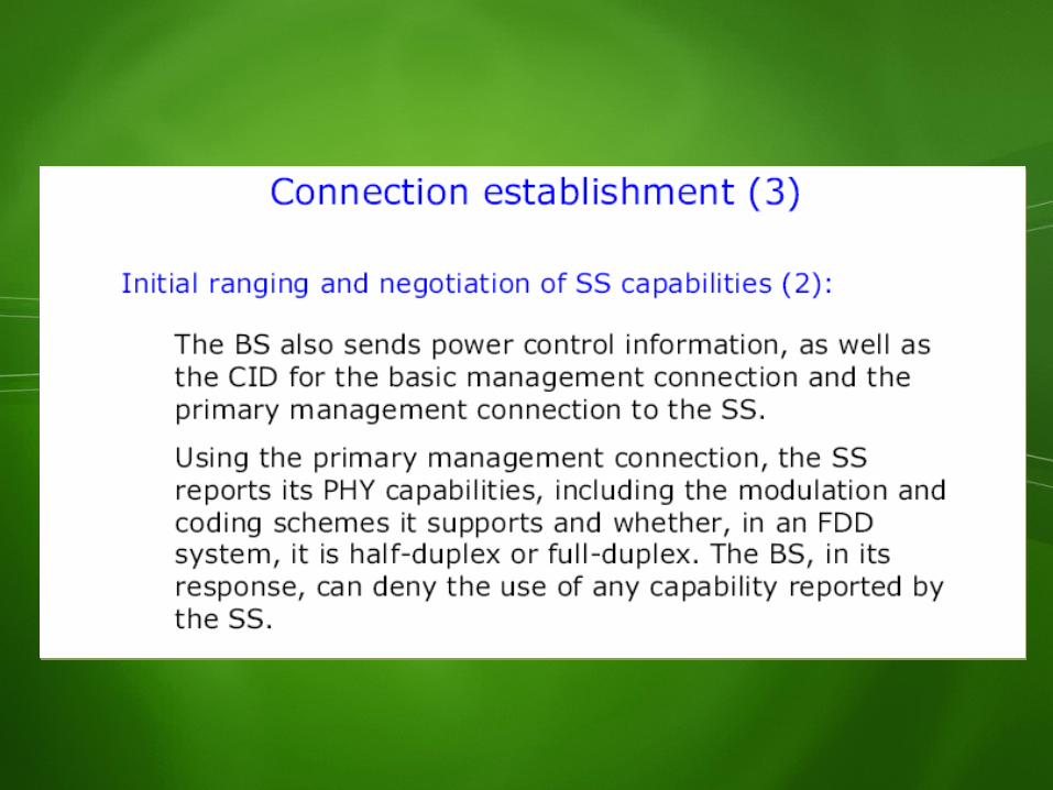
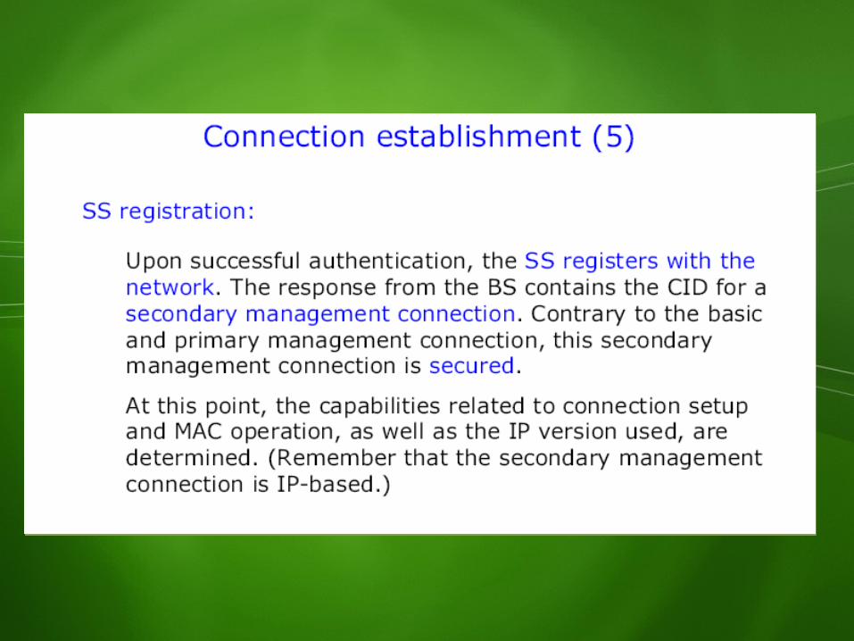
When a SS is joining the network, three CIDs are assigned to it for management, each one with different QoS requirements: Basic, Primary Management and Secondary management connections.
WiMax 802.16 MAC Convergence Sub WiMax 802.16 MAC Convergence Sub layerlayer
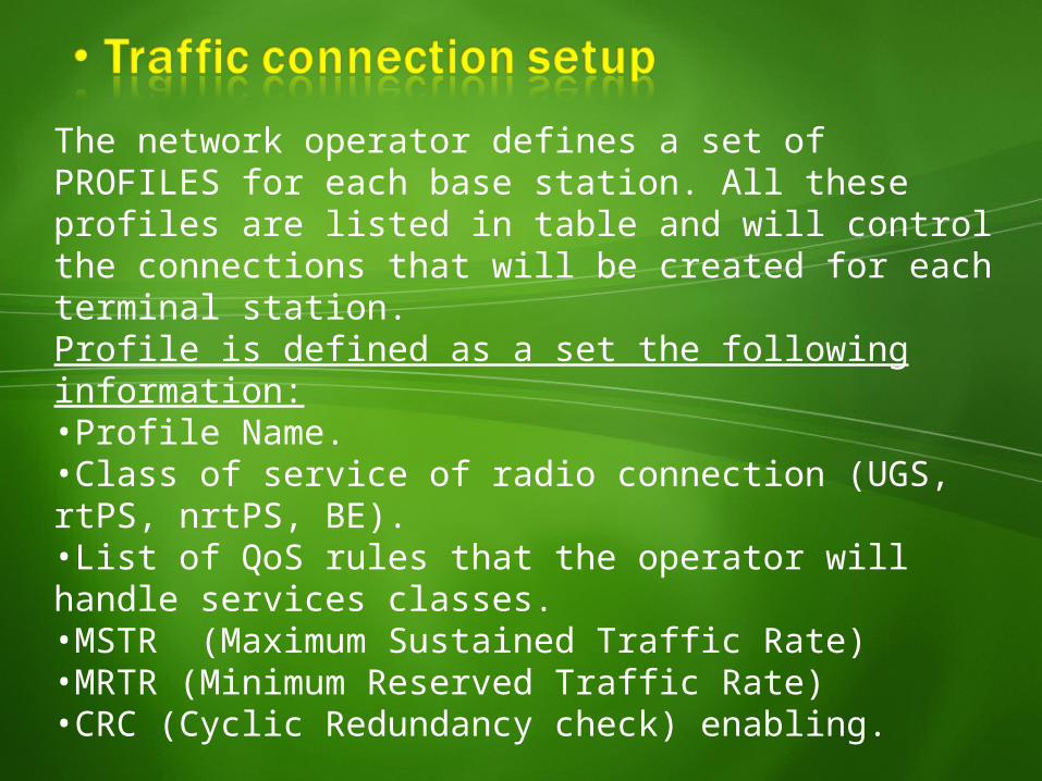
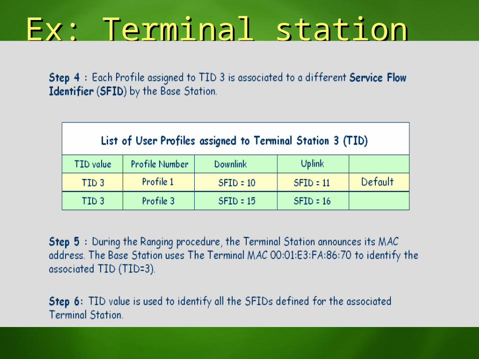
The network operator defines a set of PROFILES for each base station. All these profiles are listed in table and will control the connections that will be created for each terminal station.
Profile is defined as a set the following information:•Profile Name.•Class of service of radio connection (UGS, rtPS, nrtPS, BE).•List of QoS rules that the operator will handle services classes.•MSTR (Maximum Sustained Traffic Rate)•MRTR (Minimum Reserved Traffic Rate)•CRC (Cyclic Redundancy check) enabling.
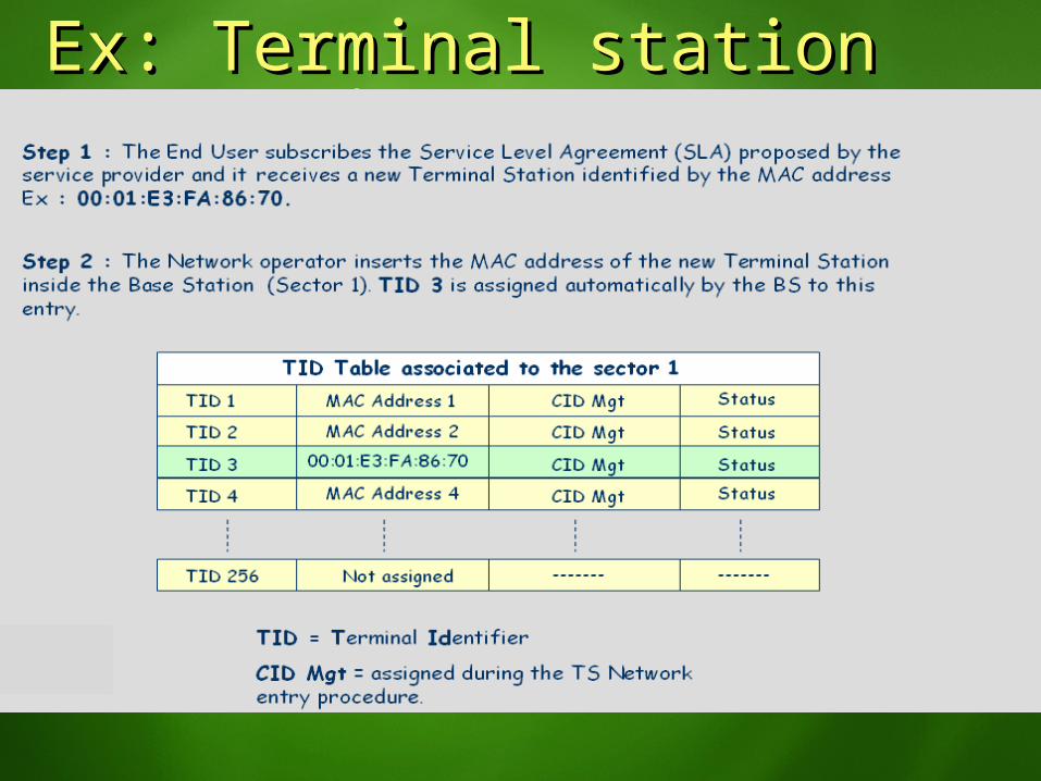
Ex: Terminal station Ex: Terminal station connection setup (1) connection setup (1)
Ex: Terminal station Ex: Terminal station connection setup (2) connection setup (2)
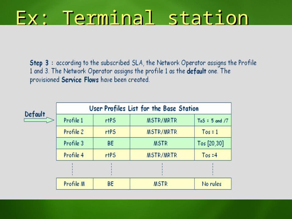
Ex: Terminal station Ex: Terminal station connection setup (3) connection setup (3)
Ex: Terminal station Ex: Terminal station connection setup (4)connection setup (4)
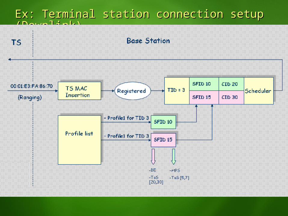
Ex: Terminal station connection setup Ex: Terminal station connection setup (Downlink)(Downlink)

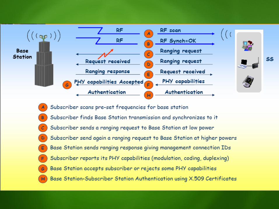
Network EntryNetwork Entry
OFDMOFDMPhysical LayerPhysical Layer

OFDM Basic ConceptOFDM Basic ConceptOFDM is a multi-carrier modulation scheme that transmits OFDM is a multi-carrier modulation scheme that transmits data over a number of orthogonal sub-carriers data over a number of orthogonal sub-carriers A conventional transmission uses only a single carrier, A conventional transmission uses only a single carrier, which is modulated with all the data to be sentwhich is modulated with all the data to be sentOFDM breaks the data to be sent in to small chunks, OFDM breaks the data to be sent in to small chunks, allocating each sub-data stream to a sub-carrier and the allocating each sub-data stream to a sub-carrier and the data is sent in parallel orthogonal sub-carriers.data is sent in parallel orthogonal sub-carriers.
OFDM Spectral OverlapOFDM Spectral Overlap
Conventional Frequency Division Multiplex (FDM) Multi-carrier Modulation Technique
Saving of the bandwidth
Orthogonal Frequency Division Multiplex (OFDM) Multi-carrier Modulation Technique
OFDM subcarriers have a sinc (sin(x)/x) frequency response resulting in overlap in the frequency domain. This overlap does however not cause any interference due to the orthogonality of the subcarriers.
The OFDM receiver uses a time and frequency synchronized FFT to convert the OFDM time waveform back into the frequency domain. In this process the FFT picks up discrete frequency samples, corresponding to just the peaks of the carriers. At these frequencies, all other carriers pass through zero amplitude eliminating any interference between the subcarriers.
Multipath and OFDMMultipath and OFDM
1
0
()()K
kkk tath
],[ 00 a
],[ 11 a
Faded Path
Reflected Path
LOS Path
],[ kka

Multipath and OFDMMultipath and OFDMOFDM Offers Advantage in Frequency Selective Fading Environments
Channel Response
Only a few subcarriers are lost due to fading. This can be overcome with proper channel coding.
……
……
……
……
……
……
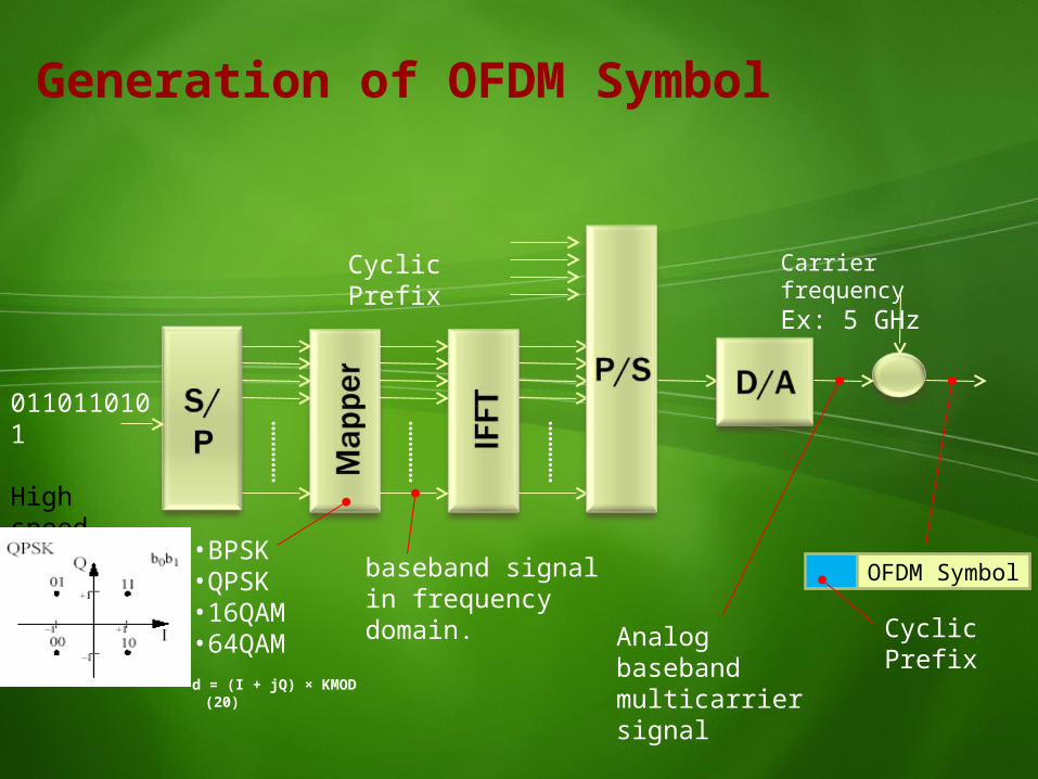
OFDM Symbol
0110110101
High speed data
Cyclic Prefix
• BPSK• QPSK• 16QAM• 64QAMd = (I + jQ) × KMOD
(20)
Cyclic Prefix
Carrier frequencyEx: 5 GHz
Analog baseband multicarrier signal
Generation of OFDM Symbol
baseband signal in frequency domain.
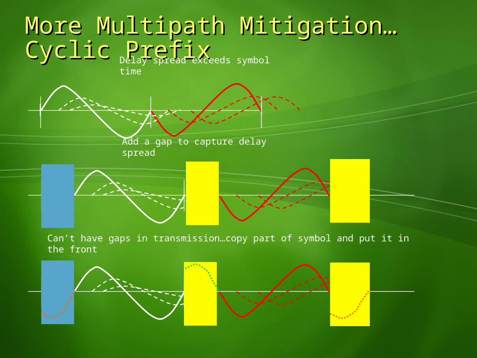
More Multipath Mitigation…Cyclic More Multipath Mitigation…Cyclic PrefixPrefix Delay spread exceeds symbol
time
Add a gap to capture delay spread
Can’t have gaps in transmission…copy part of symbol and put it in the front


![IEEE 802.16: WiMAX Overview, WiMAX · PDF filevs. 3G. The common Misconceptions about WiMAX & 3G CDMA are [5]: 1) Cost . c. ... IEEE 802.16: WiMAX Overview, WiMAX Architecture . Mojtaba](https://img.pdfslide.us/doc/110x75/5a752f217f8b9ad22a8c6f07/ieee-80216-wimax-overview-wimax-architecture-vs-3g-the-common-misconceptions.jpg)