Embed Size (px)
Citation preview

2
Wilson Audio® is a registered trademark of Wilson Audio Specialties, Inc.
Cub®, WATT/Puppy®, MAXX®, Alexandria®, and X-1/Grand SLAMM® are registered trade-marks of Wilson Audio Specialties, Inc.
WATCH Center™, WATCH Surround™, and WATCH Dog™ are trademarks of Wilson AudioSpecialties, Inc.
This manual was produced by the Wilson Audio Engineering Department in cooperation withSales and Marketing. The information contained herein is subject to change without notice. CurrentRevision 2.0. If you are in need of a more recent manual, please contact your dealer.
The information in this manual is the sole property of Wilson Audio Specialties, Inc. Any repro-duction, in whole or in part, without the express written permission of Wilson Audio Specialties, Inc., isprohibited. No material contained herein may be transmitted in any form or by any means, electronic or
mechanical, for any purpose, without the express written permission of Wilson Audio Specialties, Inc.
3
Ta b l e O f C o n t e n t s
Section 1.0 - WATCH Dog Introduction .............................. 9Design Considerations ...................................................... 9Applications ....................................................................10Enclosure Materials Technology ........................................10Adhesives ......................................................................11Depth of Design ..............................................................11
Section 1.1 - WATCH Package ........................................ 11WATCH Center ................................................................11WATCH Surround ............................................................12Conclusion ......................................................................13
Section 2.0 - Room Reflections ........................................17Slap-Echo ......................................................................17Standing Waves ..............................................................18Comb Filter Effect ............................................................19
Section 3.0 - Resonance ................................................ 21Structural Resonance...................................................... 21Air Volume Resonance .................................................... 21
Section 4.0 - Initial Setup................................................ 27System Setup .............................................................. 27Zone of Neutrality .......................................................... 27
Section 4.1 - Choosing a Listening Position ......................30Home Theater ................................................................30Speaker Placement vs. Listening Position - Main Speakers 30Center Channel ..............................................................31Speaker Orientation ........................................................32Surround Channel ............................................................32WATCH Dog Subwoofer ..................................................32

4
Section 4.2 - WATCH Dog Setup in a Music System ..........33
Section 4.3 - Initial Setup Summary..................................34
Section 5.0 - WATCH Dog Setup .................................... 39Preparation .................................................................... 39Uncrating the WATCH Dog ............................................ 39
Section 5.1 - Connecting the WATCH Dog - Home Theater 40
Connection with a Surround Processor ............................ 40
Section 5.2 - Connecting the Dog -Two-Channel System ..41Bypassing the High Pass Filter ...................................... 41 Utilizing the High Pass Filter ............................................ 42
Section 6.0 - Control Panel Setup and Final Tuning ..........49Preparation .................................................................... 49
Section 6.1 - Notes From David A. Wilson on Using the Test CD ..........................................................50
Subwoofer Placement ......................................................50Filtering of LF to the L & R Speakers ................................50Initial Placement of the L & R Speakers ............................51Introduction of the WATCH Dog into Your System ..............54To EQ or Not to EQ..........................................................57
Section 6.2 - Break-in Period ..........................................59
Section 7.0 - WATCH Dog Spikes ....................................63Assembly ........................................................................................63
Section 8.0 - WATCH Dog 12 Volt Triggers ........................67
Ta b l e o f C o n t e n t s - C o n t i n u e d

5
Section 9.0 - Care of the Finish ........................................73Care of Your WATCH Dog ................................................73
Section 10.0 - WATCH Dog Specifications ........................79
Section 11.0 - Warranty Information ................................79
Ta b l e o f C o n t e n t s - C o n t i n u e d


8
9
W a t c h D o g ® I n t r o d u c t i o n
Section 1.0 - WATCH Dog Introduction
The WATCH (Wilson Audio Theater Comes Home) Dog powered subwoofer isthe culmination of over twenty years of experience at Wilson Audio in building highoutput, ultra-low distortion woofer and subwoofer products. It was designed to furtherextend and enhance the bottom octave performance of music and theater systemswithout compromising speed, tonal accuracy or phase coherency. The WATCH Dogwill seamlessly and coherently integrate with any loudspeaker, whether you are aug-menting a two-channel system or as the LFE channel in a surround system.
Like other WATCH products, along with music system applications, the WATCHDog was designed to take advantage of today’s multi-channel formats. The uniquetune-ability of the WATCH Dog via its comprehensive control panel allows the WATCHDog to be optimized for both music and multi-channel applications, even within thesame system. The control panel’s adjustments allow critical setup, ensuring the bestpossible performance in a wide range of rooms and with a variety of speakers.
The fact is you haven’t truly experienced home theater until you’ve felt theimpact, power, and passion of a film score the way the director intended it, and nocompany will deliver this passion like Wilson Audio. That’s why, in the past decade, somany blockbuster hits have been mixed, composed, or recorded using Wilson Audioloudspeakers.
Design ConsiderationsYour WATCH Dog powered subwoofer has been designed to augment and
extend the bottom octave performance of Wilson Audio loudspeakers. This was a diffi-cult task because of the inherent speed, phase coherency, and dynamics typical ofWilson speakers. Wilson Audio loudspeakers have set the standard for performance ina wide variety of two-channel audio and multi-channel home theater applications. TheWATCH Dog powered subwoofer ensures the most seamless integration with yourWilson Audio loudspeakers. The WATCH Dog system is the only powered subdesigned specifically to match the inherent quality of the Sophia, WATT/Puppy, MAXX,

10
and, in many instances, the Alexandria X-2. To accomplish this task, David Wilson andhis engineering department used a state of the art subwoofer driver, sophisticatedelectronic crossovers, adjustable phase control, equalization controls, and amplifiersection, as well as sophisticated enclosure materials.
ApplicationsOne of Wilson Audio’s most important criteria in speaker development is that a
speaker meets the accuracy and dynamic demands of studio monitoring, analyticalhardware and software evaluation, and of course, critical music and theater sound-track listening. The WATCH Dog has been designed to deliver all of the speed, dynam-ics, and musical accuracy to satisfy even the most demanding music lovers.
The ultra long-throw, twelve inch driver is powered by a high current amplifierdesigned specifically for the WATCH Dog by Richard Marsh. A unique control centeradds the flexibility and tune-ability that truly redefines powered subwoofer perform-ance.
The WATCH Dog has been engineered to take full advantage of today’s multi-channel surround formats, including the latest AC-3 (Dolby Digital) and DTS (DigitalTheater Systems) formats.
It will provide years of satisfaction whether listening to two-channel audio,multi-channel audio, or to the latest movie sound track.
Enclosure MaterialsOnly the very best in materials are used in the WATCH Dog enclosure. The
enclosure of the WATCH Dog uses the same proprietary techniques that have beenvery successfully utilized in the Alexandria X-2, MAXX, Sophia, and the WATT/PUPPYsystems. The enclosure is made from a non-resonant composite material which isthen highly cross-braced to further reduce cabinet resonance. In the most criticalareas, the WATCH Dog uses our proprietary “X” material, a very dense, strong com-posite originally developed for the X-1 Grand SLAMM®.
11
AdhesivesThe engineers at Wilson have performed extensive research on the adhesives
used to construct our enclosures. Other speaker manufacturers often overlook thiscritical variable. Wilson has found that the adhesives used to construct enclosures arecrucial to the proper performance and longevity of a loudspeaker. Some of the impor-tant factors considered when selecting an adhesive are: correct modulus of elasticity,coefficient of thermal expansion, and natural frequency response.
A highly cross-linked, thermoset adhesive is used for the construction of theenclosure. It was also chosen for its excellent bond strength, solvent resistance, hard-ness, and optimum vibrational characteristics.
Depth of DesignThe combination of experience, engineering depth, and precision manufacturing
using the best in composite materials and adhesive technology, provided to us by theleaders in their industries, allows us to design enclosures with unmatched perform-ance. The WATCH system has been designed to eliminate vibration and cabinet signa-
ture while maintaining an internal acoustical integrity that is simply without equal.
Section 1.1 - WATCH Package
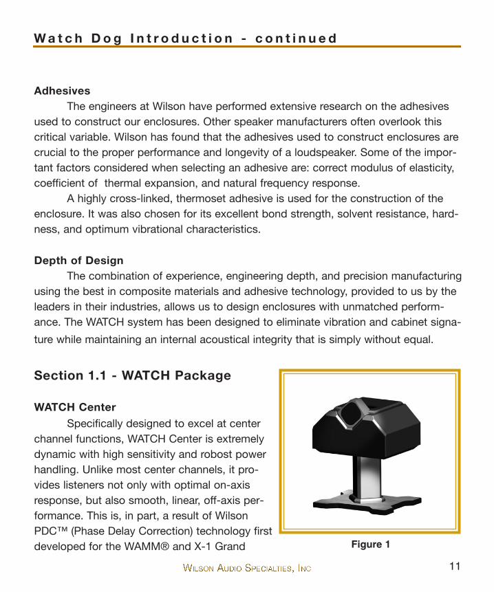
WATCH CenterSpecifically designed to excel at center
channel functions, WATCH Center is extremelydynamic with high sensitivity and robost powerhandling. Unlike most center channels, it pro-vides listeners not only with optimal on-axisresponse, but also smooth, linear, off-axis per-formance. This is, in part, a result of WilsonPDC™ (Phase Delay Correction) technology firstdeveloped for the WAMM® and X-1 Grand
W a t c h D o g I n t r o d u c t i o n - c o n t i n u e d
Figure 1
12
SLAMM systems and later applied to the rest of the Wilson Line. PDC allows for opti-mal tuning of a loudspeaker for various listening distances and heights and gives lis-teners much greater control over their sound.
The WATCH Center was designed from the ground up as a center channel. It isnot merely a standard speaker that was tipped onto its side. The center channel wasvoiced and optimized to truly represent dialogue for movies as well as music andvocals when used in a multi-channel audio setup.
Of course, WATCH Center lives up to Wilson’s high standards of cutting edgedesign, superior build quality, and stunning sonic performance. WATCH Center isshielded and is available with a matchingstand.
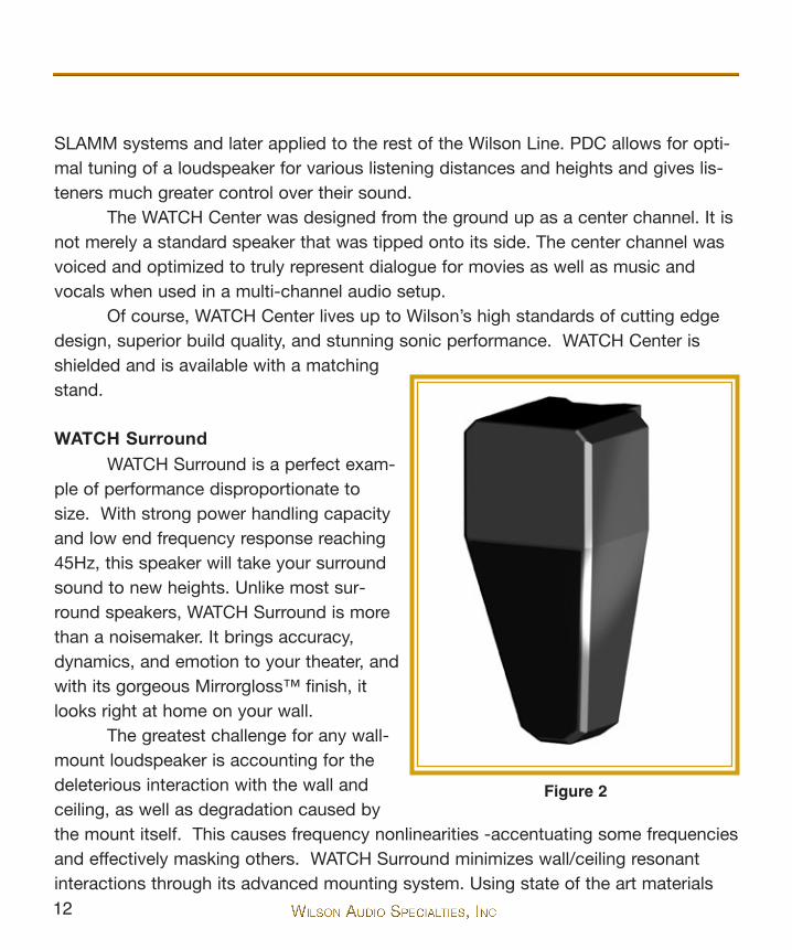
WATCH SurroundWATCH Surround is a perfect exam-
ple of performance disproportionate tosize. With strong power handling capacityand low end frequency response reaching45Hz, this speaker will take your surroundsound to new heights. Unlike most sur-round speakers, WATCH Surround is morethan a noisemaker. It brings accuracy,dynamics, and emotion to your theater, andwith its gorgeous Mirrorgloss™ finish, itlooks right at home on your wall.
The greatest challenge for any wall-mount loudspeaker is accounting for thedeleterious interaction with the wall andceiling, as well as degradation caused bythe mount itself. This causes frequency nonlinearities -accentuating some frequenciesand effectively masking others. WATCH Surround minimizes wall/ceiling resonantinteractions through its advanced mounting system. Using state of the art materials
Figure 2

13
technology first developed for the X-1 Grand SLAMM, WATCH Surround providesstunning results.
The Surround is mounted to its bracket by strategically located spikes, furtherreducing wall interaction and resonance. The Surround can also be rotated towardsthe listening position, offering improved integration with the front speakers and betterimaging.
CONCLUSION
Finally, a subwoofer designed and manufactured with the same commitment toexcellence that has characterized all products from Wilson Audio. The WATCH Dogcombines Olympian structural, design, and finish considerations with superior sonicquality. It is this approach that distinguishes Wilson Audio products. As a part of atruly high-end multi-channel system, or in a music system, the WATCH products offerunparalleled performance, quality of build, and longevity. Wilson Audio delivers a prod-uct that maintains the strictest structural tolerances, durability, and reliability. You willhave consistent, repeatable performance, unaffected by the climatic conditions, any-where in the world. The WATCH Dog, as well as the other WATCH products, will pro-vide an experience with film or music only obtainable through Wilson products.
W a t c h D o g I n t r o d u c t i o n - c o n t i n u e d


16

17
Note: The following section presents conceptual and practical informationon room acoustics. These concepts for two-channel audio become even moreimportant when dealing with multi-channel audio or home theater. The presenceof two or more speakers in a room only increases the amount of setup difficul-ties and speaker interactions. Careful study of the room acoustics principlesherein, followed by evaluating your own room configuration, will result in amarked improvement in the performance of your multi-channel system.
Section 2.0 - Room Reflections
There are three commonly encountered room reflection problems: slap-echo,standing waves, and comb filter effects.
Slap EchoProbably the most obnoxious form of reflection is called “slap echo.” In slap
echo, primarily mid-range and high frequency sounds reflect off of two parallel hardsurfaces. The sound literally reverberates back and forth until it is finally dissipatedover time. You can test for slap echo in any room by clapping your hands sharply inthe middle of the room and listening for the characteristic sound of the echo in themid-range. Slap echo destroys the sound quality of a stereo system primarily in twoways:
• Adding harshness to the upper mid-range and treble throughenergy time storage.
• Destroying the delicate phase relationships which help to establishsound stage and image localization cue.
Nonparallel walls do not support slap echo, but rather allow the sound to dif-fuse.
Slap echo is a common acoustical problem in typical domestic listening roomsbecause most of these rooms have walls of a hard, reflective nature, occasionally
I n Yo u r R o o m
18
interrupted by curtains or drapes. Slap echo can be controlled entirely by the applica-tion of absorptive materials to hard surfaces, such as:
• Sonex• Airduct board • Cork panels• Large ceiling to floor drapes• Carpeting to wall surfaces
In many domestic listening environments, heavy stuffed furnishings are the pri-mary structural control to slap echo. Unfortunately, their effectiveness is not pre-dictable. Diffusers are sometimes also used to very good subjective effect, particularlyin quite large rooms. Sound absorbent materials such as described above will alter thetonal characteristic of the room by making it sound “duller,” much heavier in the bass,less “bright and alive,” and “quieter.” These changes usually make the room morepleasant for conversation, but sometimes render it too dull in the high frequencies tobe musically involving. Diffusers, on the other hand, tend not to change the high fre-quency tonal balance characteristic of the room, but make the sound more “open.” Acombination of absorptive and diffusive treatments is usually the best approach.
Standing WavesAnother type of reflection phenomenon is standing waves. Standing waves
cause the unnatural boosting of certain frequencies, typically in the bass, at certaindiscreet locations in the room. A room generating severe standing waves will tend tomake a loudspeaker sound one way when placed in one location and entirely differentwhen placed in another. The effects of standing waves on a loudspeaker’s perform-ance are primarily, as follows:
• Tonal balance - bass too heavy• Low-level detail - masked by long reverberation time - low fre-
quency standing waves
19
• Sound staging - low frequency component of image shifted
Standing waves are more difficult to correct than slap echo because they tendto occur at lower frequencies, whose wave lengths are long enough to be ineffectivelycontrolled by absorbent materials such as Sonex. Moving speakers about slightly inthe room is, for most people, their only control over standing waves. Sometimes achange of placement as little as one inch can dramatically alter the tonal balance of asystem affected by standing wave problems. Fortunately, minor low frequency stand-ing waves are sometimes well controlled by positioning tube traps in the corners ofthe room. Very serious low frequency accentuation usually requires a custom-designed bass trap system.
Low frequency standing waves can be particularly troublesome in rooms con-structed of concrete or brick. These materials trap the bass in the room, unless it isallowed to leak out of the room through large window and door areas.
In general, placement of the speaker in a corner will excite the maximal numberof standing waves in a room and is to be avoided for most direct radiator, full rangeloudspeaker systems. Some benefit is achieved by placing the stereo pair of loud-speakers slightly asymmetrically in the listening room so that the standing wavescaused by the distance between one speaker and its adjacent walls and floors are notthe same as the standing wave frequencies excited by the dimensions in the otherchannel.
Comb Filter EffectA special type of standing wave, noticeable primarily in the midrange and lower
high frequencies, is the so-called “comb filter effect.”Acoustical comb filtering occurs when sound from a single source, such as a
loudspeaker, is directed toward a microphone or listener at a distance. The first soundto reach the microphone will be the direct sound, followed by delayed reflected sound.At certain frequencies cancellation occurs because the reflected sound lags in phaserelative to the direct sound. This cancellation is most apparent where the two are 180degrees out of phase. There is augmentation at other frequencies where the direct and
I n Yo u r R o o m - C o n t i n u e d

20
the reflected sounds arrive in phase. Because it is a function of wave length, the combfilter effect will notch out portions of the audio spectrum at regular octave-spacedintervals.
The subjective effect of comb filter effects (such as is shown in Figure 3) is asfollows:
• Added roughness to the sound• Reduction of harmonic richness • Smearing of lateral sound stage image focus and placement
Comb filter effects are usually caused by side wall reflections. They are bestcontrolled by very careful speaker placement and by the placement of Sonex or air
Figure 3

21
duct panels applied to that part of the wall where the reflection occurs.
Section 3.0 - Resonance
Resonance in listening rooms is generally caused by two sources:
• The structures within the listening room • The volume of the air itself in the listening room
Structural ResonanceStructural resonances are familiar to most people as buzzes and rattles, but this
type of resonance usually only occurs at extremely high volume levels and is usuallymasked by the music. In many wood frame rooms, the most common type of structur-al resonance problem is “booming” of walls and floors. You can test for these veryeasily by tapping the wall with the heel of your hand or stomping on the floor If it is awooden floor, this is done to detect the primary spectral center of the resonance. Togive you an idea of what the perfect wall would sound like, imagine rapping your handagainst the side of a mountain. Structural wall resonances generally occur in the lowto mid-bass frequencies and add tonal balance fullness to any system played in thatroom. They, too, are more prominent at louder levels, but their contribution to thesound of the speaker is more progressive. Rattling windows, picture frames, lampshades, etc., can generally be silenced with small pieces of caulk or with blocks offelt. Short of actually adding additional layers of sheet rock or bookshelves to flimsywalls, there is little that can be done to eliminate wall resonances.
Air Volume ResonanceThe volume of air in a room will also resonate at a frequency determined by the
boundary location and size of the room. Larger rooms will resonate at a lower frequen-cy than will smaller rooms. Air volume resonances, wall panel resonances, and low fre-quency standing waves combine to form a low frequency coloration in the sound. At
I n Yo u r R o o m - C o n t i n u e d
22
its worst, the result is a grossly exaggerated fullness which tends to obscure detailand distort the natural tonal balance of the speaker system. Occasionally, however, asmall-amplitude resonance can add a desirable warmth to the sound - an additionsome listeners prefer. Tube traps, manufactured by the ASC corporation, have beenfound to be effective in reducing some low frequency room colorations. Customdesigned and constructed bass traps, such as perforated Helmholtz resonators, pro-vide the greatest degree of low frequency control.

23


26
27
Section 4.0 - Initial Setup
We strongly recommend that a trained and certified Wilson Audio dealer assistyou in your home with the set up and placement of your WATCH Dog subwoofer. Theyare well versed in Wilson Audio Setup Procedure (WASP) and the methods best usedwith our products to provide you with the most satisfying results. In this section youwill find the necessary tools and information in the event dealer assistance is not avail-able.
If you have not read the previous section on room acoustics, we recommendthat you do so now. It will provide you with valuable information for determining theoverall best speaker placements and listening position. This section contains informa-tion on how to fully evaluate the acoustical qualities of your existing room in the prop-er placement of your WATCH Dog as well as the placement of other speakers in yourlistening environment.
System Setup We recommend that you setup your multi-channel system as follows:
• Perform an acoustical analysis of your existing room.
• Find and mark the zones of neutrality for each of the speakers inthe WATCH system (more specific details are found below).
• Follow the setup procedures outlined in Section 5 and your leftand right channel owner’s manual.
• Perform the final system setup and fine tuning steps outlined inSections 5 and 6.
Zone of NeutralityThe zone of neutrality is a location in your room where the speakers will sound
I n i t i a l S e t u p
28
most natural. This location is where the speakers interact the least with the room. (Werealize that the location of your WATCH speakers might not be very flexible.) We rec-ommend that you wait to spike your speakers until the final system setup is complet-ed in Section 6.
To find the zone of neutrality do as follows:
1. Stand against the wall BEHIND the location where you intend to position
your loudspeakers. Speaking in a moderately loud voice and at a constant
volume, project your voice out into the room. Your voice will have an overly
heavy, “chesty” quality because of your proximity to the rear wall.
2. While speaking, slowly move out into the room, progressing in a direction
parallel to the side wall. It is helpful to have another listener seated in the lis-
tening position to assist you during this process. Listen to how your voice
“frees up” from the added bass energy imparted by the rear wall boundary.
Also notice that your voice is quite spatially diffuse (to your assistant, your
voice will sound spatially large and difficult to localize) as you begin to ease
away from the rear wall.
3. At some point during your progression forward into the room, you will
observe a sonic transition in your voice; it will sound more tonally correct
and less spatially diffuse (your assistant can now precisely localize the exact
origin of your voice). When you hear this transition, you have entered the
inner edge of the “Zone of Neutrality.” Place a piece of tape on the floor to
mark this location. Although it will vary from room to room, the zone in most
rooms begins between two and a half or three feet from the rear wall.
4. Continue to walk slowly away from the rear wall. After some distance, usual-

29
ly one to two feet past the first piece of tape, you will begin to hear your
voice lose focus and appear to reflect (echo) in front of you. This is caused
by the return of the room’s boundary contribution; your voice is now inter-
acting with the opposite wall. At the point where you begin to hear the
reflected sound of your voice, you have reached the inner edge of the “Zone
of Neutrality.” Place a piece of tape on the floor and mark this location. The
distance between the “inner” and “outer” edge tape marks is usually
between eight inches (for small, interactive rooms) and three feet (for large,
more neutral rooms).
5. Now position yourself against the side wall perpendicular to the intended
speaker location. Stand between the two tape marks. Using the same pro-
cedure as above, begin moving into the room toward the opposite side wall,
progressing between the two pieces of tape. As above, listen for the point in
the room where your voice transitions from bass-heavy and diffuse to neu-
tral. Mark this point with tape. Continue your progression until there is an
obvious interaction with the opposite wall in front of you and mark this point
with tape. The four pieces of tape now form a rectangle that establishes the
Zone of Neutrality for the loudspeaker located on that side of the room.
Using the four marks as your guide, tape an outline to define the bound-
aries of the rectangle.
6. Repeat this process for each speaker location individually. These are your
Zones of Neutrality, one for each channel.
Note: The more reflective or “live” sounding the room is, the more difficultit will be to detect the changes in your voice; thus, you may have to repeat thisprocess until the zones have been determined.
I n i t i a l S e t u p - C o n t i n u e d

30
Section 4.1 - Choosing a Listening Position
Home TheaterDecide where you want your listening position to be. Please remember that
your WATCH System can fill most rooms with beautiful sound. However, we want toensure that you enjoy the benefits of the group delay adjustment features that are builtinto all Wilson Audio products.
Speaker Placement vs. Listening Position - Main SpeakersThe location of your listening position is as important as the careful setup
placement of your speakers in your room. The listening position should ideally be nomore than 1.1 to 1.25 times the distance between the left and right channel tweeterson each speaker. Therefore, in a long rectangular room of 12’ x 18’, if the speakertweeters are going to be 9’ apart, you should be sitting 9’11’’ to 11’3’’ from the speak-er. This would be about halfway down the long axis of the room. Experiment carefullyfor best low frequency response.
Some people place the speakers on one end and sit at the other end of theroom. Needless to say, this will not yield the finest sound. Carefully consider your lis-tening position for optimal performance. Our experience has shown that any listeningposition which places your head closer than 14” to a room boundary will diminish thesonic results of your listening.
Another important aspect of speaker placement is how far the speakers arepositioned from the wall behind them. The closer the loudspeaker is to the back wall,the more pronounced the low bass energy and centering of the image will be.However, this comes at a definite reduction in stage size and bloom, as well as a dete-rioration of upper bass quality. The best locations are those that maximize the properbalance of these two factors. Remember, if you are partial to bass response or air andbloom, be careful not to overcompensate your adjustments to maximize their effects.Improperly balanced systems (setups that favor one factor at the expense of others)are sometimes pleasing in the short term, but long term satisfaction is always
31
achieved through proper balance.
Center ChannelAfter determining the general area for the Left and Right Channels, determine
the best place for your Center channel. The following center channel configurationsare possible:
• On the floor with the speaker angled up towards the listener. • Mounted on a stand with no upward rotation.• Mounted on a stand with longer spikes in the front of the stand
and shorter spikes in the back, allowing the stand and speaker tobe rotated up toward the listener.
• Mounted above the TV on a custom made bracket.• Mounted upside down on the ceiling, angled down towards the
listener.
With the exception of Center channels mounted on the ceiling, each of theseoptions allow for some fine tuning of the Center channel placement. If you are mount-ing the Center channel on the ceiling, be sure to choose the location carefully as youwill not be able to easily adjust it once it is mounted. A poor placement of the Centerchannel will hamper its integration with the rest of the system. As a general rule, thedistance from the main Left and Right channels, as well as the Center channel (asmeasured from the tweeters) should be equal in their relationship to the listening posi-tion. This maintains the time coherence of the three front loudspeakers. Ultimately, theCenter channel phase delay correction will be made via the sliding tweeter module.
Wilson recommends that the Center channel be positioned as centrally betweenthe Left and Right speakers as possible. Using the Wilson Audio Setup Procedure,experiment with the fore to aft placement of the center channel. This process will helpyou find the location that offers the smoothest left, right and center channel integra-tion. More information on this process is included in Section 4.0.
C h o o s i n g a L i s t e n i n g P o s i t i o n

32
Speaker Orientation
Speaker placement and orientation are two of the most important considera-tions in obtaining superior sound. The first thing you need to do is minimize the influ-ence of the side walls on the sound of your system. Speakers placed too close to theside walls will suffer from a strong primary reflection. This can cause out-of-phasecancellations, or comb filtering, which will cancel some frequencies and change thetonal balance of the music. A good place to start is with the speakers about 18” fromeach wall and, if you need to move them relative to the side wall, move them awayfrom the wall, not closer.
Surround ChannelWilson Audio has done everything possible to eliminate the boundary interac-
tions caused by mounting a speaker onto the wall. The mounting bracket allows forsignificant improvements in detail, speed, and clarity. The surround channels will per-form well in almost any location in which they are placed. The mounting bracket andthe careful design of the surround channel has eliminated most of the sonic problemsencountered when placing a standard speaker too close to a boundary. Nevertheless,we have performed extensive testing on the surround channel and found that signifi-cant improvement on speaker linearity and integration can be achieved by carefulselection of the surround channel mounting location.
We realize that the location of the surround channel is generally set by thearchitecture of the room. However, if you have some flexibility in locating your sur-rounds, we suggest that you use WASP to to find the zone of neutrality. Be sure to lis-ten for room modes and frequency response peaks or dips.
WATCH Dog SubwooferBecause the WATCH Dog’s frequency range is limited to the sub-frequency
bass range, its placement requirements are slightly different than for a full frequencyspeaker. The WATCH Dog is shipped with casters installed on the bottom of the cabi-net. Leave the casters on the Dog as you move it to its desried location.
33
The ideal position of the WATCH Dog subwoofer is somewhat dependent on itsprimary use. In home theaters where the WATCH Dog is used as the Low FrequencyEffects (LFE) Channel, it may be located in a variety of positons, depending on archi-tectural considerations. In general, the lower frequency range will be reinforced byroom boundaries and corners. Since most of the information contained in the LFEchannel is in the sub-frequency bass range, with little information in the mid and upperbass, there are some advantages to placing the WATCH Dog near the room bound-aries or near a corner. Some care is needed to avoid introducing upper-bass col-orations caused by corner placement. While surround processors provide the low fre-quency equalized signal for the LFE Channel, it has been our experience that in somesystems it is desirable to use the Low Pass crossover on the WATCH Dog ControlPanel to additionally limit upper bass range. This is particularly important and usefulwhen the WATCH Dog is placed in the corner. Since all Wilson Audio Speakers arephase and time coherent, it is very important to time align the WATCH Dog in theroom using the Phase Control on the Control Panel. This procedure will be describedin Section 6.0.
Section 4.2 - Watch Dog Setup in a Music System
The WATCH Dog subwoofer was designed in conjunction with all Wilson Audioloudpseakers. All Wilson Audio loudspeakers are designed to be audibly phase andtime coherent. The WATCH Dog subwoofer was engineered to extend and enhancethe low frequency performance of music systems without compromising the phaseand time accuracy of Wilson loudspeakers. The powerfully versatile Phase control onthe Control Panel allows the WATCH Dog to be optimized in the time domain withinthe listening environment. Correct Phase setup of the WATCH Dog allows proper inte-gration in the time domain between the WATCH Dog and the main loudspeakers,resulting in greater frequency linearity, dynamic impact, sound-stage accuracy, andspeed. See Section 6 for detailed instruction on the setup of the Control Panel.
In music systems, to achieve the most coherent spacial and tonal presentation,
C h o o s i n g a L i s t e n i n g P o s i t i o n - c o n t i n u e d

34
it is best to position the WATCH Dog behind the plane of the main speakers.Placement in front of the main loudspeakers, or behind the listener, can potentiallycompromise the phase accuracy in two-channel music systems. This will result in aless coherent presentation of the spatial, dynamic, and tonal information. Successfulintegration with the main loudspeakers is more easily achieved when the WATCH Dogis placed between and behind the two main speakers or in the left or right cornersbehind the main loudspeakers. Corner placement provides the greatest low frequencyreinforcement, but care is required to avoid upper bass colorations resulting in lesscoherent integration with the main speaker. Corner induced upper-bass colorationscan be reduced by lowering the Low Pass Filter frequency crossover point. Furthercorrection of room-induced anomalies in the in-room bass response can be minimizedwith the WATCH Dog’s unique Bass Equalization Control. See Section 6 for detailedinformation on critical setup of the WATCH Dog Control Panel.
The WATCH Dog can be used simultaneously as both the LFE channel sub-woofer in the surround mode and as the subwoofer to the main speakers when listen-ing to music. This is achieved by switching between the “Line” and “Processor” inputson the Control Panel. Low and High Pass filter settings are also switchable, allowingthe WATCH Dog to be optimized for both music and home theater - even within thesame system. See Section 6 for detailed information on the switching facility of theWATCH Dog Control Panel.
Section 4.3 - Initial Setup Summary
When used in a home theater system as the LFE channel, the WATCH Dog canbe positioned in a variety of areas within the room successfully. Room boundaries andcorners enhance low frequency coupling with the room, but care is required in attend-ing to resulting upper bass colorations.
When used in a music system, the subwoofer integrates more consistently withthe main speakers when placed behind the plane of the speakers or in a corner of theroom behind the main speakers. Careful setup using the Phase control and the Lowand High Pass filters is necessary to optimize low bass performance and to ensure
35
proper integration with the main loudspeakers.
C h o o s i n g a L i s t e n i n g P o s i t i o n - c o n t i n u e d


38
39
Section 5.0 - WATCH Dog SetupPreparation
You will need the following items:
• Supplied hardware kit• Tape measure• Known listening position• Electric screwdriver• Phillips head drive bit
Uncrating the WATCH DogA minimum of two strong adults are required to set up the WATCH Dog. The
WATCH Dog is very heavy and care should be taken to prevent injury.
1. With the crate lid facing up, unscrew the wood screws securing the lid.
Remove the lid. Remove the foam packing material that is positioned
between the casters (on the bottom of the WATCH Dog). The WATCH Dog
will not roll out of the crate with this packing material in place.
2. Rotate the crate so that the WATCH Dog is upright.
3. While one person holds the crate, another person should gently roll the
WATCH Dog out of the crate. Be careful not to scratch the sides of the
painted enclosure.
4. Move the WATCH Dog into the desired location. It is recommended that you
leave the casters attached to the bottom of the WATCH Dog during the
positioning process.
W AT C H D o g S e t u p

40
Note: Be careful not to touch the driver element when you are moving yourWATCH Dog!
Section 5.1 - Connecting the WATCH Dog - Home Theater
The WATCH Dog can be connected in a variety of ways depending on your sys-tem needs. It can be used as the LFE (Low Frequency Effects) channel for a dedicatedhome theater system, or it can be used to extend the bass in a two-channel musicsystem. In systems where it is desirable to use the WATCH Dog with both surroundmodes and two-channel music mode, you can switch between the two via the WATCHDog’s control panel.
The WATCH Dog is also capable of accepting either balanced (XLR) or singleended (RCA) cable connection from your preamplifier or surround processor. Yourchoice will depend on the configuration of your particular preamp or surround proces-sor.
Connection With a Surround ProcessorMake sure the WATCH Dog power is “off” and the Level Control on the WATCH
Dog control panel is in the “MIN” position during the connecting process. Locate theinput section of the WATCH Dog on the rear of the subwoofer (See Figure 4). TheProcessor Input of the WATCH Dog is designated for use with the LFE (Low
Figure 4
41
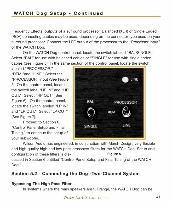
Frequency Effects) outputs of a surround processor. Balanced (XLR) or Single Ended(RCA) connecting cables may be used, depending on the connector type used on yoursurround processor. Connect the LFE output of the processor to the “Processor Input”of the WATCH Dog.
On the WATCH Dog control panel, locate the switch labeled “BAL/SINGLE.”Select “BAL” for use with balanced cables or “SINGLE” for use with single endedcables (See Figure 5). In the same section of the control panel, locate the switchlabeled “PROCESSOR,”“REM,”and “LINE.” Select the“PROCESSOR” input (See Figure5). On the control panel, locatethe switch label “HP IN” and “HPOUT.” Select “HP OUT” (SeeFigure 6). On the control panel,locate the switch labeled “LP IN”and “LP OUT.” Select “LP OUT”(See Figure 7).
Proceed to Section 6,“Control Panel Setup and FinalTuning,” to continue the setup ofyour subwoofer.
Wilson Audio has engineered, in conjunction with Marsh Design, very flexibleand high quality high and low pass crossover filters for the WATCH Dog. Setup andconfiguration of these filters is dis-cussed in Section 6 entitled “Control Panel Setup and Final Tuning of the WATCHDog.”
Section 5.2 - Connecting the Dog -Two-Channel System
Bypassing The High Pass FilterIn systems where the main speakers are full range, the WATCH Dog can be
W AT C H D o g S e t u p - C o n t i n u e d
Figure 5
42
configured more successfully without the use of the High Pass Filter. There is a normalbass roll-off that occurs naturally in your listening room. This effect acts like a six dBper octave low pass filter and rolls off the bass from your main speakers. By carefullyusing the WATCH Dog’s Low Pass filter controls, along with the Bass Equalization andPhase controls (discussed in Section 6), you can successfully integrate the main loud-speakers in your system with the WATCH Dog without the use of the High Pass Filter.
Make sure the WATCH Dog power is off during the connecting process. Locatethe input section of the WATCH Dog on the rear of the subwoofer (See Figure 4). Theleft and right “Line Level” inputs are used when the WATCH Dog is the subwoofer totwo main loudspeakers. The WATCH Dog automatically sums the information from theleft and right channels for the subwoofer. The WATCH Dog inputs are configured forboth balanced (XLR) and single ended (RCA) cables.
When connecting the WATCH Dog without the use of the High Pass Filter, asecond output from your preamplifier is required. If your preamplifier does not havetwo sets of outputs, consult with your dealer about using high quality “Y” connectorsto facilitate connecting your subwoofer. From one of the preamp outputs, connectyour preamp directly to your main amplifier. From a second set of preamp outputs,connect both left and right channels to the Line Level Input of the WATCH Dog.
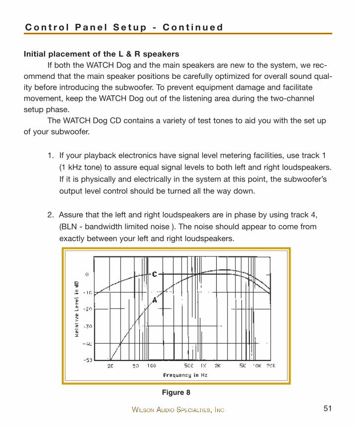
On the WATCH Dog control panel, locate the switch labeled “BAL,” and “SIN-GLE.” Select “BAL” for use with balanced cables, or “SINGLE” for use with singleended cables (See Figure 5). In the same section of the control panel, locate theswitch labeled “PROCESSOR,” “REM,” and “LINE.” Select the “LINE” input. On thecontrol panel, locate the switch label “HP IN,” “REM,” and “HP OUT” (see Figure 6).Select “HP OUT.” On the control panel, locate the switch labeled “LP IN,” “REM,” and“LP OUT” (See Figure 7). Select “LP IN.”
Proceed to Section 6, “Control Panel Setup and Final Tuning,” to continue thesetup of your subwoofer.
Utilizing The High Pass FilterThe WATCH Dog employs a high quality High Pass Filter as a part of its
crossover design. The High Pass Filter can be used to filter bass from the main loud-
43
speakers. This can be desirable in systems where the main loudspeakers have limitedbass dynamics or if the main power amplifier is low power.
Make sure the WATCH Dog power is off during the connecting process. On therear of the subwoofer, locate the Line Level inputs of the WATCH Dog. Connect thepreamplifier output, left and right, to the Line Level input of the WATCH Dog (SeeFigure 4). Use the XLR inputs for balanced cables or the RCA inputs for single-endedcables.
Locate the Line HP Output (See Figure 4) on the rear of the amplifier. Theseconnectors pass the high pass section of the signal to your main amplifier for yourloudspeakers. Connect the Line HP Output, left and right, of the WATCH Dog to theinputs of your power amplifier. Use the XLR inputs for balanced cables or the RCAinputs for single ended cables. On the WATCH Dog control panel, locate the switchlabeled “BAL,” and “SINGLE.” Select “BAL” for use with balanced cables, or “SIN-GLE” for use with single-ended cables (See Figure 5). In the same section of the con-trol panel, locate the switchlabeled “PROCESSOR,”“REM,” and “LINE.” Select the“LINE” input.
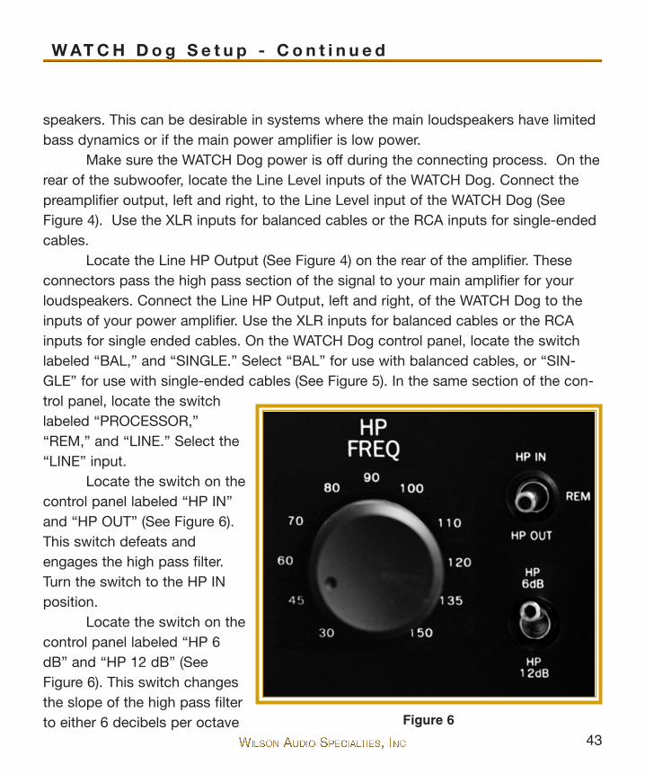
Locate the switch on thecontrol panel labeled “HP IN”and “HP OUT” (See Figure 6).This switch defeats andengages the high pass filter.Turn the switch to the HP INposition.
Locate the switch on thecontrol panel labeled “HP 6dB” and “HP 12 dB” (SeeFigure 6). This switch changesthe slope of the high pass filterto either 6 decibels per octave
W AT C H D o g S e t u p - C o n t i n u e d
Figure 6

44
or 12 decibels per octave. Theposition of this switch will be setin its final position in the finaltuning stages of the WATCHDog. For now, set the switch tothe 6 dB per octave position.
Proceed to Section 6,“Control Panel Setup and FinalTuning,” to continue the setup ofyour subwoofer.
Figure 7
45
W AT C H D o g S e t u p - C o n t i n u e d


48

49
Note: Before proceeding with the Control Panel setup and configuration,please connect your system as outlined in Section 5, which contains valuableinformation needed before proceeding further.
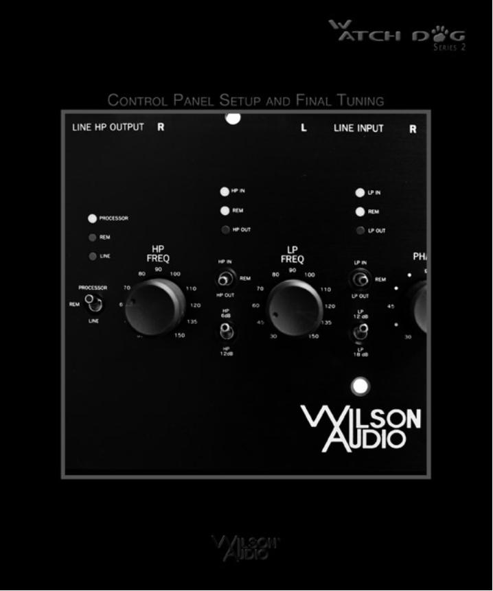
Section 6.0 - Control Panel Setup and Final TuningPreparation
In order to realize the full potential of your WATCH Dog, we recommend thatyou have a trained Wilson Audio Specialist install and perform the final adjustment andsetup of your subwoofer. Your dealer will have personnel trained in the art of WATCHDog setup. If you choose to do the installation yourself, here are some guidelines toassist you. These guidelines come from many years of experience and should be fol-lowed closely to ensure the best possible result from your WATCH Dog.
You will need the following items:
• Supplied WATCH Dog Setup CD• Supplied 5/32 T-handled Allen Wrench• Radio Shack dB Meter• Pen and paper to make notes
Using the Allen wrench, remove the top clear acrylic cover plate that protectsthe control panel. Double check the switch and control settings to ensure that they arein the proper positions as outlined in Section 5. In this section, you will be adjustingand fine tuning the WATCH Dog control panel.
Locate the main power switch on the rear of the WATCH Dog, below the ampli-fier heatsinks. Toggle the switch to the “on” position. This powers the WATCH Doginto the “standby” mode and can be left on. Locate the power switch on the front ofthe WATCH Dog, behind the grille. Depress the switch and check to see that the frontpanel LED is illuminated.
C o n t r o l P a n e l S e t u p a n d F i n a l Tu n i n g
50
Note: We recommend that you turn the main power switch on the rear ofamplifier to the off position and disconnect the power cord during lightningstorms or when you are away.
Section 6.1 - Notes From David A. Wilson on Using the Test CD
Wilson Audio has provided a test CD to aid you in the setup of your WATCHDog subwoofer. The following comments and recommendations refer most preciselyto the use of the WATCH Dog subwoofer in a two-channel music system. However,these procedures can also be used to optimize the WATCH Dog to the left and theright channels of a multi-channel home theater system.
Subwoofer PlacementThe WATCH Dog possesses sophisticated low pass filter control features, as
well as the ability to continuously vary phase angle. As a result, placement of theWATCH Dog is not as critical as with most other designs. The WATCH Dog can besuccessfully placed between and slightly behind the left and right speakers. However,because of its flexible control, the WATCH Dog is equally successfully placed in a vari-ety of locations in the listening room - such as on a side wall or behind the listener.
Filtering of LF to the Left & Right SpeakersWith two-channel music systems in moderate sized rooms, where high volumes
are not required, the left and right speakers are often run full range. This is particularlytrue when Wilson Audio speakers are used, as a reult of their low distortio and robustpower-handling capabilities. The usual rationale for this approach is that the “full-range” signal will lose some of its midrange and high frequency transparency goingthrough the active high pass crossover. While this is theoretically true, what is moreimportant is the more complex low frequency room interaction that will occur betweenthe subwoofer’s output and the full range output of the L and R channels. This LFinteraction is greatly reduced if LF to the L & R speakers is filtered out. For the great-est finesse in music reproduction you should experiment with both approaches.
51
Initial placement of the L & R speakersIf both the WATCH Dog and the main speakers are new to the system, we rec-
ommend that the main speaker positions be carefully optimized for overall sound qual-ity before introducing the subwoofer. To prevent equipment damage and facilitatemovement, keep the WATCH Dog out of the listening area during the two-channelsetup phase.
The WATCH Dog CD contains a variety of test tones to aid you with the set upof your subwoofer.
1. If your playback electronics have signal level metering facilities, use track 1
(1 kHz tone) to assure equal signal levels to both left and right loudspeakers.
If it is physically and electrically in the system at this point, the subwoofer’s
output level control should be turned all the way down.
2. Assure that the left and right loudspeakers are in phase by using track 4,
(BLN - bandwidth limited noise ). The noise should appear to come from
exactly between your left and right loudspeakers.
C o n t r o l P a n e l S e t u p - C o n t i n u e d
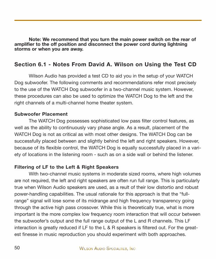
Figure 8

52
3. If you have either a spectrum analyzer or a sound pressure level (SPL) meter,
you should measure and document the in-room response of your L & R
loudspeakers, running full-range, without subwoofer contribution. This will
give you a baseline measurement. While you can measure each channel
individually, it is more expedient to measure both simultaneously using the
(Mono) test signals. Measurement locations for the microphone should
include one at ear height at the main listening location. Additional locations
could include two meters, both left and right, of the primary listening posi-
tion, as well as halfway between the primary position and the back wall.
These readings must be averaged together. Expect measurements taken
close to walls to show substantially more LF energy than those taken near
the center of the room. Use the dB-C weighting, or better yet, if available,
the “Flat”/ non-weighted scale of your instrument. See Figure 8 which com-
pares dB-A & dB-C weighting. The more commonly used dB-A scale, on the
other hand, is intended to correspond to the ear’s “frequency response” at
low SPL and should never be used to calibrate low frequency levels. Please
note that, even at 50 Hz, the dB-C scale is still down approximately 2 dB
relative to 800 Hz. Don’t be disappointed, therefore, if your dB-C scale
measurements show a gradual roll off in the bass. If your measurements do
follow the profiled roll off, it indicates a very linear speaker/room response.
Use track 2, (pink noise), for spectrum analysis measurements. For meas-
urements using a SPL meter, use tracks 6 through 16, (1/3 octave BLN
beginning at 200 Hz and going down to 20 Hz). Document your measured
results.
Warning: Tracks 17 through 27 are sine wave tones at the 1/3-octave cen-ter frequencies. These should not be used to perform in-room frequencyresponse estimates due to gross inaccuracies which will be created by standingwaves. Pure tones are included to scan for mechanical resonances and otherdistortions.
53
Notes Regarding the Interpretation of Measurements:
A. Use “slow” meter response ballistics to help average out thereading… and to keep from going crazy trying to read it!
B. Ears and meters are not directly interchangeable. They neithersample nor process the sound in a completely analogousmanner.
4. If you choose to use the high pass section of the WATCH Dog controller to
roll off bass to your main speakers, you can use your measured data to
select a low pass (LP) frequency. The suggested setting for the high pass
frequency is at the point where the measured frequency curve begins to
“roll-off,” specifically at the frequency that is minus three to minus six dB
(relative to the average level of the full-range response). If specific measure-
ments are not available, I like to start, as a general rule, at 50 Hz with an 18-
dB/octave LP slope. I believe that the vast majority of loudspeakers with
which the WATCH Dog will likely be partnered should have enough clean
output and power handling in the 40-50 Hz region to allow this approach.
However, some rooms exhibit so much loss in the LF that the L & R speak-
ers may have difficultly in that region and need help from the subwoofer up
to 60-80 Hz. Another scenario might include problematic room acoustics,
with a significant upper bass peak. In such a case, correction may be
achieved by running the WATCH Dog up to 120-140 Hz and using its EQ to
notch out the room peak. This is one area where acoustical measurements,
as described above, are of great benefit.
Introduction of The WATCH Dog Into Your System
5. Check to see that the L & R loudspeaker power amps are “Off” or on
C o n t r o l P a n e l S e t u p - C o n t i n u e d

54
“Standby.”
6. Ensure that all system cabling is correct and secure. At this point in the set
up process, the input switches should be configred properly, according to
instructions elsewhere in this manual. It is now time to optimize Level, Phase
and EQ settings.
7. If you are filtering the bass to your L & R speakers, select “HP In,” and set
the high pass frequency according to the acoustical measurements you
have taken. Start with HP 12 dB per octave slope.
8. Initially select the low pass frequency 10 % lower than the setting for the
high pass frequency.
9. Select “LP In” and LP 18-dB / octave slope.
10. Initially set the Phase control at 90°.
11.Select “EQ Out” at this point in the calibration.
12.The output level control should be in the “Min” position.
13.Turn on the program source components and pre-amplification.
14. After two minutes of stabilization time, turn on your WATCH Dog subwoofer.
15. After two additional minutes of stabilization time, turn on your L & R chan-
nel power amplifiers.
55
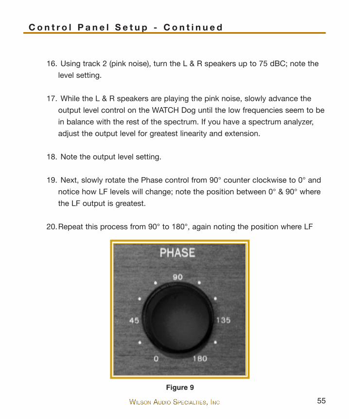
16. Using track 2 (pink noise), turn the L & R speakers up to 75 dBC; note the
level setting.
17. While the L & R speakers are playing the pink noise, slowly advance the
output level control on the WATCH Dog until the low frequencies seem to be
in balance with the rest of the spectrum. If you have a spectrum analyzer,
adjust the output level for greatest linearity and extension.
18. Note the output level setting.
19. Next, slowly rotate the Phase control from 90° counter clockwise to 0° and
notice how LF levels will change; note the position between 0° & 90° where
the LF output is greatest.
20.Repeat this process from 90° to 180°, again noting the position where LF
C o n t r o l P a n e l S e t u p - C o n t i n u e d
Figure 9
56
output is greatest. These two settings become your “semifinalists.”
21.Go to track 28 (drum and guitar music) and compare the sound of your two
Phase “semifinalists.” Listen for cleaner LF attack and greater weight to
select your “winner.” Note the winning setting.
22.Use two tracks, 29 and 32, to establish the WATCH Dog’s upper frequency
limit with the LP frequency control setting. What you are looking for is a set-
ting that is low enough to keep from adding artificial chestiness to the male
voice in track 32, yet high enough to provide convincing, linear low frequen-
cy continuity in track 29. Note the setting.
23.Using the same tracks (29 & 32) and similar listening-judgment criteria, opti-
mize the setting of HP frequency control, which establishes the low frequen-
cy limit of your L & R speakers. Note the setting.
24. At this point in the process, it is instructive to measure the acoustic
response of the combined L & R system a second time, but this time with
the addition of the subwoofer. Compare the results of this measurement with
your prior measurements made without the subwoofer. Document these new
measurements. You should now clearly observe more output below 40 Hz as
well as good linearity.
25.Now is a good time to experiment with different filter slopes. Simply follow
the same procedures as above, being careful to note all settings. This sec-
ond experiment can then be compared with the first, using music and meas-
urements. Pick the approach that gives the most satisfying musical results.
To EQ Or Not To EQ
57
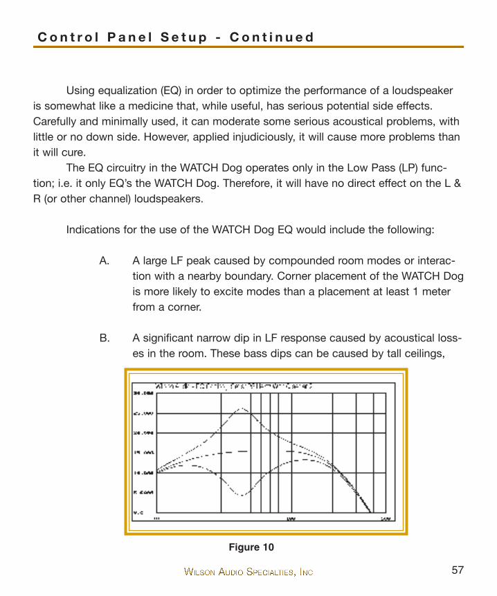
Using equalization (EQ) in order to optimize the performance of a loudspeakeris somewhat like a medicine that, while useful, has serious potential side effects.Carefully and minimally used, it can moderate some serious acoustical problems, withlittle or no down side. However, applied injudiciously, it will cause more problems thanit will cure.
The EQ circuitry in the WATCH Dog operates only in the Low Pass (LP) func-tion; i.e. it only EQ’s the WATCH Dog. Therefore, it will have no direct effect on the L &R (or other channel) loudspeakers.
Indications for the use of the WATCH Dog EQ would include the following:
A. A large LF peak caused by compounded room modes or interac-tion with a nearby boundary. Corner placement of the WATCH Dogis more likely to excite modes than a placement at least 1 meterfrom a corner.
B. A significant narrow dip in LF response caused by acoustical loss-es in the room. These bass dips can be caused by tall ceilings,
C o n t r o l P a n e l S e t u p - C o n t i n u e d
Figure 10

58
openings such as windows and doors (particularly near corners orat the middle of a long wall), or a small, non load-bearing wallwhich acts as a panel resonator bass trap.
These anomalies would show up in the measurements which you have takenabove.
26.Set the EQ level control at its “12:00” position, indicating zero gain.
27.Set the switch to “EQ In.”
28.Set the “EQ Freq” to correspond with
where you believe the problem frequency
is.
29.Set the “Q” control at its “12:00” position.
30.Depending on whether the acoustical
anomaly is a LF response peak or a dip,
either cut or boost the EQ with the level
control. If you use track 2 (pink noise) and
a spectrum analyzer, you can make these
adjustments and see (as well as hear) the
results in real time. If you do not have a
spectrum analyzer, you can still listen to
the changes in pink noise. Adjust for great-
est smoothness, then measure and docu-
ment your results. It has been my experience making adjust- Figure 11

59
ments in an attempt to achieve perfect flatness of response is misguided. Possibly thisis because the test signal (i.e., pink noise) causes a relatively continuous excitation ofresonances. This allows the amplitude to build up, appearing in measurements as alarge deviation from optimum. Much music on the other hand, because of its moretransient nature, may not cause these non-linearities to build up as much. Hence, thetendency to overcorrect relative to what the musical signal really requires. Therefore, Isuggest correcting about half the amplitude of the peak or dip, documenting yourresults, then listening to see if it makes more musical sense. Apply corrections only asneeded. To quote J. Gordon Holt, “If it measures good, but sounds bad… It is bad.”
Advancing the EQ Q control allows you to narrow and sharpen the EQ boost orcut. At the maximum Q setting of 2, the equalization is pretty specific, but can alsoalter harmonic structures. Turning the Q control CCW to 0.2 results in a very broad,less frequency-selective adjustment, which usually will not provide enough specificcorrection.
Section 6.2 - Break-in Period
All audio equipment will sound its best after the components have been bro-ken-in for some period of use. Wilson Audio breaks in the woofer of your WATCH Dogfor a 12 hour period. All drivers are then tested, calibrated, and matched for theiracoustical properties. Some break-in is also required of the Control Panel and theamplifier. Wilson Audio recommends that you begin final positioning of your WATCHDog subsequent to the break-in process. In your listening room, expect 25-50% ofbreak-in to be complete after two hours of playing music at a moderate volume.Ninety percent of break-in is complete after 24 hours of playing. Playing a “discrepeat” overnight can accomplish this task quickly. Wilson Audio often uses chambermusic to accomplish this process.
C o n t r o l P a n e l S e t u p - C o n t i n u e d


62

63
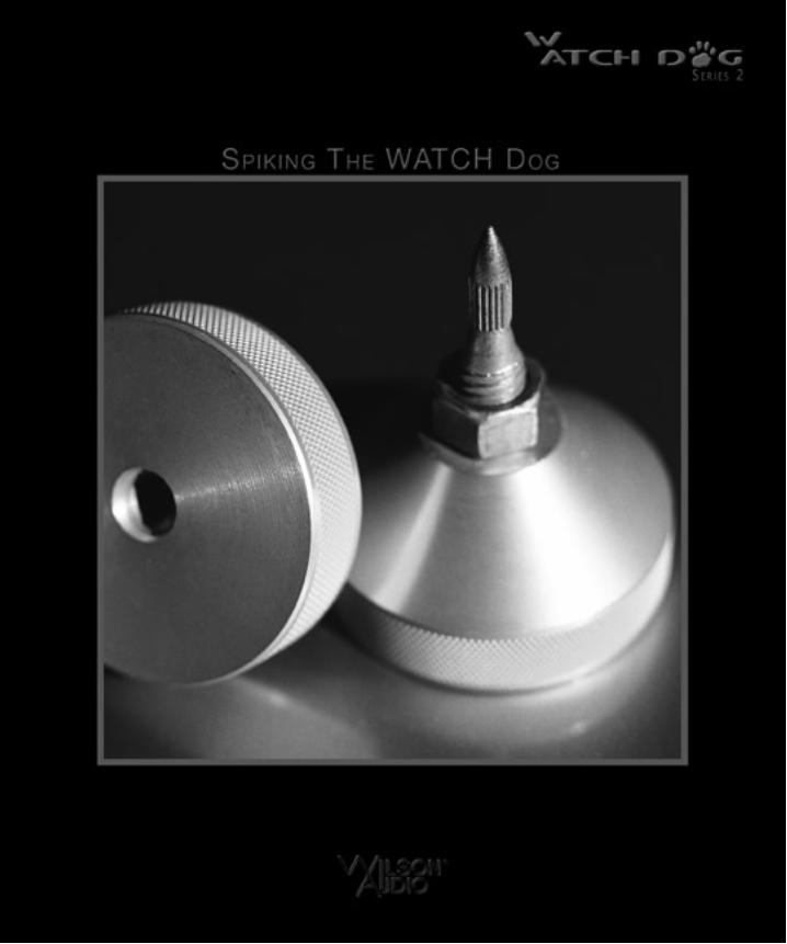
Section 7.0 - WATCH Dog Spikes
The WATCH Dog comes with a set of heavy duty spikes that provide acousticalisolation as well as optimal height placement for your WATCH Dog. Brass disks that fitbeneath the spikes are included for installations where spikes might damage the floorsurface (such as wood floors).
After determining the WATCH Dog’s position, assemble the spikes as follows:
Assembly
1. Insert threaded bolts in the bolt holes in the front of the subwoofer until they
are flush with the inner surface visible through the acoustic port. Make sure
the Allen key end is facing downward.
2. Screw the acoustical diode onto the bolt until it fits snugly against the bot-
tom of the WATCH Dog. Do not overtighten.
4. Screw the spike (with nut) all the way in until it just touches the bolt. Do not
tighten the nut at this time.
5. Repeat steps 1 through 4 with the other spikes.
6. Using a bubble level, adjust the spikes so that the WATCH Dog is level and
so that all of the spikes are making equal contact with the hard surface
beneath.
The spikes, installed properly, discouple the WATCH Dog from the floor, reduc-ing resonances within the room. They also provide a stable platform for the WATCHDog to launch bass energy into the room. The result is cleaner, faster, more dynamicbass, with improved extension and linearity.
S p i k i n g t h e W AT C H D o g


66

67
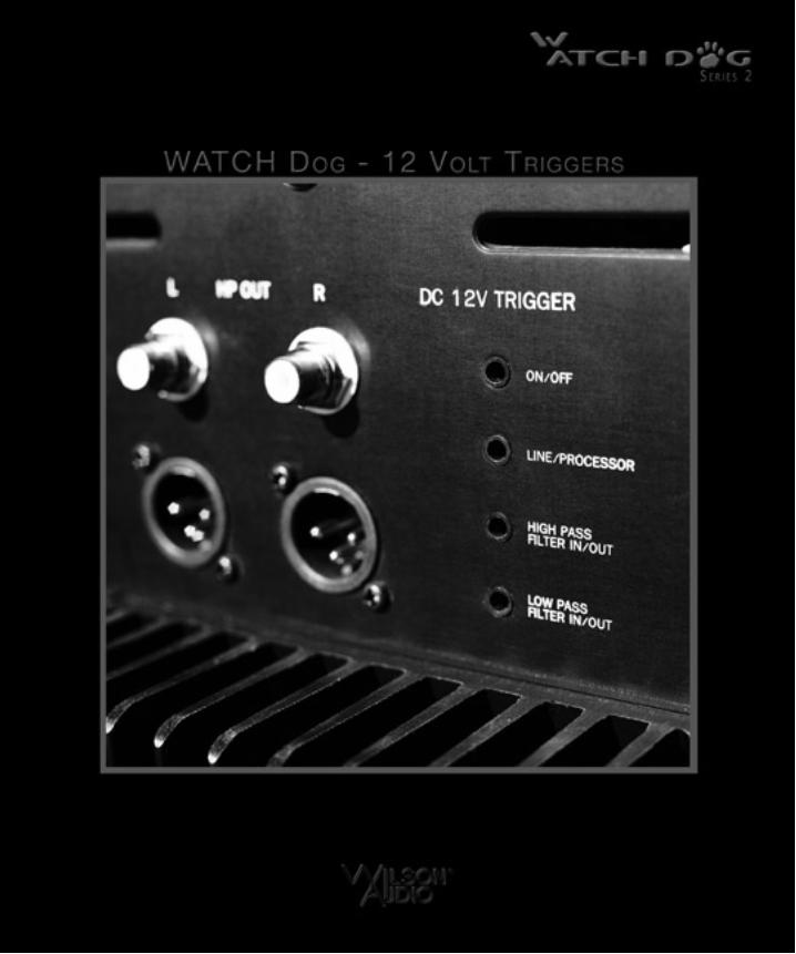
Section 8.0 - Twelve-Volt Trigger Controls
Certain features of the WATCH Dog are controllable via a series of twelve-volttriggers. This allows remote control access ofthese features by outside control systems,Audio/Video Controllers, etc. This providesmore convenient and seamless operation of theWATCH Dog within home theaters and com-plex audio systems.
The twelve-volt triggers are connectedvia standard DC ports located adjacent to theaudio inputs on the rear of the WATCH Dog.The following features can be switchedbetween two states: On/Off (Stand By);Line/Processor; High Pass Filter In/Out; LowPass Filter In/Out.
To access control of one of these fourfeatures via its twelve-volt trigger, move theswitch corresponding to that function to the“Rem” position. The switches forLine/Processor, High Pass Filter In/Out, andLow Pass Filter In/Out are located on the maincontrol panel. The switch for the Stand ByOn/Off Feature is located on the rear of thesubwoofer. When a function switch is in the“Rem” position, that feature can only be con-troled through the twelve-volt trigger.
Please Note: Only the switches rele-vant to the features to be remote controlledshould be switched to the “Rem” position.
C o n t r o l l i n g t h e W AT C H D o g
Figure 12

68
Toggling the switch to theremote position without atwelve volt trigger connectedto that switch will potentiallyresult in your WATCH Dogbeing improperly configured.The trigger switch defaultsto the zero volt position withnothing connected.
The trigger is designedbe attached to two-state, relayswitches which togglebetween zero volts and twelvevolts. Several Audio/Videocontrollers feature twelve-voltrelay triggers, the status ofwhich are associated withselected modes. These can be
used in conjunction with the WATCHDog relay switches to configure yoursubwoofer ideally for those corre-sponding modes. Similarly, controlsystems such as Crestron, AMX andothers have the option for interfacingwith controllable devices via twelve-volt relay triggers. Consult youraudio specialist or installer for moredetails.
The twelve-volt triggers aretwo-state switches: the presence ofzero volts (no voltage) on the input of
Figure 13
Figure 14
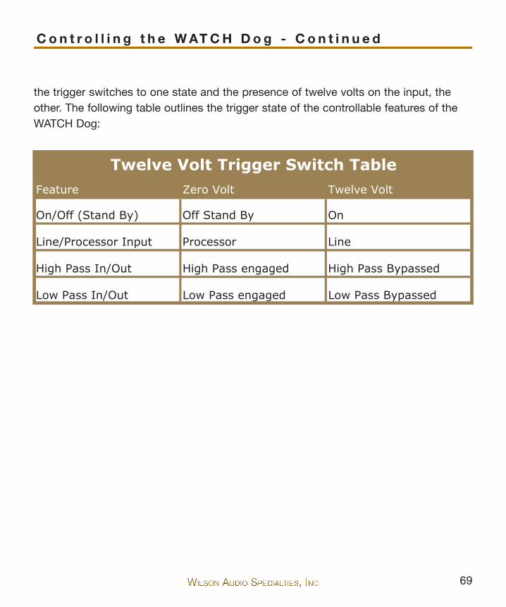
69
the trigger switches to one state and the presence of twelve volts on the input, theother. The following table outlines the trigger state of the controllable features of theWATCH Dog:
C o n t r o l l i n g t h e W AT C H D o g - C o n t i n u e d
Feature Zero Volt Twelve Volt
On/Off (Stand By) Off Stand By On
Line/Processor Input Processor Line
High Pass In/Out High Pass engaged High Pass Bypassed
Low Pass In/Out Low Pass engaged Low Pass Bypassed
Twelve Volt Trigger Switch Table


72
73
Section 9.0 - Care of Your WATCH Dog
Your WATCH Dog subwoofer enclosure is hand-painted with WilsonGloss™paint and hand-polished to a high luster. While the paint seems quite dry to the touch,final curing and complete hardening takes place over a period of several weeks. Toprotect the finish of the WATCH Dog during final manufacturing, shipment, and setupin your listening room, we have applied a removable layer of protective film over thepainted surface. We recommend that this film be left in place during the positioningprocess to prevent damage to the painted surface of your subwoofer. Once you havedetermined the WATCH Dog’s final position, remove the film by peeling it off. Do notleave this film on indefinitely as it will leave impressions on the paint.
It is important that the delicate paint finish of the WATCH speakers be dustedcarefully with the dust cloth, which has been provided. We recommend that the fol-lowing procedure be observed when dusting the speakers:
• Blow off all loose dust.• Using the dust cloth as a brush, gently whisk off any remaining
loose dust.• Shake out the dust cloth.• Dust the finish, using linear motions in one direction parallel to the
floor. Avoid using circular or vertical motions.
Because the paint requires a period of several weeks to fully cure, we recom-mend that no cleaning fluids, such as glass cleaners, be used during this initial periodof time. When the paint is fully cured, heavy finger prints and other minor smudgesmay be removed with a glass cleaner. When cleaning the painted surface of your sub-woofer, always use the dust cloth. Stronger solvents are not recommended under anycircumstances as they may damage the paint. Consult your dealer for further informa-tion if required.
Periodic polishing may be desired over the years to maintain the high luster ofthe finish. We recommend a nonabrasive, carnauba-based wax and a soft cloth.
C a r e o f t h e F i n i s h

74
Several pieces of the Center channel are made of black “X” material. Wherethis material is not painted, it will require periodic polishing to maintain the semiglossfinish. We recommend a silicone-based plastic polish (available at automotive supplystores).

75
C a r e o f t h e F i n i s h - C o n t i n u e d


78
79
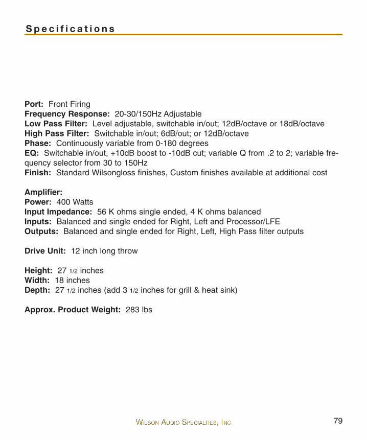
Port: Front FiringFrequency Response: 20-30/150Hz AdjustableLow Pass Filter: Level adjustable, switchable in/out; 12dB/octave or 18dB/octaveHigh Pass Filter: Switchable in/out; 6dB/out; or 12dB/octavePhase: Continuously variable from 0-180 degreesEQ: Switchable in/out, +10dB boost to -10dB cut; variable Q from .2 to 2; variable fre-quency selector from 30 to 150HzFinish: Standard Wilsongloss finishes, Custom finishes available at additional cost
Amplifier:Power: 400 WattsInput Impedance: 56 K ohms single ended, 4 K ohms balancedInputs: Balanced and single ended for Right, Left and Processor/LFEOutputs: Balanced and single ended for Right, Left, High Pass filter outputs
Drive Unit: 12 inch long throw
Height: 27 1/2 inchesWidth: 18 inchesDepth: 27 1/2 inches (add 3 1/2 inches for grill & heat sink)
Approx. Product Weight: 283 lbs
S p e c i f i c a t i o n s


82
83
LI
Limited WarrantySubject to the conditions set forth herein, Wilson Audio warrants its loudspeak-
ers to be free of manufacturing defects in material and workmanship for the WarrantyPeriod. The Warranty Period is a period of 90 days from the date of purchase by theoriginal purchaser, or if both of the following two requirements are met, the WarrantyPeriod is a period of five (5) years from the date of purchase by the original purchaser:
Requirement No. 1. No later than 30 days after product delivery to the
customer, the Warranty Registration Form must have been returned by the
customer to Wilson Audio;
Requirement No. 2. The product must have been professionally installed
by the Wilson Audio dealer that sold the product to the customer.
FAILURE TO COMPLY WITH EITHER REQUIREMENT NO. 1 OR REQUIRE-MENT NO. 2 WILL RESULT IN THE WARRANTY PERIOD BEING LIMITED TO A PERI-OD OF 90 DAYS ONLY.
ConditionsThis Limited Warranty is also subject to the following conditions and limitations.
The Limited Warranty is void and inapplicable if the product has been used or handledother than in accordance with the instructions in the owner’s manual, or has beenabused or misused, damaged by accident or neglect or in being transported, or if theproduct has been tampered with or service or repair of the product has been attempt-ed or performed by anyone other than Wilson Audio, an authorized Wilson Audio
Wilson AudioLimited Warranty
Terms & Conditions
84
Dealer Technician or a service or repair center authorized by Wilson Audio to serviceor repair the product. Contact Wilson Audio at (801) 377-2233 for information on loca-tion of Wilson Audio Dealers and authorized service and repair centers. Most repairscan be made in the field. In instances where return to Wilson Audio’s factory isrequired, the dealer or customer must first obtain a return authorization. Purchasermust pay for shipping to Wilson Audio, and Wilson Audio will pay for shipping of itschoice to return the product to purchaser. A RETURNED PRODUCT MUST BEACCOMPANIED BY A WRITTEN DESCRIPTION OF THE DEFECT. Wilson Audioreserves the right to modify the design of any product without obligation to purchasersof previously manufactured products and to change the prices or specifications of anyproduct without notice or obligation to any person.
RemedyIn the event that the product fails to meet the above Limited Warranty and the
conditions set forth herein have been met, the purchaser’s sole remedy under thisLimited Warranty shall be to: (1) contact an authorized Wilson Audio Dealer within theWarranty Period for service or repair of the product without charge for parts or labor,which service or repair, at the Dealer’s option, shall take place either at the locationwhere the product is installed or at the Dealer’s place of business; or (2) if purchaserhas timely sought service or repair and the product cannot be serviced or repaired bythe Dealer, then purchaser may obtain a return authorization from Wilson Audio and atpurchaser’s expense return the product to Wilson Audio where the defect will be recti-fied without charge for parts or labor.
Warranty is Limited to Original PurchaserThis Limited Warranty is for the sole benefit of the original purchaser of the cov-
ered product and shall not be transferred to a subsequent purchaser of the product,unless the product is purchased by the subsequent purchaser from an authorizedWilson Audio Dealer who has certified the product in accordance with Wilson Audiostandards and requirements and the certification has been accepted by Wilson Audio,

85
in which event the Limited Warranty for the product so purchased and certified shallexpire at the end of the original Warranty Period applicable to the product.
Demonstration EquipmentEquipment, while used by an authorized dealer for demonstration purposes, is
warranted to be free of manufacturing defects in materials and workmanship for aperiod of five (5) years from the date of shipment to the dealer. Demo equipmentneeding warranty service may be repaired on-site or, if necessary, correctly packedand returned to Wilson Audio by the dealer at dealer’s sole expense. Wilson Audio willpay return freight of its choice. A returned product must be accompanied by a writtendescription of the defect. Dealer owned demonstration equipment sold at retail withintwo (2) years of date of shipment to the dealer is warranted to the first retail customerto be free of manufacturing defects in materials and workmanship for the same timeperiods as if the product had originally been bought for immediate resale to the retailcustomer. Wilson Audio products are warranted for a period of 90 days, unlessextended to 5 years, as provided above, by return and filing of completed WarrantyRegistration at Wilson Audio within 30 days after product delivery to customer and theproduct was professionally installed by the Wilson Audio Dealer that sold the productto the customer.
MiscellaneousALL EXPRESS AND IMPLIED WARRANTIES NOT PROVIDED FOR HEREIN ARE
HEREBY EXPRESSLY DISCLAIMED. ANY LEGALLY IMPOSED IMPLIED WAR-RANTIES RELATING TO THE PRODUCT SHALL BE LIMITED TO THE DURATION OFTHIS LIMITED WARRANTY. THIS LIMITED WARRANTY DOES NOT EXTEND TO ANYINCIDENTAL OR CONSEQUENTIAL COSTS OR DAMAGES TO THE PURCHASER.Some states do not allow limitations on how long an implied warranty lasts or anexclusion or limitation of incidental or consequential damages, so the above limita-tions or exclusions may not apply to you. This Limited Warranty gives you specificlegal rights, and you may also have other rights, which vary, from state to state.

86

87