Embed Size (px)
Citation preview
2
WAT C H C E N T E R C H A N N E L O W N E R ’ S M A N U A L
Wilson Audio® is a registered trademark of Wilson Audio Specialties, Inc.
Cub®, Sophia®, WATT/Puppy®, MAXX®, X-1/Grand SLAMM®, WAMM®, and Alexandria® areregistered trademarks of Wilson Audio Specialties, Inc.
WATCH Center™, WATCH Surround™, WATCH Dog™, and Duette™ are trademarks of WilsonAudio Specialties, Inc.
This manual was produced by the Wilson Audio Engineering Department in cooperation withSales and Marketing. The information contained herein is subject to change without notice. CurrentRevision 3.0. If you are in need of a more recent manual, please contact your dealer.
The information in this manual is the sole property of Wilson Audio Specialties, Inc. Any repro-duction, in whole or in part, without the express written permission of Wilson Audio Specialties, Inc., isprohibited. No material contained herein may be transmitted in any form or by any means, electronic ormechanical, for any purpose, without the express written permission of Wilson Audio Specialties, Inc.
3
Sect ion 1 - WATCH Introduct ion . . . . . . . . . . . . . . . . . . . . . . . . . . . . . . . . . . . . .11
Sect ion 1.1- Appl icat ions . . . . . . . . . . . . . . . . . . . . . . . . . . . . . . . . . . . . . . . . . . . . . .11
Des ign Cons iderat ions . . . . . . . . . . . . . . . . . . . . . . . . . . . . . . . . . . . . . . . . . . . . . .12
Sect ion 1.2 WATCH Package . . . . . . . . . . . . . . . . . . . . . . . . . . . . . . . . . . . . . . . . . .13
WATCH Center . . . . . . . . . . . . . . . . . . . . . . . . . . . . . . . . . . . . . . . . . . . . . . . . . . . . . . . .13
WATCH Surround . . . . . . . . . . . . . . . . . . . . . . . . . . . . . . . . . . . . . . . . . . . . . . . . . . . .14
WATCH Dog . . . . . . . . . . . . . . . . . . . . . . . . . . . . . . . . . . . . . . . . . . . . . . . . . . . . . . . . . . . .15
Conc lus ion . . . . . . . . . . . . . . . . . . . . . . . . . . . . . . . . . . . . . . . . . . . . . . . . . . . . . . . . . . . . . .15
Sect ion 2 - In Your Room . . . . . . . . . . . . . . . . . . . . . . . . . . . . . . . . . . . . . . . . . . . . . . .21Slap Echo . . . . . . . . . . . . . . . . . . . . . . . . . . . . . . . . . . . . . . . . . . . . . . . . . . . . . . . . . . . . . . 21
Stand ing Waves . . . . . . . . . . . . . . . . . . . . . . . . . . . . . . . . . . . . . . . . . . . . . . . . . . . . . .23
Comb F i l te r E f fect . . . . . . . . . . . . . . . . . . . . . . . . . . . . . . . . . . . . . . . . . . . . . . . . . . . .25
Sect ion 2.1 - Resonance . . . . . . . . . . . . . . . . . . . . . . . . . . . . . . . . . . . . . . . . . . . . . . . .27
Structura l Resonance . . . . . . . . . . . . . . . . . . . . . . . . . . . . . . . . . . . . . . . . . . . . . . . .27
Ai r Vo lume Resonance . . . . . . . . . . . . . . . . . . . . . . . . . . . . . . . . . . . . . . . . . . . . . .28
Sect ion 3 - In i ta l System Setup . . . . . . . . . . . . . . . . . . . . . . . . . . . . . . . . . . . . . .33System Setup Procedure . . . . . . . . . . . . . . . . . . . . . . . . . . . . . . . . . . . . . . . . . .33
Room Shapes . . . . . . . . . . . . . . . . . . . . . . . . . . . . . . . . . . . . . . . . . . . . . . . . . . . . . . . . . .34
Zone o f Neut ra l i t y . . . . . . . . . . . . . . . . . . . . . . . . . . . . . . . . . . . . . . . . . . . . . . . . . . . .36
Sect ion 3.1 - Choosing a Listening Posit ion . . . . . . . . . . . . . . . . . . . .38
Speaker P lacement vs . L is ten ing Pos i t ion . . . . . . . . . . . . . . . . . . . .38
Speaker Or ientat ion . . . . . . . . . . . . . . . . . . . . . . . . . . . . . . . . . . . . . . . . . . . . . . . . . .39
Center Channe l . . . . . . . . . . . . . . . . . . . . . . . . . . . . . . . . . . . . . . . . . . . . . . . . . . . . . . . .39
Surround Channe l . . . . . . . . . . . . . . . . . . . . . . . . . . . . . . . . . . . . . . . . . . . . . . . . . . . .41
WATCH Dog . . . . . . . . . . . . . . . . . . . . . . . . . . . . . . . . . . . . . . . . . . . . . . . . . . . . . . . . . . . .42
TA B L E O F C O N T E N T S
4
Sect ion 3.2 - In i t ia l Setup Summary . . . . . . . . . . . . . . . . . . . . . . . . . . . . . . . .42
Sect ion 4 - WATCH Center Channel Setup . . . . . . . . . . . . . . . . . . . . . . .47Setup Procedure . . . . . . . . . . . . . . . . . . . . . . . . . . . . . . . . . . . . . . . . . . . . . . . . . . . . . .48
Center Channe l Sp ike Assembly . . . . . . . . . . . . . . . . . . . . . . . . . . . . . . . .48
Sect ion 4.1 - Measured Listening Posit ion . . . . . . . . . . . . . . . . . . . . . .50
Room Setup . . . . . . . . . . . . . . . . . . . . . . . . . . . . . . . . . . . . . . . . . . . . . . . . . . . . . . . . . . . .50
Center Channe l Conf igurat ions . . . . . . . . . . . . . . . . . . . . . . . . . . . . . . . . . .51
Sect ion 4.2 - Center Channel on Floor . . . . . . . . . . . . . . . . . . . . . . . . . . . .53
Sect ion 4.3- Center Channel on Stand . . . . . . . . . . . . . . . . . . . . . . . . . . . .54
Sect ion 4.4 - Center Channel on Custom Stand or Shelf . .56
Sect ion 4.5 -Center Channel Mounted to Cei l ing . . . . . . . . . . . .59
Custom Made Mount ing Bracket Requ i rements . . . . . . . . . . . .59
Mount ing Center Channe l above Te lev is ion . . . . . . . . . . . . . . . . . .62
Setup . . . . . . . . . . . . . . . . . . . . . . . . . . . . . . . . . . . . . . . . . . . . . . . . . . . . . . . . . . . . . . . . . . . .63
Sect ion 4.6 - Center Channel F inal Setup . . . . . . . . . . . . . . . . . . . . . . . .65
Phase De lay Correct ion (PDC) - Stand or F loor Mounted 65
PDC - Ce i l ing or Other Custom Locat ion . . . . . . . . . . . . . . . . . . . . . .66
Speaker Cab les . . . . . . . . . . . . . . . . . . . . . . . . . . . . . . . . . . . . . . . . . . . . . . . . . . . . . . . . 68
Spade Lugs . . . . . . . . . . . . . . . . . . . . . . . . . . . . . . . . . . . . . . . . . . . . . . . . . . . . . . . . . . . .68
Connect ion o f the Center to the Power Ampl i f ie r . . . . . . . . . .69
Center Channe l Setup Completed . . . . . . . . . . . . . . . . . . . . . . . . . . . . . .70
Sect ion 5 - F inal System Tuning and Voicing . . . . . . . . . . . . . . . . . . .75
Sect ion 5.1 - Left and Right Channels . . . . . . . . . . . . . . . . . . . . . . . . . . . .76
Determin ing Front to Back D is tance . . . . . . . . . . . . . . . . . . . . . . . . . . . .76
WAT C H C E N T E R C H A N N E L O W N E R ’ S M A N U A L
5
TA B L E O F C O N T E N T S
Determin ing S ide to S ide D is tance . . . . . . . . . . . . . . . . . . . . . . . . . . . . . .77
Sect ion 5.2 - Integrat ing the WATCH System .. . . . . . . . . . . . . . . . . . .78
In tegrat ing the WATCH Center . . . . . . . . . . . . . . . . . . . . . . . . . . . . . . . . . . . .79
Image He ight . . . . . . . . . . . . . . . . . . . . . . . . . . . . . . . . . . . . . . . . . . . . . . . . . . . . . . . . . .80
Center Rotat ion . . . . . . . . . . . . . . . . . . . . . . . . . . . . . . . . . . . . . . . . . . . . . . . . . . . . . . . .80
Reset t ing the PDC .. . . . . . . . . . . . . . . . . . . . . . . . . . . . . . . . . . . . . . . . . . . . . . . . . . .81
Integrat ing the Sur round Channe ls . . . . . . . . . . . . . . . . . . . . . . . . . . . . . .82
Integrat ing the WATCH Dog . . . . . . . . . . . . . . . . . . . . . . . . . . . . . . . . . . . . . .83
Sect ion 6.0 - Care of the Finish . . . . . . . . . . . . . . . . . . . . . . . . . . . . . . . . . . . . .87Remov ing Protect ive F i lm . . . . . . . . . . . . . . . . . . . . . . . . . . . . . . . . . . . . . . . . . .87
Dust ing the WATCH Center . . . . . . . . . . . . . . . . . . . . . . . . . . . . . . . . . . . . . . . .88
Sect ion 6.1 - Care of the Gri l les . . . . . . . . . . . . . . . . . . . . . . . . . . . . . . . . . . . .89
Sect ion 6.2 - Break-in Per iod . . . . . . . . . . . . . . . . . . . . . . . . . . . . . . . . . . . . . . . .89
Sect ion 6.3 - Enclosure Technology . . . . . . . . . . . . . . . . . . . . . . . . . . . . . . . .90
Adhes ive . . . . . . . . . . . . . . . . . . . . . . . . . . . . . . . . . . . . . . . . . . . . . . . . . . . . . . . . . . . . . . . .90
Depth o f Des ign . . . . . . . . . . . . . . . . . . . . . . . . . . . . . . . . . . . . . . . . . . . . . . . . . . . . . .91
Sect ion 7 - Troubleshoot ing . . . . . . . . . . . . . . . . . . . . . . . . . . . . . . . . . . . . . . . . . . .95
Sect ion 8 -Center Channel Specif icat ions . . . . . . . . . . . . . . . . . . . . .101Spec i f icat ions . . . . . . . . . . . . . . . . . . . . . . . . . . . . . . . . . . . . . . . . . . . . . . . . . . . . . . . .101
Dimens ions . . . . . . . . . . . . . . . . . . . . . . . . . . . . . . . . . . . . . . . . . . . . . . . . . . . . . . . . . . . .101
Sect ion 9 -Geometr ic Al ignment Table . . . . . . . . . . . . . . . . . . . . . . . . . .107
Sect ion 9.1 - Center on Floor - No Spacers . . . . . . . . . . . . . . . .109
6
Sect ion 9.2 - Center on Floor - One Spacer . . . . . . . . . . . . . . . . . .110
Sect ion 9.3 -Center on Floor - Two Spacers . . . . . . . . . . . . . . . . . .111
Sect ion 9.4- Center on Stand - Spike and Nut Only . . . . . .112
Sect ion 9.5 -Center on Stand - Spike, Nut , and Diode . . . .113
Sect ion 10 - Warranty Information . . . . . . . . . . . . . . . . . . . . . . . . . . . . . . . .117L imi ted Warranty . . . . . . . . . . . . . . . . . . . . . . . . . . . . . . . . . . . . . . . . . . . . . . . . . . . .117
Remedy . . . . . . . . . . . . . . . . . . . . . . . . . . . . . . . . . . . . . . . . . . . . . . . . . . . . . . . . . . . . . . . .118
Warranty L imi ted to Or ig ina l Purchaser . . . . . . . . . . . . . . . . . . . . . .119
Demonst ra t ion Equ ipment . . . . . . . . . . . . . . . . . . . . . . . . . . . . . . . . . . . . . . . .119
Misce l laneous . . . . . . . . . . . . . . . . . . . . . . . . . . . . . . . . . . . . . . . . . . . . . . . . . . . . . . . .120
WAT C H C E N T E R C H A N N E L O W N E R ’ S M A N U A L

7
TA B L E O F C O N T E N T S


10
WAT C H C E N T E R C H A N N E L O W N E R ’ S M A N U A L
11
Sect i on 1 - WATCH In t roduct ion
If your passion is home theater, and you have sought the full sensory experi-
ence created as your eyes absorb the vision and your skin awakens to the power of
the sound, Wilson Audio has your answer. Introducing WATCH.
While all Wilson speakers are designed to take full advantage of today’s pop-
ular multi-channel formats, WATCH is the first Wilson system designed from the
ground up to excel specifically at home theater performance. Best of all, it comes
in a package as small or as large as you desire.
The fact is, you haven’t truly experienced home theater until you’ve felt the
impact, power, and passion of a film score the way the director intended it, and no
company will deliver this passion like Wilson Audio. That’s why in the past
decade, more blockbuster hits have been mixed, composed, or recorded using
Wilson Audio than any other loudspeaker.
S e c t i o n 1 . 1 - A p p l i c a t i o n s
For more than 20 years, Wilson Audio loudspeakers have set the standard
for performance in a wide variety of two-channel audio and multichannel home
theater applications. The WATCH (Wilson Audio Theater Come Home) surround
system was designed to offer a more compact and versatile home theater option for
those with limited space. Purchasing a surround system design by Wilson Audio
insures the very best possible integration with your Wilson Audio stereo loud-
S E C T I O N 1 - I N T R O D U C T I O N
12
WAT C H C E N T E R C H A N N E L O W N E R ’ S M A N U A L
speakers. The Watch system is designed to integrate with the Sophia,
WATT/Puppy, MAXX and, in many instances, the Alexandria.
Using structural enclosure, speaker driver, and geometric time alignment
technologies developed for the WATT/Puppy, MAXX, and the X-1 Grand SLAMM,
the WATCH system is truly the thoroughbred of its class and is well-suited to
carry on the heritage of Wilson Audio speakers.
One of David Wilson’s most important criteria in speaker development is
that a speaker meets the accuracy and dynamic demands of studio monitoring, ana-
lytical hardware and software evaluation, and, of course, critical music and theater
sound track listening. Therefore, the WATCH has been designed to deliver all of
the speed, dynamics, and musical accuracy to satisfy even the most demanding of
music lovers. The WATCH system will provide years of satisfaction whether listen-
ing to two-channel audio, multi-channel audio, or today’s latest movie sound track
technology.
The WATCH has also been engineered to take full advantage of today’s
multi-channel surround formats, especially the latest AC-3 (Dolby Digital), THX,
and DTS (Digital Theater Systems) formats. The WATCH will provide the speed,
dynamic impact, and realism you have come to expect in a high-performance home
theater system.
Design Considerat ions
Your WATCH system has been designed to perform all of the specific func-
13
tions of a high-performance home theater system. This was a difficult task because
of the many interactions that occur in a home theater environment. Because the
WATCH system was designed in-house and voiced with a variety of Wilson speak-
ers, you can be sure that the driver blend will be excellent whether your system
includes Sophias or Alexandrias. To accomplish this task, David Wilson and his
engineering department used some extraordinary material and enclosure tech-
niques.
S e c t i o n 1 . 2 W A T C H P a c k a g e
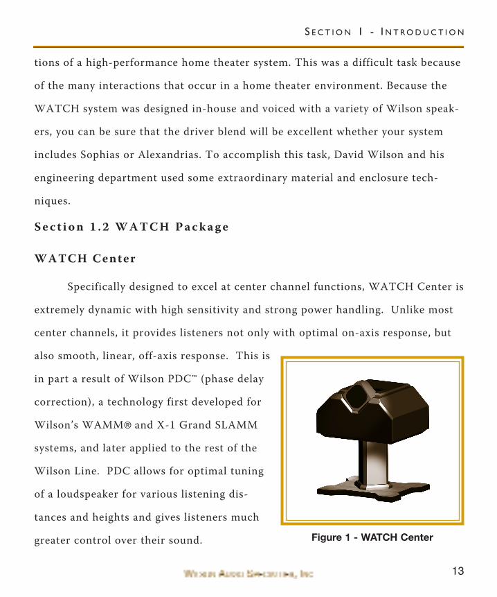
WATCH Center
Specifically designed to excel at center channel functions, WATCH Center is
extremely dynamic with high sensitivity and strong power handling. Unlike most
center channels, it provides listeners not only with optimal on-axis response, but
also smooth, linear, off-axis response. This is
in part a result of Wilson PDC™ (phase delay
correction), a technology first developed for
Wilson’s WAMM® and X-1 Grand SLAMM
systems, and later applied to the rest of the
Wilson Line. PDC allows for optimal tuning
of a loudspeaker for various listening dis-
tances and heights and gives listeners much
greater control over their sound.
S E C T I O N 1 - I N T R O D U C T I O N
Figure 1 - WATCH Center
14
WAT C H C E N T E R C H A N N E L O W N E R ’ S M A N U A L
The WATCH Center Channel was designed from the ground up as a center
channel. It is not merely a standard speaker that was tipped onto its side. The
Center Channel was voiced and optimized to truly represent dialogue for movies as
well as music and vocals when used in a multi-channel audio setup.
Of course, WATCH Center lives up to Wilson high standards of cutting edge
design, superior build quality, and stunning sonic performance. WATCH Center is
shielded and is available with a matching stand.
WATCH Surround
WATCH Surround is a perfect example of performance disproportionate to
size. With strong power handling capacity and low end frequency response reach-
ing 45Hz, this speaker will take your surround sound to new heights. Unlike most
surround speakers, WATCH Surround is more than a noisemaker. It brings accu-
racy, dynamics, and emotion to your theater. With it’s gorgeous Mirrorgloss™ fin-
ish, it looks right at home on your wall.
WATCH Surround also minimizes wall/ceiling resonant interactions through
its advanced mounting system. Perhaps the greatest challenge for a mounted
speaker, these interactions cause coloration of sound; accentuating some frequen-
cies and effectively masking others. Using state-of-the-art materials technology
first developed for the X-1 Grand SLAMM, WATCH Surround provides stunning
results.
The Surround wall mounting bracket allows the Surround to be spiked to the
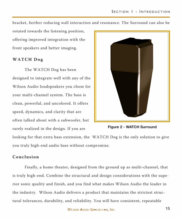
15
bracket, further reducing wall interaction and resonance. The Surround can also be
rotated towards the listening position,
offering improved integration with the
front speakers and better imaging.
WATCH Dog
The WATCH Dog has been
designed to integrate well with any of the
Wilson Audio loudspeakers you chose for
your multi-channel system. The bass is
clean, powerful, and uncolored. It offers
speed, dynamics, and clarity that are
often talked about with a subwoofer, but
rarely realized in the design. If you are
looking for that extra bass extension, the WATCH Dog is the only solution to give
you truly high-end audio bass without compromise.
Conclusion
Finally, a home theater, designed from the ground up as multi-channel, that
is truly high-end. Combine the structural and design considerations with the supe-
rior sonic quality and finish, and you find what makes Wilson Audio the leader in
the industry. Wilson Audio delivers a product that maintains the strictest struc-
tural tolerances, durability, and reliability. You will have consistent, repeatable
S E C T I O N 1 - I N T R O D U C T I O N
Figure 2 - WATCH Surround
16
performance, unaffected by climatic conditions, anywhere in the world. You are
about to experience multi-channel audio/home theater like you never thought pos-
sible.
WAT C H C E N T E R C H A N N E L O W N E R ’ S M A N U A L

17
S E C T I O N 1 - I N T R O D U C T I O N


20
WAT C H C E N T E R C H A N N E L O W N E R ’ S M A N U A L
21
Note: The following section contains general information on room acousticsand loudspeaker/room interaction. The concepts outlined below are equallyrelevant when dealing with multi-channel audio or home theater. The carefulapplication of these concepts, as you evaluate the acoustical characteristics ofyour own room configuration, will allow you to optimize the performance ofyour WATCH Center Channel.
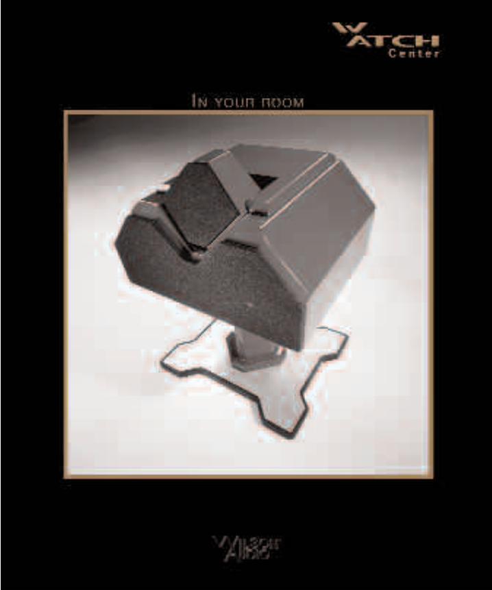
S e c t i o n 2 - I n Y o u r R o o m
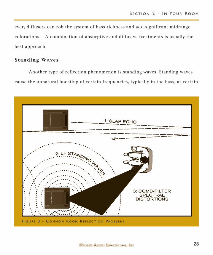
There are three commonly encountered room reflection problems, slap
echo, standing waves, and comb filter effects.
Slap Echo
Probably the most obnoxious form of reflection is called “slap echo.” In slap
echo, primarily mid-range and high frequency sounds reflect off of two parallel
hard surfaces. The sound literally bounces back and forth until it is finally dissi-
pated over time. You can test for slap echo in any room by clapping your hands
sharply in the middle of the room and listening for the characteristic sound of the
echo in the mid-range. Slap echo destroys the sound quality of a playback system
primarily in two ways:
• Adding harshness to the upper mid-range and treble through energy
time storage.
• Destroying the delicate phase relationships which help to establish
sound stage and image localization clues.
Nonparallel walls do not support slap echo, but, rather, allow the sound to
S E C T I O N 2 - I N YO U R RO O M
22
WAT C H C E N T E R C H A N N E L O W N E R ’ S M A N U A L
diffuse.
Slap echo is a common acoustical problem in the typical domestic listening
room because most of these rooms have walls of a hard, reflective nature, usually
being only occasionally interrupted by curtains or furniture. Slap echo can be con-
trolled entirely by the application of absorptive materials to hard surfaces, such as:
• Illbruck Sonex®
• Airduct board
• Cork panels
• Large ceiling to floor drapes
• Carpeting to wall surfaces
In many domestic listening environments, heavy, stuffed furnishings are
the primary structural control to slap echo. Unfortunately, their effectiveness is
not predictable. Diffusers are sometimes also used to very good subjective effect,
particularly in quite large rooms. Sound absorbent materials, such as described
above, will alter the tonal characteristic of the room by making it sound “deader,”
much heavier in bass tonal balance, less “bright and alive,” and “quieter.” These
changes usually make the room more pleasant for conversation, but sometimes ren-
der it too dull in the high frequencies to be musically involving. Diffusers, on the
other hand, tend to not change the high frequency tonal balance characteristic of
the room. Used properly, they can increase transparency. Used incorrectly, how-
23
ever, diffusers can rob the system of bass richness and add significant midrange
colorations. A combination of absorptive and diffusive treatments is usually the
best approach.
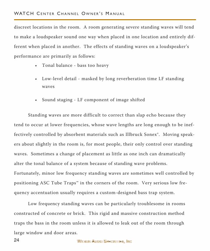
Standing Waves
Another type of reflection phenomenon is standing waves. Standing waves
cause the unnatural boosting of certain frequencies, typically in the bass, at certain
S E C T I O N 2 - I N YO U R RO O M
F I G U R E 3 - C O M M O N RO O M R E F L E C T I O N P R O B L E M S
24
discreet locations in the room. A room generating severe standing waves will tend
to make a loudspeaker sound one way when placed in one location and entirely dif-
ferent when placed in another. The effects of standing waves on a loudspeaker’s
performance are primarily as follows:
• Tonal balance - bass too heavy
• Low-level detail - masked by long reverberation time LF standing
waves
• Sound staging - LF component of image shifted
Standing waves are more difficult to correct than slap echo because they
tend to occur at lower frequencies, whose wave lengths are long enough to be inef-
fectively controlled by absorbent materials such as Illbruck Sonex®. Moving speak-
ers about slightly in the room is, for most people, their only control over standing
waves. Sometimes a change of placement as little as one inch can dramatically
alter the tonal balance of a system because of standing wave problems.
Fortunately, minor low frequency standing waves are sometimes well controlled by
positioning ASC Tube Traps™ in the corners of the room. Very serious low fre-
quency accentuation usually requires a custom-designed bass trap system.
Low frequency standing waves can be particularly troublesome in rooms
constructed of concrete or brick. This rigid and massive construction method
traps the bass in the room unless it is allowed to leak out of the room through
large window and door areas.
WAT C H C E N T E R C H A N N E L O W N E R ’ S M A N U A L
25
In general, placement of the speaker in a corner will excite the maximal
number of standing waves in a room and is to be avoided for most direct radiator,
full-range loudspeaker systems. Some benefit is achieved by placing the stereo pair
of loudspeakers very slightly asymmetrically in the listening room so that the
standing waves caused by the distance between one speaker and its adjacent walls
and floors are not the same as the standing wave frequencies excited by the dimen-
sions in the other channel.
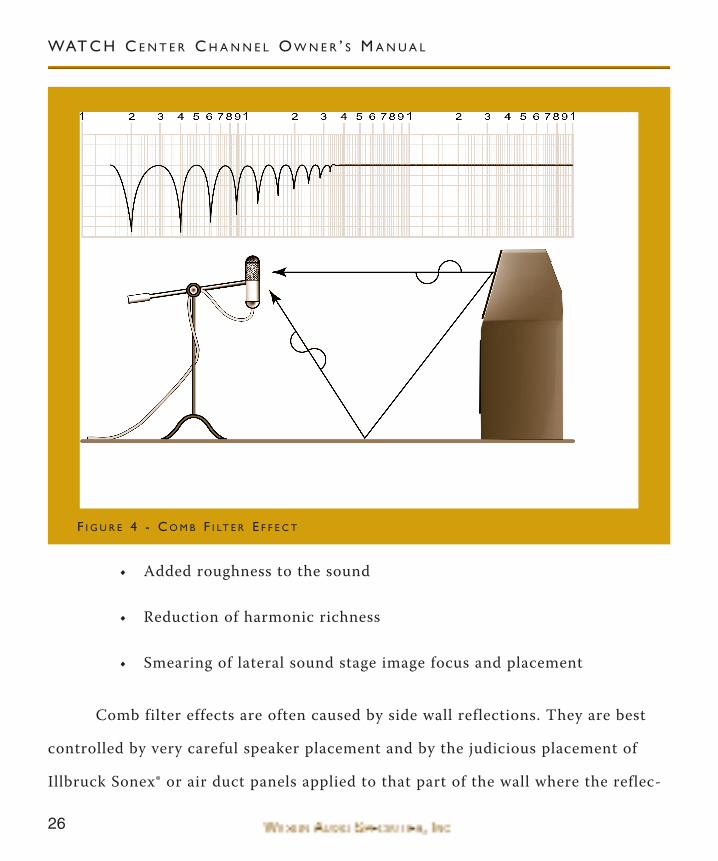
Comb Fi l ter Effect
A special type of standing wave, noticeable primarily in the midrange and
lower high frequencies, is the so-called “comb filter effect.”
Acoustical comb filtering occurs when sound from a single source, such as a
loudspeaker, is directed toward a microphone or listener at a distance. The first
sound to reach the microphone will be the direct sound, followed by delayed
reflected sound. At certain frequencies cancellation occurs because the reflected
sound lags in phase relative to the direct sound. This cancellation is most apparent
where the two are 180 degrees out of phase. There is augmentation at other fre-
quencies where the direct and the reflected sounds arrive in phase. Because it is a
function of wave length, the comb filter effect will notch out portions of the audio
spectrum at regularly spaced intervals.
The subjective effect of comb filter effects, (such as is shown in Figure 4), is
as follows:
S E C T I O N 2 - I N YO U R RO O M
26
• Added roughness to the sound
• Reduction of harmonic richness
• Smearing of lateral sound stage image focus and placement
Comb filter effects are often caused by side wall reflections. They are best
controlled by very careful speaker placement and by the judicious placement of
Illbruck Sonex® or air duct panels applied to that part of the wall where the reflec-
WAT C H C E N T E R C H A N N E L O W N E R ’ S M A N U A L
F I G U R E 4 - C O M B F I LT E R E F F E C T
27
tion occurs.
S e c t i o n 2 . 1 - R e s o n a n c e
Resonance in listening rooms is generally caused by two sources:
• The structures within the listening room
• The volume of the air itself in the listening room
Structural Resonance
Structural resonances are familiar to most people as buzzes and rattles, but
this type of resonance usually only occurs at extremely high volume levels and is
usually masked by the music. In many wood frame rooms, the most common type
of structural resonance problem is “booming” of walls and floors. You can test for
these very easily by tapping the wall with the heel of your hand or stomping on the
floor. If it is a wooden floor, this is done to detect the primary spectral center of
the resonance. To give you an idea of what the perfect wall would sound like,
imagine rapping your hand against the side of a mountain. Structural wall reso-
nances generally occur in the low to mid-bass frequencies and add tonal balance
fullness to any system played in that room. They, too, are more prominent at loud-
er levels, but their contribution to the sound of the speaker is more progressive.
Rattling windows, picture frames, lamp shades, etc., can generally be silenced with
small pieces of caulk or with blocks of felt. Short of actually adding additional lay-
S E C T I O N 2 - I N YO U R RO O M
28
ers of sheet rock or book shelves to flimsy walls, however, there is little that can be
done to eliminate wall resonances.
Air Volume Resonance
The physical dimensions and volume of air in a room will also support
standing wave modes and resonances at a frequencies determined by the size of the
room. Larger rooms will resonate at a lower frequency and have more complex
(better) modal distributions than will smaller rooms. Air volume resonances, wall
panel resonances, and low frequency standing waves, together, combine to form a
low frequency coloration in the sound. At its worst, it is a grossly exaggerated full-
ness, which tends to obscure detail and distort the natural tonal balance of the
speaker system. Occasionally, however, there is just enough resonance to give a lit-
tle added warmth to the sound, an addition some listeners prefer. Careful place-
ment of loudspeakers in the room can dramatically reduce the speakers’ destructive
interaction with low frequency modes. ASC Tube Traps™ have been found to be
effective in reducing some of these low frequency room colorations. Custom
designed and constructed bass traps, such as perforated Helmholtz resonators, pro-
vide the greatest degree of low frequency control.
WAT C H C E N T E R C H A N N E L O W N E R ’ S M A N U A L
29
S E C T I O N 2 - I N YO U R RO O M


32
WAT C H C E N T E R C H A N N E L O W N E R ’ S M A N U A L
33
S e c t i o n 3 - I n i t a l S y s t e m S e t u p
We strongly recommend that you have a Wilson Sudio dealer come to your
home and help you with the set up of the WATCH System. they have been trained
on setting up our systems to provide you with the most satisfying results. However,
if you choose to set up the system yourself, we have provided some instruction that
will allow you to achieve very good performance from the WATCH System.
If you have not read the previous section on room acoustics, do so now. It
will provide you with valuable information for determining the overall best speaker
placements and listening position. It will also allow you to fully evaluate the
acoustical qualities of your existing room and give you some ideas on how you can
improve your overall system performance.
System Setup Procedure
We recommend that you setup your multi-channel system as follows:
• Perform an acoustical analysis of your existing room.
• Find and mark the “Zones of Neutrality” for each of the speakers in
the WATCH system (more specific details are found below).
• Follow the setup procedures outlined in Section 4 and your left and
right channel owner’s manual.
• Perform the final system setup and fine tuning steps outlined in
Section 5.
S E C T I O N 3 - I N I T I A L S E T U P I N F O R M AT I O N
34
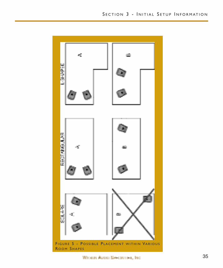
Room Shapes
Standing waves are pressure waves propagated by the interaction of sound
and opposing parallel walls. This interaction creates patterns of low and high
acoustical pressure zones that accentuate and attenuate particular frequencies.
Those frequencies are dependent on room size and dimension.
There are three basic shapes for most rooms: square, rectangular, and L-
shaped (see Figure 5).
A perfectly square room is the most difficult room in which to set up speak-
ers. By virtue of its shape, a square room is the perfect medium for building and
sustaining standing waves. These rooms heavily influence the music played by
loudspeakers, greatly diminishing the listening experience.
Long, narrow, rectangular rooms also pose their own special acoustical prob-
lems for speaker setup. They have the ability to create several standing wave
nodes, which will have different standing wave frequency exaggerations depending
on where you are sitting. Additionally, these long rooms are often quite lean in the
bass near the center of the room. Rectangular rooms are still preferred to square
rooms because, by having two sets of dissimilar length walls, standing waves are
not as strongly reinforced and will dissipate more quickly than in a square room.
In these rooms, the preferred speaker position for spatial placement and midrange
resolution would be on the longer walls. Bass response would be reinforced by
speaker placement on the short walls.
WAT C H C E N T E R C H A N N E L O W N E R ’ S M A N U A L
35
S E C T I O N 3 - I N I T I A L S E T U P I N F O R M AT I O N
F I G U R E 5 - P O S S I B L E P L A C E M E N T W I T H I N VA R I O U S
RO O M S H A P E S
36
In many cases, L-shaped rooms offer the best environment for speaker setup.
Ideally, speakers should be set up along the primary (longest) leg of the room.
They should fire from the end of the leg (short wall) toward the L, or they should
be along the longest wall. In this way, both speakers are firing the same distance to
the back wall. The asymmetry of the walls in L-shaped rooms resists the buildup
of standing waves (see Figure 5 ).
Zone of Neutral i ty
The “Zone of Neutrality” is an area in a room where the speakers will sound
most natural. This location is where the speakers interact the least with adjacent
room boundaries. It is important to have a clear working space while determining
the Zone of Neutrality.
The following is a simple method to locate the Zone of Neutrality within
your listening environment:
1. Stand against the wall BEHIND the location where you intend placing
your left and right speakers. Speaking in a moderately loud, normal
toned voice and a constant volume, project your voice out into the room.
2. As you slowly walk out from the wall, (it is helpful to have another listen-
er seated in the listening position to aid you in the evaluation), listen to
how the voice “frees up” from the added bass energy and diffuseness
imparted by the rear wall boundary.
3. When you hear the voice “free up” from this artifact, place a piece of tape
WAT C H C E N T E R C H A N N E L O W N E R ’ S M A N U A L
37
on the floor to mark this location. You will now be entering the outer
edge of the “Zone of Neutrality.” Although this can vary from room to
room, this is usually between 2 and 3 1/2 feet from the rear wall.
4. Continue to walk slowly away from the wall. After some distance, usually
one to two feet, you will hear the beginning of a new artifact - the inter-
action with the opposite wall. This will manifest itself when you hear
your voice again lose focus and it appears to reflect or echo in front of
you.
5. When you begin to hear this artifact, place a piece of tape on the floor
and mark this location. This is the inner edge of the “Zone of Neutrality.”
6. Repeat the procedure with the side walls, positioning yourself with the
zone you have established above. Continue to listen for the point in the
room where your voice loses the added bass energy from the wall behind
you, and continue until there is an obvious interaction with the opposite
wall in front of you. Do each side or speaker location individually.
The Zone of Neutrality for any room runs like a path, parallel to the walls all
around the room. Adjacent to very large windows and open doors, the outer edge
of the Zone of Neutrality moves closer to the wall and becomes wider. If you
extend the inner and outer boundaries of the Zone for the side walls and the front
wall (behind the speakers), they will intersect. You will now have two rectangles on
the floor on either side of the room, which is your Zone of Neutrality for each
channel.
S E C T I O N 3 - I N I T I A L S E T U P I N F O R M AT I O N
38
S e c t i o n 3 . 1 - C h o o s i n g a L i s t e n i n g P o s i t i o n
Decide where you want your listening position to be. Please remember that
your WATCH System can fill most rooms with beautiful sound. However, for the
PDC advantage, we want to ensure that you get all the benefits possible with the
propagation delay adjustment features that are built into this design. Listening
positions that are too close to a boundary will deteriorate the overall system per-
formance.
Speaker Placement vs . Listening Posit ion
The location of your listening position is as important as the careful setup
placement of your speakers in your room. The listening position ideally should be
no more than 1.1 to 1.25 times the distance between the left and right channel
tweeters on each speaker. Therefore, in a long rectangular room of 12’ x 18’, if the
speaker tweeters are going to be 9’ apart, you should be sitting 9’11’’ to 11’3’’ from
the speaker. This would be about halfway down the long axis of the room.
Experiment carefully for best low frequency response.
Some people place the speakers on one end and sit at the other end of the
room. Needless to say, this will not yield the finest sound. Carefully consider your
listening position for optimal performance. Our experience has shown that any lis-
tening position that places your head closer than 14” to a room boundary will
diminish the sonic results of your listening.
WAT C H C E N T E R C H A N N E L O W N E R ’ S M A N U A L
39
Speaker Orientat ion
Speaker placement and orientation are two of the most important considera-
tions in obtaining superior sound. The first thing you need to do is minimize the
influence of the side walls on the sound of your system. Speakers placed too close
to the side walls will suffer from a strong primary reflection. This can cause out of
phase cancellations, or comb filtering, which will cancel some frequencies and
change the tonal balance of the music. A good place to start is with the speakers
about 18” from each wall and, if you need to move them relative to the side wall,
move them away from the wall, not closer.
Another important aspect of speaker placement is how far to place the
speakers from the wall behind them. The closer to the back wall, the more pro-
nounced the low bass energy and centering of the image will be. However, this
comes at a definite reduction in stage size and bloom as well as a deterioration of
upper bass quality. You must find the proper balance of these two factors.
Remember, if you are partial to bass response or air and bloom, do not overcom-
pensate your adjustments to maximize their effects. Overbalanced systems are
sometimes pleasing in the short term, but long term satisfaction is always achieved
through proper balance.
Center Channel
After determining the general area for the left and right channel, determine
the best place for your WATCH Center Channel. The following center channel
S E C T I O N 3 - I N I T I A L S E T U P I N F O R M AT I O N
40
configurations are possible:
• Set on the floor with speaker angled up towards the listener.
• Mounted on stand with no rotation.
• Mounted on stand with longer spikes in the front of stand and shorter
spikes in the back allowing the stand and speaker to be rotated up
toward the listener.
• Mounted above TV on a custom made bracket.
• Mounted upside down on ceiling with speaker angled down towardsthe
listener.
Except for the ceiling mounted option, all of the above arrangements will
allow for some fine tuning of speaker placement once the entire system is set up. If
you are mounting the speaker to the ceiling, be sure to choose the location careful-
ly as you will not be able to move the WATCH Center Channel once it is bolted to
the ceiling. A poor placement will lower overall system integration and perform-
ance. As a general rule, the distance from the main left and right tweeters to the
listening position should be the same as the distance from the center channel
tweeter to the listening position. This allows the sound provided by each speaker
to arrive at the ear at the same time. The phase delay correction will be made via
the sliding tweeter module on the WATCH Center Channel.
Our testing has shown that a floor or stand mounted center channel inte-
WAT C H C E N T E R C H A N N E L O W N E R ’ S M A N U A L
41
grates best when placed centered between the left and right speaker and either
aligned horizontally with the front inner edge of the left and right speakers or
slightly behind the front inner edge. You will want to experiment with the center
channel distances and find the location that offers the smoothest left, right, and
WATCH Center Channel integration. We will step you through this process in
Section 5.
Surround Channel
Wilson Audio has done everything possible to eliminate the boundary inter-
actions caused by mounting a speaker onto the wall. The mounting bracket allows
for significant improvements in detail, speed, and clarity. The WATCH Surround
channels will perform well in almost any location they are placed. The mounting
bracket and the careful design of the WATCH Surround have eliminated most of
the sonic problems encountered when placing a standard speaker too close to a
boundary. Nevertheless, we have performed extensive testing on the WATCH
Surround and found that significant improvement on speaker linearity and integra-
tion can be achieved by careful selection of the surround channel mounting loca-
tion.
We realize that the location of the WATCH Surround channel is generally
set by the architecture of the room. However, if you have some flexibility in the
wall mounting location, we suggest that you perform a zone of neutrality test and
find the area along the wall where your voice sounds the most natural and has the
S E C T I O N 3 - I N I T I A L S E T U P I N F O R M AT I O N
42
least amount of reflections or standing waves. Be sure to listen for room modes and
frequency response peaks or dips.
WATCH Dog
The WATCH Dog will perform very well in any location in the room. In
general, the closer you place theWATCH Dog to a wall or corner, the greater the
augmentation of the bass. However, the increase in bass comes at a cost of per-
ceived speed, dynamics, and bass clarity. We recommend that you experiment with
the placement of theWATCH Dog to find a balance of the above mentioned items.
S e c t i o n 3 . 2 - I n i t i a l S e t u p S u m m a r y
Ideally, the speakers should not be positioned too far from the listener if
maximum resolution of low level detail is required (near-field monitoring). If pos-
sible, the speakers should be positioned out into the room, slightly asymmetrically
away from side and rear walls. The speakers should be toed-in toward the listener,
It is preferable that the listener, at his seated position, can barely see the surface of
the inner side-panel of the left and right speakers as he faces the speaker. It is rec-
ommended that a distance of 2-3 feet, and possibly more, be maintained between
the left and right speakers and the rear walls. A distance of at least 1 1/2 feet
should be maintained between the front panel of the left and right speakers and
reflective side walls. Use of sound absorbent materials may reduce the space
requirement somewhat. Experiment for each room.
WAT C H C E N T E R C H A N N E L O W N E R ’ S M A N U A L
43
Be sure to place the WATCH Center Channel even with or slightly behind
the front inner edge of the left and right speakers.
The WATCH Surround channel should be mounted on the wall in a location
that has the least amount of reflections and standing waves. The location should
have a natural sound if you stand next to it and project your voice into the room.
The WATCH Dog has a great degree of flexibility in its placement. The final
location will be determined by aesthetics and user taste, balancing the quality vers-
es the quantity of bass.
S E C T I O N 3 - I N I T I A L S E T U P I N F O R M AT I O N


46
WAT C H C E N T E R C H A N N E L O W N E R ’ S M A N U A L
47
Note: Before setting up the WATCH Center Channel study carefully the previ-ous sections on room acoustics and initial setup information. They providevaluable information on determining the ideal room locations for your speak-ers.
S e c t i o n 4 - W A T C H C e n t e r C h a n n e l S e t u p
You will need the following items:
• Supplied hardware kit
• Tape measure
• Known listening position
Note: The WATCH Center Channel is shipped with four set screws, which areinserted into the threaded holes on the bottom of the Center Channel. If youare simply placing the Center Channel on a shelf and are not planning on fol-lowing the setup procedure, leave these set screws in place. If you are planningon mounting the Center Channel to a stand or using any provided spikes toangle the Center Channel towards the listening position, these four set screwswill need to be removed. Remove the set screws as follows:
1. Carefully set the speaker onto its side.
2. Using the provided 3/16” angled Allen wrench, unscrew the set screws.
Note: You should have two 1 1/2” set screws and two 2” set screws. Save theseset screws as you will need them if you plan on adding rotation towards thelistening position.
3. Proceed to the installation instructions provided.
S E C T I O N 4 - WAT C H C E N T E R C H A N N E L S E T U P
48
Setup Procedure
1. Gently slide the WATCH Center Channel out of the crate. Remove the
plastic outer bag by tilting the Center channel over on one side and open-
ing the bag at the base of the Center channel. Remove the bag.
Note: Do not cut the bag off of the Center channel. You may mark the cabinetor damage a driving element. Additionally, you will need this bag, if you needto repackage the Center channel. Save your shipping crates and all packingmaterials. They are specifically designed to prevent harm from coming to yourCenter channel.
2. Move the Center channel into the desired location.
Note: Be careful not to touch the driving elements when you are moving yourWATCH Center channel!
Center Channel Spike Assembly
The WATCH Center channel comes with two sets of spikes with a diode and
spacers, and two sets of spikes with only the spike and nut. This will allow the
speaker to be tilted to a variety of angles. These spikes provide acoustical isolation
as well as optimal height placement for your speakers. There are three ways of
assembling the spikes (without spacers, with one spacer, or with two spacers), and
your choice will depend on the location of the Center channel and personal tastes.
The spacers are provided to allow for the rotation of the WATCH Center towards
the listener. If the speaker is floor mounted, it will be tilted upward so the drivers
WAT C H C E N T E R C H A N N E L O W N E R ’ S M A N U A L
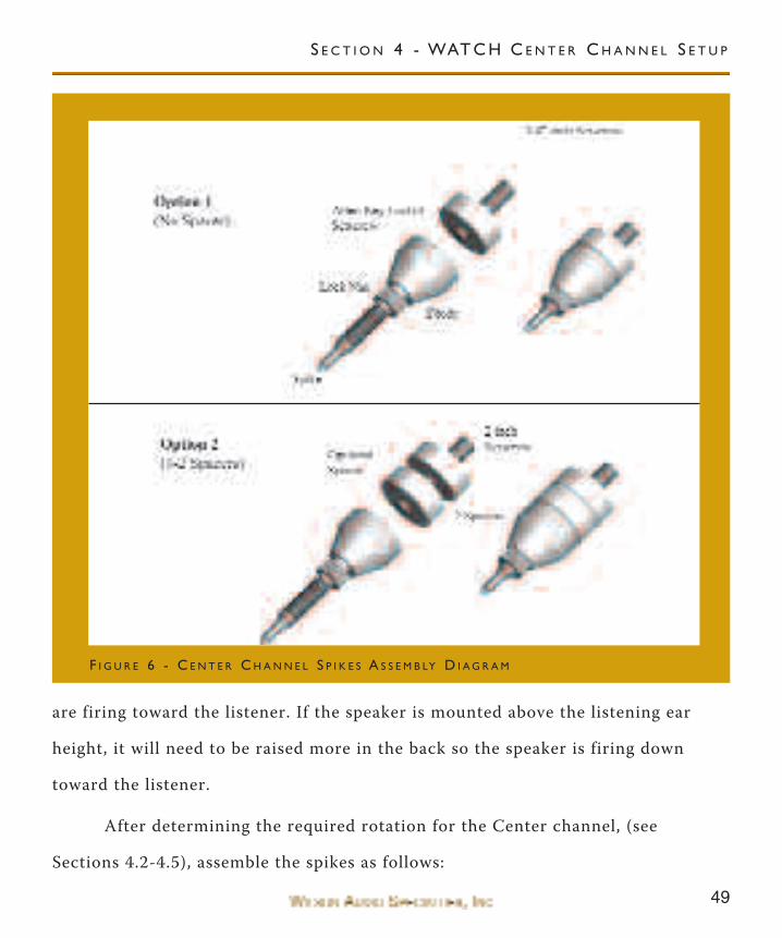
49
are firing toward the listener. If the speaker is mounted above the listening ear
height, it will need to be raised more in the back so the speaker is firing down
toward the listener.
After determining the required rotation for the Center channel, (see
Sections 4.2-4.5), assemble the spikes as follows:
F I G U R E 6 - C E N T E R C H A N N E L S P I K E S A S S E M B LY D I A G R A M
S E C T I O N 4 - WAT C H C E N T E R C H A N N E L S E T U P
50
1. Insert either the short or the long threaded bolt, depending on the
desired height (see Figure 6) as far as it will go into the hole in the bot-
tom of the Center channel. Make sure the Allen key end is accessible.
2. If required, place the corresponding number of spacer discs over the bolt.
3. Screw the acoustical diode onto the bolt until it is roughly half way into
the diode.
4. Screw the spike (with nut) all the way in until it just touches the bolt. Do
not tighten the nut at this time.
5. Repeat steps 1 through 4 with the other spikes.
S e c t i o n 4 . 1 - M e a s u r e d L i s t e n i n g P o s i t i o n
Pulse alignment accuracy of the Center channel has been established and
verified at Wilson Audio’s R&D laboratory. The tables used in this section are a
result of this testing.
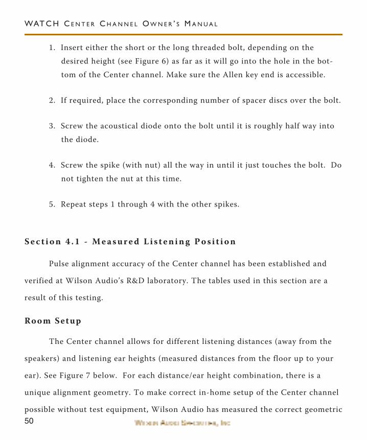
Room Setup
The Center channel allows for different listening distances (away from the
speakers) and listening ear heights (measured distances from the floor up to your
ear). See Figure 7 below. For each distance/ear height combination, there is a
unique alignment geometry. To make correct in-home setup of the Center channel
possible without test equipment, Wilson Audio has measured the correct geometric
WAT C H C E N T E R C H A N N E L O W N E R ’ S M A N U A L
51
PDC (phase delay correction) alignment for different distance/ear height combina-
tions. This information is provided in Section 9. By measuring the ear height and
the distance from the speaker to the listening position, you will be able to align the
system for your listening position.
Center Channel Configurations
The WATCH Center channel has been designed to accommodate most any
mounting location. These locations, in order of preference, are as follows:
1. Center Channel on Stand (Recommended Location)
2. Center Channel on Floor
3. Center Channel on Custom Stand or Shelf
4. Center Channel on Ceiling
The Center channel crossover has been optimized for use with the Center
stand. This is the preferred location. When you mount the Center channel in most
F I G U R E 7 - M E A S U R E D L I S T E N I N G D I S TA N C E A N D E A R H E I G H T
M E A S U R E L I S T E N I N G D I S TA N C E
M E A S U R E E A R H E I G H TF R O M T H E F L O O R
S E C T I O N 4 - WAT C H C E N T E R C H A N N E L S E T U P
52
other locations, you will begin to see more boundary interactions, which may alter
the performance of the speaker. Nevertheless, the WATCH Center Channel will
certainly out-perform any other center channel placed in a given location.
Placing the Center channel in any location other than on the Wilson Audio
WATCH Center stand will require the WATCH Center channel to be rotated
toward the listening position. This will allow the center channel to take advantage
of the phase delay correction technology (PDC). Simply placing the Center on top
of the TV or any other location, without following the directions below, will hinder
the performance of the WATCH Center channel. With the correct PDC you will
find the vocals and dialogue more realistic and satisfying. As with any component
in your system that offers increased resolution and detail, a careful setup is
required.
There are four different setup procedures depending on your Center channel
location. The possible Center channel configurations are as follows:
• Section 4.2 - Center Channel on Floor
• Section 4.3 - Center Channel on Stand
• Section 4.4 - Center Channel on Custom Stand or Shelf
• Section 4.5 - Center Channel on Ceiling
For detailed setup instructions, please proceed to the indicated section for
your particular installation.
WAT C H C E N T E R C H A N N E L O W N E R ’ S M A N U A L
53
S e c t i o n 4 . 2 - C e n t e r C h a n n e l o n F l o o r
The floor mounted Center channel must be rotated up toward the listening
position. This is done by using a taller spike in the front than in the back of the
speaker (see Figure 8). The default rotation is set by using a combination of a
spike, a lock nut, and an acoustical diode. If required, additional rotation can be
achieved by using the provided 1/2” spacers between the diode and the bottom of
the cabinet (see Figure 6, page 49). The amount of rotation depends on your lis-
tening position.
Set the rotation as follows:
D I O D E , S P I K E ,A N D N U T
S P I K E A N DN U T O N LY
S PA C E R S( U S E O N LY I F I N D I -C AT E D I N TA B L E )
F I G U R E 8 - I N S TA L L I N G T H E S P I K E S
S E C T I O N 4 - WAT C H C E N T E R C H A N N E L S E T U P
54
1. Using provided 3/16” Allen wrench, remove the 4 setscrews from the bot-
tom of the Center channel. Keep these as they are the setscrews needed
to assemble your spikes.
2. Turn to Section 9, page 107. Locate your listening position on the table.
3. Assemble the front spikes with the listed diode/spacer combination.
4. Install the spikes as shown in Figure 8 above.
Note: The material used for the bottom of the WATCH Center channel is ahigh density composite. This material is easily cross-threaded when installingthe spikes. Be careful that the spike thread is engaging properly into the bot-tom of the enclosure.
5. Carefully lift the Center channel into the desired location and set it
down.
Note: Four small brass disks have been provided for use as spike pads. Placethese under the spikes to protect the finish of your floors.
6. Turn to section 4.6 for final assembly instructions.
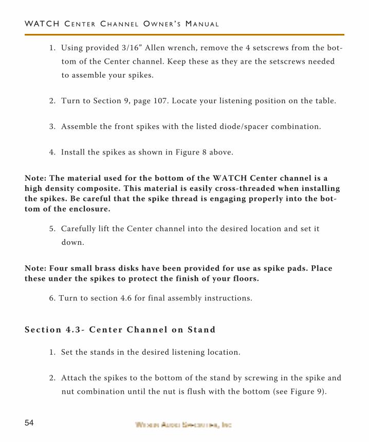
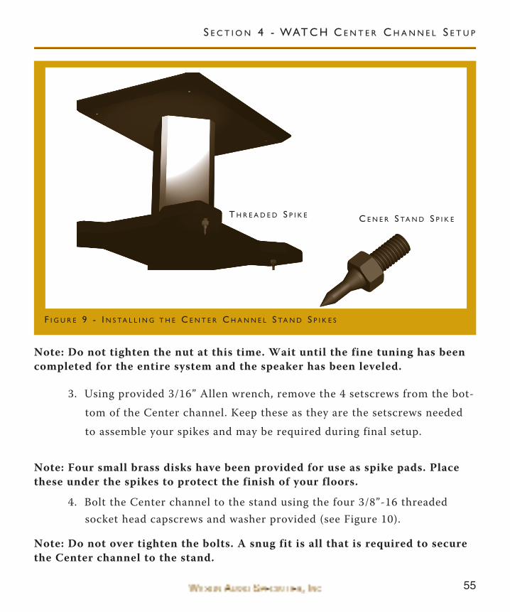
S e c t i o n 4 . 3 - C e n t e r C h a n n e l o n S t a n d
1. Set the stands in the desired listening location.
2. Attach the spikes to the bottom of the stand by screwing in the spike and
nut combination until the nut is flush with the bottom (see Figure 9).
WAT C H C E N T E R C H A N N E L O W N E R ’ S M A N U A L
55
Note: Do not tighten the nut at this time. Wait until the fine tuning has beencompleted for the entire system and the speaker has been leveled.
3. Using provided 3/16” Allen wrench, remove the 4 setscrews from the bot-
tom of the Center channel. Keep these as they are the setscrews needed
to assemble your spikes and may be required during final setup.
Note: Four small brass disks have been provided for use as spike pads. Placethese under the spikes to protect the finish of your floors.
4. Bolt the Center channel to the stand using the four 3/8”-16 threadedsocket head capscrews and washer provided (see Figure 10).
Note: Do not over tighten the bolts. A snug fit is all that is required to securethe Center channel to the stand.
T H R E A D E D S P I K E C E N E R S TA N D S P I K E
F I G U R E 9 - I N S TA L L I N G T H E C E N T E R C H A N N E L S TA N D S P I K E S
S E C T I O N 4 - WAT C H C E N T E R C H A N N E L S E T U P

5. Turn to section 4.6 for final assembly instructions.
S e c t i o n 4 . 4 - C e n t e r C h a n n e l o n C u s t o m S t a n d o r S h e l f
The Center Channel is a shielded speaker, and therefore, could be placed
directly on top of a television. However, this is not recommended due to the weight
of the speaker. In time, damage may occur to your television. We recommend that
you have a custom shelf built that allows the WATCH Center to be bolted securely
WAT C H C E N T E R C H A N N E L O W N E R ’ S M A N U A L
F I G U R E 1 0 - B O LT I N G T H E C E N T E R C H A N N E L T O T H E S TA N D
A N C H O R B O LT
57
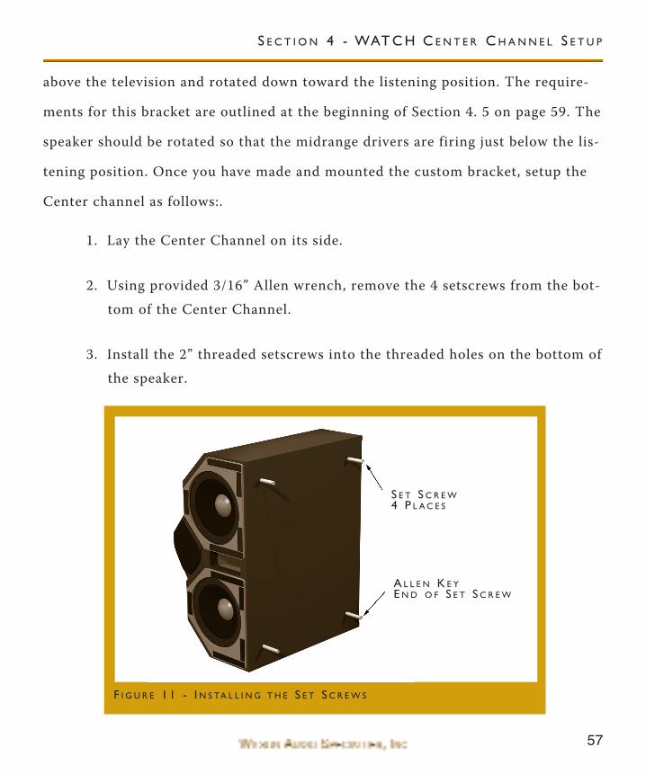
above the television and rotated down toward the listening position. The require-
ments for this bracket are outlined at the beginning of Section 4. 5 on page 59. The
speaker should be rotated so that the midrange drivers are firing just below the lis-
tening position. Once you have made and mounted the custom bracket, setup the
Center channel as follows:.
1. Lay the Center Channel on its side.
2. Using provided 3/16” Allen wrench, remove the 4 setscrews from the bot-
tom of the Center Channel.
3. Install the 2” threaded setscrews into the threaded holes on the bottom of
the speaker.
S E T S C R E W4 P L A C E S
A L L E N K E YE N D O F S E T S C R E W
F I G U R E 1 1 - I N S TA L L I N G T H E S E T S C R E W S
S E C T I O N 4 - WAT C H C E N T E R C H A N N E L S E T U P
58
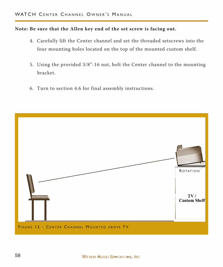
Note: Be sure that the Allen key end of the set screw is facing out.
4. Carefully lift the Center channel and set the threaded setscrews into the
four mounting holes located on the top of the mounted custom shelf.
5. Using the provided 3/8”-16 nut, bolt the Center channel to the mounting
bracket.
6. Turn to section 4.6 for final assembly instructions.
WAT C H C E N T E R C H A N N E L O W N E R ’ S M A N U A L
RO TAT I O N
F I G U R E 1 2 - C E N T E R C H A N N E L M O U N T E D A B O V E T V
59
S E C T I O N 4 - WAT C H C E N T E R C H A N N E L S E T U P
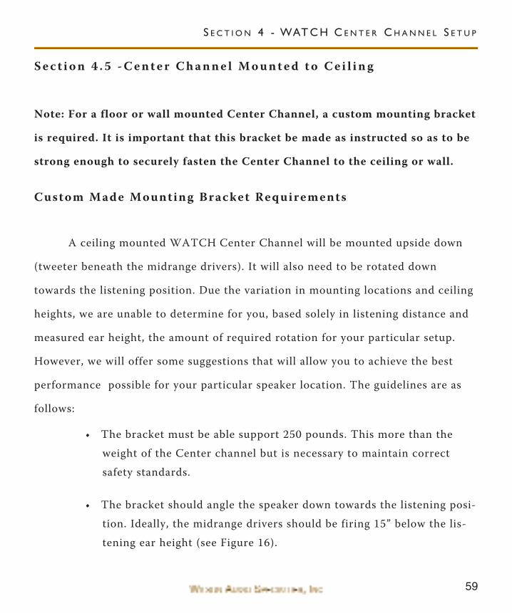
S e c t i o n 4 . 5 - C e n t e r C h a n n e l M o u n t e d t o C e i l i n g
Note: For a floor or wall mounted Center Channel, a custom mounting bracket
is required. It is important that this bracket be made as instructed so as to be
strong enough to securely fasten the Center Channel to the ceiling or wall.
Custom Made Mounting Bracket Requirements
A ceiling mounted WATCH Center Channel will be mounted upside down
(tweeter beneath the midrange drivers). It will also need to be rotated down
towards the listening position. Due the variation in mounting locations and ceiling
heights, we are unable to determine for you, based solely in listening distance and
measured ear height, the amount of required rotation for your particular setup.
However, we will offer some suggestions that will allow you to achieve the best
performance possible for your particular speaker location. The guidelines are as
follows:
• The bracket must be able support 250 pounds. This more than the
weight of the Center channel but is necessary to maintain correct
safety standards.
• The bracket should angle the speaker down towards the listening posi-
tion. Ideally, the midrange drivers should be firing 15” below the lis-
tening ear height (see Figure 16).
60
WAT C H C E N T E R C H A N N E L O W N E R ’ S M A N U A L
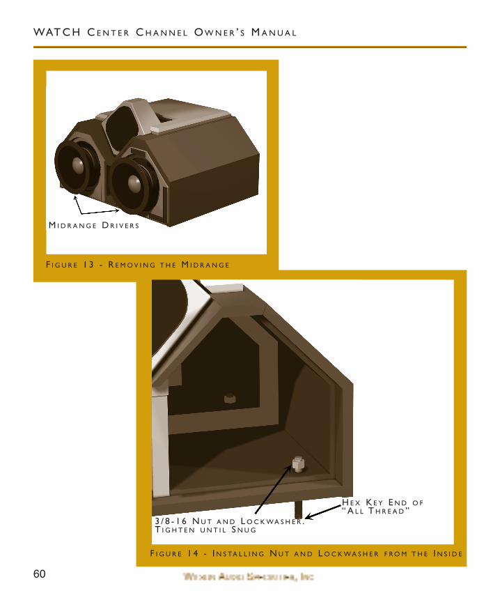
M I D R A N G E D R I V E R S
H E X K E Y E N D O F“ A L L T H R E A D ”
3 / 8 - 1 6 N U T A N D L O C K WA S H E R .T I G H T E N U N T I L S N U G
F I G U R E 1 4 - I N S TA L L I N G N U T A N D L O C K WA S H E R F R O M T H E I N S I D E
F I G U R E 1 3 - R E M O V I N G T H E M I D R A N G E
61
S E C T I O N 4 - WAT C H C E N T E R C H A N N E L S E T U P
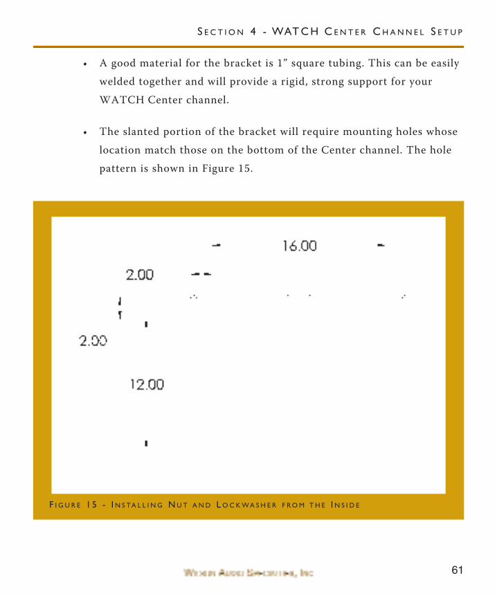
• A good material for the bracket is 1” square tubing. This can be easily
welded together and will provide a rigid, strong support for your
WATCH Center channel.
• The slanted portion of the bracket will require mounting holes whose
location match those on the bottom of the Center channel. The hole
pattern is shown in Figure 15.
F I G U R E 1 5 - I N S TA L L I N G N U T A N D L O C K WA S H E R F R O M T H E I N S I D E
62
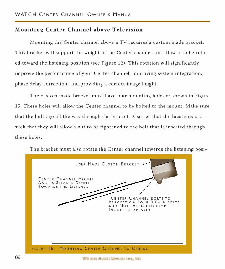
Mounting Center Channel above Televis ion
Mounting the Center channel above a TV requires a custom made bracket.
This bracket will support the weight of the Center channel and allow it to be rotat-
ed toward the listening position (see Figure 12). This rotation will significantly
improve the performance of your Center channel, improving system integration,
phase delay correction, and providing a correct image height.
The custom made bracket must have four mounting holes as shown in Figure
15. These holes will allow the Center channel to be bolted to the mount. Make sure
that the holes go all the way through the bracket. Also see that the locations are
such that they will allow a nut to be tightened to the bolt that is inserted through
these holes.
The bracket must also rotate the Center channel towards the listening posi-
WAT C H C E N T E R C H A N N E L O W N E R ’ S M A N U A L
U S E R M A D E C U S T O M B R A C K E T
C E N T E R C H A N N E L M O U N TA N G L E S S P E A K E R D O W NTO WA R D S T H E L I S T E N E R
C E N T E R C H A N N E L B O LT S T OB R A C K E T V I A F O U R 3 / 8 - 1 6 B O LT SA N D N U T S AT TA C H E D F R O MI N S I D E T H E S P E A K E R
F I G U R E 1 6 - M O U N T I N G C E N T E R C H A N N E L T O C E I L I N G
63
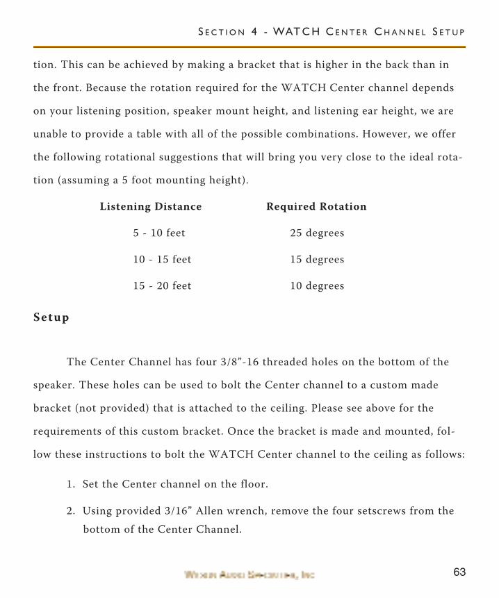
tion. This can be achieved by making a bracket that is higher in the back than in
the front. Because the rotation required for the WATCH Center channel depends
on your listening position, speaker mount height, and listening ear height, we are
unable to provide a table with all of the possible combinations. However, we offer
the following rotational suggestions that will bring you very close to the ideal rota-
tion (assuming a 5 foot mounting height).
Listening Distance Required Rotation
5 - 10 feet 25 degrees
10 - 15 feet 15 degrees
15 - 20 feet 10 degrees
Setup
The Center Channel has four 3/8”-16 threaded holes on the bottom of the
speaker. These holes can be used to bolt the Center channel to a custom made
bracket (not provided) that is attached to the ceiling. Please see above for the
requirements of this custom bracket. Once the bracket is made and mounted, fol-
low these instructions to bolt the WATCH Center channel to the ceiling as follows:
1. Set the Center channel on the floor.
2. Using provided 3/16” Allen wrench, remove the four setscrews from the
bottom of the Center Channel.
S E C T I O N 4 - WAT C H C E N T E R C H A N N E L S E T U P
64
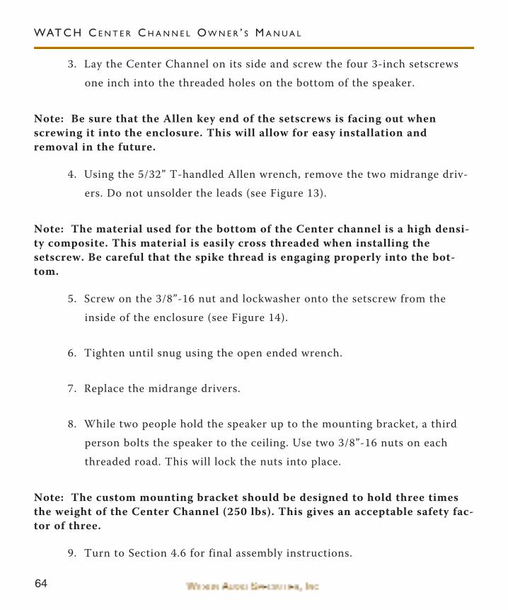
3. Lay the Center Channel on its side and screw the four 3-inch setscrews
one inch into the threaded holes on the bottom of the speaker.
Note: Be sure that the Allen key end of the setscrews is facing out whenscrewing it into the enclosure. This will allow for easy installation andremoval in the future.
4. Using the 5/32” T-handled Allen wrench, remove the two midrange driv-
ers. Do not unsolder the leads (see Figure 13).
Note: The material used for the bottom of the Center channel is a high densi-ty composite. This material is easily cross threaded when installing thesetscrew. Be careful that the spike thread is engaging properly into the bot-tom.
5. Screw on the 3/8”-16 nut and lockwasher onto the setscrew from the
inside of the enclosure (see Figure 14).
6. Tighten until snug using the open ended wrench.
7. Replace the midrange drivers.
8. While two people hold the speaker up to the mounting bracket, a third
person bolts the speaker to the ceiling. Use two 3/8”-16 nuts on each
threaded road. This will lock the nuts into place.
Note: The custom mounting bracket should be designed to hold three timesthe weight of the Center Channel (250 lbs). This gives an acceptable safety fac-tor of three.
9. Turn to Section 4.6 for final assembly instructions.
WAT C H C E N T E R C H A N N E L O W N E R ’ S M A N U A L
65
S e c t i o n 4 . 6 - C e n t e r C h a n n e l F i n a l S e t u p
The final setup work needed before fine tuning and other speaker setup is
performed as follows:
• Set the Phase Delay Correction on the tweeter assembly.
• Connect the speaker cables from the amplifier.
Phase Delay Correct ion - Stand or Floor Mounted
The phase delay correction is one of the most important elements of the
setup. There are two methods for setting the PDC: one for floor and stand mount-
ed Center channel and one for ceiling or any other custom location. Set up the
PDC as follows:
1. Find your measured listening distance and ear height.
2. In Section 9, locate the table that corresponds to your Center channel
location and front spike combination (i.e. floor mounted center channel
with spike, nut, diode and one spacer).
Note: There is a unique PDC setting for each Center channel location andfront spike combination. Be sure you are reading from the correct table.
3. Read from the table the required offset (1-13).
S E C T I O N 4 - WAT C H C E N T E R C H A N N E L S E T U P
66
4. Using a 3/16” Allen wrench, loosen the 1/4”-20 socket head on tweeter
assembly (see Figure 17 below).
5. Slide the tweeter until the lock down bolt is centered above the alignment
mark on the tweeter mounting bracket.
6. Retighten the socket head capscrews until snug.
Note: When loosening or tightening the screws, be careful that you do notdamage the painted finish.
Phase Delay Correct ion - Cei l ing or Other Custom Location
Because of the large number of unique combinations for your location, we
are unable to provide the exact alignment setting for you. If you have followed the
instructions closely up to this point, you will be able to set the PDC by experiment.
This is done as follows:
• Unhook all the speakers except the Center Channel.
• Using a 3/16” Allen wrench, loosen the 1/4”-20 socket head bolts that
hold the tweeter in place.
• Play a sound track that has female vocal.
• Sit in your listening location and have someone slowly slide the tweet-
er forward and backwards. Listen for the location that the female
vocal is free from any chest or nasal sound. The vocals will be clean
WAT C H C E N T E R C H A N N E L O W N E R ’ S M A N U A L
67
and clear, free from any veiling of the sound. This is the correct align-
ment position.
• Lock down the tweeter in this position.
S E C T I O N 4 - WAT C H C E N T E R C H A N N E L S E T U P
1 / 4 - 2 0 S O C K E T H E A DC A P S C R E W
T W E E T E R S L I D E SB A C K A N D F O RT H
F I G U R E 1 7 - S E T T I N G T H E P D C
68
S e c t i o n 4 . 7 - C o n n e c t i n g S p e a k e r t o A m p l i f i e r
Speaker Cables
The very high current input terminals located on the rear of your Center
channel loudspeaker are color coded with a small plastic plug so that RED corre-
sponds to positive and black to negative, common, or ground on the amplifier out-
put. Be sure to connect the loudspeakers in phase with each other. We recom-
mend the use of the very highest quality loudspeaker cables, particularly those
designed for high frequency propagation correction and phase linearity. Beware of
“zip cord” type speaker cables which will smear the sound and limit their effective
bandwidth. Also, do not use braided litz type loudspeaker cables as they will cause
an unnatural brightness to the sound, compromise sound staging performance, and
may cause instability, oscillation, and damage in wide bandwidth solid state ampli-
fiers.
Spade Lugs
The spade lugs of some of the high quality cables often used with the Center
channel are angled to reduce pressures on the cable during installation. Avoid the
instinct to push the cable’s spade lug ends all the way into the Center channel’s
WAT C H C E N T E R C H A N N E L O W N E R ’ S M A N U A L
69
connectors (See Figure 18). Partial insertion of these angled spade lugs will actu-
ally improve the reliability of the connection. Flat lugs may be fully inserted into
connectors before tightening.
Connection of the Center Channel to the Power Ampli f ier
1. Turn off the power amplifier(s) and remove the AC power cord from the
wall outlet.
2. Lay out the speaker cables before hooking them up to the WATCH
Center channel. Make sure that there are no kinks, twists, or right-
S E C T I O N 4 - WAT C H C E N T E R C H A N N E L S E T U P
F I G U R E 1 8 - S PA D E L U G AT TA C H M E N T
70
angled bends in the cable. If you need to turn corners, attempt to use a
gradual curve as opposed to a severe right-angled bend.
3. Connect the negative (normally black) end of the speaker cable to the
high current speaker binding post with the engraved “-” above it ( see
Figure 19).
Note: Do not over tighten the binding posts. Over tightening can cause theposts to break off.
4. Connect the positive (normally red) end of the speaker cable to the high
current speaker binding post with the engraved “+” above it.
5. Plug your amplifier(s) AC power cord into the wall outlet.
Note: Always attempt to keep your pair of speaker cables the same length.This will ensure that the signals arrive at each speaker in the proper timeframe, by traveling the same distance to each speaker.
Center Channel Setup Completed
This completes the initial setup of your WATCH Center channel. Final sys-
tem tuning and voicing should be performed as outlined in Section 5. Section 5 will
evaluate your entire speaker setup and allow you to make small modifications in
speaker rotation and location that will greatly improve the performance of your
multi-channel audio or home theater system.
WAT C H C E N T E R C H A N N E L O W N E R ’ S M A N U A L
71
F I G U R E 1 9 - C E N T E R C H A N N E L C A B L E C O N N E C T I O N
M A I N I N B I N D I N G P O S T S
R E S I S T O R A C C E S S
S E C T I O N 4 - WAT C H C E N T E R C H A N N E L S E T U P


74
WAT C H C E N T E R C H A N N E L O W N E R ’ S M A N U A L
75
S e c t i o n 5 - F i n a l S y s t e m T u n i n g a n d V o i c i n g
This loudspeaker placement method was developed by David A. Wilson, for
Wilson Audio Specialties. The purpose of this method is to find optimum loud-
speaker location in any given room within one hour. Participating in numerous
audio/multi-channel/home theater shows with very different and difficult acoustic
environments necessitated this procedure. Currently, all Wilson Audio dealers
employ this setup procedure for their customers in order to quickly and pre-
dictably achieve the best performance from their systems (This procedure can be
used successfully with ANY moving coil speaker system).
Proper system calibration is the most important step in the setup of your
multi-channel/home theater system. The WATCH system offers increased resolu-
tion and overall system performance. This increased resolution allows you to fine
tune your system, thus increasing overall performance, more than any other system
available.
Fine tuning and “voicing” generally involve only small changes in location
and rotation (or toe) of your multi-channel system. With proper calibration you
will find that changes as small as one inch will have an impact on the performance
of your system. The following sections will step you through this fine tuning
process. The setup will be done as follows:
S E C T I O N 5 - F I N A L S Y S T E M T U N I N G A N D V O I C I N G
76
• Set up of Left and Right Channels, with all other speakers discon-
nected.
• Add the Center Channel.
• Add the Surround Channels.
• Add the Subwoofer.
Adding one speaker at a time will allow you to easily evaluate the integration
with the system and make the necessary adjustments to fine tune the setup.
S e c t i o n 5 . 1 - L e f t a n d R i g h t C h a n n e l s
Determining Front to Back Distance
The proper setup of the left and right channels is crucial for optimum sys-
tem performance. If these speakers are not set up correctly, the entire system will
suffer from poor integration. Please follow these steps carefully:
• Place the speaker in an appropriate location relative to your screen
and listening area. Make certain to remove the grilles and spikes.
• Toe-in the speakers so that you can just barely see the inside edge
when seated in the primary listening position.
• Using removable masking tape, graph off the floor so that you can
accurately move both speakers forward and backward in 1/2 inch
increments.
WAT C H C E N T E R C H A N N E L O W N E R ’ S M A N U A L
77
• Place your multi-channel processor into stereo mode.
• Using a piece of full range music (dynamic with a lot of low frequency
information) played at a moderately high level, take notes on the
sound quality. Pay specific attention to upper and lower bass quality,
dynamic contrasts, image height, and focus.
• Move the speakers back or forward in one inch increments and then
1/2 inch increments.
Note: Moving the speakers BACK will generally increase low bass, sharpenfocus, lower image height, and increase dynamics up to the point where you gotoo far. In this case the sound will start to lose these qualities in addition tobecoming boomy and slow sounding. Moving the speakers FORWARD willincrease air and bloom, raise image height, and generally increase the sense ofspace. Moving too far forward will cause the soundstage to become unnatural-ly high with a lack of focus, dynamics, and low end extension.
• Find the front to back location where the bass is tight, dynamics are
correct, and image is well focused, and you find the best sound stag-
ing.
• Mark this as your final front to back location.
Determining Side to Side Distance
The distance the speakers are from the side walls is very important. This dis-
tance determines the amount of comb filtering you will hear. In effect, you are
“tuning” the comb filter interaction between the speaker and the wall. Perform the
side to side analysis as follows:
S E C T I O N 5 - F I N A L S Y S T E M T U N I N G A N D V O I C I N G
78
• Place a piece of tape on the floor parallel to the front edge of the
speaker and again mark off 1/2 inch increments side to side.
• Using only one channel/speaker at a time, you will now determine the
optimum position with regard to the side walls.
Note: A high quality, solo piano recording works well for this step.
• While the music is playing, slowly move the speakers left or right one
inch then 1/2 inch at a time until you achieve the best harmonic
integrity.
You should not need to move the speaker any more than one inch left or
right from the original location. Do this independently for each channel. What
you will hear when the speaker moves into the correct location is a reduction of
hardness and muddied harmonics from the piano.
Note: If you continue moving the speaker past this point, you will begin tohear again this fatiguing artifact.
When you have determined the optimum location for each speaker, mark it
carefully, and make certain the toe-in is correct. When installing the spikes, the
speakers may shift slightly, but you can move them precisely back to the correct
location again using your tape markers.
S e c t i o n 5 . 2 - I n t e g r a t i n g t h e W A T C H S y s t e m
Note: Many processors offer a setup guide that steps you through the integra-
WAT C H C E N T E R C H A N N E L O W N E R ’ S M A N U A L
79
tion of each of the speakers, setting speaker distances, delays, and phase rota-tion. These adjustments are made via internal electrical adjustments. We havefound that actual geometric changes, that is, moving the speaker location androtation, offer improved results when integrating speakers. We recommendthat you follow the steps outlined below, evaluate your system performance,and then make adjustments in the processor. Ultimately, you will, of course,need to make level adjustments via the processor.
Integrat ing the WATCH Center
The next step in the setup process is to fine tune the location and rotation of
the Center Channel. Do as follows:
• Place the Center Channel centered between the main speakers and
even with the front inner edge. Set the spikes as indicated in Sections
4.2 - 4.5.
• Follow the processor instructions on level adjustment. Adjust the level
on the Center channel so it matches in level with the left and right
channels. Do not be surprised if the Center channel requires 5-7 dB
lower adjustment than the left and right channel.
• Make sure that only the front left, right, and Center channels are con-
nected.
• With the Center channel spiked, put on a multi-channel audio track or
movie scene with which you are familiar.
• Play the selection and listen for the integration with the main speak-
ers. As the audio moves across the three front speakers, listen for
smooth transition from one speaker to the next. You should not hear
S E C T I O N 5 - F I N A L S Y S T E M T U N I N G A N D V O I C I N G
80
any voids in the soundstage.
• Make 1/2” changes in front to back location until you find the Center
channel location that offers the best integration.
Image Height
Check the image height. Does the dialogue of a movie have the correct
height? Is it too low or too high?
If needed, adjust the amount of rotation until the image height is correct.
On a stand or floor mounted Center channel, raising the front spikes will raise the
image height. Lowering the front spikes will lower the image height. Where possi-
ble, we recommend that you add or remove a spacer to get the correct image
height. This will allow the PDC to be reset using the tables in Section 9.
Center Rotat ion
Our testing has shown that a stand mounted Center channel, at listening dis-
tances greater than 2-3 meters, requires the front of the Center channel to be
raised about one inch. This is because the effects of comb-filtering are more noti-
cable the further you are away from the Center channel. This combfiltering reveals
itself as a slight nasel sound in the voice. If you notice this in the sound, you
should raise the front spikes of your WATCH Center channel. This can be done by
removing the front spikes and replacing them with the spike assembly as shown in
Figure 20 below. Do as follows:
WAT C H C E N T E R C H A N N E L O W N E R ’ S M A N U A L
81
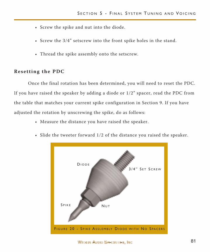
• Screw the spike and nut into the diode.
• Screw the 3/4” setscrew into the front spike holes in the stand.
• Thread the spike assembly onto the setscrew.
Resett ing the PDC
Once the final rotation has been determined, you will need to reset the PDC.
If you have raised the speaker by adding a diode or 1/2” spacer, read the PDC from
the table that matches your current spike configuration in Section 9. If you have
adjusted the rotation by unscrewing the spike, do as follows:
• Measure the distance you have raised the speaker.
• Slide the tweeter forward 1/2 of the distance you raised the speaker.
S E C T I O N 5 - F I N A L S Y S T E M T U N I N G A N D V O I C I N G
D I O D E
S P I K E
3 / 4 ” S E T S C R E W
N U T
F I G U R E 2 0 - S P I K E A S S L E M B LY D I O D E W I T H N O S PA C E R S
82
Note: If you lowered the speaker, then the tweeter will slide back 1/2 of the
lowered distance.
Every system has a unique time and phase character, which can effect the
PDC accuracy. Because of this, you may find that sliding the tweeter forward or
backwards a few positions increases the clarity and correctness of your Center
channel. If you like, experiment with the tweeter position and lock it in position
when you find the location you feel to be most accurate.
Integrat ing the Surround Channels
• Follow the processor instructions on level adjustment. Adjust the level
on the Surround channels so they match in level with the front chan-
nels.
• Play a DVD that has a scene with something moving around the room.
Listen for the correct spacial imaging. A correctly adjusted Surround
channel will have good imaging characteristics, seamlessly blended,
and should be just as transparent as the front channels.
• Adjust the rotation of the Surround channel until you find the best
integration.
Note: The Surround channel rotates on the upper two spikes. Examine careful-
ly this rotation and the mounting bracket before trying to adjust the angle of
rotation. Be careful when rotating the speaker as it is very heavy and could fall
off of the mounting bracket.
WAT C H C E N T E R C H A N N E L O W N E R ’ S M A N U A L
83
Integrat ing the WATCH Dog
The WATCH Dog will perform well in almost any location in the room. In
general, the closer you place the WATCH Dog to a wall or corner, the greater the
augmentation of the bass. However, the increase in bass comes at a cost of per-
ceived speed, dynamics, and bass clarity. We recommend that you experiment with
the placement of the subwoofer to find a balance of the above mentioned items
with which you are satisfied. For complete information on integrating a Wilson
Audio WATCH Dog, please refer to your WATCH Dog owner’s manual.
S E C T I O N 5 - F I N A L S Y S T E M T U N I N G A N D V O I C I N G

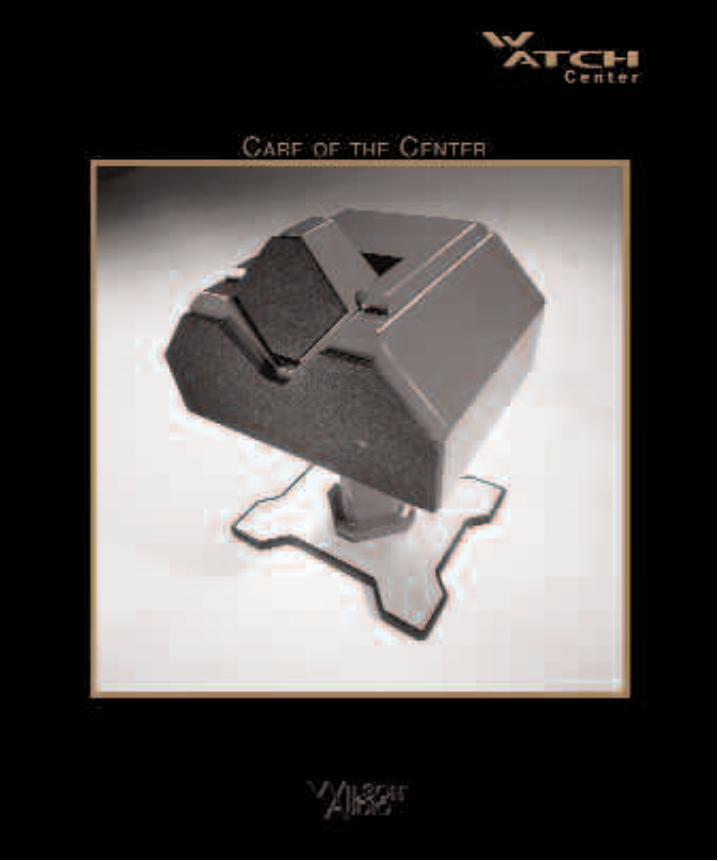
86
WAT C H C E N T E R C H A N N E L O W N E R ’ S M A N U A L
87
S e c t i o n 6 . 0 - C a r e o f t h e F i n i s h
The WATCH Center loudspeaker is hand painted with WilsonGloss™ paint
and hand polished to a high luster. While the finish seems quite dry to the touch,
final curing and complete hardening takes place over a period of several weeks.
Removing Protect ive Fi lm
To protect the finish of the WATCH Center during final manufacture, ship-
ment, and setup in the listening room, a removable layer of protective film has
been applied over the finish. It is recommended that this film be left in place until
the speakers are in their final location in the listening room. Once their final posi-
tion has been determined, remove the film by following this procedure:
1. Ensure the speaker surface is room temperature before removing the pro-
tective film. Removing the protective film when the speaker surface is
cold can damage the paint surface.
2. Slowly remove the film from the top down, large sections at a time, gently
pulling the film downward and outward. Tearing the film aggressivley can
damage the paint.
3. Take care in removing the protective film near edges and corners to pre-
vent paint damage in these areas.
4. The protective film should not be left on the painted surface for extended
periods of time nor exposed to heat sources and direct sunlight.
S E C T I O N 6 - C A R E O F T H E WAT C H C E N T E R C H A N N E L
88
Dusting the WATCH Center
It is important that the delicate paint finish of the WATCH Center be dust-
ed carefully with the dust cloth, which has been provided. We recommend that the
following procedure be observed when dusting the speakers:
• Blow off all loose dust.
• Using the special dust cloth as a brush, gently whisk off any remaining
loose dust.
• Shake out the dust cloth.
• Dust the finish, using linear motions in one direction parallel to the
floor. Avoid using circular or vertical motions.
Because the paint requires a period of several weeks to fully cure, we recom-
mend that no cleaning fluids, such as glass cleaners, be used during this initial
period of time. When the paint is fully cured, heavy fingerprints and other minor
smudges may be removed with a glass cleaner. Always use the dust cloth. Stronger
solvents are not recommended under any circumstances. Consult your dealer for
further information if required.
To maintain the high luster of the finish, periodic polishing may be
desired over the years. We recommend a nonabrasive carnauba-based wax and a
soft cloth.
WAT C H C E N T E R C H A N N E L O W N E R ’ S M A N U A L
89
S e c t i o n 6 . 1 - C a r e o f t h e G r i l l e s
Periodically, you will want to clean the Center’s grilles. This is best done by
using the round brush attachment on a vacuum cleaner hose. Gently vacuum the
front surface of the grille. Be careful not to apply too much pressure. Do not use a
hard plastic attachment against the grille. The grille cloth is stretched tightly over
the grille frame. Too much pressure or use of a hard plastic attachment could
cause the grille material to tear, especially in the corners.
Often Wilson speaker owners desire to change the look of their listening
room by changing the color of their speaker grilles. In addition to basic black,
Wilson Audio offers a variety of grille colors to match most WilsonGloss finishes.
Contact your local dealer for grille cloth samples or to order replacement grilles
for your Center.
S e c t i o n 6 . 2 - B r e a k - i n P e r i o d
All audio equipment will sound best after its components have been broken
in for some period of use. Wilson Audio breaks in all woofers and mid-range driv-
ers for a 12 hour period. All drivers are then tested, calibrated, and matched for
their acoustical properties. In your listening room, expect 25 to 50 percent of
break-in to be complete after two hours of playing music at normal listening levels.
Ninety percent of break-in is complete after 24 hours of playing. Playing a CD on
repeat overnight can accomplish this task quickly. Wilson Audio recommends
S E C T I O N 6 - C A R E O F T H E WAT C H C E N T E R C H A N N E L
90
chamber music for this task.
S e c t i o n 6 . 3 - E n c l o s u r e T e c h n o l o g y
Wilson Audio has conducted many hours of research on the impact of mate-
rials on speaker enclosure performance. Through this effort, Wilson pioneered the
use of non-resonant materials, first with the use of mineral filled acrylic in the
WATT, and continuing with the further development of proprietary materials for
X-1 Grand SLAMM and MAXX. Even the best materials are not suited to all
aspects of enclosure construction. Therefore, like all Wilson loudspeakers, the
WATCH Center is constructed of several exotic materials chosen for their specific
performance attributes relevant to different portions of the enclosure.
The Center is constructed using non-resonant, high-density, composites
which are then highly-cross braced to further reduce cabinet resonance. Each of
these composites meets and exceeds the highest of ANSI test standards for its use,
while offering very tight tolerances, high hardness, uniform density, and dimen-
sional stability. In the most critical areas of the enclosure, the WATCH Center
uses our proprietary “X” material, a very dense, strong composite developed for the
X-1 Grand SLAMM. The high hardness of these composites offers excellent
acoustical properties.
Adhesive
Wilson Audio has conducted exhaustive research into the best adhesives to
WAT C H C E N T E R C H A N N E L O W N E R ’ S M A N U A L
91
permanently bond our speaker enclosures. This is often an overlooked element
crucial to the proper performance of a loudspeaker. Correct modulus of elasticity,
coefficient of thermal expansion, and natural frequency response are just a few of
the important elements of adhesives.
A highly cross-linked, thermo-set adhesive is used for the construction of
the enclosure. It was also chosen for its excellent bond strength, solvent resist-
ance, hardness, and optimum vibrational characteristics.
Depth of Design
The Center’s compellingly authentic performance and lasting value are
achieved through careful implementation of cutting edge design and engineering
and then executed using the highest performance materials. Wilson Audio’s use of
proprietary enclosure materials and adhesives are employed to achieve truly excep-
tional speaker cabinet performance. The use of these materials in the WATCH
Center result in an enclosure that is inherently inert and non-resonant. All of these
structural aspects are combined, allowing Wilson Audio to deliver a product that
maintains the strictest structural tolerances, durability, and reliability. This also
means that the Center will have consistent, repeatable performance, unaffected by
the climatic conditions, anywhere in the world. Finally, like all Wilson products,
the WATCH Center is hand-crafted with meticulous attention to detail, with an
unwavering commitment to excellence. Thus, the WATCH Center will impart to
her owner beauty and pleasure for many years to come.
S E C T I O N 6 - C A R E O F T H E WAT C H C E N T E R C H A N N E L

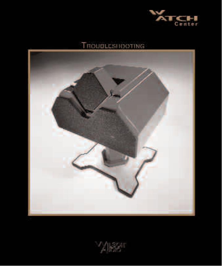

94
WAT C H C E N T E R C H A N N E L O W N E R ’ S M A N U A L
95
S e c t i o n 7 - T r o u b l e s h o o t i n g
One channel is not operating...
Imaging is off-center...
A chronic lack of bass energy...
S E C T I O N 7 - T R O U B L E S H O O T I N G
Check the interconnects from source.
Check the connections on the speaker
cables, both at the amplifier and speaker
ends. Watch especially for connectors
touching each other.
Check your connections. When a tweeter
or mid-range driver is not working, or is
out of phase, the imaging will be off.
Double check your connections for red-
to-red and black-to-black.
Play music at a low level and listen to
each driver in each channel. There may
be a driver that is not operating correct-
ly. If there is a driver that is silent,
please go to the “Driver Out” section of
this troubleshooting guide.
Check the input cable connections on the
enclosure. If one channel is out of phase
(connections reversed), bass will be can-
celled. Note: Turn off your amplifier,
and unplug it from the wall.
96
WAT C H C E N T E R C H A N N E L O W N E R ’ S M A N U A L
Driver out or not playing after connec-
tions have been verified:
Amplifier shuts off as soon as it isturned on:
If the problem is solved:
If the problem persists:
If the problem is solved:
If there is a driver with no output, poten-
tially the resistor is damaged and needs
replacing. Contact a local Wilson dealer
for replacement parts and service.
Check to see if the speaker cables are
properly secured. Look for frayed ends,
loose connections, or a conductor con-
tacting the amplifier chassis.
Turn the amplifier off and disconnect it
from the AC wall outlet. Disconnect the
preamplifier leads to the amplifier. Now
turn on the amplifier.
There is likely something wrong with
your preamplifier or interconnect.
Contact your dealer.
Leave the preamp leads disconnected and
continue to the next step.
Turn the amplifier off and disconnect it
from the AC wall outlet. Disconnect the
speaker leads at the main input to the
speaker. Now turn on the amplifier.
Call your Wilson Audio dealer. There
may be a problem with the crossover or
97
If the problem persists:
If the problem is solved:
If the problem persists:
the speaker’s internal wiring.
Continue to the next step.
Turn the amplifier off and disconnect it
from the AC wall outlet. Disconnect the
speaker cable leads to the amplifier and
turn the amplifier on again.
There is a short in the speaker cables.
Check for frayed ends, holes (from spike
feet), or make sure that the spade lug is
not touching the chassis while it is con-
nected to the binding post.
Call the dealer where the amplifier was
purchased. There appears to be a prob-
lem with this component.
S E C T I O N 7 - T R O U B L E S H O O T I N G


100
WAT C H C E N T E R C H A N N E L O W N E R ’ S M A N U A L
101
S e c t i o n 8 - C e n t e r C h a n n e l S p e c i f i c a t i o n s
Specif icat ions
Woofers: 2 - 6.5 inch {16.51 cm}
Tweeter: 1 - 1 inch {2.54 cm} inverted titanium dome
Sensitivity: 94 dB (2.00 V measured at 1 meter)
Nominal Impedance: 4 ohms
Minimum Amplifier Power: 7 WATTS per channel
Frequency Response (with port contribution): 45 Hz - 22.5 kHz (+ 0, -3 dB)
Dimensions
Height: 12.5 inches {31.75 cm}
Width: 20 inches {50.8 cm}
Depth: 16 inches {40.64 cm}
Uncrated Weight: 70 lbs {31.82 kgs}
System Shipping Weight (approx.): 95 lbs. {43.18 kgs}
S E C T I O N 8 - WAT C H C E N T E R C H A N N E L S P E C I F I C AT I O N S
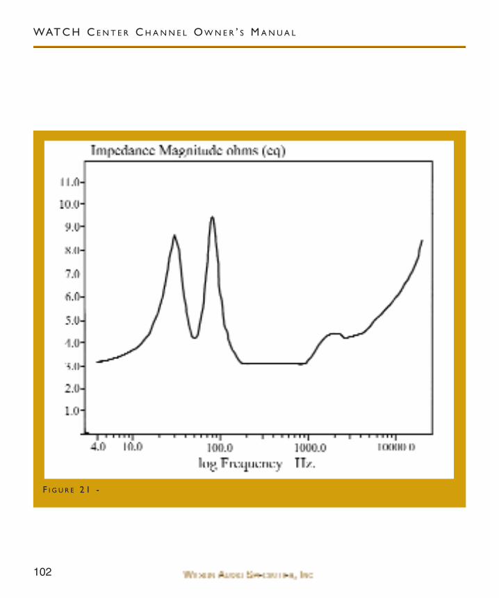
102
WAT C H C E N T E R C H A N N E L O W N E R ’ S M A N U A L
F I G U R E 2 1 -

103
S E C T I O N 8 - WAT C H C E N T E R C H A N N E L S P E C I F I C AT I O N S


106
WAT C H C E N T E R C H A N N E L O W N E R ’ S M A N U A L
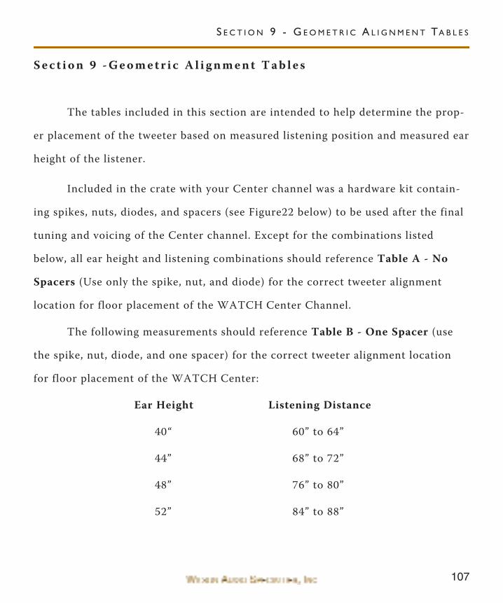
107
S e c t i o n 9 - G e o m e t r i c A l i g n m e n t T a b l e s
The tables included in this section are intended to help determine the prop-
er placement of the tweeter based on measured listening position and measured ear
height of the listener.
Included in the crate with your Center channel was a hardware kit contain-
ing spikes, nuts, diodes, and spacers (see Figure22 below) to be used after the final
tuning and voicing of the Center channel. Except for the combinations listed
below, all ear height and listening combinations should reference Table A - No
Spacers (Use only the spike, nut, and diode) for the correct tweeter alignment
location for floor placement of the WATCH Center Channel.
The following measurements should reference Table B - One Spacer (use
the spike, nut, diode, and one spacer) for the correct tweeter alignment location
for floor placement of the WATCH Center:
Ear Height Listening Distance
40“ 60” to 64”
44” 68” to 72”
48” 76” to 80”
52” 84” to 88”
S E C T I O N 9 - G E O M E T R I C A L I G N M E N T TA B L E S
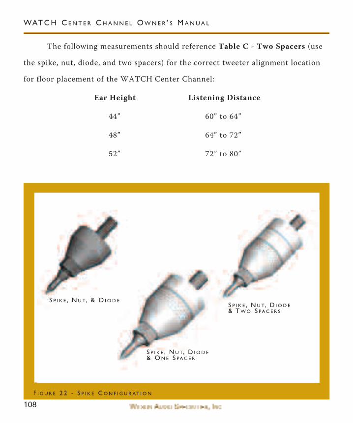
108
WAT C H C E N T E R C H A N N E L O W N E R ’ S M A N U A L
The following measurements should reference Table C - Two Spacers (use
the spike, nut, diode, and two spacers) for the correct tweeter alignment location
for floor placement of the WATCH Center Channel:
Ear Height Listening Distance
44” 60” to 64”
48” 64” to 72”
52” 72” to 80”
S P I K E , N U T, & D I O D E
S P I K E , N U T, D I O D E& O N E S PA C E R
S P I K E , N U T, D I O D E& T W O S PA C E R S
F I G U R E 2 2 - S P I K E C O N F I G U R AT I O N
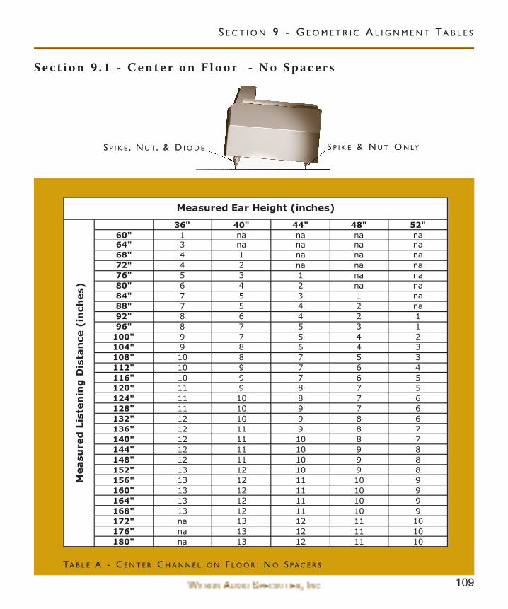
109
S e c t i o n 9 . 1 - C e n t e r o n F l o o r - N o S p a c e r s
36" 40" 44" 48" 52"60" 1 na na na na64" 3 na na na na68" 4 1 na na na72" 4 2 na na na76" 5 3 1 na na80" 6 4 2 na na84" 7 5 3 1 na88" 7 5 4 2 na92" 8 6 4 2 196" 8 7 5 3 1
100" 9 7 5 4 2104" 9 8 6 4 3108" 10 8 7 5 3112" 10 9 7 6 4116" 10 9 7 6 5120" 11 9 8 7 5124" 11 10 8 7 6128" 11 10 9 7 6132" 12 10 9 8 6136" 12 11 9 8 7140" 12 11 10 8 7144" 12 11 10 9 8148" 12 11 10 9 8152" 13 12 10 9 8156" 13 12 11 10 9160" 13 12 11 10 9164" 13 12 11 10 9168" 13 12 11 10 9172" na 13 12 11 10176" na 13 12 11 10180" na 13 12 11 10
Measu
red
Lis
ten
ing
Dis
tan
ce(i
nch
es)
Measured Ear Height (inches)
TA B L E A - C E N T E R C H A N N E L O N F L O O R : N O S PA C E R S
S E C T I O N 9 - G E O M E T R I C A L I G N M E N T TA B L E S
S P I K E , N U T, & D I O D E S P I K E & N U T O N LY
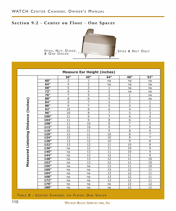
110
S e c t i o n 9 . 2 - C e n t e r o n F l o o r - O n e S p a c e r
WAT C H C E N T E R C H A N N E L O W N E R ’ S M A N U A L
36" 40" 44" 48" 52"60" 3 1 na na na64" 4 2 na na na68" 5 3 1 na na72" 6 4 2 na na76" 7 5 3 1 na80" 8 6 4 2 na84" 9 7 5 3 188" 9 7 5 3 292" 10 8 6 4 296" 10 8 7 5 3100" 11 9 7 6 4104" 11 9 8 6 5108" 11 10 8 7 5112" 12 10 9 7 6116" 12 11 9 8 6120" 13 11 10 8 7124" 13 11 10 9 7128" 13 12 10 9 8132" 13 12 11 10 8136" na 12 11 10 9140" na 13 11 10 9144" na 13 12 11 9148" na 13 12 11 10152" na 13 12 11 10156" na na 13 11 10160" na na 13 12 11164" na na 13 12 11168" na na 13 12 11172" na na 13 12 11176" na na na 13 12180" na na na 13 12
Measure Ear Height (inches)
Measu
red
Lis
ten
ing
Dis
tan
ce(i
nch
es)
TA B L E B - C E N T E R C H A N N E L O N F L O O R : O N E S PA C E R
S P I K E , N U T, D I O D E ,& O N E S PA C E R
S P I K E & N U T O N LY
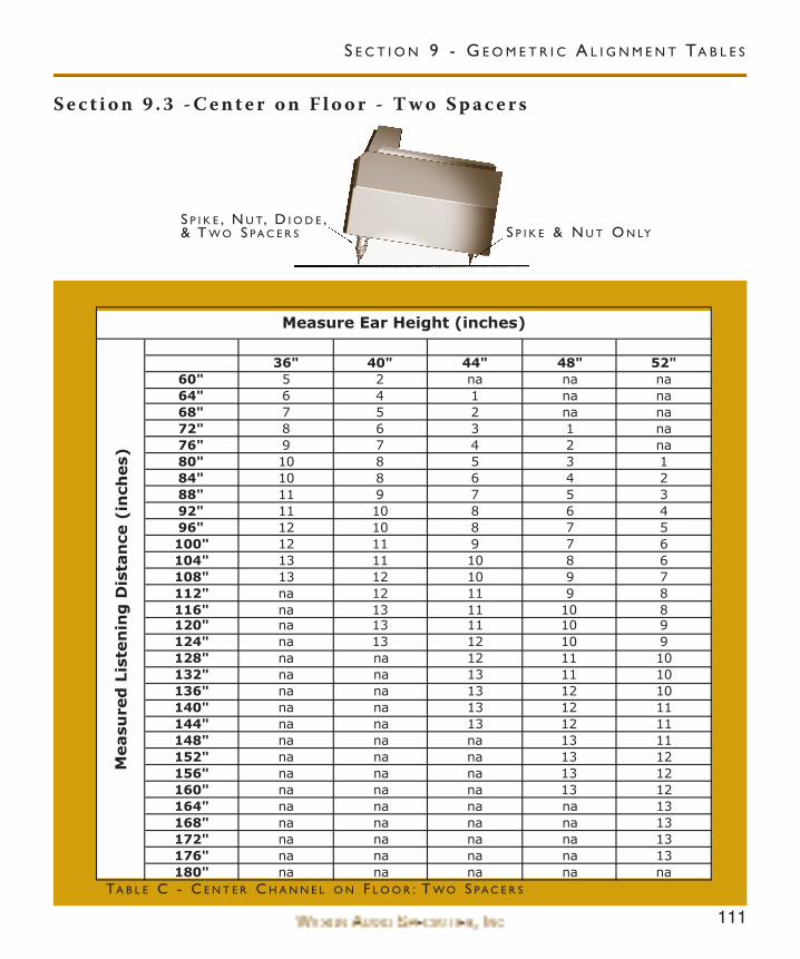
111
S e c t i o n 9 . 3 - C e n t e r o n F l o o r - T w o S p a c e r s
36" 40" 44" 48" 52"60" 5 2 na na na64" 6 4 1 na na68" 7 5 2 na na72" 8 6 3 1 na76" 9 7 4 2 na80" 10 8 5 3 184" 10 8 6 4 288" 11 9 7 5 392" 11 10 8 6 496" 12 10 8 7 5100" 12 11 9 7 6104" 13 11 10 8 6108" 13 12 10 9 7112" na 12 11 9 8116" na 13 11 10 8120" na 13 11 10 9124" na 13 12 10 9128" na na 12 11 10132" na na 13 11 10136" na na 13 12 10140" na na 13 12 11144" na na 13 12 11148" na na na 13 11152" na na na 13 12156" na na na 13 12160" na na na 13 12164" na na na na 13168" na na na na 13172" na na na na 13176" na na na na 13180" na na na na na
Measu
red
Lis
ten
ing
Dis
tan
ce(i
nch
es)
Measure Ear Height (inches)
TA B L E C - C E N T E R C H A N N E L O N F L O O R : T W O S PA C E R S
S E C T I O N 9 - G E O M E T R I C A L I G N M E N T TA B L E S
S P I K E & N U T O N LYS P I K E , N U T, D I O D E ,& T W O S PA C E R S
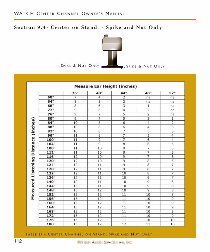
112
S e c t i o n 9 . 4 - C e n t e r o n S t a n d - S p i k e a n d N u t O n l y
WAT C H C E N T E R C H A N N E L O W N E R ’ S M A N U A L
36" 40" 44" 48" 52"60" 7 4 2 na na64" 8 5 2 na na68" 8 6 3 1 na72" 9 6 4 2 na76" 9 7 5 2 na80" 9 7 5 3 184" 10 8 6 4 288" 10 8 6 4 392" 10 8 7 5 396" 11 9 7 5 4100" 11 9 7 6 4104" 11 9 8 6 5108" 11 10 8 7 5112" 11 10 8 7 5116" 12 10 9 7 6120" 12 10 9 8 6124" 12 11 9 8 7128" 12 11 9 8 7132" 12 11 10 8 7136" 12 11 10 9 7140" 12 11 10 9 8144" 13 11 10 9 8148" 13 12 10 9 8152" 13 12 11 10 8156" 13 12 11 10 9160" 13 12 11 10 9164" 13 12 11 10 9168" 13 12 11 10 9172" 13 12 11 10 9176" 13 12 11 10 10180" 13 12 12 11 10
Measu
red
Lis
ten
ing
Dis
tan
ce(i
nch
es)
Measure Ear Height (inches)
TA B L E D - C E N T E R C H A N N E L O N S TA N D : S P I K E A N D N U T O N LY
S P I K E & N U T O N LYS P I K E & N U T O N LY
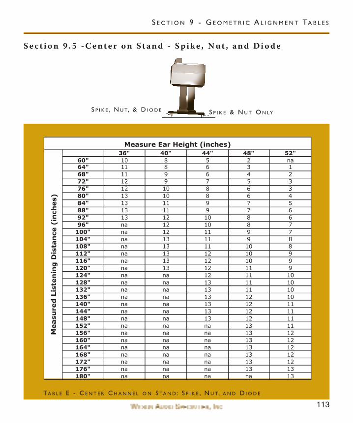
113
S e c t i o n 9 . 5 - C e n t e r o n S t a n d - S p i k e , N u t , a n d D i o d e
36" 40" 44" 48" 52"60" 10 8 5 2 na64" 11 8 6 3 168" 11 9 6 4 272" 12 9 7 5 376" 12 10 8 6 380" 13 10 8 6 484" 13 11 9 7 588" 13 11 9 7 692" 13 12 10 8 696" na 12 10 8 7
100" na 12 11 9 7104" na 13 11 9 8108" na 13 11 10 8112" na 13 12 10 9116" na 13 12 10 9120" na 13 12 11 9124" na na 12 11 10128" na na 13 11 10132" na na 13 11 10136" na na 13 12 10140" na na 13 12 11144" na na 13 12 11148" na na 13 12 11152" na na na 13 11156" na na na 13 12160" na na na 13 12164" na na na 13 12168" na na na 13 12172" na na na 13 12176" na na na 13 13180" na na na na 13
Measure Ear Height (inches)
Measu
red
Lis
ten
ing
Dis
tan
ce(i
nch
es)
TA B L E E - C E N T E R C H A N N E L O N S TA N D : S P I K E , N U T, A N D D I O D E
S E C T I O N 9 - G E O M E T R I C A L I G N M E N T TA B L E S
S P I K E & N U T O N LYS P I K E , N U T, & D I O D E

116
WAT C H C E N T E R C H A N N E L O W N E R ’ S M A N U A L
117
S e c t i o n 1 0 - W a r r a n t y I n f o r m a t i o n
Limited Warranty
Subject to the conditions set forth herein, Wilson Audio warrants its loud-
speakers to be free of manufacturing defects in material and workmanship for the
Warranty Period. The Warranty Period is a period of 90 days from the date of pur-
chase by the original purchaser, or if both of the following two requirements are
met, the Warranty Period is a period of five (5) years from the date of purchase by
the original purchaser:
Requirement No. 1. No later than 30 days after product delivery to
the customer. The customer must have returned the Warranty
Registration Form to Wilson Audio;
Requirement No. 2. The product must have been professionally
installed by the Wilson Audio dealer that sold the product to the cus-
tomer.
FAILURE TO COMPLY WITH EITHER REQUIREMENT NO. 1 OR
REQUIREMENT NO. 2 WILL RESULT IN THE WARRANTY PERIOD BEING
LIMITED TO A PERIOD OF 90 DAYS ONLY.
Conditions
This Limited Warranty is also subject to the following conditions and limita-
tions. The Limited Warranty is void and inapplicable if the product has been used
S E C T I O N 1 0 - WA R R A N T Y I N F O R M AT I O N
118
WAT C H C E N T E R C H A N N E L O W N E R ’ S M A N U A L
or handled other than in accordance with the instructions in the owner’s manual,
or has been abused or misused, damaged by accident or neglect or in being trans-
ported, or if the product has been tampered with or service or repair of the prod-
uct has been attempted or performed by anyone other than Wilson Audio, an
authorized Wilson Audio Dealer Technician or a service or repair center author-
ized by Wilson Audio to service or repair the product. Contact Wilson Audio at
(801) 377-2233 for information on location of Wilson Audio Dealers and author-
ized service and repair centers. Most repairs can be made in the field. In instances
where return to Wilson Audio’s factory is required, the dealer or customer must
first obtain a return authorization. Purchaser must pay for shipping to Wilson
Audio, and Wilson Audio will pay for shipping of its choice to return the product
to purchaser. A RETURNED PRODUCT MUST BE ACCOMPANIED BY A WRIT-
TEN DESCRIPTION OF THE DEFECT. Wilson Audio reserves the right to modify
the design of any product without obligation to purchasers of previously manufac-
tured products and to change the prices or specifications of any product without
notice or obligation to any person.
Remedy
In the event that the product fails to meet the above Limited Warranty and
the conditions set forth herein have been met, the purchaser’s sole remedy under
this Limited Warranty shall be to: (1) contact an authorized Wilson Audio Dealer
119
within the Warranty Period for service or repair of the product without charge for
parts or labor, which service or repair, at the Dealer’s option, shall take place
either at the location where the product is installed or at the Dealer’s place of busi-
ness; or (2) if purchaser has timely sought service or repair and the product cannot
be serviced or repaired by the Dealer, then purchaser may obtain a return authori-
zation from Wilson Audio and at purchaser’s expense return the product to Wilson
Audio where the defect will be rectified without charge for parts or labor.
Warranty Limited to Original Purchaser
This Limited Warranty is for the sole benefit of the original purchaser of the
covered product and shall not be transferred to a subsequent purchaser of the
product, unless the product is purchased by the subsequent purchaser from an
authorized Wilson Audio Dealer who has certified the product in accordance with
Wilson Audio standards and requirements and the certification has been accepted
by Wilson Audio, in which event the Limited Warranty for the product so pur-
chased and certified shall expire at the end of the original Warranty Period appli-
cable to the product.
Demonstrat ion Equipment
Equipment, while used by an authorized dealer for demonstration purposes,
is warranted to be free of manufacturing defects in materials and workmanship for
a period of five (5) years from the date of shipment to the dealer. Demo equipment
S E C T I O N 1 0 - WA R R A N T Y I N F O R M AT I O N
120
WAT C H C E N T E R C H A N N E L O W N E R ’ S M A N U A L
needing warranty service may be repaired on-site or, if necessary, correctly packed
and returned to Wilson Audio by the dealer at dealer’s sole expense. Wilson Audio
will pay return freight of its choice. A returned product must be accompanied by a
written description of the defect. Dealer owned demonstration equipment sold at
retail within two (2) years of date of shipment to the dealer is warranted to the
first retail customer to be free of manufacturing defects in materials and workman-
ship for the same time periods as if the product had originally been bought for
immediate resale to the retail customer. Wilson Audio products are warranted for
a period of 90 days, unless extended to 5 years, as provided above, by return and
filing of completed Warranty Registration at Wilson Audio within 30 days after
product delivery to customer and the product was professionally installed by the
Wilson Audio Dealer that sold the product to the customer.
Miscel laneous
ALL EXPRESS AND IMPLIED WARRANTIES NOT PROVIDED FOR HERE-
IN ARE HEREBY EXPRESSLY DISCLAIMED. ANY LEGALLY IMPOSED IMPLIED
WARRANTIES RELATING TO THE PORDUCT SHALL BE LIMITED TO THE
DURATION OF THIS LIMITED WARRANTY. THIS LIMITED WARRANTY DOES
NOT EXTEND TO ANY INCIDENTAL OR CONSEQUENTIAL COSTS OR DAM-
AGES TO THE PURCHASER. Some states do not allow limitations on how long an
implied warranty lasts or an exclusion or limitation of incidental or consequential

121
damages, so the above limitations or exclusions may not apply to you. This Limited
Warranty gives you specific legal rights, and you may also have other rights, which
vary from state to state.
S E C T I O N 1 0 - WA R R A N T Y I N F O R M AT I O N