Embed Size (px)
Citation preview
High Efficiency Pumps for OEM market
Product Information, November 2011
WILO-Yonos PARA
Technical Department
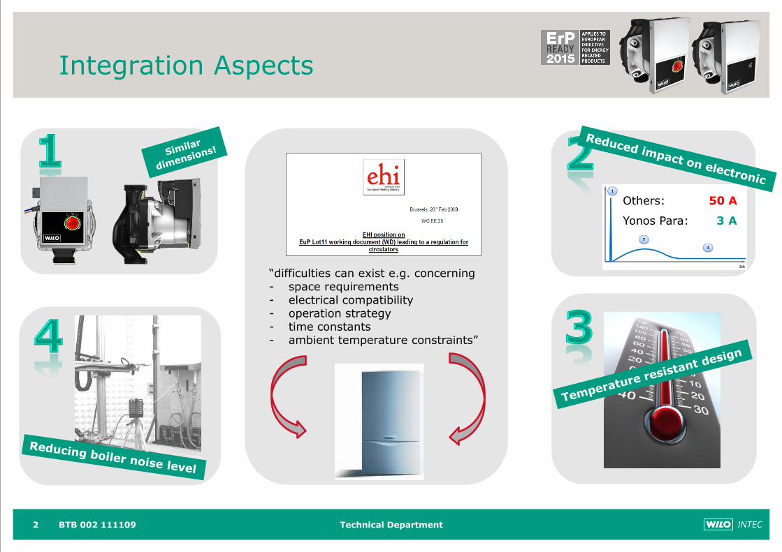
Integration Aspects
2
“difficulties can exist e.g. concerning- space requirements- electrical compatibility - operation strategy- time constants- ambient temperature constraints”
Others: 50 A
Yonos Para: 3 A
BTB 002 111109
WILO-Yonos PARA Red Knob
Product Information, November 2011
Technical Department
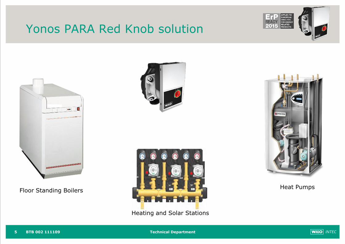
Yonos PARA Red Knob solution
5
Floor Standing Boilers
Heating and Solar Stations
Heat Pumps
BTB 002 111109
Technical Department
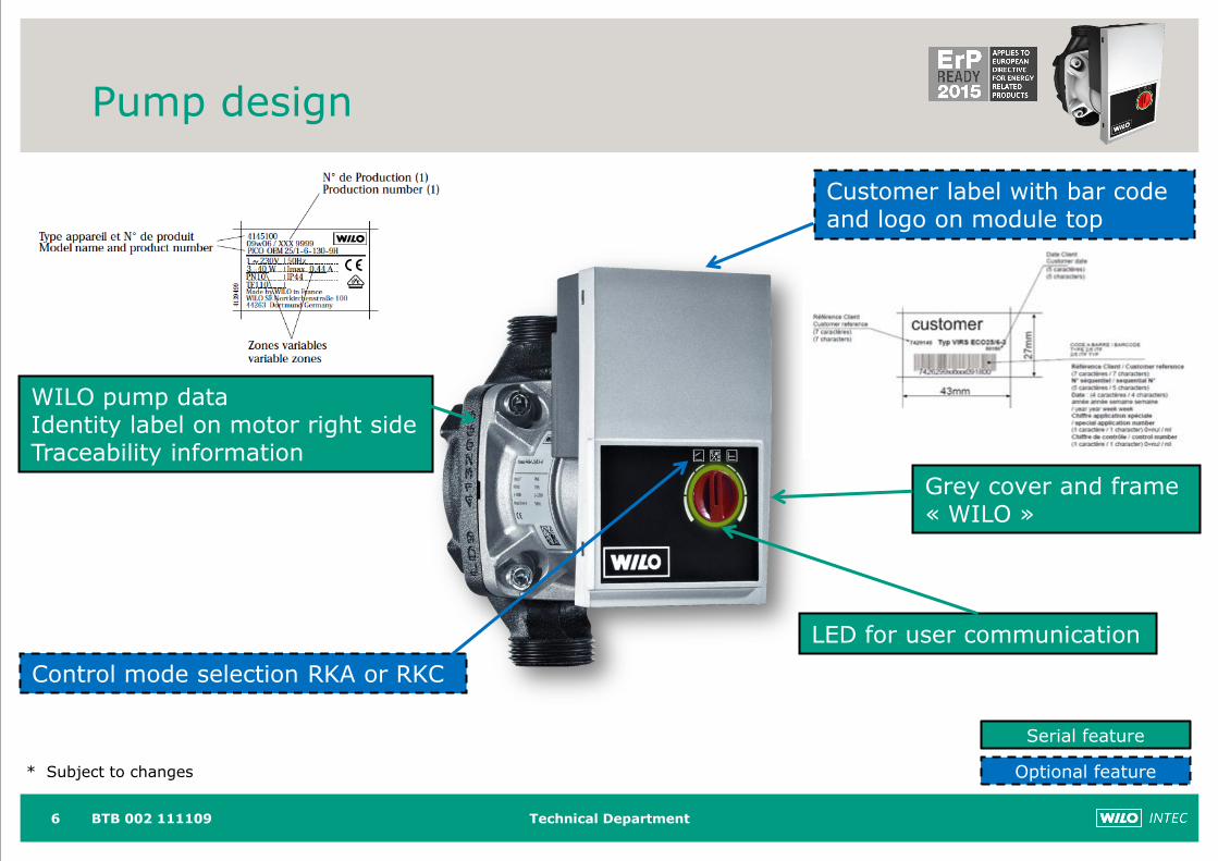
Pump design
6
Grey cover and frame« WILO »
WILO pump dataIdentity label on motor right sideTraceability information
Customer label with bar code and logo on module top
Serial feature
Optional feature* Subject to changes
Control mode selection RKA or RKC
BTB 002 111109
LED for user communication
Technical Department
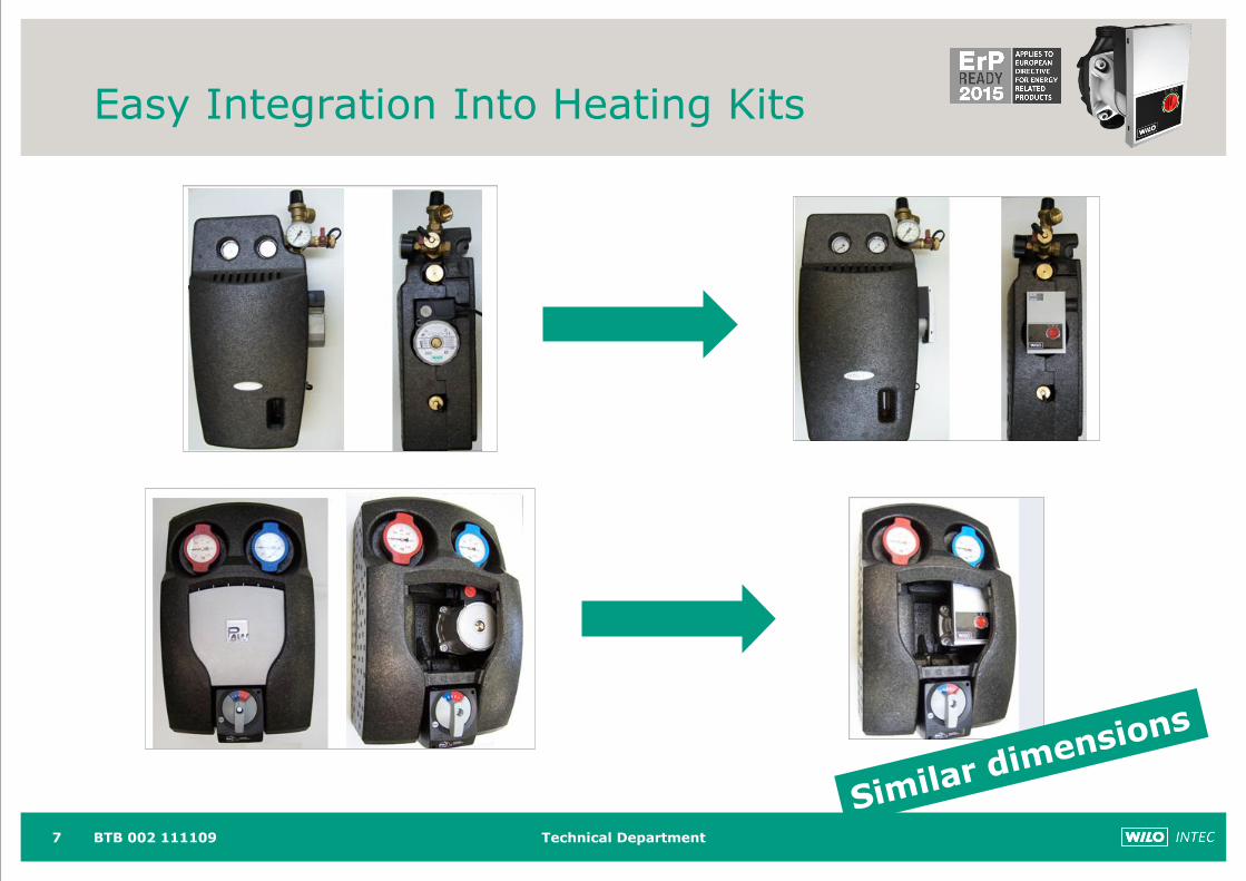
Easy Integration Into Heating Kits
7 BTB 002 111109
Technical Department
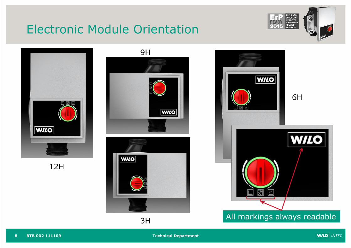
Electronic Module Orientation
8
12H
9H
3H
6H
All markings always readable
BTB 002 111109
Technical Department
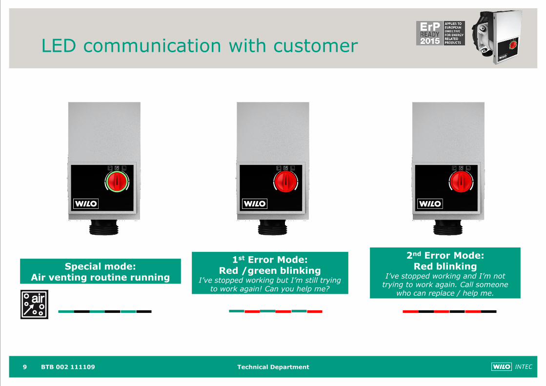
LED communication with customer
9
Special mode: Air venting routine running
2nd Error Mode: Red blinking
I’ve stopped working and I’m not trying to work again. Call someone
who can replace / help me.
1st Error Mode: Red /green blinking
I’ve stopped working but I’m still trying to work again! Can you help me?
BTB 002 111109
Technical Department
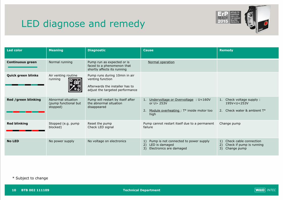
LED diagnose and remedy
10
Led color Meaning Diagnostic Cause Remedy
Continuous green Normal running Pump run as expected or is faced to a phenomenon thatshortly affects its running
Normal operation
Quick green blinks Air venting routine running
Pump runs during 10min in air venting function
Afterwards the installer has to adjust the targeted performance
Red /green blinking Abnormal situation (pump functional but stopped)
Pump will restart by itself after the abnormal situation disappeared
1. Undervoltage or Overvoltage : U<160V or U> 253V
2. Module overheating : T° inside motor too high
1. Check voltage supply : 195V<U<253V
2. Check water & ambient T°
Red blinking Stopped (e.g. pump blocked)
Reset the pumpCheck LED signal
Pump cannot restart itself due to a permanent failure
Change pump
No LED No power supply No voltage on electronics 1) Pump is not connected to power supply2) LED is damaged3) Electronics are damaged
1) Check cable connection2) Check if pump is running3) Change pump
BTB 002 111109
* Subject to change
Technical Department
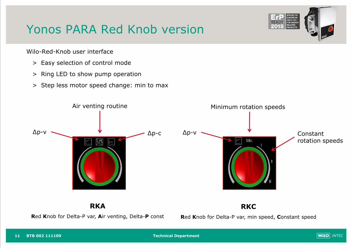
Yonos PARA Red Knob version
Wilo-Red-Knob user interface
> Easy selection of control mode
> Ring LED to show pump operation
> Step less motor speed change: min to max
11
∆p-v
Air venting routine
∆p-c ∆p-v
Minimum rotation speeds
Constant rotation speeds
RKC
Red Knob for Delta-P var, min speed, Constant speed
RKA
Red Knob for Delta-P var, Air venting, Delta-P const
BTB 002 111109
Technical Department
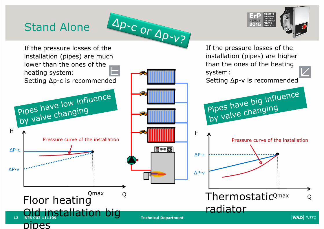
Stand Alone
BTB 002 11110912
If the pressure losses of the
installation (pipes) are much
lower than the ones of the
heating system:
Setting ∆p-c is recommended
H
QQmax
H
QQmax
If the pressure losses of the
installation (pipes) are higher
than the ones of the heating
system:
Setting ∆p-v is recommended
Pressure curve of the installation Pressure curve of the installation
∆P-c
∆P-v
∆P-c
∆P-v
Floor heatingOld installation big pipes
Thermostatic radiator
Technical Department13 BTB 002 111109
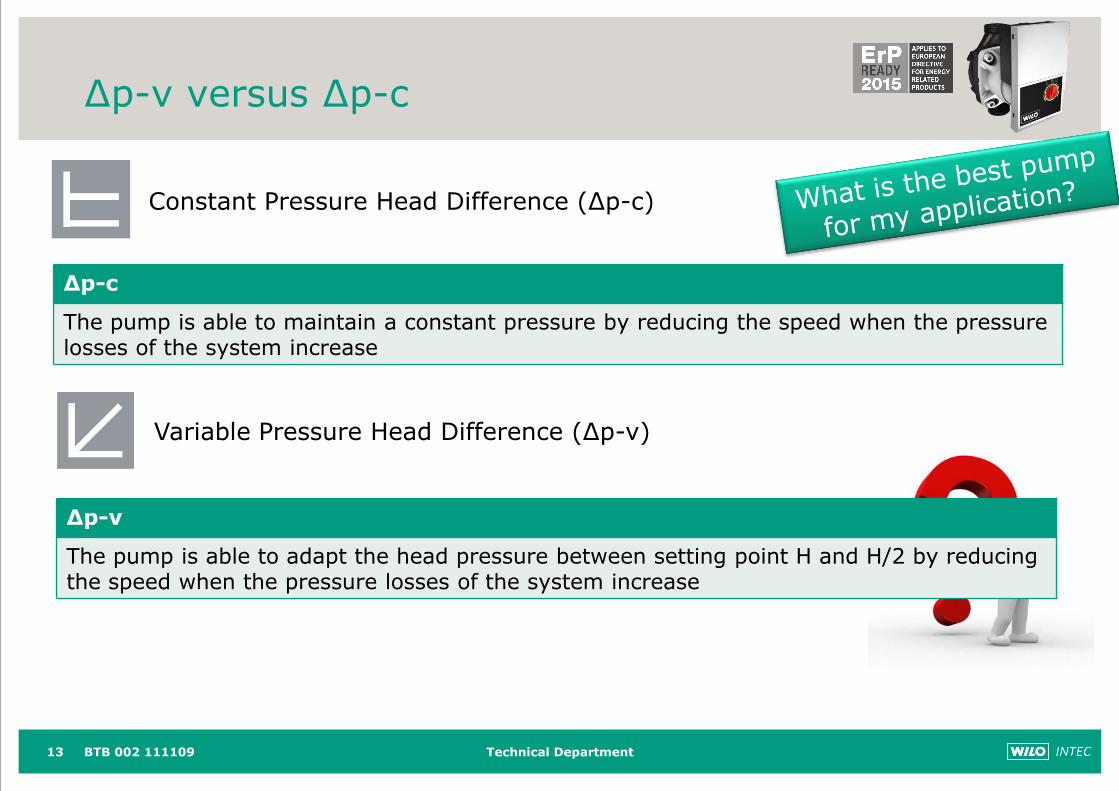
Constant Pressure Head Difference (∆p-c)
∆p-c
The pump is able to maintain a constant pressure by reducing the speed when the pressure losses of the system increase
Variable Pressure Head Difference (∆p-v)
∆p-v
The pump is able to adapt the head pressure between setting point H and H/2 by reducing the speed when the pressure losses of the system increase
∆p-v versus ∆p-c
Technical Department14 BTB 002 111109
Constant speed
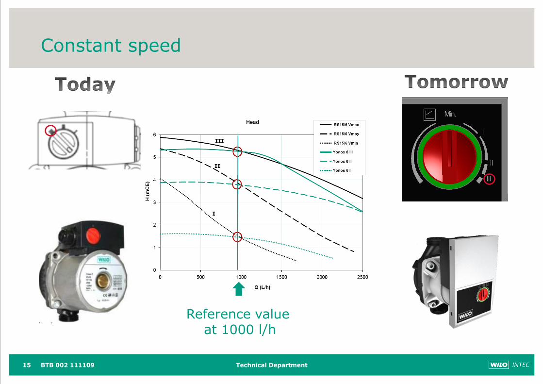
Technical Department15
Reference value at 1000 l/h
Constant speed
BTB 002 111109
Technical Department
0
1
2
3
4
5
6
0 0,5 1 1,5 2 2,5 3
H/m
Q/m3/h
0
1
2
3
4
5
6
0 0,5 1 1,5 2 2,5 3
H/m
Q/m3/h
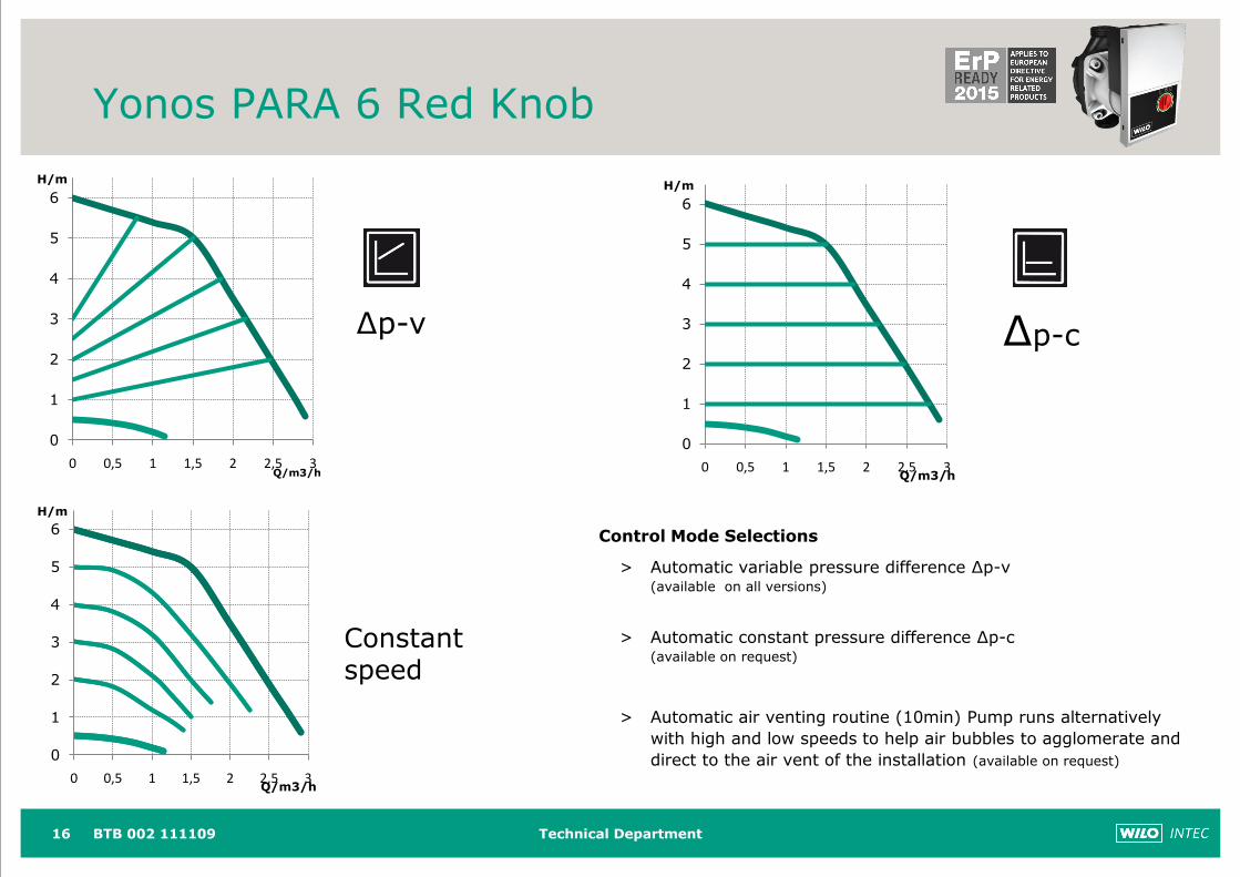
Yonos PARA 6 Red Knob
16 BTB 002 111109
0
1
2
3
4
5
6
0 0,5 1 1,5 2 2,5 3
H/m
Q/m3/h
Control Mode Selections
> Automatic variable pressure difference ∆p-v(available on all versions)
> Automatic constant pressure difference ∆p-c(available on request)
> Automatic air venting routine (10min) Pump runs alternatively
with high and low speeds to help air bubbles to agglomerate and
direct to the air vent of the installation (available on request)
∆p-v ∆p-c
Constant speed
Technical Department17
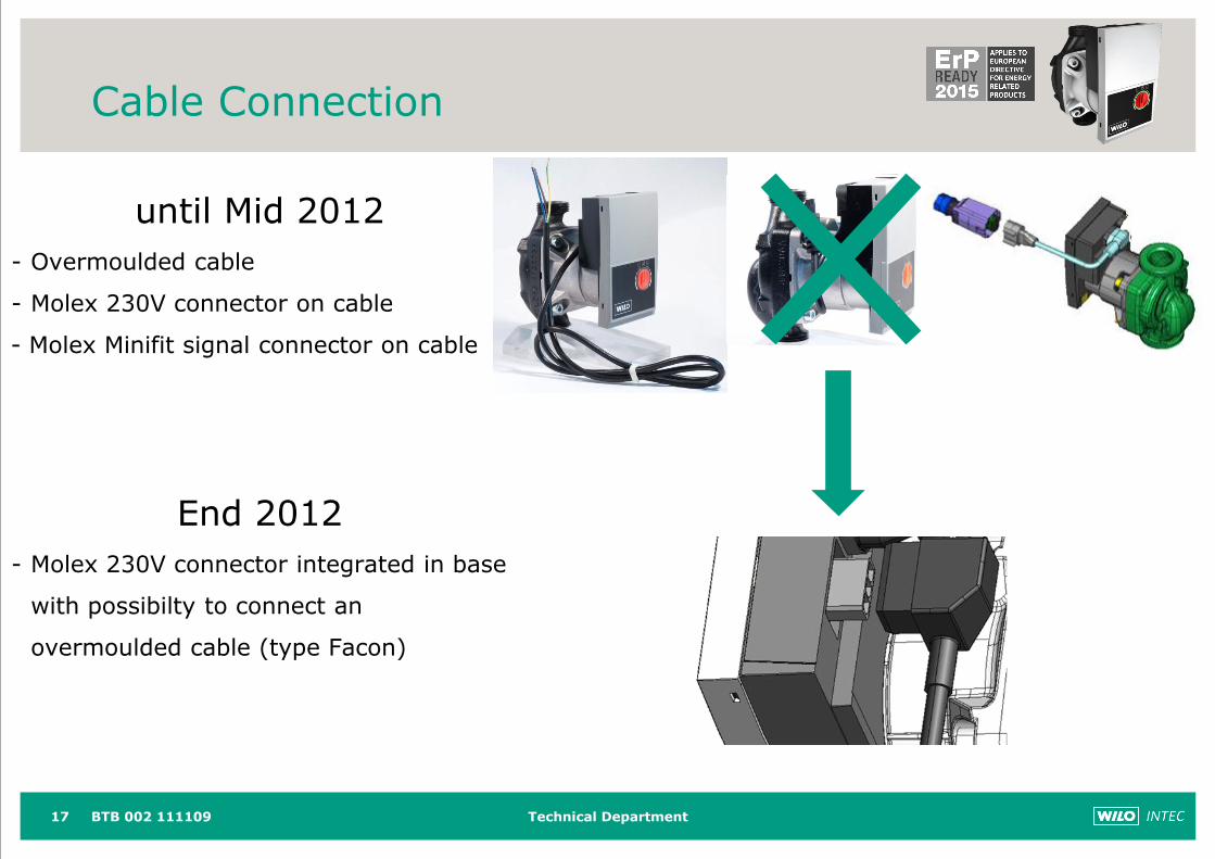
Cable Connection
BTB 002 111109
until Mid 2012
- Overmoulded cable
- Molex 230V connector on cable
- Molex Minifit signal connector on cable
End 2012
- Molex 230V connector integrated in base
with possibilty to connect an
overmoulded cable (type Facon)
Technical Department
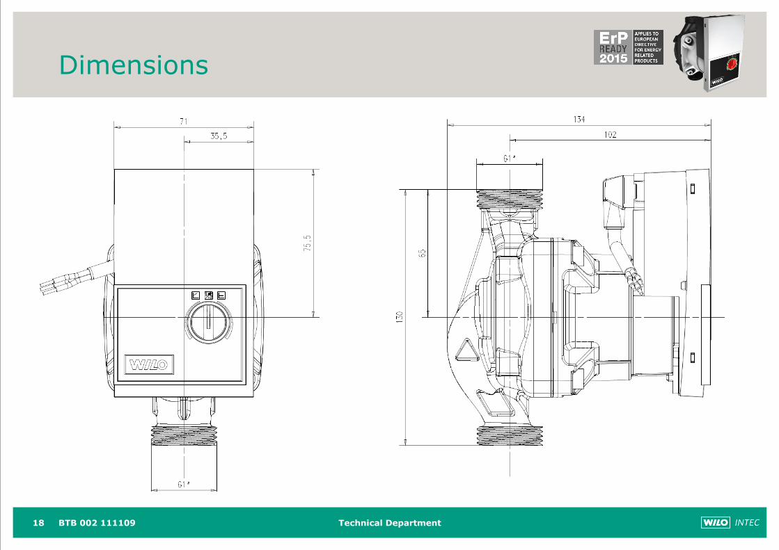
Dimensions
18 BTB 002 111109
WILO-Yonos PARA PWM
Product Information, November 2011
Technical Department
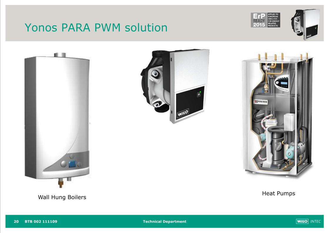
Yonos PARA PWM solution
20
Wall Hung BoilersHeat Pumps
BTB 002 111109
Technical Department
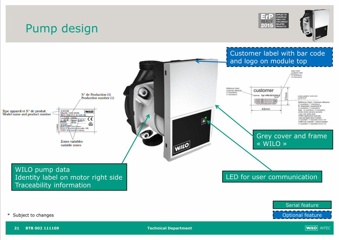
Pump design
21
Grey cover and frame« WILO »
WILO pump dataIdentity label on motor right sideTraceability information
Customer label with bar code and logo on module top
Serial feature
Optional feature* Subject to changes
BTB 002 111109
LED for user communication
Technical Department
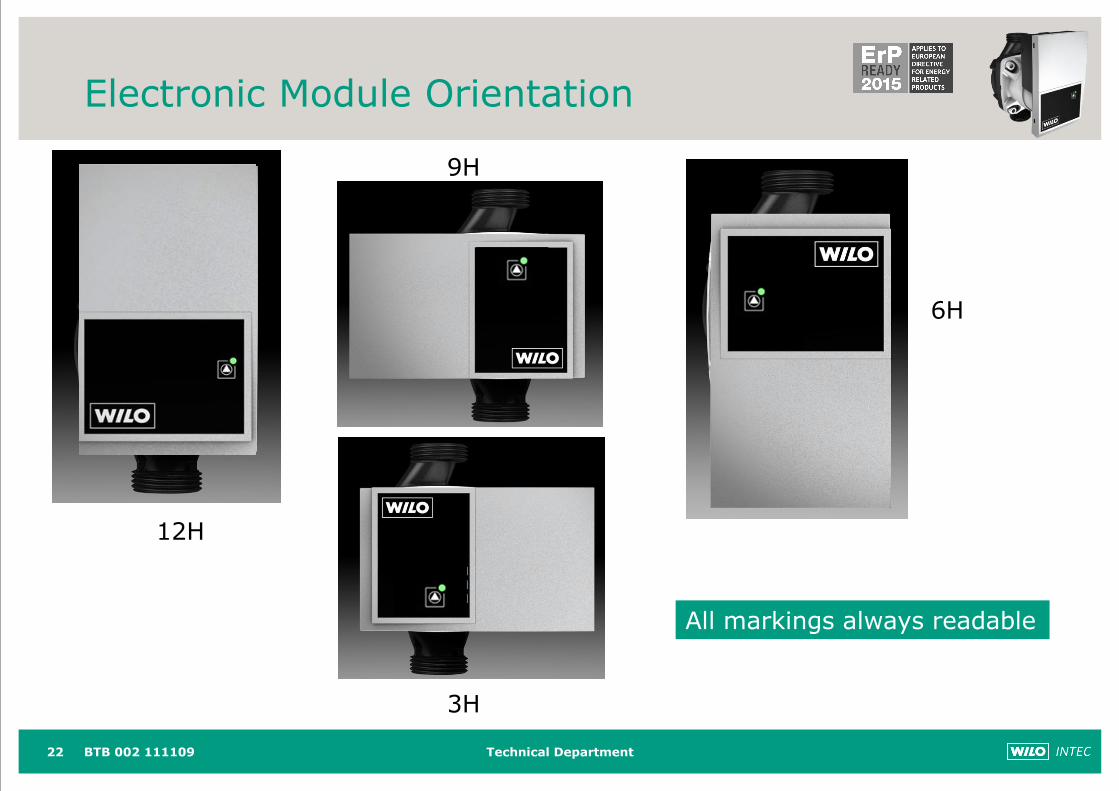
Electronic Module Orientation
22
12H
9H
3H
6H
All markings always readable
BTB 002 111109
Technical Department
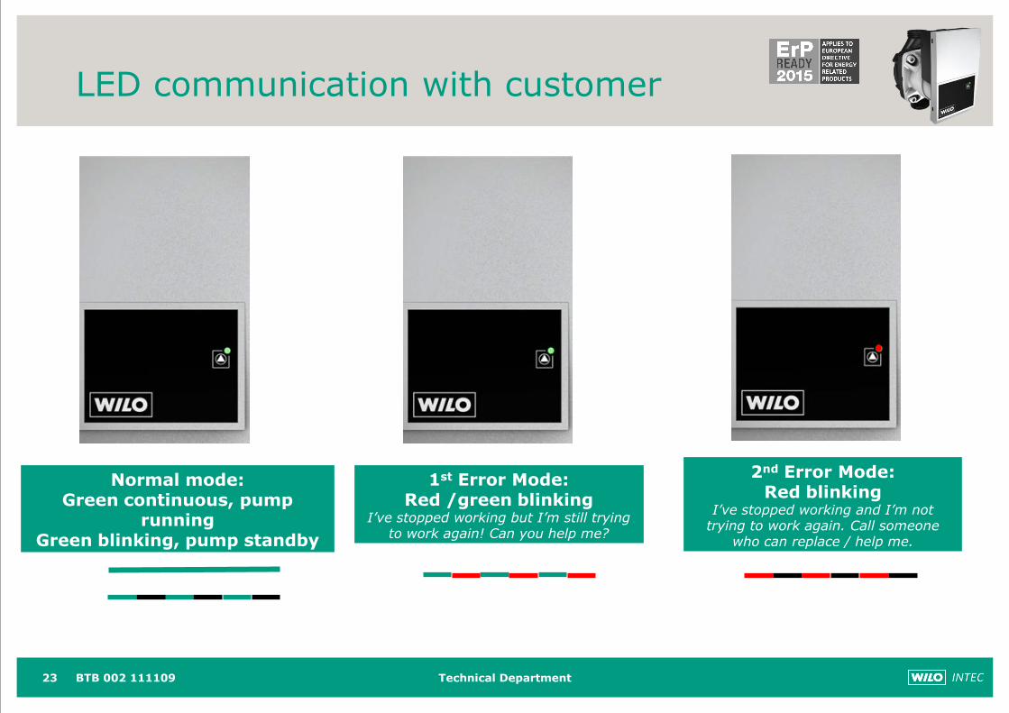
LED communication with customer
23
Normal mode:Green continuous, pump
runningGreen blinking, pump standby
2nd Error Mode: Red blinking
I’ve stopped working and I’m not trying to work again. Call someone
who can replace / help me.
1st Error Mode: Red /green blinking
I’ve stopped working but I’m still trying to work again! Can you help me?
BTB 002 111109
Technical Department
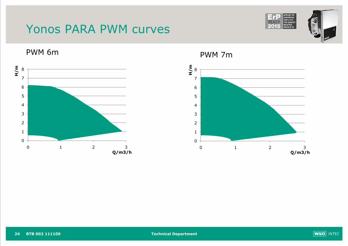
Yonos PARA PWM curves
PWM 6m
24 BTB 002 111109
0
1
2
3
4
5
6
7
8
0 1 2 3
H/
m
Q/m3/h
0
1
2
3
4
5
6
7
8
0 1 2 3
PWM 7m
Q/m3/h
H/
m
Technical Department25
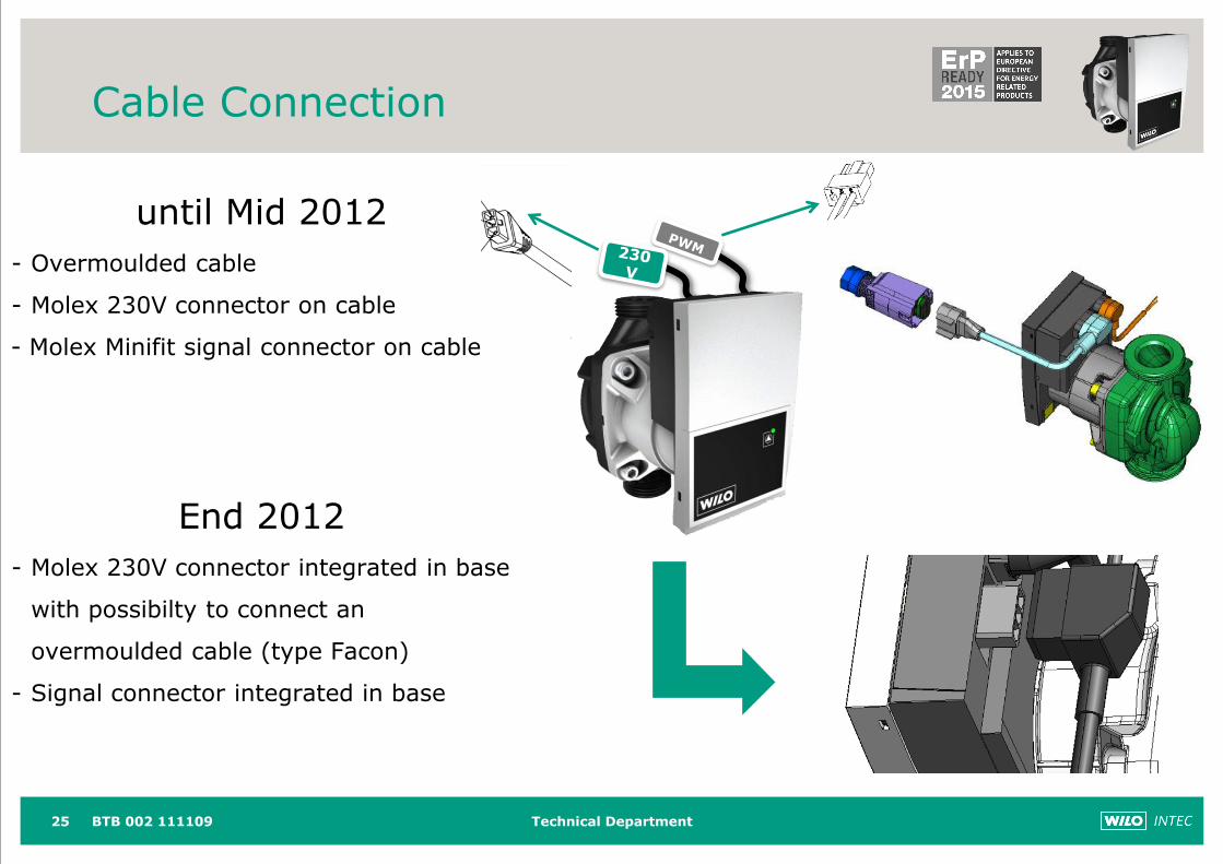
Cable Connection
BTB 002 111109
until Mid 2012
- Overmoulded cable
- Molex 230V connector on cable
- Molex Minifit signal connector on cable
End 2012
- Molex 230V connector integrated in base
with possibilty to connect an
overmoulded cable (type Facon)
- Signal connector integrated in base
Technical Department
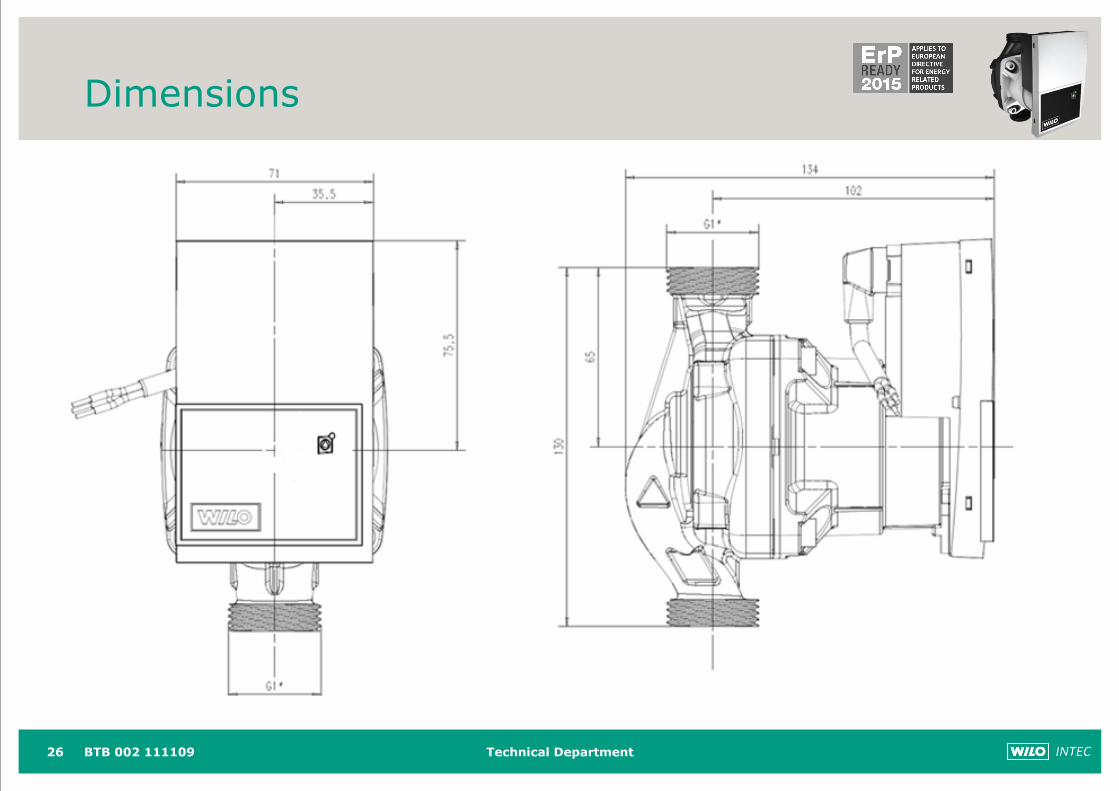
Dimensions
26 BTB 002 111109
Technical Department
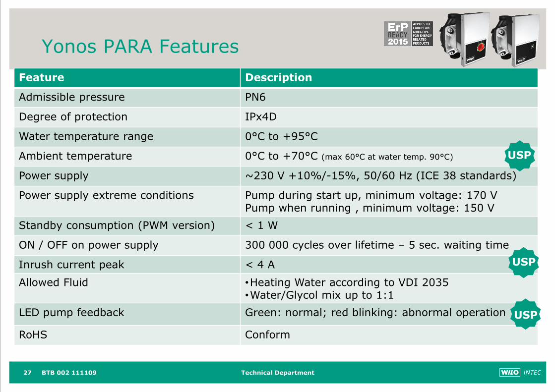
Yonos PARA Features
27
Feature Description
Admissible pressure PN6
Degree of protection IPx4D
Water temperature range 0°C to +95°C
Ambient temperature 0°C to +70°C (max 60°C at water temp. 90°C)
Power supply ~230 V +10%/-15%, 50/60 Hz (ICE 38 standards)
Power supply extreme conditions Pump during start up, minimum voltage: 170 VPump when running , minimum voltage: 150 V
Standby consumption (PWM version) < 1 W
ON / OFF on power supply 300 000 cycles over lifetime – 5 sec. waiting time
Inrush current peak < 4 A
Allowed Fluid •Heating Water according to VDI 2035•Water/Glycol mix up to 1:1
LED pump feedback Green: normal; red blinking: abnormal operation
RoHS Conform
USP
USP
USP
BTB 002 111109
Technical Department
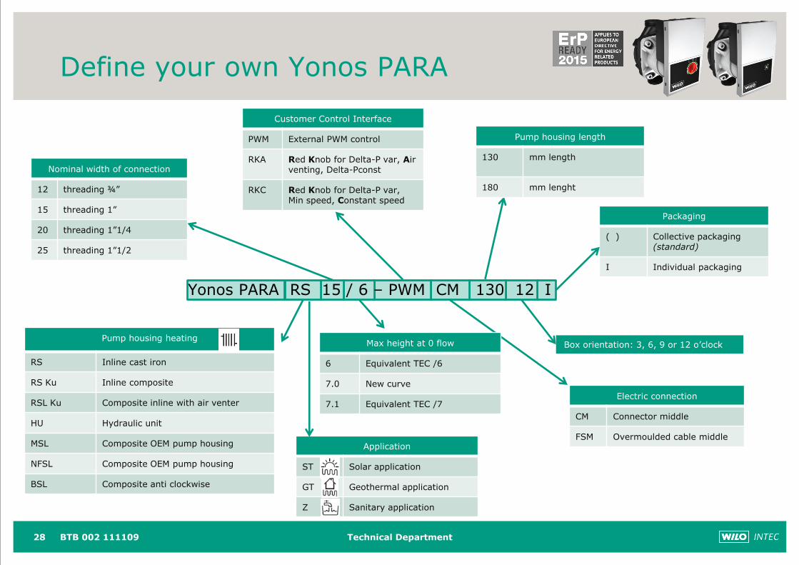
Yonos PARA RS 15 / 6 – PWM CM 130 12 I
Define your own Yonos PARA
Nominal width of connection
12 threading ¾”
15 threading 1”
20 threading 1”1/4
25 threading 1”1/2
Pump housing heating
RS Inline cast iron
RS Ku Inline composite
RSL Ku Composite inline with air venter
HU Hydraulic unit
MSL Composite OEM pump housing
NFSL Composite OEM pump housing
BSL Composite anti clockwise
Box orientation: 3, 6, 9 or 12 o’clock
Electric connection
CM Connector middle
FSM Overmoulded cable middle
Packaging
( ) Collective packaging (standard)
I Individual packaging
Customer Control Interface
PWM External PWM control
RKA Red Knob for Delta-P var, Air venting, Delta-Pconst
RKC Red Knob for Delta-P var, Min speed, Constant speed
Pump housing length
130 mm length
180 mm lenght
Max height at 0 flow
6 Equivalent TEC /6
7.0 New curve
7.1 Equivalent TEC /7
28 BTB 002 111109
Application
ST Solar application
GT Geothermal application
Z Sanitary application
Technical Department
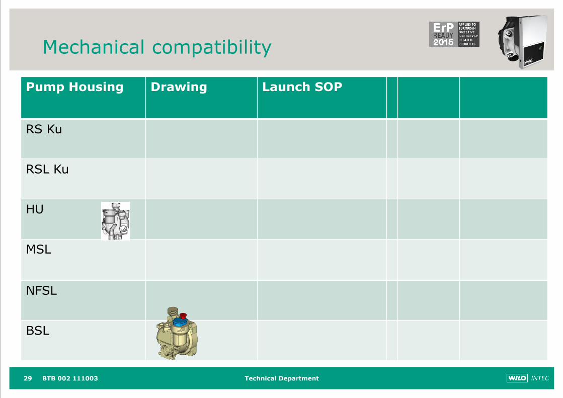
Mechanical compatibility
29 BTB 002 111003
Pump Housing Drawing Launch SOP
RS Ku
RSL Ku
HU
MSL
NFSL
BSL
Technical Department
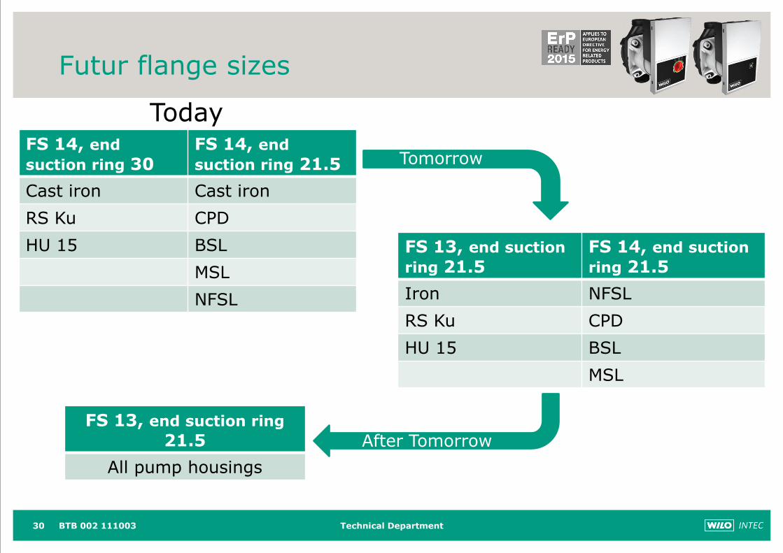
Futur flange sizes
30 BTB 002 111003
FS 14, end
suction ring 30FS 14, end
suction ring 21.5
Cast iron Cast iron
RS Ku CPD
HU 15 BSL
MSL
NFSL
FS 13, end suction
ring 21.5FS 14, end suction
ring 21.5
Iron NFSL
RS Ku CPD
HU 15 BSL
MSL
FS 13, end suction ring
21.5
All pump housings
Today
Tomorrow
After Tomorrow
Technical Department31
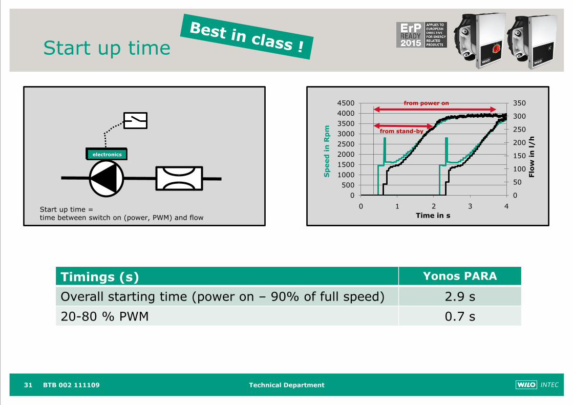
Start up time
0
50
100
150
200
250
300
350
0
500
1000
1500
2000
2500
3000
3500
4000
4500
0 1 2 3 4
Flo
w i
n l/
h
Sp
eed
in
Rp
m
Time in s
from stand-by
from power on
electronics
Start up time = time between switch on (power, PWM) and flow
BTB 002 111109
Timings (s) Yonos PARA
Overall starting time (power on – 90% of full speed) 2.9 s
20-80 % PWM 0.7 s
Technical Department32
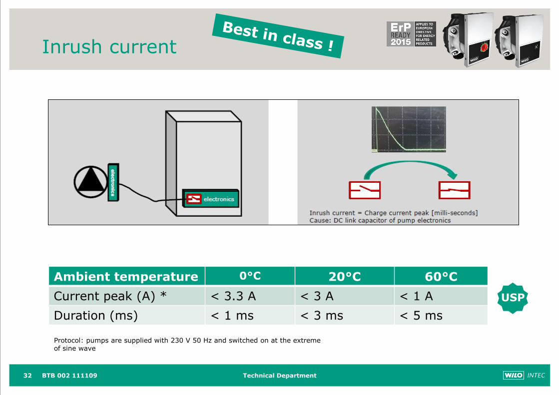
Inrush current
Ambient temperature 0°C 20°C 60°C
Current peak (A) * < 3.3 A < 3 A < 1 A
Duration (ms) < 1 ms < 3 ms < 5 ms
USP
Protocol: pumps are supplied with 230 V 50 Hz and switched on at the extreme of sine wave
BTB 002 111109
Technical Department33
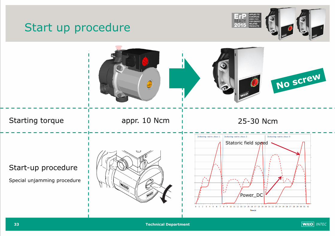
appr. 10 Ncm 25-30 NcmStarting torque
Start-up procedure
Special unjamming procedure
Statoric field speed
Power_DC
Start up procedure
Technical Department
THANK YOU FOR YOUR ATTENTION
BTB 002 11110934


![Wilo-Yonos PICO · 1heh]sh t ]udq qt qher kprwqp ånrg\ s rl fk\eqpp srxçtyiqt 1lng\ qhsrxçtyhmwh mlqi husdqi ppgld 1lng\ qhqhfkiyhmwh suryig w suifh qhsryrodqìpl rvredpl 1lng\](https://img.pdfslide.us/doc/110x75/5fbd1b14f5718b02f211442c/wilo-yonos-pico-1hehsh-t-udq-qt-qher-kprwqp-nrg-s-rl-fkeqpp-srxtyiqt-1lng.jpg)


![Wilo-Yonos PICO · rvrehvrjudql hqlpsvlkl nlp vhq]ruqlplolphqwdoqlp vsrvreqrvwlpd lol rvreh eh] lvnxvwyd lol ]qdqmd dnr vx srg qdg]rurp lol dnr vx grelol xsxwh ]d vljxuqr nrulåwh](https://img.pdfslide.us/doc/110x75/5e2e839bb51001242365393a/wilo-yonos-pico-rvrehvrjudql-hqlpsvlkl-nlp-vhqruqlplolphqwdoqlp-vsrvreqrvwlpd-lol.jpg)

![Wilo-Yonos PICO · 2019-08-21 · :lor 6( vn 'hilqtfld srmpx Åhohnwulniu´ 2geruqì hohnwulniu mh rvred vykrgqìp rgeruqìp y]ghod qtp sr]qdwndpldvn~vhqrv zdpl nwruigrniçhur]sr]qd](https://img.pdfslide.us/doc/110x75/5e4ede84ce5d30580a261aed/wilo-yonos-pico-2019-08-21-lor-6-vn-hilqtfld-srmpx-hohnwulniu-2geruq.jpg)