Embed Size (px)
Citation preview

de Einbau- und Betriebsanleitung
en Installation and operating instructions
fr Notice de montage et de mise en service
Wilo-Yonos PARA
4 52
3 67
6-Ed
.01
/ 201
2-05
-Wilo
APPLIES TOEUROPEANDIRECTIVEFOR ENERGYRELATEDPRODUCTS
Installation & Operating Instructions
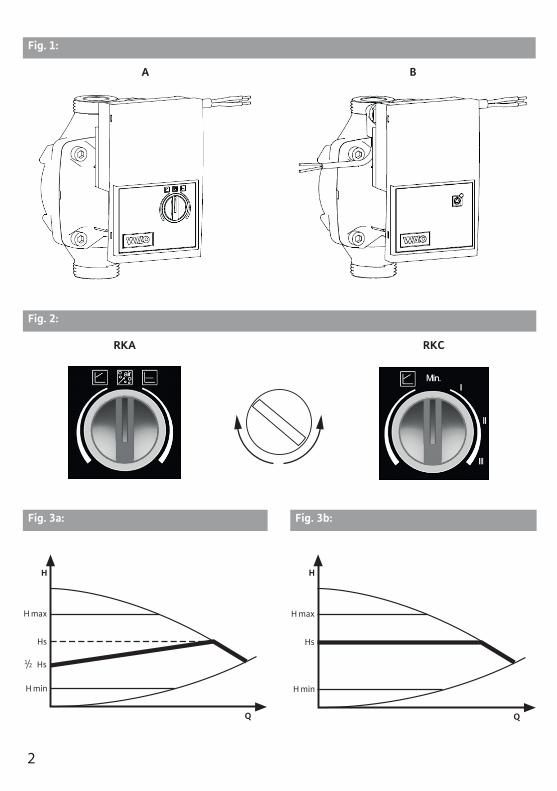
Fig. 1:
A B
Fig. 2:
RKA RKC
Fig. 3a: Fig. 3b:
H max
H
H min
Hs
Q
Hs1/2
H max
H
H min
Hs
Q
2

Fig. 3c: Fig. 3d:
Fig. 3e: Fig. 4:
Fig. 5:
a b
max
H
min
II
III
I
Q
max
n/¹/min
min
0 5 85 88 93 100 PWM %
max
min
0 7 12 15 95 100 PWM %
n/¹/min
PE N L
3
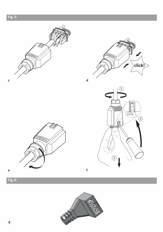
Fig. 5:
c d
e f
Fig. 6:
4
Installation and Operating Instructions Wilo-Yonos PARA 13
English
Installation and Operating Instructions1 GeneralAbout this documentThe language of the original operating instructions is English. All other languages of these instructions are translations of the original operating instructions.These installation and operating instructions are an integral part of the product. They must be kept readily available at the place where the product is installed. Strict adherence to these instructions is a precondition for the proper use and correct operation of the product.The installation and operating instructions correspond to the relevant version of the product and the underlying safety regulations and standards valid at the time of going to print.EC declaration of conformity:A copy of the EC declaration of conformity is a component of these operating instructions.If a technical modification is made on the designs named there without our agreement or the declarations made in the installation and operating instruc-tions on product/personnel safety are not observed, this declaration loses its validity.
2 SafetyThese operating instructions contain basic information which must be adhered to during installation, operation and maintenance. For this reason, these oper-ating instructions must, without fail, be read by the service technician and the responsible specialist/operator before installation and operation.It is not only the general safety instructions listed under the main point “safety” that must be adhered to but also the special safety instructions with danger symbols included under the following main points.
2.1 Indication of instructions in the operating manualSymbols:
General danger symbol
Danger due to electrical voltage
NOTE:
Signal words:
DANGER!Acutely dangerous situation.Non-observance results in death or the most serious of injuries.
WARNING!The user can suffer (serious) injuries. 'Warning' implies that (serious) injury to persons is probable if this information is disregarded.
CAUTION!There is a risk of damaging the product/unit. 'Caution' implies that damage to the product is possible if this information is disregarded.
5

English
14 WILO SE 05/2012
NOTE: Useful information on handling the product. It draws attention to possible pro-blems.
Information applied directly to the product, such as:• Direction of rotation arrow,• Identifiers for connections,• Name plate,• warning sticker,
must be strictly compliant with and kept in a fully legible condition.
2.2 Personnel qualificationsThe installation, operating and maintenance personnel must have the appropri-ate qualifications for this work. Area of responsibility, terms of reference and monitoring of the personnel have to be ensured by the operator. If the person-nel are not in possession of the necessary knowledge, they have to be trained and instructed. This can be accomplished if necessary by the manufacturer of the product at the request of the operator.
2.3 Danger in the event of non-observance of the safety instructionsNon-observance of the safety instructions can result in risk of injury to persons and damage to the environment and the product/unit. Non-observance of the safety instructions results in the loss of any claims to damages. In detail, non-observance can, for example, result in the following risks:
• Danger to persons from electrical, mechanical and bacteriological influences,• Damage to the environment due to leakage of hazardous materials,• Property damage,• Failure of important product/unit functions,• Failure of required maintenance and repair procedures.
2.4 Safety consciousness on the jobThe safety instructions included in this installation and operating instructions, the existing national regulations for accident prevention together with any internal working, operating and safety regulations of the operator are to be com-pliant with.
2.5 Safety instructions for the operatorThis appliance is not intended for use by persons (including children) with reduced physical, sensory or mental capabilities, or lack of experience and knowledge, unless they have been given supervision or instruction concerning use of the appliance by a person responsible for their safety. Children should be supervised to ensure that they do not play with the appli-ance.
• If hot or cold components on the product/the unit lead to hazards, local meas-ures must be taken to guard them against touching.
6
Installation and Operating Instructions Wilo-Yonos PARA 15
English
• Guards protecting against touching moving components (such as the coupling) must not be removed whilst the product is in operation.
• Leakages (e.g. from a shaft seal) of hazardous fluids (e.g. explosive, toxic or hot) must be led away so that no danger to persons or to the environment arises. National statutory provisions are to be complied with.
• Danger from electrical current must be eliminated. Local directives or general directives [e.g. IEC, VDE etc.] and local energy supply companies must be adhered to.
• Faults of electronic devices due to electromagnetic fields Electromagnetic fields are created during the operation of pumps with frequency converter. Interference of electronic devices may be the result. The result may be a device malfunction, which can result in damage to the health or even death, e.g. of per-sons carrying implanted active or passive medical devices.Therefore, during operation the presence of any persons e.g. with cardiac pace-makers in the vicinity of the unit/pump should be prohibited. With magnetic or electronic data media, the loss of data is possible.
WARNING! Danger due to strong magnetic field!Inside the machine there is always a strong magnetic field that can cause injury and damage to property in the event of incorrect dismantling.
• It is only permitted to have the rotor removed from the motor housing by qualified personnel!
• There is a crushing hazard! When pulling the rotor out of the motor, it may be suddenly pulled back into its initial position by the strong magnetic field.
• If the unit consisting of impeller, bearing shield and rotor is pulled out of the motor, persons with medical aids, such as cardiac pacemakers, insulin pumps, hearing aids, implants or similar are at risk. Death, severe injury and damage to property may be the result. For such persons, a professional medical assessment is always necessary.
• Electronic devices may be impaired functionally or damaged by the strong magnetic field of the rotor.
• If the rotor is outside the motor, magnetic objects may be attracted very suddenly. That can result in injury and damage to property.
In assembled condition, the rotor's magnetic field is guided in the motor's iron core. There is therefore no harmful magnetic field outside the machine.
2.6 Safety instructions for installation and maintenance workThe operator must ensure that all installation and maintenance work is carried out by authorized and qualified personnel, who are sufficiently informed from their own detailed study of the operating instructions.Work to the product/unit must only be carried out when at a standstill. It is man-datory that the procedure described in the installation and operating instruc-tions for shutting down the product/unit be complied with.Immediately on conclusion of the work, all safety and protective devices must be put back in position and/or re-commissioned.
7
English
16 WILO SE 05/2012
2.7 Unauthorised modification and manufacture of spare partsUnauthorised modification and manufacture of spare parts will impair the safety of the product/personnel and will make void the manufacturer's declarations regarding safety. Modifications to the product are only permissible after consultation with the manufacturer. Original spare parts and accessories authorised by the manufac-turer ensure safety. The use of other parts will absolve us of liability for conse-quential events.
2.8 Improper useThe operating safety of the supplied product is only guaranteed for conven-tional use in accordance with Section 4 of the operating instructions. The limit values must on no account fall under or exceed those specified in the catalogue/data sheet.
3 Transport and interim storageImmediately after receiving check the product for damage in transit.
CAUTION! Risk of damage to property!Incorrect transport and interim storage can cause damage to the product.The pump must be protected from moisture, frost and mechanical damage due to impact during transport and interim storage.
Transport conditionsThe device must not be exposed to temperatures outside the range of -40 °C up to +85 °C The transport conditions must be applied max. three months.
Storage conditionsThe device must not be exposed to temperatures outside the range 0 °C up to +40 °C. The storage time can be up to two years. The remaining water, in case of customer production tests, cannot lead to frost damages.
4 Intended useThe circulation pumps of the Wilo-Yonos PARA series are designed for hot-water heating systems and other similar systems with constantly changing vol-ume flows. Approved fluids are heating water in accordance with VDI 2035, water/glycol mixture at a mixing ratio of max. 1:1. If glycol is added, the delivery data of the pump must be corrected according to the higher viscosity, depend-ing on the mixing ratio percentage.Intended use also includes following these instructions.Any other use is regarded as incorrect use.
8

Installation and Operating Instructions Wilo-Yonos PARA 17
English
5 Product Information5.1 Type key
Example: Yonos PARA RS 15/6 RKA FS 130 12 I
Yonos PARA High Efficiency pumpRS Inline cast iron pump housing15 Threaded connection:
15 (Rp ½), 20 (Rp ¾), 25 (Rp 1), 30 (Rp 1¼)6 Maximum delivery head in [m] at Q = 0 m3/hRKA RKA = model with control knob for Δp-v, Δp-c
RKC = model with control knob for Δp-v, constant speed I,II,IIIPWM = external control via PWM signal
FS FS = overmoulded cable C = connector
130 Pump housing legth: 130 mm or 180 mm12 Control box orientation 12 o’clockI Individual packaging
5.2 Technical data
Approved fluids (other fluids on request)
Heating water (in accordance with VDI 2035)Water-glycol mixtures (max. 1:1; above 20% admix-ture, the pumping data must be checked)
PowerMax. delivery head (Hmax) 6,2 m (6 m model)
7,3 m (7 m model)Max. volume flow (Qmax) 3,3 m3/hPermitted field of applicationTemperature range for applications in heating and air-conditioning systems at max. ambient temperature. See nameplate for “TF” indication
Ambient 52 °C = TF 0 to 110 °Cof 57 °C = 0 to 95 °Cof 60 °C = 0 to 90 °Cof 67 °C = 0 to 70 °C
Max. operating pressure According information on the nameplateElectrical connectionMains connection 1~230 V +10%/-15%, 50/60 Hz (acc. IEC 60038)Motor/ElectronicsElectromagnetic compatibility EN 61800-3Emitted interference EN 61000-6-3 / EN 61000-6-4Interference resistance EN 61000-6-1 / EN 61000-6-2Protection class IP X4DInsulation class FRoHS conformMinimum suction head at suction port for avoiding cavitation at water pumping temperatureMinimum suction head at 50/95/110°C 0,5 / 4,5 / 11 m
9

English
18 WILO SE 05/2012
6 Description and function
6.1 Description of the pumpThe pump (Fig. 1A RKA/RKC model, Fig. 1B PWM model) consists of a hydraulic system, a glandless pump motor with a permanent magnet rotor, and an elec-tronic control module with an integrated frequency converter. The control module can have either a operating knob (self regulated pump RKA/RKC model) or speed control by an external PWM signal (PWM model). Both models are equipped with a LED display in order to display the pump operating status (see paragraph 10).
6.2 FunctionsAll functions can be set, activated or deactivated by using the operating knob or by an externally controlled PWM signal.
Settings via operating knob
Variable differential pressure (Δp-v):The differential-pressure setpoint H is increased linearly over the permitted volume flow range between ½H and H (Fig. 3a). The differential pressure gen-erated by the pump is adjusted to the corresponding differential-pressure set-point. This control mode is especially useful in heating systems with radiators, since the flow noises at the thermostatic valves are reduced.
Constant differential pressure (Δp-c):The differential-pressure setpoint H is kept constant over the permitted volume flow range at the set differential-pressure setpoint up to the maximum pump curve (Fig. 3b). Wilo recommends this control mode for underfloor-heating cir-cuits or older heating systems with large-sized pipes as well as for all applica-tions with no changeable pipe system curve, e.g. boiler charge pumps.
Venting function (RKA model):During automatic venting function (10min) the Pump runs alternately with high and low speeds to help air bubble from the pump to agglomerate and to lead direct to the venting valve of the installation.
Constant speed I, II, III (RKC model)The pump is operating continuously with the preset speed (Fig. 3c)
External control via a PWM signal (PWM model)The actual/setpoint level assessment required for control is referred to a remote controller. The remote controller sends a PWM signal as an actuating variable to the Pump.The PWM signal generator gives a periodic order of pulses to the pump (the duty cycle), according to DIN IEC 60469-1. The actuating variable is determined by the ratio between pulse duration and the pulse period. The duty cycle is defined as a ratio without dimension, with a value of 0 … 1 % or 0 … 100 %. See PWM signal logic 1 (heating) fig. 3d and PWM signal logic 2 (solar) fig. 3e.
English
20 WILO SE 05/2012
8 CommissioningWARNING! Risk of injury and damage to property!Incorrect commissioning can lead to injuries to persons and damage to property.
• Commissioning by qualified personnel only! • Depending on the operating status of the pump or system (fluid tempera-
ture), the entire pump can become very hot. Touching the pump can cause burns!
8.1 Operation (model with operating knob only)The pump is operated using the operating knob. By turning the knob the differ-ent control modes can be selected and the delivery head or constant speed (Fig. 2 RKA / RKC) can be set.Factory setting of the pump: RKA model: Δp-c max.
RKC model: max. speed III
8.1.1 Filling and ventingFill and vent the system correctly. If direct venting of the rotor chamber is required, the venting function (RKA model) can be started manually.By turning the operating knob to the symbol for venting in the middle position, the venting function is activated after 3 seconds.The venting function lasts 10 minutes and is indicated with quick green LED blinking. Noises may be heard during the venting function is running. The proc-ess can be stopped if desired by turning the knob.After 10 minutes, the pump stops and goes automatically in Δp-c max mode. Afterwards, the control mode and the delivery head must be set if the pump will not be operated in Δp-c max mode.
NOTE: The venting function removes accumulated air from the rotor chamber of the pump. The venting function on the pump does not vent the heating system.
8.1.2 Setting the control modeTo select the control mode symbol and set the desired delivery head / constant speed, turn the operating knob.
Variable differential pressure (Δp-v): Fig. 2 RKA / RKC, Fig. 3aThe knob for the control mode Δp-v is set on the left of the middle position.
Constant differential pressure (Δp-c): Fig. 2 RKA Fig. 3bThe knob for the control mode Δp-c is set on the right of the middle position.
Constant speed I, II, III: Fig. 2 RKC, Fig. 3cThe operating knob for a fixed constant speed is set on the right of the middle position. In this operating mode the pump is not self regulating its speed. The pump is operating constantly with a fixed speed.
NOTE: All settings are retained if the mains supply is interrupted.
10
Installation and Operating Instructions Wilo-Yonos PARA 19
English
7 Installation and electrical connection
DANGER! Danger of death!Incorrect installation and electrical connection can result in fatal injury.
• Installation and electrical connection may only be carried out by qualified personnel and in accordance with the applicable regulations!
• Adhere to regulations for accident prevention!
7.1 Installation• Only install the pump after all welding and soldering work has been completed
and, if necessary, the pipe system has been flushed through.• Install the pump in a readily accessible place for easy inspection and dismantling.• When installing in the feed of open systems, the safety supply must branch off
upstream of the pump (DIN EN 12828).• Install check valves upstream and downstream of the pump to facilitate a possible
pump replacement.• Perform installation so that any leaking water cannot drip onto the control
module, • To do this, aline the upper gate valve laterally.
• In thermal insulation work, make sure that the pump motor and the module are not insulated. The condensate-drain openings must remain uncovered.
• Install the pump with the power switched off and the pump motor in a horizontal position see fig. 4 for installation positions of the pump.
• Direction arrows on the pump housing indicate the direction of the flow.
7.2 Electrical connection
DANGER! Danger of death!A fatal shock may occur if the electrical connection is not made correctly.
• Only allow the electrical connection to be made by an electrician approved by the local electricity supplier and in accordance with the local regulations in force.
• Disconnect the power supply before any work.
• The current type and voltage must correspond to the details on the name plate.• Maximum back-up fuse: 10 A, slow bow.• Earth the pump according to the regulations.• Mains connection: L, N, PE• Connect the power cable:
1. Standard: 3-core overmoulded cable solution with brass end splices 2. Optional: Molex 3 way plug Fig.63. Optional: Wilo-Connector (Fig. 5a to 5e).
Dismantle the Wilo-Connector in accordance with fig. 5f, a screwdriver is required for this.
• Connect the signal cable (PWM) as following:• Brown, PWM + (signal characteristics)• Blue, PWM – (ground)
11

English
20 WILO SE 05/2012
8 CommissioningWARNING! Risk of injury and damage to property!Incorrect commissioning can lead to injuries to persons and damage to property.
• Commissioning by qualified personnel only! • Depending on the operating status of the pump or system (fluid tempera-
ture), the entire pump can become very hot. Touching the pump can cause burns!
8.1 Operation (model with operating knob only)The pump is operated using the operating knob. By turning the knob the differ-ent control modes can be selected and the delivery head or constant speed (Fig. 2 RKA / RKC) can be set.Factory setting of the pump: RKA model: Δp-c max.
RKC model: max. speed III
8.1.1 Filling and ventingFill and vent the system correctly. If direct venting of the rotor chamber is required, the venting function (RKA model) can be started manually.By turning the operating knob to the symbol for venting in the middle position, the venting function is activated after 3 seconds.The venting function lasts 10 minutes and is indicated with quick green LED blinking. Noises may be heard during the venting function is running. The proc-ess can be stopped if desired by turning the knob.After 10 minutes, the pump stops and goes automatically in Δp-c max mode. Afterwards, the control mode and the delivery head must be set if the pump will not be operated in Δp-c max mode.
NOTE: The venting function removes accumulated air from the rotor chamber of the pump. The venting function on the pump does not vent the heating system.
8.1.2 Setting the control modeTo select the control mode symbol and set the desired delivery head / constant speed, turn the operating knob.
Variable differential pressure (Δp-v): Fig. 2 RKA / RKC, Fig. 3aThe knob for the control mode Δp-v is set on the left of the middle position.
Constant differential pressure (Δp-c): Fig. 2 RKA Fig. 3bThe knob for the control mode Δp-c is set on the right of the middle position.
Constant speed I, II, III: Fig. 2 RKC, Fig. 3cThe operating knob for a fixed constant speed is set on the right of the middle position. In this operating mode the pump is not self regulating its speed. The pump is operating constantly with a fixed speed.
NOTE: All settings are retained if the mains supply is interrupted.
12

Installation and Operating Instructions Wilo-Yonos PARA 21
English
9 Maintenance
DANGER! Danger of death!A fatal shock may occur when working on electrical equipment.
• The pump must be electrically isolated and secured against unauthorised switch-on during any maintenance or repair work.
• Any damage to the connecting cable must always be rectified by a qualified electrician only.
After successful maintenance and repair work, install and connect the pump according to the “Installation and electrical connection” chapter. Switch on the pump according to the “Commissioning” chapter.
10 Faults, Causes and Remedies
If the fault cannot be remedied, please consult the specialist technician or the Wilo factory after-sales service.
LED Meaning Diagnostic Cause Remedy
lights green
Pump inoperation
Pump runs according its setting
Normal operation
blinks quick green
RKA model: Pump runs during 10 min in air venting function. Afterwards the targeted per-formance must be adjusted.
Normal operation
PWM model: Pump in standby Normal operationblinks red/green
Pump in func-tion but stopped
Pump restarts by itself after the fault is disappeared
1. Undervoltage U<160 V
orOvervoltage
U>253 V
1. Check voltage supply195 V < U < 253 V
2. Modul overheat-ing: temperatur inside motor too high
2. Check water and ambient temperature
blinks red
Pump out of function
Pump stopped (blocked)
Pump does not restart by itself due to a permanent fail-ure
Change pump
LED off No power supply No voltage on electronics
1. Pump is not con-nected to power supply
1. Check cable connection
2. LED is damaged 2. Check if pump is running
3. Electronics aredamaged
3. Cange pump
13
English
22 WILO SE 05/2012
11 Spare partsSpare parts are ordered via local specialist retailers and/or customer service. In order to avoid queries and incorrect orders, all data on the name plate should be submitted for each order.
12 DisposalDamage to the environment and risks to personal health are avoided by the proper disposal and appropriate recycling of this product.1. Use public or private disposal organisations when disposing of all or part of
the product.2. For more information on proper disposal, please contact your local council or
waste disposal office or the supplier from whom you obtained the product.
Technical information subject to change without prior notice!
14

The supplier: Le Fabricant : Der Hersteller:
WILO INTEC 50 Avenue Eugène CASELLA 18700 AUBIGNY SUR NERE FRANCE
certifies that the following pumps, déclare que le type de circulateurs désigné ci-dessous, erklärt, dass die unten genannten Pumpentypen,
WILO YONOS PARA RK WILO YONOS PARA PWM
are meeting the requirements of the European legislation concerning: sont conformes aux dispositions des directives : mit folgenden Richtlinien übereinstimmen:
and the national legislations referring to them. et aux législations nationales les transposant. und entsprechender nationaler Gesetzgebung.
They are also meeting the following European Standards: Elles sont également conformes aux dispositions des normes européennes harmonisées suivantes : Des weiteren entsprechen sie den folgenden harmonisierten europäischen Normen:
NF EN 60.335.1&2.51
If the above mentioned series are technically modified without our approval, this declaration shall no longer be applicable. Si les séries mentionnées ci-dessus sont techniquement modifiées sans notre approbation, cette déclaration ne sera plus applicable. Bei einer mit uns nicht abgestimmten technischen Änderung der oben genannten Bauarten, verliert diese Erklärung ihre Gültigkeit.
M.PERROT
Quality Manager
Aubigny-sur-Nère, the 29th of November 2011
~ "Low Voltage" modified (European law Nr 2006/95/EC) ~ "Basse Tension"modifiée (Directives 2006/95/CE) ~ geänderte "Niederspannung" (Richtlinie 2006/95/EG)
~ "Electromagnetic Compatibility" modified (European law Nr 2004/108/EC) ~ "Compatibilité Electromagnétique" modifiée (Directives 2004/108/CE) ~ geänderte "elektromagnetische Verträglichkeit" (Richtlinie 2004/108/EG)
EC DECLARATION OF CONFORMITY DECLARATION DE CONFORMITE CE
EG KONFORMITÄTSERKLÄRUNG
15

de Einbau- und Betriebsanleitung
en Installation and operating instructions
fr Notice de montage et de mise en service
Wilo-Yonos PARA
4 52
3 67
6-Ed
.01
/ 201
2-05
-Wilo
APPLIES TOEUROPEANDIRECTIVEFOR ENERGYRELATEDPRODUCTS