Embed Size (px)
Citation preview

Wilo-ControlIF-Module LON / Stratos LON
Pioneering for You
de Einbau- und Betriebsanleitungen Installation and operating instructions
2 165 357-Ed.01 / 2016-03-Wilo
IF
-Modul
/ www.wilo.com/automation
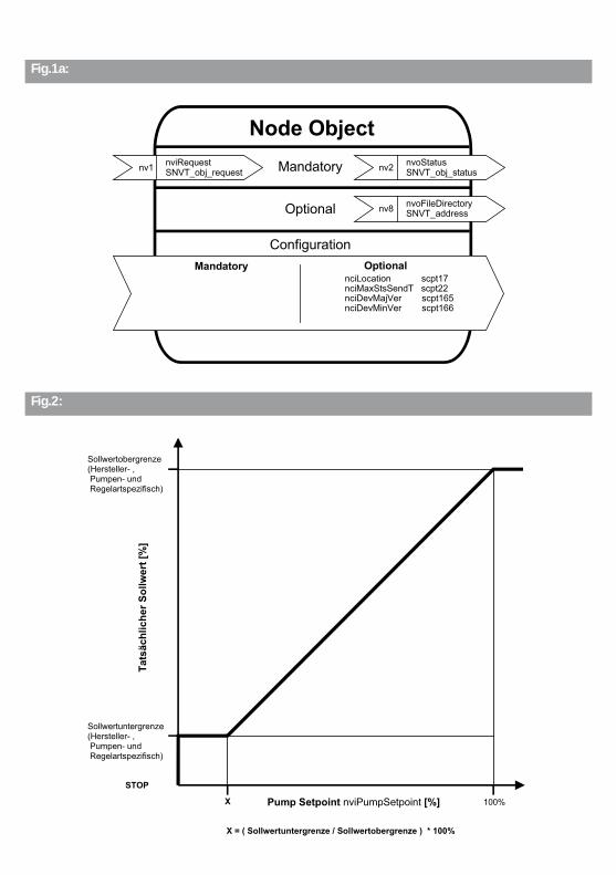
Fig.1a:
nv1 nviRequestSNVT_obj_request nv2 nvoStatus
SNVT_obj_status
nv8 nvoFileDirectorySNVT_address
Mandatory
Configuration
Optional
Node Object
Mandatory Optional
nciMaxStsSendT scpt22nciDevMajVer scpt165nciDevMinVer scpt166
nciLocation scpt17
Fig.2:
Sollwertobergrenze(Hersteller- , Pumpen- und Regelartspezifisch)
Tats
ächl
iche
r Sol
lwer
t [%
]
STOP
X 100%Pump Setpoint nviPumpSetpoint [%]
Sollwertuntergrenze(Hersteller- , Pumpen- und Regelartspezifisch)
X = ( Sollwertuntergrenze / Sollwertobergrenze ) * 100%
Fig.1b:
nv1 nviPumpSetpointSNVT_switch
nv2 nviPumpOpModeSNVT_hvac_mode
nv3 nvoPumpCapacitySNVT_lev_percent
nv4 nvoEffOpModeSNVT_hvac_mode
nv5 nvoControlModeSNVT_dev_c_mode
nv13 nvoPumpStatusSNVT_dev_statusnv6 nviPumpOvdStop
SNVT_switch
nv7 nviOvdSpeedSNVT_lev_percent
nv8 nviOvdPressSNVT_press
nv10 nviRemotePressSNVT_press
nv12 nviRemoteTempSNVT_temp_p
nv14 nvoPressureSNVT_press
nv15 nvoFlowSNVT_flow_p
nv16 nvoSpeedSNVT_rpm
nv17 nvoPumpOverrideSNVT_switch
nv18 nvoRuntimeSNVT_time_hour
nv19 nvoPumpFaultSNVT_dev_fault
nv20 nvoMaintenanceSNVT_dev_maint
nv21 nvoFluidTempSNVT_temp_p
nv22 nvoPowerSNVT_power
nv23 nvoPowerKiloSNVT_power_kilo
nv24 nvoEnergyConsumSNVT_elec_kwh
Mandatory
Optional
Configuration
Pump Controller Object
Mandatory OptionalnciSndHrtBt scpt49nroPumpChar scpt233
nciRcvHrtBt scpt48nciMinOutTm scpt52
nciControlMode scpt238nciRemMinPress scpt239nciRemMaxPress scpt240nciRemMinTemp scpt243nciRemMaxTemp scpt244
nciObjMajVer scpt167nciObjMinVer scpt168
nciPressTemp ucptnciSetpPreset scpt213nciBusCommandTm ucpt
nv38 nvoCurrentErrorMSNVT_count
nv39 nvoCurrentErrorSSNVT_count
nv40 nvoPumpStatusMSNVT_dev_status
nv41 nvoPumpStatusSSNVT_dev_status
nv42 nvoPumpTypeSNVT_count
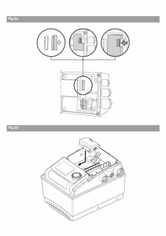
Fig.3a:
L N
S
SM
Ach
tung
Achtung OptionIF-Modul
NetzspannungAttentionMainsVoltage
Atte
ntio
n1
- 230
V
!
Fig.3b:
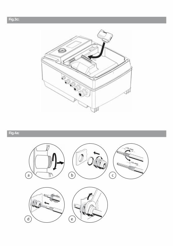
Fig.3c:
Fig.4a:
~15 mm
~15 mm
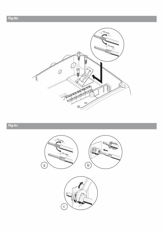
Fig.4b:
~15 mm
~15 mm
Fig.4c:
~15 mm
~15 mm
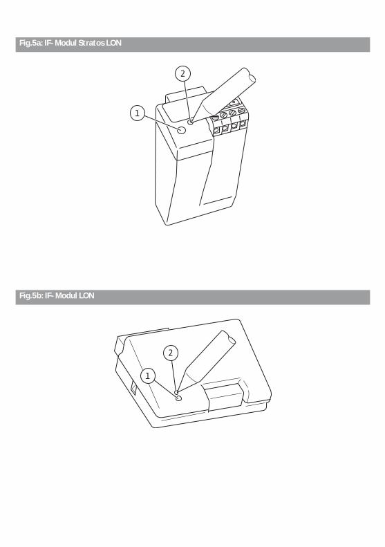
Fig.5a: IF-Modul Stratos LON
Fig.5b: IF-Modul LON
English
44 WILO SE 03/2016
Installation and operating instructions1 General
1.1 About this documentThe language of the original operating instructions is German. All other lan-guages of these instructions are translations of the original operating instruc-tions.These installation and operating instructions are an integral part of the product. They must be kept readily available at the place where the product is installed. Strict adherence to these instructions is a precondition for the proper use and correct operation of the product.These installation and operating instructions correspond to the relevant version of the product and the underlying safety regulations and standards valid at the time of going to print.These Installation and operating instructions are intended as supplement to the Installation and operating instructions for the pumps connected to the LON bus.
2 SafetyThese instructions contain important information which must be followed when installing and operating the pump. These operating instructions must therefore be read before assembly and commissioning by the installer and the responsible operator.
2.1 Indication of instructions in the operating instructions
Symbols:General danger symbol
Danger due to electrical voltage
NOTE: ...
Signal words:DANGER!Acutely dangerous situation.Non-observance will result in death or serious injuries.
WARNING!The user may suffer (serious) injuries. 'Warning' implies that (serious) injury to persons is likely if this information is disregarded.
Installation and operating instructions Wilo-Control IF-module LON / IF-module Stratos LON 45
English
CAUTION!There is a risk of damaging the pump/unit. 'Caution' implies that damage to the product is possible if this information is disregarded.
NOTE: Useful information on using the product. It also draws attention to potential problems.
Information that appears directly on the product, such as• Direction of rotation arrow,• Connection marks,• Rating plate,• Warning sticker
must be strictly complied with and kept in legible condition.
2.2 Personnel qualificationsThe installation, operating and maintenance personnel must have the appropri-ate qualifications for this work. Area of responsibility, terms of reference and monitoring of the personnel are to be ensured by the operator. If the personnel are not in possession of the necessary knowledge, they are to be trained and instructed. This can be accomplished if necessary by the manufacturer of the product at the request of the operator.
2.3 Danger in the event of non-observance of the safety instructionsNon-observance of the safety instructions can result in risk of injury to per-sons and damage to the environment and the product/unit. Non-observance of the safety instructions results in the loss of any claims to damages.In detail, non-observance can, for example, result in the following risks:
• Danger to persons due to electrical, mechanical and bacteriological factors• Damage to the environment due to leakage of hazardous materials• Property damage• Failure of important product/unit functions• Failure of required maintenance and repair procedures
2.4 Safety consciousness on the jobThe safety instructions included in these installation and operating instructions, the existing national regulations for accident prevention together with any internal working, operating and safety regulations of the operator are to be complied with.
English
46 WILO SE 03/2016
2.5 Safety instructions for the operatorThis appliance is not intended for use by persons (including children) with reduced physical, sensory or mental capabilities, or lack of experience and knowledge, unless they have been given supervision or instruction concerning use of the appliance by a person responsible for their safety. Children should be supervised to ensure that they do not play with the appli-ance.
• If hot or cold components on the product/the unit lead to hazards, measures must be taken onsite to guard them against touching.
• Guards protecting against touching moving components (such as the coupling) must not be removed whilst the product is in operation.
• Leakages (e.g. from a shaft seal) of hazardous fluids (e.g. explosive, toxic or hot) must be conveyed away so that no danger to persons or to the environment arises. National statutory provisions are to be complied with.
• Highly flammable materials are always to be kept at a safe distance from the product.
• Danger from electrical current must be eliminated. Local directives or general directives [e.g. IEC, VDE etc.] and instructions from local energy supply compa-nies must be adhered to.
2.6 Safety instructions for installation and maintenance workThe operator must ensure that all installation and maintenance work is carried out by authorised and qualified personnel who are sufficiently informed from their own detailed study of the operating instructions.Work on the product/unit may only be carried out when the system is at a stand-still. It is mandatory that the procedure described in the installation and operat-ing instructions for shutting down the product/unit be complied with.Immediately on conclusion of the work, all safety and protective devices must be put back in position and/or recommissioned.
2.7 Unauthorised modification and manufacture of spare partsUnauthorised modification and manufacture of spare parts will impair the safety of the product/personnel and will make void the manufacturer’s declarations regarding safety.Modifications to the product are only permissible after consultation with the manufacturer. Original spare parts and accessories authorised by the manufac-turer ensure safety. The use of other parts will absolve us of liability for conse-quential events.
2.8 Improper useThe operating safety of the supplied product is only guaranteed for con-ventional use in accordance with Section 4 of the operating instructions. The limits values must on no account fall under or exceed those specified in the catalogue/data sheet.
Installation and operating instructions Wilo-Control IF-module LON / IF-module Stratos LON 47
English
3 Transport and interim storageInspect the pump/system for transport damage immediately upon arrival. Any transport damage found must be reported to the carrier within the prescribed periods.CAUTION! Risk of damage to the IF-module!Risk of damage due to improper handling during transport and storage.
• The IF-modules should be protected against humidity, frost and mechanical damage during transport and temporary storage.
• They must not be exposed to temperatures outside the range of - 10 °C to + 70 °C.
4 Intended use The IF-module LON/Stratos LON is used to connect electronically controlled glandless or glanded pumps to a LON. The pump can be preset with setpoints, operating modes and data from external sensors. Current operating data and fault signals can be transferred from the pump via the LON bus.At the same time the IF-module LON/Stratos LON allows two pumps to be connected to form a double pump via an additional DP interface. This interface is a separate device. It is not a LON-based interface. That is why the LON bus for the double pump interface is not put under strain and the slave pump can be equipped with an inexpensive IF-module PLR.
English
48 WILO SE 03/2016
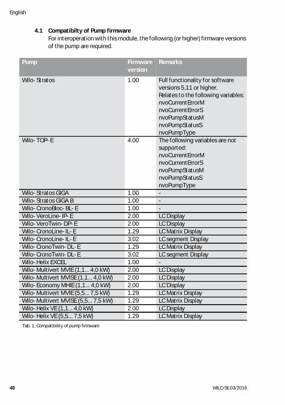
4.1 Compatibilty of Pump firmwareFor interoperation with this module, the following (or higher) firmware versions of the pump are required.
Pump Firmware version
Remarks
Wilo-Stratos 1.00 Full functionality for software versions 5.11 or higher.Relates to the following variables:nvoCurrentErrorMnvoCurrentErrorSnvoPumpStatusMnvoPumpStatusSnvoPumpType
Wilo-TOP-E 4.00 The following variables are not supported:nvoCurrentErrorMnvoCurrentErrorSnvoPumpStatusMnvoPumpStatusSnvoPumpType
Wilo-Stratos GIGA 1.00 -Wilo-Stratos GIGA B 1.00 -Wilo-CronoBloc-BL-E 1.00 -Wilo-VeroLine-IP-E 2.00 LC DisplayWilo-VeroTwin-DP-E 2.00 LC DisplayWilo-CronoLine-IL-E 1.29 LC Matrix DisplayWilo-CronoLine-IL-E 3.02 LC segment DisplayWilo-CronoTwin-DL-E 1.29 LC Matrix DisplayWilo-CronoTwin-DL-E 3.02 LC segment DisplayWilo-Helix EXCEL 1.00 -Wilo-Multivert MVIE (1,1... 4,0 kW) 2.00 LC DisplayWilo-Multivert MVISE (1,1... 4,0 kW) 2.00 LC DisplayWilo-Economy MHIE (1,1... 4,0 kW) 2.00 LC DisplayWilo-Multivert MVIE (5,5... 7,5 kW) 1.29 LC Matrix DisplayWilo-Multivert MVISE (5,5... 7,5 kW) 1.29 LC Matrix DisplayWilo-Helix VE (1,1... 4,0 kW) 2.00 LC DisplayWilo-Helix VE (5,5... 7,5 kW) 1.29 LC Matrix Display
Tab. 1: Compatibility of pump firmware
Installation and operating instructions Wilo-Control IF-module LON / IF-module Stratos LON 49
English
5 Product information
5.1 Type key
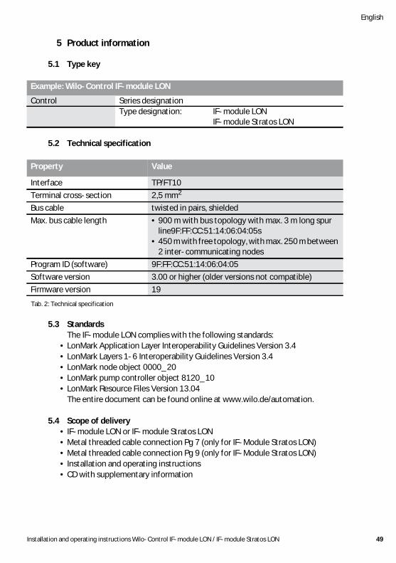
5.2 Technical specification
5.3 StandardsThe IF-module LON complies with the following standards:
• LonMark Application Layer Interoperability Guidelines Version 3.4• LonMark Layers 1-6 Interoperability Guidelines Version 3.4• LonMark node object 0000_20• LonMark pump controller object 8120_10• LonMark Resource Files Version 13.04
The entire document can be found online at www.wilo.de/automation.
5.4 Scope of delivery • IF-module LON or IF-module Stratos LON• Metal threaded cable connection Pg 7 (only for IF-Module Stratos LON)• Metal threaded cable connection Pg 9 (only for IF-Module Stratos LON)• Installation and operating instructions• CD with supplementary information
Example: Wilo-Control IF-module LON
Control Series designationType designation: IF-module LON
IF-module Stratos LON
Property Value
Interface TP/FT10Terminal cross-section 2,5 mm2
Bus cable twisted in pairs, shieldedMax. bus cable length • 900 m with bus topology with max. 3 m long spur
line9F:FF:CC:51:14:06:04:05s • 450 m with free topology, with max. 250 m between
2 inter-communicating nodesProgram ID (software) 9F:FF:CC:51:14:06:04:05Software version 3.00 or higher (older versions not compatible)Firmware version 19
Tab. 2: Technical specification
English
50 WILO SE 03/2016
5.4.1 Delivery conditionAccording to the LonMark Application Layer Interoperability Guidelines, the IF-module LON is delivered in “application unconfigured” condition. In this condition, the IF-module LON can be addressed via the LON bus, but the application which normally establishes the communication with the pump is not yet in operation. There is therefore no activity yet after connecting the IF-module LON and switching on the power supply of the pump.This is signalized by flashing of the green LED.
6 Description and function
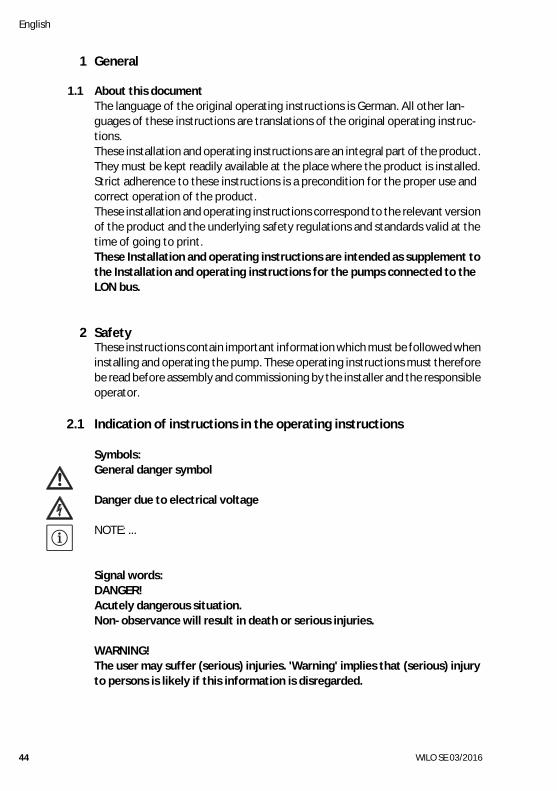
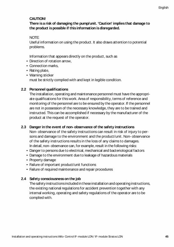
6.1 Description of the objectsTwo objects, the node object and pump object, are implemented in the IF-module LON. The node object is used to control individual objects within the node; errors which occur in the individual objects are also indicated centrally here.Fig. 1a shows the node object with the corresponding network variables, Fig. 1b shows the pump controller object with the corresponding network variables.NOTE:
• Double pumps should always be equipped with the integrated double pump management.
• At double pumps, the IF-module LON is connected to the master.• If the integrated double pump management is not used for double pumps,
the two drives should be treated as two separate individual pumps. In this case, two LON IF modules are necessary.
• The control functions apply to the double pump as entire unit.
Installation and operating instructions Wilo-Control IF-module LON / IF-module Stratos LON 51
English
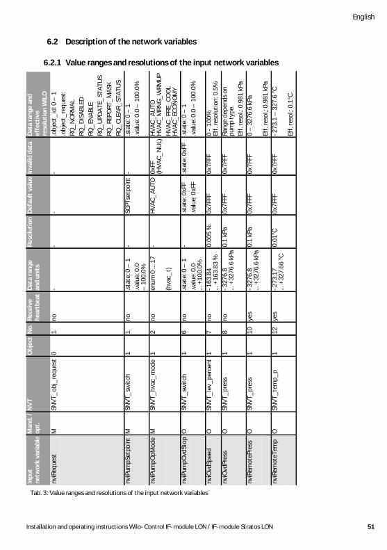
6.2 Description of the network variables
6.2.1 Value ranges and resolutions of the input network variables
Dat
a ra
nge
and
effe
ctiv
ere
solu
tion
WIL
O.o
bjec
t_id
: 0 –
1.o
bjec
t_re
ques
t:RQ
_N
ORM
AL
RQ_
DIS
ABL
EDRQ
_EN
ABL
ERQ
_U
PDA
TE_
STA
TUS
RQ_
REPO
RT_
MA
SKRQ
_CL
EAR_
STA
TUS
.sta
te: 0
– 1
.val
ue: 0
.0 –
100
.0%
HVA
C_A
UTO
HVA
C_M
RNG
_W
RMU
PH
VAC_
PRE_
COO
LH
VAC_
ECO
NO
MY
.sta
te: 0
– 1
.val
ue: 0
.0 –
100
.0%
0 -
100%
Eff.
reso
lutio
n: 0
.5%
Rang
e de
pend
s on
pum
p ty
pe.
Eff.
reso
l.: 0
.981
kPa
0 –
327
6.6
kPa
Eff.
reso
l.: 0
.981
kPa
-273
.1 –
327
.6 °C
Eff.
reso
l.: 0
.1°C
Inva
lid d
ata
- - 0xFF
(HVA
C_N
UL)
.sta
te: 0
xFF
0x7F
FF
0x7F
FF
0x7F
FF
0x7F
FF
Def
ault
val
ue
- SCPT
setp
oint
HVA
C_A
UTO
.sta
te: 0
xFF
.val
ue: 0
xFF
0x7F
FF
0x7F
FF
0x7F
FF
0x7F
FF
Reso
luti
on
- - - - 0.00
5 %
0.1
kPa
0.1
kPa
0.01
°C
Dat
a ra
nge
and
unit
s
- .sta
te: 0
– 1
.val
ue: 0
.0
– 1
00.0
%en
um 0
... 1
7
(hva
c_t)
.sta
te: 0
– 1
.val
ue: 0
.0
... +
100.
0%-1
63.8
4 ...
+16
3.83
%-3
276.
8 ...
+32
76.6
kPa
-327
6.8
... +
3276
.6 k
Pa
-273
.17
... +
327.
66 °C
Rece
ive
hear
tbea
t
no no no no no no yes
yes
No.
1 1 2 6 7 8 10 12
Obj
ect
0 1 1 1 1 1 1 1
NV
T
SNVT
_ob
j_re
ques
t
SNVT
_sw
itch
SNVT
_hv
ac_
mod
e
SNVT
_sw
itch
SNVT
_le
v_pe
rcen
t
SNVT
_pr
ess
SNVT
_pr
ess
SNVT
_te
mp_
p
Man
d. /
opt.
M M M O O O O O
Inpu
tne
twor
k va
riab
le
nviR
eque
st
nviP
umpS
etpo
int
nviP
umpO
pMod
e
nviP
umpO
vdSt
op
nviO
vdSp
eed
nviO
vdPr
ess
nviR
emot
ePre
ss
nviR
emot
eTem
p
Tab. 3: Value ranges and resolutions of the input network variables
English
52 WILO SE 03/2016
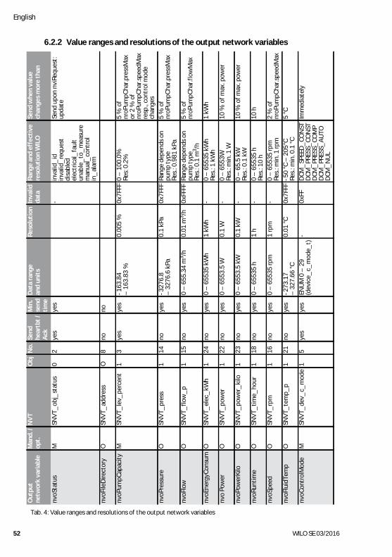
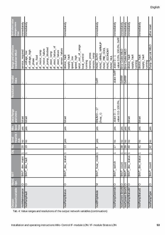
6.2.2 Value ranges and resolutions of the output network variables
Send
whe
n va
lue
chan
ges
mor
e th
an
Send
upo
n nv
iReq
uest
: up
date
5 %
of
nroP
umpC
har.p
ress
Max
or 2
% o
f nr
oPum
pCha
r.spe
edM
axre
sp.,
cont
rol m
ode
chan
ges
5 %
of
nroP
umpC
har.p
ress
Max
5 %
of
nroP
umpC
har.f
low
Max
1 kW
h
10 %
of m
ax. p
ower
10 %
of m
ax. p
ower
10 h
2 %
of
nroP
umpC
har.s
peed
Max
5 °C
Imm
edia
tely
Rang
e an
d ef
fect
ive
reso
luti
on W
ILO
inva
lid_
idin
valid
_re
ques
tdi
sabl
edel
ectr
ical
_fa
ult
unab
le_
to_
mea
sure
man
ual_
cont
rol
in_
alar
m
0 –
100
.0%
Res:
0.2
%
Rang
e de
pend
s on
pum
p ty
peRe
s.: 0
.981
kPa
Rang
e de
pend
s on
pum
p ty
peRe
s.: 0
.1 m
3 /h0
– 6
5535
kW
hRe
s.: 1
kW
h0
– 6
553W
Res.
: min
. 1 W
0 –
65.
5 kW
Res.
: 0.1
kW
0 –
655
35 h
Res.
: 10
h0
– 6
5535
rpm
Res.
: min
. 1 rp
m-5
0 °C
– 2
05°C
Res.
: min
. 0.1
°CD
CM_
SPEE
D_
CON
STD
CM_
PRES
S_CO
NST
DCM
_PR
ESS_
COM
PD
CM_
PRES
S_A
UTO
DCM
_N
UL
Inva
lidda
ta
- 0x7F
FF
0x7F
FF
0xFF
FF
- - - - - 0x7F
FF
0xFF
Reso
luti
on
0.00
5 %
0.1
kPa
0.01
m3 /h
1 kW
h
0.1
W
0.1
kW
1 h
1 rp
m
0.01
°C
-
Dat
a ra
nge
and
unit
s
-163
.84
– 1
63.8
3 %
-327
6.8
– 3
276.
6 kP
a
0 –
655
.34
m3 /h
0 –
655
35 k
Wh
0 –
655
3.5
W
0 –
655
3.5
kW
0 –
655
35 h
0 –
655
35 rp
m
-273
.17
– 3
27.6
6 °C
ENU
M 0
– 2
9(d
evic
e_c_
mod
e_t)
Min
.se
ndti
me
yes
no yes
yes
yes
yes
yes
yes
yes
yes
yes
yes
Send
hear
tbt
/A
ckye
s
no yes
no no no no no no no no yes
No.
2 8 3 14 15 24 22 23 18 16 21 5
Obj
0 O 1 1 1 1 1 1 1 1 1 1
NV
T
SNVT
_ob
j_st
atus
SNVT
_ad
dres
s
SNVT
_le
v_pe
rcen
t
SNVT
_pr
ess
SNVT
_flo
w_
p
SNVT
_el
ec_
kWh
SNVT
_po
wer
SNVT
_po
wer
_ki
lo
SNVT
_tim
e_ho
ur
SNVT
_rp
m
SNVT
_te
mp_
p
SNVT
_de
v_c_
mod
e
Man
d. /
opt.
M O M O O O O O O O O M
Out
put
netw
ork
vari
able
nvoS
tatu
s
nvoF
ileD
irect
ory
nvoP
umpC
apac
ity
nvoP
ress
ure
nvoF
low
nvoE
nerg
yCon
sum
nvo
Pow
er
nvoP
ower
Kilo
nvoR
untim
e
nvoS
peed
nvoF
luid
Tem
p
nvoC
ontr
olM
ode
Tab. 4: Value ranges and resolutions of the output network variables
Installation and operating instructions Wilo-Control IF-module LON / IF-module Stratos LON 53
English
Send
whe
n va
lue
chan
ges
mor
e
than
imm
edia
tely
imm
edia
tely
imm
edia
tely
imm
edia
tely
imm
edia
tely
imm
edia
tely
imm
edia
tely
imm
edia
tely
imm
edia
tely
afte
r res
et
Rang
e an
d ef
fect
ive
reso
luti
on W
ILO
serv
ice_
requ
ired
sf_
volta
ge_
low
sf_
volta
ge_
high
sf_
phas
esf
_no
_flu
iddf
_m
otor
_te
mp
df_
mot
or_
failu
redf
_pu
mp_
bloc
ked
df_
elec
t_te
mp
df_
elec
t_fa
ilure
_nf
df_
elec
t_fa
ilure
df_
sens
or_
failu
rede
vice
_fa
ult
supp
ly_
faul
tsp
eed_
low
spee
d_hi
ghse
tpt_
out_
of_
rang
elo
cal_
cont
rol
runn
ing
rem
ote_
pres
sre
mot
e_te
mp
HVA
C_A
UTO
HVA
C_M
RNG
_W
RMU
PH
VAC_
PRE_
COO
LH
VAC_
ECO
NO
MY
HVA
C_N
UL
.sta
te: 0
– 1
.val
ue: 0
.0%
, 100
.0%
, 0xF
FEr
ror C
odes
WIL
OEr
ror C
odes
WIL
Ode
vice
_fa
ult
supp
ly_
faul
tru
nnin
gde
vice
_fa
ult
supp
ly_
faul
tru
nnin
gPu
mp
Type
Lis
t WIL
O
Inva
lid
Dat
a
- - - 0xFF
.sta
te: 0
xFF
0xFF
FF0x
FFFF
- - -
Reso
luti
on
- - - - - - - - - -
Dat
a Ra
nge
and
Uni
ts
bits
etbi
tset
bits
et
ENU
M 0
– 1
7(h
vac_
t)
.sta
te: 0
– 1
.val
ue: 0
.0-1
00.0
%,
bits
et
bits
et
Min
.Se
nd
Tim
eye
sye
s
yes
yes
yes
yes
yes
yes
yes
yes
Send
H
eart
bt /
Ack
no no yes
yes
no no no no no no
No.
20 19 13 4 17 38 39 40 41 42
Obj
1 1 1 1 1 1 1 1 1 1
NV
T
SNVT
_de
v_m
aint
SNVT
_de
v_fa
ult
SNVT
_de
v_st
atus
SNVT
_hv
ac_
mod
e
SNVT
_sw
itch
SNVT
_co
unt
SNVT
_co
unt
SNVT
_de
v_st
atus
SNVT
_de
v_st
atus
SNVT
_co
unt
Man
d.O
pt.
O O O M O O O O O O
Out
put-
Net
wor
kvar
iabl
e
nvoM
aint
enan
cenv
oPum
pFau
lt
nvoP
umpS
tatu
s
nvoE
ffO
pMod
e
nvoP
umpO
verr
ide
nvoC
urre
nt E
rror
Mnv
oCur
rent
Err
orS
nvoP
umpS
tatu
sM
nvoP
umpS
tatu
sS
nvoP
umpT
ype
Tab. 4: Value ranges and resolutions of the output network variables (continuation)
English
54 WILO SE 03/2016
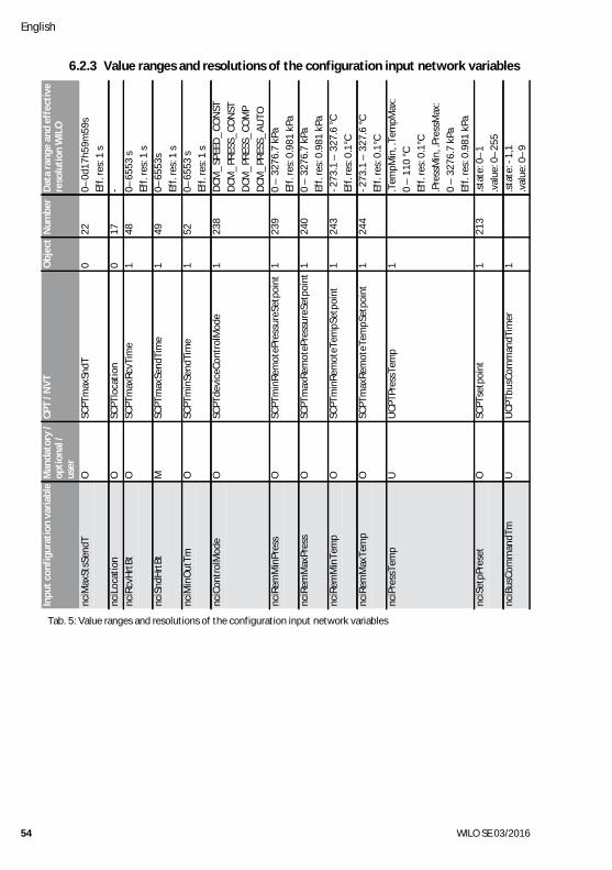
6.2.3 Value ranges and resolutions of the configuration input network variables
Dat
a ra
nge
and
effe
ctiv
ere
solu
tion
WIL
O
0–0d
17h5
9m59
sEf
f. re
s: 1
s- 0–
6553
sEf
f. re
s: 1
s0–
6553
sEf
f. re
s: 1
s0–
6553
sEf
f. re
s: 1
sD
CM_
SPEE
D_
CON
STD
CM_
PRES
S_CO
NST
DCM
_PR
ESS_
COM
PD
CM_
PRES
S_A
UTO
0 –
327
6.7
kPa
Eff.
res:
0.9
81 k
Pa0
– 3
276.
7 kP
aEf
f. re
s: 0
.981
kPa
-273
.1 –
327
.6 °C
Eff.
res:
0.1
°C-2
73.1
– 3
27.6
°CEf
f. re
s: 0
.1°C
.Tem
pMin
, .Te
mpM
ax:
0 –
110
°CEf
f. re
s: 0
.1°C
.Pre
ssM
in, .
Pres
sMax
:0
– 3
276.
7 kP
aEf
f. re
s: 0
.981
kPa
.sta
te: 0
–1
.val
ue: 0
–25
5.s
tate
: -1,
1.v
alue
: 0–
9
Num
ber
22 17 48 49 52 238
239
240
243
244
213
Obj
ect
0 0 1 1 1 1 1 1 1 1 1 1 1
CPT
/ NV
T
SCPT
max
SndT
SCPT
loca
tion
SCPT
max
RcvT
ime
SCPT
max
Send
Tim
e
SCPT
min
Send
Tim
e
SCPT
devi
ceCo
ntro
lMod
e
SCPT
min
Rem
oteP
ress
ureS
etpo
int
SCPT
max
Rem
oteP
ress
ureS
etpo
int
SCPT
min
Rem
oteT
empS
etpo
int
SCPT
max
Rem
oteT
empS
etpo
int
UCP
TPre
ssTe
mp
SCPT
setp
oint
UCP
Tbus
Com
man
dTim
er
Man
dato
ry /
opti
onal
/ us
erO O O M O O O O O O U O U
Inpu
t co
nfig
urat
ion
vari
able
nciM
axSt
sSen
dT
nciL
ocat
ion
nciR
cvH
rtBt
nciS
ndH
rtBt
nciM
inO
utTm
nciC
ontr
olM
ode
nciR
emM
inPr
ess
nciR
emM
axPr
ess
nciR
emM
inTe
mp
nciR
emM
axTe
mp
nciP
ress
Tem
p
nciS
etpP
rese
t
nciB
usCo
mm
andT
m
Tab. 5: Value ranges and resolutions of the configuration input network variables
Installation and operating instructions Wilo-Control IF-module LON / IF-module Stratos LON 55
English
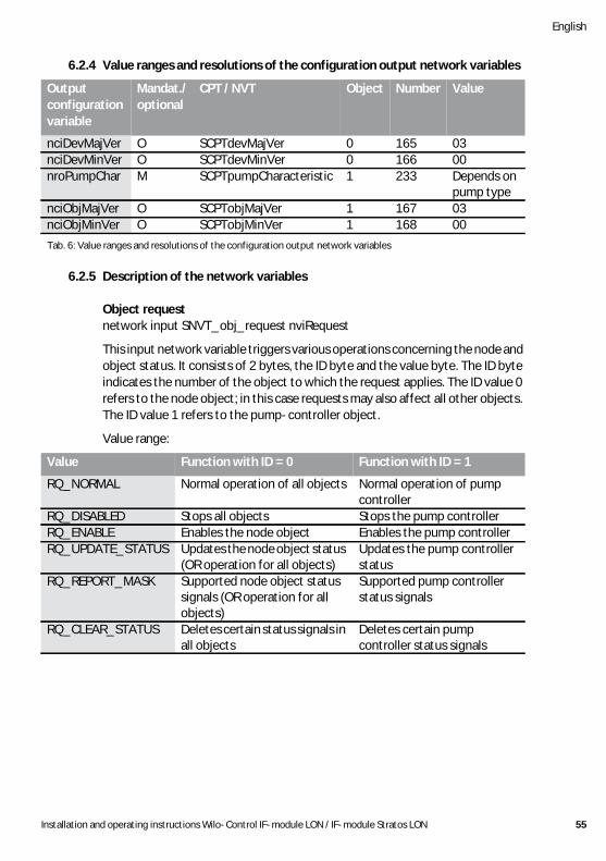
6.2.4 Value ranges and resolutions of the configuration output network variables
6.2.5 Description of the network variables
Object requestnetwork input SNVT_obj_request nviRequest
This input network variable triggers various operations concerning the node and object status. It consists of 2 bytes, the ID byte and the value byte. The ID byte indicates the number of the object to which the request applies. The ID value 0 refers to the node object; in this case requests may also affect all other objects. The ID value 1 refers to the pump-controller object.
Value range:
Outputconfigurationvariable
Mandat./optional
CPT / NVT Object Number Value
nciDevMajVer O SCPTdevMajVer 0 165 03nciDevMinVer O SCPTdevMinVer 0 166 00nroPumpChar M SCPTpumpCharacteristic 1 233 Depends on
pump typenciObjMajVer O SCPTobjMajVer 1 167 03nciObjMinVer O SCPTobjMinVer 1 168 00
Tab. 6: Value ranges and resolutions of the configuration output network variables
Value Function with ID = 0 Function with ID = 1
RQ_NORMAL Normal operation of all objects Normal operation of pump controller
RQ_DISABLED Stops all objects Stops the pump controllerRQ_ENABLE Enables the node object Enables the pump controllerRQ_UPDATE_STATUS Updates the node object status
(OR operation for all objects)Updates the pump controller status
RQ_REPORT_MASK Supported node object status signals (OR operation for all objects)
Supported pump controller status signals
RQ_CLEAR_STATUS Deletes certain status signals in all objects
Deletes certain pump controller status signals
English
56 WILO SE 03/2016
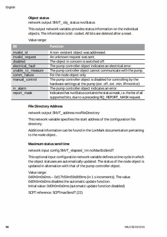
Object statusnetwork output SNVT_obj_status nvoStatus
This output network variable provides status information on the individual objects. The information is bit-coded. All bits are deleted after a reset.
Value range:
File Directory Address
network output SNVT_address nvoFileDirectory
This network variable specifies the start address of the configuration file directory.
Additional information can be found in the LonMark documentation pertaining to the node object..
Maximum status send time
network input config SNVT_elapsed_tm nciMaxStsSendT
This optional input configuration network variable defines a time cycle in which the object statuses are automatically updated. The status of the node object is updated in alternation with that of the pump controller object.
Value range:0d0h0m0s0ms – 0d17h59m59s999ms (in 1 s increments). The value 0d0h0m0s0ms disables the automatic update function.Initial value: 0d0h0m0s0ms (automatic update function disabled)
SCPT reference: SCPTmaxSendT (22)
Bit Function
invalid_id A non-existent object was addressed.invalid_request An unknown request was sent.disabled The object in concern is switched off.electrical_fault The pump controller object indicates an electrical error.unable_to_measure The pump controller object cannot communicate with the pump.comm_failure For the node object onlymanual_control The pump controller object is disabled for controlling by the
hardware settings at the pump (ext. off, ext. min, IR monitor)in_alarm The pump controller object indicates an error.report_mask Indicates that nvoStatus contains the status mask, i.e. the list of all
supported bits, due to a preceding RQ_REPORT_MASK request.
Installation and operating instructions Wilo-Control IF-module LON / IF-module Stratos LON 57
English
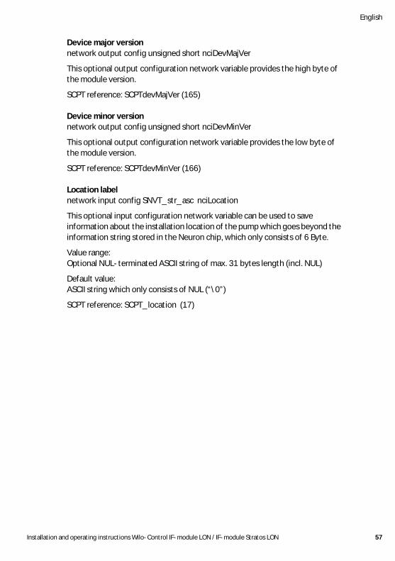
Device major versionnetwork output config unsigned short nciDevMajVer
This optional output configuration network variable provides the high byte of the module version.
SCPT reference: SCPTdevMajVer (165)
Device minor versionnetwork output config unsigned short nciDevMinVer
This optional output configuration network variable provides the low byte of the module version.
SCPT reference: SCPTdevMinVer (166)
Location labelnetwork input config SNVT_str_asc nciLocation
This optional input configuration network variable can be used to save information about the installation location of the pump which goes beyond the information string stored in the Neuron chip, which only consists of 6 Byte.
Value range:Optional NUL-terminated ASCII string of max. 31 bytes length (incl. NUL)
Default value:ASCII string which only consists of NUL (“\0”)
SCPT reference: SCPT_location (17)
English
58 WILO SE 03/2016
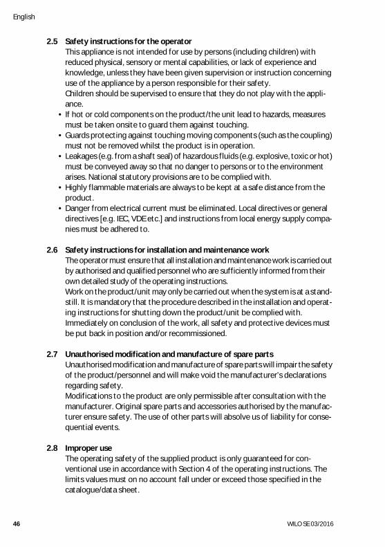
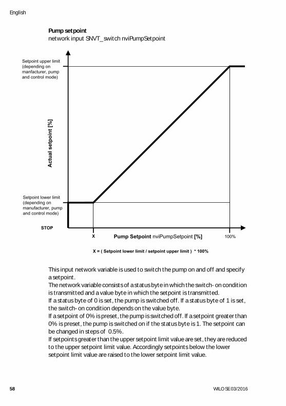
Pump setpointnetwork input SNVT_switch nviPumpSetpoint
This input network variable is used to switch the pump on and off and specify a setpoint.The network variable consists of a status byte in which the switch-on condition is transmitted and a value byte in which the setpoint is transmitted.If a status byte of 0 is set, the pump is switched off. If a status byte of 1 is set, the switch-on condition depends on the value byte.If a setpoint of 0% is preset, the pump is switched off. If a setpoint greater than 0% is preset, the pump is switched on if the status byte is 1. The setpoint can be changed in steps of 0.5%.If setpoints greater than the upper setpoint limit value are set, they are reduced to the upper setpoint limit value. Accordingly setpoints below the lower setpoint limit value are raised to the lower setpoint limit value.
Setpoint upper limit(depending onmanfacturer, pumpand control mode)
Act
ual s
etpo
int [
%]
STOP
X 100%Pump Setpoint nviPumpSetpoint [%]
Setpoint lower limit(depending onmanufacturer, pumpand control mode)
X = ( Setpoint lower limit / setpoint upper limit ) * 100%
Installation and operating instructions Wilo-Control IF-module LON / IF-module Stratos LON 59
English
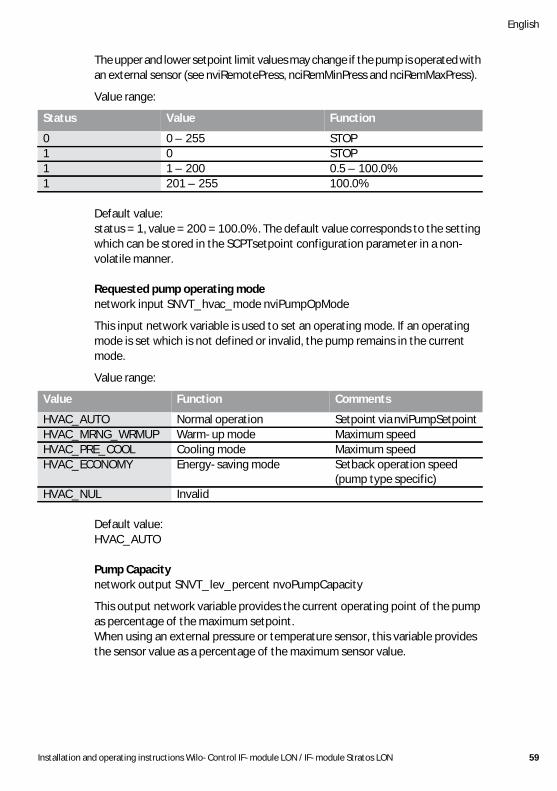
The upper and lower setpoint limit values may change if the pump is operated with an external sensor (see nviRemotePress, nciRemMinPress and nciRemMaxPress).
Value range:
Default value: status = 1, value = 200 = 100.0%. The default value corresponds to the setting which can be stored in the SCPTsetpoint configuration parameter in a non-volatile manner.
Requested pump operating modenetwork input SNVT_hvac_mode nviPumpOpMode
This input network variable is used to set an operating mode. If an operating mode is set which is not defined or invalid, the pump remains in the current mode.
Value range:
Default value: HVAC_AUTO
Pump Capacitynetwork output SNVT_lev_percent nvoPumpCapacity
This output network variable provides the current operating point of the pump as percentage of the maximum setpoint.When using an external pressure or temperature sensor, this variable provides the sensor value as a percentage of the maximum sensor value.
Status Value Function
0 0 – 255 STOP1 0 STOP1 1 – 200 0.5 – 100.0%1 201 – 255 100.0%
Value Function Comments
HVAC_AUTO Normal operation Setpoint via nviPumpSetpointHVAC_MRNG_WRMUP Warm-up mode Maximum speedHVAC_PRE_COOL Cooling mode Maximum speedHVAC_ECONOMY Energy-saving mode Setback operation speed
(pump type specific)HVAC_NUL Invalid
English
60 WILO SE 03/2016
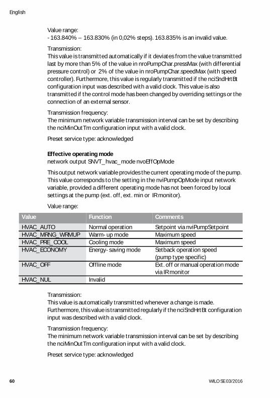
Value range:-163.840% – 163.830% (in 0,02% steps). 163.835% is an invalid value.
Transmission:This value is transmitted automatically if it deviates from the value transmitted last by more than 5% of the value in nroPumpChar.pressMax (with differential pressure control) or 2% of the value in nroPumpChar.speedMax (with speed controller). Furthermore, this value is regularly transmitted if the nciSndHrtBt configuration input was described with a valid clock. This value is also transmitted if the control mode has been changed by overriding settings or the connection of an external sensor.
Transmission frequency:The minimum network variable transmission interval can be set by describing the nciMinOutTm configuration input with a valid clock.
Preset service type: acknowledged
Effective operating modenetwork output SNVT_hvac_mode nvoEffOpMode
This output network variable provides the current operating mode of the pump. This value corresponds to the setting in the nviPumpOpMode input network variable, provided a different operating mode has not been forced by local settings at the pump (ext. off, ext. min or IR monitor).
Value range:
Transmission:This value is automatically transmitted whenever a change is made.Furthermore, this value is transmitted regularly if the nciSndHrtBt configuration input was described with a valid clock.
Transmission frequency:The minimum network variable transmission interval can be set by describing the nciMinOutTm configuration input with a valid clock.
Preset service type: acknowledged
Value Function Comments
HVAC_AUTO Normal operation Setpoint via nviPumpSetpointHVAC_MRNG_WRMUP Warm-up mode Maximum speedHVAC_PRE_COOL Cooling mode Maximum speedHVAC_ECONOMY Energy-saving mode Setback operation speed
(pump type specific)HVAC_OFF Offline mode Ext. off or manual operation mode
via IR monitorHVAC_NUL Invalid
Installation and operating instructions Wilo-Control IF-module LON / IF-module Stratos LON 61
English
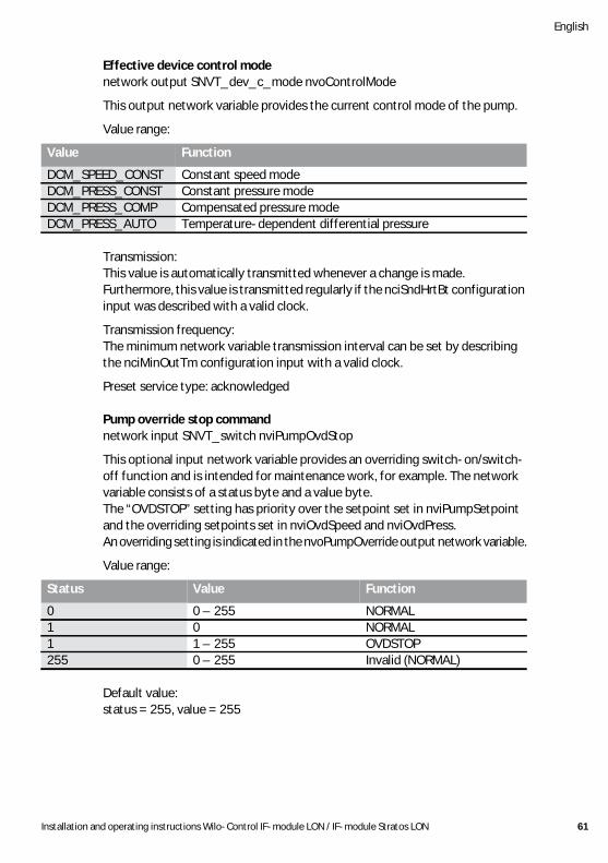
Effective device control modenetwork output SNVT_dev_c_mode nvoControlMode
This output network variable provides the current control mode of the pump.
Value range:
Transmission:This value is automatically transmitted whenever a change is made.Furthermore, this value is transmitted regularly if the nciSndHrtBt configuration input was described with a valid clock.
Transmission frequency:The minimum network variable transmission interval can be set by describing the nciMinOutTm configuration input with a valid clock.
Preset service type: acknowledged
Pump override stop commandnetwork input SNVT_switch nviPumpOvdStop
This optional input network variable provides an overriding switch-on/switch-off function and is intended for maintenance work, for example. The network variable consists of a status byte and a value byte.The “OVDSTOP” setting has priority over the setpoint set in nviPumpSetpoint and the overriding setpoints set in nviOvdSpeed and nviOvdPress.An overriding setting is indicated in the nvoPumpOverride output network variable.
Value range:
Default value: status = 255, value = 255
Value Function
DCM_SPEED_CONST Constant speed modeDCM_PRESS_CONST Constant pressure modeDCM_PRESS_COMP Compensated pressure modeDCM_PRESS_AUTO Temperature-dependent differential pressure
Status Value Function
0 0 – 255 NORMAL1 0 NORMAL1 1 – 255 OVDSTOP255 0 – 255 Invalid (NORMAL)
English
62 WILO SE 03/2016
Override setpoint for speednetwork input SNVT_lev_percent nviOvdSpeed
This optional input network variable is used for the overriding setting of a speed setpoint, e.g. for maintenance work. The value is set as a percentage of the maximum value of the pump. If a valid range is received, the setpoint set via nviPumpSetpoint or nviOvdPress is overwritten and speed controller mode automatically set. The pump is reset to normal condition by an invalid value in all overriding nviOvdSpeed and nviOvdPress setpoint settings and a “Normal” setting via nviPumpOvdStop.An overriding setting is indicated in the nvoPumpOverride output network variable.
Value range:-163.84% – 163.83% (in 0.005% steps). 163.835% is an invalid value.Values lower than 0% or higher than 100% are limited accordingly and nvoPumpStatus.pump_ctrl.setpt_out_of_range is set.
Default value: 163.835%
Override setpoint for pressurenetwork input SNVT_press nviOvdPress
This optional input network variable is used for the overriding setting of a differential pressure setpoint, e.g. for maintenance work. The value is set as a percentage of the maximum value of the pump. If a valid range is received, the setpoint set via nviPumpSetpoint or nviOvdSpeed is overwritten and the constant differential pressure control mode is automatically set. The pump is reset to normal condition by an invalid value in all overriding nviOvdSpeed and nviOvdPress setpoint settings and a “Normal” setting via nviPumpOvdStop.An overriding setting is indicated in the nvoPumpOverride output network variable.
Value range:-3276.8 – 3276.6 kPa (in 0.1 kPa steps). 3276.7 kPa is an invalid value.Values outside the valid range for the respective pump are limited accordingly and nvoPumpStatus.pump_ctrl.setpt_out_of_range is set.
Default value: 3276.7 kPa
Installation and operating instructions Wilo-Control IF-module LON / IF-module Stratos LON 63
English
Remote pressure sensor inputnetwork input SNVT_press nviRemotePress
This optional input network variable allows an external differential pressure sensor to be used to control the pump. If a valid value is received, the pump automatically switches to constant differential pressure control mode. Control by means of an external sensor is indicated in the nvoPumpStatus.pump_ctrl.remote_press network variable.The nvoPumpCapacity output network variable then indicates the current actual sensor value as a percentage of the maximum value of the sensor range. The nvoPressure output network variable always provides the actual differential pressure value determined internally by the pump, which may vary from the sensor value. This is used to analyse the system behaviour. The differential pressure setpoint is still preset via the nviPumpSetpoint input network variable if the nviRemotePress network input variable is used.If an invalid value is sent to the nviRemotePress input network variable or no value has been received for longer than defined in nciRcvHrtBt, the pump returns to internal control and the control mode defined in nciControlMode.The overriding nviOvdSpeed setpoint input also overrides the control with external sensor.nviRemotePress has priority over nviRemoteTemp.Caution: To ensure stable control, nviRemotePress must be sent every 3 s. Even in this case, stable control of all pump types cannot be ensured however.
Value range:-3276.8 – 3276.6 kPa (in 0.1 kPa steps). 3276.7 kPa is an invalid value.
Default value: 3276.7 kPa.
English
64 WILO SE 03/2016
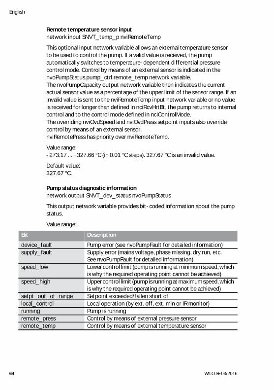
Remote temperature sensor inputnetwork input SNVT_temp_p nviRemoteTemp
This optional input network variable allows an external temperature sensor to be used to control the pump. If a valid value is received, the pump automatically switches to temperature-dependent differential pressure control mode. Control by means of an external sensor is indicated in the nvoPumpStatus.pump_ctrl.remote_temp network variable.The nvoPumpCapacity output network variable then indicates the current actual sensor value as a percentage of the upper limit of the sensor range. If an invalid value is sent to the nviRemoteTemp input network variable or no value is received for longer than defined in nciRcvHrtBt, the pump returns to internal control and to the control mode defined in nciControlMode.The overriding nviOvdSpeed and nviOvdPress setpoint inputs also override control by means of an external sensor.nviRemotePress has priority over nviRemoteTemp.
Value range:-273.17 ... +327.66 °C (in 0.01 °C steps). 327.67 °C is an invalid value.
Default value: 327.67 °C.
Pump status diagnostic informationnetwork output SNVT_dev_status nvoPumpStatus
This output network variable provides bit-coded information about the pump status.
Value range:
Bit Description
device_fault Pump error (see nvoPumpFault for detailed information)supply_fault Supply error (mains voltage, phase missing, dry run, etc.
See nvoPumpFault for detailed information)speed_low Lower control limit (pump is running at minimum speed, which
is why the required operating point cannot be achieved)speed_high Upper control limit (pump is running at maximum speed, which
is why the required operating point cannot be achieved)setpt_out_of_range Setpoint exceeded/fallen short oflocal_control Local operation (by ext. off, ext. min or IR monitor)running Pump is runningremote_press Control by means of external pressure sensorremote_temp Control by means of external temperature sensor
Installation and operating instructions Wilo-Control IF-module LON / IF-module Stratos LON 65
English
Transmission:This value is automatically transmitted whenever a change is made.Furthermore, this value is transmitted regularly if the nciSndHrtBt configuration input was described with a valid clock.
Transmission frequency:The minimum network variable transmission interval can be set by describing the nciMinOutTm configuration input with a valid clock.
Preset service type: acknowledged
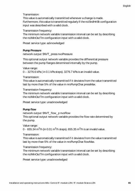
Pump Pressurenetwork output SNVT_press nvoPressure
This optional output network variable provides the differential pressure between the pump flanges determined internally by the pump.
Value range:0 – 3276.6 kPa ( in 0.1 kPa steps). 3276.7 kPa is an invalid value.
Transmission:This value is automatically transmitted if it deviates from the value transmitted last by more than 5% of the value in nroPumpChar.pressMax.
Transmission frequency:The minimum network variable transmission interval can be set by describing the nciMinOutTm configuration input with a valid clock.
Preset service type: unacknowledged
Pump flownetwork output SNVT_flow_p nvoFlowThis optional output network variable provides the flow rate determined by the pump.
Value range:0 - 655.34 m3/h (in 0.01 m3/h steps). 655.35 m3/h is an invalid value.
Transmission:This value is automatically transmitted if it deviates from the value transmitted last by more than 5% of the value in nroPumpChar.flowMax.
Transmission frequency:The minimum network variable transmission interval can be set by describing the nciMinOutTm configuration input with a valid clock.
Preset service type: unacknowledged
English
66 WILO SE 03/2016
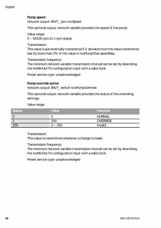
Pump speednetwork output SNVT_rpm nvoSpeed
This optional output network variable provides the speed of the pump.
Value range:0 – 65535 rpm (in 1 rpm steps).
Transmission:This value is automatically transmitted if it deviates from the value transmitted last by more than 2% of the value in nroPumpChar.speedMax.
Transmission frequency:The minimum network variable transmission interval can be set by describing the nciMinOutTm configuration input with a valid clock.
Preset service type: unacknowledged
Pump override active network output SNVT_switch nvoPumpOverride
This optional output network variable provides the status of the overriding settings.
Value range:
Transmission:This value is transmitted whenever a change is made.
Transmission frequency:The minimum network variable transmission interval can be set by describing the nciMinOutTm configuration input with a valid clock.
Preset service type: unacknowledged
Status Value Function
0 0 NORMAL1 200 OVERRIDE255 0 – 255 Invalid
Installation and operating instructions Wilo-Control IF-module LON / IF-module Stratos LON 67
English
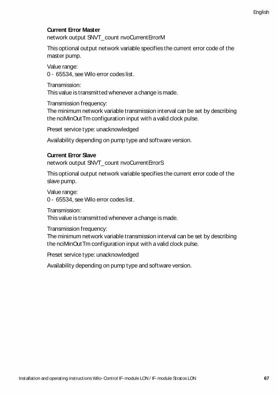
Current Error Masternetwork output SNVT_count nvoCurrentErrorM
This optional output network variable specifies the current error code of the master pump.
Value range:0 - 65534, see Wilo error codes list.
Transmission:This value is transmitted whenever a change is made.
Transmission frequency:The minimum network variable transmission interval can be set by describing the nciMinOutTm configuration input with a valid clock pulse.
Preset service type: unacknowledged
Availability depending on pump type and software version.
Current Error Slavenetwork output SNVT_count nvoCurrentErrorS
This optional output network variable specifies the current error code of the slave pump.
Value range:0 - 65534, see Wilo error codes list.
Transmission:This value is transmitted whenever a change is made.
Transmission frequency:The minimum network variable transmission interval can be set by describing the nciMinOutTm configuration input with a valid clock pulse.
Preset service type: unacknowledged
Availability depending on pump type and software version.
English
68 WILO SE 03/2016
Pump Status Masternetwork output SNVT_dev_status nvoPumpStatusM
This output network variable supplies bit coded information relating to the pump status of the master pump.
Value range:device_fault = pump fault
(see nvoPumpFault for more detailed information)supply_fault = supply fault
(mains voltage, phase missing, dry running, etc. See nvoPump-Fault for more detailed information)
running = pump running
Transmission:This value is automatically transmitted whenever a change is made.
Transmission frequency:The minimum network variable transmission interval can be set by describingthe nciMinOutTm configuration input with a valid clock pulse.
Preset service type: unacknowledged
Availability depending on pump type and software version.
Pump Status Slavenetwork output SNVT_dev_status nvoPumpStatusS
This output network variable supplies bit coded information relating to the pump status of the slave pump.
Value range:device_fault = pump fault
(see nvoPumpFault for more detailed information)supply_fault = supply fault
(mains voltage, phase missing, dry running, etc. See nvoPump-Fault for more detailed information)
running = pump running
Transmission:This value is transmitted whenever a change is made.
Transmission frequency:The minimum network variable transmission interval can be set by describing the nciMinOutTm configuration input with a valid clock pulse.
Preset service type: unacknowledged
Availability depending on pump type and software version.
Installation and operating instructions Wilo-Control IF-module LON / IF-module Stratos LON 69
English
Pump Typenetwork output SNVT_count nvoPumpType
This optional output network variable specifies the current pump type.
Value range:0 - 65534, see list of Wilo pump types
Transmission:This value is transmitted whenever a change is made.
Transmission frequency:The minimum network variable transmission interval can be set by describingthe nciMinOutTm configuration input with a valid clock pulse.
Preset service type: unacknowledged
Availability depending on pump type and software version.
Runtimenetwork output SNVT_time_hour nvoRuntime
This optional output network variable provides the operating hours of the pump, or with double pumps, the time during which at least one pump was running. The counter is reset to 0 h after 65535 h.
Value range:0 – 65535 h (in 10 h steps), (max. 2730 d or 7.48 a).
Transmission:This value is transmitted whenever a change is made.
Transmission frequency:The minimum network variable transmission interval can be set by describing the nciMinOutTm configuration input with a valid clock.
Preset service type: unacknowledged
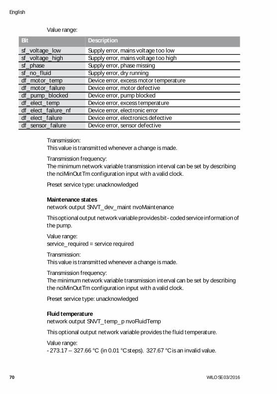
Fault states of the pumpnetwork output SNVT_dev_fault nvoPumpFault
This optional output network variable provides bit-coded error information of the pump. Errors can be device errors or supply errors.
English
70 WILO SE 03/2016
Value range:
Transmission:This value is transmitted whenever a change is made.
Transmission frequency:The minimum network variable transmission interval can be set by describing the nciMinOutTm configuration input with a valid clock.
Preset service type: unacknowledged
Maintenance statesnetwork output SNVT_dev_maint nvoMaintenance
This optional output network variable provides bit-coded service information of the pump.
Value range:service_required = service required
Transmission:This value is transmitted whenever a change is made.
Transmission frequency:The minimum network variable transmission interval can be set by describing the nciMinOutTm configuration input with a valid clock.
Preset service type: unacknowledged
Fluid temperaturenetwork output SNVT_temp_p nvoFluidTemp
This optional output network variable provides the fluid temperature.
Value range:-273.17 – 327.66 °C (in 0.01 °C steps). 327.67 °C is an invalid value.
Bit Description
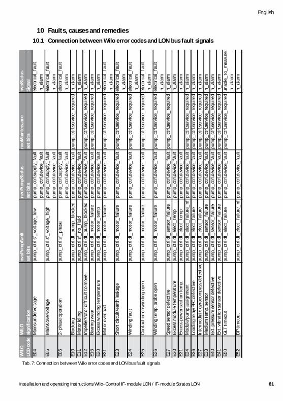
sf_voltage_low Supply error, mains voltage too lowsf_voltage_high Supply error, mains voltage too highsf_phase Supply error, phase missingsf_no_fluid Supply error, dry runningdf_motor_temp Device error, excess motor temperaturedf_motor_failure Device error, motor defectivedf_pump_blocked Device error, pump blockeddf_elect_temp Device error, excess temperaturedf_elect_failure_nf Device error, electronic errordf_elect_failure Device error, electronics defectivedf_sensor_failure Device error, sensor defective
Installation and operating instructions Wilo-Control IF-module LON / IF-module Stratos LON 71
English
Transmission:This value is automatically transmitted if it deviates from the value transmitted last by more than 5 °C.
Transmission frequency:The minimum network variable transmission interval can be set by describing the nciMinOutTm configuration input with a valid clock.
Preset service type: unacknowledged
Power consumption in wattsnetwork output SNVT_power nvoPower
This optional output network variable provides the power consumption of the pump or, in the event of double pumps, the total power output of the master and slave.
Value range:0 – 6553,5 W (in 0,1 W steps).
Transmission:This value is automatically transmitted if it deviates from the value transmitted last by more than 10% of the maximum power consumption of the pump.
Transmission frequency:The minimum network variable transmission interval can be set by describing the nciMinOutTm configuration input with a valid clock.
Preset service type: unacknowledged
Power consumption in Kilowattsnetwork output SNVT_power_kilo nvoPowerkilo
This optional output network variable provides the power consumption of the pump or, in the event of double pumps, the total power output of the master and slave.
Value range:0 – 6553.5 kW (in 0.1 kW steps).
Transmission:This value is automatically transmitted if it deviates from the value transmitted last by more than 10% of the maximum power consumption of the pump.
Transmission frequency:The minimum network variable transmission interval can be set by describing the nciMinOutTm configuration input with a valid clock.
Preset service type: unacknowledged
English
72 WILO SE 03/2016
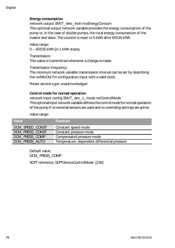
Energy consumptionnetwork output SNVT_elec_kwh nvoEnergyConsumThis optional output network variable provides the energy consumption of the pump or, in the case of double pumps, the total energy consumption of the master and slave. The counter is reset to 0 kWh after 65535 kWh.
Value range:0 – 65535 kWh (in 1 kWh steps).
Transmission:This value is transmitted whenever a change is made.
Transmission frequency:The minimum network variable transmission interval can be set by describing the nciMinOutTm configuration input with a valid clock.
Preset service type: unacknowledged
Control mode for normal operationnetwork input config SNVT_dev_c_mode nciControlModeThis optional input network variable defines the control mode for normal operation of the pump if no external sensors are used and no overriding settings are active.
Value range:
Default value:DCM_PRESS_COMP
SCPT reference: SCPTdeviceControlMode (238)
Value Function
DCM_SPEED_CONST Constant speed modeDCM_PRESS_CONST Constant pressure modeDCM_PRESS_COMP Compensated pressure modeDCM_PRESS_AUTO Temperature-dependent differential pressure
Installation and operating instructions Wilo-Control IF-module LON / IF-module Stratos LON 73
English
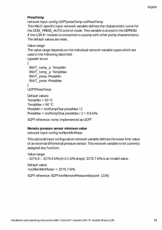
PressTempnetwork input config UCPTpressTemp nciPressTempThis WILO-specific input network variable defines the characteristic curve for the DCM_PRESS_AUTO control mode. This variable is stored in the EEPROM. If the LON IF-module is connected to a pump with other pump characteristics . The default values are reset.
Value range:The value range depends on the individual network variable types which are used in the following data field:typedef struct{ SNVT_temp_p TempMin SNVT_temp_p TempMax SNVT_press PressMin SNVT_press PressMax}UCPTPressTemp
Default values:TempMin = 50 °CTempMax = 90 °CPressMin = nroPumpChar.pressMax / 2PressMax = nroPumpChar.pressMax / 2 + 9.8 kPa
SCPT reference: none; implemented as UCPT
Remote pressure sensor minimum valuenetwork input config nciRemMinPress
This optional input configuration network variable defines the lower limit value of an external differential pressure sensor. This network variable is not currently assigned any function.
Value range:-3276.8 – 3276.6 kPa (in 0.1 kPa steps). 3276.7 kPa is an invalid value.
Default value:<nciRemMinPress> = 3276.7 kPa
SCPT reference: SCPTminRemotePressureSetpoint (239)
English
74 WILO SE 03/2016
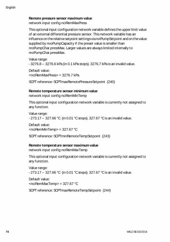
Remote pressure sensor maximum valuenetwork input config nciRemMaxPress
This optional input configuration network variable defines the upper limit value of an external differential pressure sensor. This network variable has an influence on the relative setpoint settings via nviPumpSetpoint and on the value supplied by nvoPumpCapacity if the preset value is smaller than nroPumpChar.pressMax. Larger values are always limited internally to nroPumpChar.pressMax.
Value range:-3276.8 – 3276.6 kPa (in 0.1 kPa steps). 3276.7 kPa is an invalid value.
Default value:<nciRemMaxPress> = 3276.7 kPa
SCPT reference: SCPTmaxRemotePressureSetpoint (240)
Remote temperature sensor minimum valuenetwork input config nciRemMinTemp
This optional input configuration network variable is currently not assigned to any function.
Value range:-273.17 – 327.66 °C (in 0.01 °C steps). 327.67 °C is an invalid value.
Default value:<nciRemMinTemp> = 327.67 °C
SCPT reference: SCPTminRemoteTempSetpoint (243)
Remote temperature sensor maximum valuenetwork input config nciRemMaxTemp
This optional input configuration network variable is currently not assigned to any function.
Value range:-273.17 – 327.66 °C (in 0.01 °C steps). 327.67 °C is an invalid value.
Default value:<nciRemMaxTemp> = 327.67 °C
SCPT reference: SCPTmaxRemoteTempSetpoint (244)
Installation and operating instructions Wilo-Control IF-module LON / IF-module Stratos LON 75
English
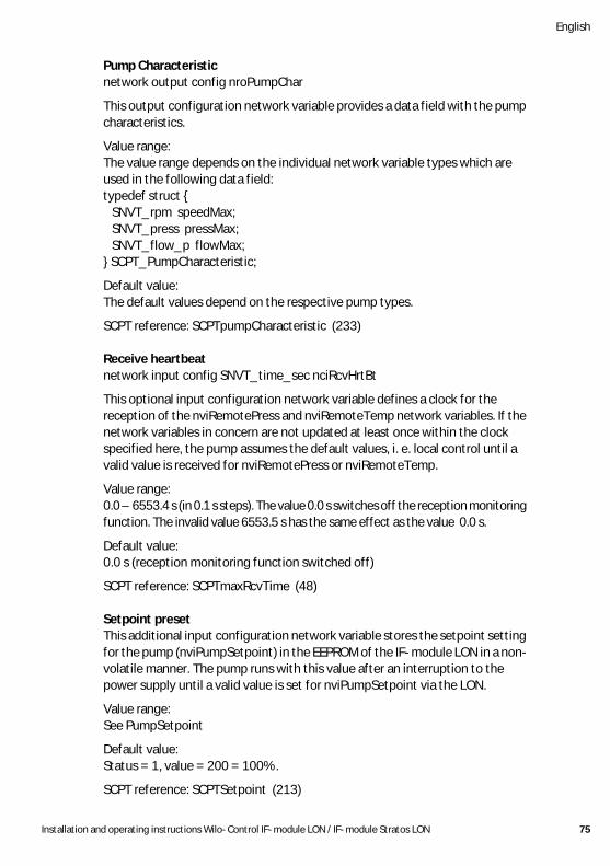
Pump Characteristicnetwork output config nroPumpChar
This output configuration network variable provides a data field with the pump characteristics.
Value range:The value range depends on the individual network variable types which are used in the following data field:typedef struct { SNVT_rpm speedMax; SNVT_press pressMax; SNVT_flow_p flowMax;} SCPT_PumpCharacteristic;
Default value:The default values depend on the respective pump types.
SCPT reference: SCPTpumpCharacteristic (233)
Receive heartbeatnetwork input config SNVT_time_sec nciRcvHrtBt
This optional input configuration network variable defines a clock for the reception of the nviRemotePress and nviRemoteTemp network variables. If the network variables in concern are not updated at least once within the clock specified here, the pump assumes the default values, i. e. local control until a valid value is received for nviRemotePress or nviRemoteTemp.
Value range:0.0 – 6553.4 s (in 0.1 s steps). The value 0.0 s switches off the reception monitoring function. The invalid value 6553.5 s has the same effect as the value 0.0 s.
Default value:0.0 s (reception monitoring function switched off)
SCPT reference: SCPTmaxRcvTime (48)
Setpoint presetThis additional input configuration network variable stores the setpoint setting for the pump (nviPumpSetpoint) in the EEPROM of the IF-module LON in a non-volatile manner. The pump runs with this value after an interruption to the power supply until a valid value is set for nviPumpSetpoint via the LON.
Value range:See PumpSetpoint
Default value:Status = 1, value = 200 = 100%.
SCPT reference: SCPTSetpoint (213)
English
76 WILO SE 03/2016
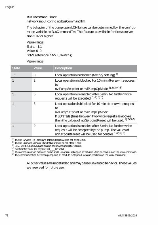
Bus Command Timernetwork input config nciBusCommandTm
The behavior of the pump upon LON failure can be determined by the configu-ration variable nciBusCommandTm. This feature is available for firmware ver-sion 2.02 or higher.
Value range:State: -1,1Value: 0-9SNVT reference: SNVT_switch ()
Value range:
All other values are undefinded and may cause unwanted behavior. Those values are reserved for future use.
State Value Description
-1 0 Local operation is blocked (factory setting) 4)
1 2 Local operation is blocked for 10 min after a write access to nvIPumpSetpoint or nviPumpOpMode 1) 2) 3) 4) 5)
1 5 Local operation is enabled after 5 min. No further write requests will be executed. 1) 2) 3) 6)
1 6 Local operation is blocked for 10 min after a write request to nviPumpSetpoint or nviPumpOpMode. If LON fails (time between two write reqests as above), then the values of nciSetpointPreset will be used. 1) 2) 3) 5)
1 9 Local operation is enabled after 5 min. No further write requests will be accepted by the pump. The values of nciSetpointPreset will be used for control. 1) 2) 3) 6)
1) The bit unable_to_measure (NodeStatus) will be set after 5 min.2) The bit manual_control (NodeStatus) will be set after 5 min.3) E050 will be displayed and can be acknowledged after 10 min.4) nviPumpSetpoint (or any nviOvd___) is valid.5) The communication between pump and IF-module is stopped after 5 min. Also no reaction on the wink command.6) The communication between pump and IF-module is stopped. Also no reaction on the wink command.
Send heartbeatnetwork input config SNVT_time_sec nciSndHrtBt
This input configuration network variable defines a clock at which certain output network variables are automatically sent (nvoPumpCapacity, nvoEffOpMode, nvoControlMode and nvoPumpStatus). A different network variable is sent with each clock.
Value range:0.0 – 6553.4 s (in 0.1 s steps). The value 0.0 s switches automatic sending off. The invalid value 6553.5 s has the same effect as the value 0.0 s.
Default value: 0.0 s (automatic sending switched off)
SCPT reference: SCPTmaxSendTime (49)
Minimum send timenetwork input config SNVT_time_sec nciMinOutTm
This optional input configuration network variable defines a minimum clock for the automatic transmission of network variables. The network variables are normally transmitted automatically if they have changed or if they have been changed at least by a certain amount. This network variable now has the effect that two transmission procedures are performed only at the specified interval. This is used, for example, to reduce the system load. The individual network variables are sent cyclically.
Value range:0.0 – 6553.4 s (in 0.1 s steps). The value 0.0 s switches off the minimum clock. The invalid value 6553.5 s has the same effect as the value 0.0 s.
Default value: 0.0 s
SCPT reference: SCPTminSendTime (52)
Object major version
network output config unsigned short nciObjMajVerThis output configuration network variable provides the high byte for the software version.
SCPT reference: SCPTobjMajVer (167)

Object minor versionnetwork output config unsigned short nciObjMinVer
This output configuration network variable provides the low byte for the software version.
SCPT reference: SCPTobjMinVer (168)
7 Installation and electrical connectionThe installation and electrical connections should be performed only by skilled staff in compliance with local regulations!WARNING! Danger of injury!The existing accident prevention regulations should be observed.WARNING! Danger from electric shock!Any hazards from electrical current should be ruled out.Any local or general directives [e.g. IEC, VDE etc.] and directives of the local power supply companies should be observed.
7.1 Installation and electrical connection of the IF-moduleNOTE: The IF-module LON is equipped with a Neuron ID double sticker. One sticker remains on the IF-module, the other sticker can, for example, be stuck on the system plan in the position of the corresponding pump. The Neuron ID from the system plan can be read in with a barcode scanner or entered manually during binding.CAUTION! Risk of damage to the IF-module!The IF-module LON may only be conneceted or disconneceted if the pump is electrically isolated.
• Electrically isolate the pump.• Remove the terminal box cover after undoing the screws.• Connect the IF-module to the circuit board interface:
• Stratos/-D/-Z/-ZD .............. Fig. 3a• IP-E/DP-E ............................. Fig. 3b• Helix VE (1,1…4,0 kW) ......... Fig. 3b• MVIE (1,1…4,0 kW) .............. Fig. 3b• MHIE ...................................... Fig. 3b• MVISE .................................... Fig. 3b• IL-E/DL-E .............................. Fig. 3c• Helix VE (5,5…7,5 kW) ......... Fig. 3c• MVIE (5,5…7,5 kW) .............. Fig. 3c• All other pumps .... see pump operating manual.
Installation and operating instructions Wilo-Control IF-module LON / IF-module Stratos LON 79
English
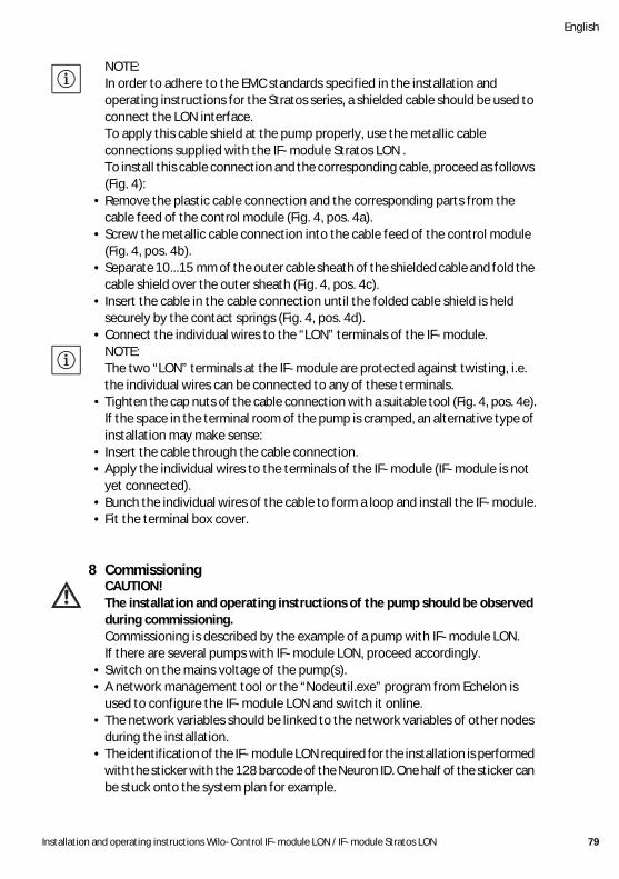
NOTE: In order to adhere to the EMC standards specified in the installation and operating instructions for the Stratos series, a shielded cable should be used to connect the LON interface.To apply this cable shield at the pump properly, use the metallic cable connections supplied with the IF-module Stratos LON .To install this cable connection and the corresponding cable, proceed as follows (Fig. 4):
• Remove the plastic cable connection and the corresponding parts from the cable feed of the control module (Fig. 4, pos. 4a).
• Screw the metallic cable connection into the cable feed of the control module (Fig. 4, pos. 4b).
• Separate 10...15 mm of the outer cable sheath of the shielded cable and fold the cable shield over the outer sheath (Fig. 4, pos. 4c).
• Insert the cable in the cable connection until the folded cable shield is held securely by the contact springs (Fig. 4, pos. 4d).
• Connect the individual wires to the “LON” terminals of the IF-module.NOTE: The two “LON” terminals at the IF-module are protected against twisting, i.e. the individual wires can be connected to any of these terminals.
• Tighten the cap nuts of the cable connection with a suitable tool (Fig. 4, pos. 4e).If the space in the terminal room of the pump is cramped, an alternative type of installation may make sense:
• Insert the cable through the cable connection.• Apply the individual wires to the terminals of the IF-module (IF-module is not
yet connected).• Bunch the individual wires of the cable to form a loop and install the IF-module.• Fit the terminal box cover.
8 Commissioning CAUTION!The installation and operating instructions of the pump should be observed during commissioning.Commissioning is described by the example of a pump with IF-module LON. If there are several pumps with IF-module LON, proceed accordingly.
• Switch on the mains voltage of the pump(s).• A network management tool or the “Nodeutil.exe” program from Echelon is
used to configure the IF-module LON and switch it online.• The network variables should be linked to the network variables of other nodes
during the installation.• The identification of the IF-module LON required for the installation is performed
with the sticker with the 128 barcode of the Neuron ID. One half of the sticker can be stuck onto the system plan for example.
English
80 WILO SE 03/2016
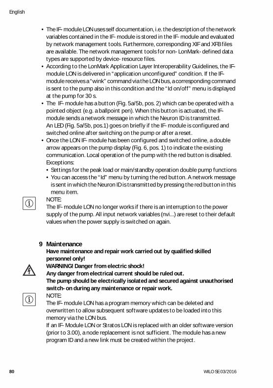
• The IF-module LON uses self documentation, i.e. the description of the network variables contained in the IF-module is stored in the IF-module and evaluated by network management tools. Furthermore, corresponding XIF and XFB files are available. The network management tools for non-LonMark-defined data types are supported by device-resource files.
• According to the LonMark Application Layer Interoperability Guidelines, the IF-module LON is delivered in “application unconfigured” condition. If the IF-module receives a “wink” command via the LON bus, a corresponding command is sent to the pump also in this condition and the “Id on/off” menu is displayed at the pump for 30 s.
• The IF-module has a button (Fig. 5a/5b, pos. 2) which can be operated with a pointed object (e.g. a ballpoint pen). When this button is actuated, the IF-module sends a network message in which the Neuron ID is transmitted.An LED (Fig. 5a/5b, pos.1) goes on briefly if the IF-module is configured and switched online after switching on the pump or after a reset.
• Once the LON IF-module has been configured and switched online, a double arrow appears on the pump display (Fig. 6, pos. 1) to indicate the existing communication. Local operation of the pump with the red button is disabled.Exceptions:• Settings for the peak load or main/standby operation double pump functions• You can access the “Id” menu by turning the red button. A network message
is sent in which the Neuron ID is transmitted by pressing the red button in this menu item.
NOTE: The IF-module LON no longer works if there is an interruption to the power supply of the pump. All input network variables (nvi...) are reset to their default values when the power supply is switched on again.
9 MaintenanceHave maintenance and repair work carried out by qualified skilled personnel only!WARNING! Danger from electric shock!Any danger from electrical current should be ruled out.The pump should be electrically isolated and secured against unauthorised switch-on during any maintenance or repair work.NOTE: The IF-module LON has a program memory which can be deleted and overwritten to allow subsequent software updates to be loaded into this memory via the LON bus.If an IF-Module LON or Stratos LON is replaced with an older software version (prior to 3.00), a node replacement is not sufficient. The module has a new program ID and a new link must be created within the project.
Installation and operating instructions Wilo-Control IF-module LON / IF-module Stratos LON 81
English
10 Faults, causes and remedies10.1 Connection between Wilo error codes and LON bus fault signals
nvoS
tatu
sSi
gnal
elec
tric
al_
faul
tin
_al
arm
elec
tric
al_
faul
tin
_al
arm
elec
tric
al_
faul
tin
_al
arm
in_
alar
min
_al
arm
in_
alar
min
_al
arm
in_
alar
mel
ectr
ical
_fa
ult
in_
alar
mel
ectr
ical
_fa
ult
in_
alar
mel
ectr
ical
_fa
ult
in_
alar
mel
ectr
ical
_fa
ult
in_
alar
mel
ectr
ical
_fa
ult
in_
alar
min
_al
arm
in_
alar
min
_al
arm
in_
alar
min
_al
arm
in_
alar
min
_al
arm
in_
alar
min
_al
arm
unab
le_
to_
mea
sure
in_
alar
min
_al
arm
nvoM
aint
enan
cese
t bi
ts
pum
p_ct
rl.se
rvic
e_re
quire
d
pum
p_ct
rl.se
rvic
e_re
quire
dpu
mp_
ctrl.
serv
ice_
requ
ired
pum
p_ct
rl.se
rvic
e_re
quire
d
pum
p_ct
rl.se
rvic
e_re
quire
d
pum
p_ct
rl.se
rvic
e_re
quire
d
pum
p_ct
rl.se
rvic
e_re
quire
d
pum
p_ct
rl.se
rvic
e_re
quire
d
pum
p_ct
rl.se
rvic
e_re
quire
d
pum
p_ct
rl.se
rvic
e_re
quire
dpu
mp_
ctrl.
serv
ice_
requ
ired
pum
p_ct
rl.se
rvic
e_re
quire
dpu
mp_
ctrl.
serv
ice_
requ
ired
pum
p_ct
rl.se
rvic
e_re
quire
dpu
mp_
ctrl.
serv
ice_
requ
ired
pum
p_ct
rl.se
rvic
e_re
quire
d
nvoP
umpS
tatu
sse
t bi
tspu
mp_
ctrl.
supp
ly_
faul
tpu
mp_
ctrl.
devi
ce_
faul
tpu
mp_
ctrl.
supp
ly_
faul
tpu
mp_
ctrl.
devi
ce_
faul
tpu
mp_
ctrl.
supp
ly_
faul
tpu
mp_
ctrl.
devi
ce_
faul
tpu
mp_
ctrl.
devi
ce_
faul
tpu
mp_
ctrl.
devi
ce_
faul
tpu
mp_
ctrl.
devi
ce_
faul
tpu
mp_
ctrl.
devi
ce_
faul
tpu
mp_
ctrl.
devi
ce_
faul
tpu
mp_
ctrl.
devi
ce_
faul
t
pum
p_ct
rl.de
vice
_fa
ult
pum
p_ct
rl.de
vice
_fa
ult
pum
p_ct
rl.de
vice
_fa
ult
pum
p_ct
rl.de
vice
_fa
ult
pum
p_ct
rl.de
vice
_fa
ult
pum
p_ct
rl.de
vice
_fa
ult
pum
p_ct
rl.de
vice
_fa
ult
pum
p_ct
rl.de
vice
_fa
ult
pum
p_ct
rl.de
vice
_fa
ult
pum
p_ct
rl.de
vice
_fa
ult
pum
p_ct
rl.de
vice
_fa
ult
pum
p_ct
rl.de
vice
_fa
ult
pum
p_ct
rl.de
vice
_fa
ult
pum
p_ct
rl.de
vice
_fa
ult
pum
p_ct
rl.de
vice
_fa
ult
nvoP
umpF
ault
set
bits
pum
p_ct
rl.sf
_vo
ltage
_lo
w
pum
p_ct
rl.sf
_vo
ltage
_hi
gh
pum
p_ct
rl.sf
_ph
ase
pum
p_ct
rl.df
_pu
mp_
bloc
ked
pum
p_ct
rl.sf
_no
_flu
idpu
mp_
ctrl.
df_
pum
p_bl
ocke
dpu
mp_
ctrl.
df_
mot
or_
failu
repu
mp_
ctrl.
df_
mot
or_
tem
ppu
mp_
ctrl.
df_
mot
or_
failu
re
pum
p_ct
rl.df
_m
otor
_fa
ilure
pum
p_ct
rl.df
_m
otor
_fa
ilure
pum
p_ct
rl.df
_m
otor
_fa
ilure
pum
p_ct
rl.df
_m
otor
_fa
ilure
pum
p_ct
rl.df
_se
nsor
_fa
ilure
pum
p_ct
rl.df
_el
ect_
tem
ppu
mp_
ctrl.
df_
elec
t_te
mp
pum
p_ct
rl.df
_el
ect_
failu
re_
nfpu
mp_
ctrl.
df_
elec
t_fa
ilure
pum
p_ct
rl.df
_el
ect_
failu
repu
mp_
ctrl.
df_
sens
or_
failu
repu
mp_
ctrl.
df_
sens
or_
failu
repu
mp_
ctrl.
df_
sens
or_
failu
repu
mp_
ctrl.
df_
elec
t_fa
ilure
pum
p_ct
rl.df
_el
ect_
failu
re_
nf
WIL
Osi
gnif
icat
ion
Mai
ns u
nder
volta
ge
Mai
ns o
verv
olta
ge
2-ph
ase
oper
atio
n
Bloc
king
Mot
or id
ling
Impe
ller/
roto
r diff
icul
t to
mov
eBe
arin
g w
ear
Exce
ss w
indi
ng te
mpe
ratu
reM
otor
ove
rload
Shor
t circ
uit/
eart
h le
akag
e
Win
ding
faul
t
Cont
act e
rror
/win
ding
ope
n
Win
ding
tem
p. p
robe
ope
n
Spee
d se
nsor
def
ectiv
eEx
cess
mod
ule
tem
pera
ture
Exce
ss p
ower
sec
tion
tem
p.M
odul
e/pu
mp
assi
gnm
ent
Load
ing
rela
y/PF
C de
fect
ive
Inte
rmed
iate
gyr
ocom
pass
def
ectiv
eM
ediu
m te
mp.
sen
sor
Ext.
pres
sure
sen
sor d
efec
tive
Ext.
vibr
atio
n se
nsor
def
ectiv
eG
LT ti
meo
ut
DP
timeo
ut
WIL
OLC
D c
ode
E04
E05
E06
E10
E11
E12
E16
E20
E21
E23
E24
E25
E26
E27
E30
E31
E34
E36
E37
E38
E40
E41
E50
E52
Tab. 7: Connection between Wilo error codes and LON bus fault signals
English
82 WILO SE 03/2016
NOTE: The installation and operating instructions for the respective pumps should be observed during error diagnostics.If the pump / IF-module malfunction is unable to be rectified, please contact a specialist or the nearest Wilo customer service or representative.
11 DisposalProper disposal and recycling of this product prevents damage to the environment and risks to personal health.1. Use public or private disposal organisations when disposing of all or part of the product.2. For more information on proper disposal, please contact your local council or waste disposal office or the supplier from whom you obtained the product.
NOTE: The product or any of its parts must not be disposed of with household waste! For further information on recycling, go to: www.wilo-recycling.com
Subject to change without prior notice!

WILO SENortkirchenstraße 100D-44263 DortmundGermanyT +49(0)231 4102-0F +49(0)231 [email protected] for You