Embed Size (px)
Citation preview

E.& O.E. – Subject to change without prior notice
Glandless PumpsStandard 3-Speed Pumps (max. 2800 r.p.m.)
Wilo-TOP-S 73
Wilo-TOP-S
[m3/h][l/s]
16
14
12
10
8
6
4
2
0
0 2 4 6 8 10 12 14 16 180 10 20 30 40 50 60
65/15
80/10100/10
25/730/7
50/4
65/10 80/7
50/10 65/1340/1030/10
40/7
40/4
50/7 65/7
GesamtkennfeldWilo-TOP-S
H [
m]
Q
50/15
Wilo-TOP-SSingle head pumpScrew-/flange-ended circulating pumps
Identification Codee.g.: Wilo-TOP-S 40/10TOP-S Screw-/flange-ended pump40/ DN connection size10 Rated shut-off head
Fields of ApplicationCentral heating and air conditioninginstallations, closed chilled water andindustrial circulating systems
Technical DataSuitable Fluids
Heating water to VDI 2035
Water/glycol mixtures, max. mixing ratio 1:1.
Hydraulic corrections required for mixing ratioabove 20%
Performance
Speed range: 1600-2850 rpm
-speed manual control
Max.working pressure: 6/10 bar(Special design: PN 16 at Tmax. = 130 °C)
Temperature range: –10°C bis +130°CShort term: up to +140°C
Max. permissible continuous temperature withDisplay Module
T= +20 °C to +110 °C
Ambient Temperaturepermissible up to 40ºC
Electrical wiring
Mains power 1 ~ 230-240 V, 50 Hz3 ~ 400-415 V, 50 Hz
Non standard motor on request
Optional for 3 ~ 230-240 V, 50 Hzwith ‘Wilo 3~ 230 V Adapter Plug’ 3 ~ 230 V“,(see section ‘Service/Accessories)
Motor
Degree of protection IP 43
Insulation class F
Interference emission: EN 50081-1
Interference resistance: EN 50082-2
Construction Materials
Pump body cast iron
Impeller GF-PP
Shaft stainless steel
Bearings metal impregnated carbon
Mounting positions and combination flange
see Planning Guide
Scope of SupplyPump, thermal insulation incl. packing,O.&M. manual, 2 union washers forsrewed-end pumps
Accessoriesfor Pumps 3~ 400V
– Display-Module 400V– 3~ 230 V Adapter Plug for
3~ 230-240V/50Hz– Union connector fittings
for Pumps 1~ 230V– Wilo contactor box SK 602/SK 622– Union connector fittings
Pump EquipmentPump Equipment– Single head pump with screwed,
flanged or combination PN 6/10 flangedends, (1" to DN 100)
– Thermal insulation as standard– Pumps 3~ 400V
– Non overloading motors or integratedoverload trip relay
– Run light combined with rotation con-trol
– Voltfree fault signal as standard oroptionally with Wilo-Display-Module
– Pumps 1~ 230V– non-overloading motors or overload
protection by thermal contacts (WSK)in conjunction with Wilo-SK 602/622contactor box
See also Wilo-TOP-Control and AS-/CR-control gear in catalogue section”Switchgear and Control Systems”
Connection size DN 1" 11/4" 40 50 65 80 100Screwed-end connections � � – – – – – – –
Flanges and 1/8" gauge tappingsFlanges to fit mating flanges PN 06 – – � � – � – � �
PN 16 – – � � – � – � �to DIN/DIN EN respectively
Combination flanges PN 6/10 to fit mating flanges PN 6 and PN 16 to DIN /DIN EN – – – – � – � – –
Max. working pressure 06 bar – – � � � � � � �10 bar � � � � � � � � �16 bar – – � – � � � � � � � �
Minimum inlet pressure (m) at the pumpsuction inlet to avoid cavitation noise at +40°C ambient and water temperatures ϑmax.:
50°C 0.5 395°C 5 10110°C 11 16130°C 24 29
Wilo-TOP-SPump data
● Standard design � Special design (to order at additional costs)
S25
/7
S30
/7S
30/
10S
40/
4S
40/7
S 4
0/10
S 5
0/4
S50
/7S
50/
10
S50
/15
S65
/7S
65/1
0S
65/1
3
S65
/15
S80
/7S
80/1
0
S10
0/10
Duty Chart
E.& O.E. – Subject to change without prior notice
Adaptability: Display-Module/Pump Display-Module Pump type (3 ~ 400 V)Type 22 TOP-S 25/7
TOP-S 30/7TOP-S 40/4
Type 32 TOP-S 30/10TOP-S 40/7TOP-S 50/4
Type 42 TOP-S 40/10TOP-S 50/7 toTOP-S 100/10
Glandless PumpsStandard 3-Speed Pumps (max. 2800 r.p.m.)
74 Wilo-TOP-S
Modular Plug-In Adapter Technology - Wilo-TOP-S Pumps
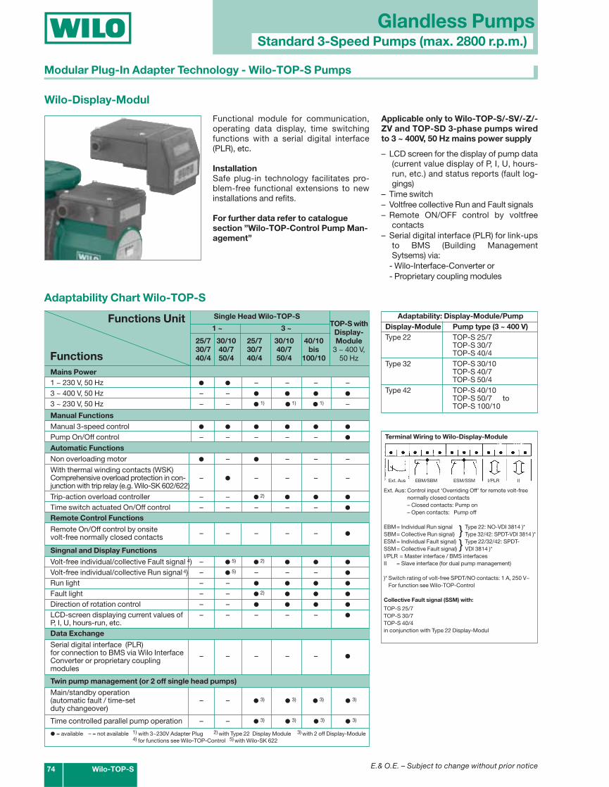
Wilo-Display-Modul
Functional module for communication,operating data display, time switchingfunctions with a serial digital interface(PLR), etc.
InstallationSafe plug-in technology facilitates pro-blem-free functional extensions to newinstallations and refits.
For further data refer to catalogue section ”Wilo-TOP-Control Pump Man-agement”
Applicable only to Wilo-TOP-S/-SV/-Z/-ZV and TOP-SD 3-phase pumps wiredto 3 ~ 400V, 50 Hz mains power supply
– LCD screen for the display of pump data(current value display of P, I, U, hours-run, etc.) and status reports (fault log-gings)
– Time switch– Voltfree collective Run and Fault signals– Remote ON/OFF control by voltfree
contacts– Serial digital interface (PLR) for link-ups
to BMS (Building ManagementSytsems) via:
- Wilo-Interface-Converter or- Proprietary coupling modules
Terminal Wiring to Wilo-Display-Module
Ext. Aus: Control input ‘Overriding Off’ for remote volt-free normally closed contacts– Closed contacts: Pump on– Open contacts: Pump off
EBM= Individual Run signal Type 22: NO-VDI 3814 )*SBM= Collective Run signal) Type 32/42: SPDT-VDI 3814 )*ESM= Individual Fault signal) Type 22/32/42: SPDT-SSM= Collective Fault signal) VDI 3814 )*I/PLR = Master interface / BMS interfacesII = Slave interface (for dual pump management)
)* Switch rating of volt-free SPDT/NO contacts: 1 A, 250 V~For function see Wilo-TOP-Control
Collective Fault signal (SSM) with:
TOP-S 25/7TOP-S 30/7TOP-S 40/4in conjunction with Type 22 Display-Modul
Ext. Aus EBM/SBM ESM/SSM I/PLR II
}}
Functions Unit
Functions
Single Head Wilo-TOP-S
1 ~ 3 ~
25/7 30/10 25/7 30/10 40/1030/7 40/7 30/7 40/7 bis40/4 50/4 40/4 50/4 100/10
TOP-S withDisplay-Module
3 ~ 400 V,50 Hz
Adaptability Chart Wilo-TOP-S
Mains Power1 ~ 230 V, 50 Hz � � – – – –3 ~ 400 V, 50 Hz – – � � � �
3 ~ 230 V, 50 Hz – – � 1) � 1) � 1) –
Manual FunctionsManual 3-speed control � � � � � �
Pump On/Off control – – – – – �
Automatic FunctionsNon overloading motor � – � – – –
With thermal winding contacts (WSK)Comprehensive overload protection in con- – � – – – –junction with trip relay (e.g. Wilo-SK 602/622)
Trip-action overload controller – – � 2) � � �
Time switch actuated On/Off control – – – – – �
Remote Control Functions
Remote On/Off control by onsite – – – – – �volt-free normally closed contacts
Singnal and Display Functions
Volt-free individual/collective Fault signal 4) – � 5) � 2) � � �
Volt-free individual/collective Run signal 4) – � 5) – – – �
Run light – – � � � �
Fault light – – � 2) � � �
Direction of rotation control – – � � � �
LCD-screen displaying current values of – – – – – �P, I, U, hours-run, etc.Data Exchange
Serial digital interface (PLR)
– – – – – �for connection to BMS via Wilo Interface Converter or proprietary coupling modules
Twin pump management (or 2 off single head pumps)
Main/standby operation (automatic fault / time-set – – � 3) � 3) � 3) � 3)
duty changeover)
Time controlled parallel pump operation – – � 3) � 3) � 3) � 3)
� = available – = not available 1) with 3~230V Adapter Plug 2) with Type 22 Display Module 3) with 2 off Display-Module4) for functions see Wilo-TOP-Control 5) with Wilo-SK 622
E.& O.E. – Subject to change without prior notice
G
b
b
Rp
b
la
a
l
Pg
Verschraubungen(Zubehör)
1
2
3
12
1
O
b2
Glandless PumpsStandard 3-Speed Pumps (max. 2800 r.p.m.)
Wilo-TOP-S 75
6 10/16 PN 10
1" 11/2" 180 34 56 164 66 80 95 – – 5.0
11/4" 2" 180 34 64 171 66 88 95 – – 5.0
TOP-S 25/7
TOP-S 30/7
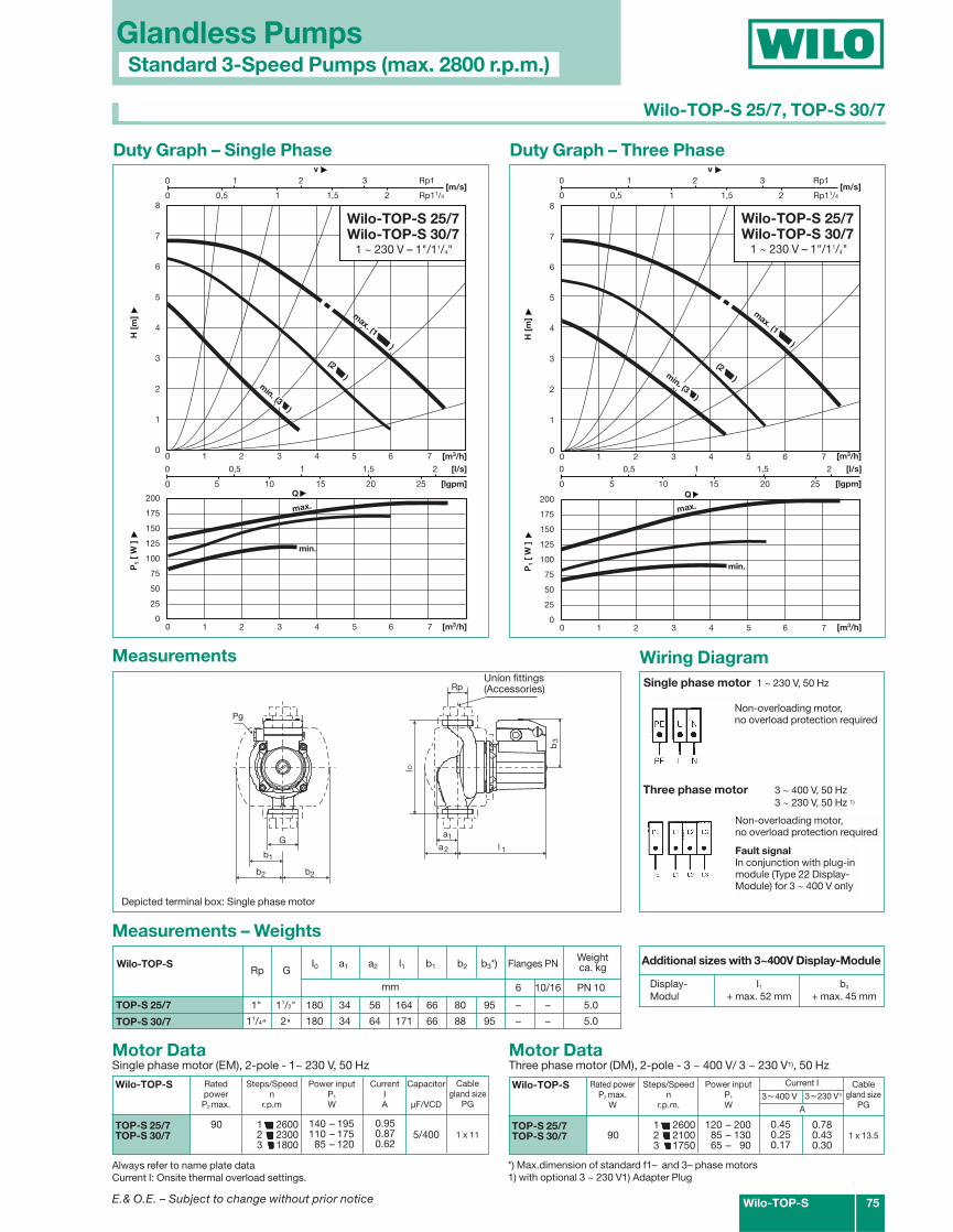
Wilo-TOP-S 25/7, TOP-S 30/7
Measurements – Weights
Motor DataThree phase motor (DM), 2-pole - 3 ~ 400 V/ 3 ~ 230 V1), 50 Hz
0 1 2 3 Rp1
0 0,5 1 1,5 2
0 5 10 15 20 25
0 1 2 3 4 5 6 7
0 1 2 3 4 5 6 7
v
[m3/h]
P1
[ W
]H
[m
]
Q
[m3/h]
[lgpm]
200
175
150
125
100
75
50
25
0
8
7
6
5
4
3
2
1
0
[l/s]
min.
max.
Wilo-TOP-S 25/7Wilo-TOP-S 30/71~230 V - Rp1/Rp11/4
max. (1 )
(2 )
0 0,5 1 1,5 2 Rp11/4
[m/s]
min. (3 )
Duty Graph – Single Phase Duty Graph – Three Phase
Wilo-TOP-S
TOP-S 25/7TOP-S 30/7
Rated powerP2 max.
W
90
Current I
0.450.250.17
3~230 V1)
Power inputP1
W
Steps/Speedn
r.p.m.
1 26002 21003 1750
200
175
150
125
100
75
50
25
0
0 0,5 1 1,5 2
0 5 10 15 20 25
0 1 2 3 4 5 6 7
0 1 2 3 4 5 6 7 [m3/h]
P1
[ W
]H
[m
]
Q
[m3/h]
[lgpm]
8
7
6
5
4
3
2
1
0
[l/s]
min.
max.
min. (3 )
(2 )
max. (1 )
Wilo-TOP-S 25/7Wilo-TOP-S 30/73~400 V - Rp1/Rp11/4
0 1 2 3 Rp1v
0 0,5 1 1,5 2 Rp11/4
[m/s]
Flanges PNWeightca. kgI0 a1 a2 l1 b1 b2 b3*)
Motor DataSingle phase motor (EM), 2-pole - 1~ 230 V, 50 Hz
Wilo-TOP-S
TOP-S 25/7TOP-S 30/7
RatedpowerP2 max.
90
CurrentIA
Capacitor
µF/VCD
5/400
Power inputP1
W
Steps/Speedn
r.p.m
1 26002 23003 1800
A
0.780.430.30
3~400 V
120 – 20085 – 13065 – 90
140 – 195110 – 17585 – 120
0.950.870.62
Cablegland size
PG
1 x 13.5
Cablegland size
PG
1 x 11
Rp GWilo-TOP-S
mm
*) Max.dimension of standard f1– and 3– phase motors1) with optional 3 ~ 230 V1) Adapter Plug
Always refer to name plate dataCurrent I: Onsite thermal overload settings.
Additional sizes with 3~400V Display-Module
Display- I1 b3
Modul + max. 52 mm + max. 45 mm
Wiring DiagramMeasurements
Depicted terminal box: Single phase motor
Union fittings(Accessories)
1 ~ 230 V – 1"/11/4" 1 ~ 230 V – 1"/11/4"
Single phase motor 1 ~ 230 V, 50 Hz
Three phase motor 3 ~ 400 V, 50 Hz3 ~ 230 V, 50 Hz 1)
Fault signalIn conjunction with plug-inmodule (Type 22 Display-Module) for 3 ~ 400 V only
Non-overloading motor,no overload protection required
Non-overloading motor,no overload protection required
E.& O.E. – Subject to change without prior notice
6 10/16 PN 10
11/4" 2" 180 40 68 181 73 93 105 – – 7.0
Glandless PumpsStandard 3-Speed Pumps (max. 2800 r.p.m.)
76 Wilo-TOP-S
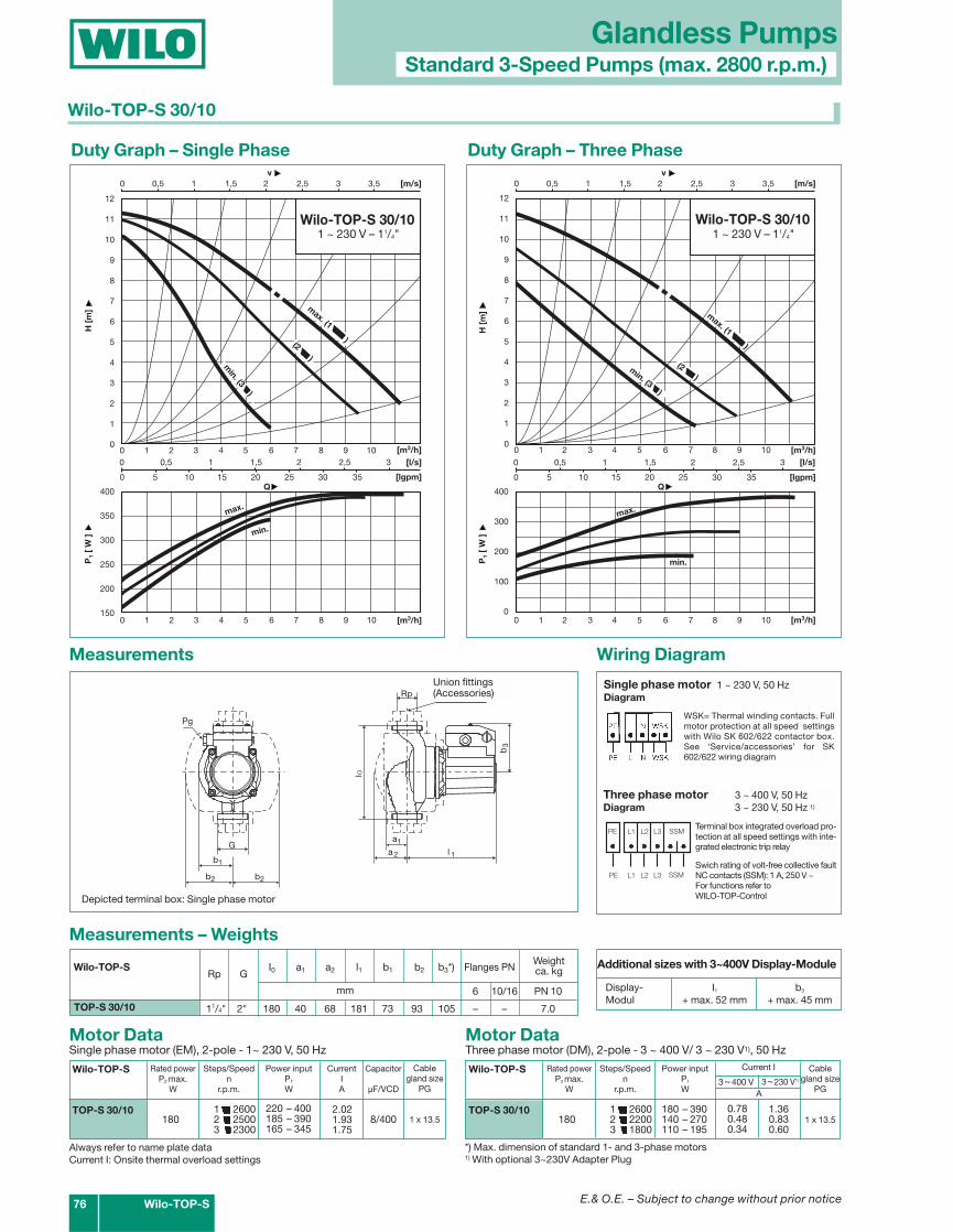
Wilo-TOP-S 30/10
TOP-S 30/10
Measurements – Weights
Motor DataThree phase motor (DM), 2-pole - 3 ~ 400 V/ 3 ~ 230 V1), 50 Hz
0 0,5 1 1,5 2 2,5 3
0 5 10 15 20 25 30 35
0 1 2 3 4 5 6 7 8 9 10
0 1 2 3 4 5 6 7 8 9 10 [m3/h]
P1
[ W
]H
[m
]
Q
[m3/h]
[lgpm]
400
350
300
250
200
150
12
11
10
9
8
7
6
5
4
3
2
1
0
[l/s]
min.
max.
Wilo-TOP-S 30/101 ~ 230 V - Rp11/4
min. (3 )
max. (1 )(2 )
0 0,5 1 1,5 2 2,5 3 3,5 v
[m/s]
Duty Graph – Single Phase Duty Graph – Three Phase
Wilo-TOP-S
TOP-S 30/10
Rated powerP2 max.
W
180
Current I
0.780.480.34
3~230 V1)
Power inputP1
W
Steps/Speedn
r.p.m.
1 26002 22003 1800
0 1 2 3 4 5 6 7 8 9 10
H [
m]
[m3/h]0 0,5 1 1,5 2 2,5 3
0 5 10 15 20 25 30 35 [lgpm]
[l/s]
400
300
200
100
00 1 2 3 4 5 6 7 8 9 10 [m3/h]
P1
[ W
]Q
min.
max.
0 0,5 1 1,5 2 2,5 3 3,5 v
[m/s]
Wilo-TOP-S 30/103 ~ 400 V - Rp11/4
max. (1 )
(2 )
12
11
10
9
8
7
6
5
4
3
2
1
0
min. (3 )
Flanges PNWeightca. kgG I0 a1 a2 l1 b1 b2 b3*)
Motor DataSingle phase motor (EM), 2-pole - 1~ 230 V, 50 Hz
Wilo-TOP-S
TOP-S 30/10
Rated powerP2 max.
W
180
CurrentIA
Capacitor
µF/VCD
8/400
Power inputP1
W
Steps/Speedn
r.p.m.
1 26002 25003 2300
A
1.360.830.60
3~400 V
180 – 390140 – 270110 – 195
220 – 400185 – 390165 – 345
2.021.931.75
Cablegland size
PG
1 x 13.5
Cablegland size
PG
1 x 13.5
Rp GWilo-TOP-S
mm
Wiring Diagram
L1 L2 L3 SSM
L1 L2 L3 SSM
PE
PE
*) Max. dimension of standard 1- and 3-phase motors1) With optional 3~230V Adapter Plug
Always refer to name plate dataCurrent I: Onsite thermal overload settings
Additional sizes with 3~400V Display-Module
Display- I1 b3
Modul + max. 52 mm + max. 45 mm
G
b
b
Rp
b
la
a
l
Pg
Verschraubungen(Zubehör)
1
2
3
12
1
O
b2
Measurements
1 ~ 230 V – 11/4" 1 ~ 230 V – 11/4"
Depicted terminal box: Single phase motor
Union fittings(Accessories)
Single phase motor 1 ~ 230 V, 50 HzDiagram
Three phase motor 3 ~ 400 V, 50 HzDiagram 3 ~ 230 V, 50 Hz 1)
Terminal box integrated overload pro-tection at all speed settings with inte-grated electronic trip relay
Swich rating of volt-free collective faultNC contacts (SSM): 1 A, 250 V ~For functions refer to WILO-TOP-Control
WSK= Thermal winding contacts. Fullmotor protection at all speed settingswith Wilo SK 602/622 contactor box.See ‘Service/accessories’ for SK602/622 wiring diagram

E.& O.E. – Subject to change without prior notice
Glandless PumpsStandard 3-Speed Pumps (max. 2800 r.p.m.)
Wilo-TOP-S 77
PN 6 – DIN 2531
DND d k n x dL
mm No. of x mm40 130 080 100 4 x 14
PN 16 – DIN 2533 drilled to EN 1092-240 150 088 110 4 x 19
Flange Data
n = No. of Bolt holes
TOP-S 40/4
l
b
DN
a
a
l
d
k
ø D
nxd
bb
b
Druckmeßanschlüsse R 1/8
R 1/8
0
1
2
3
L
22
1
øø
1
Pg
Measurements – Weights
Motor DataThree phase motor (DM), 2-pole - 3 ~ 400 V/ 3 ~ 230 V1), 50 Hz
Measurements
0 1 2 3 4
0 10 20 30 40 50
0 0,5 1 1,5 2 2,5
0 2 4 6 8 10 12 14
0 2 4 6 8 10 12 14
v [m/s]
[m3/h]
P1
[ W
]H
[m
]
Q
[m3/h]
[lgpm]
200
175
150
125
100
75
50
25
0
5
4,5
4
3,5
3
2,5
2
1,5
1
0,5
0
[l/s]
max.
min.
Wilo-TOP-S 40/41 ~ 230 V - DN 40
max. (1 )
min. (3 )
(2 )
Duty Graph – Single Phase Duty Graph – Three Phase
Wilo-TOP-S
TOP-S 40/4
Rated powerP2 max.
W
90
Current I
0.450.250.17
3~230 V1)
Power inputP1
W
Steps/Speedn
r.p.m.
1 25502 20503 1700
0 2 4 6 8 10 12 14 [m3/h]
P1
[ W
]
Q200
175
150
125
100
75
50
25
0
max.
0 2 4 6 8 10 12 14
H [
m]
[m3/h]
5
4,5
4
3,5
3
2,5
2
1,5
1
0,5
0
Wilo-TOP-S 40/43 ~ 400 V - DN 40
0 1 2 3 4
0 10 20 30 40 50 [lgpm]
[l/s]
0 0,5 1 1,5 2 2,5v
[m/s]
min.
min. (3 )
max. (1 )
(2 )
Flanges PNWeightca. kgG I0 a1 a2 l1 b1 b2 b3*)
Motor DataSingle phase motor (EM), 2-pole - 1~ 230 V, 50 Hz
Wilo-TOP-S
TOP-S 40/4
Rated powerP2 max.
W
90
CurrentIA
Capacitor
µF/VCD
5/400
Power inputP1
W
Steps/Speedn
r.p.m.
1 25502 21003 1600
A
0.780.430.30
3~400 V
145 – 195100 – 13070 – 90
155 – 195130 – 175100 – 120
0.950.870.62
Cablegland size
PG
1 x 13.5
Cablegland size
PG
1 x 11
DN GWilo-TOP-S
mm 6 10/16 PN 6/PN 10
40 – 220 53 76 177 83 103 95 X X 8.5/9.5
Wilo-TOP-S 40/4
Wiring Diagram
Single phase motor 1 ~ 230 V, 50 HzDiagram
Three phase motor 3 ~ 400 V, 50 HzDiagram 3 ~ 230 V, 50 Hz
Fault signalIn conjunction with plug-in module (Type 22 Display-Module)
Non overloading motor, nooverload protection required
Non overloading motor, nooverload protection required
*) Max.dimension of standard 1- and 3- phase motors1) IWith optional 3 ~ 230 V1) Adapter Plug
Always refer to name plate dataCurrent I: Onsite thermal overload settings
Depicted terminal box: Three phase motorAdditional dimensions with Display-Module l1: +52 mm, b3: +45 mm
1/8" gauge tappings
E.& O.E. – Subject to change without prior notice
Glandless PumpsStandard 3-Speed Pumps (max. 2800 r.p.m.)
78 Wilo-TOP-S
0 1 2 3 4
0 10 20 30 40 50
0 0,5 1 1,5 2 2,5 3
0 2 4 6 8 10 12 14 16
0 2 4 6 8 10 12 14 16
v [m/s]
[m3/h]
P1
[ W
]H
[m
]
Q
[m3/h]
[lgpm]
500
450
400
350
300
250
200
150
100
8
7
6
5
4
3
2
1
0
[l/s]
min.
max.
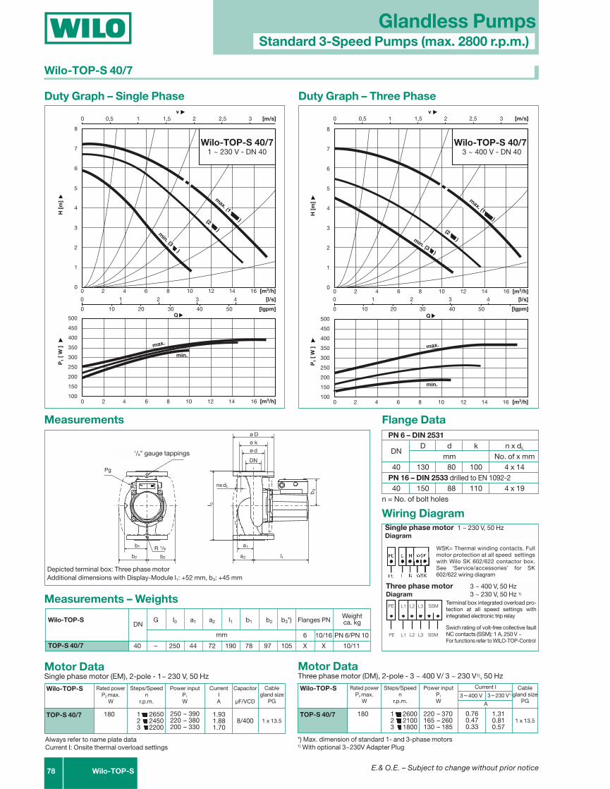
Wilo-TOP-S 40/71 ~ 230 V - DN 40
max. (1 )
min. (3 )
(2 )
PN 6 – DIN 2531
DND d k n x dL
mm No. of x mm40 130 080 100 4 x 14
PN 16 – DIN 2533 drilled to EN 1092-240 150 088 110 4 x 19
Flange Data
n = No. of bolt holes
TOP-S 40/7
l
b
DN
a
a
l
d
k
ø D
nxd
bb
b
Druckmeßanschlüsse R 1/8
R 1/8
0
1
2
3
L
22
1
øø
1
Pg
Measurements – Weights
Motor DataThree phase motor (DM), 2-pole - 3 ~ 400 V/ 3 ~ 230 V1), 50 Hz
Measurements
Duty Graph – Single Phase Duty Graph – Three Phase
Wilo-TOP-S
TOP-S 40/7
Rated powerP2 max.
W
180
Current I
0.760.470.33
3~230 V1)
Power inputP1
W
Steps/Speedn
r.p.m.
1 26002 21003 1800
500
450
400
350
300
250
200
150
100
0 1 2 3 4
0 10 20 30 40 50
0 0,5 1 1,5 2 2,5 3
0 2 4 6 8 10 12 14 16
0 2 4 6 8 10 12 14 16
v [m/s]
[m3/h]
P1
[ W
]H
[m
]Q
[m3/h]
[lgpm]
8
7
6
5
4
3
2
1
0
[l/s]
min.
Wilo-TOP-S 40/73 ~ 400 V - DN 40
min. (3 )
(2 )
max. (1 )
max.
Flanges PNWeightca. kgG I0 a1 a2 l1 b1 b2 b3*)
Motor DataSingle phase motor (EM), 2-pole - 1~ 230 V, 50 Hz
Wilo-TOP-S
TOP-S 40/7
Rated powerP2 max.
W
180
CurrentIA
Capacitor
µF/VCD
8/400
Power inputP1
W
Steps/Speedn
r.p.m.
1 26502 24503 2200
A
1.310.810.57
3~400 V
220 – 370165 – 260130 – 185
250 – 390220 – 380200 – 330
1.931.881.70
Cablegland size
PG
1 x 13.5
Cablegland size
PG
1 x 13.5
DNWilo-TOP-S
mm 6 10/16 PN 6/PN 10
40 – 250 44 72 190 78 97 105 X X 10/11
Wilo-TOP-S 40/7
Wiring Diagram
L1 L2 L3 SSM
L1 L2 L3 SSM
PE
PE
*) Max. dimension of standard 1- and 3-phase motors1) With optional 3~230V Adapter Plug
Always refer to name plate dataCurrent I: Onsite thermal overload settings
Depicted terminal box: Three phase motorAdditional dimensions with Display-Module l1: +52 mm, b3: +45 mm
1/8" gauge tappings
Single phase motor 1 ~ 230 V, 50 HzDiagram
Three phase motor 3 ~ 400 V, 50 HzDiagram 3 ~ 230 V, 50 Hz 1)
Terminal box integrated overload pro-tection at all speed settings withintegrated electronic trip relay
Swich rating of volt-free collective faultNC contacts (SSM): 1 A, 250 V ~For functions refer to WILO-TOP-Control
WSK= Thermal winding contacts. Fullmotor protection at all speed settingswith Wilo SK 602/622 contactor box.See ‘Service/accessories’ for SK602/622 wiring diagram

E.& O.E. – Subject to change without prior notice
6 10/16 PN 6/PN 10
40 – 250 57 88 214 90 115 110 X X 13/14
Glandless PumpsStandard 3-Speed Pumps (max. 2800 r.p.m.)
Wilo-TOP-S 79
Wilo-TOP-S 40/10
PN 6 – DIN 2531
DND d k n x dL
mm No. of x mm40 130 080 100 4 x 14
PN 16 – DIN 2533 drilled to EN 1092-240 150 088 110 4 x 19
Flange Data
n = No. of bolt holes
TOP-S 40/10
l
b
DN
a
a
l
dk
ø D
nxd
b
b
Druckmeßanschlüsse R 1/8
R 1/8
0
1
2
3
L
2
1
øø
1
Pg
b2
Measurements – Weights
Motor DataThree phase motor (DM), 2-pole - 3 ~ 400 V/ 3 ~ 230 V1), 50 Hz
Measurements
0 1 2 3 4 5
0 10 20 30 40 50 60 70
0 2 4 6 8 10 12 14 16 18
0 2 4 6 8 10 12 14 16 18 [m3/h]
P1
[ W
]H
[m
]
Q
[m3/h]
[lgpm]
600
500
400
300
200
100
0
12
11
10
9
8
7
6
5
4
3
2
1
0
[l/s]
max.
Wilo-TOP-S 40/103 ~ 400 V - DN 40
0 0,5 1 1,5 2 2,5 3 3,5 v
[m/s]
max. (1 )(2 )
min. (3 )
min.
Duty Graph – Three Phase
Wilo-TOP-S
TOP-S 40/10
Rated powerP2 max.
W
350
Current I
1.170.820.65
3~230 V1)
Power inputP1
W
Steps/Speedn
r.p.m.
1 28002 25003 2200
Flanges PNWeightca. kgG I0 a1 a2 l1 b1 b2 b3
A
2.021.431.12
3~400 V
300 – 585230 – 465200 – 365
Cablegland size
PG
1 x 13.5+1x Blind-stopfen
DNWilo-TOP-S
mm
Wiring Diagram
L1 L2 L3 SSM
L1 L2 L3 SSM
PE
PE
Three phase motor 3 ~ 400 V, 50 HzDiagram 3 ~ 230 V, 50 Hz 1)
Terminal box integrated overload protection at all speedsettings with integrated electronic trip relaySwich rating of volt-free collective fault NC contacts (SSM): 1 A, 250 V ~
For functions refer to WILO-TOP-Control
Always refer to name plate data!Current I: Onsite thermal overload settings1) With optional 3 ~ 230 V Adapter Plug
Additional dimensions with Display-Module l1: +52 mm, b3: +45 mm
1/8" gauge tappings
E.& O.E. – Subject to change without prior notice
6 10/16 PN 6/PN 10
50 – 240 51 80 197 93 112 105 X X 11/13
L1 L2 L3 SSM
L1 L2 L3 SSM
PE
PE
Glandless PumpsStandard 3-Speed Pumps (max. 2800 r.p.m.)
80 Wilo-TOP-S
PN 6 – DIN 2531
DND d k n x dL
mm No. of x mm50 140 090 110 4 x 14
PN 16 – DIN 2533 drilled to EN 1092-2
50 165 102 125 4 x 19
Flange Data
n = No. of bolt holes
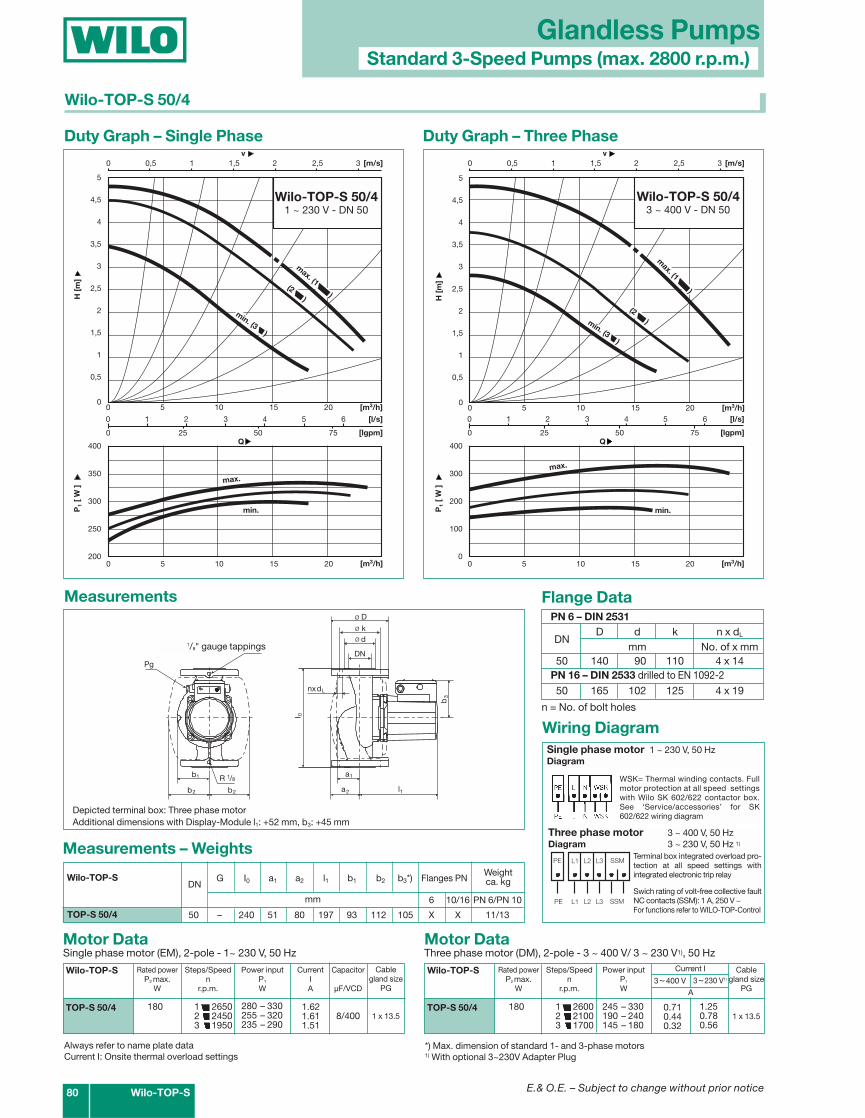
TOP-S 50/4
l
b
DN
a
a
l
dk
ø D
nxd
b
b
Druckmeßanschlüsse R 1/8
R 1/8
0
1
2
3
L
2
1
øø
1
Pg
b2
Measurements – Weights
Motor DataThree phase motor (DM), 2-pole - 3 ~ 400 V/ 3 ~ 230 V1), 50 Hz
Measurements
0 1 2 3 4 5 6
0 25 50 75
0 0,5 1 1,5 2 2,5 3
0 5 10 15 20
0 5 10 15 20
v [m/s]
[m3/h]
P1
[ W
]H
[m
]
Q
[m3/h]
[lgpm]
400
350
300
250
200
5
4,5
4
3,5
3
2,5
2
1,5
1
0,5
0
[l/s]
min.
Wilo-TOP-S 50/41 ~ 230 V - DN 50
max.
max. (1 )(2 )
min. (3 )
Duty Graph – Single Phase Duty Graph – Three Phase
Wilo-TOP-S
TOP-S 50/4
Rated powerP2 max.
W
180
Current I
0.710.440.32
3~230 V1)
Power inputP1
W
Steps/Speedn
r.p.m.
1 26002 21003 1700
400
300
200
100
0
0 5 10 15 20
0 5 10 15 20 [m3/h]
P1
[ W
]H
[m
]
[m3/h]
5
4,5
4
3,5
3
2,5
2
1,5
1
0,5
0
max.
min. (3 )
max. (1 )
Wilo-TOP-S 50/43 ~ 400 V - DN 50
min.
0 1 2 3 4 5 6
0 25 50 75Q
[lgpm]
[l/s]
0 0,5 1 1,5 2 2,5 3 v
[m/s]
(2 )
Flanges PNWeightca. kgG I0 a1 a2 l1 b1 b2 b3*)
Motor DataSingle phase motor (EM), 2-pole - 1~ 230 V, 50 Hz
Wilo-TOP-S
TOP-S 50/4
Rated powerP2 max.
W
180
CurrentIA
Capacitor
µF/VCD
8/400
Power inputP1
W
Steps/Speedn
r.p.m.
1 26502 24503 1950
A
1.250.780.56
3~400 V
245 – 330190 – 240145 – 180
280 – 330255 – 320235 – 290
1.621.611.51
Cablegland size
PG
1 x 13.5
Cablegland size
PG
1 x 13.5
DNWilo-TOP-S
mm
Wilo-TOP-S 50/4
Wiring Diagram
*) Max. dimension of standard 1- and 3-phase motors1) With optional 3~230V Adapter Plug
Always refer to name plate dataCurrent I: Onsite thermal overload settings
Depicted terminal box: Three phase motorAdditional dimensions with Display-Module l1: +52 mm, b3: +45 mm
1/8" gauge tappings
Single phase motor 1 ~ 230 V, 50 HzDiagram
Three phase motor 3 ~ 400 V, 50 HzDiagram 3 ~ 230 V, 50 Hz 1)
Terminal box integrated overload pro-tection at all speed settings withintegrated electronic trip relay
Swich rating of volt-free collective faultNC contacts (SSM): 1 A, 250 V ~For functions refer to WILO-TOP-Control
WSK= Thermal winding contacts. Fullmotor protection at all speed settingswith Wilo SK 602/622 contactor box.See ‘Service/accessories’ for SK602/622 wiring diagram
E.& O.E. – Subject to change without prior notice
Glandless PumpsStandard 3-Speed Pumps (max. 2800 r.p.m.)
Wilo-TOP-S 81
6 10/16 PN 6/PN 10
50 – 280 63 82 222 91 116 110 X X 14/16
50 – 280 69 91 219 101 120 110 X X 15/17
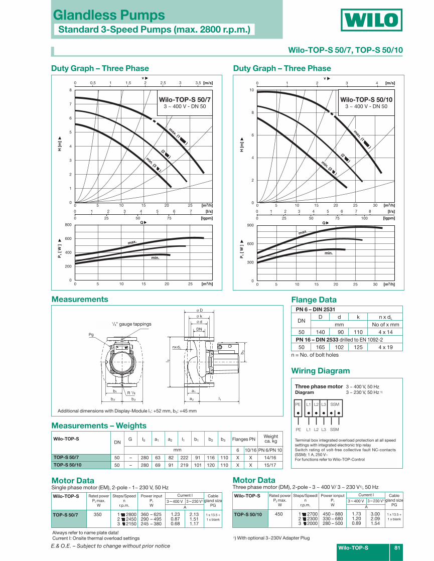
Wilo-TOP-S 50/7, TOP-S 50/10
PN 6 – DIN 2531
DND d k n x dL
mm No of x mm50 140 090 110 4 x 14
PN 16 – DIN 2533 drilled to EN 1092-250 165 102 125 4 x 19
Flange Data
n = No. of bolt holes
l
b
DN
a
a
l
dk
ø D
nxd
b
b
Druckmeßanschlüsse R 1/8
R 1/8
0
1
2
3
L
2
1
øø
1
Pg
b2
Motor DataSingle phase motor (EM), 2-pole - 1~ 230 V, 50 Hz
Measurements
0 1 2 3 4 5 6 7
0 25 50 75
0 0,5 1 1,5 2 2,5 3 3,5
0 5 10 15 20 25
0 5 10 15 20 25
v [m/s]
[m3/h]
P1
[ W
]H
[m
]
Q
[m3/h]
[lgpm]
800
600
400
200
0
8
7
6
5
4
3
2
1
0
[l/s]
min.
max.
Wilo-TOP-S 50/73 ~ 400 V - DN 50
min. (3 )
(2 )
max. (1 )
Duty Graph – Three Phase
Wilo-TOP-S
TOP-S 50/7
Rated powerP2 max.
W
350
Current I
1.230.870.68
3~230 V1)
Power inputP1
W
Steps/Speedn
r.p.m.
1 28002 24503 2150
A
2.131.511.17
3~400 V
360 – 625290 – 495245 – 380
Cablegland size
PG
1 x 13.5 +1 x blank
Measurements – Weights
Flanges PNWeightca. kgG I0 a1 a2 l1 b1 b2 b3DN
Wilo-TOP-S
mm
Motor DataThree phase motor (DM), 2-pole - 3 ~ 400 V/ 3 ~ 230 V1), 50 Hz
Wilo-TOP-S
TOP-S 50/10
Rated powerP2 max.
W
450
Current I
1.731.200.89
3~230 V1)
Power ionputP1
W
Steps/Speedln
r.p.m.
1 27002 23003 2000
A
3.002.091.54
3~400 V
450 – 880330 – 680280 – 500
Cablegland size
PG
1 x 13.5 +1 x blank
900
600
300
0
0 5 10 15 20 25 30
0 5 10 15 20 25 30 [m3/h]
P1
[ W
]H
[m
]
Q
[m3/h]
10
8
6
4
2
0
min.
0 1 2 3 4 5 6 7 8
0 25 50 75 100 [lgpm]
[l/s]
0 1 2 3 4v
[m/s]
Wilo-TOP-S 50/103 ~ 400 V - DN 50
max.
(2 )
max. (1 )
min. (3 )
Duty Graph – Three Phase
Wiring Diagram
L1 L2 L3 SSM
L1 L2 L3 SSM
PE
PE
Three phase motor 3 ~ 400 V, 50 HzDiagram 3 ~ 230 V, 50 Hz 1)
Terminal box integrated overload protection at all speedsettings with integrated electronic trip relaySwitch rating of volt-free collective fault NC-contacts(SSM): 1 A, 250 V~For functions refer to Wilo-TOP-Control
1) With optional 3~230V Adapter PlugAlways refer to name plate data!Current I: Onsite thermal overload settings
Additional dimensions with Display-Module l1: +52 mm, b3: +45 mm
TOP-S 50/7
TOP-S 50/10
1/8" gauge tappings
E.& O.E. – Subject to change without prior notice82 Wilo-TOP-S
PN 6/PN10 PN 6/PN 10
50 – 340 101 135 230 132 150 120 X 33.5TOP-S 50/15
a1
a2 l1
DN
l 0
b1
b2 b2
R1/8
Druckmeßanschlüsse R 1/8
Pg
b3
d Dk L1
k L 2
dL 1 dL 2
Zusatzmaße mit Displaymodul: l1: + max. 52 mm, b3: + max. 45 mm
nxdL
Measurements – Weights
Motor DataThree-phase motor (DM), 2-pole - 3 ~ 400 V/ 3 ~ 230 V1), 50 Hz
Measurements
1800
1600
1400
1200
1000
800
600
0 2 4 6 8 10
0 20 40 60 80 100 120
0 1 2 3 4
0 10 20 30
0 10 20 30
v [m/s]
[m3/h]
P1
[ W
]H
[m
]
Q
[m3/h]
[lgpm]
18
16
14
12
10
8
6
4
2
0
[l/s]
min.
max.
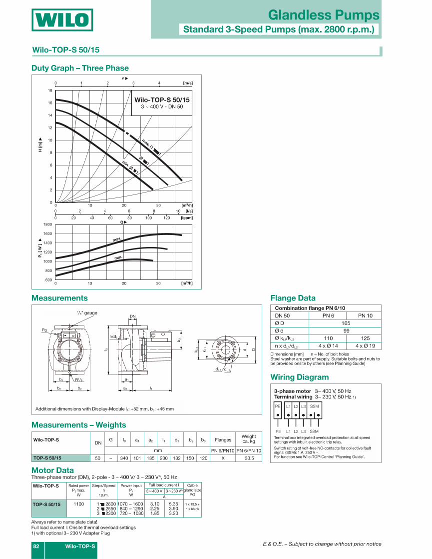
Wilo-TOP-S 50/153 ~ 400 V - DN 50
(2 )
max. (1 )
min. (3 )
Duty Graph – Three Phase
Wilo-TOP-S
TOP-S 50/15
Rated powerP2 max.
W
1100
Full load current I
3.102.251.85
3~230 V1)
Power inputP1
W
Steps/Speedn
r.p.m.
1 28002 25503 2300
FlangesWeightca. kgG I0 a1 a2 l1 b1 b2 b3
A
5.353.903.20
3~400 V
1070 – 1600840 – 1290720 – 1030
Cablegland size
PG
1 x 13.5 +1 x blank
DNWilo-TOP-S
mm
Wiring Diagram
L1 L2 L3 SSM
L1 L2 L3 SSM
PE
PE
3-phase motor 3~ 400 V, 50 HzTerminal wiring 3~ 230 V, 50 Hz 1)
Terminal box integrated overload protection at all speedsettings with inbuilt electronic trip relay.
Switch rating of volt-free NC-contacts for collective faultsignal (SSM): 1 A, 250 V ~.For function see Wilo-TOP-Control ‘Planning Guide’.
Always refer to name plate data!Full load current I: Onsite thermal overload settings1) with optional 3~ 230 V Adapter Plug
Glandless PumpsStandard 3-Speed Pumps (max. 2800 r.p.m.)
Wilo-TOP-S 50/15
Combination flange PN 6/10DN 50 PN 6 PN 10Ø D 165Ø d 99Ø kL1/kL2 110 125n x dL1/dL2 4 x Ø 14 4 x Ø 19
Flange Data
Dimensions [mm] n = No. of bolt holesSteel washer are part of supply. Suitable bolts and nuts tobe provided onsite by others (see Planning Guide)
Additional dimensions with Display-Module l1: +52 mm, b3: +45 mm
1/8" gauge
E.& O.E. – Subject to change without prior notice Wilo-TOP-S 83
PN 6 – DIN 2531
DND d k n x dL
mm No. of x mm65 160 110 130 4 x 14
PN 16 – DIN 2533 drilled to EN 1092-265 185 122 145 4 x 19
Flange Data
n = No. of bolt holes
l
b
DN
a
a
l
dk
ø D
nxd
b
b
Druckmeßanschlüsse R 1/8
R 1/8
0
1
2
3
L
2
1
øø
1
Pg
b2
Motor DataThree phase motor (DM), 2-pole - 3 ~ 400 V/ 3 ~ 230 V1), 50 Hz
Measurements
Wilo-TOP-S
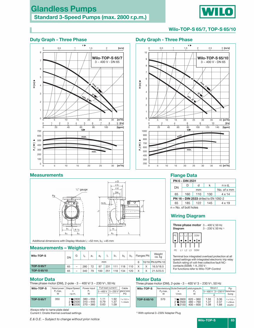
TOP-S 65/7
Rated powerP2 max.
W
350
Full load current I
1.110.790.63
3~230 V1)
Power inputP1
W
Steps/Speedn
r.p.m.
1 28002 25003 2200
A
1.921.371.09
3~400 V
380 – 550310 – 445270 – 360
Cablegland size
PG
1 x 13.5 +1 x blank
0 1 2 3 4 5 6 7 8 9
0 20 40 60 80 100
0 0,5 1 1,5 2
0 5 10 15 20 25 30
0 5 10 15 20 25 30
v [m/s]
[m3/h]
P1
[ W
]H
[m
]
Q
[m3/h]
[lgpm]
700
600
500
400
300
200
100
0
8
7
6
5
4
3
2
1
0
[l/s]
min.
Wilo-TOP-S 65/73 ~ 400 V - DN 65
max.
min. (3 )
(2 )
max. (1 )
Duty Graph - Three Phase Duty Graph - Three Phase
1000
900
800
700
600
500
400
300
200
0 2 4 6 8 10
0 20 40 60 80 100 120 140
0 0,5 1 1,5 2 2,5 3
0 5 10 15 20 25 30 35 40
0 5 10 15 20 25 30 35 40
v [m/s]
[m3/h]
P1
[ W
]H
[m
]
Q
[m3/h]
[lgpm]
10
9
8
7
6
5
4
3
2
1
0
[l/s]
min.
Wilo-TOP-S 65/103 ~ 400 V - DN 65
max.
(2 )min. (3 )
max. (1 )
Motor DataThree phase motor (DM), 2-pole - 3 ~ 400 V/ 3 ~ 230 V1), 50 Hz
Wilo-TOP-S
TOP-S 65/10
NennleistungP2 max.
W
570
Strom I
1.941.371.08
3~230 V1)
Leistungsaufn.P1W
Stufe/Drehzahln
1/min
1 28002 25003 2150
A
3.362.371.88
3~400 V
620 – 960480 – 760400 – 600
Pg-Verschrau-
bung
1 x 13.5 +1 x Blind-stopfen
6 10/16 PN 6/PN 10
65 – 280 72 97 231 111 118 110 X X 16.5/18.5
65 – 340 79 100 251 118 134 120 X X 21.5/23.5
TOP-S 65/7
TOP-S 65/10
Measurements – Weights
Flanges PNWeightca. kgG I0 a1 a2 l1 b1 b2 b3DN
Wilo-TOP-S
mm
Wiring Diagram
L1 L2 L3 SSM
L1 L2 L3 SSM
PE
PE
Three phase motor 3 ~ 400 V, 50 HzDiagram 3 ~ 230 V, 50 Hz 1)
Terminal box integrated overload protection at allspeed settings with integrated electronic trip relaySwitch rating of volt-free collective fault NC-contacts (SSM): 1 A, 250 V~For functions refer to Wilo-TOP-Control
1) With optional 3~230V Adapter PlugAlways refer to name plate data!Current I: Onsite thermal overload settings
Additional dimensions with Display-Module l1: +52 mm, b3: +45 mm
Glandless PumpsStandard 3-Speed Pumps (max. 2800 r.p.m.)
Wilo-TOP-S 65/7, TOP-S 65/10
1/8" gauge
6 10/16 PN 6/PN 10
65 – 340 79 100 251 118 134 120 X X 23.5/25.5
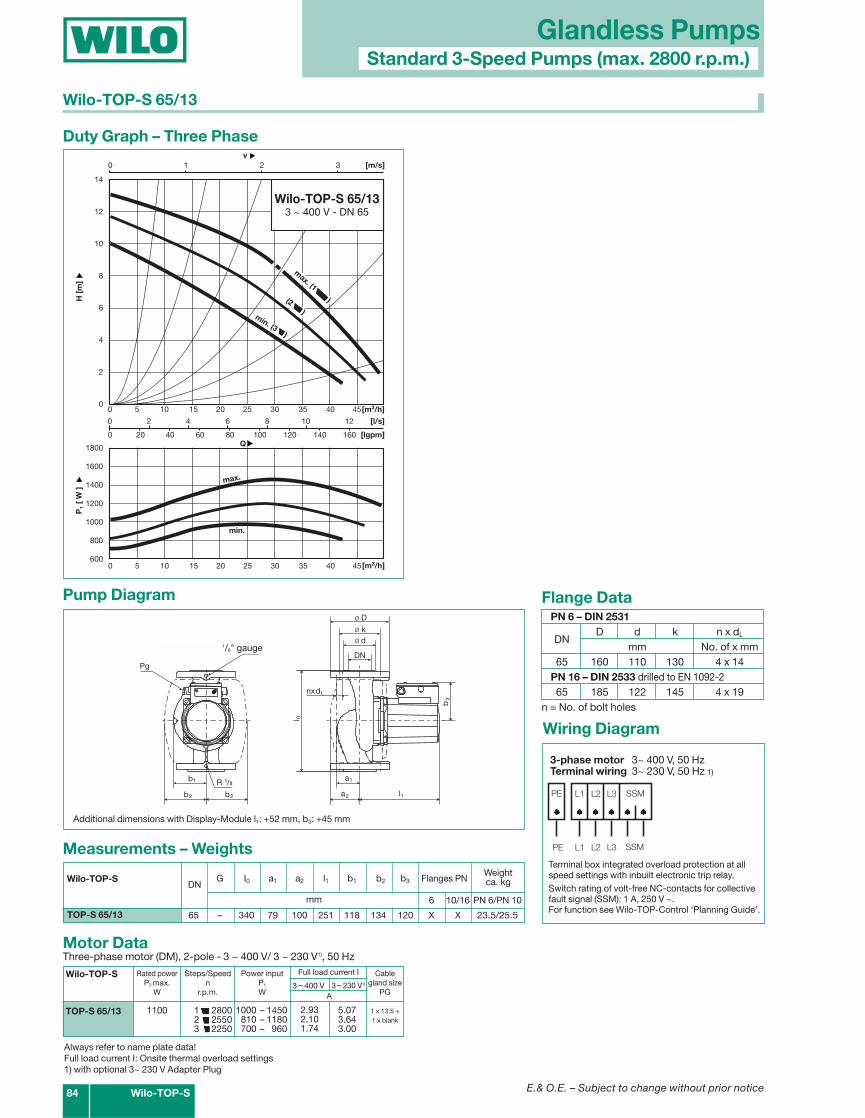
PN 6 – DIN 2531
DND d k n x dL
mm No. of x mm65 160 110 130 4 x 14
PN 16 – DIN 2533 drilled to EN 1092-265 185 122 145 4 x 19
Flange Data
n = No. of bolt holes
TOP-S 65/13
l
b
DN
a
a
l
dk
ø D
nxd
b
b
Druckmeßanschlüsse R 1/8
R 1/8
0
1
2
3
L
2
1
øø
1
Pg
b2
Measurements – Weights
Motor DataThree-phase motor (DM), 2-pole - 3 ~ 400 V/ 3 ~ 230 V1), 50 Hz
Pump Diagram
0 2 4 6 8 10 12
0 20 40 60 80 100 120 140 160
0 1 2 3
0 5 10 15 20 25 30 35 40 45
0 5 10 15 20 25 30 35 40 45
v [m/s]
[m3/h]
P1
[ W
]H
[m
]
Q
[m3/h]
[lgpm]
1800
1600
1400
1200
1000
800
600
14
12
10
8
6
4
2
0
[l/s]
min.
Wilo-TOP-S 65/133 ~ 400 V - DN 65
max.
min. (3 )
(2 )
max. (1 )
Duty Graph – Three Phase
Wilo-TOP-S
TOP-S 65/13
Rated powerP2 max.
W
1100
Full load current I
2.932.101.74
3~230 V1)
Power inputP1
W
Steps/Speedn
r.p.m.
1 28002 25503 2250
Flanges PNWeightca. kgG I0 a1 a2 l1 b1 b2 b3
A
5.073.643.00
3~400 V
1000 – 1450810 – 1180700 – 960
Cablegland size
PG
1 x 13.5 +1 x blank
DNWilo-TOP-S
mm
Wiring Diagram
L1 L2 L3 SSM
L1 L2 L3 SSM
PE
PE
3-phase motor 3~ 400 V, 50 HzTerminal wiring 3~ 230 V, 50 Hz 1)
Terminal box integrated overload protection at allspeed settings with inbuilt electronic trip relay.Switch rating of volt-free NC-contacts for collectivefault signal (SSM): 1 A, 250 V ~.For function see Wilo-TOP-Control ‘Planning Guide’.
Always refer to name plate data!Full load current I: Onsite thermal overload settings1) with optional 3~ 230 V Adapter Plug
Additional dimensions with Display-Module l1: +52 mm, b3: +45 mm
84 Wilo-TOP-S
Glandless PumpsStandard 3-Speed Pumps (max. 2800 r.p.m.)
Wilo-TOP-S 65/13
1/8" gauge
E.& O.E. – Subject to change without prior notice
PN 6/PN 10 PN 6/PN10
65 – 340 79 100 278 118 134 120 X 29TOP-S 65/15
a1
a2 l1
DN
l 0
b1
b2 b2
R1/8
Druckmeßanschlüsse R 1/8
Pg
b3
d Dk L1
k L 2
dL 1 dL 2
Zusatzmaße mit Displaymodul: l1: + max. 52 mm, b3: + max. 45 mm
nxdL
Measurements – Weights
Motor DataThree-phase motor (DM), 2-pole - 3 ~ 400 V/ 3 ~ 230 V1), 50 Hz
Pump Diagram
1800
1600
1400
1200
1000
800
600
0 2 4 6 8 10 12 14
0 20 40 60 80 100 120 140 160 180
0 0,5 1 1,5 2 2,5 3 3,5 4
0 10 20 30 40 50
0 10 20 30 40 50
v [m/s]
[m3/h]
P1
[ W
]H
[m
]
Q
[m3/h]
[lgpm]
16
14
12
10
8
6
4
2
0
[l/s]
min.
max.
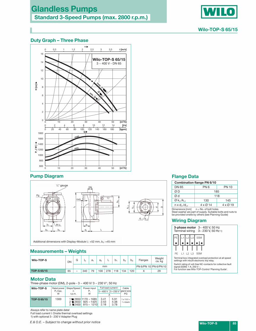
Wilo-TOP-S 65/153 ~ 400 V - DN 65
max. (1 )(2 )
min. (3 )
Duty Graph – Three Phase
Wilo-TOP-S
TOP-S 65/15
Rated powerP2 max.
W
1300
Full load current I
3.412.532.18
3~230 V1)
Power inputP1
W
Steps/Speedn
r.p.m.
1 28502 26503 2400
FlangesWeightca. kgG I0 a1 a2 l1 b1 b2 b3
A
5.914.383.78
3~400 V
1170 – 1685925 – 1425815 – 1210
Cablegland size
PG
1 x 13.5 +1 x blank
DNWilo-TOP-S
mm
Wiring Diagram3-phase motor 3~ 400 V, 50 HzTerminal wiring 3~ 230 V, 50 Hz 1)
Terminal box integrated overload protection at all speedsettings with inbuilt electronic trip relay.
Switch rating of volt-free NC-contacts for collective faultsignal (SSM): 1 A, 250 V ~.For function see Wilo-TOP-Control ‘Planning Guide’.
Always refer to name plate data!Full load current I: Onsite thermal overload settings1) with optional 3~ 230 V Adapter Plug
Wilo-TOP-S 85
Glandless PumpsStandard 3-Speed Pumps (max. 2800 r.p.m.)
Wilo-TOP-S 65/15
Combination flange PN 6/10DN 65 PN 6 PN 10Ø D 185Ø d 118Ø kL1/kL2 130 145n x dL1/dL2 4 x Ø 14 4 x Ø 19
Flange Data
Dimensions [mm] n = No. of bolt holesSteel washer are part of supply. Suitable bolts and nuts tobe provided onsite by others (see Planning Guide)
Additional dimensions with Display-Module l1: +52 mm, b3: +45 mmL1 L2 L3 SSM
L1 L2 L3 SSM
PE
PE
E.& O.E. – Subject to change without prior notice
1/8" gauge
E.& O.E. – Subject to change without prior notice
6 10/16 PN 6/PN 10
80 – 360 96 130 225 111 135 110 X X 23.5/25.5
80 – 360 95 130 253 135 152 120 X X 28/30
mm
Glandless PumpsStandard 3-Speed Pumps (max. 2800 r.p.m.)
86 Wilo-TOP-S
1800
1600
1400
1200
1000
800
0 3 6 9 12 15
0 50 100 150
0 0,5 1 1,5 2 2,5 3
0 10 20 30 40 50 60
0 10 20 30 40 50 60
v [m/s]
[m3/h]
P1
[W]
H [
m]
Q
[m3/h]
[lgpm]
12
11
10
9
8
7
6
5
4
3
2
1
0
[l/s]
min.
Wilo-TOP-S 80/103 ~ 400 V - DN 80
(2 )
max. (1 )
min. (3 )
max.
Duty Graph – Three Phase
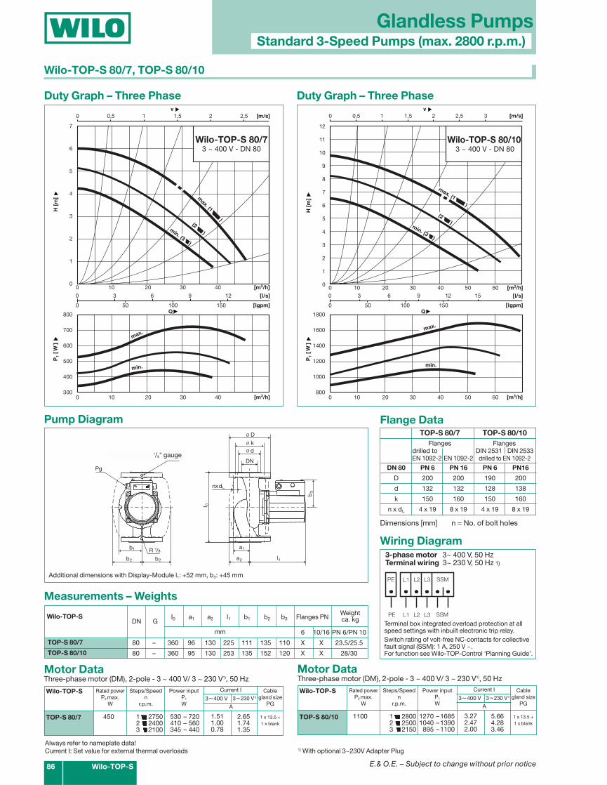
Wilo-TOP-S 80/7, TOP-S 80/10
TOP-S 80/7 TOP-S 80/10Flanges Flanges
drilled to DIN 2531 DIN 2533EN 1092-2 EN 1092-2 drilled to EN 1092-2
DN 80 PN 6 PN 16 PN 6 PN16
D 200 200 190 200
d 132 132 128 138
k 150 160 150 160
n x dL 4 x 19 8 x 19 4 x 19 8 x 19
Flange Data
Dimensions [mm] n = No. of bolt holes
l
b
DN
a
a
l
dk
ø D
nxd
b
b
Druckmeßanschlüsse R 1/8
R 1/8
0
1
2
3
L
2
1
øø
1
Pg
b2
Motor DataThree-phase motor (DM), 2-pole - 3 ~ 400 V/ 3 ~ 230 V1), 50 Hz
Pump Diagram
0 3 6 9 12
0 50 100 150
0 0,5 1 1,5 2 2,5
0 10 20 30 40
0 10 20 30 40
v [m/s]
[m3/h]
P1
[W]
H [
m]
Q
[m3/h]
[lgpm]
800
700
600
500
400
300
7
6
5
4
3
2
1
0
[l/s]
min.
Wilo-TOP-S 80/73 ~ 400 V - DN 80
max.
max. (1 )
min. (3 )
(2 )
Duty Graph – Three Phase
Wilo-TOP-S
TOP-S 80/7
Rated powerP2 max.
W
450
Current I
1.511.000.78
3~230 V1)
Power inputP1
W
Steps/Speedn
r.p.m.
1 27502 24003 2100
A
2.651.741.35
3~400 V
530 – 720410 – 560345 – 440
Cablegland size
PG
1 x 13.5 +1 x blank
Motor DataThree-phase motor (DM), 2-pole - 3 ~ 400 V/ 3 ~ 230 V1), 50 Hz
Wilo-TOP-S
TOP-S 80/10
Rated powerP2 max.
W
1100
Current I
3.272.472.00
3~230 V1)
Power inputP1
W
Steps/Speedn
r.p.m.
1 28002 25003 2150
A
5.664.283.46
3~400 V
1270 –16851040 –1390895 –1100
Cablegland size
PG
1 x 13.5 +1 x blank
TOP-S 80/7
TOP-S 80/10
Flanges PNWeightca. kg
Measurements – Weights
G I0 a1 a2 l1 b1 b2 b3DN GWilo-TOP-S
Wiring Diagram
L1 L2 L3 SSM
L1 L2 L3 SSM
PE
PE
3-phase motor 3~ 400 V, 50 HzTerminal wiring 3~ 230 V, 50 Hz 1)
Terminal box integrated overload protection at allspeed settings with inbuilt electronic trip relay.Switch rating of volt-free NC-contacts for collectivefault signal (SSM): 1 A, 250 V ~.For function see Wilo-TOP-Control ‘Planning Guide’.
1) With optional 3~230V Adapter PlugAlways refer to nameplate data!Current I: Set value for external thermal overloads
Additional dimensions with Display-Module l1: +52 mm, b3: +45 mm
1/8" gauge
E.& O.E. – Subject to change without prior notice
Glandless Pumps
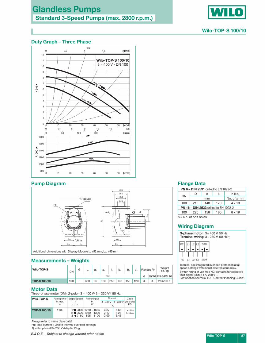
Wilo-TOP-S 100/10
Wilo-TOP-S 87
Standard 3-Speed Pumps (max. 2800 r.p.m.)
PN 6 – DIN 2531 drilled to EN 1092-2
DND d k n x dL
mm No. of x mm100 210 148 170 4 x 19PN 16 – DIN 2533 drilled to EN 1092-2100 220 158 180 8 x 19
Flange Data
n = No. of bolt holes
l
b
DN
a
a
l
dk
ø D
nxd
b
b
Druckmeßanschlüsse R 1/8
R 1/8
0
1
2
3
L
2
1
øø
1
Pg
b2
Pump Diagram
0 0,5 1 1,5 2v
[m/s]
1800
1600
1400
1200
1000
800
0 3 6 9 12 15
0 50 100 150
0 10 20 30 40 50 60
0 10 20 30 40 50 60 [m3/h]
P1
[W]
H [
m]
Q
[m3/h]
[lgpm]
12
11
10
9
8
7
6
5
4
3
2
1
0
[l/s]
min.
max.
(2 )
max. (1 )
min. (3 )
Duty Graph – Three Phase
Motor DataThree-phase motor (DM), 2-pole - 3 ~ 400 V/ 3 ~ 230 V1), 50 Hz
Wilo-TOP-S
TOP-S 100/10
Rated powerP2 max.
W
1100
Current I
3.272.472.00
3~230 V1)
Power inputP1
W
Steps/Speedn
r.p.m.
1 28002 25003 2150
A
5.664.283.46
3~400 V
1270 –16851040 –1390895 –1100
Cablegland size
PG
1 x 13.5 +1 x blank
6 10/16 PN 6/PN 10
100 – 360 95 130 253 135 152 120 X X 28.5/30.5TOP-S 100/10
Measurements – Weights
Flanges PNWeightca. kgG I0 a1 a2 l1 b1 b2 b3DN
Wilo-TOP-S
mm
Wiring Diagram
L1 L2 L3 SSM
L1 L2 L3 SSM
PE
PE
3-phase motor 3~ 400 V, 50 HzTerminal wiring 3~ 230 V, 50 Hz 1)
Terminal box integrated overload protection at allspeed settings with inbuilt electronic trip relay.Switch rating of volt-free NC-contacts for collectivefault signal (SSM): 1 A, 250 V ~.For function see Wilo-TOP-Control ‘Planning Guide’.
Always refer to name plate data!Full load current I: Onsite thermal overload settings1) with optional 3~ 230 V Adapter Plug
Additional dimensions with Display-Module l1: +52 mm, b3: +45 mm
Wilo-TOP-S 100/103 ~ 400 V - DN 100
1/8" gauge