Embed Size (px)
Citation preview
8/14/2019 Wika DG10E Catalog
http://slidepdf.com/reader/full/wika-dg10e-catalog 1/4
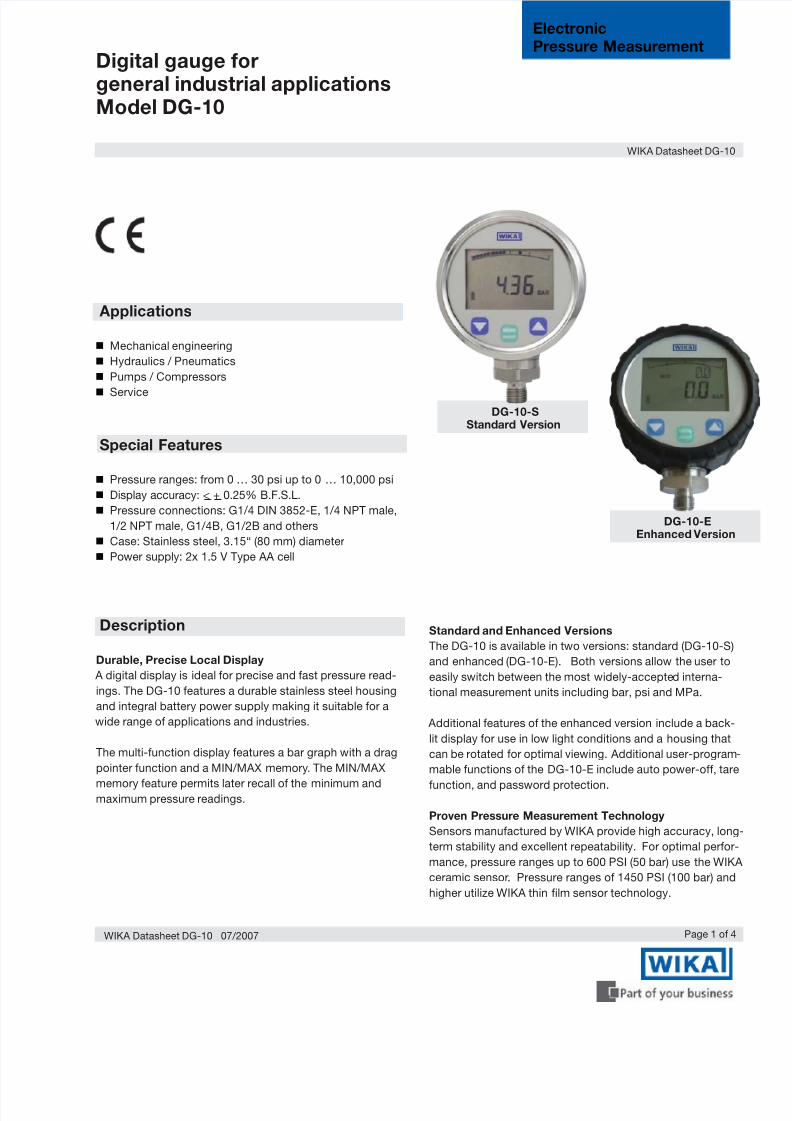
Digital gauge forgeneral industrial applicationsModel DG-10
Page 1 of 4
ElectronicPressure Measurement
WIKA Datasheet DG-10
Mechanical engineering
Hydraulics / Pneumatics
Pumps / Compressors
Service
Pressure ranges: from 0 … 30 psi up to 0 … 10,000 psi
Display accuracy: < + 0.25% B.F.S.L.
Pressure connections: G1/4 DIN 3852-E, 1/4 NPT male,
1/2 NPT male, G1/4B, G1/2B and others
Case: Stainless steel, 3.15“ (80 mm) diameter
Power supply: 2x 1.5 V Type AA cell
DG-10-SStandard Version
DG-10-EEnhanced Version
Applications
Durable, Precise Local Display
A digital display is ideal for precise and fast pressure read-
ings. The DG-10 features a durable stainless steel housing
and integral battery power supply making it suitable for a
wide range of applications and industries.
The multi-function display features a bar graph with a drag
pointer function and a MIN/MAX memory. The MIN/MAX
memory feature permits later recall of the minimum andmaximum pressure readings.
Standard and Enhanced Versions
The DG-10 is available in two versions: standard (DG-10-S)
and enhanced (DG-10-E). Both versions allow the user to
easily switch between the most widely-accepted interna-
tional measurement units including bar, psi and MPa.
Additional features of the enhanced version include a back-
lit display for use in low light conditions and a housing that
can be rotated for optimal viewing. Additional user-program-
mable functions of the DG-10-E include auto power-off, tare
function, and password protection.
Proven Pressure Measurement Technology
Sensors manufactured by WIKA provide high accuracy, long
term stability and excellent repeatability. For optimal perfor-
mance, pressure ranges up to 600 PSI (50 bar) use the WIKA
ceramic sensor. Pressure ranges of 1450 PSI (100 bar) and
higher utilize WIKA thin film sensor technology.
Description
Special Features
WIKA Datasheet DG-10 07/2007

8/14/2019 Wika DG10E Catalog
http://slidepdf.com/reader/full/wika-dg10e-catalog 2/4
Page 2 of 4
{ } Items in curved brackets are optional extras for additional price.
WIKA Datasheet DG-10 07/2007
Specifications Model DG-10
Pressure ranges psi -30 INHG ... 29 psi -30 INHG ... 72 psi -30 INHG ... 145 psi
Over pressure safety psi 70 145 290
Burst pressure psi 85 170 360
Pressure ranges psi 30 60 145 300 600 1450
Over pressure safety psi 70 145 290 580 1450 2900
Burst pressure psi 85 170 360 725 1740 11600
Pressure ranges psi 2000 3000 5000 7500 10000
Over pressure safety psi 4640 7250 11600 17400 21750
Burst pressure psi 14500 17400 24650 34800 43500
Materials
■ Wetted parts
» Pressure connection 1.4571, Stainless steel 316TI
» Pressure sensor Ceramic Al2O
396%, NBR {EPDM } (up to 0 ... 600 psi)
XM-13 (1.4534) (> 1450 psi)
■ Case 1.4301, Stainless steel 304
Power supply 2x 1.5 V Type AA batteries
Operating time h 4000 (AA 2000 mAh)
Internal sampling rate ms 200
Insulation voltage VDC 500
Display accuracy % of span ≤ ± 0.25% B.F.S.L.
Zero Offset % of span ≤ 0.1 (Power-up reset)
Zero adjustability % of span ≤ 20 (via Tare-Function with model DG-10-E)
Hysteresis % of span ≤ 0.1
Non-repeatability % of span ≤ 0.1
Long-term stability per year % of span ≤ 0.2
Long-term drift % of span ≤ 0.1
Permissible temperature of
■ Medium -4°F ... +185°F (-20°C ... +85°C) (up to 0 ... 600 psi)
-22°F ... +212°F (-30°C ... +100°C) (> 1450 psi)
■ Ambient +14°F ... +140°F (-10°C ... +60°C)
■ Storage -4°F ... +158°F (-20°C ... +70°C)
Operating temperature range +32°F ... +140°F (0°C ... +60°C)
Temperature coefficients within
compensated temp range■ Mean TC of zero % of span ≤ 0.15 / 10k
■ Mean TC of span % of span ≤ 0.15 / 10k
CE-conformity
■ Pressure equipment directive 97/23/EC
■ EMC directive 89/336/EEC emission (class B) and immunity according to EN 61 326
Case rotation ° 300 ° (only with model DG-10-E)
DG-10-S DG-10-E
Principle 7 segment LCD 4 digit 7 segment LCD 4 1/2 digit
14 segment LCD 4 1/2 digit (2nd display)
Digit size .43“ (11 mm) .43 (11 mm) and .28“ (7 mm)
Display -999 ... 9999 -1999 ... 19999
Background illumination No Included
Bar graph with trailing pointer Included Included
function
Min/Max memory Included Included
Auto On/Off Optional (ex works) 15/30/60/120 min
Tare adjustment No Included
Units bar, psi, MPa Included Included
Password protection No Included
Reset factory setting No Included
Weight Approx. 14oz. (400 g)
8/14/2019 Wika DG10E Catalog
http://slidepdf.com/reader/full/wika-dg10e-catalog 3/4
Page 3 of 4 WIKA Datasheet DG-10 07/2007
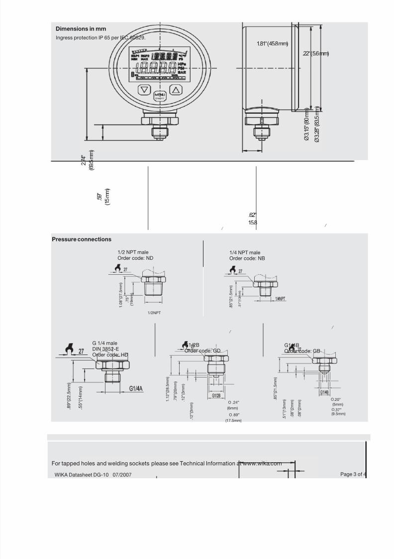
Dimensions in mm
Ingress protection IP 65 per IEC 60529.
Pressure connections
For tapped holes and welding sockets please see Technical Information at www.wika.com
1.81“ (45.8 mm)
.22“ (5.6 mm)
.62"
15.8
Ø 3 . 1
5 " ( 8 0 m m )
Ø 3 . 2
8 " ( 8 3 . 5 m m )
2 . 7
4 "
( 6 9 . 5 m m )
. 5 9 "
( 1 5 m
m )
1 . 0
8 ” ( 2 7 . 5 m m )
. 7 5 ”
( 1 9 m m )
1/2NPT
. 8 5 ” ( 2 1 . 5
m m )
. 5 1 ” ( 1 3 m m
)
1/2 NPT maleOrder code: ND
1/4 NPT maleOrder code: NB
G 1/4 maleDIN 3852-EOrder code: HD
. 5 5 “ ( 1 4 m m )
. 8 9 “ ( 2 2 . 5 m m )
1 . 1
2 ” ( 2 8 . 5 m m )
. 7 9 ” ( 2 0 m m )
. 1 2 ” ( 3 m m )
. 1 2 ” ( 3 m m ) .24”
(6mm)
.69”
(17.5mm)
. 8 5 ” ( 2
1 . 5 m m )
. 5 1 ” ( 1 3 m m )
. 0 8 ” ( 2 m m )
. 0 8 ” ( 2 m m ) .20”
(5mm)
.37”(9.5mm)
O
O
O
O
G1/2BOrder code: GD
G1/4BOrder code: GB
8/14/2019 Wika DG10E Catalog
http://slidepdf.com/reader/full/wika-dg10e-catalog 4/4
WIKA Instrument Corporation
1000 Wiegand Boulevard
Lawrenceville, GA 30043-5868
Tel: 888-WIKA-USA • 770-513-8200
Fax: 770-338-5118
E-Mail: [email protected] www.wika.com
WIKA Datasheet DG-10 07/2007Page 4 of 4
Specifications and dimensions given in this data sheet represent the state of engineering at the time of printing.Modifications may take place and materials specified may be replaced by others without prior notice.
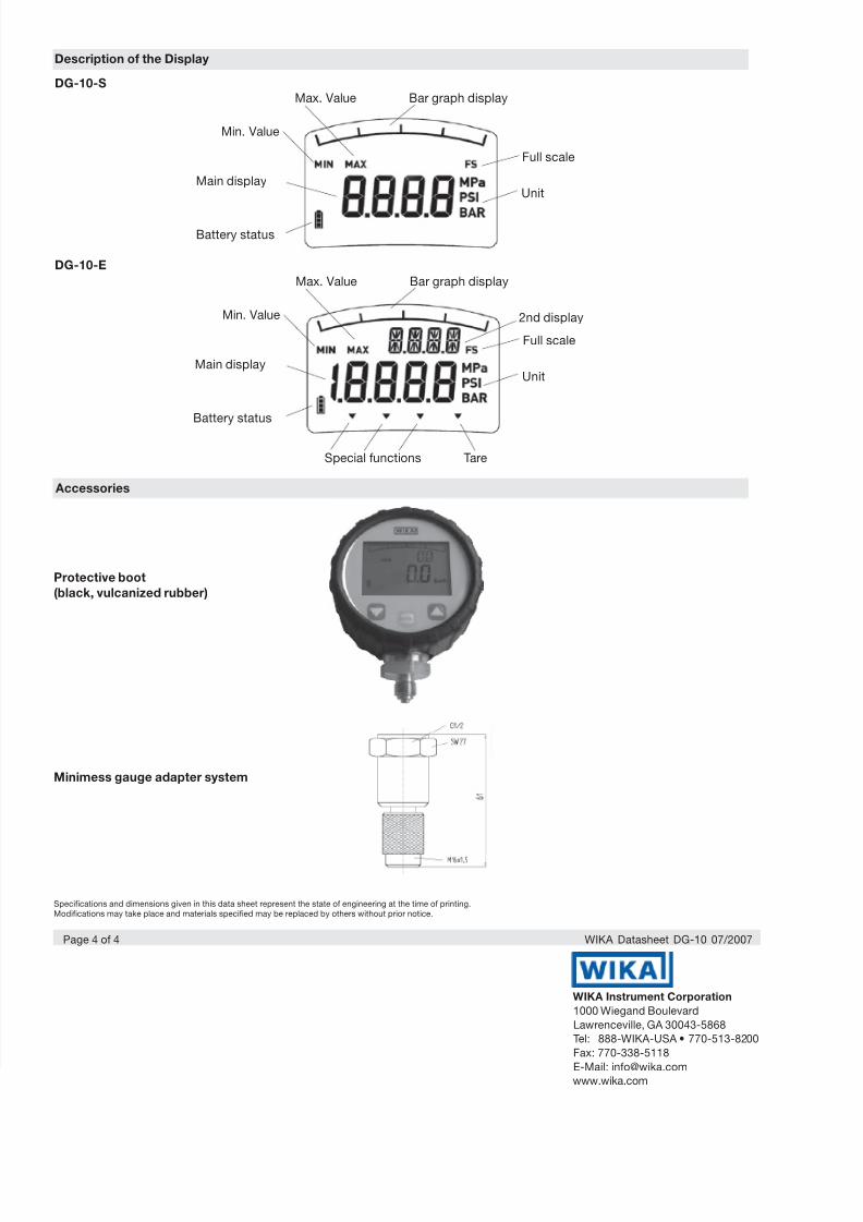
Description of the Display
DG-10-S
DG-10-E
Max. Value
Min. Value
Main display
Battery status
Bar graph display
Full scale
Unit
Max. Value
Min. Value
Main display
Battery status
Bar graph display
Full scale
Unit
Special functions Tare
2nd display
Protective boot
(black, vulcanized rubber)
Accessories
Minimess gauge adapter system


![WIKA Instruments Limited - Company presentation A · PDF fileA strong group. For your success. WIKA Instruments Limited - Company presentation 1 [16.01.2018] WIKA Instruments Company](https://img.pdfslide.us/doc/110x75/5a9e4a607f8b9a6a218d40e6/wika-instruments-limited-company-presentation-a-a-strong-group-for-your.jpg)