Embed Size (px)
Citation preview

Why Do Protein Crystals Grown With the Aid ofPorous Materials Show Better Diffraction Quality?Christo N. Nanev
Bulgarian Academy of SciencesEmmanuel Saridakis
National Centre for Scienti�c Research “Demokritos”Lata Govada
Imperial College LondonNaomi E. Chayen ( [email protected] )
Imperial College London
Research Article
Keywords: Well-diffracting protein crystals, X-ray diffraction analysis, porous materials, better diffractionquality, Protein Data Bank
Posted Date: November 1st, 2021
DOI: https://doi.org/10.21203/rs.3.rs-1027122/v1
License: This work is licensed under a Creative Commons Attribution 4.0 International License. Read Full License
1
Why do protein crystals grown with the aid of porous materials show better
diffraction quality?
Christo N. Nanev1, Emmanuel Saridakis2, Lata Govada3 & Naomi E. Chayen3
1Rostislaw Kaischew Institute of Physical Chemistry, Bulgarian Academy of Sciences, Acad. G.
Bonchev Str. Bl. 11, 1113 Sofia, Bulgaria.
2Structural and Supramolecular Chemistry Laboratory, Institute of Nanoscience and Nanotechnology,
National Centre for Scientific Research “Demokritos”, Athens 15310, Greece.
3Computational and Systems Medicine, Department of Metabolism, Digestion and Reproduction,
Faculty of Medicine, Imperial College London, London SW7 2AZ, UK.
Correspondence and requests for materials should be addressed to C.N.N. (email:
[email protected]); or N.E.C. (email: [email protected])
Abstract: Well-diffracting protein crystals are indispensable for X-ray diffraction analysis,
which is still the most powerful method for structure-function studies of biomolecules. A
promising approach to growing such crystals is by using porous nucleation-inducing
materials. However, while protein crystal nucleation in pores has been thoroughly considered,
little attention has been paid to the subsequent growth of the crystals. Although the nucleation
stage is decisive, it is the subsequent growth of the crystals outside the pore that determines
their diffraction quality. The molecular-scale mechanism of growth of protein crystals in and
outside pores is here considered theoretically. Due to the metastable conditions, the crystals
that emerge from the pores grow slowly, which is a prerequisite for better diffraction. This
expectation has been corroborated by experiments carried out with several types of porous
material, such as Bioglass (“Naomi’s Nucleant”), Buckypaper, porous gold and porous
silicon. Protein crystals grown with the aid of Bioglass and Buckypaper yielded significantly
better diffraction quality compared with crystals grown conventionally. In all cases, visually
superior crystals are usually obtained. We furthermore conclude that heterogeneous
nucleation of a crystal outside the pore is an exceptional case. Rather, the protein crystals
nucleating inside the pores continue growing outside them.

2
1. Introduction
X-ray diffraction studies account for 89% of structures deposited in the Protein Data Bank
and, in most cases, continue to provide significantly higher resolution than other techniques,
such as nuclear magnetic resonance and cryo-electron microscopy. However, well-diffracting
protein crystals are notoriously difficult to produce. Porous materials help to mitigate this
problem [1-11]; the synergetic effect of diffusion in the confined pore space and protein
adsorption on pore walls can ensure a local supersaturation increase that is just sufficient for
crystal nucleation to occur, whereas very high supersaturation is highly unlikely to be
achieved [12]. Because the nucleation of crystals makes the difference between success and
failure of the crystallization attempts, nucleation of protein crystals in pores was considered
first, e.g. see [13]. That work has shown that to get 3D crystals it is vital to have 2D crystals
nucleating first; protein layers of monomolecular thickness formed in pores can become a
completely stable (i.e. destined to grow) crystal nucleus when the cohesive energy ΔGv (that
maintains the integrity of a crystalline cluster) and the destructive energy ΔGs (tending to tear
it up) become equal. However, relatively little attention was paid to the subsequent growth of
the nucleated crystals. In [13] it was noted merely that “once nucleated, such crystallites
continue their growth outside the pore orifice, forming 3D crystals.”
The aim of this paper is to consider the molecular-scale mechanism of growth of
protein crystals in pores and outside them. It has been shown that the growth process is
favored energetically in both cases – inside and outside the pore. Thus, it proceeds
spontaneously, i.e., without the need for forming 3D nuclei, neither inside nor outside the
pore. Most importantly however, this analysis explains why the use of porous materials as
nucleants contributes to the growth of protein crystals of better diffraction quality.
2. Results
Growth of protein crystals in pores. There is a significant difference in the growth of
crystals in the confined space of the pores and in the free space outside them. In the former
case, only the volume of the crystals increases, whereas their exposed surfaces (which are
subjected to the destructive action of the water molecules) remain constant - the pore size
hardly changes on a molecular distance. This means that ΔGs remains constant. In contrast,

3
both crystal volume and surface are constantly increasing during the growth of a crystal
outside the pore.
After the formation of a stable 2D nucleus, its growth begins with the addition of
molecules that are connected simultaneously to the wall of the capillary and to the lowest
crystal layer (i.e., the stable 2D nucleus itself). The following molecules are then bound
simultaneously to these and to the lowest crystal layer. This enables the continuous growth of
the crystal in the pore and finally, a completed protein layer of monomolecular thickness is
deposited upon the existing stable 2D crystal nucleus.
Let us consider the simplest crystal lattice, which is the so-called Kossel crystal (that
is, a simple cubic symmetry crystal constituted by small cubes held together by equal forces)
shown in Fig. 1. Evidently, the growth of the stable 2D crystal nucleus is an energetically
driven process. The reason is that the cohesive crystal energy ΔGv increases substantially due
to the increased number of intermolecular bonds (importantly, bonding between the two
protein layers of monomolecular thickness starts occurring), whereas the destructive energy
ΔGs remains the same. Denoting the number of molecules at the edges of the Kossel crystal
by n and n1 (see Fig. 1), we see that the bonding between the first and second crystal layers is
secured by nn1 intermolecular bonds. Adding them to the (n - 1)(n1 - 1) bonds (which are the
same as in the first layer of monomolecular thickness), the increase in bonding is: [𝑛𝑛1+(𝑛 − 1)(𝑛1 − 1)](𝑛 − 1)(𝑛1 − 1) = 1 + 𝑛𝑛1(𝑛 − 1)(𝑛1 − 1) > 2, i.e., the growing crystal becomes more than twice
as strong. Of course, this calculation is merely indicative, since it does not consider the
interaction with the walls of the pore; the latter depends on the type of protein and the porous
material, but it is weaker than the bonds between the molecules in the crystal; so, it does not
change the course of the process.

4
Figure 1. Double-layered Kossel crystal growing in a pore having the shape of a
rectangular prism (the so-called cuboid). The blue arrow shows the growth direction of the
crystal.
Figure 2. Top view of a hexagonal pore orifice. Two closest packed layers of
monomolecular thickness are formed: a second (ditrigonal) layer B (red balls) is deposited on
the completely stable crystal nucleus, layer A (blue balls) with edge length L = 3).
It is worth emphasizing, however, that the increase in ΔGv depends on the type of
crystal lattice. The Kossel crystal in Fig. 1, which has a relatively low-density packing will be
compared with closest packed crystal lattices (e.g., see Fig. 2). This comparison enables
important conclusions about the energetically driven growth of protein crystals in pores.
For the comparison, hexagonal closest packed (HCP) crystals are considered. It is seen
in Fig. 2 that the second layer of monomolecular thickness, deposited onto the completely

5
stable (destined to grow) crystal nucleus, is a ditrigonal layer, which is a little smaller than the
first (hexagonal) layer and does not touch the pore wall. This means a smaller binding energy
ΔGvd between the molecules constituting it. However, as it will be shown below, this deficit is
overcompensated because each molecule in the closest-packed surface layer (in this case the
ditrigonal one) interacts with three molecules beneath it. In other words, the work (energy)
needed for stripping off one overlaying layer is always three times the number of molecules in
this layer. In HCP crystals, the third layer is also hexagonal. Importantly, the destructive
energy ΔGs tending to tear up the crystal, is always equal to the number of molecules in the
uppermost crystal layer (those are alternatively ditrigonal and hexagonal layers) that are
exposed to the destructive action of the water molecules.
The known (from crystallography) equations for the number of molecules and for the
number of intermolecular bonds in closest packed (ditrigonal and hexagonal) monolayers
enable numerical calculation of the relations between ΔGv and ΔGs for 1, 2, 3 etc. layered
crystals. Denoting the number of molecules in the longer ditrigonal crystal edges in Fig. 2 by
L (which equals the number of molecules in the hexagonal layer beneath it), the number Z of
molecules in the ditrigonal monolayers is:
𝑍 = 3(𝐿 – 1)2 (1)
which gives Z = 12, 27, 48, 75 . . . for L = 3, 4, 5, 6. . . respectively.
And denoting the number of molecules in the edges of the hexagonal layers by λ, we
obtain the number z of molecules in such layers:
𝑧 = 3𝜆(𝜆 − 1) + 1 (2)
which gives z = 19, 37, 61, 91 ... for λ = 3, 4, 5, 6 ... respectively.
The formula for the number of bonds ΔGvd in ditrigonal layers is: 𝛥𝐺vd = (3𝜆 − 5)(3𝜆 − 3) (3)
(Recall that λ is the number of molecules at the edge of a hexagonal layer, which coincides
with the longer edge of the ditrigonal layer, for instance see Fig. 2.)
The crystallographic formula for the number of bonds ΔGvh in the hexagonal crystal
layer is:
𝛥𝐺vh = (3𝜆 − 3)(3𝜆 − 2) (4)
Finally, the destructive energy ΔGs is, respectively: 𝛥𝐺sd = 𝑍𝜓d (5)

6
and: 𝛥𝐺sh = 𝑧𝜓d (6)
where ψd is the destructive energy per bond.
Using these equations, the calculations results are shown in Table 1. (Again, since the
interaction with the walls of the pore is not considered, these results are indicative only.
Evidently, the wider the pore the less important the positive effect of the capillary walls
becomes.) The analysis is stopped at λ = 6 because, due to kinetic reasons, bringing together
into the crystal nucleus more than 90 to 100 molecules via molecule-by-molecule assembly
involves very large fluctuations - which in turn require very long waiting times.
Table 1. Calculation results for HCP crystal
Thickness of crystal growing in pore
Number of molecules in the edge of the hexagonal layer (λ)
3 4 5 6 Crystal binding energy 𝛥𝐺vh (in 2D nucleus layer) 42 90 156 240 𝛥𝐺vh + 𝛥𝐺vd (in two layers)a 102 234 420 660 2𝛥𝐺vh + 𝛥𝐺vd (in three layers)b 180 405 720 1125
Ratios 𝛥𝐺vh/𝛥𝐺sh 2.21 2.43 2.56 2.64 (𝛥𝐺vh + 𝛥𝐺vd)/𝛥𝐺sd 8.5 8.67 8.75 8.8 (2𝛥𝐺vh + 𝛥𝐺vd)/𝛥𝐺sh 9.47 10.9 11.80 12.36 a The bonds between the two layers are added. b The bonds between the three layers are added.
Table 1 shows a sharp increase in crystal stability (somewhat mitigated at larger
crystal sizes; evidently, a very wide pore would approach the limit of a flat surface) with the
thickening of the HCP crystal. The fourth crystal layer is again ditrigonal, i.e. one with
reduced number of protein molecules exposed to the destructive action of the water molecules
(and not touching the pore wall). Thus, the tendency is clear: the growth of protein crystals in
pores - occurring by deposition of layers of monomolecular thickness - is energetically
favored and thus, ceaseless. In other words, there is no need of forming a stable (post-critical)
three-dimensional crystal nucleus for continuing the growth of the protein crystal in the pore.
The comparison between HCP and Kossel crystals shows that with widening of the pores, the

7
growth of the protein crystals inside them is increasingly stimulated in the former case, while
the energy stimulus decreases in the second case.
Growth of the protein crystals outside the pores. Undoubtedly, the point at which the
protein crystal reaches the orifice of the pore is a turning point in the growth process. Perhaps
the most important factor is the fact that the crystal grows outside the pore under reduced
protein concentration, as compared to that inside the pore. Consequently, outside the pore, the
growth of the crystal slows down. And the slower the crystal grows, the more perfect it is:
During slow growth, the crystal swallows up fewer impurities, and thus has fewer defects -
which means improved diffraction quality. Thus, an important advantage of porous materials
can be that, by lowering the supersaturation under which the crystals nucleate and grow
(compared to the one needed for the usual crystal nucleation), the porous nucleants can
produce protein crystals of better diffraction quality. This theoretical suggestion has been
confirmed experimentally.
Obviously, to grow in three dimensions outside the pore orifice, the protein crystal
must also expand laterally. Indeed, the wider space outside the pore is already advantageous
for growing 3D crystals - because they are fed from more directions (which somewhat
mitigates the effect of the reduced protein concentration outside the pore). Provided the
supersaturation is not too low, protein molecules can attach firmly enough (to two molecules
in the crystal, as shown by the arrows in Fig. 3a). However, the open space outside the pore
may by itself be insufficient; the shape of the pore orifice is also important. Sharply angular
pore orifices (like in Fig. 3a) may not be very suitable in this respect. Fortunately, real pore
orifices are generally devoid of sharp angles, but look more like, for example, the one
schematically shown in Fig. 3b. Especially for HCP crystals, such pore orifices are more
suitable for lateral growth of the crystal outside the pore, the reason being that the molecules
on the right side of the pore orifice (in Fig. 3b) are connected more firmly – not only with two
adjacent molecules, but also with the inclined surface of the pore orifice itself. To put it
simply, slowly but surely, the protein crystal grows outside the pore orifice (and no 3D
nucleation is needed).

8
a b
Figure 3. Cross section of HCP crystal emerging from a pore. (a) The pore has the shape
of a rectangular prism (like in Fig. 1); alternative layers: hexagonal A (blue balls) and
ditrigonal B (red balls) are presented. For further growth outside the pore, protein molecules
are attached (at places shown by the arrows) to the crystal. (b) The pore has one sloped orifice
surface (shown on the right). Protein molecules adsorb on the inclined surface and facilitate
the growth of the next crystal layer.
Evidently, the wider the pore orifice, the more energetically favored the growth of a
monomolecular layer outside it (Fig. 3), the reason being the substantial increase of the
binding energy: the binding energy between the two protein layers of monomolecular
thickness is added to the binding energy between the molecules in the newly deposited layer
of monomolecular thickness. It is worth recalling that the narrower the pore, i.e., the smaller
the crystal nucleus, the higher the supersaturation required for its formation. Thus, too narrow
pores are unsuitable for nucleation of protein crystals because the pore opening is reached,
and the protein molecules enter the pore with the same probability with which they reach an
equally large flat surface area (which means that narrower pore orifices are less accessible).
However, the wider the pore the less important the positive effect of the capillary walls
becomes (and a very wide pore would approach the limit of a flat surface). The conclusion is
that there is an optimal range of pore orifice widths.
Experimental: diffraction quality of protein crystals grown by using porous materials. It
is worth recalling that the usual approach to growing better crystals is by separating the
nucleation and growth stages. Lowering the supersaturation at which the crystals grow (after
their nucleation at a higher supersaturation value), yields visually better crystals. Using

9
porous nucleants, such an approach is superfluous because nucleants are added at conditions
that are known from preliminary experiments to provide insufficient supersaturation to yield
crystals. In other words, the supersaturation is already lowered before inserting the nucleants.
Thus, practically, only protein concentrations in the metastable zone are applied for growing
protein crystals with the aid of porous nucleants; labile, spontaneous nucleation conditions
(i.e. supersaturations above the super-solubility curve, that are necessary for additional
nucleation of 3D crystals outside the pore, as supposed by Page and Sear [14]) are never used.
Our data for actual diffraction of proteins on Bioglass and other solid nucleants are
reported here. Another porous material has been successfully tested as a protein crystal
nucleant: molecularly imprinted polymers (MIPs). It should however be noted that the pores
in the MIPs are too small (of the size of one or, possibly, very few protein molecules),
therefore, no growth inside such pores is possible. Thus, this part of the theory does not apply
to the MIPs, which function via a different mechanism of specific molecular affinity.
However, the MIPs do decrease the supersaturation that is needed for protein crystal
nucleation. Thus, the protein crystals grow under lower supersaturation, and according to the
theoretical expectation, they should be of better diffraction quality. This theoretical
expectation has also been confirmed by our experiments with MIPs, where 6 out of 8 proteins
tested under metastable versus higher supersaturation conditions (which were otherwise
identical) gave better diffracting crystals [8, 10].
Diffraction data have been obtained for three target macromolecules, i.e. two proteins
and one modified cyclodextrin, all of which required improved diffraction in order to
determine their structure.
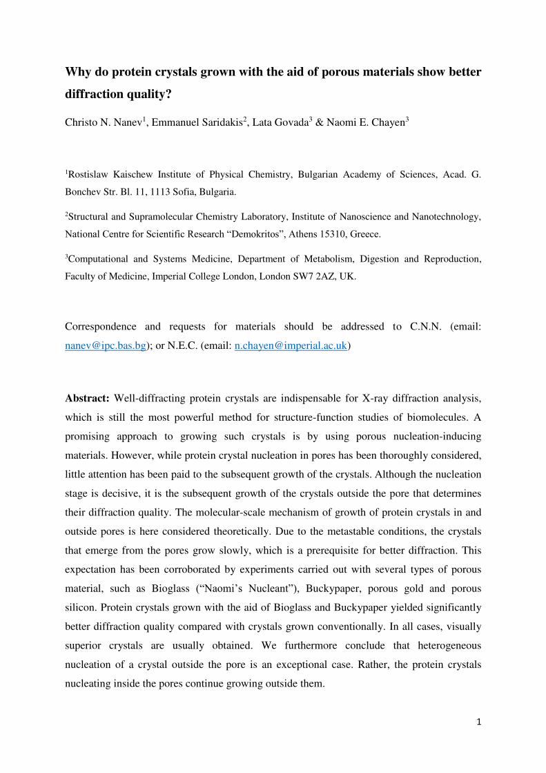
(i) Crystals of the C1 domain of the human cardiac myosin-binding protein-C (MyBP-C),
obtained on Buckypaper made from an aggregate of single-walled carbon nanotubes and
surfactant Triton X-100 (Fig. 4), diffracted to a maximum resolution of 1.6 Å (more
typically in the 2.0-2.2 Å range), which is far superior to the best crystals obtained using
standard techniques, which only diffracted to 3.0 Å [7]. The dominant pore size in that
Buckypaper was 9 nm. The crystals grew at metastable conditions in the trials with
porous material (10 mg/ml protein in 50 mM NaCl and 20 mM Tris ph 7.0, equilibrated
by vapour diffusion against a reservoir solution of 18% polyethylene glycol (PEG) of
mean MW 3350 and HEPES buffer, pH 7.3). The standardly obtained crystals were
obtained from 20% PEG reservoir solutions [7]. Importantly, in all cases, the crystals in
10
the drops containing nucleant were single, i.e., not in clusters that may have appeared if
repeated nucleation of novel 3D crystals outside the pore had occurred.
(ii) Crystals of InHr2 were obtained in the presence of Bioglass at metastable conditions
as well as at ‘borderline metastable’ conditions, i.e. conditions that gave visible crystals
overnight in the presence of Bioglass, but only after 6 days in the absence of porous
material (10 mg/ml protein equilibrated against a reservoir solution of 11% PEG of mean
MW 3350, 0.1 M imidazole at pH 7 and 75 mM MgCl2). The best of these crystals,
obtained from the latter conditions, diffracted to 3.2 Å, as compared to ca. 5 Å for
routinely obtained crystals at higher PEG concentrations.
(iii) Crystals of the cyclodextrin derivative per(6-guanidino-6-deoxy)-γCD (gguan) that were
obtained at metastable conditions in the presence of Bioglass (Fig. 5) diffracted to better
than 1.08 Å, whereas all X-rayed crystals routinely grown in standard, conventionally
optimized conditions, diffracted to 1.3 Å at best. This improvement in resolution enabled
the determination of this unusual structure (manuscript in preparation).
To be completely convinced of the porous material's ability to induce the formation of
crystalline nuclei, we always have used controls in each crystallization trial. While crystals
were observed in the samples containing porous nucleants, the controls set up at exactly the
same conditions but without addition of nucleant, were crystal-free. Undeniably, this is
completely convincing evidence that the porous material acted as a nucleant.
Figure 4. Crystals of MyBP-C growing on Buckypaper at metastable conditions
(Reprinted with permission from Asanithi et al. ACS Appl. Mat. Interf. 6, 1203-1210 (2009).
Copyright 2009 American Chemical Society)

11
Figure 5. Crystals of gguan growing on a grain of Bioglass (shown by red arrow) at
metastable conditions. Scale bar = 100 μm (First published in Khurshid et al. Nat. Prot. 9,
1621-1633 (2014)).
3. Discussion
Page and Sear [14] have found that, after the pore has been filled, the crystallization stops for
a relatively long period of time. The authors attributed this pause to the existence of a second
nucleation barrier, i.e., to the formation of an additional 3D crystal nucleus that is needed for
further crystal growth. Page and Sear state that “the nucleation often proceeds via two steps:
nucleation of pore filling, and nucleation out of the pore”. However, in our approach,
secondary crystal nucleation is not needed for the growth of the crystal outside the pore. In
fact, the protein crystal emerging from the pore orifice is a prolongation of the crystal grown
in the pore (Fig. 3), and hence, this crystal can hardly be under-critically sized. Importantly,
the surface of the crystal in the pore (which is a large part of the total crystal surface) is
protected from the destructive action of the water molecules, while the crystal itself is
strengthened due to the bonding to the pore walls. Thus, recalling that, according to
nucleation theory, for the same crystal volume a lower surface energy corresponds to a lower
supersaturation, we compare the crystal emerging from the pore with a heterogeneously
formed 3D crystal nucleus of the same volume; it is evident that the formation of a 3D crystal
nucleus requires higher supersaturation than the one that is sufficient for the protein crystal to
grow outside the pore orifice. Hence, no additional 3D nucleation is required. The protein
crystal emerging from the pore orifice (Fig. 3) simply grows outside it without impediment.

12
Besides, there is no guarantee that, if any, nucleation of a novel 3D crystal outside the
pore (see [14]) would be limited to a single crystal nucleus only - repeated formation of nuclei
cannot be excluded. Excess nucleation, leading to formation of sub-grains in the grown
crystal, would also be possible. In such cases, the diffraction quality of the grown protein
crystals would be deteriorated [15]; but this is not observed experimentally.
4. Conclusion
Growth of protein crystals in model pores of idealized shapes, rectangular and regular
hexagonal cross-sections, has been considered here (the reason being that they are readily
liable to be brought to quantitative accounts). Nevertheless, the unimpeded growth of the
crystal in pores is proven in an irrefutable manner. The use of model (idealized) pore shapes is
justified because, as already shown [13], the regularity of the pore shape is of no importance
for nucleation of protein crystals in pores; non-regularly shaped pore cross-sections yield
results that are very similar to those obtained with idealized pore shapes. Besides, only the
binding energies between the protein molecules in the crystal lattices are compared. The
reason is that the energy of adhesion of the protein molecules to the pore wall (which
additionally stabilizes the crystal) increases by the same value for every deposited mono-
molecular layer. Thus, the addition of the energy of adhesion of the protein molecules to the
pore wall would merely complicate the consideration but does not change the general
tendency towards crystal growth (with increasing crystal size, the adhesion energy plays a
lesser and lesser role).
Finally, the exact cause of the frequent poor diffraction quality of protein crystals
remained unclear till most recently. Koizumi et al. [15] have shown that it is not the
dislocations, but the local strain due to sub-grains that degrades the diffraction quality of
protein crystals. These authors demonstrate that the large stress exerted on the sub-grains of
protein crystals could significantly lower their resistance to radiation damage, and that this
strain can potentially be controlled by introducing grown-in dislocations in the crystal.
Therefore, we may advance the hypothesis that the misfit between the crystal lattice and the
supporting porous material can create grown-in dislocations, leading to a disappearance of
local strain in the sub-grains – and thus, improve the diffractivity of the protein crystals. In
fact, it has been observed [16] that some dislocations are grown from the seed crystals,
chemically cross-linked by glutaraldehyde. Thus, it is logical to assume that the supporting

13
porous material can be far more efficient in creating grown-in dislocations, because the misfit
between the crystal lattice and the supporting porous material is greater than in the former
case.
References
1. Chayen, N. E., Saridakis, E., El-Bahar, R. & Nemirovsky, Y. Porous silicon: an effective
nucleation-inducing material for protein crystallization. J. Mol. Biol. 312, 591–595 (2001).
2. Rong, L., Komatsu, H., Yoshizaki, I., Kadowaki, A. & Yoda, S. Protein crystallization by
using porous glass substrate. J. Synchrotron Radiat. 11, 27–29 (2004).
3. Chayen, N. E., Saridakis, E. & Sear, R. P. Experiment and theory for heterogeneous
nucleation of protein crystals in a porous medium. Proc. Natl. Acad. Sci. USA 103, 597–601
(2006).
4. Sugahara, M., Asada, Y., Morikawa, Y., Kageyama, Y. & Kunishima, N. Nucleant-
mediated protein crystallization with the application of microporous synthetic zeolites. Acta
Crystallogr. D64, 686–695 (2008).
5. Di Profio, G., Curcio, E., Ferraro, S., Stabile, C. & Drioli, E. Effect of supersaturation
control and heterogeneous nucleation on porous membrane surfaces in the crystallization of
L-glutamic acid polymorphs. Cryst. Growth Des. 9, 2179–2186 (2009).
6. Saridakis, E. & Chayen, N. E. Towards a ‘universal’ nucleant for protein crystallization.
Trends Biotechnol. 27, 99–106 (2009).
7. Asanithi, P. et al. Carbon-nanotube-based materials for protein crystallization. Appl. Mater.
Interfaces 1, 1203–1210 (2009).
8. Saridakis, E. et al. Protein crystallization facilitated by molecularly imprinted polymers.
Proc. Natl. Acad. Sci. USA 108, 11081–11086 (2011).
9. Kertis, F. et al. Heterogeneous nucleation of protein crystals using nanoporous gold
nucleants. J. Mater. Chem. 22, 21928-21934 (2012).
10. Saridakis, E. & Chayen, N. E. Imprinted polymers assisting protein crystallization. Trends
Biotechnol. 31, 515–520 (2013).

14
11. Khurshid, S., Saridakis, E., Govada, L. & Chayen, N. E. Porous nucleating agents for
protein crystallization. Nat. Protoc. 9, 1621–1633 (2014).
12. Nanev, C. N., Saridakis, E. & Chayen, N. E. Protein crystal nucleation in pores. Sci. Rep.
7, 35821; 10.1038/srep35821 (2017).
13. Nanev, C., Govada, L. & Chayen, N.E. Theoretical and experimental investigation of
protein crystal nucleation in pores and crevices. IUCrJ 8, 270-280 (2021).
14. Page, A. J. & Sear, R. P. Heterogeneous nucleation in and out of pores. Phys. Rev. Lett.
97, 065701 (2006).
15. Koizumi, H. et al. Control of strain in subgrains of protein crystals by the introduction of
grown-in dislocations. Acta Crystallogr. D77, 599-605 (2021).
16. Suzuki, R., Abe, M., Kojima K. & Tachibana, M. Identification of grown-in dislocations
in protein crystals by digital X-ray topography. J. Appl. Cryst. 54, 163-168 (2021).
Acknowledgements
This work was supported by COST Action CM1402-Crystallize, supported by COST
(European Cooperation in Science and Technology).
Author contributions
C.N.N. performed the theoretical investigation, L.G. and E.S. performed and analysed the
experiments, C.N.N. and N.E.C. led the research, C.N.N., E.S. and N.E.C. wrote the paper.
All authors reviewed the paper.
Competing interests
The author(s) declare no competing interests.


![Anthracene Fibers Grown in a Microstructured Optical Fiber ...€¦ · Many experimental techniques have been explored to grow and characterize anthracene crystals [21–24]. Large](https://img.pdfslide.us/doc/110x75/60052648d534fa307c57888b/anthracene-fibers-grown-in-a-microstructured-optical-fiber-many-experimental.jpg)