Embed Size (px)
Citation preview
1
Whole Skin Locomotion Inspired by Amoeboid
Motility Mechanisms: Mechanics of the Concentric Solid Tube Model
By Mark Edward Ingram
Thesis submitted to the faculty of the Virginia Polytechnic Institute and State University in partial fulfillment of the requirements for the degree of
Master of Science In
Mechanical Engineering
Dr. Dennis Hong, Committee Chair Dr. Charles Reinholtz
Dr. Robert Sturges
August 10, 2006 Blacksburg, Virginia
Keywords: Whole Skin Locomotion, Biomimetic, Robotics, Amoeba
Copyright 2006, Mark E. Ingram
ii
Whole Skin Locomotion Inspired by Amoeboid Motility Mechanisms: Mechanics of the Concentric Solid Tube Model
Mark E. Ingram
ABSTRACT
As the technology of robotics intelligence advances, and new application areas for mobile
robots increase, the need for alternative fundamental locomotion mechanisms for robots that
allow them to maneuver into complex unstructured terrain becomes critical. In this research we
present a novel locomotion mechanism for mobile robots inspired by the motility mechanism of
certain single celled organisms such as amoebae. Whole Skin Locomotion (WSL), as we call it,
works by way of an elongated toroid which turns itself inside out in a single continuous motion,
effectively generating the overall motion of the cytoplasmic streaming ectoplasmic tube in
amoebae.
This research presents the preliminary analytical study towards the design and
development of the novel WSL mechanism. In this thesis we first investigate how amoebas
move, then discuss how this motion can be replicated. By applying the biological theories of
amoeboid motility mechanisms, different actuation models for WSL are developed including the
Fluid Filled Toroid (FFT) and Concentric Solid Tube (CST) models. Then, a quasi-static force
analysis is performed for the CST model and parametric studies for design, including power
efficiency and force transition characteristics, are presented.
iii
Acknowledgments
I would like to acknowledge the following people for their help in my graduate work:
Dr. Dennis Hong, my advisor, for his tireless efforts, while simultaneously working on many
projects, including setting up RoMeLa (the Robotics and Mechanisms Laboratory). Working for
him has been a great experience.
Mrs. Hong, for her patience when I monopolize her husbands time.
My thesis committee, Dr. Charles Reinholtz and Dr. Robert Sturges for their time and useful
insights into the problem of Whole Skin Locomotion.
Mark Showalter for his work on the feasibility experiments, and all of my lab colleagues for their
assistance and sense of fun.
Dr. Harry Robertshaw and Dr. Michael Alley for hiring me a TA for multiple semesters, and
there guidance during that period of time.
Dr. Bob Williams of Ohio University for his mentorship during my undergraduate career, and
pointing me towards Virginia Tech.
And finally my parents for their constant support throughout my life, without which none of this
would be possible.
iv
Table of Contents
ABSTRACT .....................................................................................................................ii Acknowledgments ........................................................................................................iii Table of Contents..........................................................................................................iv Table of Figures .............................................................................................................v Chapter 1: Introduction .................................................................................................1 Chapter 2: Biologically Inspired Whole Skin Locomotion .........................................3 Chapter 3: Theories of Amoeboid Motility Mechanisms ............................................5
3.1 TAIL CONTRACTION ................................................................................................................................................... 5 3.2 FRONTAL-ZONE CONTRACTION................................................................................................................................. 6
Chapter 4: Models for the Whole Skin Locomotion Mechanism................................7 4.1 REAR CONTRACTILE RINGS WITH CST ..................................................................................................................... 8 4.2 FRONTAL EXPANSILE RINGS WITH CST.................................................................................................................... 8 4.3 WAVE CONTRACTILE/EXPANSILE RINGS WITH CST ................................................................................................ 9 4.4 REAR SKIN CONTRACTION WITH FFT ....................................................................................................................... 9 4.5 ACTUATION METHODS AND PACKAGING ................................................................................................................ 10
Chapter 5 ......................................................................................................................13 Feasibility Experiments...............................................................................................13
5.1 FEASIBILITY EXPERIMENT WITH PRE-TENSIONED ELASTIC SKIN .......................................................................... 13 5.2 REAR SKIN CONTRACTION EXPERIMENT USING TENSION CORDS......................................................................... 14
Chapter 6: Analysis of the CST Model .......................................................................16 NOMENCLATURE............................................................................................................................................................. 16 6.1 MECHANICS OF A SINGLE ACTUATION RING OVER A CST .................................................................................... 17
6.1.1 Region I............................................................................................................................................................. 18 6.1.2 Region II ........................................................................................................................................................... 20 6.1.3 Region III .......................................................................................................................................................... 24 6.1.4 Region IV .......................................................................................................................................................... 24
6.2 MECHANICAL ADVANTAGE AND EFFICIENCY FOR DIFFERENT CROSS-SECTION GEOMETRIES............................. 24 6.2.1 Round Cross-section, Region I ........................................................................................................................ 25 6.2.2 Straight Line Cross-section, Region I ............................................................................................................. 27 6.2.3 Composite Cross-section, Region I ................................................................................................................. 29 6.2.4 Region II ........................................................................................................................................................... 32 6.2.5 Region III and IV.............................................................................................................................................. 34
6.3 ANALYSIS AND SIMULATION FOR THE CST MODEL SYSTEM ................................................................................ 34 6.3.1 Displacement Constraints of the Actuation Rings for the CST Model System............................................. 34 6.3.2 Input Tension Required for the Actuation Rings for the CST Model System ............................................... 35
Chapter 7: Conclusions and Future Work .................................................................38 References ...................................................................................................................40
v
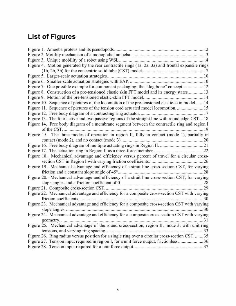
List of Figures Figure 1. Amoeba proteus and its pseudopods. ...........................................................................2 Figure 2. Motility mechanism of a monopodial amoeba. .............................................................3 Figure 3. Unique mobility of a robot using WSL........................................................................4 Figure 4. Motion generated by the rear contractile rings (1a, 2a, 3a) and frontal expansile rings
(1b, 2b, 3b) for the concentric solid tube (CST) model.....................................................7 Figure 5. Larger-scale actuation strategies................................................................................10 Figure 6. Smaller-scale actuation strategies with EAP. .............................................................10 Figure 7. One possible example for component packaging; the “dog bone” concept. ................12 Figure 8. Construction of a pre-tensioned elastic skin FFT model and its energy states.............13 Figure 9. Motion of the pre-tensioned elastic-skin FFT model..................................................14 Figure 10. Sequence of pictures of the locomotion of the pre-tensioned elastic-skin model.......14 Figure 11. Sequence of pictures of the tension cord actuated model locomotion. ......................15 Figure 12. Free body diagram of a contracting ring actuator. ....................................................17 Figure 13. The four active and two passive regions of the straight line with round edge CST. ..18 Figure 14. Free body diagram of a membrane segment between the contractile ring and region I
of the CST.....................................................................................................................19 Figure 15. The three modes of operation in region II, fully in contact (mode 1), partially in
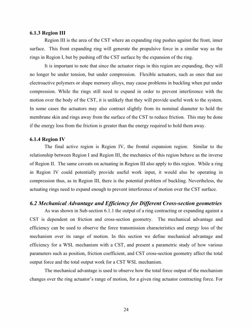
contact (mode 2), and no contact (mode 3). ...................................................................20 Figure 16. Free body diagram of multiple actuating rings in Region II. ....................................21 Figure 17. The actuation ring in Region II as a three-force member..........................................22 Figure 18. Mechanical advantage and efficiency versus percent of travel for a circular cross-
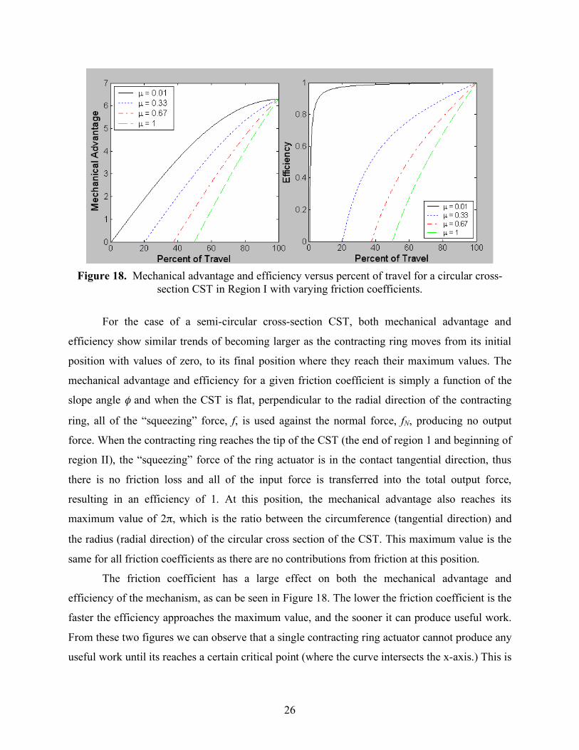
section CST in Region I with varying friction coefficients. ............................................26 Figure 19. Mechanical advantage and efficiency of a strait line cross-section CST, for varying
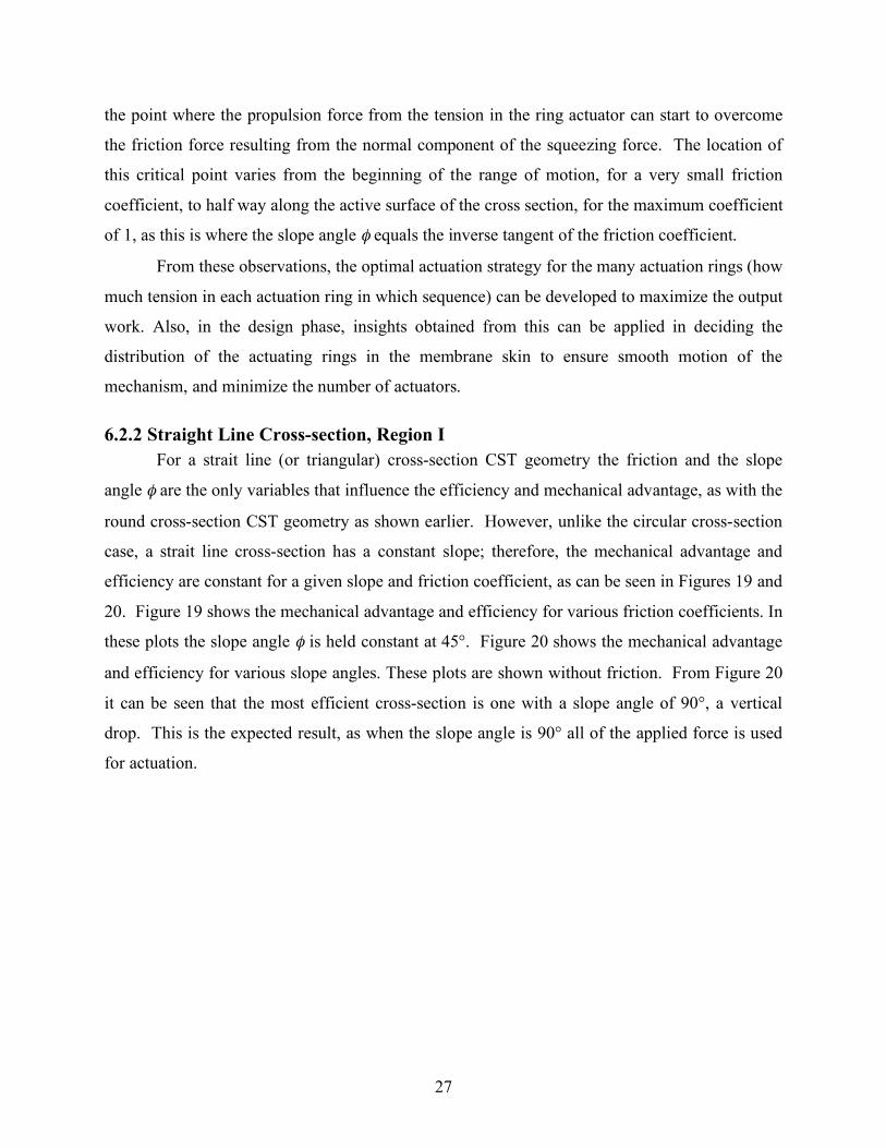
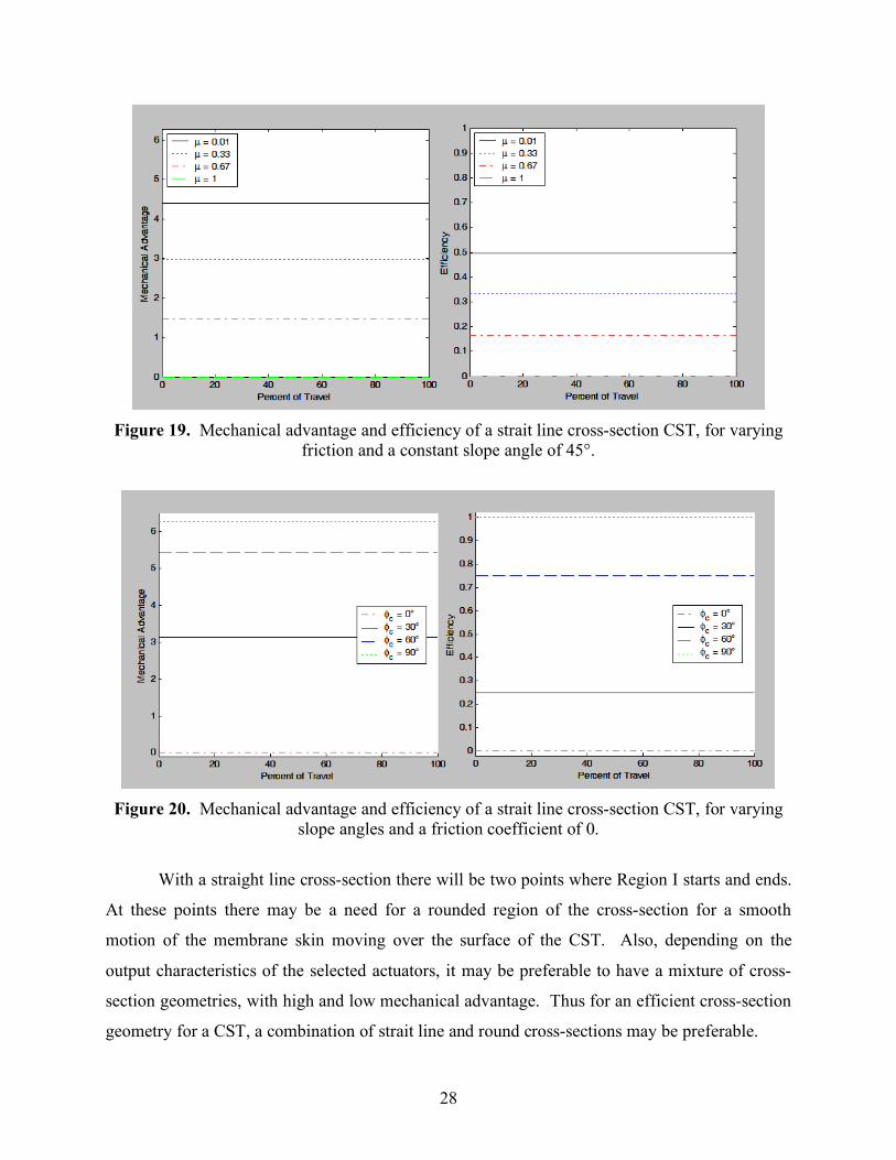
friction and a constant slope angle of 45°.......................................................................28 Figure 20. Mechanical advantage and efficiency of a strait line cross-section CST, for varying
slope angles and a friction coefficient of 0. ....................................................................28 Figure 21. Composite cross-section CST..................................................................................29 Figure 22. Mechanical advantage and efficiency for a composite cross-section CST with varying
friction coefficients........................................................................................................30 Figure 23. Mechanical advantage and efficiency for a composite cross-section CST with varying
slope angles. ..................................................................................................................30 Figure 24. Mechanical advantage and efficiency for a composite cross-section CST with varying
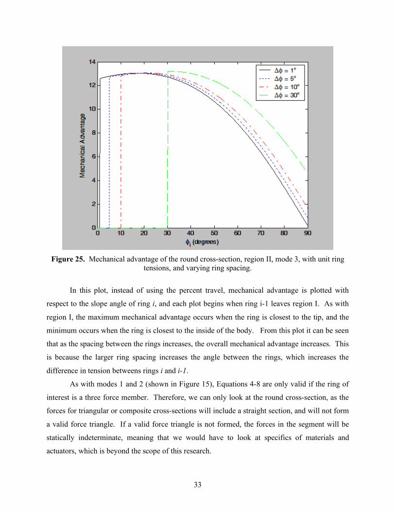
geometry. ......................................................................................................................31 Figure 25. Mechanical advantage of the round cross-section, region II, mode 3, with unit ring
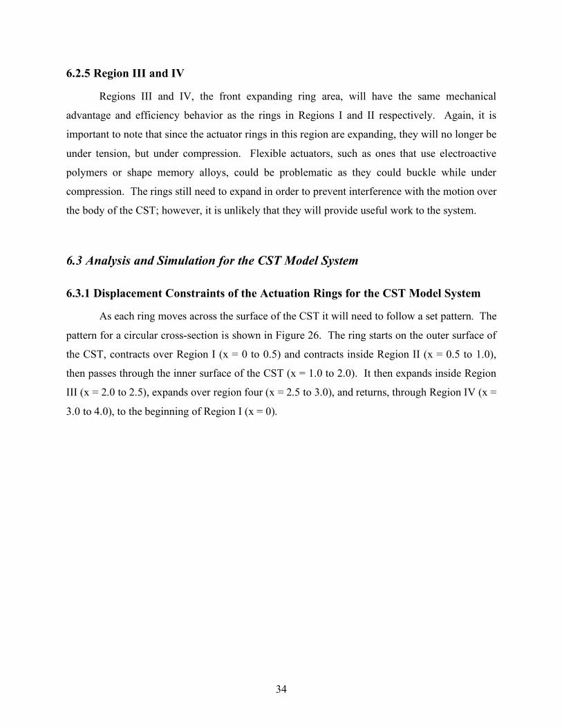
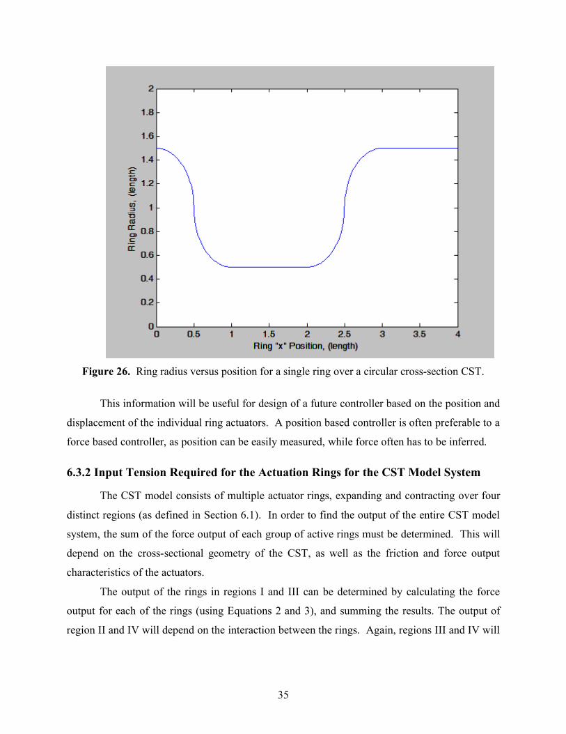
tensions, and varying ring spacing. ................................................................................33 Figure 26. Ring radius versus position for a single ring over a circular cross-section CST. .......35 Figure 27. Tension input required in region I, for a unit force output, frictionless. ....................36 Figure 28. Tension input required for a unit force output. .........................................................37
1
Chapter 1 Introduction
As the technology of robotics intelligence advances, and new application areas for mobile
robots increase, the need for alternative fundamental locomotion mechanisms for robots that can
enable them to maneuver into complex unstructured terrain becomes critical. Current methods of
ground vehicle locomotion are based on wheels, tracks or legs, and each of these methods has its
own strengths and weaknesses [1, 2, 3]. In order to move a robot into an area of complex terrain
a new method of locomotion is needed. For example, to be able to find people trapped in a
collapsed building, a robot would need to be able to move over, under and between rubble, and
maneuver itself into tight corners. Current methods of locomotion can do some part of this, but
they have only had limited success in achieving all of these capabilities [4, 5].
In this research we present a novel locomotion mechanism for mobile robots inspired by
the motility mechanism of certain single celled organisms such as amoebae (Figure 1). The
Whole Skin Locomotion (WSL) [6], as we call it, works by way of an elongated toroid which
turns itself inside out in a single continuous motion, effectively generating the overall motion of
the cytoplasmic streaming ectoplasmic tube in amoebae. The unique mobility of WSL makes this
the ideal locomotion method for search-and-rescue robots that need to traverse over or under
rubble [7, 8], or for medical applications such as robotic endoscopes where a robot needs to
maneuver itself into tight spaces [9, 10, 11]. The WSL is a new class of mechanism [12] that
generates an everting motion from the expanding and contracting motion of actuators that, if
successful, will also enable smart materials such as electroactive polymers to be used in ways not
possible before, opening the door for them to be used in new and exciting applications [13, 14,
15].
2
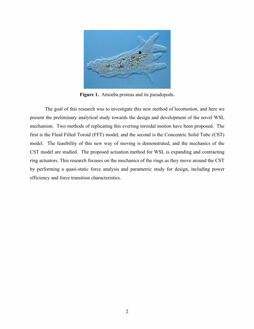
Figure 1. Amoeba proteus and its pseudopods.
The goal of this research was to investigate this new method of locomotion, and here we
present the preliminary analytical study towards the design and development of the novel WSL
mechanism. Two methods of replicating this everting toroidal motion have been proposed. The
first is the Fluid Filled Toroid (FFT) model, and the second is the Concentric Solid Tube (CST)
model. The feasibility of this new way of moving is demonstrated, and the mechanics of the
CST model are studied. The proposed actuation method for WSL is expanding and contracting
ring actuators. This research focuses on the mechanics of the rings as they move around the CST
by performing a quasi-static force analysis and parametric study for design, including power
efficiency and force transition characteristics.
3
Chapter 2
Biologically Inspired Whole Skin Locomotion
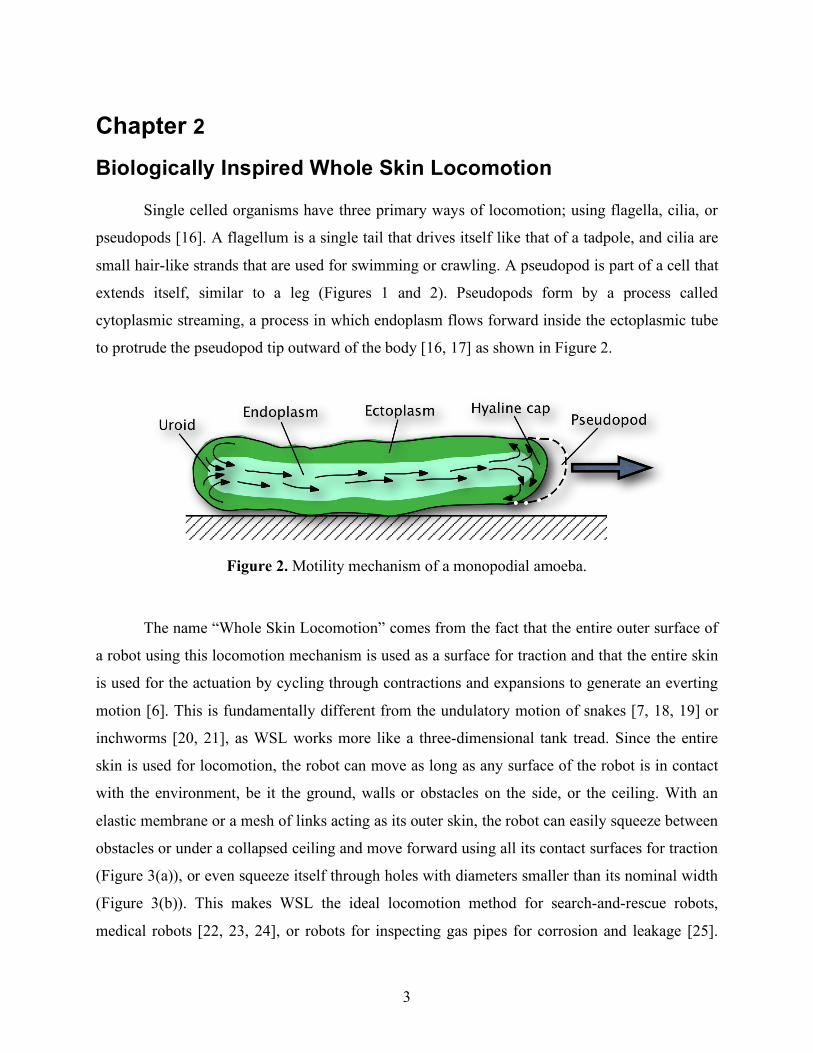
Single celled organisms have three primary ways of locomotion; using flagella, cilia, or
pseudopods [16]. A flagellum is a single tail that drives itself like that of a tadpole, and cilia are
small hair-like strands that are used for swimming or crawling. A pseudopod is part of a cell that
extends itself, similar to a leg (Figures 1 and 2). Pseudopods form by a process called
cytoplasmic streaming, a process in which endoplasm flows forward inside the ectoplasmic tube
to protrude the pseudopod tip outward of the body [16, 17] as shown in Figure 2.
Figure 2. Motility mechanism of a monopodial amoeba.
The name “Whole Skin Locomotion” comes from the fact that the entire outer surface of
a robot using this locomotion mechanism is used as a surface for traction and that the entire skin
is used for the actuation by cycling through contractions and expansions to generate an everting
motion [6]. This is fundamentally different from the undulatory motion of snakes [7, 18, 19] or
inchworms [20, 21], as WSL works more like a three-dimensional tank tread. Since the entire
skin is used for locomotion, the robot can move as long as any surface of the robot is in contact
with the environment, be it the ground, walls or obstacles on the side, or the ceiling. With an
elastic membrane or a mesh of links acting as its outer skin, the robot can easily squeeze between
obstacles or under a collapsed ceiling and move forward using all its contact surfaces for traction
(Figure 3(a)), or even squeeze itself through holes with diameters smaller than its nominal width
(Figure 3(b)). This makes WSL the ideal locomotion method for search-and-rescue robots,
medical robots [22, 23, 24], or robots for inspecting gas pipes for corrosion and leakage [25].
4
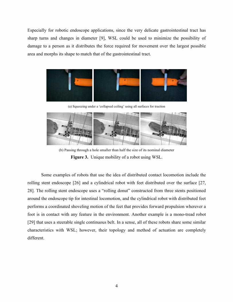
Especially for robotic endoscope applications, since the very delicate gastrointestinal tract has
sharp turns and changes in diameter [9], WSL could be used to minimize the possibility of
damage to a person as it distributes the force required for movement over the largest possible
area and morphs its shape to match that of the gastrointestinal tract.
(a) Squeezing under a ‘collapsed ceiling’ using all surfaces for traction
(b) Passing through a hole smaller than half the size of its nominal diameter
Figure 3. Unique mobility of a robot using WSL.
Some examples of robots that use the idea of distributed contact locomotion include the
rolling stent endoscope [26] and a cylindrical robot with feet distributed over the surface [27,
28]. The rolling stent endoscope uses a “rolling donut” constructed from three stents positioned
around the endoscope tip for intestinal locomotion, and the cylindrical robot with distributed feet
performs a coordinated shoveling motion of the feet that provides forward propulsion wherever a
foot is in contact with any feature in the environment. Another example is a mono-tread robot
[29] that uses a steerable single continuous belt. In a sense, all of these robots share some similar
characteristics with WSL; however, their topology and method of actuation are completely
different.
5
Chapter 3
Theories of Amoeboid Motility Mechanisms
Among the many theories of amoeboid motility mechanisms proposed by biologists [16,
17, 30], we will be applying two theories we consider the most useful to adapt and implement for
the WSL actuation models. These are the tail contraction model and the frontal-zone contraction
model.
In both models, the motion of the body is caused by the process of cytoplasmic streaming
(Figure 2). Cytoplasm is made up of gel-like ectoplasm and liquid endoplasm. The endoplasm
flows forward inside the ectoplasmic tube, which acts as the outer skin. When the endoplasm
reaches the front, it turns into the gel-like ectoplasm forming the pseudopodial tip in a region
called the hyaline cap. The pseudopodial tip in turn forms an extension of the ectoplasmic tube,
moving the organism forward. As the amoeba advances, the ectoplasmic tube turns into the
liquid endoplasm at the rear, or uroid of the cell, and the process continues [16, 17]. The net
effect of this ectoplasm-endoplasm transformation is the forward motion of the amoeba.
Most researchers in the field agree that the motor for the motion of the amoeba is
actomyosin based. Actomyosin is a protein complex in muscle fibers composed of myosin and
actin. It shortens when stimulated and causes muscle contractions in biological systems [16, 17,
31]. Exactly how the actomyosin based cytoplasmic streaming happens is still debated, and many
theories exist; however, the tail contraction model and the frontal-zone contraction model are the
two theories we apply to the WSL mechanism model.
3.1 Tail Contraction The tail contraction model, first put forward by Ecker [32, 33], is based on the observable
contraction of the rear of the cell. While the amoeba is moving, the membrane around the uroid,
or tail, folds up because the ectoplasm immediately under it is turning into endoplasm. The idea
is that as the tail contracts, it causes a small positive pressure within the cytoplasm which would
force more fluid endoplasm forward along the line of least resistance. This theory was supported
by basic observations of a moving amoeba, and in experiments where particles implanted in the
cytoplasm come closer together in the uroid, indicating contraction of the cytoplasm [34]. The
6
pressure gradient caused by the contraction can be measured by having an amoeba crawl through
a hole between two chambers and measuring the pressure difference [16].
3.2 Frontal-Zone Contraction The frontal-zone contraction model proposes to explain the mechanism by the assembly
process of endoplasm into gel-like ectoplasm at the advancing tip of the pseudopod,
accompanied by contraction, pulling the endoplasm forward and pushing the pseudopod tip
outward. This theory was proposed after an experiment in 1960 which could not be explained by
the tail contraction model [30]. In this experiment, the membrane of an amoeba is broken by
taking an amoeba in a glass capillary, and then breaking the glass capillary. The cytoplasm was
able to flow in multiple directions even without the contracting uroid suggesting that the tail
contraction model is not the only mechanism for cytoplasmic streaming [31, 35]. Other
experiments followed further showing that the pressure gradient was not the sole driving force
behind amoeboid locomotion [30, 36, 37]. However, there is still no direct evidence showing
either theory to be correct or incorrect, and thus the debate on the amoeboid motility mechanism
continues.
7
Chapter 4
Models for the Whole Skin Locomotion Mechanism
Inspired by the cytoplasmic streaming motility mechanism of monopodial single cell
organisms like the amoeba, we propose the WSL mechanism as an alternative locomotion
strategy for mobile robots. Directly imitating the tail contraction model or the frontal-zone
contraction model of the cytoplasmic streaming process is very difficult to do, if not impossible,
since it would be very challenging to implement something similar to the endoplasm-ectoplasm
transformation in macro scale (using electrorheological or magnetorheological fluids maybe
some possible ideas for implementing this). Thus, instead of using the process of liquid-to-gel
cytoplasm transformation, we plan to implement WSL using a flexible membrane skin (or a
mesh of links) in the shape of a long torus. The skin of this elongated torus can then rotate in the
longitudinal direction, turning itself inside out in a single continuous everting motion, effectively
generating the overall motion of the cytoplasmic streaming ectoplasmic tube in amoebae (Figure
4).
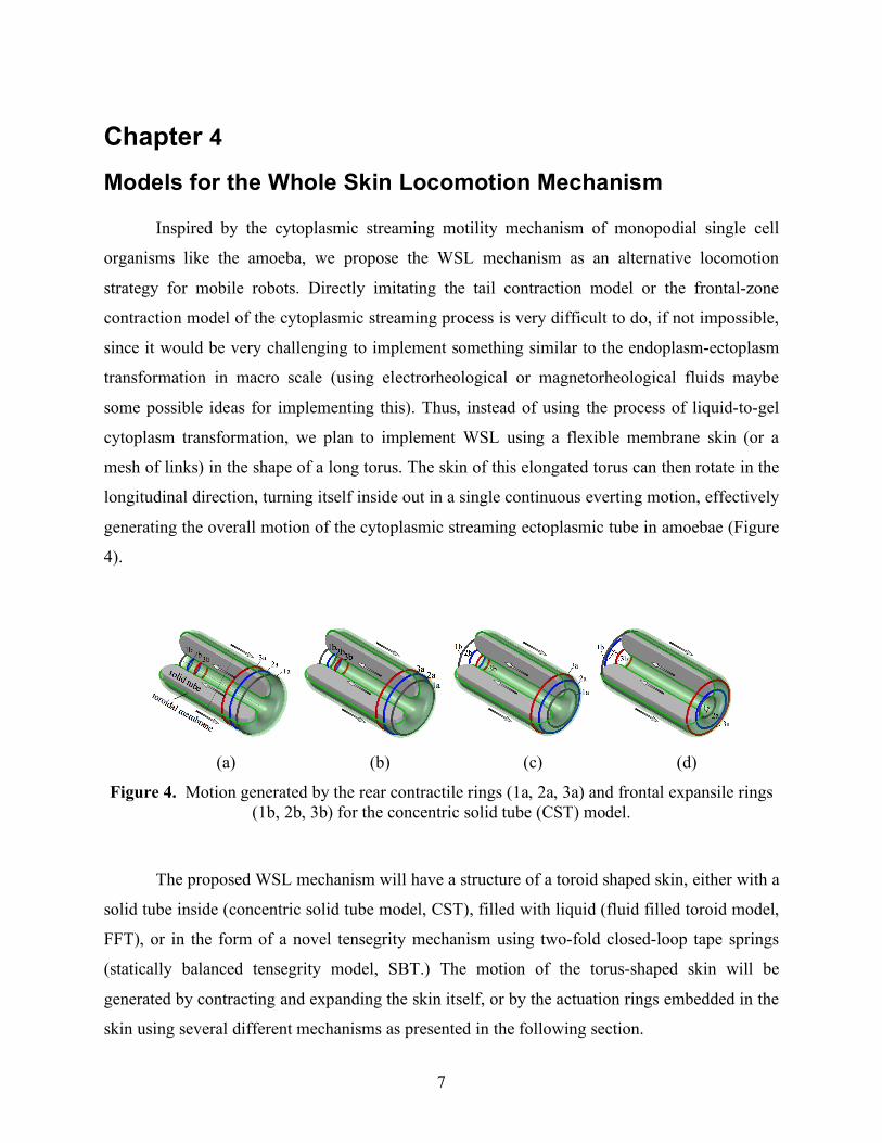
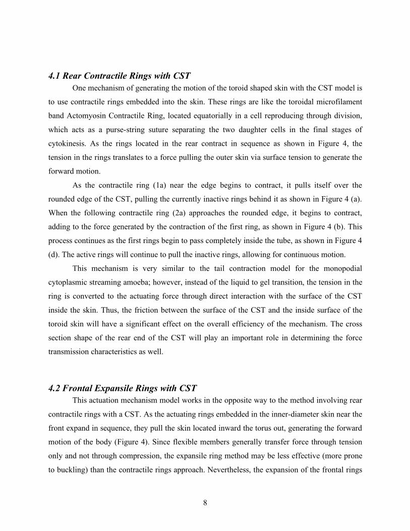
(a) (b) (c) (d)
Figure 4. Motion generated by the rear contractile rings (1a, 2a, 3a) and frontal expansile rings (1b, 2b, 3b) for the concentric solid tube (CST) model.
The proposed WSL mechanism will have a structure of a toroid shaped skin, either with a
solid tube inside (concentric solid tube model, CST), filled with liquid (fluid filled toroid model,
FFT), or in the form of a novel tensegrity mechanism using two-fold closed-loop tape springs
(statically balanced tensegrity model, SBT.) The motion of the torus-shaped skin will be
generated by contracting and expanding the skin itself, or by the actuation rings embedded in the
skin using several different mechanisms as presented in the following section.
8
4.1 Rear Contractile Rings with CST One mechanism of generating the motion of the toroid shaped skin with the CST model is
to use contractile rings embedded into the skin. These rings are like the toroidal microfilament
band Actomyosin Contractile Ring, located equatorially in a cell reproducing through division,
which acts as a purse-string suture separating the two daughter cells in the final stages of
cytokinesis. As the rings located in the rear contract in sequence as shown in Figure 4, the
tension in the rings translates to a force pulling the outer skin via surface tension to generate the
forward motion.
As the contractile ring (1a) near the edge begins to contract, it pulls itself over the
rounded edge of the CST, pulling the currently inactive rings behind it as shown in Figure 4 (a).
When the following contractile ring (2a) approaches the rounded edge, it begins to contract,
adding to the force generated by the contraction of the first ring, as shown in Figure 4 (b). This
process continues as the first rings begin to pass completely inside the tube, as shown in Figure 4
(d). The active rings will continue to pull the inactive rings, allowing for continuous motion.
This mechanism is very similar to the tail contraction model for the monopodial
cytoplasmic streaming amoeba; however, instead of the liquid to gel transition, the tension in the
ring is converted to the actuating force through direct interaction with the surface of the CST
inside the skin. Thus, the friction between the surface of the CST and the inside surface of the
toroid skin will have a significant effect on the overall efficiency of the mechanism. The cross
section shape of the rear end of the CST will play an important role in determining the force
transmission characteristics as well.
4.2 Frontal Expansile Rings with CST This actuation mechanism model works in the opposite way to the method involving rear
contractile rings with a CST. As the actuating rings embedded in the inner-diameter skin near the
front expand in sequence, they pull the skin located inward the torus out, generating the forward
motion of the body (Figure 4). Since flexible members generally transfer force through tension
only and not through compression, the expansile ring method may be less effective (more prone
to buckling) than the contractile rings approach. Nevertheless, the expansion of the frontal rings
9
is still necessary to not constrain the overall motion of the skin, even if they are not used for
generating the force for achieving motion. Note that the frontal expansile ring mechanism is not
exactly analogous to the frontal-zone contraction theory for the monopodial cytoplasmic
streaming amoeba.
4.3 Wave Contractile/Expansile Rings with CST One potential problem of the two proposed methods used with the CST model presented
above is that only a small portion of the actuators are being used at a given time. To increase the
usage of the actuators and the overall effectiveness of the mechanism, both of these approaches
can be utilized not only in the front and rear of the body, but all over the surface of the CST by
forming the tube in a wave shape on the inner and outer surfaces, such as a sinusoidal or a saw
tooth wave. This would allow all of the actuating rings to drive the skin simultaneously, taking
advantage of the whole surface of the robot and improving the overall effectiveness of the
mechanism.
4.4 Rear Skin Contraction with FFT Instead of using the CST inside the toroidal skin, it could be filled with liquid, which
would provide certain benefits. First, this will eliminate the friction caused at the interface
between the skin and the solid tube, and second, it will allow the necessary compliance for the
robot to squeeze between obstacles and morph into different length and diameter shapes. This is
similar to a common child’s toy that is often referred to as a “water worm” or a “water wiggler.”
With liquid filling the inside of the toroidal skin, the mechanism of generating the skin motion
changes significantly from the proposed models using a CST. The actuating rings on the outside
would compress the rear end, which would cause the liquid to flow forward, pushing out the
inner skin in the front forward, generating the motion of the skin. This would be like squeezing
toothpaste out of a tube, with the tube continuously reforming at the front. This approach is the
closest to the tail contraction theory for the monopodial cytoplasmic streaming amoeba.
10
4.5 Actuation Methods and Packaging The WSL mechanism is a new class of mechanism that converts contracting and
expanding motion of a ring to a toroidal everting motion. Thus, it does not require conventional
actuators such as electric motors or linear actuators. To actuate the contracting and expanding
rings to generate the desired motion for the WSL mechanism, two different methods are
proposed, one method for the larger-scale implementation (Figure 5) and the other for the
smaller-scale implementation (Figure 6).
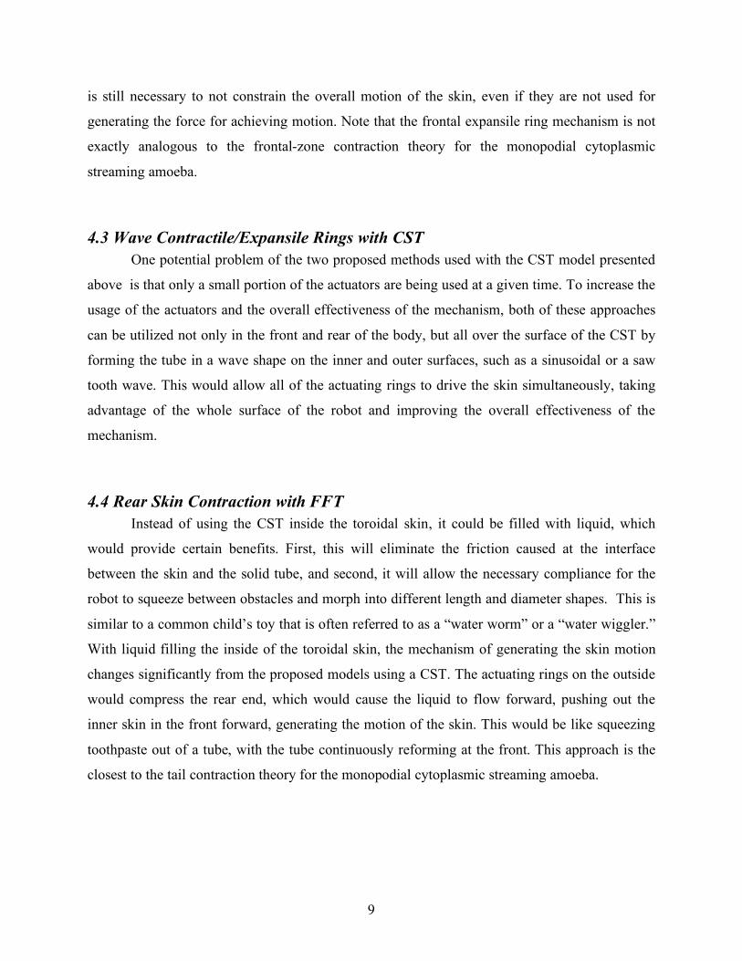
(a) WSL with pressurized expandable hoses (b) Expanded (c) Contracted
Figure 5. Larger-scale actuation strategies.
The larger-scale method consists of rings of accordion-type hose that are expanded and
contracted using pressurized fluid, such as compressed air, as shown in Figures 5 (b) and (c). The
benefit of this strategy is that a large displacement (strain) can be obtained easily and the
actuation force can be made large since it simply depends on the pressure of the fluid in the
expanding hoses. These expanding rings can be embedded into the skin of the robot as channels,
making it a robust approach for generating the rotating toroidal motion.
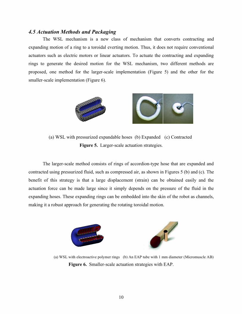
(a) WSL with electroactive polymer rings (b) An EAP tube with 1 mm diameter (Micromuscle AB)
Figure 6. Smaller-scale actuation strategies with EAP.
11
The smaller-scale method being considered uses rings of electroactive polymer (EAP)
strips around the toroid to drive the motion (Figure 6). EAPs are active polymeric materials in
which a stress and strain can be generated by the application of voltage and current (Figure 6(b))
[39]. Active materials may be the ideal actuators for WSL, since the strain they are able to
produce is the type of displacement needed for WSL. Though promising, the general problem of
this approach is the lack of force generated by these active materials [40]. Thus, EAPs are only
considered for small-scale implementations. Among the many different types of EAPs,
ionomeric polymers in particular will be studied for this application. Ionomeric polymers operate
through the exchange of electrons and ions between a polymer and an electrolytic solution driven
by an electric field between them. Thus ionomeric polymers must remain wet for the motion to
take place, which is normally a problem for most applications [41]. However, this is not a
concern for the FFT model as it needs to be filled with some kind of fluid.
The unique topology and nature of the everting motion of WSL presents practical
challenges in packaging such as sensor integration, power delivery to the actuators and so forth.
Since the entire outer skin rotates, attaching sensors to it becomes a problem. Moreover,
packaging the power source and electronic components inside the robot becomes challenging.
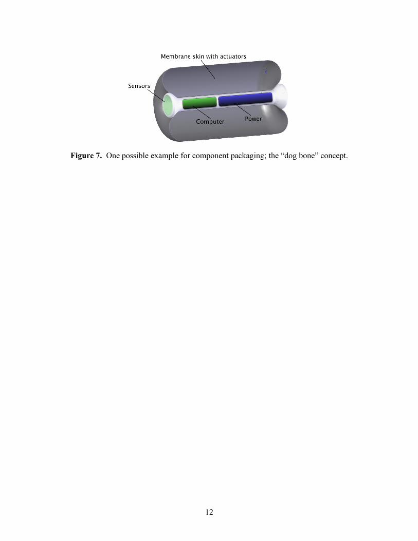
We have several ideas for addressing these issues, one of them shown in Figure 7. The cylinder
located at the center of the robot with caps at both ends serves as the body for the robot which
the skin everts around it. This cylinder, the “dog bone” as we call it, may house the power source
and supporting components. The tapered end caps prevent the toroid skin from sliding off the
cylinder and also provide the ideal location for mounting sensors such as cameras or others
depending on the application. However, this work focuses on the study of actuation mechanisms
for WSL. We hope this new paradigm in locomotion will inspire others to produce novel
component technologies such as chemical power sources, membrane embedded micro-channels
to connect the expanding and contracting hose actuator pairs, micro pumps, and other
components which may be applicable to future implementations of robots that use WSL.
12
Figure 7. One possible example for component packaging; the “dog bone” concept.
13
Chapter 5
Feasibility Experiments
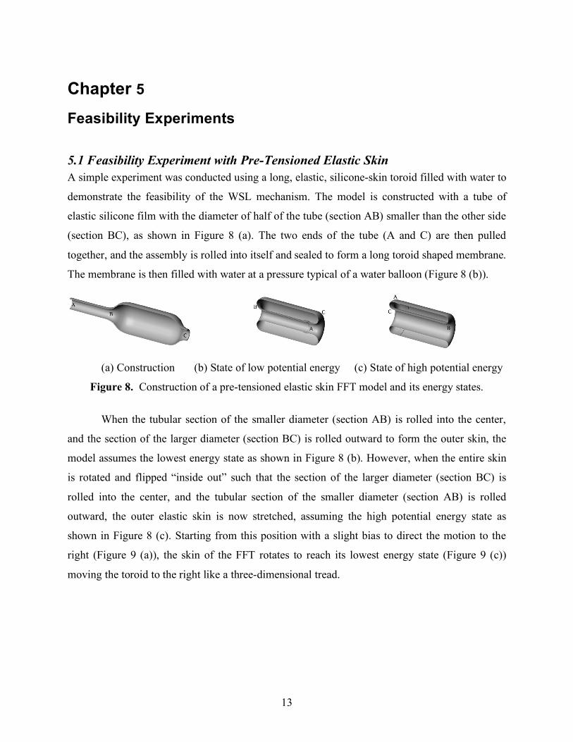
5.1 Feasibility Experiment with Pre-Tensioned Elastic Skin A simple experiment was conducted using a long, elastic, silicone-skin toroid filled with water to
demonstrate the feasibility of the WSL mechanism. The model is constructed with a tube of
elastic silicone film with the diameter of half of the tube (section AB) smaller than the other side
(section BC), as shown in Figure 8 (a). The two ends of the tube (A and C) are then pulled
together, and the assembly is rolled into itself and sealed to form a long toroid shaped membrane.
The membrane is then filled with water at a pressure typical of a water balloon (Figure 8 (b)).
(a) Construction (b) State of low potential energy (c) State of high potential energy
Figure 8. Construction of a pre-tensioned elastic skin FFT model and its energy states.
When the tubular section of the smaller diameter (section AB) is rolled into the center,
and the section of the larger diameter (section BC) is rolled outward to form the outer skin, the
model assumes the lowest energy state as shown in Figure 8 (b). However, when the entire skin
is rotated and flipped “inside out” such that the section of the larger diameter (section BC) is
rolled into the center, and the tubular section of the smaller diameter (section AB) is rolled
outward, the outer elastic skin is now stretched, assuming the high potential energy state as
shown in Figure 8 (c). Starting from this position with a slight bias to direct the motion to the
right (Figure 9 (a)), the skin of the FFT rotates to reach its lowest energy state (Figure 9 (c))
moving the toroid to the right like a three-dimensional tread.
14
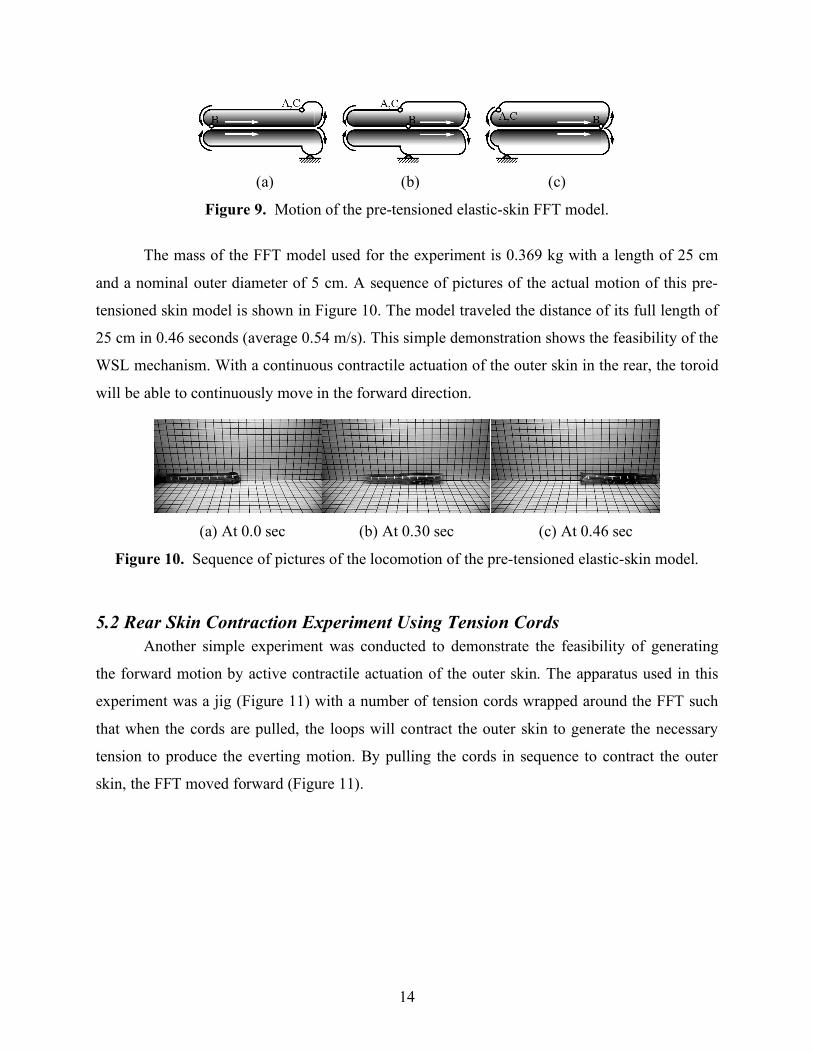
(a) (b) (c)
Figure 9. Motion of the pre-tensioned elastic-skin FFT model.
The mass of the FFT model used for the experiment is 0.369 kg with a length of 25 cm
and a nominal outer diameter of 5 cm. A sequence of pictures of the actual motion of this pre-
tensioned skin model is shown in Figure 10. The model traveled the distance of its full length of
25 cm in 0.46 seconds (average 0.54 m/s). This simple demonstration shows the feasibility of the
WSL mechanism. With a continuous contractile actuation of the outer skin in the rear, the toroid
will be able to continuously move in the forward direction.
(a) At 0.0 sec (b) At 0.30 sec (c) At 0.46 sec
Figure 10. Sequence of pictures of the locomotion of the pre-tensioned elastic-skin model.
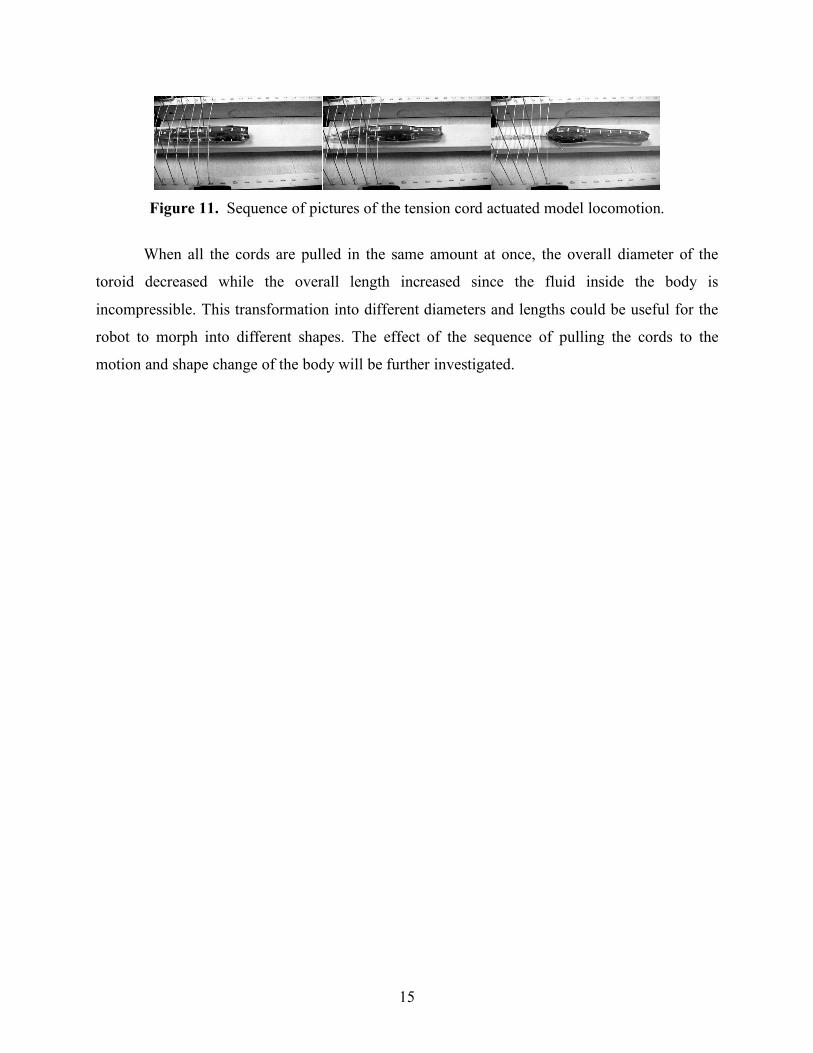
5.2 Rear Skin Contraction Experiment Using Tension Cords Another simple experiment was conducted to demonstrate the feasibility of generating
the forward motion by active contractile actuation of the outer skin. The apparatus used in this
experiment was a jig (Figure 11) with a number of tension cords wrapped around the FFT such
that when the cords are pulled, the loops will contract the outer skin to generate the necessary
tension to produce the everting motion. By pulling the cords in sequence to contract the outer
skin, the FFT moved forward (Figure 11).
15
Figure 11. Sequence of pictures of the tension cord actuated model locomotion.
When all the cords are pulled in the same amount at once, the overall diameter of the
toroid decreased while the overall length increased since the fluid inside the body is
incompressible. This transformation into different diameters and lengths could be useful for the
robot to morph into different shapes. The effect of the sequence of pulling the cords to the
motion and shape change of the body will be further investigated.
16
Chapter 6
Analysis of the CST Model
Nomenclature
η Efficiency of a single actuating ring over a CST
µ The coefficient of Coulomb friction between the contracting ring and the CST surface
φ The slope angle of the CST surface in the longitudinal direction
c The circumference of a contracting ring actuator [length]
f Distributed force along the inside of a contracting ring in the radial direction (the
“squeezing” force of an actuator ring on the CST surface) [force/length]
ff Distributed friction force in the longitudinal direction between the contracting ring and
the CST surface [force/length]
fN Distributed normal force on the surface of a CST in the radial direction due to a
contracting ring actuator [force/length]
fR Distributed output “propulsion” force in the longitudinal direction of a single contracting
ring actuator [force/length]
fT,l,m Distributed tension force on a skin segment between two actuating rings, acting from ring
l to ring m [force/length]
F The total propulsion output force generated by a contracting actuation ring(s) [force]
MA Mechanical advantage, defined as the output force divided by the input force
R The radius of a contracting ring actuator [length]
s Position of an actuation ring represented as the distance from a fixed reference on the
CST, along its travel path on the CST surface in the longitudinal direction [length]
TR Tension in a contracting ring actuator [force]
n The nominal number of actuating rings per unit length in the longitudinal direction
assuming equal distribution
N The number of active contracting actuator rings
x Horizontal position coordinate of the actuator ring
y Vertical position coordinate of the actuator ring
17
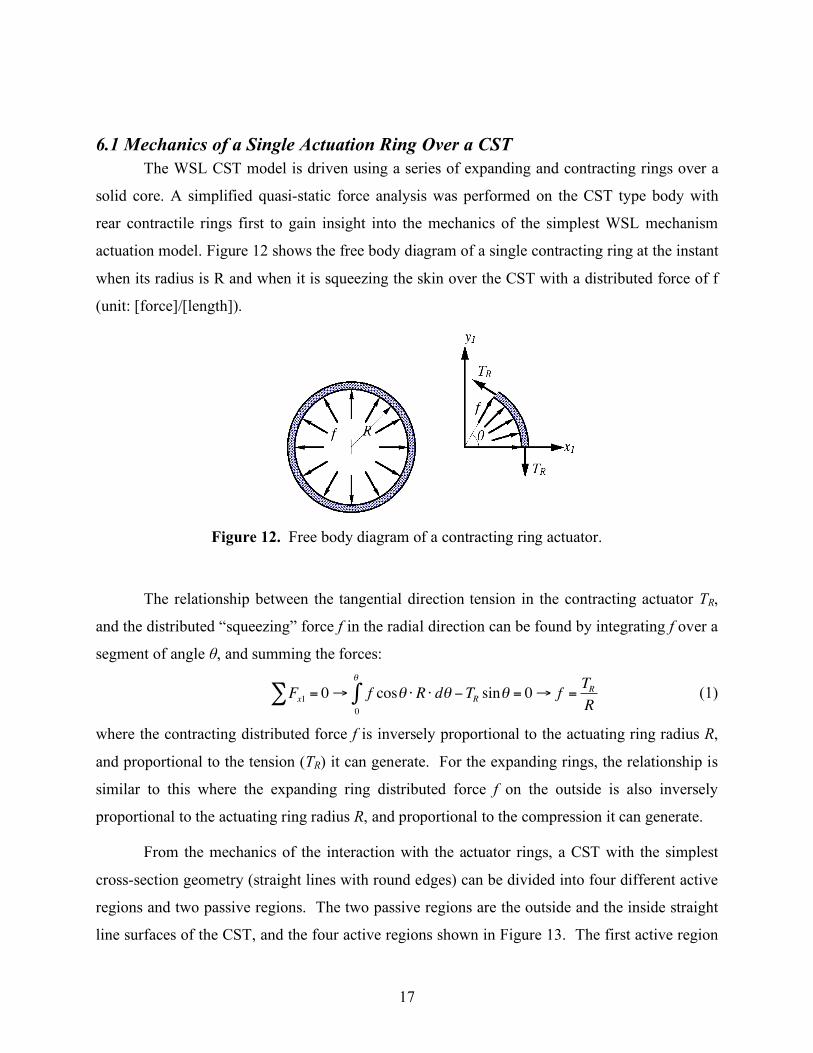
6.1 Mechanics of a Single Actuation Ring Over a CST The WSL CST model is driven using a series of expanding and contracting rings over a
solid core. A simplified quasi-static force analysis was performed on the CST type body with
rear contractile rings first to gain insight into the mechanics of the simplest WSL mechanism
actuation model. Figure 12 shows the free body diagram of a single contracting ring at the instant
when its radius is R and when it is squeezing the skin over the CST with a distributed force of f
(unit: [force]/[length]).
Figure 12. Free body diagram of a contracting ring actuator.
The relationship between the tangential direction tension in the contracting actuator TR,
and the distributed “squeezing” force f in the radial direction can be found by integrating f over a
segment of angle θ, and summing the forces:
!
Fx1 = 0" # f cos$ % R % d$0
$
& 'TR sin$ = 0# f =TR
R (1)
where the contracting distributed force f is inversely proportional to the actuating ring radius R,
and proportional to the tension (TR) it can generate. For the expanding rings, the relationship is
similar to this where the expanding ring distributed force f on the outside is also inversely
proportional to the actuating ring radius R, and proportional to the compression it can generate.
From the mechanics of the interaction with the actuator rings, a CST with the simplest
cross-section geometry (straight lines with round edges) can be divided into four different active
regions and two passive regions. The two passive regions are the outside and the inside straight
line surfaces of the CST, and the four active regions shown in Figure 13. The first active region
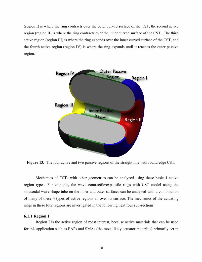
18
(region I) is where the ring contracts over the outer curved surface of the CST, the second active
region (region II) is where the ring contracts over the inner curved surface of the CST. The third
active region (region III) is where the ring expands over the inner curved surface of the CST, and
the fourth active region (region IV) is where the ring expands until it reaches the outer passive
region.
Figure 13. The four active and two passive regions of the straight line with round edge CST.
Mechanics of CSTs with other geometries can be analyzed using these basic 4 active
region types. For example, the wave contractile/expansile rings with CST model using the
sinusoidal wave shape tube on the inner and outer surfaces can be analyzed with a combination
of many of these 4 types of active regions all over its surface. The mechanics of the actuating
rings in these four regions are investigated in the following next four sub-sections.
6.1.1 Region I Region I is the active region of most interest, because active materials that can be used
for this application such as EAPs and SMAs (the most likely actuator materials) primarily act in
19
tension. Also, as will be explored in the following sub sections, actuation in other active regions
(regions III and IV) by expansion of the actuator rings can experience problems with buckling.
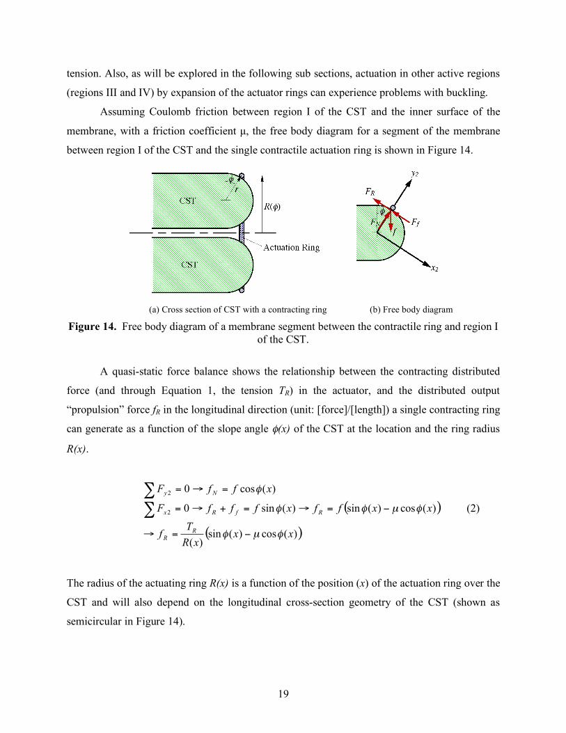
Assuming Coulomb friction between region I of the CST and the inner surface of the
membrane, with a friction coefficient µ, the free body diagram for a segment of the membrane
between region I of the CST and the single contractile actuation ring is shown in Figure 14.
(a) Cross section of CST with a contracting ring (b) Free body diagram
Figure 14. Free body diagram of a membrane segment between the contractile ring and region I of the CST.
A quasi-static force balance shows the relationship between the contracting distributed
force (and through Equation 1, the tension TR) in the actuator, and the distributed output
“propulsion” force fR in the longitudinal direction (unit: [force]/[length]) a single contracting ring
can generate as a function of the slope angle φ(x) of the CST at the location and the ring radius
R(x).
( )
( ))(cos)(sin)(
)(cos)(sin)(sin0
)(cos0
2
2
xxxR
Tf
xxffxfffF
xffF
RR
RfRx
Ny
!µ!
!µ!!
!
"=#
"=#=+#=
=#=
$$
(2)
The radius of the actuating ring R(x) is a function of the position (x) of the actuation ring over the
CST and will also depend on the longitudinal cross-section geometry of the CST (shown as
semicircular in Figure 14).
20
The total output “propulsion” force of a single contracting ring over a CST is found by
multiplying the longitudinal output force per unit tangential length (fR) by the circumferential
length over which it acts (2πR(x)). This leads to the following input-output relationship:
( ))(cos)(sin2)( xxTxFR
!µ!" #= (3)
From this it can be seen that the total output “propulsion” force F of a single contracting ring
over a CST is only dependent on the friction coefficient and the slope angle φ(x) of the CST at
the location of the actuating ring, thus the friction and end shape of the CST will have a great
effect on the force transmission characteristics and the efficiency of the mechanism, as will be
shown in the following sections.
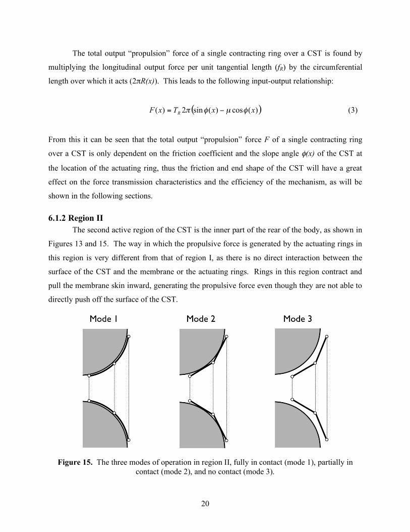
6.1.2 Region II The second active region of the CST is the inner part of the rear of the body, as shown in
Figures 13 and 15. The way in which the propulsive force is generated by the actuating rings in
this region is very different from that of region I, as there is no direct interaction between the
surface of the CST and the membrane or the actuating rings. Rings in this region contract and
pull the membrane skin inward, generating the propulsive force even though they are not able to
directly push off the surface of the CST.
Figure 15. The three modes of operation in region II, fully in contact (mode 1), partially in
contact (mode 2), and no contact (mode 3).
21
There are three modes of operation in this region, depending on the contact state of the
rings and membrane skin to the CST surface as shown in Figure 15. The rings and the skin can
both be fully in contact with the surface of the CST (Figure 15-a), the rings can be out of contact
with the body while the connecting skin segments are in contact with the surface of the CST
(Figure 15-b), or both the rings and connecting skin segments can be out of contact with the
surface of the CST (Figure 15-c), depending on the state of actuation. In this last mode of
operation there will be no friction between the membrane skin and the surface of the CST thus it
may be the most desirable way of operating.
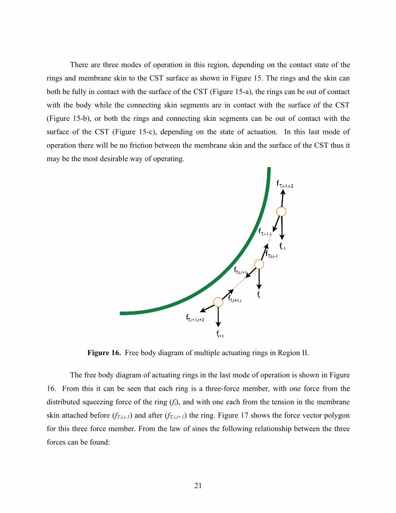
Figure 16. Free body diagram of multiple actuating rings in Region II.
The free body diagram of actuating rings in the last mode of operation is shown in Figure
16. From this it can be seen that each ring is a three-force member, with one force from the
distributed squeezing force of the ring (fi), and with one each from the tension in the membrane
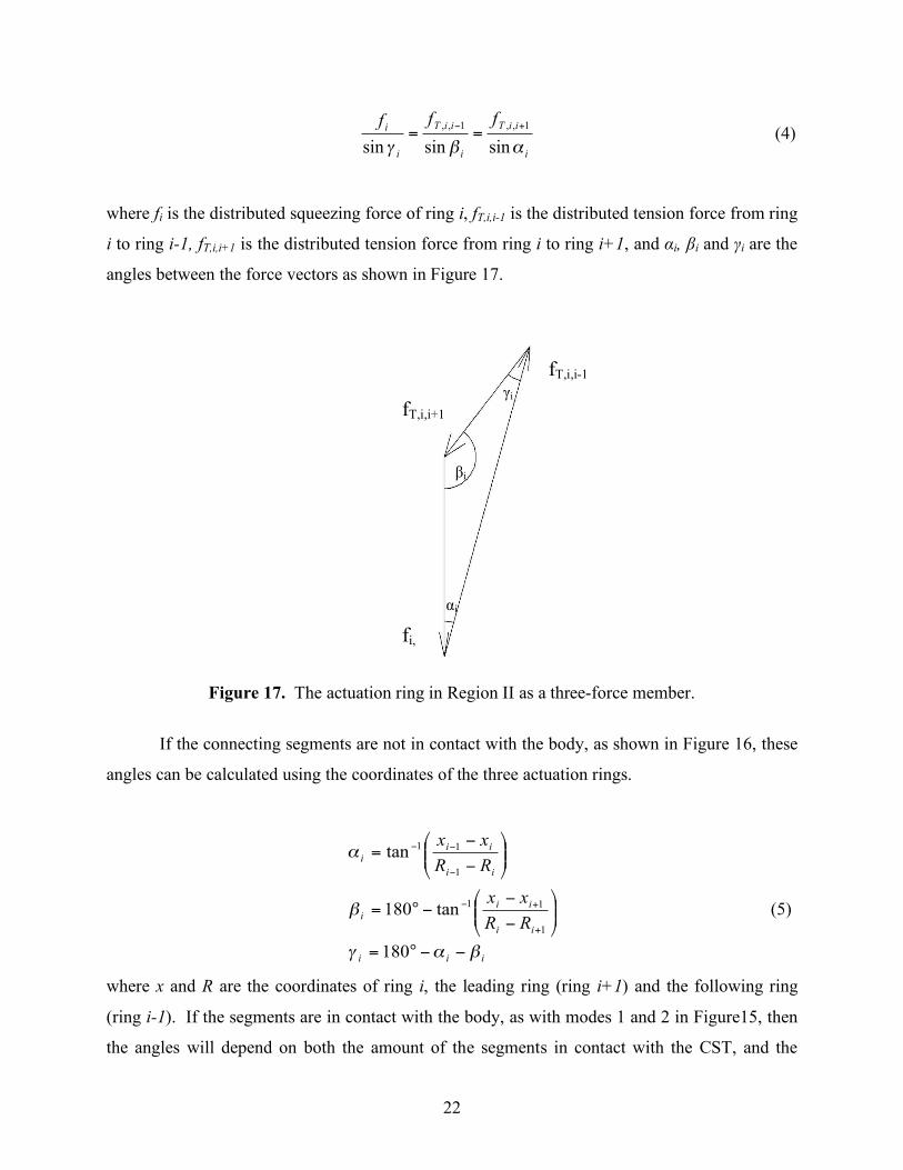
skin attached before (fT,i,i-1) and after (fT,i,i+1) the ring. Figure 17 shows the force vector polygon
for this three force member. From the law of sines the following relationship between the three
forces can be found:
22
i
iiT
i
iiT
i
ifff
!"# sinsinsin
1,,1,, +$== (4)
where fi is the distributed squeezing force of ring i, fT,i,i-1 is the distributed tension force from ring
i to ring i-1, fT,i,i+1 is the distributed tension force from ring i to ring i+1, and αi, βi and γi are the
angles between the force vectors as shown in Figure 17.
Figure 17. The actuation ring in Region II as a three-force member.
If the connecting segments are not in contact with the body, as shown in Figure 16, these
angles can be calculated using the coordinates of the three actuation rings.
iii
ii
ii
i
ii
ii
i
RR
xx
RR
xx
!"#
!
"
$$°=
%%&
'(()
*
$
$$°=
%%&
'(()
*
$
$=
+
+$
$
$$
180
tan180
tan
1
11
1
11
(5)
where x and R are the coordinates of ring i, the leading ring (ring i+1) and the following ring
(ring i-1). If the segments are in contact with the body, as with modes 1 and 2 in Figure15, then
the angles will depend on both the amount of the segments in contact with the CST, and the
αi
γi
βi
fT,i,i-1
fi,
fT,i,i+1
23
material properties of the segments and ring actuators. Therefore, the angles will have to be
redefined for mode 1 and 2, based on and their individual characteristics.
The position and output of a single ring will be determined not only by its position and
squeezing force, but also by the position and squeezing force of the next and previous rings as
well. The output force of a ring in region II will be the difference of the tension between the two
connecting segments attached to it. Thus, using Equation 4, the following equation can be
derived:
1
1
1,sin
sin
sin
sin
!
!!!=
i
ii
i
iiiR fff
"
#
"
$ (6)
To convert this distributed output force to force output of the pair of rings, it must be multiplied
by the average circumference of those rings (as shown in Equations 2 and 3).
If the rings are constrained to move along a circular profile α, β and γ can be put in terms
of the slope angle of the actuating rings:
!"
!!#$
!!%
&=
&''=
&'=
i
ii
ii
2
2
(7)
where φi is the slope angle of ring i, and Δφ is the difference in slope angle between the rings.
Using this, and Equations 1 and 6, the force output of a pair of rings can be determined in terms
of the slope angle:
( )!
!!
!!
!!
!!!!"
#
$%
&'(
) #*+
#+++$%
&'(
) #+
+*#+++=
+
sin
2
3sin)sin(2
sinsin
)sin(sin2 max
1,
max
,
max
i
i
iR
i
i
iR
iii
rR
T
rR
T
rrRF (8)
where Rmax is radius of a ring at the tip of the CST, and r is the radius of the circle the rings are
constrained to travel over. From this it can be seen that the mechanics in region II is much more
complex, and dependent on more variables than that in region I. Here the output force is
dependent on spacing of the rings, the difference in ring tension, and dimensions of the CST, not
just the slope angle itself.
24
6.1.3 Region III Region III is the area of the CST where an expanding ring pushes against the front, inner
surface. This front expanding ring will generate the propulsive force in a similar way as the
rings in Region I, but by pushing off the CST surface by the expansion of the ring.
It is important to note that since the actuator rings in this region are expanding, they will
no longer be under tension, but under compression. Flexible actuators, such as ones that use
electroactive polymers or shape memory alloys, may cause problems in buckling when put under
compression. While the rings still need to expand in order to prevent interference with the
motion over the body of the CST, it is unlikely that they will provide useful work to the system.
In some cases the actuators may also contract slightly from its nominal diameter to hold the
membrane skin and rings away from the surface of the CST to reduce friction. This may be done
if the energy loss from the friction is greater than the energy required to hold them away.
6.1.4 Region IV The final active region is Region IV, the frontal expansion region. Similar to the
relationship between Region I and Region III, the mechanics of this region behave as the inverse
of Region II. The same caveats on actuating in Region III also apply to this region. While a ring
in Region IV could potentially provide useful work input, it would also be operating in
compression thus, as in Region III, there is the potential problem of buckling. Nevertheless, the
actuating rings need to expand enough to prevent interference of motion over the CST surface.
6.2 Mechanical Advantage and Efficiency for Different Cross-section geometries As was shown in Sub-section 6.1.1 the output of a ring contracting or expanding against a
CST is dependent on friction and cross-section geometry. The mechanical advantage and
efficiency can be used to observe the force transmission characteristics and energy loss of the
mechanism over its range of motion. In this section we define mechanical advantage and
efficiency for a WSL mechanism with a CST, and present a parametric study of how various
parameters such as position, friction coefficient, and CST cross-section geometry affect the total
output force and the total output work for a CST WSL mechanism.
The mechanical advantage is used to observe how the total force output of the mechanism
changes over the ring actuator’s range of motion, for a given ring actuator contracting force. For

25
this system the mechanical advantage is defined as the ratio of the total propulsion output force F
over the actuating ring tension input force TR.
!
M.A.=F
TR (9)
Similarly, the efficiency of the system is defined as the ratio of the output work over the
input work by the actuation ring.
cT
sF
W
W
Rin
out
!"
!"==#
(10)
where Δs is the distance the actuation ring travels on its path, and Δc is the change in the
circumference of the actuation ring. The efficiency of the mechanism will show how much work
is lost through the friction between the ring actuator and the CST surface.
6.2.1 Round Cross-section, Region I In this section we observe how changing the Coulomb friction coefficient between the
actuation ring and the CST affects the mechanical advantage and efficiency in region I of the
WSL mechanism with a round cross-section over its range of motion. Figure 18 shows the
efficiency and mechanical advantage of a WSL mechanism with a single actuation ring in region
I on a semi-circular cross-section CST body (as shown in Figure 14) plotted against its travel
path length with varying friction coefficients (from 0.01 to 1.0).
26
Figure 18. Mechanical advantage and efficiency versus percent of travel for a circular cross-
section CST in Region I with varying friction coefficients.
For the case of a semi-circular cross-section CST, both mechanical advantage and
efficiency show similar trends of becoming larger as the contracting ring moves from its initial
position with values of zero, to its final position where they reach their maximum values. The
mechanical advantage and efficiency for a given friction coefficient is simply a function of the
slope angle φ and when the CST is flat, perpendicular to the radial direction of the contracting
ring, all of the “squeezing” force, f, is used against the normal force, fN, producing no output
force. When the contracting ring reaches the tip of the CST (the end of region 1 and beginning of
region II), the “squeezing” force of the ring actuator is in the contact tangential direction, thus
there is no friction loss and all of the input force is transferred into the total output force,
resulting in an efficiency of 1. At this position, the mechanical advantage also reaches its
maximum value of 2π, which is the ratio between the circumference (tangential direction) and
the radius (radial direction) of the circular cross section of the CST. This maximum value is the
same for all friction coefficients as there are no contributions from friction at this position.
The friction coefficient has a large effect on both the mechanical advantage and
efficiency of the mechanism, as can be seen in Figure 18. The lower the friction coefficient is the
faster the efficiency approaches the maximum value, and the sooner it can produce useful work.
From these two figures we can observe that a single contracting ring actuator cannot produce any
useful work until its reaches a certain critical point (where the curve intersects the x-axis.) This is
27
the point where the propulsion force from the tension in the ring actuator can start to overcome
the friction force resulting from the normal component of the squeezing force. The location of
this critical point varies from the beginning of the range of motion, for a very small friction
coefficient, to half way along the active surface of the cross section, for the maximum coefficient
of 1, as this is where the slope angle φ equals the inverse tangent of the friction coefficient.
From these observations, the optimal actuation strategy for the many actuation rings (how
much tension in each actuation ring in which sequence) can be developed to maximize the output
work. Also, in the design phase, insights obtained from this can be applied in deciding the
distribution of the actuating rings in the membrane skin to ensure smooth motion of the
mechanism, and minimize the number of actuators.
6.2.2 Straight Line Cross-section, Region I For a strait line (or triangular) cross-section CST geometry the friction and the slope
angle φ are the only variables that influence the efficiency and mechanical advantage, as with the
round cross-section CST geometry as shown earlier. However, unlike the circular cross-section
case, a strait line cross-section has a constant slope; therefore, the mechanical advantage and
efficiency are constant for a given slope and friction coefficient, as can be seen in Figures 19 and
20. Figure 19 shows the mechanical advantage and efficiency for various friction coefficients. In
these plots the slope angle φ is held constant at 45°. Figure 20 shows the mechanical advantage
and efficiency for various slope angles. These plots are shown without friction. From Figure 20
it can be seen that the most efficient cross-section is one with a slope angle of 90°, a vertical
drop. This is the expected result, as when the slope angle is 90° all of the applied force is used
for actuation.
28
Figure 19. Mechanical advantage and efficiency of a strait line cross-section CST, for varying
friction and a constant slope angle of 45°.
Figure 20. Mechanical advantage and efficiency of a strait line cross-section CST, for varying
slope angles and a friction coefficient of 0.
With a straight line cross-section there will be two points where Region I starts and ends.
At these points there may be a need for a rounded region of the cross-section for a smooth
motion of the membrane skin moving over the surface of the CST. Also, depending on the
output characteristics of the selected actuators, it may be preferable to have a mixture of cross-
section geometries, with high and low mechanical advantage. Thus for an efficient cross-section
geometry for a CST, a combination of strait line and round cross-sections may be preferable.
29
6.2.3 Composite Cross-section, Region I In the previous subsections, a CST with a semicircular cross-section and a straight line
cross-section were analyzed to see how various parameters affect the efficiency of the
mechanism. As the efficiency and mechanical advantage depend on the slop angle at the location
of the actuation ring, among other parameters, a CST with a combination of cross-sections can
be utilized to increase the area of active region and to maximize the overall performance of the
mechanism.
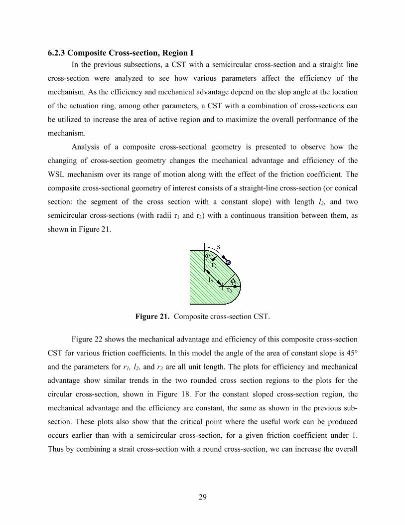
Analysis of a composite cross-sectional geometry is presented to observe how the
changing of cross-section geometry changes the mechanical advantage and efficiency of the
WSL mechanism over its range of motion along with the effect of the friction coefficient. The
composite cross-sectional geometry of interest consists of a straight-line cross-section (or conical
section: the segment of the cross section with a constant slope) with length l2, and two
semicircular cross-sections (with radii r1 and r3) with a continuous transition between them, as
shown in Figure 21.
Figure 21. Composite cross-section CST.
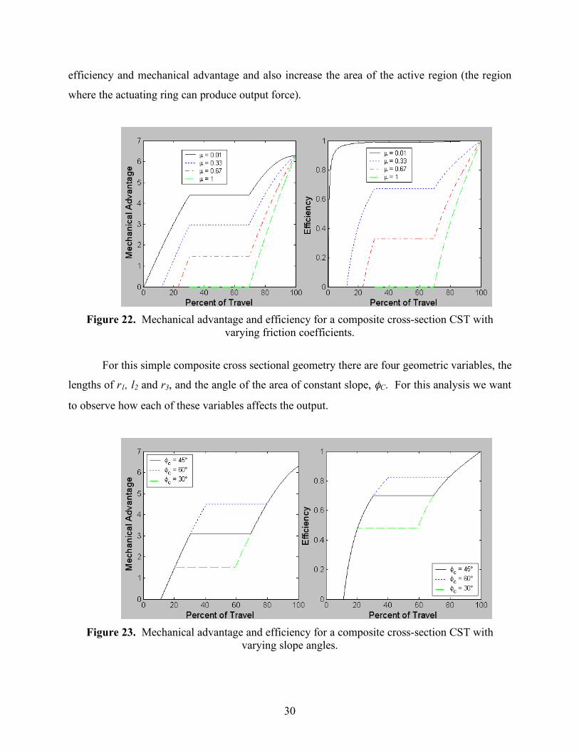
Figure 22 shows the mechanical advantage and efficiency of this composite cross-section
CST for various friction coefficients. In this model the angle of the area of constant slope is 45°
and the parameters for r1, l2, and r3 are all unit length. The plots for efficiency and mechanical
advantage show similar trends in the two rounded cross section regions to the plots for the
circular cross-section, shown in Figure 18. For the constant sloped cross-section region, the
mechanical advantage and the efficiency are constant, the same as shown in the previous sub-
section. These plots also show that the critical point where the useful work can be produced
occurs earlier than with a semicircular cross-section, for a given friction coefficient under 1.
Thus by combining a strait cross-section with a round cross-section, we can increase the overall
30
efficiency and mechanical advantage and also increase the area of the active region (the region
where the actuating ring can produce output force).
Figure 22. Mechanical advantage and efficiency for a composite cross-section CST with
varying friction coefficients.
For this simple composite cross sectional geometry there are four geometric variables, the
lengths of r1, l2 and r3, and the angle of the area of constant slope, φC. For this analysis we want
to observe how each of these variables affects the output.
Figure 23. Mechanical advantage and efficiency for a composite cross-section CST with
varying slope angles.
31
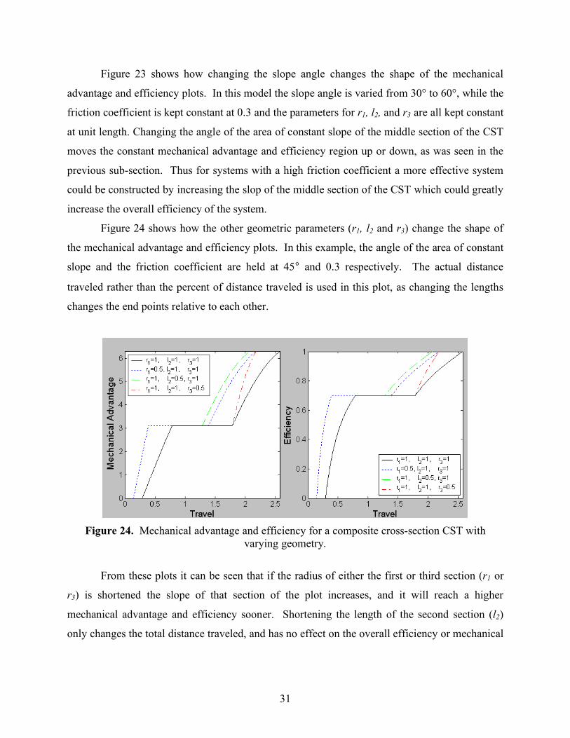
Figure 23 shows how changing the slope angle changes the shape of the mechanical
advantage and efficiency plots. In this model the slope angle is varied from 30° to 60°, while the
friction coefficient is kept constant at 0.3 and the parameters for r1, l2, and r3 are all kept constant
at unit length. Changing the angle of the area of constant slope of the middle section of the CST
moves the constant mechanical advantage and efficiency region up or down, as was seen in the
previous sub-section. Thus for systems with a high friction coefficient a more effective system
could be constructed by increasing the slop of the middle section of the CST which could greatly
increase the overall efficiency of the system.
Figure 24 shows how the other geometric parameters (r1, l2 and r3) change the shape of
the mechanical advantage and efficiency plots. In this example, the angle of the area of constant
slope and the friction coefficient are held at 45° and 0.3 respectively. The actual distance
traveled rather than the percent of distance traveled is used in this plot, as changing the lengths
changes the end points relative to each other.
Figure 24. Mechanical advantage and efficiency for a composite cross-section CST with
varying geometry.
From these plots it can be seen that if the radius of either the first or third section (r1 or
r3) is shortened the slope of that section of the plot increases, and it will reach a higher
mechanical advantage and efficiency sooner. Shortening the length of the second section (l2)
only changes the total distance traveled, and has no effect on the overall efficiency or mechanical
32
advantage. Again, this information will be useful in designing future CST WSL mechanisms to
maximize the performance of the system.
6.2.4 Region II
As the force output for region II is based on the difference in tension between the
actuating rings connected by a membrane segment, the mechanical advantage of rings in region
II is calculated using Fi from Equation 8, and dividing by the average of the input forces of the
two actuating rings:
( ) 21,, !+
=iRiR
i
i
TT
FMA (11)
Expanding this equation in terms of Equations 1, 7 and 8 results in the following equation:
( )( )
!!!!
"
#
$$$$
%
&
'((
!"
#$%
& ')(
((
!"
#$%
& '(
'
'(((=
**
**
*
**
*
***+
i
i
i
i
ii
i
rRrR
rrRMA
sin
2
3sin
sin
2sin
sin
)sin(sin2
maxmax
max (12)
Figure 25 shows the mechanical advantage of a round cross-section CST in region II,
with a constant ring tension (TR). In this plot the rings move along a circle with a radius of unit
length, the radius of the inside of the CST (the minimum ring radius) is unit length, and the angle
between the rings varies from 1° to 30°.
33
Figure 25. Mechanical advantage of the round cross-section, region II, mode 3, with unit ring
tensions, and varying ring spacing.
In this plot, instead of using the percent travel, mechanical advantage is plotted with
respect to the slope angle of ring i, and each plot begins when ring i-1 leaves region I. As with
region I, the maximum mechanical advantage occurs when the ring is closest to the tip, and the
minimum occurs when the ring is closest to the inside of the body. From this plot it can be seen
that as the spacing between the rings increases, the overall mechanical advantage increases. This
is because the larger ring spacing increases the angle between the rings, which increases the
difference in tension betweens rings i and i-1.
As with modes 1 and 2 (shown in Figure 15), Equations 4-8 are only valid if the ring of
interest is a three force member. Therefore, we can only look at the round cross-section, as the
forces for triangular or composite cross-sections will include a straight section, and will not form
a valid force triangle. If a valid force triangle is not formed, the forces in the segment will be
statically indeterminate, meaning that we would have to look at specifics of materials and
actuators, which is beyond the scope of this research.
34
6.2.5 Region III and IV
Regions III and IV, the front expanding ring area, will have the same mechanical
advantage and efficiency behavior as the rings in Regions I and II respectively. Again, it is
important to note that since the actuator rings in this region are expanding, they will no longer be
under tension, but under compression. Flexible actuators, such as ones that use electroactive
polymers or shape memory alloys, could be problematic as they could buckle while under
compression. The rings still need to expand in order to prevent interference with the motion over
the body of the CST; however, it is unlikely that they will provide useful work to the system.
6.3 Analysis and Simulation for the CST Model System
6.3.1 Displacement Constraints of the Actuation Rings for the CST Model System
As each ring moves across the surface of the CST it will need to follow a set pattern. The
pattern for a circular cross-section is shown in Figure 26. The ring starts on the outer surface of
the CST, contracts over Region I (x = 0 to 0.5) and contracts inside Region II (x = 0.5 to 1.0),
then passes through the inner surface of the CST (x = 1.0 to 2.0). It then expands inside Region
III (x = 2.0 to 2.5), expands over region four (x = 2.5 to 3.0), and returns, through Region IV (x =
3.0 to 4.0), to the beginning of Region I (x = 0).
35
Figure 26. Ring radius versus position for a single ring over a circular cross-section CST.
This information will be useful for design of a future controller based on the position and
displacement of the individual ring actuators. A position based controller is often preferable to a
force based controller, as position can be easily measured, while force often has to be inferred.
6.3.2 Input Tension Required for the Actuation Rings for the CST Model System
The CST model consists of multiple actuator rings, expanding and contracting over four
distinct regions (as defined in Section 6.1). In order to find the output of the entire CST model
system, the sum of the force output of each group of active rings must be determined. This will
depend on the cross-sectional geometry of the CST, as well as the friction and force output
characteristics of the actuators.
The output of the rings in regions I and III can be determined by calculating the force
output for each of the rings (using Equations 2 and 3), and summing the results. The output of
region II and IV will depend on the interaction between the rings. Again, regions III and IV will
36
either not be active, as they will be operating in compression, or they will behave the same as
regions I and II respectively.
In order to determine the required force input to produce a uniform force output, the
required tension input for a unit force output has been plotted in Figure 27. This is the inverse of
the mechanical advantage.
Figure 27. Tension input required in region I, for a unit force output, frictionless.
From this figure it can be seen that in order for a single ring to provide a unit output, a
ring just starting to move into region I will require a near infinite force input, as this is because
all of the force will be acting in the direction normal to the motion of the skin. As the ring
approaches the tip of the CST more of the force is acting in the direction of the skin. A similar
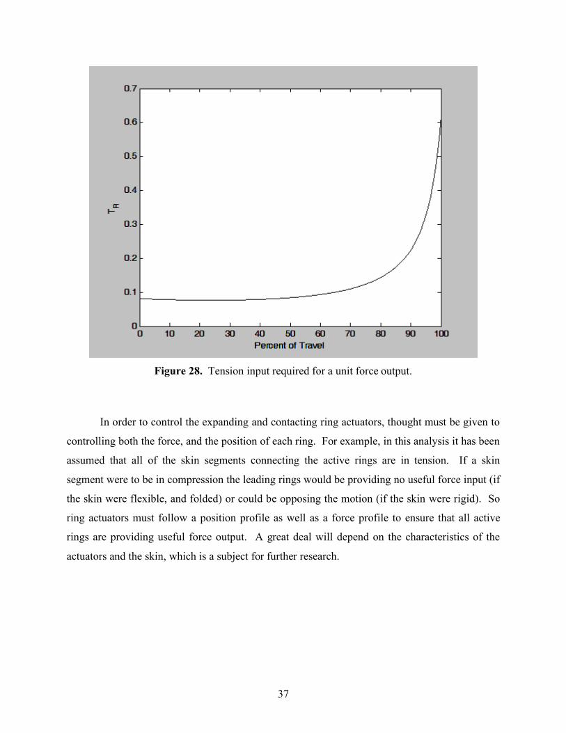
pattern can be seen when plotting the required tension input for a pair of rings in region II in
Figure 28. Minimal input is required near the tip, increasing as the rings approach the inside
inactive region.
37
Figure 28. Tension input required for a unit force output.
In order to control the expanding and contacting ring actuators, thought must be given to
controlling both the force, and the position of each ring. For example, in this analysis it has been
assumed that all of the skin segments connecting the active rings are in tension. If a skin
segment were to be in compression the leading rings would be providing no useful force input (if
the skin were flexible, and folded) or could be opposing the motion (if the skin were rigid). So
ring actuators must follow a position profile as well as a force profile to ensure that all active
rings are providing useful force output. A great deal will depend on the characteristics of the
actuators and the skin, which is a subject for further research.
38
Chapter 7
Conclusions and Future Work
The purpose of this research was to investigate a new, fundamental locomotion
mechanism based on the motility of monopodial, single-celled organisms, like amoebas. In order
to do this the theories of amoeboid motility were studied, and from these the different models for
Whole Skin Locomotion were developed. These models are the rear contracting Concentric
Solid Tube (CST), the front expanding CST, the wave CST, and the Fluid Filled Toroid (FFT).
While these models behave in a similar way to the cytoplasmic streaming in amoebas they are
not the same. We are not looking to mimic the amoeba, merely using it for inspiration.
Feasibility experiments were performed using the FFT model. The first experiment was
carried out using a pre-tensioned elastic skin, and the second experiment used contracting tension
cords. These experiments showed that WSL mechanism is feasible, and with a continuously
contracting rear surface it will be able to move continuously.
The CST model was studied in depth, looking at the mechanics of expanding and
contracting actuating rings over different regions of the body, and looking at the mechanical
advantage and efficiency of different cross-section geometries. From this it was found that the
most efficient geometry would be a square cross-section. However, this may not always be the
best actuation geometry, as it also has a high mechanical advantage and therefore a short stroke
length.
The goal of this research was not to design a Whole Skin Locomotion (WSL) robot, but
to develop the mechanics of one of the possible WSL mechanisms, the Concentric Solid Tube
(CST) model and its variations. In order to design and build a CST based robot further research
must be done on actuators that are capable of acting as expanding and/or contracting rings.
Research will also need to be done into skin materials, for the CST analysis it was assumed that
the segments connecting the rings were rigid. The advantages and disadvantages of an elastic
skin should also be studied. Future work will also include the analysis of the FFT model, which
hold great promise, and behave in a unique way.
Whole Skin Locomotion is an entirely new way for robots to move, inspired by the way
an amoeba moves. While much work remains before true working prototypes can be built, this
39
new class of mechanism has great potential for getting robots into unstructured environments
such as rubble from a collapsed building, or the inside of the human body.
40
References [1] Laney, D., and Hong, D. W., “Kinematic Analysis of a Novel Rimless Wheel with
Independently Actuated Spokes,” 29th ASME Mechanisms and Robotics Conference, Long Beach, California, September 24- September 28, 2005.
[2] Saranli, U., Buehler, M., and Koditschek, D.E. “RHex: A Simple and Highly Mobile
Hexapod Robot,” International Journal of Robotics Research 20, July 2001, pp. 616-631. [3] Morrey, J. M., Lambrecht, B., Horchler, A. D., Ritzman, R. E., Quinn, R. D., “Highly
Mobile and Robust Small Quadruped Robot,” Proceedings of the 2003 IEEE/RSJ International Conference on Intelligent Robots and Systems, Las Vegas, NV, Oct. 2003, pp. 82-87.
[4] Murphy, R. R., “Trial by Fire: Activities of the rescue robots at the World Trade Center
from 11-21 September 2001,” IEEE Robotics and Automation Magazine, Vol. 11, No. 3, September 2004.
[5] Blackburn, M. R., Everett, H. R., and Laird, R. T., “After Action Report to the Joint
Program Office: Center for the Robotic Assisted Search and Rescue (CRASAR) Related Efforts at the World Trade Center,” Technical Document 3141, Space and Naval Warfare Systems Center, San Diego, CA, August 2002.
[6] Ingram, M. and Hong, D. W., “Whole Skin Locomotion Inspired by Amoeboid Motility
Mechanisms”, 29th ASME Mechanisms and Robotics Conference, Long Beach, California, September 24- September 28, 2005.
[7] Hirose, S. and Fukushima, E.F., “Snakes and Strings: New Robotic Components for
Rescue Operations,” International Journal of Robotics Research, Vol. 23, No. 4-5, April-May 2004, pp. 341-349.
[8] Takayama, T., and Hirose, S., “Development of Souryu-I and II,” Proceedings of the
TITech COE/Super Mechano-Systems Symposium, pp. HRS-1, 2001. [9] Kassim, I., Ng, W. S., Feng, G., and Phee, S. J., “Review of Locomotion Techniques for
Robotic Colonoscopy,” Proceedings of the IEEE International Conference on Robotics & Automation, Taiwan, September 14-19, 2003, pp. 1086 – 1091.
[10] Phee, S. J., Ng, W. S., Chen, I. M. & Seow-Choen, F., “Development of new locomotive
concepts to be used in automation of colonoscopy,” Proceedings of 9th International Conference for Biomedical Engineering, Singapore, pp. 87–92, New York, 1997.
[11] Menciassi, A., Stefanini, C., Gorini, S., Pernorio, G., Kim, B., Park, J. O., and Dario, P.,
“Locomotion of a Legged Capsule in the Gastrointestinal Tract: Theoretical Study and Preliminary Technological Results,” Proceedings of the 26th Annual International
41
Conference of the IEEE EMBS, San Francisco, CA, USA, September 1-5, 2004, pp. 2767-2770.
[12] Hong, D. W., “A Biologically Inspired Whole Skin Locomotion Strategy for Mobile
Robots”, US-Korea Conference on Science, Technology and Entrepreneurship (UKC2005), Mechanical Engineering & Robotics Symposium, University of California, Irvine, California, August 11-13, 2005
[13] Nakabo, Y., Mukai, T., and Asaka, K., “Bio-Mimetic Soft Robots with Artificial
Muscles,” SPIE Int. Symp. Smart Materials, Nano- and Micro-Smart Systems, conference, Dec 12 -15, 2004, Australia, Proceedings of SPIE, Vol. 5648, pp. 132 – 144.
[14] Melhuish, C., Adamatzky, A., Kennedy, B., “Biologically Inspired Robots,” Proceedings
of SPIE, Smart Structures and Materials 2002: Electroactive Polymer Actuators and Devices (EAPAD), July 2001, Vol. 4329, pp. 16-27.
[15] Wingert, A., Lichter, M. D., Dubowsky, S., Hafez, M., “Hyper-redundant robot
manipulators actuated by optimized binary-dielectric polymers,” Proceedings of SPIE, Smart Structures and Materials 2002: Electroactive Polymer Actuators and Devices (EAPAD), July 2002, Vol. 4695, pp. 415-423.
[16] Lackie, J. M., 1986, “Cell Movement and Cell Behavior,” Allen and Unwin, London. [17] Allen, R. D., 1973, “Biophysical Aspects of Pseudopodium Formation and Retraction,”
The Biology of Amoeba, Ed. Jeon, K. W., Academic Press, Inc., New York and London, pp. 201-247.
[18] Paljug, E. Ohm, T. Hayati, S., “The JPL Serpentine Robot: a 12-DOF system for
inspection,” Proc., 1995 IEEE International Conference on Robotics and Automation, Nagoya, Japan, May 1995.
[19] Klaassen, B., Paap, K. L., “GMD-SNAKE2: A Snake-Like Robot Driven by Wheels and
a Method for Motion Control,” Proceedings of the 1999 IEEE/RSJ International Conference on Intelligent Robots and Systems, Detroit, MI, USA, May, 1999.
[20] L. Phee, D. Accoto, A. Menciassi, C. Stefanini, M.C. Carrozza, P. Dario, “ Analysis and
Development of Locomotion Devices for the Gastrointestinal Tract”, IEEE Transactions on Biomedical Engineering, Vol. 49, No. 6, June 2002.
[21] Phee, L., Menciassi, A., Gorini, S., Pernorio, G., Arena, A. & Dario, P., “An innovative
locomotion principle for minirobots moving in the gastrointestinal tract,” Proceedings of the International Conference on Robotics & Automation, Washington, DC, Vol. 2, pp. 1125–1130, 2002.
42
[22] Menciassi, A. and Dario, P., “Bio-inspired solutions for locomotion in the gastrointestinal tract: background and perspectives,” Philosophical Transactions of the Royal Society, 2003, October Vol. 15, No. 61, pp. 2287-2298.
[23] Dario, P., Ciarletta, P., Menciassi, A., and Kim, B., 2004 “Modeling and Experimental
Validation of the Locomotion of Endoscopic Robots in the Colon,” Int. Jnl. of Robotics Research, 23, pp. 549-556.
[24] Slatkin, A.B. Burdick, J. Grundfest, W., “The development of a robotic endoscope,”
Proceedings of the 1995 IEEE/RSJ International Conference on Intelligent Robots and Systems, Pittsburgh, PA , USA, Aug. 1995.
[25] Roh, S., Choi, H., “Differential-Drive In-Pipe Robot for Moving Inside Urban Gas
Pipelines,” IEEE Transactions on Robotics, vol. 21, issue 1, Feb. 2005, pp. 1–17. [26] Breedveld, P., van der Kouwe, D. E., van Gorp, M. A. J.,, “Locomotion Through the
Intestine By Means of Rolling Stents,” Proc. of ASME 2004 Design Engineering Technical Conferences, Salt Lake City, UT., 2004.
[27] Flynn A. M., et al., “Tomorrow’s Surgery: Micromotors and Microrobots for Minimally
Invasive Procedures,” Journal of Minimally Invasive Therapy and Allied Technologies, Vol. 4, 1998, pp. 343-352.
[28] Long, G., Anderson, J., and Borenstein, J., “The Kinematic Design of the OmniPede: A
New Approach to Obstacle Traversion,” Proc., 2002 IEEE International Conference on Robotics and Automation, Washington, D.C., pp. 714-719, 2002.
[29] Schempf, H., “Aurora - Minimalist Design for Tracked Locomotion,” Robotics Research,
R.A. JArvis and A. Zemlinsky (EDs.), Springer Verlag Berlin, 453-465, 2003. [30] Allen, R. D., “Motility,” J. Cell Biol., 91 (3 Pt 2), pp. 148s-155s, 1981. [31] Taylor, D. L., Condeelis, J. S., Moore, P. L., and Allen, R. D., “The Contractile Basis of
Amoeboid Movement,” J. Cell Biol., 59, pp. 378-394, 1973. [32] Lorch, I. J., “Some Historical Aspects of Amoeba Studies,” The Biology of Amoeba, Ed.
Jeon, K. W., Academic Press, Inc., New York and London, pp. 1-36, 1973. [33] Ecker, A., “Zur lehre vom bau und leben der contractilen substanz der niedersten thiere,”
Z. Wiss. Zool. Abt. A (abbreviation of: Zeitschrift fur Zellforschung und mikroskopische Anatomie), 1, pp. 218-245, 1849.
[34] Rinaldi, R. and Opas, M., “Graphs of Contracting Glycerinated Amoeba proteus,”
Nature, 260, 525-526, 1976.
43
[35] Allen, R. D., Cooledge, J. W., and Hall, P. J., “Streaming in cytoplasm dissociated from the giant amoeba, Chaos chaos,” Nature, 187, pp. 896-899, 1960.
[36] Allen, R. D., Francis, D. W., and Zeh, R., “Direct test of the positive pressure gradient
theory of pseudopod extension and retraction in amoebae,” Science, 174, pp. 1237-1240, 1971.
[37] Cullen, K. J., and Allen, R. D., “A laser microbeam study of amoeboid movement,” Exp.
Cell Res. 127, pp. 1-10, 1980. [38] Pellegrino, S., Kebadze, E., Lefort, T., and Watt, A. M., “Low-Cost Hinge for
Deployable Structures,” Technical Report, University of Cambridge, 2002. [39] Yoseph Bar-Cohen (Editor), “Electroactive Polymer (EAP) Actuators as Artificial
Muscles: Reality, Potential, and Challenges,” Second Edition, SPIE Vol. PM136. [40] Cohen, Y., Bao, X., Sherrit, S. & Lih, S. S., “Characterization of the electromechanical
properties of ionomeric polymer–metal composites,” Proceedings of SPIE Smart Structures Materials Symp., NDE Conference, San Diego, CA, March 18–20, 2002, pp. 219–238. Bellingham, WA.
[41] Bar-Cohen, Y., “EAP History, Current Status, and Infrastructure,” Electroactive Polymer
(EAP) Actuators as Artificial Muscles: Reality, Potential, and Challenges, Bar-Cohen, Y., ed., SPIE – The International Society for Optical Engineering, Bellingham, WA, pp. 3-44, 2001.