Embed Size (px)
Citation preview
WHITEWATER® FILTER/DRIP SYSTEM MODEL 8115 / 8230
P.O. BOX 969, DENHAM SPRINGS, LA 70727 (225) 665-6162 – Telephone (225) 664-9467 – Fax Revised 03/01/06
DISTRIBUTOR AND HOMEOWNER NOTES
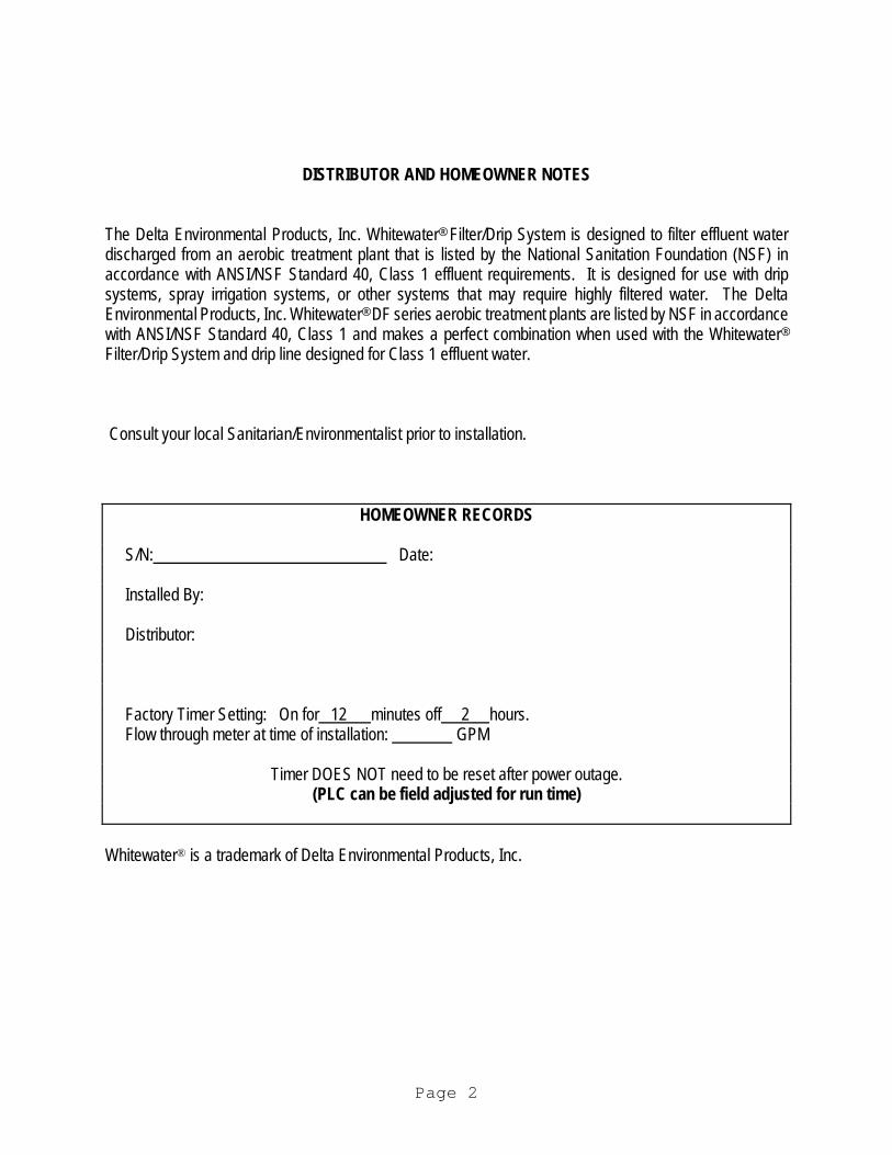
The Delta Environmental Products, Inc. Whitewater® Filter/Drip System is designed to filter effluent water discharged from an aerobic treatment plant that is listed by the National Sanitation Foundation (NSF) in accordance with ANSI/NSF Standard 40, Class 1 effluent requirements. It is designed for use with drip systems, spray irrigation systems, or other systems that may require highly filtered water. The Delta Environmental Products, Inc. Whitewater® DF series aerobic treatment plants are listed by NSF in accordance with ANSI/NSF Standard 40, Class 1 and makes a perfect combination when used with the Whitewater®
Filter/Drip System and drip line designed for Class 1 effluent water. Consult your local Sanitarian/Environmentalist prior to installation. HOMEOWNER RECORDS S/N: Date: Installed By: Distributor: Factory Timer Setting: On for 12 minutes off 2 hours. Flow through meter at time of installation: GPM Timer DOES NOT need to be reset after power outage. (PLC can be field adjusted for run time) Whitewater® is a trademark of Delta Environmental Products, Inc.
Page 2
CARE AND OPERATION INSTRUCTIONS
The Whitewater® System has been designed and built to provide long term, reliable and efficient service. Once the unit has been installed (see installation instructions) the unit will operate with a minimum amount of attention. The following checks should be made periodically as described: CAUTION: USE LATEX PROTECTIVE GLOVES WHEN HANDLING EFFLUENT WASTEWATER. AVOID GETTING ANY EFFLUENT WATER ON YOU. WASH UP WITH ANTI-BACTERIAL SOAP WHEN FINISHED. Daily: - Owner/Operator Check the alarms on both the treatment plant and dosing system. The treatment plant alarm
comes on when the air supply system has malfunctioned. If the alarm is activated, check for a blown fuse or thrown circuit breaker. Check air compressor to be sure it is operating. Once accustomed to the soft humming sound of a properly operating unit, any unusual noise is an indication of malfunction. If an unusual noise is detected or total failure is observed, call your local dealer for service.
Weekly: - Owner/Operator
Check the treatment plant for offensive odor.
Check for water leakage at the ground level boxes that house the components of the filter system.
If such conditions should develop, call your local dealer for service.
6 Months: - Dealer Service
Check the air filter on the air compressor. Rinse with warm water if necessary. Check the screen filter in the filter system. Rinse with clean water if necessary.
Periodically: Solids Removal - Refer to the Whitewater® Treatment Plant Maintenance Manual
DURING THIS PROCEDURE IT IS IMPORTANT THAT CARE IS TAKEN TO PREVENT ANY SOLIDS FROM DISCHARGING INTO THE DOSING TANK.
During pump out of treatment plant, pump out the lower 25 percent of the dosing tank to remove any solids that would have accumulated on the bottom
Any sludge removed from system must be disposed of according to all state, local, and federal regulatory requirements.
The alarm to the dosing tank is activated when there is a high water situation in the dosing tank. This could indicate a problem with the filter system, dosing pump, or pump float level switches. Observe if dosing pump is operational. Turn the Hand-Off-Auto switch located in the control panel to the hand position. This will override the PLC timer and turn the pump on if
Page 3
operational, there is a 2 minute delay before pump start. Observe the water meter located in the filter box for flow. If the flow is less than that at the time of installation, it is possible the filter requires cleaning. Disconnect power from the filter control panel. The filter is located in the filter box. Unscrew the filter canisters and remove the screen element in the filter housing. Wash filter screen with clean water and reinstall into the canister. Turn the switch to the hand position and observe the water meter, again there is a 2 minute time delay before pump run. Flow would have been reduced if the filter were excessively dirty. After a period of time, observe if alarm stops sounding. This will indicate whether or not the system has returned to normal operation. Turn the switch back to the automatic position. (One revolution of the water meter is 10 gallons)
If no flow has been observed, call your local dealer for service.
CAUTION: EXCESSIVE MANUAL OVERRIDE MAY CAUSE WATER TO SURFACE AT THE GRID SYSTEM. MANUAL OVERRIDE MUST NOT EXCEED 10 MINUTES EVERY 2 HOURS.
Note - To keep maintenance to a minimum and ensure high effluent quality, the following items
should not be permitted to enter the system.
-Strong disinfectants or bleaches, other than small amounts normally utilized in day to day cleaning and laundry (be conservative). Use low-sudsing, low phosphates and biodegradable laundry detergents.
-Discharge from water softener.
Page 4
-Any type of oils, greases, or other chemical wastes.
-Disposable baby diapers and wipes.
-Sanitary napkins, condoms or other similar devices.
-Hair, bandages, rags, or string.
-Latex, plastic, or metallic objects.
-Coffee grounds or cigarette butts.
-Mud or sticks.
-Paper towels, napkins or Kleenex.
-Excessive use of water over the design flow of the system, or organic overloading in excess of design parameters.
The proper operation of this or any other home sewage system depends upon proper organic loading and the life of the microorganisms inside the system. Delta is not responsible for the in-field operation of the system, other than the mechanical and structural workings of the system itself. We cannot control the amount of harsh chemicals or other harmful substances that may be discharged into the system by the occupants of a household. HOW THE WHITEWATER® FILTER SYSTEM WORKS
Page 5
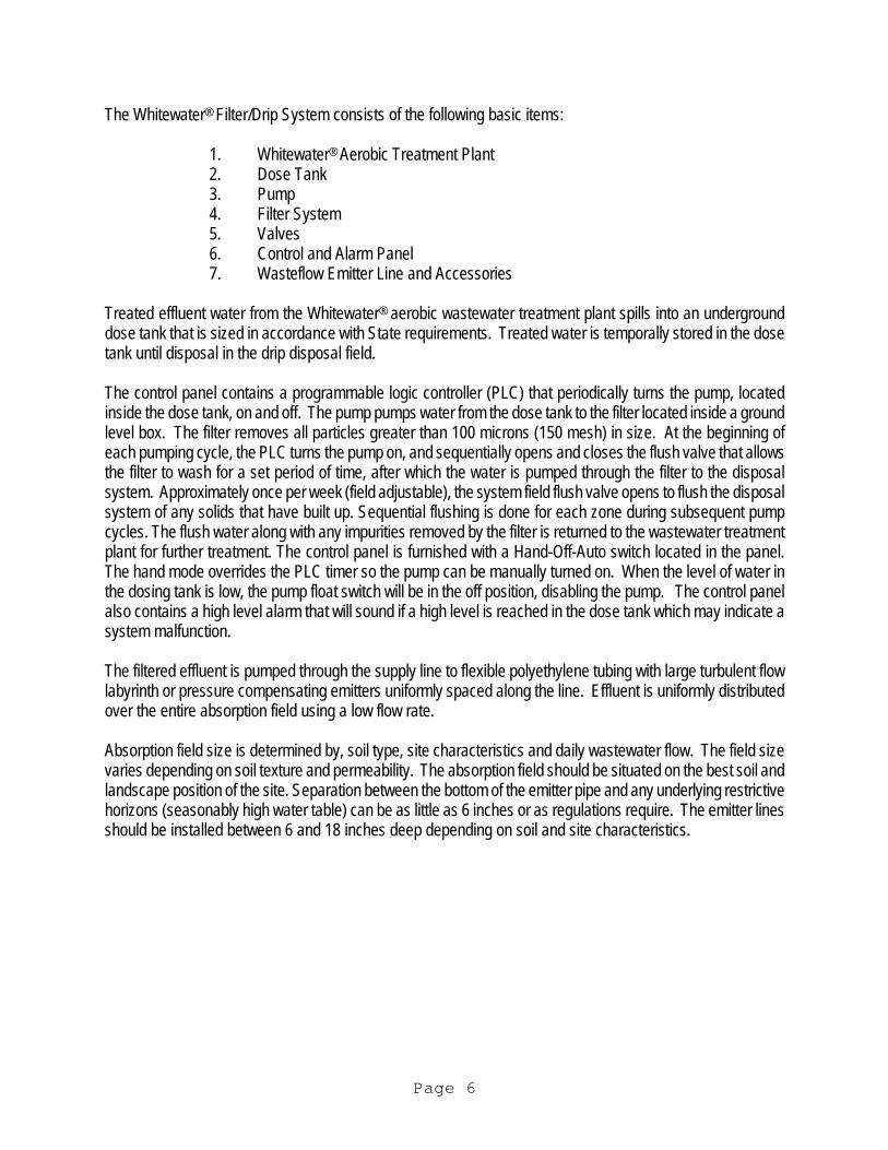
The Whitewater® Filter/Drip System consists of the following basic items:
1. Whitewater® Aerobic Treatment Plant 2. Dose Tank 3. Pump 4. Filter System 5. Valves 6. Control and Alarm Panel 7. Wasteflow Emitter Line and Accessories
Treated effluent water from the Whitewater® aerobic wastewater treatment plant spills into an underground dose tank that is sized in accordance with State requirements. Treated water is temporally stored in the dose tank until disposal in the drip disposal field. The control panel contains a programmable logic controller (PLC) that periodically turns the pump, located inside the dose tank, on and off. The pump pumps water from the dose tank to the filter located inside a ground level box. The filter removes all particles greater than 100 microns (150 mesh) in size. At the beginning of each pumping cycle, the PLC turns the pump on, and sequentially opens and closes the flush valve that allows the filter to wash for a set period of time, after which the water is pumped through the filter to the disposal system. Approximately once per week (field adjustable), the system field flush valve opens to flush the disposal system of any solids that have built up. Sequential flushing is done for each zone during subsequent pump cycles. The flush water along with any impurities removed by the filter is returned to the wastewater treatment plant for further treatment. The control panel is furnished with a Hand-Off-Auto switch located in the panel. The hand mode overrides the PLC timer so the pump can be manually turned on. When the level of water in the dosing tank is low, the pump float switch will be in the off position, disabling the pump. The control panel also contains a high level alarm that will sound if a high level is reached in the dose tank which may indicate a system malfunction. The filtered effluent is pumped through the supply line to flexible polyethylene tubing with large turbulent flow labyrinth or pressure compensating emitters uniformly spaced along the line. Effluent is uniformly distributed over the entire absorption field using a low flow rate. Absorption field size is determined by, soil type, site characteristics and daily wastewater flow. The field size varies depending on soil texture and permeability. The absorption field should be situated on the best soil and landscape position of the site. Separation between the bottom of the emitter pipe and any underlying restrictive horizons (seasonably high water table) can be as little as 6 inches or as regulations require. The emitter lines should be installed between 6 and 18 inches deep depending on soil and site characteristics.
Page 6
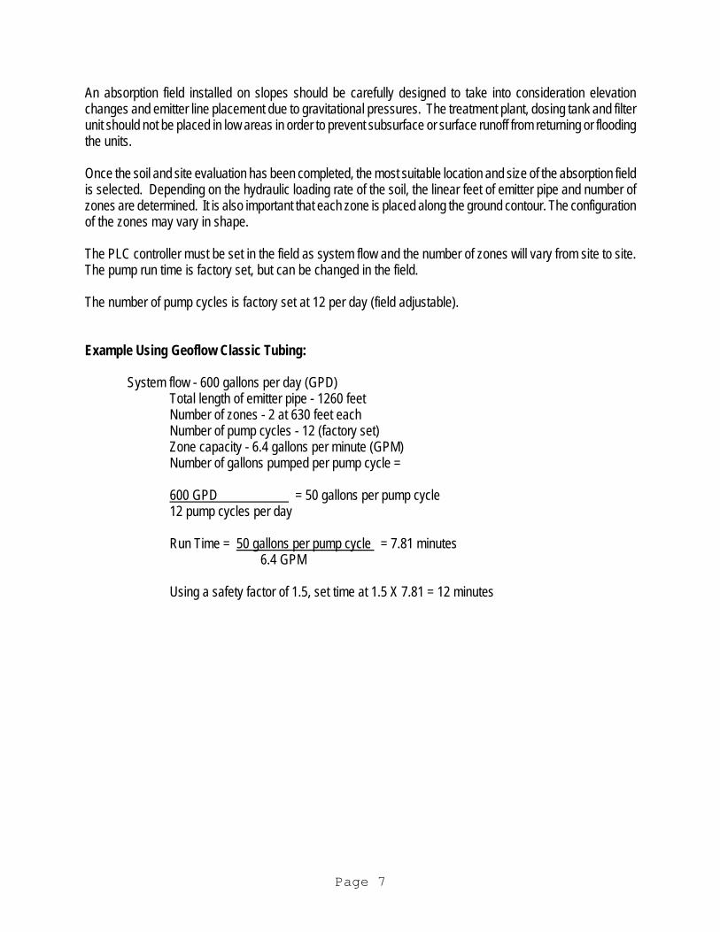
An absorption field installed on slopes should be carefully designed to take into consideration elevation changes and emitter line placement due to gravitational pressures. The treatment plant, dosing tank and filter unit should not be placed in low areas in order to prevent subsurface or surface runoff from returning or flooding the units. Once the soil and site evaluation has been completed, the most suitable location and size of the absorption field is selected. Depending on the hydraulic loading rate of the soil, the linear feet of emitter pipe and number of zones are determined. It is also important that each zone is placed along the ground contour. The configuration of the zones may vary in shape. The PLC controller must be set in the field as system flow and the number of zones will vary from site to site. The pump run time is factory set, but can be changed in the field. The number of pump cycles is factory set at 12 per day (field adjustable). Example Using Geoflow Classic Tubing: System flow - 600 gallons per day (GPD)
Total length of emitter pipe - 1260 feet Number of zones - 2 at 630 feet each Number of pump cycles - 12 (factory set) Zone capacity - 6.4 gallons per minute (GPM) Number of gallons pumped per pump cycle =
600 GPD = 50 gallons per pump cycle 12 pump cycles per day
Run Time = 50 gallons per pump cycle = 7.81 minutes
6.4 GPM
Using a safety factor of 1.5, set time at 1.5 X 7.81 = 12 minutes
Page 7

Page 8
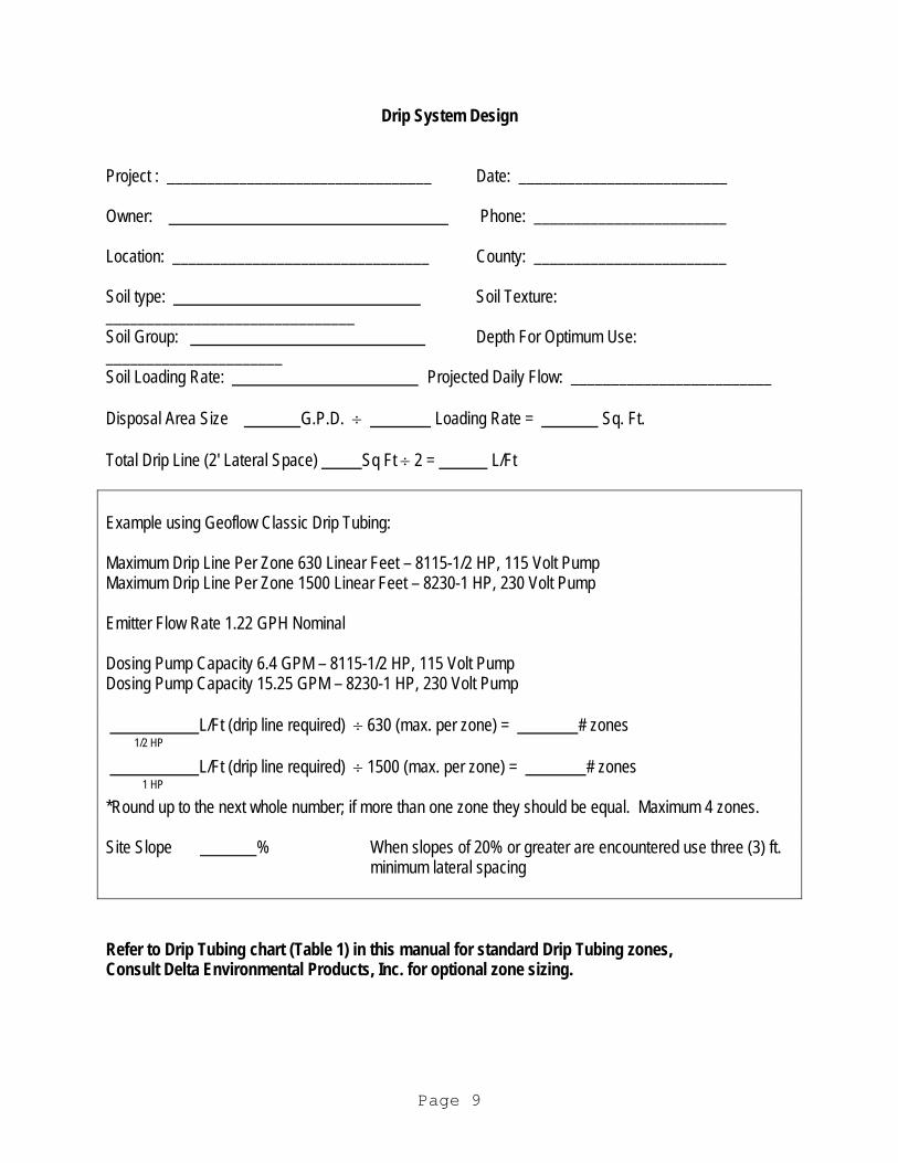
Drip System Design Project : _________________________________ Date: __________________________ Owner: Phone: ________________________ Location: ________________________________ County: ________________________ Soil type: Soil Texture: _______________________________ Soil Group: Depth For Optimum Use: ______________________ Soil Loading Rate: Projected Daily Flow: _________________________ Disposal Area Size G.P.D. ÷ Loading Rate = Sq. Ft. Total Drip Line (2' Lateral Space) Sq Ft ÷ 2 = L/Ft Example using Geoflow Classic Drip Tubing: Maximum Drip Line Per Zone 630 Linear Feet – 8115-1/2 HP, 115 Volt Pump Maximum Drip Line Per Zone 1500 Linear Feet – 8230-1 HP, 230 Volt Pump Emitter Flow Rate 1.22 GPH Nominal Dosing Pump Capacity 6.4 GPM – 8115-1/2 HP, 115 Volt Pump Dosing Pump Capacity 15.25 GPM – 8230-1 HP, 230 Volt Pump L/Ft (drip line required) ÷ 630 (max. per zone) = # zones 1/2 HP
L/Ft (drip line required) ÷ 1500 (max. per zone) = # zones 1 HP
*Round up to the next whole number; if more than one zone they should be equal. Maximum 4 zones. Site Slope % When slopes of 20% or greater are encountered use three (3) ft.
minimum lateral spacing Refer to Drip Tubing chart (Table 1) in this manual for standard Drip Tubing zones, Consult Delta Environmental Products, Inc. for optional zone sizing.
Page 9
Size of the Absorption Field The total size of the absorption area depends on the daily wastewater flow and the absorption capability of the soil.
1. Determine the estimated daily flow. The local health department will have guidelines for determining residential flows.
2. Determine the loading rate of the soil. The local health department will have guidelines for loading rate
per soil conditions. Qualified persons should conduct soil and site evaluations only. After evaluation of the soil, the hydraulic loading rate is established using the appropriate table (USDA soil classes or State approved tables).
3. Calculate the total area necessary for the absorption field with the following equation:
Area = Daily flow Soil Loading Rate
4. Determine the total length of the emitter line required in the absorption area. Spacing between laterals is normally 24 inches.
Total Absorption Area in Square Feet = Total Emitter Line Required.
Emitter Line Spacing
5. Determined the layout of the emitter line absorption field. When selecting the layout of the field, always place the emitters along the contours of the ground area, keeping the emitter line lateral runs as close to the same grade as possible. When running a continuous emitter line that requires a loop, make a connection to solid flex pipe to prevent the emitter line from kinking.
6. The Whitewater® 8115-1/2HP drip system is capable of zone sizes as indicated on Table 1. Using two
or more zones keeps the pump HP to a minimum. The Whitewater® 8230-1HP drip system is capable of zone sizes as indicated on Table 1. Using two or
more zones keeps the pump HP to a minimum. 7. The Whitewater® 8115-1/2 HP drip system utilizes a 1/2 HP dosing pump. The Whitewater®8 8230-1HP drip system utilizes a 1HP-dosing pump. 8. A pressure regulator is furnished and should be installed at the drip grid supply header at each zone.
The pressure regulator will provide proper pressure to the emitters. 9. The requirement of flushing the emitter lines, using the 8115-1/2HP, is important that proper velocities
be maintained through the entire system. The supply line from the filter unit to the emitter supply manifold should be as indicated on drawings to reduce the friction loss to a minimum and keep the velocity above 2 feet per second. Each zone must not have more than indicated on Table 1. This will ensure that each lateral will receive a minimum of 1.69 gallons per minute during a flush cycle. The return line is also an integral part of the system and must be sized for minimum friction loss and velocities above 2' feet per second.
Page 10
The requirement of flushing the emitter lines, using the 8230-1HP, is important that proper velocities be maintained through the entire system. The supply line from the filter unit to the emitter supply manifold should be as indicated on drawing to reduce the friction loss to a minimum and keep the velocity above 2 feet per second. Each zone must not have more than indicated on Table 1. This will ensure that each lateral will receive a minimum of 1.69 gallons per minute during a flush cycle. The return line is also an integral part of the system and must be sized for minimum friction loss and velocities above 2' per second.
10. A hydraulic zoning valve is typically furnished to automate the switching of zones. The simplicity of design and a minimum number of moving parts ensure ease of maintenance and a long service life. The four-outlet model has interchangeable cams for 2, 3, or 4 zone operation. It is important that each zone be of equal size. An absorption field with more than one zone will be dosed equally. The flushing cycle for multiple zones will be in sequential pump starts to ensure that each zone is flushed. Check valves are required to isolate each zone in a multiple zone system.
11. Solenoid valves can be used to automate the switching of zones. Contact factory for details.
The instantaneous water application rate of the system must not exceed the water absorption capacity of the soil. A determination of the instantaneous water absorption capacity of the soil is difficult; it varies with the water content of the soil. As the soil approaches saturation with water, the absorption rate reduces to an
Page 11
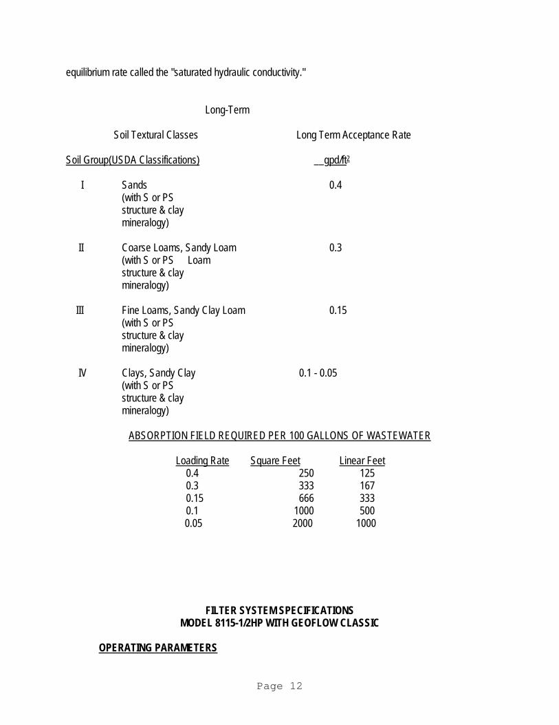
equilibrium rate called the "saturated hydraulic conductivity."
Long-Term Soil Textural Classes Long Term Acceptance Rate
Soil Group (USDA Classifications) __gpd/ft2 I Sands 0.4
(with S or PS structure & clay mineralogy)
II Coarse Loams, Sandy Loam 0.3
(with S or PS Loam structure & clay mineralogy)
III Fine Loams, Sandy Clay Loam 0.15
(with S or PS structure & clay mineralogy)
IV Clays, Sandy Clay 0.1 - 0.05
(with S or PS structure & clay mineralogy)
ABSORPTION FIELD REQUIRED PER 100 GALLONS OF WASTEWATER
Loading Rate Square Feet Linear Feet
0.4 250 125 0.3 333 167 0.15 666 333 0.1 1000 500 0.05 2000 1000
FILTER SYSTEM SPECIFICATIONS MODEL 8115-1/2HP WITH GEOFLOW CLASSIC OPERATING PARAMETERS
Page 12
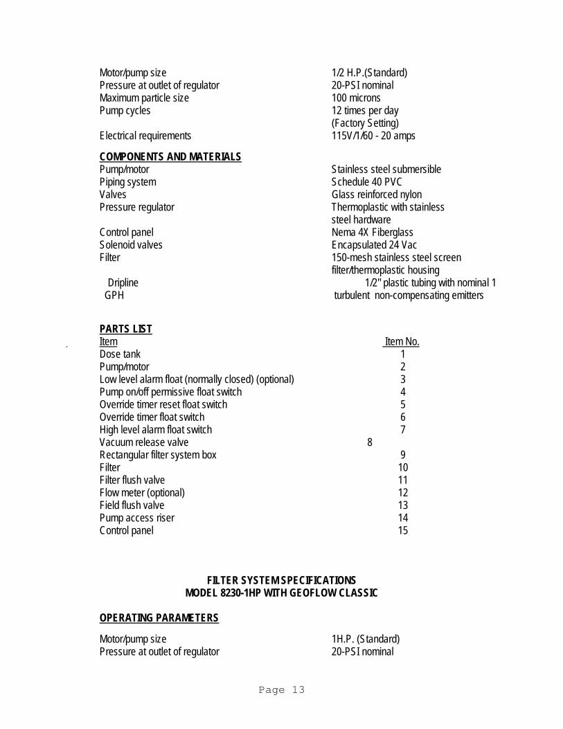
Motor/pump size 1/2 H.P.(Standard) Pressure at outlet of regulator 20-PSI nominal Maximum particle size 100 microns Pump cycles 12 times per day
(Factory Setting) Electrical requirements 115V/1/60 - 20 amps
COMPONENTS AND MATERIALS Pump/motor Stainless steel submersible Piping system Schedule 40 PVC Valves Glass reinforced nylon Pressure regulator Thermoplastic with stainless
steel hardware Control panel Nema 4X Fiberglass Solenoid valves Encapsulated 24 Vac Filter 150-mesh stainless steel screen
filter/thermoplastic housing Dripline 1/2" plastic tubing with nominal 1 GPH turbulent non-compensating emitters
PARTS LIST Item Item No. Dose tank 1 Pump/motor 2 Low level alarm float (normally closed) (optional) 3 Pump on/off permissive float switch 4 Override timer reset float switch 5 Override timer float switch 6 High level alarm float switch 7 Vacuum release valve 8 Rectangular filter system box 9 Filter 10 Filter flush valve 11 Flow meter (optional) 12 Field flush valve 13 Pump access riser 14 Control panel 15
FILTER SYSTEM SPECIFICATIONS MODEL 8230-1HP WITH GEOFLOW CLASSIC OPERATING PARAMETERS Motor/pump size 1H.P. (Standard) Pressure at outlet of regulator 20-PSI nominal
Page 13
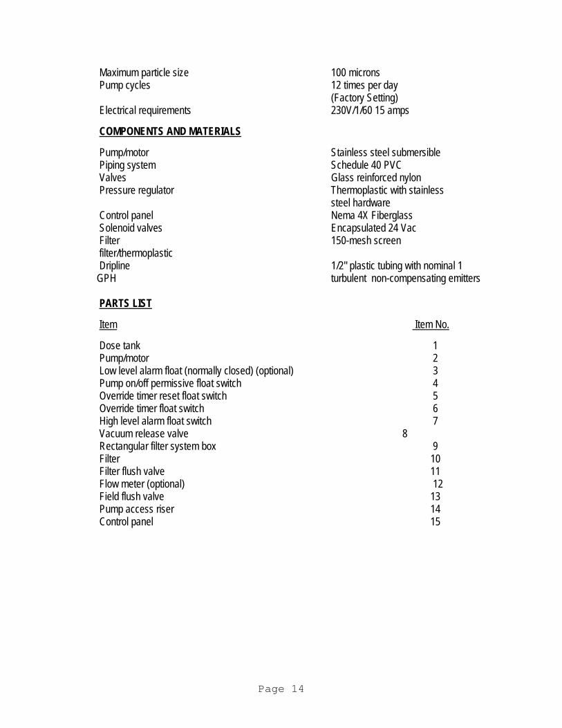
Maximum particle size 100 microns Pump cycles 12 times per day
(Factory Setting) Electrical requirements 230V/1/60 15 amps COMPONENTS AND MATERIALS Pump/motor Stainless steel submersible Piping system Schedule 40 PVC Valves Glass reinforced nylon Pressure regulator Thermoplastic with stainless
steel hardware Control panel Nema 4X Fiberglass Solenoid valves Encapsulated 24 Vac Filter 150-mesh screen filter/thermoplastic Dripline 1/2" plastic tubing with nominal 1 GPH turbulent non-compensating emitters PARTS LIST Item Item No. Dose tank 1 Pump/motor 2 Low level alarm float (normally closed) (optional) 3 Pump on/off permissive float switch 4 Override timer reset float switch 5 Override timer float switch 6 High level alarm float switch 7 Vacuum release valve 8 Rectangular filter system box 9 Filter 10 Filter flush valve 11 Flow meter (optional) 12 Field flush valve 13 Pump access riser 14 Control panel 15
Page 14
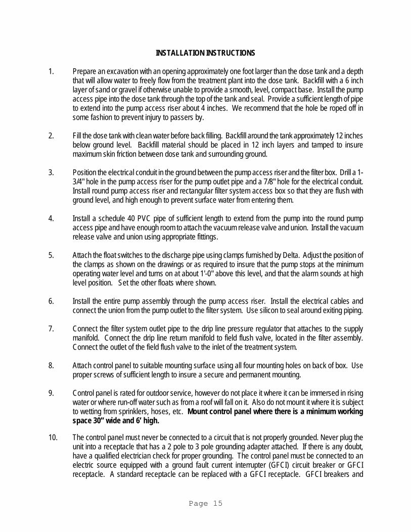
INSTALLATION INSTRUCTIONS 1. Prepare an excavation with an opening approximately one foot larger than the dose tank and a depth
that will allow water to freely flow from the treatment plant into the dose tank. Backfill with a 6 inch layer of sand or gravel if otherwise unable to provide a smooth, level, compact base. Install the pump access pipe into the dose tank through the top of the tank and seal. Provide a sufficient length of pipe to extend into the pump access riser about 4 inches. We recommend that the hole be roped off in some fashion to prevent injury to passers by.
2. Fill the dose tank with clean water before back filling. Backfill around the tank approximately 12 inches
below ground level. Backfill material should be placed in 12 inch layers and tamped to insure maximum skin friction between dose tank and surrounding ground.
3. Position the electrical conduit in the ground between the pump access riser and the filter box. Drill a 1-
3/4" hole in the pump access riser for the pump outlet pipe and a 7/8" hole for the electrical conduit. Install round pump access riser and rectangular filter system access box so that they are flush with ground level, and high enough to prevent surface water from entering them.
4. Install a schedule 40 PVC pipe of sufficient length to extend from the pump into the round pump
access pipe and have enough room to attach the vacuum release valve and union. Install the vacuum release valve and union using appropriate fittings.
5. Attach the float switches to the discharge pipe using clamps furnished by Delta. Adjust the position of
the clamps as shown on the drawings or as required to insure that the pump stops at the minimum operating water level and turns on at about 1'-0" above this level, and that the alarm sounds at high level position. Set the other floats where shown.
6. Install the entire pump assembly through the pump access riser. Install the electrical cables and
connect the union from the pump outlet to the filter system. Use silicon to seal around exiting piping. 7. Connect the filter system outlet pipe to the drip line pressure regulator that attaches to the supply
manifold. Connect the drip line return manifold to field flush valve, located in the filter assembly. Connect the outlet of the field flush valve to the inlet of the treatment system.
8. Attach control panel to suitable mounting surface using all four mounting holes on back of box. Use
proper screws of sufficient length to insure a secure and permanent mounting. 9. Control panel is rated for outdoor service, however do not place it where it can be immersed in rising
water or where run-off water such as from a roof will fall on it. Also do not mount it where it is subject to wetting from sprinklers, hoses, etc. Mount control panel where there is a minimum working space 30” wide and 6’ high.
10. The control panel must never be connected to a circuit that is not properly grounded. Never plug the
unit into a receptacle that has a 2 pole to 3 pole grounding adapter attached. If there is any doubt, have a qualified electrician check for proper grounding. The control panel must be connected to an electric source equipped with a ground fault current interrupter (GFCI) circuit breaker or GFCI receptacle. A standard receptacle can be replaced with a GFCI receptacle. GFCI breakers and
Page 15
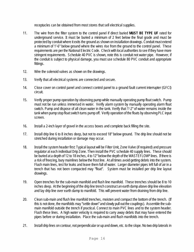
receptacles can be obtained from most stores that sell electrical supplies. 11. The wire from the filter system to the control panel if direct buried MUST BE TYPE UF rated for
underground service. It must be buried a minimum of 2 feet below the final grade and must be protected by conduit where it exits the ground as shown on installation drawings. Conduit must extend a minimum of 1'-6" below ground where the wires rise from the ground to the control panel. These requirements are per the National Electric Code. Check with local authorities to see if they have more stringent requirements. Schedule 40 PVC is shown, note this is conduit not water pipe. However, if the conduit is subject to physical damage, you must use schedule 80 PVC conduit and appropriate fittings.
12. Wire the solenoid valves as shown on the drawings. 13. Verify that all electrical systems are connected and secure. 14. Close cover on control panel and connect control panel to a ground fault current interrupter (GFCI)
circuit. 15. Verify proper pump operation by observing pump while manually operating pump float switch. Pump
must not be run unless immersed in water. Verify alarm system by manually operating alarm float switch. Pump and dispose of all clean water in the tank. Verify that 1'-2" of water remains inside the tank when pump stop float switch turns pump off. Verify operation of the floats by observing PLC input screen.
16. Install a 2-inch layer of gravel in the access boxes and complete back filling the site. 17. Install drip line 6 to 8 inches deep, but not to exceed 18" below ground. The drip line should not be
stretched during installation or damage may occur. 18. Install the system header first: Typical layout will be Filter Unit, Zone Valve (if required) and pressure
regulator at each individual Drip Zone. Then install the PVC schedule 40 supply lines. These should be buried at a depth of 12 to 18 inches, 4 to 12" below the depth of the WASTEFLOWR lines. If there is a risk of freezing, bury mainlines below the frost line. At all times avoid getting debris into the system. Flush main lines, test for leaks and leave them full of water. Larger diameter pipes left full of air in a trench that has not been compacted may "float". System must be installed per drip line layout drawings.
19. Open trenches for the sub-main manifold and flush line manifold. These trenches should be 8 to 10
inches deep. At the beginning of the drip line trench construct an earth damp above drip line elevation and lay drip line over earth damp to manifold. This will prevent water from draining from drip line.
20. Clean sub-main and flush line manifold trenches, moisten and compact the bottom of the trench. (If
this is not done, the manifolds may "settle down" and slowly pull out the couplings). Assemble the sub-main manifold outside the trench if practical. Connect to main PVC lines and to the system header. Flush these lines. A high water velocity is required to carry away debris that may have entered the pipes before or during installation. Place the sub-main and flush manifolds into the trench.
21. Install drip lines on contour, not perpendicular or up and down, etc. to the slope. No two drip laterals in
Page 16
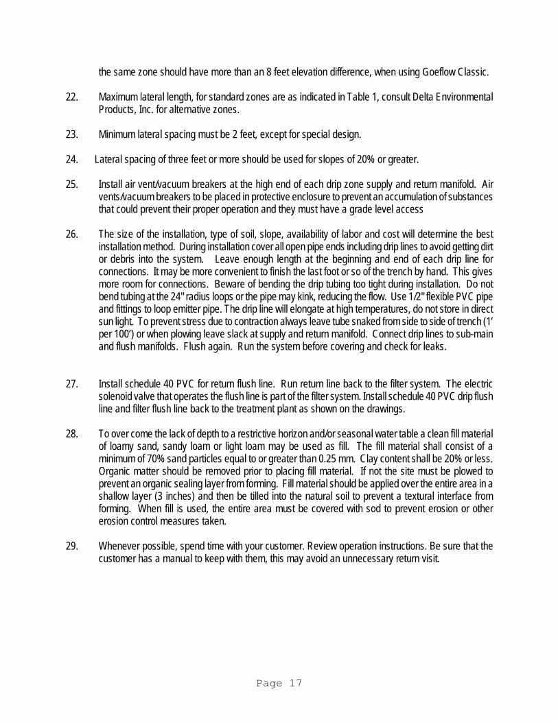
the same zone should have more than an 8 feet elevation difference, when using Goeflow Classic. 22. Maximum lateral length, for standard zones are as indicated in Table 1, consult Delta Environmental
Products, Inc. for alternative zones. 23. Minimum lateral spacing must be 2 feet, except for special design. 24. Lateral spacing of three feet or more should be used for slopes of 20% or greater. 25. Install air vent/vacuum breakers at the high end of each drip zone supply and return manifold. Air
vents/vacuum breakers to be placed in protective enclosure to prevent an accumulation of substances that could prevent their proper operation and they must have a grade level access
26. The size of the installation, type of soil, slope, availability of labor and cost will determine the best
installation method. During installation cover all open pipe ends including drip lines to avoid getting dirt or debris into the system. Leave enough length at the beginning and end of each drip line for connections. It may be more convenient to finish the last foot or so of the trench by hand. This gives more room for connections. Beware of bending the drip tubing too tight during installation. Do not bend tubing at the 24" radius loops or the pipe may kink, reducing the flow. Use 1/2" flexible PVC pipe and fittings to loop emitter pipe. The drip line will elongate at high temperatures, do not store in direct sun light. To prevent stress due to contraction always leave tube snaked from side to side of trench (1’ per 100’) or when plowing leave slack at supply and return manifold. Connect drip lines to sub-main and flush manifolds. Flush again. Run the system before covering and check for leaks.
27. Install schedule 40 PVC for return flush line. Run return line back to the filter system. The electric
solenoid valve that operates the flush line is part of the filter system. Install schedule 40 PVC drip flush line and filter flush line back to the treatment plant as shown on the drawings.
28. To over come the lack of depth to a restrictive horizon and/or seasonal water table a clean fill material
of loamy sand, sandy loam or light loam may be used as fill. The fill material shall consist of a minimum of 70% sand particles equal to or greater than 0.25 mm. Clay content shall be 20% or less. Organic matter should be removed prior to placing fill material. If not the site must be plowed to prevent an organic sealing layer from forming. Fill material should be applied over the entire area in a shallow layer (3 inches) and then be tilled into the natural soil to prevent a textural interface from forming. When fill is used, the entire area must be covered with sod to prevent erosion or other erosion control measures taken.
29. Whenever possible, spend time with your customer. Review operation instructions. Be sure that the
customer has a manual to keep with them, this may avoid an unnecessary return visit.
Page 17
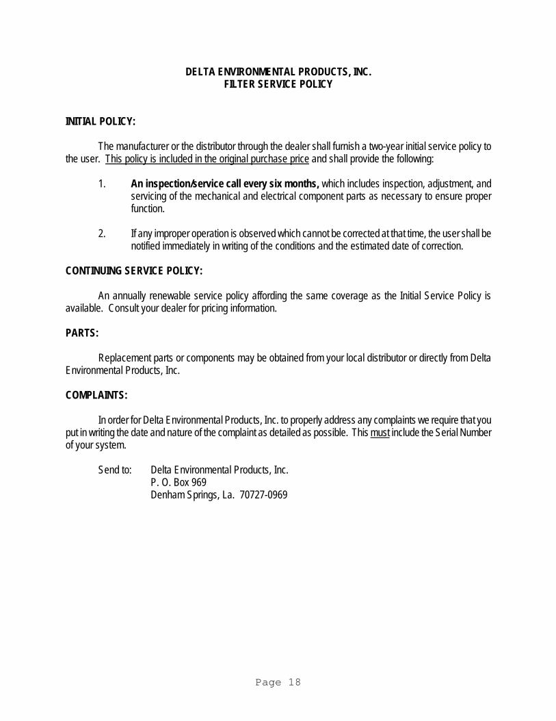
DELTA ENVIRONMENTAL PRODUCTS, INC. FILTER SERVICE POLICY INITIAL POLICY:
The manufacturer or the distributor through the dealer shall furnish a two-year initial service policy to the user. This policy is included in the original purchase price and shall provide the following:
1. An inspection/service call every six months, which includes inspection, adjustment, and servicing of the mechanical and electrical component parts as necessary to ensure proper function.
2. If any improper operation is observed which cannot be corrected at that time, the user shall be
notified immediately in writing of the conditions and the estimated date of correction. CONTINUING SERVICE POLICY:
An annually renewable service policy affording the same coverage as the Initial Service Policy is available. Consult your dealer for pricing information. PARTS:
Replacement parts or components may be obtained from your local distributor or directly from Delta Environmental Products, Inc. COMPLAINTS:
In order for Delta Environmental Products, Inc. to properly address any complaints we require that you put in writing the date and nature of the complaint as detailed as possible. This must include the Serial Number of your system.
Send to: Delta Environmental Products, Inc. P. O. Box 969 Denham Springs, La. 70727-0969
Page 18
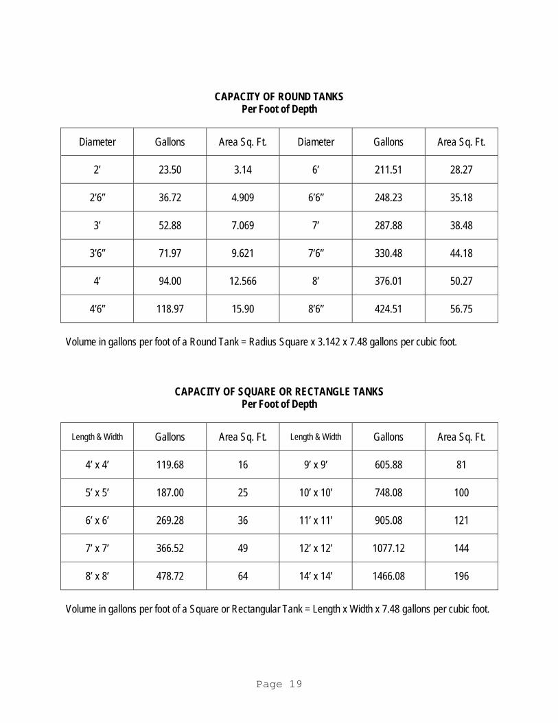
CAPACITY OF ROUND TANKS Per Foot of Depth
Diameter Gallons Area Sq. Ft. Diameter Gallons Area Sq. Ft.
2’ 23.50 3.14 6’ 211.51 28.27
2’6” 36.72 4.909 6’6” 248.23 35.18
3’ 52.88 7.069 7’ 287.88 38.48
3’6” 71.97 9.621 7’6” 330.48 44.18
4’ 94.00 12.566 8’ 376.01 50.27
4’6” 118.97 15.90 8’6” 424.51 56.75
Volume in gallons per foot of a Round Tank = Radius Square x 3.142 x 7.48 gallons per cubic foot.
CAPACITY OF SQUARE OR RECTANGLE TANKS Per Foot of Depth
Length & Width Gallons Area Sq. Ft. Length & Width Gallons Area Sq. Ft.
4’ x 4’ 119.68 16 9’ x 9’ 605.88 81
5’ x 5’ 187.00 25 10’ x 10’ 748.08 100
6’ x 6’ 269.28 36 11’ x 11’ 905.08 121
7’ x 7’ 366.52 49 12’ x 12’ 1077.12 144
8’ x 8’ 478.72 64 14’ x 14’ 1466.08 196
Volume in gallons per foot of a Square or Rectangular Tank = Length x Width x 7.48 gallons per cubic foot.
Page 19
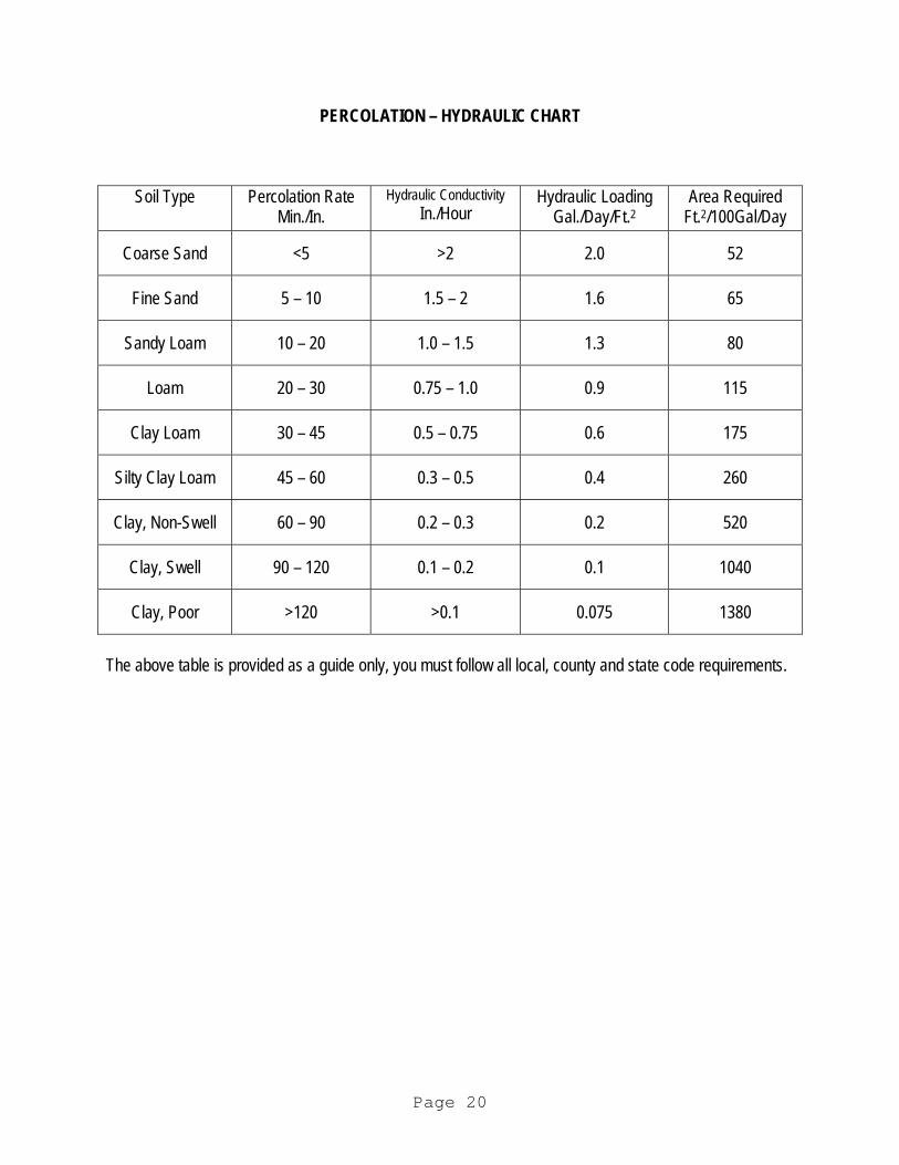
PERCOLATION – HYDRAULIC CHART
Soil Type Percolation Rate Min./In.
Hydraulic Conductivity In./Hour
Hydraulic Loading Gal./Day/Ft.2
Area Required Ft.2/100Gal/Day
Coarse Sand <5 >2 2.0 52
Fine Sand 5 – 10 1.5 – 2 1.6 65
Sandy Loam 10 – 20 1.0 – 1.5 1.3 80
Loam 20 – 30 0.75 – 1.0 0.9 115
Clay Loam 30 – 45 0.5 – 0.75 0.6 175
Silty Clay Loam 45 – 60 0.3 – 0.5 0.4 260
Clay, Non-Swell 60 – 90 0.2 – 0.3 0.2 520
Clay, Swell 90 – 120 0.1 – 0.2 0.1 1040
Clay, Poor >120 >0.1 0.075 1380
The above table is provided as a guide only, you must follow all local, county and state code requirements.
Page 20
LIMITED WARRANTY
Delta Environmental Products, Inc. warrants the parts supplied by Delta in each manual filter system for a period of two (2) years. All warranty questions shall be resolved through Delta Environmental Products, Inc. The warranty on the filter device is that the device is free from defects in material and workmanship from the date of installation. Some states do not allow limitations on how long an implied warranty lasts, so the above limitation may not apply. Sole obligation under this warranty is as follows: Delta Environmental Products, Inc. shall fulfill this warranty by repairing or exchanging any component part, F.O.B. factory that in Delta Environmental Products, Inc.'s judgment shows evidence of defects, provided said component part has been paid for and is returned through an authorized dealer, transportation prepaid. The warrantee must also specify the nature of the defect to the manufacturer.
The warranty does not cover filter processes/devices that have been flooded by external means, or that have been disassembled by unauthorized persons, improperly installed, subjected to external damage or damaged due to altered or improper wiring or parts not supplied by Delta.
This warranty applies only to the filter processes/devices and does not include any of the house wiring, plumbing, drainage, drip, sprinkling, or other disposal systems. Delta Environmental Products, Inc. is not responsible for any delay or damages caused by defective components or material, or for loss incurred because of interruption of service, or for any other special or consequential damages or incidental expenses arising from the manufacture, sale or use of this process/device.
Delta Environmental Products, Inc. reserves the right to revise, change or modify the construction and design of the process/device for household wastewater or any component part or parts thereof without incurring any obligation to make changes or modifications in previously sold equipment. Delta Environmental Products, Inc. also reserves the right, in making replacements of component parts under this warranty, to furnish a component part which, in its judgement is equivalent to the part replaced.
Under no circumstances will Delta Environmental Products, Inc. be responsible to the warrantee for any other direct or consequential damages, including but not limited to lost profits, lost income, labor charges, delays in production, and/or idle production, which damages are caused by a defect in material and/or workmanship in its parts. Some states do not allow the exclusion of limitation of incidental or consequential damages, so the above limitation or exclusion may not apply to you.
This warranty is expressly in lieu of any other express or implied warranty, excluding any warranty of merchantability or fitness and of any other obligation on the part of Delta Environmental Products, Inc.
This warranty gives you specific legal rights, and you may also have other rights, which vary, from state to state.
Page 21
GENERAL DESCRIPTION OF OPERATION
1. Upon power up at panel there is a 2 minute time delay before the pump starts. 2. After this time delay, the pump will start and run for a set period of time, then turn off for another
set period of time. 3. When the pump starts, the filter flush valve will open for a set period of time then close. 4. After a set number of pump starts, the field flush valve will open for a set period of time after the
pump starts and after the filter flush valve closes. 5. The field flush cycle will repeat itself on each subsequent pump cycle for the number of fields
connected to the system before resetting. 6. In a normal cycle, the field flush valve can be opened for a period of 60 seconds by momentarily
pushing the “Field Flush” toggle switch up then releasing it. This can be repeated for additional flushes.
7. At the end of each pumping cycle, after the pump shuts off, both the filter flush and field flush valves will open for a set period of time then close.
DESCRIPTION OF CONTROL FLOATS
1. Float FS1 is a wide angle float that when up, permits the pump to run and when down, keeps the pump from running and pumping dry. Note that by placing the HAND-OFF-AUTO switch in HAND position, will by-pass all floats and the pump will pump dry if held in that position long enough. The switch spring returns to OFF when released. After FS1 activates, there is a one minute delay before the pump will start if being called to run before the float activates.
2. Float FS2 is the override timer reset float and FS3 is the override timer float. These floats operate together. If the water level reaches FS3 while in an OFF period, the pump will start and the OFF period time will change to the setting in block B02. The run time remains as set in B01. The shorter OFF time will remain until the water level reaches FS2 after which the OFF time reverts back to the normal B01 setting.
3. Float FS4 is the high level alarm float. When the water level reaches this float, the high level alarm light illuminates continuously, and the audible alarm sounds continuously. The audible alarm can be silenced by the silence switch. When the high level water level recedes, the alarm will stop.
4. Float FS5 is an optional float that can be installed below FS1 that will cause an alarm at low water level. Low level alarm operation is identical to the high level alarm operation except the alarm light will flash and the audible alarm will sound intermittently.
5. Floats FS2, FS3, FS4 can be low current, normally open, mercury type. FS1 must be of the wide angle type. FS5 can be low current, normally closed, mercury type.
Page 22