Embed Size (px)
Citation preview
We reserve all rights in this document and in the information contained therein. Reproduction, use or disclosure to third parties without express authority is strictly forbidden. ABB
Prep. Kevin Behnisch Oct 2008 No. of sh.
Qual. EPS and SafeMove
45 Resp. dept. File 6904 ROP White Paper
SafeMove.doc
Document number Lang. Rev. ind. Sheet
ABB Robotics AB WHP –EPS-2006 en v.0.7 1 TEMPLATE: 6904 ROP WHITE PAPER SAFEMOVE.DOC; PRINTDATE: 13/08/2008 SAVEDATE: 11/10/2008 12:50:00 PM
White Paper
Safe collaboration with ABB robots
Electronic Position Switch and SafeMove
We reserve all rights in this document and in the information contained therein. Reproduction, use or disclosure to third parties without express authority is strictly forbidden. ABB
Document number Lang. Rev. ind. Sheet
ABB Robotics WHP-EPS-SafeMove en v.0.7 2
1 INTRODUCTION..........................................................................................................................................................4
1.1 ABOUT THIS DOCUMENT ...........................................................................................................................................4 2 ROBOT AUTOMATION AND PERSONAL SAFETY .............................................................................................5
2.1 REGULATIONS BY LAW .............................................................................................................................................5 2.2 CURRENT STANDARDS FOR ROBOTS..........................................................................................................................5 2.3 SAFETY CATEGORIES ................................................................................................................................................6 2.4 RISK ASSESSMENT ....................................................................................................................................................6 2.5 VALIDATION.............................................................................................................................................................7 2.6 TRAINING .................................................................................................................................................................7 2.7 ABB ROBOTS AND SAFETY .......................................................................................................................................7
3 ROBOT CELL DESIGN OF TODAY .........................................................................................................................8 3.1 TODAY’S GUARDING METHODS.................................................................................................................................8
3.1.1 Interlocked Barrier Guard..............................................................................................................................8 3.1.2 Fixed Barrier Guard.......................................................................................................................................8 3.1.3 Awareness Barrier Device ..............................................................................................................................8 3.1.4 Presence Sensing Devices...............................................................................................................................9 3.1.5 Audible and Visible Warning Systems ............................................................................................................9
3.2 END-EFFECTORS (END OF ARM TOOLING) REQUIREMENTS .....................................................................................9 3.3 MANIPULATOR POSITION INDICATION AND LIMITING................................................................................................9
3.3.1 Mechanical limits..........................................................................................................................................10 3.3.2 Position switches...........................................................................................................................................10 3.3.3 Limit Switch ..................................................................................................................................................10
3.4 CONTROLLER SAFETY-RELATED FUNCTIONS ..........................................................................................................11 3.4.1 Safe state.......................................................................................................................................................11 3.4.2 Stop categories..............................................................................................................................................11 3.4.3 ES Stop..........................................................................................................................................................12 3.4.4 Auto Stop.......................................................................................................................................................12 3.4.5 General Stop .................................................................................................................................................12 3.4.6 Motor-On Contacts .......................................................................................................................................12 3.4.7 Stopping distances ........................................................................................................................................13 3.4.8 Safe connections principle ............................................................................................................................14
4 EPS AND SAFEMOVE ...............................................................................................................................................15 4.1 ELECTRONIC POSITION SWITCH..............................................................................................................................16
4.1.1 Function description .....................................................................................................................................16 4.1.2 Customer Interface .......................................................................................................................................16
4.2 SAFEMOVE.............................................................................................................................................................17 4.2.1 Function description .....................................................................................................................................17 4.2.2 Customer Interface .......................................................................................................................................17
5 ENHANCED CELL DESIGN WITH EPS AND SAFEMOVE ...............................................................................18 5.1 INSTALLATION OF THE SYNCHRONIZATION SWITCH................................................................................................18
5.1.1 Program automatic synchronization.............................................................................................................18 5.2 USING SOFT SERVO, SOFTMOVE OR FORCE CONTROL..............................................................................................18 5.3 STOPPING DISTANCES .............................................................................................................................................18 5.4 BRAKE CHECK ........................................................................................................................................................19 5.5 SAFETY PROCEDURES .............................................................................................................................................19 5.6 CELL DESIGN ..........................................................................................................................................................20
5.6.1 Layout ...........................................................................................................................................................20 5.6.2 Limiting workspace.......................................................................................................................................20 5.6.3 Collaborating workspace..............................................................................................................................21 5.6.4 Collaborating workspace between robots and machinery equipment ..........................................................22 5.6.5 Connections to safety relays or safety PLC ..................................................................................................22
5.7 CELL DESIGN WITH EPS AND SAFEMOVE...............................................................................................................23 5.7.1 Invert of settings............................................................................................................................................23
We reserve all rights in this document and in the information contained therein. Reproduction, use or disclosure to third parties without express authority is strictly forbidden. ABB
Document number Lang. Rev. ind. Sheet
ABB Robotics WHP-EPS-SafeMove en v.0.7 3
5.7.2 Logical combination of axis..........................................................................................................................23 5.7.3 Supervision of wrist axis with EPS ...............................................................................................................24 5.7.4 Manual direct loading with SafeMove ..........................................................................................................25 5.7.5 Limiting workspace with SafeMove ..............................................................................................................25 5.7.6 Limiting tool orientation in critical processes ..............................................................................................26 5.7.7 Process supervision with Safe speed.............................................................................................................26 5.7.8 Safe speed for reducing brake and safety distances......................................................................................28 5.7.9 Combination of functions..............................................................................................................................28 5.7.10 Recovery from a safety supervision violation .............................................................................................28 5.7.11 Reducing brake distances ...........................................................................................................................29
6 COST COMPARISON ................................................................................................................................................29 6.1 EPS SAVINGS..........................................................................................................................................................29 6.2 SAFEMOVE SAVINGS ..............................................................................................................................................30
7 CONCLUSIONS ..........................................................................................................................................................31
8 APPENDIX A: EPS EXAMPLES ..............................................................................................................................32 8.1 EPS: MONITOR AXIS RANGES.................................................................................................................................32 8.2 DIRECT CONNECTION OF EPS TO THE AUTO STOP CIRCUIT OF THE PANEL BOARD...................................................33
9 APPENDIX B: SAFEMOVE EXAMPLES ...............................................................................................................34 9.1 MONITOR TOOLZONES AND SAFETOOLZONES.......................................................................................................34 9.2 SAFE STAND STILL/DIRECT LOADING OF A ROBOT .................................................................................................34
9.2.1 Monitor safe stand still .................................................................................................................................35 9.2.2 Safe stand still supervision............................................................................................................................35
9.3 SAFE AXIS RANGES WITH TRACK MOTIONS ............................................................................................................36 9.4 SAFE TOOL SUPERVISION DURING WATER JET CUTTING WITH SAFE-ORIENT SUPERVISION......................................36
10 APPENDIX C: EIO DEFINITION FOR EPS.........................................................................................................37
11 APPENDIX D: RAPID EXAMPLES FOR EPS AND SAFEMOVE ....................................................................38 11.1 CODE FOR SYNCHRONIZATION ..............................................................................................................................38 11.2 CODE FOR DETECTION THAT THE PRE-WARNING OF SYNCHRONIZATION HAS EXPIRED..........................................39 11.3 AUTOMATICALLY COPYING CONFIGURATION FILES TO HOME DIRECTORY..........................................................40 11.4 AUTOMATIC SPEED REDUCTION ............................................................................................................................41 11.5 AUTOMATIC SPACE DEFINITION ............................................................................................................................43
We reserve all rights in this document and in the information contained therein. Reproduction, use or disclosure to third parties without express authority is strictly forbidden. ABB
Document number Lang. Rev. ind. Sheet
ABB Robotics WHP-EPS-SafeMove en v.0.7 4
1 Introduction
1.1 About this document
This document should help the ABB robot system integrator to use the new safety possibilities with EPS (Electronic position switch) and SafeMove.
The new SafeMove and EPS products are in line with the new robotic standard ISO 10218-1.
The new ISO 10218-1 standard and the upcoming ISO 10218-2 will replace the European standard EN 775 and the US standard ANSI RIA 1999.
In the new ISO-Standard 10218-1 (Robots for industrial environments Safety requirements —Part 1 Robot) in Chapter 5.12 Axis limiting, the new possibility of using soft rated limits is described. ABB’s EPS and SafeMove solutions will take advantage of this to offer the Integrator new features for an enhanced application setup for human robot collaboration.
This document will help the robot user to use the new features and speed up the integration in the whole application.
This document does not replace the official and existing standards in the world; rather, it should be regarded as a guide to integrating the new ABB safety products in the application.
We reserve all rights in this document and in the information contained therein. Reproduction, use or disclosure to third parties without express authority is strictly forbidden. ABB
Document number Lang. Rev. ind. Sheet
ABB Robotics WHP-EPS-SafeMove en v.0.7 5
2 Robot Automation and personal safety
2.1 Regulations by law In general, the machine builder has to follow general Directives that are related to each country or union. The purpose of these Directives is to form a base for all kinds of machines on the market and ensure that the design of a machine is such that it prevents possible hazards.
World–wide, there are different Directives:
European countries:
The Machinery Directive 98/37/EC provides the regulatory basis for the harmonization of the essential health and safety requirements for machinery at the European Union level. Essentially performing a dual function, the Directive not only promotes the free movement of machinery within the Single Market, but also guarantees a high level of protection to EU workers and citizens. Being a "New Approach" Directive, it promotes harmonization through a combination of mandatory health and safety requirements and voluntary harmonized standards. Such Directives apply only to products that are intended to be placed (or put into service) in the EU market for the first time.
Machinery is described in the Directive as "an assembly of linked parts or components, at least one of which moves, with the appropriate actuators, control and power circuits, etc., joined together for a specific application, in particular for the processing, treatment, moving or packaging of a material". The manufacturer is responsible for verifying whether a particular product falls within the scope of the Machinery Directive.
A revised Machinery Directive - Directive 2006/42/EC of the European Parliament and of the Council of 17 May 2006 on machinery, and amending Directive 95/16/EC (recast) - was published on 9th June 2006. It will be applicable from 29th December 2009; until that date, the current Machinery Directive 98/37/EC continues to apply.
North America
Very different regulations exist in North America, and vary from county to county. But, basically, it is stated that the employer is responsible for the safety of the job. In case of injury, the manufacturer of the product can be held responsible because of product liability.
Asia:
In Japan there is a different situation than in the EU or North America There the employer takes the responsibility for a safe work environment. There is no legal requirement to use the engineering standards; furthermore, the trained operator takes care of his own personal safety. The standards in Japan are regulated by the JIS (Japanese Industrial Standards) organization. This organization abuts the European standards.
2.2 Current standards for robots There are different types of safety regulations that apply to robot systems.
The ABB product manuals for the controller and the manipulator respectively contain the necessary information regarding which regulation has been fulfilled by the shipment of the robot. Please note that the robot controller and the manipulator do not constitute a complete machine; thus only a declaration by the manufacturer is necessary. After adding a tool and creating an application, the robot system becomes a machine and a declaration of confirmation is necessary.
Today, three different standards for robot safety are used around the globe: The EN 775 in Europe, the ANSI RIA from 15.06.1999 for the US market, and the Z434-03 for Canada (from the Canadian Standard Association, CSA).
We reserve all rights in this document and in the information contained therein. Reproduction, use or disclosure to third parties without express authority is strictly forbidden. ABB
Document number Lang. Rev. ind. Sheet
ABB Robotics WHP-EPS-SafeMove en v.0.7 6
A new ISO 10218 Standard will replace the EN 775. In the United States, the ISO 10218 and the ANSI RIA 15.06.1999 are both valid - if something is not covered by the ISO Standard, ANSI RIA 15.06.1999 then applies.
These standards are voluntary, but they help the integrator and the robot supplier with practical advice on how a setup should be done in a safe way. For instance, by fulfilling the requirements of ISO 10218, an installation will also fulfil the Machinery Directive.
In other countries, only local bodies exist for the inspection of machine safety and the integration of machines. There, standards such as the ANSI should be used as a guideline for the machine integration.
In addition, it is possible for an integrator to certify his application through a notified body like TÜV, UL or the local industrial injuries corporation (in Germany called “Berufsgenossenschaft”).
The requirement for robot safety is at the category 3 level as described in EN 954-1:1999 (EU harmonization of ISO 13849-1:1999), which is the current standard for the safety of machinery. Category 3 is normally achieved through redundant circuits, like dual channels. In the new standard EN ISO 13849-1:2006, which will replace the EN 954 in 2009, robots shall instead comply with performance level (PL) “d”, which is a superset of category 3, i.e. robots still have to reach category 3 in order to fulfill PL d.
2.3 Safety categories After a great deal of debate, both in the media and in committee meeting rooms, voting has been in favour of superseding EN 954-1 with EN (ISO) 13849-1, 'Safety of machinery, Safety-related parts of control systems, Part 1: General principles for design' (the UK, USA and Japan were the only nations to vote against). The new standard was issued in 2006; but there is a three-year transition period during which EN 954-1 can still be used
Although much criticism was expressed regarding the 'risk graph' used in EN 954-1 to select safety categories, and the standard's replacement was seen in some quarters as a good opportunity to dispense with it, a similar type of graph has been used in EN (ISO) 13849-1 for the selection of Performance Levels (which are similar in concept to the safety categories in EN 954-1). Following on from this graph, further guidance is included in the new standard to assist with the system design, meaning that the math required is, in many cases, minimal (which is in stark contrast to EN 62061, the standard to be used for the design of software-programmable safety-related electrical control systems). In general terms, EN (ISO) 13849-1 takes a four-stage approach to the design of safety-related control systems: 1. Perform a risk assessment. 2. Allocate the safety measure (Performance Level (PL)) for the identified risks. 3. Devise a system architecture that is suitable for the Performance Level. 4. Validate the design to check that it meets the requirements of the initial risk assessment.
2.4 Risk assessment The risk assessment process begins at the integration of a robot system, with the specification of its designed purpose (intended use) and the limits described in ISO 12100-1 and ISO 11161. The risk assessment is a series of logical steps to enable the analysis and evaluation of the risk associated with the machinery in a systematic way. The risk assessment is followed, whenever necessary, by risk reduction. When this process is repeated, it gives the iterative process for eliminating hazards as far as practicable and for reducing risks by implementing protective devices (Taken from ISO DIS 14121-1 9-2005). A robot system design concept should include the following elements as a minimum:
• Limits of the Robot System
We reserve all rights in this document and in the information contained therein. Reproduction, use or disclosure to third parties without express authority is strictly forbidden. ABB
Document number Lang. Rev. ind. Sheet
ABB Robotics WHP-EPS-SafeMove en v.0.7 7
• Task identification
• User considerations.
2.5 Validation In terms of creating complex cell setups where human and machines are interacting, validating all safety configurations in your setup is a must. This can be done by the system integrator, end customer or official associations and/or licensed organizations. The scope is a final check to see that all hazards and risks are considered.
2.6 Training Particularly regarding the use of safety equipment, the user should be well-trained. He must be aware of the possible hazards and should have an overview of the entire application. Robotic programmers and engineers should be aware that they can cause a hazard when programming and configure a robot system in the wrong way. Therefore, he should be familiar with the safety information on the manipulator and the control system.
2.7 ABB robots and safety All ABB robots comply with all relevant standards and safety regulations, which is documented in a “declaration by manufacturer”. This means that the safety-related parts of the robots and controllers fulfill EN ISO 10218-1:2006, Safety requirements for robots, and comply with category 3 as described in EN 954-1.
ABB robots can be equipped with a special safety controller, either EPS (Electronic Position Switch) or SafeMove, as described further on in this document. The compliance with the above-mentioned standards is, of course, also valid with these options.
In addition, and for additional safety, EPS and SafeMove fulfill performance level and category 3 of the new EN ISO 13849-1, with a so-called design concept approval for the highest performance level, PL e. This compliance on the part of EPS and SafeMove has been certified by certified bodies (Inspecta, BGIA and UL) after careful inspection of all the safety-related parts.
Note that the overall safety level of the controller equipped with EPS or SafeMove remains at category 3 (certification for PL d is ongoing and planned to be in place before ISO 13849-1 becomes mandatory in 2009).
We reserve all rights in this document and in the information contained therein. Reproduction, use or disclosure to third parties without express authority is strictly forbidden. ABB
Document number Lang. Rev. ind. Sheet
ABB Robotics WHP-EPS-SafeMove en v.0.7 8
3 Robot cell design of today
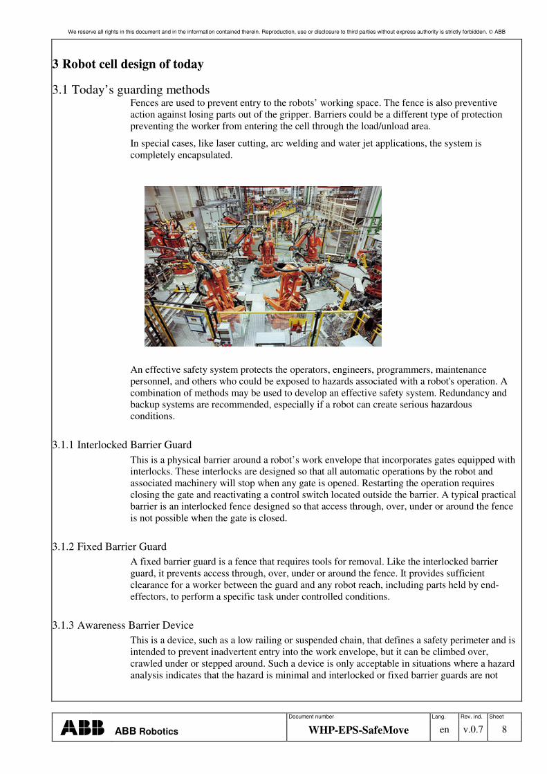
3.1 Today’s guarding methods Fences are used to prevent entry to the robots’ working space. The fence is also preventive action against losing parts out of the gripper. Barriers could be a different type of protection preventing the worker from entering the cell through the load/unload area.
In special cases, like laser cutting, arc welding and water jet applications, the system is completely encapsulated.
An effective safety system protects the operators, engineers, programmers, maintenance personnel, and others who could be exposed to hazards associated with a robot's operation. A combination of methods may be used to develop an effective safety system. Redundancy and backup systems are recommended, especially if a robot can create serious hazardous conditions.
3.1.1 Interlocked Barrier Guard This is a physical barrier around a robot’s work envelope that incorporates gates equipped with interlocks. These interlocks are designed so that all automatic operations by the robot and associated machinery will stop when any gate is opened. Restarting the operation requires closing the gate and reactivating a control switch located outside the barrier. A typical practical barrier is an interlocked fence designed so that access through, over, under or around the fence is not possible when the gate is closed.
3.1.2 Fixed Barrier Guard A fixed barrier guard is a fence that requires tools for removal. Like the interlocked barrier guard, it prevents access through, over, under or around the fence. It provides sufficient clearance for a worker between the guard and any robot reach, including parts held by end-effectors, to perform a specific task under controlled conditions.
3.1.3 Awareness Barrier Device This is a device, such as a low railing or suspended chain, that defines a safety perimeter and is intended to prevent inadvertent entry into the work envelope, but it can be climbed over, crawled under or stepped around. Such a device is only acceptable in situations where a hazard analysis indicates that the hazard is minimal and interlocked or fixed barrier guards are not
We reserve all rights in this document and in the information contained therein. Reproduction, use or disclosure to third parties without express authority is strictly forbidden. ABB
Document number Lang. Rev. ind. Sheet
ABB Robotics WHP-EPS-SafeMove en v.0.7 9
feasible. Interlocked or fixed barrier guards provide the positive protection needed to prevent worker exposure to robotic systems hazards.
3.1.4 Presence Sensing Devices The presence detectors that are most commonly used in robotics safety are pressure mats and light curtains. Floor mats (pressure-sensitive mats), light curtains (similar to arrays of photocells) and laser scanners can be used to detect a person stepping into a hazardous area near a robot. Effective presence sensing devices stop all motion in the robot if any part of a worker's body enters the protected zone. They are also designed to be fail-safe so that the occurrence of a failure within the device will leave it unaffected or convert it into a mode in which its failed state would not result in an accident. In some cases this means deactivation of the robot. Factors that are considered in the selection of such devices include the spatial limitations of the field, the environmental conditions affecting the reliability of the field, and the sensing field interference due to robot operation.
3.1.5 Audible and Visible Warning Systems Audible and visible warning systems are not acceptable safeguarding methods but may be used to enhance the effectiveness of positive safeguards. The purposes of audible and visible signals need to be easily recognizable.
3.2 End-Effectors (End of Arm Tooling) Requirements End effectors shall be designed and constructed so that:
A loss of or change in the energy supply (e.g., electrical, hydraulic, pneumatic, vacuum supply) shall not cause the tool to release the load or result in a hazardous condition. The tool design shall fit the load diagram of the selected robot system. Be aware that in addition to the tool, mass, inertia and centre of gravity are important figures of the robot system. One big risk results from using detachable tools or, e.g., tool changer. If the release could result in a hazardous situation, the release of detachable tools shall only occur in designated locations or under specific, controlled conditions.
Furthermore, risks from tools can also be noise, laser beams, or high pressure water jet cutting.
3.3 Manipulator position indication and limiting In every use of a robot system there is a connection to the external safety devices. These connections can be to control the robot system from external devices like a PLC. But in every case a robot system will have a connection to external safety devices like door locks, light barriers or safety scanners to ensure that the robot can be stopped in a safe way.
The robot itself has different possibilities to safely limit the working area or to indicate the area in which the robot can safely move.
Traditionally, there were mainly mechanical solutions to provide these features. With EPS and SafeMove (see Chapter 4) it is now possible to use completely electronic solutions.
We reserve all rights in this document and in the information contained therein. Reproduction, use or disclosure to third parties without express authority is strictly forbidden. ABB
Document number Lang. Rev. ind. Sheet
ABB Robotics WHP-EPS-SafeMove en v.0.7 10
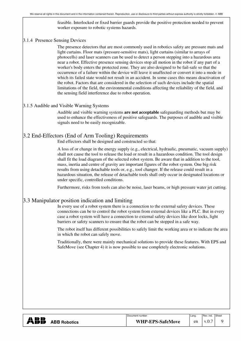
3.3.1 Mechanical limits Mechanical limits are used to reduce the working area for the robot. Historically, the fences around the robot system have been outside the robot’s maximum workspace. Due to the complex cell layout design, it was not possible to mechanically reduce the working area of the manipulator in most cases. In particular, the bending backwards kinematics are extremely difficult to limit to the working range of axis 2 and 3 because the robot’s working range is needed for the front area, but it should be limited in the area behind it.
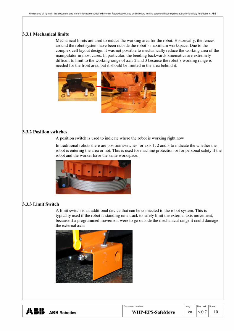
3.3.2 Position switches A position switch is used to indicate where the robot is working right now
In traditional robots there are position switches for axis 1, 2 and 3 to indicate the whether the robot is entering the area or not. This is used for machine protection or for personal safety if the robot and the worker have the same workspace.
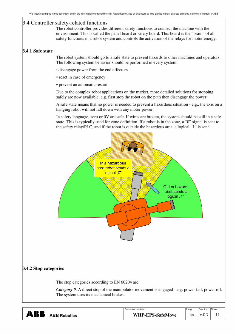
3.3.3 Limit Switch A limit switch is an additional device that can be connected to the robot system. This is typically used if the robot is standing on a track to safely limit the external axis movement, because if a programmed movement were to go outside the mechanical range it could damage the external axis.
We reserve all rights in this document and in the information contained therein. Reproduction, use or disclosure to third parties without express authority is strictly forbidden. ABB
Document number Lang. Rev. ind. Sheet
ABB Robotics WHP-EPS-SafeMove en v.0.7 11
3.4 Controller safety-related functions The robot controller provides different safety functions to connect the machine with the environment. This is called the panel board or safety board. This board is the “brain” of all safety functions in a robot system and controls the activation of the relays for motor energy.
3.4.1 Safe state The robot system should go to a safe state to prevent hazards to other machines and operators. The following system behavior should be performed in every system:
• disengage power from the end effectors
• react in case of emergency
• prevent an automatic restart.
Due to the complex robot applications on the market, more detailed solutions for stopping safely are now available, e.g. first stop the robot on the path then disengage the power.
A safe state means that no power is needed to prevent a hazardous situation - e.g., the axis on a hanging robot will not fall down with any motor power.
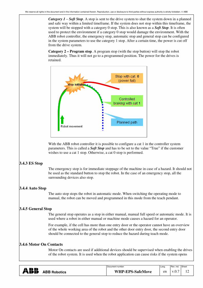
In safety language, zero or 0V are safe. If wires are broken, the system should be still in a safe state. This is typically used for zone definition. If a robot is in the zone, a “0” signal is sent to the safety relay/PLC, and if the robot is outside the hazardous area, a logical “1“ is sent.
3.4.2 Stop categories
The stop categories according to EN 60204 are:
Category 0. A direct stop of the manipulator movement is engaged - e.g. power fail, power off. The system uses its mechanical brakes.
We reserve all rights in this document and in the information contained therein. Reproduction, use or disclosure to third parties without express authority is strictly forbidden. ABB
Document number Lang. Rev. ind. Sheet
ABB Robotics WHP-EPS-SafeMove en v.0.7 12
Category 1 – Soft Stop. A stop is sent to the drive system to shut the system down in a planned and safe way within a limited timeframe. If the system does not stop within this timeframe, the system will be stopped with a category 0 stop. This is also known as a Soft Stop. It is often used to protect the environment if a category 0 stop would damage the environment. With the ABB robot controller, the emergency stop, automatic stop and general stop can be configured in the system parameters to use the category 1 stop. After a certain time, the power is cut off from the drive system.
Category 2 – Program stop. A program stop (with the stop button) will stop the robot immediately. Thus it will not go to a programmed position. The power for the drives is retained.
With the ABB robot controller it is possible to configure a cat 1 in the controller system parameters. This is called a Soft Stop and has to be set to the value “True” if the customer wishes to use a cat 1 stop. Otherwise, a cat 0 stop is performed.
3.4.3 ES Stop The emergency stop is for immediate stoppage of the machine in case of a hazard. It should not be used as the standard button to stop the robot. In the case of an emergency stop, all the surrounding devices also stop.
3.4.4 Auto Stop The auto stop stops the robot in automatic mode. When switching the operating mode to manual, the robot can be moved and programmed in this mode from the teach pendant.
3.4.5 General Stop The general stop operates as a stop in either manual, manual full speed or automatic mode. It is used where a robot in either manual or machine mode causes a hazard for an operator.
For example, if the cell has more than one entry door or the operator cannot have an overview of the whole working area of the robot and the other door entry door, the second entry door should be connected to the general stop to reduce the hazard during teach mode.
3.4.6 Motor On Contacts Motor On contacts are used if additional devices should be supervised when enabling the drives of the robot system. It is used when the robot application can cause risks if the system opens
We reserve all rights in this document and in the information contained therein. Reproduction, use or disclosure to third parties without express authority is strictly forbidden. ABB
Document number Lang. Rev. ind. Sheet
ABB Robotics WHP-EPS-SafeMove en v.0.7 13
the drive contacts in an emergency. A typical application is, when the robot uses a laser tool, to enable only the laser power source if the robot controller motors are enabled.
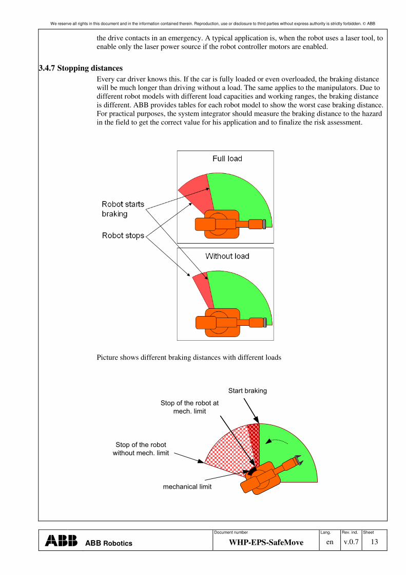
3.4.7 Stopping distances Every car driver knows this. If the car is fully loaded or even overloaded, the braking distance will be much longer than driving without a load. The same applies to the manipulators. Due to different robot models with different load capacities and working ranges, the braking distance is different. ABB provides tables for each robot model to show the worst case braking distance. For practical purposes, the system integrator should measure the braking distance to the hazard in the field to get the correct value for his application and to finalize the risk assessment.
Picture shows different braking distances with different loads
��������������
��� ������
��������� ��
���������
��������� �
��������������
We reserve all rights in this document and in the information contained therein. Reproduction, use or disclosure to third parties without express authority is strictly forbidden. ABB
Document number Lang. Rev. ind. Sheet
ABB Robotics WHP-EPS-SafeMove en v.0.7 14
Picture shows the braking distance with and without mechanical limit.
3.4.8 Safe connections principle Dual channel safety connections can be done in two different ways:
Equivalent sensor:
An equivalent sensor sends the same voltage level all the time. A short glitch, typically <10ms, is used to detect whether the outputs are connected together.
When an equivalent input is used, the power supply/output for the end effectors will send the glitch.
A typical example of an equivalent sensor is a light curtain or laser scanner.
Antivalent sensor:
An antivalent sensor means that it has a 24 V channel and 0 V channel. A short-circuit is detected if these channels are connected together. An example of this type is a door opener or a safety switch.
Glitch output
This to detect whether a short-circuit between the two lines will result in a fault not being detected. It can be directly sent by an active sensor or a safety PLC will provide a supply voltage with glitch behavior.
We reserve all rights in this document and in the information contained therein. Reproduction, use or disclosure to third parties without express authority is strictly forbidden. ABB
Document number Lang. Rev. ind. Sheet
ABB Robotics WHP-EPS-SafeMove en v.0.7 15
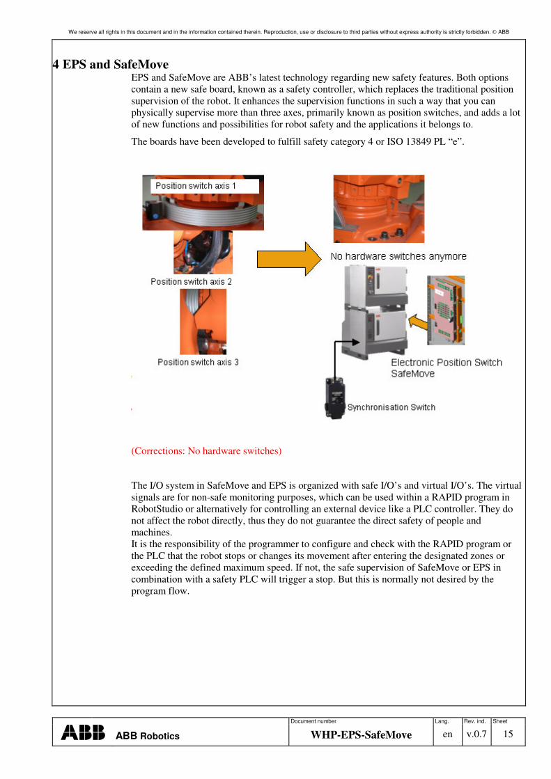
4 EPS and SafeMove EPS and SafeMove are ABB’s latest technology regarding new safety features. Both options contain a new safe board, known as a safety controller, which replaces the traditional position supervision of the robot. It enhances the supervision functions in such a way that you can physically supervise more than three axes, primarily known as position switches, and adds a lot of new functions and possibilities for robot safety and the applications it belongs to.
The boards have been developed to fulfill safety category 4 or ISO 13849 PL “e”.
(Corrections: No hardware switches)
The I/O system in SafeMove and EPS is organized with safe I/O’s and virtual I/O’s. The virtual signals are for non-safe monitoring purposes, which can be used within a RAPID program in RobotStudio or alternatively for controlling an external device like a PLC controller. They do not affect the robot directly, thus they do not guarantee the direct safety of people and machines. It is the responsibility of the programmer to configure and check with the RAPID program or the PLC that the robot stops or changes its movement after entering the designated zones or exceeding the defined maximum speed. If not, the safe supervision of SafeMove or EPS in combination with a safety PLC will trigger a stop. But this is normally not desired by the program flow.
We reserve all rights in this document and in the information contained therein. Reproduction, use or disclosure to third parties without express authority is strictly forbidden. ABB
Document number Lang. Rev. ind. Sheet
ABB Robotics WHP-EPS-SafeMove en v.0.7 16
4.1 Electronic Position Switch
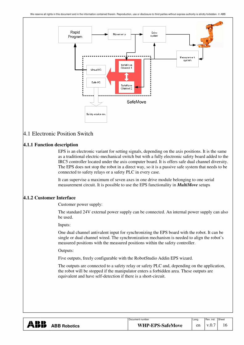
4.1.1 Function description EPS is an electronic variant for setting signals, depending on the axis positions. It is the same as a traditional electric-mechanical switch but with a fully electronic safety board added to the IRC5 controller located under the axis computer board. It is offers safe dual channel diversity. The EPS does not stop the robot in a direct way, so it is a passive safe system that needs to be connected to safety relays or a safety PLC in every case.
It can supervise a maximum of seven axes in one drive module belonging to one serial measurement circuit. It is possible to use the EPS functionality in MultiMove setups
4.1.2 Customer Interface Customer power supply:
The standard 24V external power supply can be connected. An internal power supply can also be used.
Inputs:
One dual channel antivalent input for synchronizing the EPS board with the robot. It can be single or dual channel wired. The synchronization mechanism is needed to align the robot’s measured positions with the measured positions within the safety controller.
Outputs:
Five outputs, freely configurable with the RobotStudio Addin EPS wizard.
The outputs are connected to a safety relay or safety PLC and, depending on the application, the robot will be stopped if the manipulator enters a forbidden area. These outputs are equivalent and have self-detection if there is a short-circuit.
We reserve all rights in this document and in the information contained therein. Reproduction, use or disclosure to third parties without express authority is strictly forbidden. ABB
Document number Lang. Rev. ind. Sheet
ABB Robotics WHP-EPS-SafeMove en v.0.7 17
4.2 SafeMove
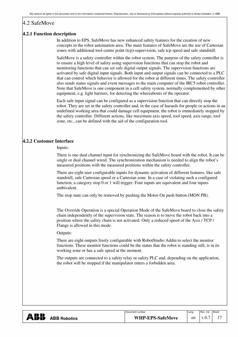
4.2.1 Function description In addition to EPS, SafeMove has new enhanced safety features for the creation of new concepts in the robot automation area. The main features of SafeMove are the use of Cartesian zones with additional tool centre point (tcp)-supervision, safe tcp speed and safe standstill.
SafeMove is a safety controller within the robot system. The purpose of the safety controller is to ensure a high level of safety using supervision functions that can stop the robot and monitoring functions that can set safe digital output signals. The supervision functions are activated by safe digital input signals. Both input and output signals can be connected to a PLC that can control which behavior is allowed for the robot at different times. The safety controller also sends status signals and event messages to the main computer of the IRC5 robot controller. Note that SafeMove is one component in a cell safety system, normally complemented by other equipment, e.g. light barriers, for detecting the whereabouts of the operator.
Each safe input signal can be configured as a supervision function that can directly stop the robot. They are set in the safety controller and, in the case of hazards for people or actions in an undefined working area that could damage cell equipment, the robot is immediately stopped by the safety controller. Different actions, like maximum axis speed, tool speed, axis range, tool zone, etc., can be defined with the aid of the configuration tool.
4.2.2 Customer Interface Inputs:
There is one dual channel input for synchronizing the SafeMove board with the robot. It can be single or dual channel wired. The synchronization mechanism is needed to align the robot’s measured positions with the measured positions within the safety controller.
There are eight user configurable inputs for dynamic activation of different features, like safe standstill, safe Cartesian speed or a Cartesian zone. In a case of violating such a configured function, a category stop 0 or 1 will trigger. Four inputs are equivalent and four inputs ambivalent.
The stop state can only be removed by pushing the Motor-On push button (MON PB).
The Override Operation is a special Operation Mode of the SafeMove board to close the safety chain independently of the supervision state. The reason is to move the robot back into a position where the safety chain is not activated. Only a reduced speed of the Axis / TCP / Flange is allowed in this mode.
Outputs:
There are eight outputs freely configurable with RobotStudio Addin to select the monitor functions. These monitor functions could be the status that the robot is standing still, is in its working zone or has a safe speed at the moment.
The outputs are connected to a safety relay or safety PLC and, depending on the application, the robot will be stopped if the manipulator enters a forbidden area.
We reserve all rights in this document and in the information contained therein. Reproduction, use or disclosure to third parties without express authority is strictly forbidden. ABB
Prep. Kevin Behnisch Oct 2008 No. of sh.
Qual. EPS and SafeMove
45 Resp. dept. File 6904 ROP White Paper
SafeMove.doc
Document number Lang. Rev. ind. Sheet
ABB Robotics AB WHP –EPS-2006 en v.0.7 18 TEMPLATE: 6904 ROP WHITE PAPER SAFEMOVE.DOC; PRINTDATE: 13/08/2008 SAVEDATE: 11/10/2008 12:50:00 PM
5 Enhanced cell design with EPS and SafeMove
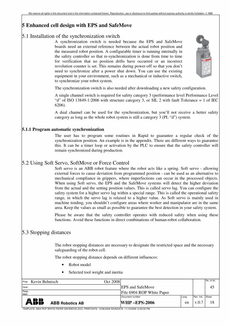
5.1 Installation of the synchronization switch A synchronization switch is needed because the EPS and SafeMove boards need an external reference between the actual robot position and the measured robot position. A configurable timer is running internally in the safety controller so that re-synchronization is done from time to time for verification that no position drifts have occurred or an incorrect revolution counter is set. This remains during power-off so that you don’t need to synchronize after a power shut down. You can use the existing equipment in your environment, such as a mechanical or inductive switch, to synchronize your robot system.
The synchronization switch is also needed after downloading a new safety configuration.
A single channel switch is required for safety category 3 (performance level Performance Level “d” of ISO 13849-1:2006 with structure category 3, or SIL 2 with fault Tolerance = 1 of IEC 6206).
A dual channel can be used for the synchronization, but you’ll not receive a better safety category as long as the whole robot system is still a category 3 (PL “d”) system.
5.1.1 Program automatic synchronization The user has to program some routines in Rapid to guarantee a regular check of the synchronization position. An example is in the appendix. There are different ways to guarantee this. It can be a timer loop or activation by the PLC to ensure that the safety controller will remain synchronized during production.
5.2 Using Soft Servo, SoftMove or Force Control Soft servo is an ABB robot feature where the robot acts like a spring. Soft servo - allowing external forces to cause deviation from programmed position - can be used as an alternative to mechanical compliance in grippers, where imperfections can occur in the processed objects. When using Soft servo, the EPS and the SafeMove systems will detect the higher deviation from the actual and the setting position values. This is called servo lag. You can configure the safety system for a higher servo lag within a special range. This is called the operational safety range, in which the servo lag is relaxed to a higher value. As Soft servo is mainly used in machine tending, you shouldn’t configure areas where worker and manipulator are in the same area. Keep the values as small as possible to guarantee the best detection in your safety system.
Please be aware that the safety controller operates with reduced safety when using these functions. Avoid these functions in direct combinations of human-robot collaboration.
5.3 Stopping distances
The robot stopping distances are necessary to designate the restricted space and the necessary safeguarding of the robot cell.
The robot stopping distance depends on different influences:
• Robot model
• Selected tool weight and inertia
We reserve all rights in this document and in the information contained therein. Reproduction, use or disclosure to third parties without express authority is strictly forbidden. ABB
Document number Lang. Rev. ind. Sheet
ABB Robotics WHP-EPS-SafeMove en v.0.7 19
• Programmed speed
• Used safety equipment
• Brake category.
Total stopping (braking) distance (Tbd)= max. speed robot x (tEPS+text.Equip.)+braking distance robot
Example: Tbd = 200°/s* x (12ms+8ms)+21.8° = 25.8°
For verification of the configuration, you should perform a braking distances test. In this case you should compare the configured axis in EPS with a real stop in an emergency.
You can also use the worst-case stopping distances. This information is available from ABB for every robot type.
5.4 Brake check
The brake check is initiated by the robot controller or an external PLC. The robot moves to a safe position where the brakes are locked with the servos engaged. The motors of the robot are then used to generate a torque. If the robot moves, a category 0 stop occurs and a successful brake check must be performed before the robot can be used again.
With a defined interval (brake cycle time), the robot must move to the safe brake position and activate a switch. If the brake check is not performed within the brake cycle time, the robot is stopped. A warning is shown on the Flexpendant a pre-defined time (pre-warning time) before the brake cycle time has passed. A Cyclic Brake Check can be configured to show a warning but not stop the robot.
5.5 Safety procedures Depending on the solution, special operator training is necessary. A special safety procedure helps protection from additional hazards. So, for cell access for more than one person, an additional enabling switch could be provided or a door lock-out procedure has to be considered.
We reserve all rights in this document and in the information contained therein. Reproduction, use or disclosure to third parties without express authority is strictly forbidden. ABB
Document number Lang. Rev. ind. Sheet
ABB Robotics WHP-EPS-SafeMove en v.0.7 20
5.6 Cell design
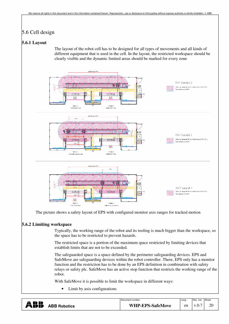
5.6.1 Layout The layout of the robot cell has to be designed for all types of movements and all kinds of different equipment that is used in the cell. In the layout, the restricted workspace should be clearly visible and the dynamic limited areas should be marked for every zone
The picture shows a safety layout of EPS with configured monitor axis ranges for tracked motion
5.6.2 Limiting workspace Typically, the working range of the robot and its tooling is much bigger than the workspace, so the space has to be restricted to prevent hazards.
The restricted space is a portion of the maximum space restricted by limiting devices that establish limits that are not to be exceeded.
The safeguarded space is a space defined by the perimeter safeguarding devices. EPS and SafeMove are safeguarding devices within the robot controller. There, EPS only has a monitor function and the restriction has to be done by an EPS definition in combination with safety relays or safety plc. SafeMove has an active stop function that restricts the working range of the robot.
With SafeMove it is possible to limit the workspace in different ways:
• Limit by axis configurations
We reserve all rights in this document and in the information contained therein. Reproduction, use or disclosure to third parties without express authority is strictly forbidden. ABB
Document number Lang. Rev. ind. Sheet
ABB Robotics WHP-EPS-SafeMove en v.0.7 21
• Cartesian zone definition
• Cartesian zone definition with tool supervision.
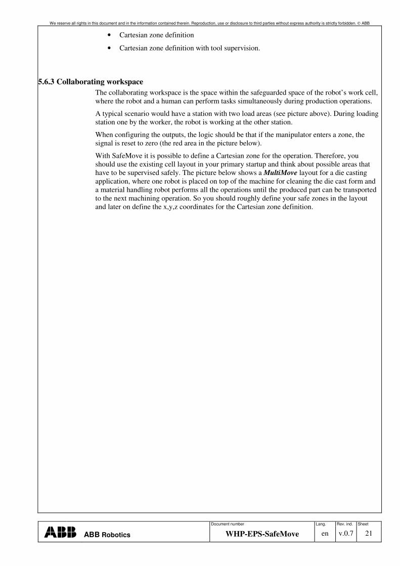
5.6.3 Collaborating workspace The collaborating workspace is the space within the safeguarded space of the robot’s work cell, where the robot and a human can perform tasks simultaneously during production operations.
A typical scenario would have a station with two load areas (see picture above). During loading station one by the worker, the robot is working at the other station.
When configuring the outputs, the logic should be that if the manipulator enters a zone, the signal is reset to zero (the red area in the picture below).
With SafeMove it is possible to define a Cartesian zone for the operation. Therefore, you should use the existing cell layout in your primary startup and think about possible areas that have to be supervised safely. The picture below shows a MultiMove layout for a die casting application, where one robot is placed on top of the machine for cleaning the die cast form and a material handling robot performs all the operations until the produced part can be transported to the next machining operation. So you should roughly define your safe zones in the layout and later on define the x,y,z coordinates for the Cartesian zone definition.
We reserve all rights in this document and in the information contained therein. Reproduction, use or disclosure to third parties without express authority is strictly forbidden. ABB
Document number Lang. Rev. ind. Sheet
ABB Robotics WHP-EPS-SafeMove en v.0.7 22
5.6.4 Collaborating workspace between robots and machinery equipment When using handshakes between the robot and the machine, or between two robots, you should also use the signals from the safety controller to prevent damaging your tool or fixture equipment.
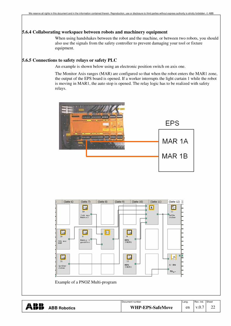
5.6.5 Connections to safety relays or safety PLC An example is shown below using an electronic position switch on axis one.
The Monitor Axis ranges (MAR) are configured so that when the robot enters the MAR1 zone, the output of the EPS board is opened. If a worker interrupts the light curtain 1 while the robot is moving in MAR1, the auto stop is opened. The relay logic has to be realized with safety relays.
Example of a PNOZ Multi-program
We reserve all rights in this document and in the information contained therein. Reproduction, use or disclosure to third parties without express authority is strictly forbidden. ABB
Document number Lang. Rev. ind. Sheet
ABB Robotics WHP-EPS-SafeMove en v.0.7 23
5.7 Cell design with EPS and SafeMove ABB’s new product family SafeMove and EPS are not only intended to replace electric mechanical switches with electronic switches. They also enable new features and functions that could not have been done with robots. In conjunction with the new ISO standard ISO 10218, ABB now offers new possibilities for human-robot interaction and safeguarding
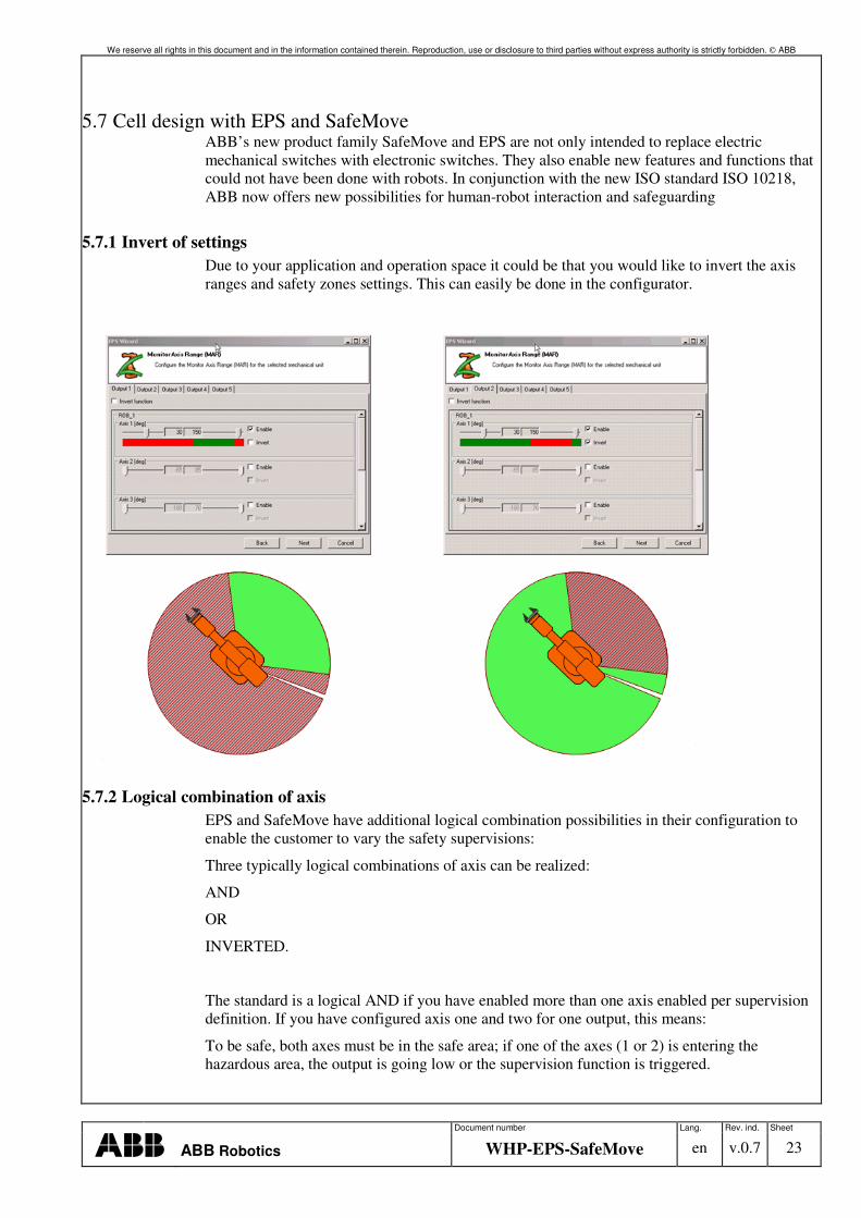
5.7.1 Invert of settings Due to your application and operation space it could be that you would like to invert the axis ranges and safety zones settings. This can easily be done in the configurator.
5.7.2 Logical combination of axis EPS and SafeMove have additional logical combination possibilities in their configuration to enable the customer to vary the safety supervisions:
Three typically logical combinations of axis can be realized:
AND
OR
INVERTED.
The standard is a logical AND if you have enabled more than one axis enabled per supervision definition. If you have configured axis one and two for one output, this means:
To be safe, both axes must be in the safe area; if one of the axes (1 or 2) is entering the hazardous area, the output is going low or the supervision function is triggered.
We reserve all rights in this document and in the information contained therein. Reproduction, use or disclosure to third parties without express authority is strictly forbidden. ABB
Document number Lang. Rev. ind. Sheet
ABB Robotics WHP-EPS-SafeMove en v.0.7 24
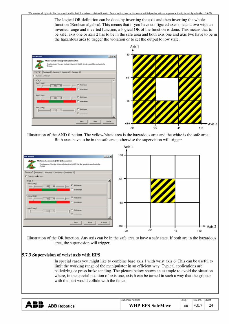
The logical OR definition can be done by inverting the axis and then inverting the whole function (Boolean algebra). This means that if you have configured axes one and two with an inverted range and inverted function, a logical OR of the function is done. This means that to be safe, axis one or axis 2 has to be in the safe area and both axis one and axis two have to be in the hazardous area to trigger the violation or to set the output to low state.
Illustration of the AND function. The yellow/black area is the hazardous area and the white is the safe area.
Both axes have to be in the safe area, otherwise the supervision will trigger.
Illustration of the OR function. Any axis can be in the safe area to have a safe state. If both are in the hazardous
area, the supervision will trigger.
5.7.3 Supervision of wrist axis with EPS In special cases you might like to combine base axis 1 with wrist axis 6. This can be useful to limit the working range of the manipulator in an efficient way. Typical applications are palletizing or press brake tending. The picture below shows an example to avoid the situation where, in the special position of axis one, axis 6 can be turned in such a way that the gripper with the part would collide with the fence.
We reserve all rights in this document and in the information contained therein. Reproduction, use or disclosure to third parties without express authority is strictly forbidden. ABB
Document number Lang. Rev. ind. Sheet
ABB Robotics WHP-EPS-SafeMove en v.0.7 25
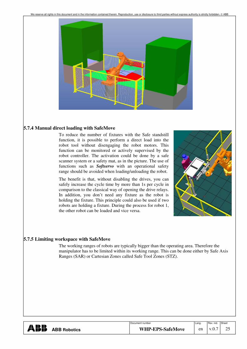
5.7.4 Manual direct loading with SafeMove To reduce the number of fixtures with the Safe standstill function, it is possible to perform a direct load into the robot tool without disengaging the robot motors. This function can be monitored or actively supervised by the robot controller. The activation could be done by a safe scanner system or a safety mat, as in the picture. The use of functions such as Softservo with an operational safety range should be avoided when loading/unloading the robot.
The benefit is that, without disabling the drives, you can safely increase the cycle time by more than 1s per cycle in comparison to the classical way of opening the drive relays. In addition, you don’t need any fixture as the robot is holding the fixture. This principle could also be used if two robots are holding a fixture. During the process for robot 1, the other robot can be loaded and vice versa.
5.7.5 Limiting workspace with SafeMove The working ranges of robots are typically bigger than the operating area. Therefore the manipulator has to be limited within its working range. This can be done either by Safe Axis Ranges (SAR) or Cartesian Zones called Safe Tool Zones (STZ).
We reserve all rights in this document and in the information contained therein. Reproduction, use or disclosure to third parties without express authority is strictly forbidden. ABB
Document number Lang. Rev. ind. Sheet
ABB Robotics WHP-EPS-SafeMove en v.0.7 26
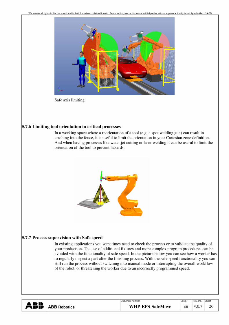
Safe axis limiting
5.7.6 Limiting tool orientation in critical processes In a working space where a reorientation of a tool (e.g. a spot welding gun) can result in crashing into the fence, it is useful to limit the orientation in your Cartesian zone definition. And when having processes like water jet cutting or laser welding it can be useful to limit the orientation of the tool to prevent hazards.
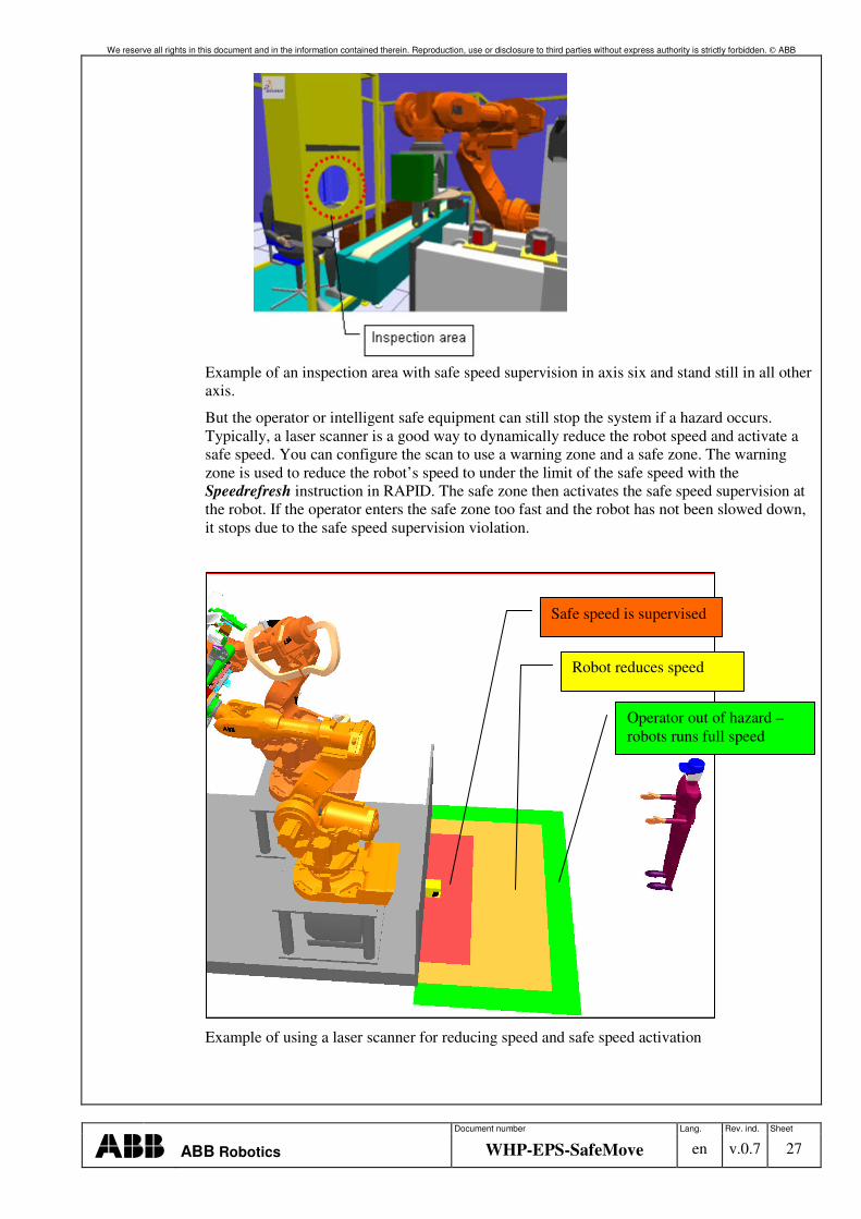
5.7.7 Process supervision with Safe speed In existing applications you sometimes need to check the process or to validate the quality of your production. The use of additional fixtures and more complex program procedures can be avoided with the functionality of safe speed. In the picture below you can see how a worker has to regularly inspect a part after the finishing process. With the safe speed functionality you can still run the process without switching into manual mode or interrupting the overall workflow of the robot, or threatening the worker due to an incorrectly programmed speed.
We reserve all rights in this document and in the information contained therein. Reproduction, use or disclosure to third parties without express authority is strictly forbidden. ABB
Document number Lang. Rev. ind. Sheet
ABB Robotics WHP-EPS-SafeMove en v.0.7 27
Example of an inspection area with safe speed supervision in axis six and stand still in all other axis.
But the operator or intelligent safe equipment can still stop the system if a hazard occurs. Typically, a laser scanner is a good way to dynamically reduce the robot speed and activate a safe speed. You can configure the scan to use a warning zone and a safe zone. The warning zone is used to reduce the robot’s speed to under the limit of the safe speed with the Speedrefresh instruction in RAPID. The safe zone then activates the safe speed supervision at the robot. If the operator enters the safe zone too fast and the robot has not been slowed down, it stops due to the safe speed supervision violation.
Example of using a laser scanner for reducing speed and safe speed activation
Operator out of hazard – robots runs full speed
Safe speed is supervised
Robot reduces speed
We reserve all rights in this document and in the information contained therein. Reproduction, use or disclosure to third parties without express authority is strictly forbidden. ABB
Document number Lang. Rev. ind. Sheet
ABB Robotics WHP-EPS-SafeMove en v.0.7 28
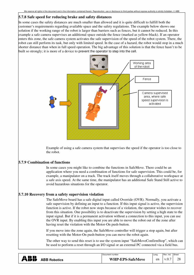
5.7.8 Safe speed for reducing brake and safety distances In some cases the safety distances are much smaller than allowed and it is quite difficult to fulfill both the customer‘s requirements regarding available space and the safety regulations. The example below shows one solution if the working range of the robot is larger than barriers such as fences, but it cannot be reduced. In this example a safe camera supervises an additional space outside the fence (marked as yellow-black). If an operator enters this zone, the safe camera system activates the safe supervision of the speed of the robot system. There, the robot can still perform its task, but only with limited speed. In the case of a hazard, the robot would stop in a much shorter distance than when in full speed operation. The big advantage of this solution is that the fence hasn’t to be built so strongly; it is more of a device to prevent the operator to step into the cell.
Example of using a safe camera system that supervises the speed if the operator is too close to the robot.
5.7.9 Combination of functions In some cases you might like to combine the functions in SafeMove. There could be an application where you need a combination of functions for safe supervision. This could be, for example, a manipulator on a track. The track itself moves through a collaborative workspace at a safe axis speed. At the same time, the manipulator has an additional Safe Stand Still active to avoid hazardous situations for the operator.
5.7.10 Recovery from a safety supervision violation The SafeMove board has a safe digital input called Override (OVR). Normally, you activate a safe supervision by defining an input to a function. If this input signal is active, the supervision function is active. If the robot now stops because of a violation, the operator wishes to recover from this situation. One possibility is to deactivate the supervision by setting a high state to the input signal. But if it is a permanent activation without a connection to this input, you can use the OVR input. By enabling this input you are able to move the robot out of the zone after having reset the violation with the Motor-On push-button.
If you move into the zone again, the SafeMove controller will trigger a stop again, but after resetting with the Motor-On push-button you can move the robot again.
The other way to send this reset is to use the system input “SafeMoveConfirmStop”, which can be used to perform a reset through an I/O signal or an external PC connected via a field bus.
We reserve all rights in this document and in the information contained therein. Reproduction, use or disclosure to third parties without express authority is strictly forbidden. ABB
Document number Lang. Rev. ind. Sheet
ABB Robotics WHP-EPS-SafeMove en v.0.7 29
Another solution for the Override connection is to directly connect the operation mode key selector to the override input of the safety controller board.
5.7.11 Reducing brake distances Reducing the braking distance is always desirable to define shorter layouts and faster worker access to production flow. But, in the main, the definition always has to take care of the maximum speed of the robot. When defining an additional zone with safe speed supervision, the braking distances can be used for this defined safe speed for the risk and distance calculation for the worker access barrier. So the distance can much shorter than in the traditional setup and can save a lot of cycle time.
6 Cost comparison
6.1 EPS savings
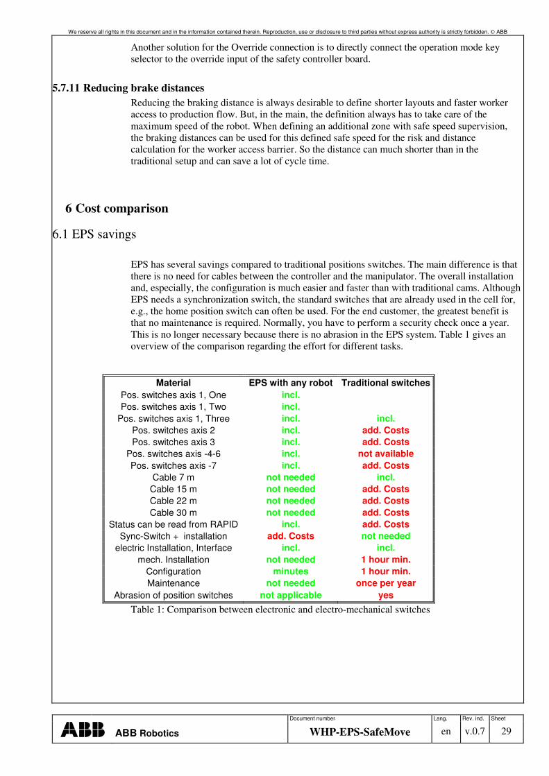
EPS has several savings compared to traditional positions switches. The main difference is that there is no need for cables between the controller and the manipulator. The overall installation and, especially, the configuration is much easier and faster than with traditional cams. Although EPS needs a synchronization switch, the standard switches that are already used in the cell for, e.g., the home position switch can often be used. For the end customer, the greatest benefit is that no maintenance is required. Normally, you have to perform a security check once a year. This is no longer necessary because there is no abrasion in the EPS system. Table 1 gives an overview of the comparison regarding the effort for different tasks.
Material EPS with any robot Traditional switches Pos. switches axis 1, One incl. Pos. switches axis 1, Two incl.
Pos. switches axis 1, Three incl. incl. Pos. switches axis 2 incl. add. Costs Pos. switches axis 3 incl. add. Costs
Pos. switches axis -4-6 incl. not available Pos. switches axis -7 incl. add. Costs
Cable 7 m not needed incl. Cable 15 m not needed add. Costs Cable 22 m not needed add. Costs Cable 30 m not needed add. Costs
Status can be read from RAPID incl. add. Costs Sync-Switch + installation add. Costs not needed
electric Installation, Interface incl. incl. mech. Installation not needed 1 hour min.
Configuration minutes 1 hour min. Maintenance not needed once per year
Abrasion of position switches not applicable yes
Table 1: Comparison between electronic and electro-mechanical switches
We reserve all rights in this document and in the information contained therein. Reproduction, use or disclosure to third parties without express authority is strictly forbidden. ABB
Document number Lang. Rev. ind. Sheet
ABB Robotics WHP-EPS-SafeMove en v.0.7 30
6.2 SafeMove savings
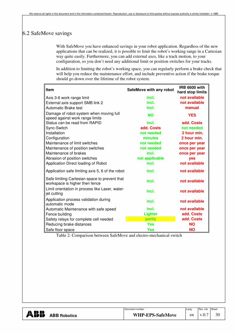
With SafeMove you have enhanced savings in your robot application. Regardless of the new applications that can be realized, it is possible to limit the robot’s working range in a Cartesian way quite easily. Furthermore, you can add external axes, like a track motion, to your configuration, so you don’t need any additional limit or position switches for your tracks.
In addition to limiting the robot’s working space, you can regularly perform a brake check that will help you reduce the maintenance effort, and include preventive action if the brake torque should go down over the lifetime of the robot system.
Item SafeMove with any robot IRB 6600 with hard stop limits
Axis 3-6 work range limit incl. not available External axis support SMB link 2 incl. not available Automatic Brake test incl. manual Damage of robot system when moving full speed against work range limits
NO YES
Status can be read from RAPID incl. add. Costs Sync-Switch add. Costs not needed Installation not needed 2 hour min. Configuration minutes 2 hour min. Maintenance of limit switches not needed once per year Maintenance of position switches not needed once per year Maintenance of brakes incl. once per year Abrasion of position switches not applicable yes Application Direct loading of Robot incl. not available
Application safe limiting axis 5, 6 of the robot incl. not available
Safe limiting Cartesian space to prevent that workspace is higher then fence incl. not available
Limit orientation in process like Laser, water-jet cutting incl. not available
Application process validation during automatic mode
incl. not available
Automatic Maintenance with safe speed incl. not available Fence building Lighter add. Costs Safety relays for complete cell needed partly add. Costs Reducing brake distances Yes NO Safe floor space Yes NO
Table 2: Comparison between SafeMove and electro-mechanical switch
We reserve all rights in this document and in the information contained therein. Reproduction, use or disclosure to third parties without express authority is strictly forbidden. ABB
Document number Lang. Rev. ind. Sheet
ABB Robotics WHP-EPS-SafeMove en v.0.7 31
7 Conclusions
With the new EPS and SafeMove functions, ABB offers new possibilities to enhance safety in the cell. With SafeMove in particular, you have a great new function to limit the work space and realize new applications in robot automation.
Overall, there some rules for success in the use of the ABB safety system:
• Read the documentation on the robot system
• Before using safety equipment or connecting external equipment to the robot’s safety interface, be familiar with the necessary documents (user manuals, safety circuit diagram)
• Don’t use non-safe software features for safety purposes (Rapid World zones)
• Be aware of the braking distances
• Check the braking distances in your application
• Always use 0V as a safe state – Wire braking technology
• Always check your safety configurations
• Identify and report risks
• Have a different person check your configuration
We reserve all rights in this document and in the information contained therein. Reproduction, use or disclosure to third parties without express authority is strictly forbidden. ABB
Document number Lang. Rev. ind. Sheet
ABB Robotics WHP-EPS-SafeMove en v.0.7 32
8 Appendix A: EPS Examples
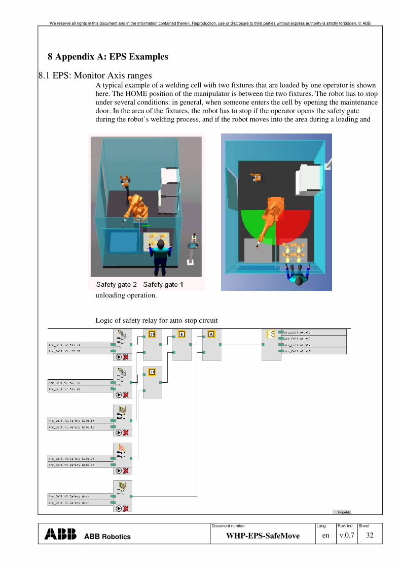
8.1 EPS: Monitor Axis ranges A typical example of a welding cell with two fixtures that are loaded by one operator is shown here. The HOME position of the manipulator is between the two fixtures. The robot has to stop under several conditions: in general, when someone enters the cell by opening the maintenance door. In the area of the fixtures, the robot has to stop if the operator opens the safety gate during the robot’s welding process, and if the robot moves into the area during a loading and
unloading operation.
Logic of safety relay for auto-stop circuit
We reserve all rights in this document and in the information contained therein. Reproduction, use or disclosure to third parties without express authority is strictly forbidden. ABB
Document number Lang. Rev. ind. Sheet
ABB Robotics WHP-EPS-SafeMove en v.0.7 33
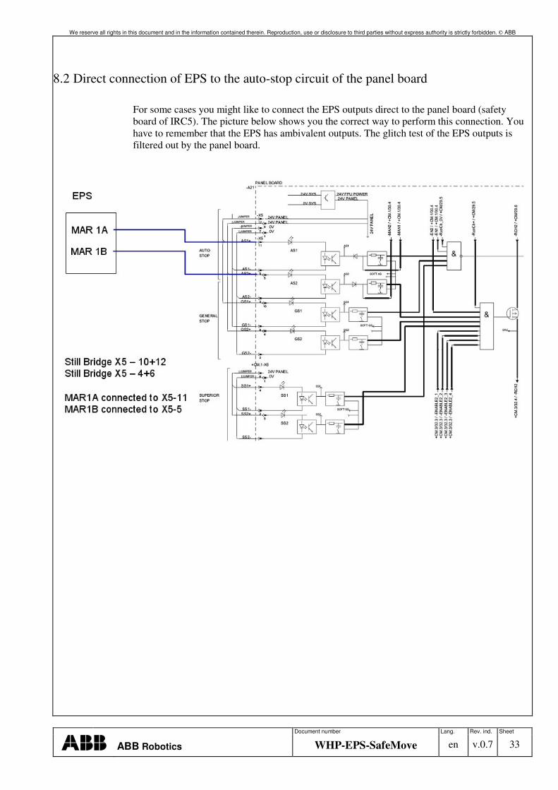
8.2 Direct connection of EPS to the auto-stop circuit of the panel board
For some cases you might like to connect the EPS outputs direct to the panel board (safety board of IRC5). The picture below shows you the correct way to perform this connection. You have to remember that the EPS has ambivalent outputs. The glitch test of the EPS outputs is filtered out by the panel board.
We reserve all rights in this document and in the information contained therein. Reproduction, use or disclosure to third parties without express authority is strictly forbidden. ABB
Document number Lang. Rev. ind. Sheet
ABB Robotics WHP-EPS-SafeMove en v.0.7 34
9 Appendix B: SafeMove Examples
9.1 Monitor ToolZones and SafeToolZones
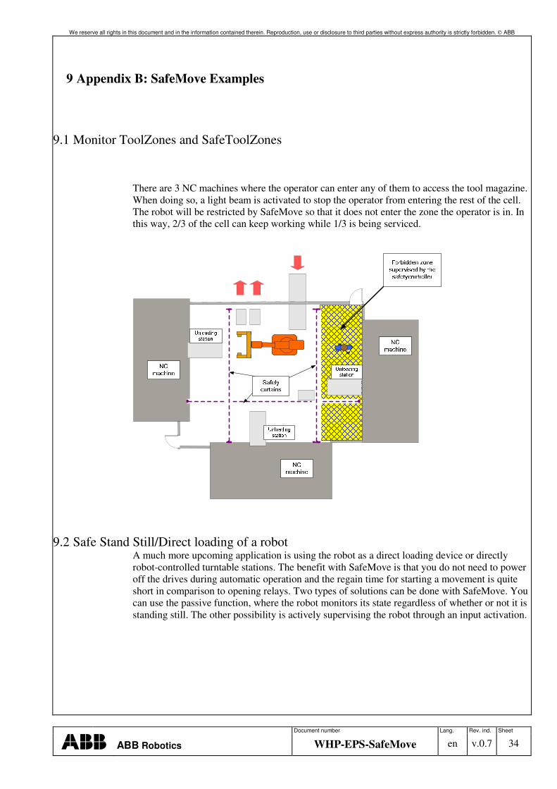
There are 3 NC machines where the operator can enter any of them to access the tool magazine. When doing so, a light beam is activated to stop the operator from entering the rest of the cell. The robot will be restricted by SafeMove so that it does not enter the zone the operator is in. In this way, 2/3 of the cell can keep working while 1/3 is being serviced.
9.2 Safe Stand Still/Direct loading of a robot A much more upcoming application is using the robot as a direct loading device or directly robot-controlled turntable stations. The benefit with SafeMove is that you do not need to power off the drives during automatic operation and the regain time for starting a movement is quite short in comparison to opening relays. Two types of solutions can be done with SafeMove. You can use the passive function, where the robot monitors its state regardless of whether or not it is standing still. The other possibility is actively supervising the robot through an input activation.
We reserve all rights in this document and in the information contained therein. Reproduction, use or disclosure to third parties without express authority is strictly forbidden. ABB
Document number Lang. Rev. ind. Sheet
ABB Robotics WHP-EPS-SafeMove en v.0.7 35
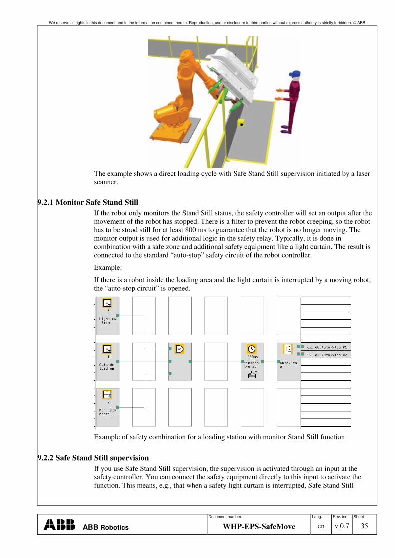
The example shows a direct loading cycle with Safe Stand Still supervision initiated by a laser scanner.
9.2.1 Monitor Safe Stand Still If the robot only monitors the Stand Still status, the safety controller will set an output after the movement of the robot has stopped. There is a filter to prevent the robot creeping, so the robot has to be stood still for at least 800 ms to guarantee that the robot is no longer moving. The monitor output is used for additional logic in the safety relay. Typically, it is done in combination with a safe zone and additional safety equipment like a light curtain. The result is connected to the standard “auto-stop” safety circuit of the robot controller.
Example:
If there is a robot inside the loading area and the light curtain is interrupted by a moving robot, the “auto-stop circuit” is opened.
Example of safety combination for a loading station with monitor Stand Still function
9.2.2 Safe Stand Still supervision If you use Safe Stand Still supervision, the supervision is activated through an input at the safety controller. You can connect the safety equipment directly to this input to activate the function. This means, e.g., that when a safety light curtain is interrupted, Safe Stand Still
We reserve all rights in this document and in the information contained therein. Reproduction, use or disclosure to third parties without express authority is strictly forbidden. ABB
Document number Lang. Rev. ind. Sheet
ABB Robotics WHP-EPS-SafeMove en v.0.7 36
Granted orientation
supervision is active. If the robot should move at this moment, the safety controller detects this and stops the manipulator by opening the internal limit switch.
9.3 Safe Axis ranges with track Motions Track motions are often associated with the need for safe zones, due to the physical extension of a track and/or the use of multiple work/loading/unloading stations. In principle, tracks can also be dealt with by EPS, but SafeMove brings the benefit of connecting to the serial measurement board 2 (to which most tracks are connected), an increased number of zones and, of course, all the SafeMove features in general.
In the example in the picture, zones are constructed out of a combination of axes 1 and 7. When a truck is loading/unloading a specific station, axis 1 is prevented from going to the loading side if axis 7 is within the loading zone reserved by the truck.
Example: Palletizing station with robot on a track motion
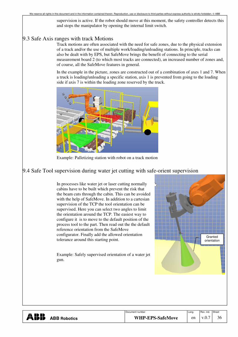
9.4 Safe Tool supervision during water jet cutting with safe-orient supervision
In processes like water jet or laser cutting normally cabins have to be built which prevent the risk that the beam cuts through the cabin. This can be avoided with the help of SafeMove. In addition to a cartesian supervision of the TCP the tool orientation can be supervised. Here you can select two angles to limit the orientation around the TCP. The easiest way to configure it is to move to the default position of the process tool to the part. Then read out the the default reference orientation from the SafeMove configurator. Finally add the allowed orientation tolerance around this starting point.
Example: Safely supervised orientation of a water jet gun.

We reserve all rights in this document and in the information contained therein. Reproduction, use or disclosure to third parties without express authority is strictly forbidden. ABB
Document number Lang. Rev. ind. Sheet
ABB Robotics WHP-EPS-SafeMove en v.0.7 37
10 Appendix C: EIO Definition for EPS
There should be cross-connection created in the I/O-configuration EIO.cfg using signals in the Rapid program flow.
Name of internal signal
Meaning Name in Virtual I/O Unit
PSC1CSC Cyclic sync check, Active on closing edge of the sync switch
diEPS_SyncSwitch
PSC1CSPREWARN Pre-warning signal for the synchronization. This signal is set when the pre-warning message is sent by the safety controller: This signal is available from RW 5.10.2
doPSC1CSPreWarn
PSC1CSS Cyclic sync status, 0 = Not synchronized diEPS_Sync
PSC1MAR1 Monitor axis range 1, 0 = Axis out of range doPSC1MAR1
The internal signals are updated at a rate of 500 ms; the real physical signals are updated within 4 ms in relation to the ordered axis value.
EIO:CFG_1.0:5:0:: # EIO_UNIT: -Name "MyVirtualEPS" -UnitType "Virtual" -Bus "Virtual1" # EIO_SIGNAL: -Name "diEPS_SyncSwitch" -SignalType "DI" -Unit "MyVirtualEPS" -UnitMap "0"\ -Access "ALL" -Name "diEPS_Sync" -SignalType "DI" -Unit "MyVirtualEPS" -UnitMap "1"\ -Access "ALL" -Name "doPSC1CALIBRATED" -SignalType "DO" -Unit "MyVirtualEPS"\ -UnitMap "0" -Access "ALL" -Name "doPSC1MAR1" -SignalType "DO" -Unit "MyVirtualEPS" -UnitMap "1"\ -Access "ALL" -Name "doPSC1MAR2" -SignalType "DO" -Unit "MyVirtualEPS" -UnitMap "2"\ -Access "ALL" -Name "doPSC1MAR3" -SignalType "DO" -Unit "MyVirtualEPS" -UnitMap "3"\ -Access "ALL" -Name "doPSC1MAR4" -SignalType "DO" -Unit "MyVirtualEPS" -UnitMap "4"\ -Access "ALL"
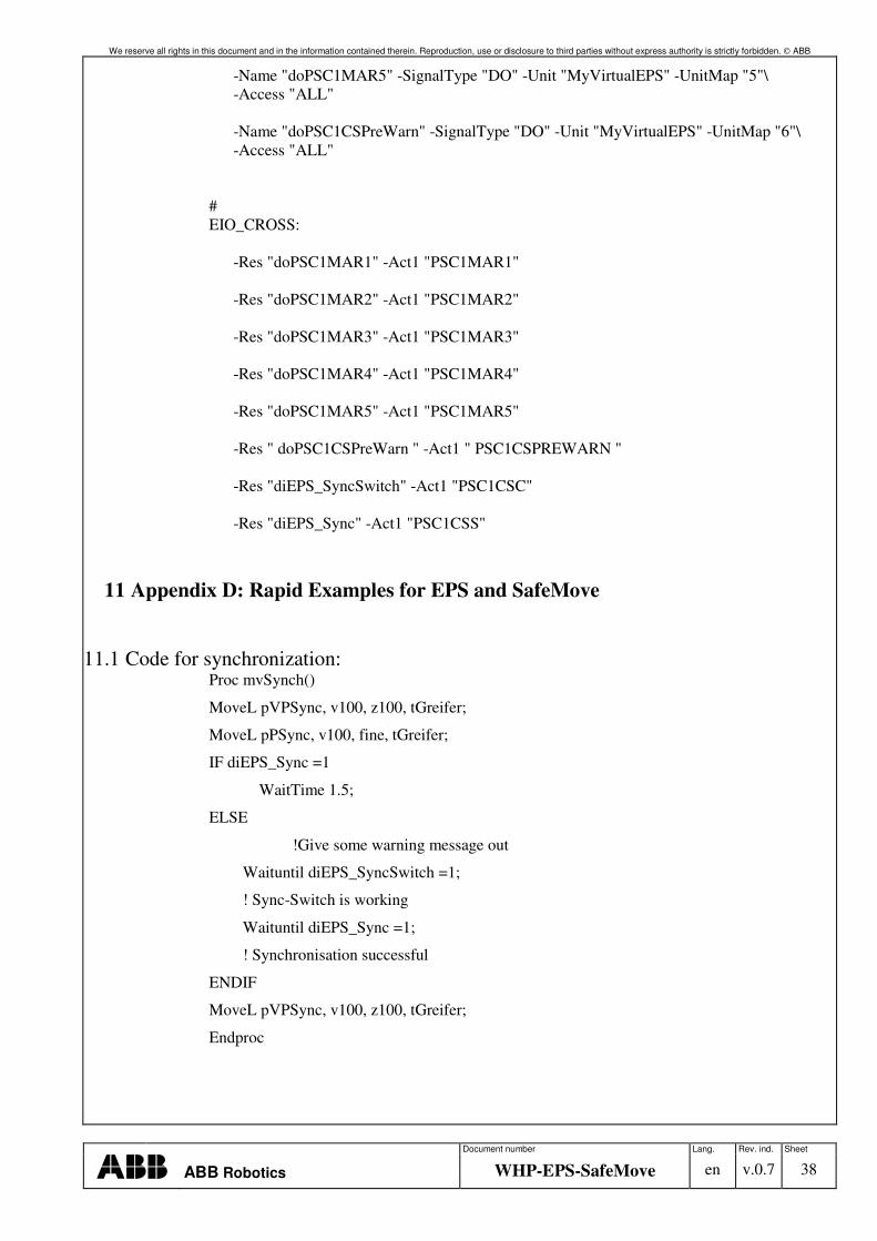
We reserve all rights in this document and in the information contained therein. Reproduction, use or disclosure to third parties without express authority is strictly forbidden. ABB
Document number Lang. Rev. ind. Sheet
ABB Robotics WHP-EPS-SafeMove en v.0.7 38
-Name "doPSC1MAR5" -SignalType "DO" -Unit "MyVirtualEPS" -UnitMap "5"\ -Access "ALL" -Name "doPSC1CSPreWarn" -SignalType "DO" -Unit "MyVirtualEPS" -UnitMap "6"\ -Access "ALL" # EIO_CROSS: -Res "doPSC1MAR1" -Act1 "PSC1MAR1" -Res "doPSC1MAR2" -Act1 "PSC1MAR2" -Res "doPSC1MAR3" -Act1 "PSC1MAR3" -Res "doPSC1MAR4" -Act1 "PSC1MAR4" -Res "doPSC1MAR5" -Act1 "PSC1MAR5" -Res " doPSC1CSPreWarn " -Act1 " PSC1CSPREWARN " -Res "diEPS_SyncSwitch" -Act1 "PSC1CSC" -Res "diEPS_Sync" -Act1 "PSC1CSS"
11 Appendix D: Rapid Examples for EPS and SafeMove
11.1 Code for synchronization: Proc mvSynch()
MoveL pVPSync, v100, z100, tGreifer;
MoveL pPSync, v100, fine, tGreifer;
IF diEPS_Sync =1
WaitTime 1.5;
ELSE
!Give some warning message out
Waituntil diEPS_SyncSwitch =1;
! Sync-Switch is working
Waituntil diEPS_Sync =1;
! Synchronisation successful
ENDIF
MoveL pVPSync, v100, z100, tGreifer;
Endproc
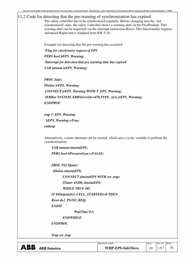
We reserve all rights in this document and in the information contained therein. Reproduction, use or disclosure to third parties without express authority is strictly forbidden. ABB
Document number Lang. Rev. ind. Sheet
ABB Robotics WHP-EPS-SafeMove en v.0.7 39
11.2 Code for detecting that the pre-warning of synchronization has expired The safety controller has to be synchronized regularly. Before changing into the ”not synchronized“ state, the safety controller shows a warning alert on the FlexPendant. This warning alert can be requested via the interrupt instruction IError. This functionality requires Advanced Rapid and is standard from RW 5.10.
Example for detecting that the pre-warning has occurred:
!Flag for synchronize request of EPS
PERS bool bEPS_Warning;
!Interrupt for detection that pre warning time has expired
VAR intnum irEPS_Warning;
PROC Init()
IDelete irEPS_Warning;
CONNECT irEPS_Warning WITH T_EPS_Warning;
IERRor SYSTEM_ERR\ErrorId:=470,TYPE_ALL,irEPS_Warning;
ENDPROC
trap T_EPS_Warning
bEPS_Warning:=True;
endtrap
Alternatively, a timer interrupt can be created, which sets a cyclic variable to perform the synchronization:
VAR intnum timeintEPS;
PERS bool bPrewarnSync:=FALSE;
PROC PLCMain()
IDelete timeintEPS;
CONNECT timeintEPS WITH err_trap;
ITimer 43200, timeintEPS;
WHILE TRUE DO
IF DOutput(do5_CELL_STARTED)=0 THEN
Reset do1_PGNO_REQ;
ENDIF
WaitTime 0.5;
ENDWHILE
ENDPROC
Trap err_trap
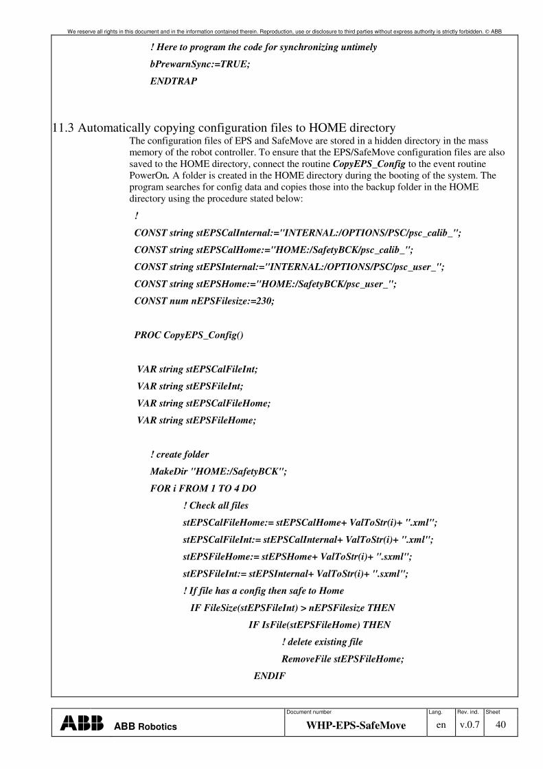
We reserve all rights in this document and in the information contained therein. Reproduction, use or disclosure to third parties without express authority is strictly forbidden. ABB
Document number Lang. Rev. ind. Sheet
ABB Robotics WHP-EPS-SafeMove en v.0.7 40
! Here to program the code for synchronizing untimely
bPrewarnSync:=TRUE;
ENDTRAP
11.3 Automatically copying configuration files to HOME directory The configuration files of EPS and SafeMove are stored in a hidden directory in the mass memory of the robot controller. To ensure that the EPS/SafeMove configuration files are also saved to the HOME directory, connect the routine CopyEPS_Config to the event routine PowerOn. A folder is created in the HOME directory during the booting of the system. The program searches for config data and copies those into the backup folder in the HOME directory using the procedure stated below:
!
CONST string stEPSCalInternal:="INTERNAL:/OPTIONS/PSC/psc_calib_";
CONST string stEPSCalHome:="HOME:/SafetyBCK/psc_calib_";
CONST string stEPSInternal:="INTERNAL:/OPTIONS/PSC/psc_user_";
CONST string stEPSHome:="HOME:/SafetyBCK/psc_user_";
CONST num nEPSFilesize:=230;
PROC CopyEPS_Config()
VAR string stEPSCalFileInt;
VAR string stEPSFileInt;
VAR string stEPSCalFileHome;
VAR string stEPSFileHome;
! create folder
MakeDir "HOME:/SafetyBCK";
FOR i FROM 1 TO 4 DO
! Check all files
stEPSCalFileHome:= stEPSCalHome+ ValToStr(i)+ ".xml";
stEPSCalFileInt:= stEPSCalInternal+ ValToStr(i)+ ".xml";
stEPSFileHome:= stEPSHome+ ValToStr(i)+ ".sxml";
stEPSFileInt:= stEPSInternal+ ValToStr(i)+ ".sxml";
! If file has a config then safe to Home
IF FileSize(stEPSFileInt) > nEPSFilesize THEN
IF IsFile(stEPSFileHome) THEN
! delete existing file
RemoveFile stEPSFileHome;
ENDIF
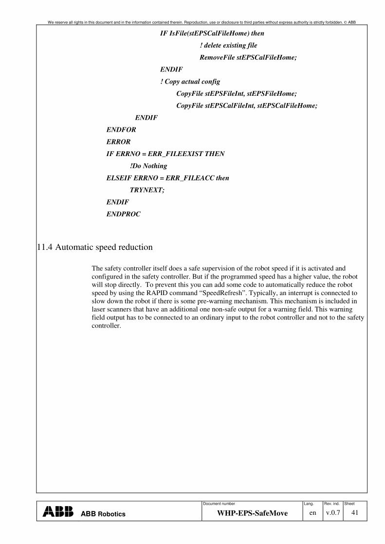
We reserve all rights in this document and in the information contained therein. Reproduction, use or disclosure to third parties without express authority is strictly forbidden. ABB
Document number Lang. Rev. ind. Sheet
ABB Robotics WHP-EPS-SafeMove en v.0.7 41
IF IsFile(stEPSCalFileHome) then
! delete existing file
RemoveFile stEPSCalFileHome;
ENDIF
! Copy actual config
CopyFile stEPSFileInt, stEPSFileHome;
CopyFile stEPSCalFileInt, stEPSCalFileHome;
ENDIF
ENDFOR
ERROR
IF ERRNO = ERR_FILEEXIST THEN
!Do Nothing
ELSEIF ERRNO = ERR_FILEACC then
TRYNEXT;
ENDIF
ENDPROC
11.4 Automatic speed reduction
The safety controller itself does a safe supervision of the robot speed if it is activated and configured in the safety controller. But if the programmed speed has a higher value, the robot will stop directly. To prevent this you can add some code to automatically reduce the robot speed by using the RAPID command “SpeedRefresh”. Typically, an interrupt is connected to slow down the robot if there is some pre-warning mechanism. This mechanism is included in laser scanners that have an additional one non-safe output for a warning field. This warning field output has to be connected to an ordinary input to the robot controller and not to the safety controller.
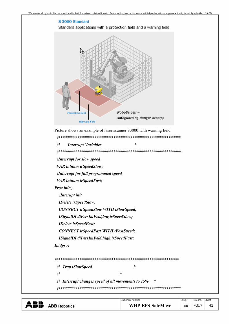
We reserve all rights in this document and in the information contained therein. Reproduction, use or disclosure to third parties without express authority is strictly forbidden. ABB
Document number Lang. Rev. ind. Sheet
ABB Robotics WHP-EPS-SafeMove en v.0.7 42
Picture shows an example of laser scanner S3000 with warning field
!**********************************************************
!* Interrupt Variables *
!**********************************************************
!Interrupt for slow speed
VAR intnum irSpeedSlow;
!Interrupt for full programmed speed
VAR intnum irSpeedFast;
Proc init()
!Interupt init
IDelete irSpeedSlow;
CONNECT irSpeedSlow WITH tSlowSpeed;
ISignalDI diPersImFeld,low,irSpeedSlow;
IDelete irSpeedFast;
CONNECT irSpeedFast WITH tFastSpeed;
ISignalDI diPersImFeld,high,irSpeedFast;
Endproc
!**********************************************************
!* Trap tSlowSpeed *
!* *
!* Interrupt changes speed of all movements to 15% *
!**********************************************************
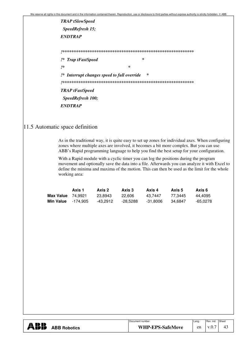
We reserve all rights in this document and in the information contained therein. Reproduction, use or disclosure to third parties without express authority is strictly forbidden. ABB
Document number Lang. Rev. ind. Sheet
ABB Robotics WHP-EPS-SafeMove en v.0.7 43
TRAP tSlowSpeed
SpeedRefresh 15;
ENDTRAP
!**********************************************************
!* Trap tFastSpeed *
!* *
!* Interrupt changes speed to full override *
!**********************************************************
TRAP tFastSpeed
SpeedRefresh 100;
ENDTRAP
11.5 Automatic space definition
As in the traditional way, it is quite easy to set up zones for individual axes. When configuring zones where multiple axes are involved, it becomes a bit more complex. But you can use ABB’s Rapid programming language to help you find the best setup for your configuration.
With a Rapid module with a cyclic timer you can log the positions during the program movement and optionally save the data into a file. Afterwards you can analyze it with Excel to define the minima and maxima of the motion. This can then be used as the limit for the whole working area:
Axis 1 Axis 2 Axis 3 Axis 4 Axis 5 Axis 6 Max Value 74,9921 23,8943 22,606 43,7447 77,3445 44,4095 Min Value -174,905 -43,2912 -28,5288 -31,8006 34,6847 -65,0278
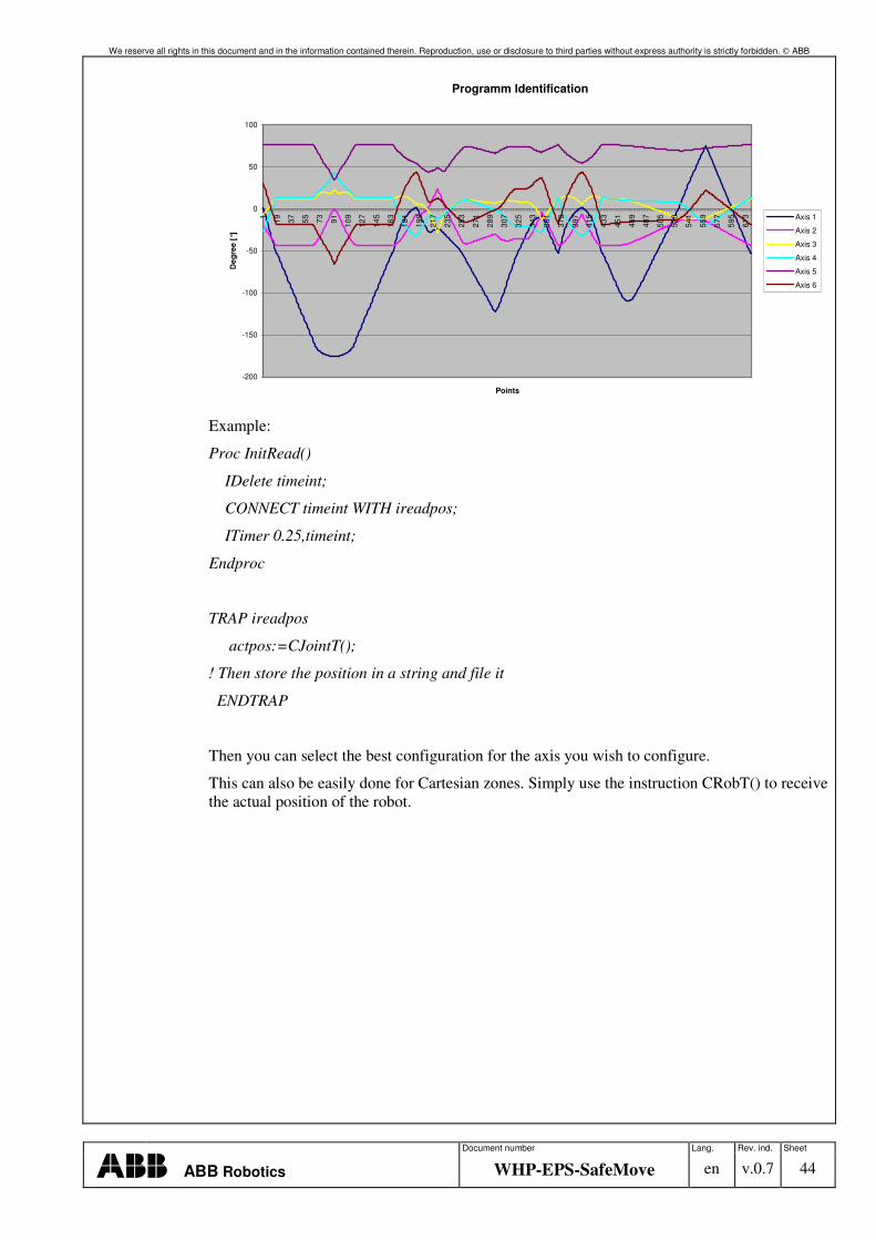
We reserve all rights in this document and in the information contained therein. Reproduction, use or disclosure to third parties without express authority is strictly forbidden. ABB
Document number Lang. Rev. ind. Sheet
ABB Robotics WHP-EPS-SafeMove en v.0.7 44
Programm Identification
-200
-150
-100
-50
0
50
100
1 19 37 55 73 91 109
127
145
163
181
199
217
235
253
271
289
307
325
343
361
379
397
415
433
451
469
487
505
523
541
559
577
595
613
Points
Deg
ree
[°]
Axis 1
Axis 2
Axis 3
Axis 4
Axis 5
Axis 6
Example:
Proc InitRead()
IDelete timeint;
CONNECT timeint WITH ireadpos;
ITimer 0.25,timeint;
Endproc
TRAP ireadpos
actpos:=CJointT();
! Then store the position in a string and file it
ENDTRAP
Then you can select the best configuration for the axis you wish to configure.
This can also be easily done for Cartesian zones. Simply use the instruction CRobT() to receive the actual position of the robot.
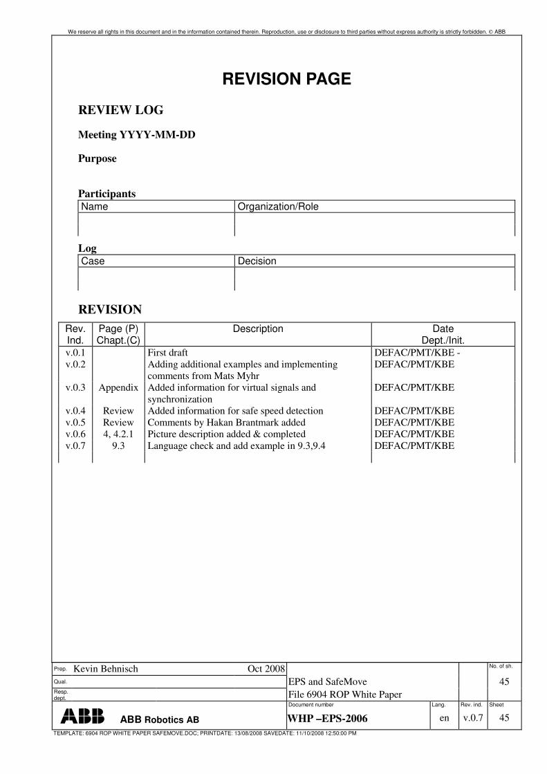
We reserve all rights in this document and in the information contained therein. Reproduction, use or disclosure to third parties without express authority is strictly forbidden. ABB
Prep. Kevin Behnisch Oct 2008 No. of sh.
Qual. EPS and SafeMove
45 Resp. dept. File 6904 ROP White Paper
SafeMove.doc
Document number Lang. Rev. ind. Sheet
ABB Robotics AB WHP –EPS-2006 en v.0.7 45 TEMPLATE: 6904 ROP WHITE PAPER SAFEMOVE.DOC; PRINTDATE: 13/08/2008 SAVEDATE: 11/10/2008 12:50:00 PM
REVISION PAGE
REVIEW LOG
Meeting YYYY-MM-DD
Purpose
Participants Name Organization/Role
Log Case Decision
REVISION Rev. Ind.
Page (P) Chapt.(C)
Description Date Dept./Init.
v.0.1 First draft DEFAC/PMT/KBE - v.0.2 Adding additional examples and implementing
comments from Mats Myhr DEFAC/PMT/KBE
v.0.3 Appendix Added information for virtual signals and synchronization
DEFAC/PMT/KBE
v.0.4 Review Added information for safe speed detection DEFAC/PMT/KBE v.0.5 Review Comments by Hakan Brantmark added DEFAC/PMT/KBE v.0.6 4, 4.2.1 Picture description added & completed DEFAC/PMT/KBE v.0.7 9.3 Language check and add example in 9.3,9.4 DEFAC/PMT/KBE