Embed Size (px)
Citation preview
2012-12-03
1
3DS
.CO
M/S
IMU
LIA
© D
assa
ult S
ystè
mes
| C
onfid
entia
l Inf
orm
atio
n | 1
2/3/
2012
| re
f.: 3
DS
_Doc
umen
t_20
12
1
3DS
.CO
M ©
Das
saul
t Sys
tèm
es |
Con
fiden
tial I
nfor
mat
ion
| 12/
3/20
12 |
ref.
: 3D
S_D
ocum
ent_
2012
Failure Prediction
without Prescribing Crack Paths
by using XFEM in Abaqus
Jun Park, Ph. D.
Nov. 23rd, 2012
3DS
.CO
M/S
IMU
LIA
© D
assa
ult S
ystè
mes
| C
onfid
entia
l Inf
orm
atio
n | 1
2/3/
2012
| re
f.: 3
DS
_Doc
umen
t_20
12
2
Where do cracks initiate?
What is the direction of propagation?

2012-12-03
2
3DS
.CO
M/S
IMU
LIA
© D
assa
ult S
ystè
mes
| C
onfid
entia
l Inf
orm
atio
n | 1
2/3/
2012
| re
f.: 3
DS
_Doc
umen
t_20
12
3
Test
Simulation
3DS
.CO
M/S
IMU
LIA
© D
assa
ult S
ystè
mes
| C
onfid
entia
l Inf
orm
atio
n | 1
2/3/
2012
| re
f.: 3
DS
_Doc
umen
t_20
12
4
Outline of the Presentation
Motivations for using XFEM
Introduction to XFEM
Multi-year developments
Examples of applying XFEM
Summary

2012-12-03
3
3DS
.CO
M/S
IMU
LIA
© D
assa
ult S
ystè
mes
| C
onfid
entia
l Inf
orm
atio
n | 1
2/3/
2012
| re
f.: 3
DS
_Doc
umen
t_20
12
5
Motivations for Using XFEM Strong technology exists in Abaqus:
Interfacial cracks with VCCT and cohesive element techniques
Smeared crack approach to continuum damage initiation and evolution in the bulk materials
Main challenges of the existing technology:
Modeling and analysis of stationary 3-D curved surface cracks
Progressive crack growth simulations for arbitrary 3-D cracks
eXtended Finite Element Method (XFEM) has become relatively mature to be commercialized since it was first introduced by Belyschko and Black in 1999.
3DS
.CO
M/S
IMU
LIA
© D
assa
ult S
ystè
mes
| C
onfid
entia
l Inf
orm
atio
n | 1
2/3/
2012
| re
f.: 3
DS
_Doc
umen
t_20
12
6
Motivation for Using XFEM
Makes modeling of cracks easier and more accurate:
Exhibits almost no mesh dependence if the mesh is sufficiently refined
Allows the simulation of initiation and propagation of a discrete crack along an
arbitrary, solution-dependent path without the requirement of remeshing
Supports contour integral evaluation for a stationary crack

2012-12-03
4
3DS
.CO
M/S
IMU
LIA
© D
assa
ult S
ystè
mes
| C
onfid
entia
l Inf
orm
atio
n | 1
2/3/
2012
| re
f.: 3
DS
_Doc
umen
t_20
12
7
Introduction to XFEM
XFEM is an extension of the conventional finite element method based on the
concept of partition of unity.
It allows the presence of discontinuities in an element by enriching degrees of
freedom with special displacement functions.
4
1 1
( ) ( ) ( )N
I I I I
I
N H F
u x u x a x b
To capture the displacement jump
across the crack faces To capture the crack-tip
behavior
*1 0,( )
1
ifH
otherwise
x x nx
3DS
.CO
M/S
IMU
LIA
© D
assa
ult S
ystè
mes
| C
onfid
entia
l Inf
orm
atio
n | 1
2/3/
2012
| re
f.: 3
DS
_Doc
umen
t_20
12
8
Introduction to XFEM
Applies to nodes whose
shape function support is
cut by the crack interior
Applies to nodes whose
shape function support is
cut by the crack tip
Applies to all nodes in
the model
4
1 1
( ) ( ) ( )N
I I I I
I
N H F
u x u x a x b
Depend on:
•The crack location
•The material

2012-12-03
5
3DS
.CO
M/S
IMU
LIA
© D
assa
ult S
ystè
mes
| C
onfid
entia
l Inf
orm
atio
n | 1
2/3/
2012
| re
f.: 3
DS
_Doc
umen
t_20
12
9
Introduction to XFEM
Level set method
Is a numerical technique for describing a crack and tracking the motion of the crack
Couples naturally with XFEM and makes possible the modeling of 3D arbitrary crack growth without remeshing
Requires two level sets for a crack:
The first describes the crack surface
The second is constructed so that its intersection with the first gives the crack front
Uses signed distance functions to describe the crack geometry
Does not require explicit representation of the crack: the crack is entirely described by nodal data
3DS
.CO
M/S
IMU
LIA
© D
assa
ult S
ystè
mes
| C
onfid
entia
l Inf
orm
atio
n | 1
2/3/
2012
| re
f.: 3
DS
_Doc
umen
t_20
12
10
XFEM Features Introduced in 6.9 (XFEM I)
XFEM was first introduced for
The static procedure
First-order solid continuum stress/displacement elements:
Stationary cracks without support for the contour integral output
Propagating cracks with cohesive segments
2012-12-03
6
3DS
.CO
M/S
IMU
LIA
© D
assa
ult S
ystè
mes
| C
onfid
entia
l Inf
orm
atio
n | 1
2/3/
2012
| re
f.: 3
DS
_Doc
umen
t_20
12
11
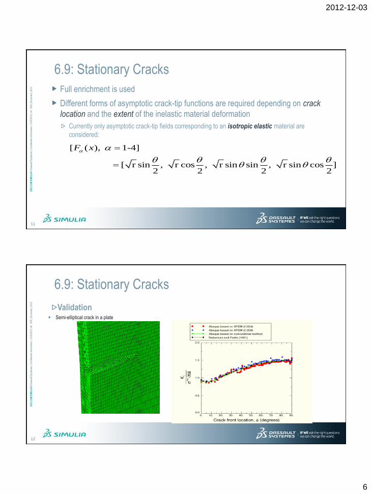
6.9: Stationary Cracks
Full enrichment is used
Different forms of asymptotic crack-tip functions are required depending on crack
location and the extent of the inelastic material deformation
Currently only asymptotic crack-tip fields corresponding to an isotropic elastic material are
considered:
[ ( ), 1-4]
[ r sin , r cos , r sin sin , r sin cos ]2 2 2 2
F x
3DS
.CO
M/S
IMU
LIA
© D
assa
ult S
ystè
mes
| C
onfid
entia
l Inf
orm
atio
n | 1
2/3/
2012
| re
f.: 3
DS
_Doc
umen
t_20
12
12
6.9: Stationary Cracks
Validation Semi-elliptical crack in a plate

2012-12-03
7
3DS
.CO
M/S
IMU
LIA
© D
assa
ult S
ystè
mes
| C
onfid
entia
l Inf
orm
atio
n | 1
2/3/
2012
| re
f.: 3
DS
_Doc
umen
t_20
12
13
6.9: Propagating Cracks
“Phantom nodes” and cohesive segments
Can be used for brittle or ductile fracture
Pressure-overclosure relationship governs the behavior when the crack
is “closed”
Cohesive behavior contributes to the contact normal stress when the crack is “open”
3DS
.CO
M/S
IMU
LIA
© D
assa
ult S
ystè
mes
| C
onfid
entia
l Inf
orm
atio
n | 1
2/3/
2012
| re
f.: 3
DS
_Doc
umen
t_20
12
14
XFEM Features Introduced in 6.9-EF (XFEM II)
Support for:
Contour integral evaluation in a fracture analysis that uses XFEM
(*CONTOUR INTEGRAL, XFEM)
User-specified value of the enrichment radius for stationary crack singularity calculations
(*ENRICHMENT, ENRICHMENT RADIUS)
Better convergence due to the introduction of the viscous regularization
of the constitutive equations defining cohesive behavior in an enriched element (*DAMAGE
STABILIZATION)
Study of stationary cracks (in addition to study of arbitrarily growing cracks) in Abaqus/CAE

2012-12-03
8
3DS
.CO
M/S
IMU
LIA
© D
assa
ult S
ystè
mes
| C
onfid
entia
l Inf
orm
atio
n | 1
2/3/
2012
| re
f.: 3
DS
_Doc
umen
t_20
12
15
Key XFEM Enhancements in 6.10 (XFEM III)
Support for:
Implicit dynamics applications
New damage initiation criteria
XFEM-based Linear Elastic Fracture Mechanics (LEFM) approach for crack propagation
Element loop parallelization
3DS
.CO
M/S
IMU
LIA
© D
assa
ult S
ystè
mes
| C
onfid
entia
l Inf
orm
atio
n | 1
2/3/
2012
| re
f.: 3
DS
_Doc
umen
t_20
12
16
6.10: Implicit Dynamics with XFEM
Dynamic impact followed by static analysis
Crack initiation and propagation due to dynamic loading
Sports injury
2012-12-03
9
3DS
.CO
M/S
IMU
LIA
© D
assa
ult S
ystè
mes
| C
onfid
entia
l Inf
orm
atio
n | 1
2/3/
2012
| re
f.: 3
DS
_Doc
umen
t_20
12
18
Key XFEM Enhancements in 6.10-EF (XFEM IV)
Support for:
User defined damage initiation criteria with XFEM
Top priority from FCRT
XFEM-based low cycle fatigue capability using direct cyclic approach
Another high priority request from FCRT
3DS
.CO
M/S
IMU
LIA
© D
assa
ult S
ystè
mes
| C
onfid
entia
l Inf
orm
atio
n | 1
2/3/
2012
| re
f.: 3
DS
_Doc
umen
t_20
12
19
Key XFEM Enhancements in 6.11 (XFEM V)
Support for:
Second-order enriched tetrahedron
Top priority from FCRT
Evaluation of the contour integral in the presence of a residual stress field
Another top priority from FCRT
Output of the strain energy release rate for the XFEM-based LEFM approach
VCCT-related enhancements
2012-12-03
10
3DS
.CO
M/S
IMU
LIA
© D
assa
ult S
ystè
mes
| C
onfid
entia
l Inf
orm
atio
n | 1
2/3/
2012
| re
f.: 3
DS
_Doc
umen
t_20
12
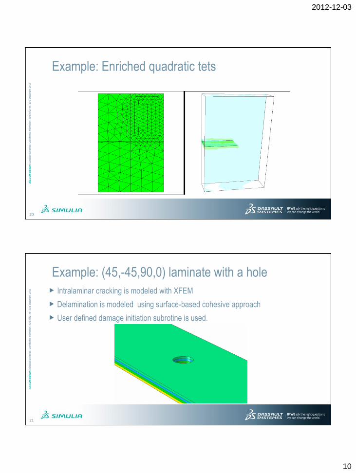
20
Example: Enriched quadratic tets
3DS
.CO
M/S
IMU
LIA
© D
assa
ult S
ystè
mes
| C
onfid
entia
l Inf
orm
atio
n | 1
2/3/
2012
| re
f.: 3
DS
_Doc
umen
t_20
12
21
Example: (45,-45,90,0) laminate with a hole
Intralaminar cracking is modeled with XFEM
Delamination is modeled using surface-based cohesive approach
User defined damage initiation subrotine is used.

2012-12-03
11
3DS
.CO
M/S
IMU
LIA
© D
assa
ult S
ystè
mes
| C
onfid
entia
l Inf
orm
atio
n | 1
2/3/
2012
| re
f.: 3
DS
_Doc
umen
t_20
12
22
Example: XFEM-based Low Cycle Fatigue
Based on linear elastic fracture mechanics approach
Governed by Paris law
Works within the framework of direct cyclic procedure
Assumes a pre-existing crack according to the accepted aero-industry practice The crack can then grow along an arbitrary path under cyclic fatigue loading
Can follow a static procedure where over-loading causes a crack nucleation
4
3
cGc
dN
da
3DS
.CO
M/S
IMU
LIA
© D
assa
ult S
ystè
mes
| C
onfid
entia
l Inf
orm
atio
n | 1
2/3/
2012
| re
f.: 3
DS
_Doc
umen
t_20
12
23
Example: Isotropic plate with a hole
A static loading is applied to cause a crack nucleation
Next, a periodic low cycle fatigue loading is applied

2012-12-03
12
3DS
.CO
M/S
IMU
LIA
© D
assa
ult S
ystè
mes
| C
onfid
entia
l Inf
orm
atio
n | 1
2/3/
2012
| re
f.: 3
DS
_Doc
umen
t_20
12
29
Example: Three point bending of AFS
Aluminum Foam Sandwich
Type Length Width Skin
Thickness Core Thickness Die Span
Core
Material
Skin
Material
A 300 30 0.5 10 250 Al Foam AL 3003
B 300 30 3 30 250 Al Foam AL 3003
C 300 30 6 10 250 Al Foam AL 3003
skin
core
length
width
3DS
.CO
M/S
IMU
LIA
© D
assa
ult S
ystè
mes
| C
onfid
entia
l Inf
orm
atio
n | 1
2/3/
2012
| re
f.: 3
DS
_Doc
umen
t_20
12
30
Example: Three point bending of AFS
FE Model (QTR Model)
Type Length Width Skim
Thickness Core Thickness Die Span
Core
Material
Skin
Material
A 300 30 0.5 10 250 Al Foam AL 3003
B 300 30 3 30 250 Al Foam AL 3003
C 300 30 6 10 250 Al Foam AL 3003
A B C
2012-12-03
13
3DS
.CO
M/S
IMU
LIA
© D
assa
ult S
ystè
mes
| C
onfid
entia
l Inf
orm
atio
n | 1
2/3/
2012
| re
f.: 3
DS
_Doc
umen
t_20
12
31
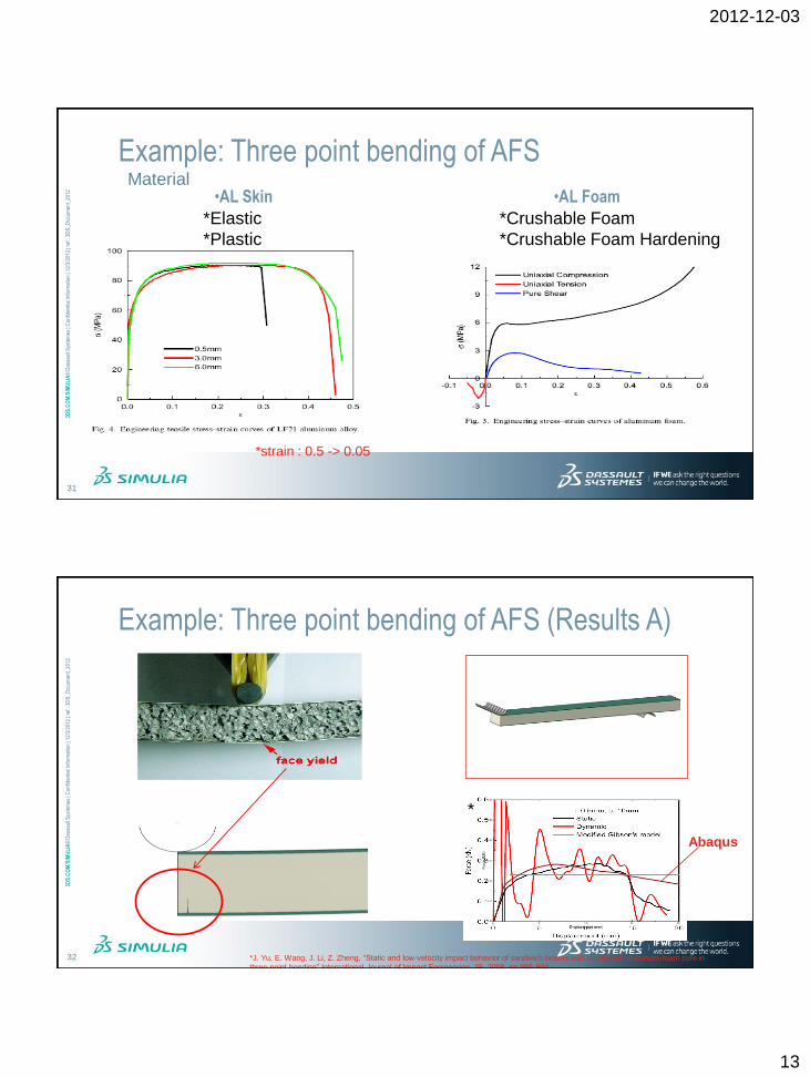
Example: Three point bending of AFS
•AL Skin •AL Foam
*strain : 0.5 -> 0.05
*Elastic
*Plastic
*Crushable Foam
*Crushable Foam Hardening
Material
3DS
.CO
M/S
IMU
LIA
© D
assa
ult S
ystè
mes
| C
onfid
entia
l Inf
orm
atio
n | 1
2/3/
2012
| re
f.: 3
DS
_Doc
umen
t_20
12
32
Example: Three point bending of AFS (Results A)
*J. Yu, E. Wang, J. Li, Z. Zheng, “Static and low-velocity impact behavior of sandwich beams with closed-cell aluminum-foam core in
three-point bending” International Journal of Impact Engineering, 35, 2008, pp 885-894
*
Abaqus

2012-12-03
14
3DS
.CO
M/S
IMU
LIA
© D
assa
ult S
ystè
mes
| C
onfid
entia
l Inf
orm
atio
n | 1
2/3/
2012
| re
f.: 3
DS
_Doc
umen
t_20
12
33
Example: Three point bending of AFS (Results B)
Abaqus
*J. Yu, E. Wang, J. Li, Z. Zheng, “Static and low-velocity impact behavior of sandwich beams with closed-cell aluminum-foam core in
three-point bending” International Journal of Impact Engineering, 35, 2008, pp 885-894
*
3DS
.CO
M/S
IMU
LIA
© D
assa
ult S
ystè
mes
| C
onfid
entia
l Inf
orm
atio
n | 1
2/3/
2012
| re
f.: 3
DS
_Doc
umen
t_20
12
34
Example: Three point bending of AFS (Results C)
Abaqus
*J. Yu, E. Wang, J. Li, Z. Zheng, “Static and low-velocity impact behavior of sandwich beams with closed-cell aluminum-foam core in
three-point bending” International Journal of Impact Engineering, 35, 2008, pp 885-894
*

2012-12-03
15
3DS
.CO
M/S
IMU
LIA
© D
assa
ult S
ystè
mes
| C
onfid
entia
l Inf
orm
atio
n | 1
2/3/
2012
| re
f.: 3
DS
_Doc
umen
t_20
12
35
Key features Allows moving and stationary cracks
Works with VCCT and cohesive elements
Supports low-cycle fatigue
Comprehensive modeling and visualization
Benefit Mesh-independent crack modeling
Summary
35