Embed Size (px)
Citation preview

Knorr-Bremse GroupKnorr-Bremse GroupKnorr-Bremse Group
14th CMG Meeting, PURISeptember 16, 2014
Wheel Slide Protection Device
Rajiv Agarwal
Knorr-Bremse Group Dateiname hier eintragen
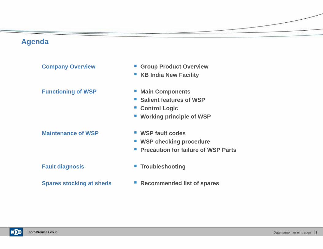
Agenda
│2
Company Overview
Functioning of WSP
Maintenance of WSP
Fault diagnosis
Spares stocking at sheds
� Group Product Overview� KB India New Facility
� Main Components� Salient features of WSP� Control Logic� Working principle of WSP
� WSP fault codes� WSP checking procedure� Precaution for failure of WSP Parts
� Troubleshooting
� Recommended list of spares

Knorr-Bremse Group
Knorr - Bremse
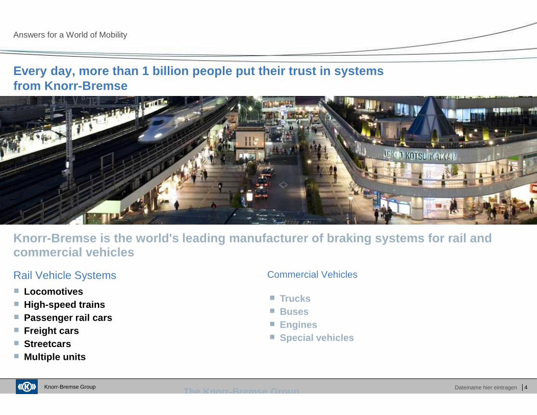
Every day, more than 1 billion people put their tru st in systems from Knorr-Bremse
Answer for a world of mobility
Knorr-Bremse Group Dateiname hier eintragenThe Knorr -Bremse Group
Every day, more than 1 billion people put their tru st in systemsfrom Knorr-Bremse
Answers for a World of Mobility
│4
Knorr-Bremse is the world's leading manufacturer of braking systems for rail and commercial vehicles
Rail Vehicle Systems� Locomotives� High-speed trains� Passenger rail cars� Freight cars� Streetcars� Multiple units
Commercial Vehicles
� Trucks� Buses� Engines� Special vehicles
Knorr-Bremse Group Dateiname hier eintragenThe Knorr -Bremse Group
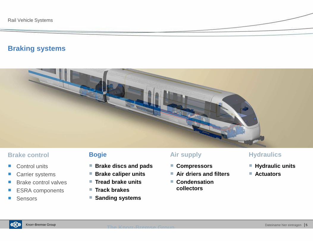
Braking systems
Rail Vehicle Systems
│5
� Control units
� Carrier systems� Brake control valves
� ESRA components� Sensors
Brake control Bogie Air supply Hydraulics
� Brake discs and pads� Brake caliper units� Tread brake units� Track brakes� Sanding systems
� Compressors� Air driers and filters� Condensation
collectors
� Hydraulic units� Actuators
Knorr-Bremse Group Dateiname hier eintragenThe Knorr -Bremse Group
On-board systems
Rail Vehicle Systems
│6
Off-trainOn-train
� Door systems
� Air-conditioning systems� Power supply
� Windscreen wipers� Information systems
� Driver information systems
� Platform screen door systems
� Train safety systems� Signalling systems
� Passenger informationsystems
� Drive simulators
Knorr-Bremse Group Dateiname hier eintragen
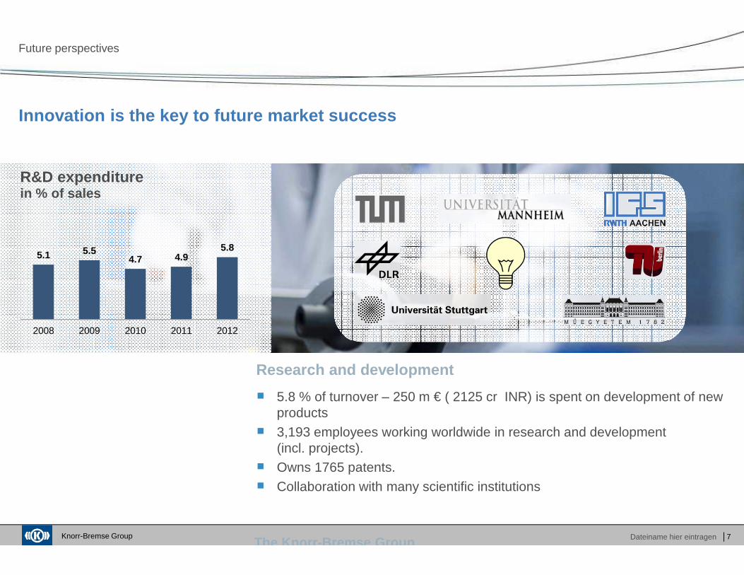
� 5.8 % of turnover – 250 m € ( 2125 cr INR) is spent on development of new products
� 3,193 employees working worldwide in research and development(incl. projects).
� Owns 1765 patents.
� Collaboration with many scientific institutions
The Knorr -Bremse Group
Innovation is the key to future market success
Future perspectives
Research and development
│7
R&D expenditurein % of sales
5.1 5.54.7 4.9
5.8
2008 2009 2010 2011 2012
Knorr-Bremse Group Dateiname hier eintragen
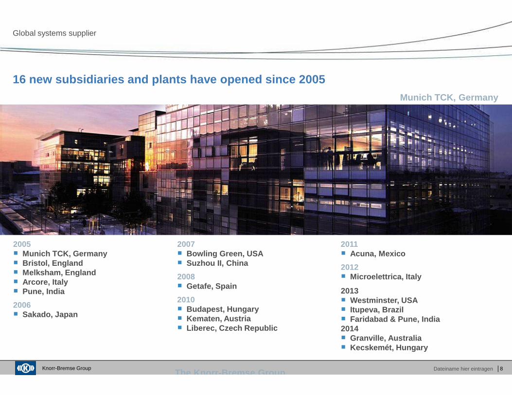
2007� Bowling Green, USA� Suzhou II, China
2008� Getafe, Spain
2010� Budapest, Hungary� Kematen, Austria� Liberec, Czech Republic
2005� Munich TCK, Germany� Bristol, England� Melksham, England� Arcore, Italy� Pune, India
2006� Sakado, Japan
The Knorr -Bremse Group
16 new subsidiaries and plants have opened since 20 05
Global systems supplier
│8
Munich TCK, Germany
2011� Acuna, Mexico
2012� Microelettrica, Italy
2013 � Westminster, USA� Itupeva, Brazil� Faridabad & Pune, India2014� Granville, Australia� Kecskemét, Hungary
Knorr-Bremse Group Dateiname hier eintragen │9
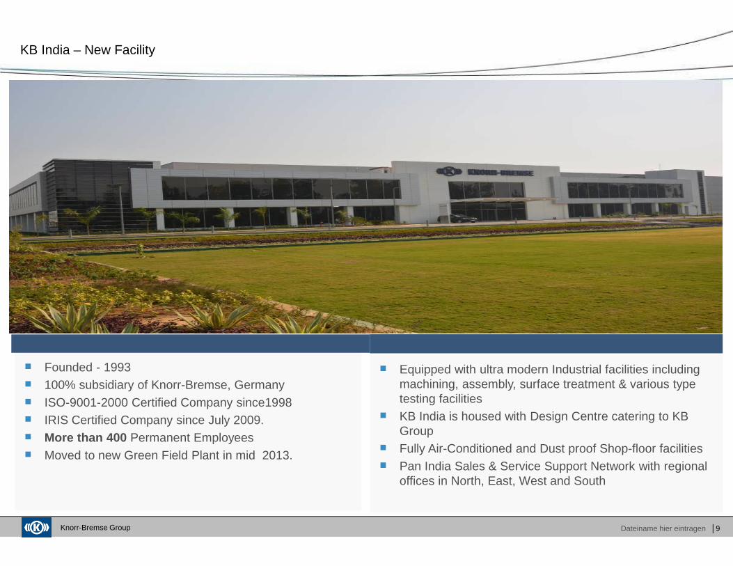
� Founded - 1993� 100% subsidiary of Knorr-Bremse, Germany
� ISO-9001-2000 Certified Company since1998� IRIS Certified Company since July 2009.� More than 400 Permanent Employees
� Moved to new Green Field Plant in mid 2013.
� Equipped with ultra modern Industrial facilities including machining, assembly, surface treatment & various type testing facilities
� KB India is housed with Design Centre catering to KB Group
� Fully Air-Conditioned and Dust proof Shop-floor facilities
� Pan India Sales & Service Support Network with regional offices in North, East, West and South
KB India – New Facility
Knorr-Bremse Group Dateiname hier eintragen │10
KB India
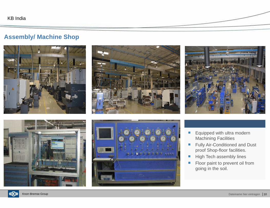
Assembly/ Machine Shop
� Equipped with ultra modern Machining Facilities
� Fully Air-Conditioned and Dust proof Shop-floor facilities.
� High Tech assembly lines
� Floor paint to prevent oil from going in the soil.
Knorr-Bremse Group Dateiname hier eintragen
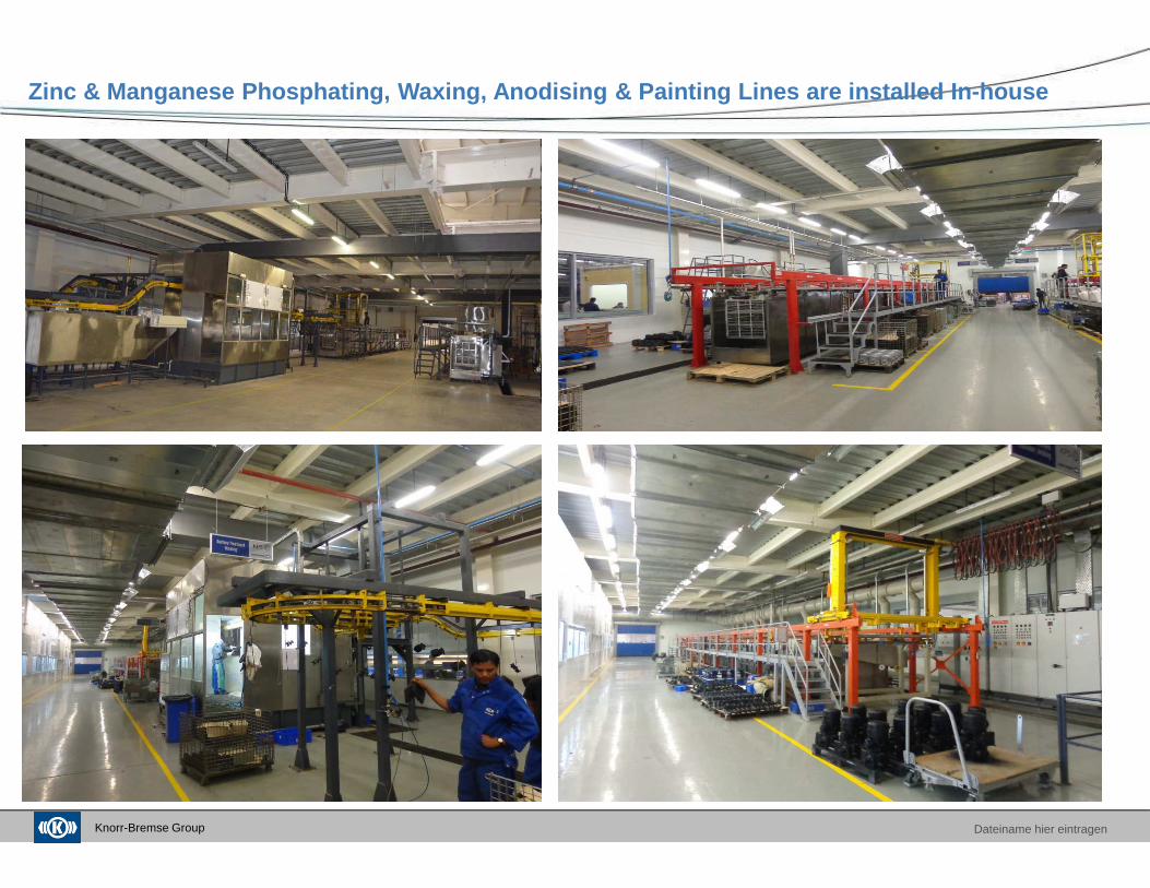
Zinc & Manganese Phosphating, Waxing, Anodising & Pa inting Lines are installed In-house
Knorr-Bremse Group Dateiname hier eintragen │12
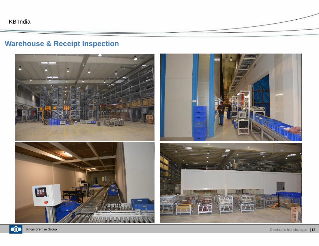
KB India
Warehouse & Receipt Inspection
Knorr-Bremse Group Dateiname hier eintragen
Agenda
│13
Company Overview
Functioning of WSP
Maintenance of WSP
Fault diagnosis
Spares stocking at sheds
� Group Product Overview� KB India New Facility
� Main Components� Salient features of WSP� Control Logic� Working principle of WSP
� WSP fault codes� WSP checking procedure� Precaution for failure of WSP Parts
� Troubleshooting
� Recommended list of spares
Knorr-Bremse Group Dateiname hier eintragen │14
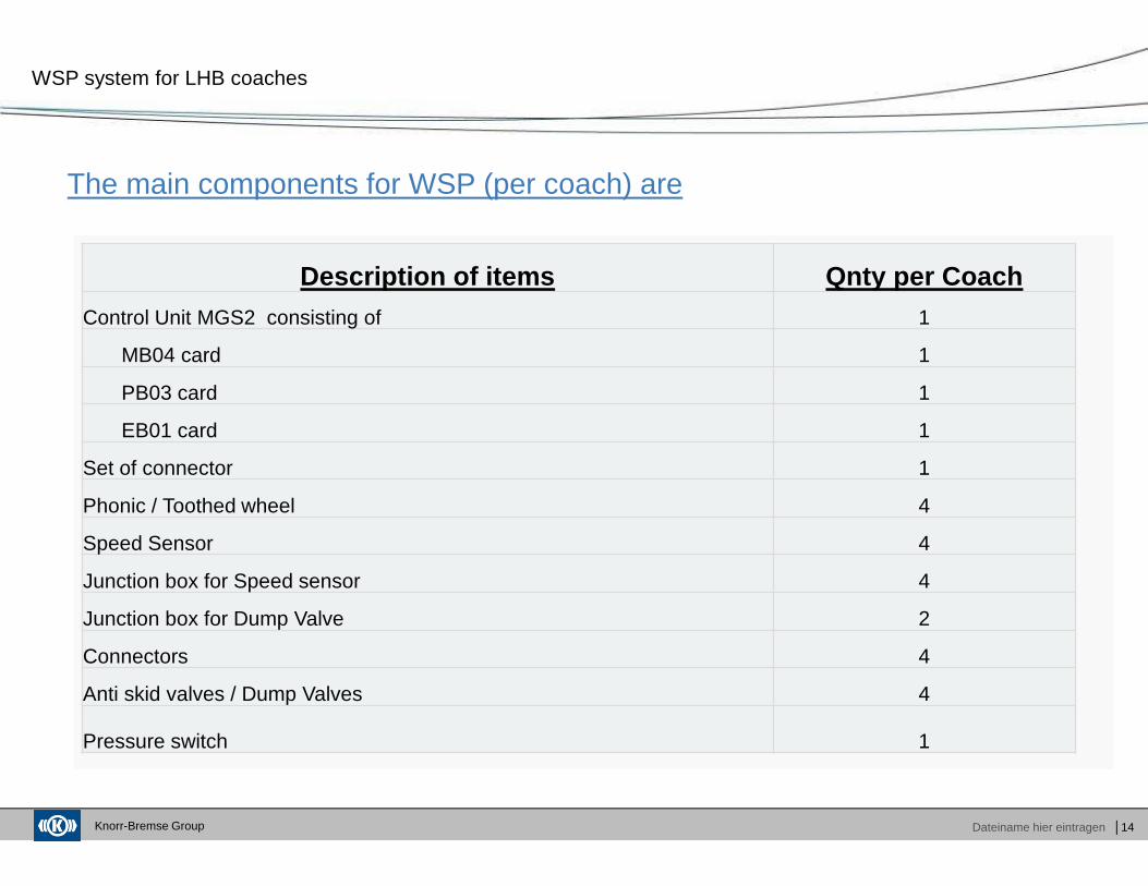
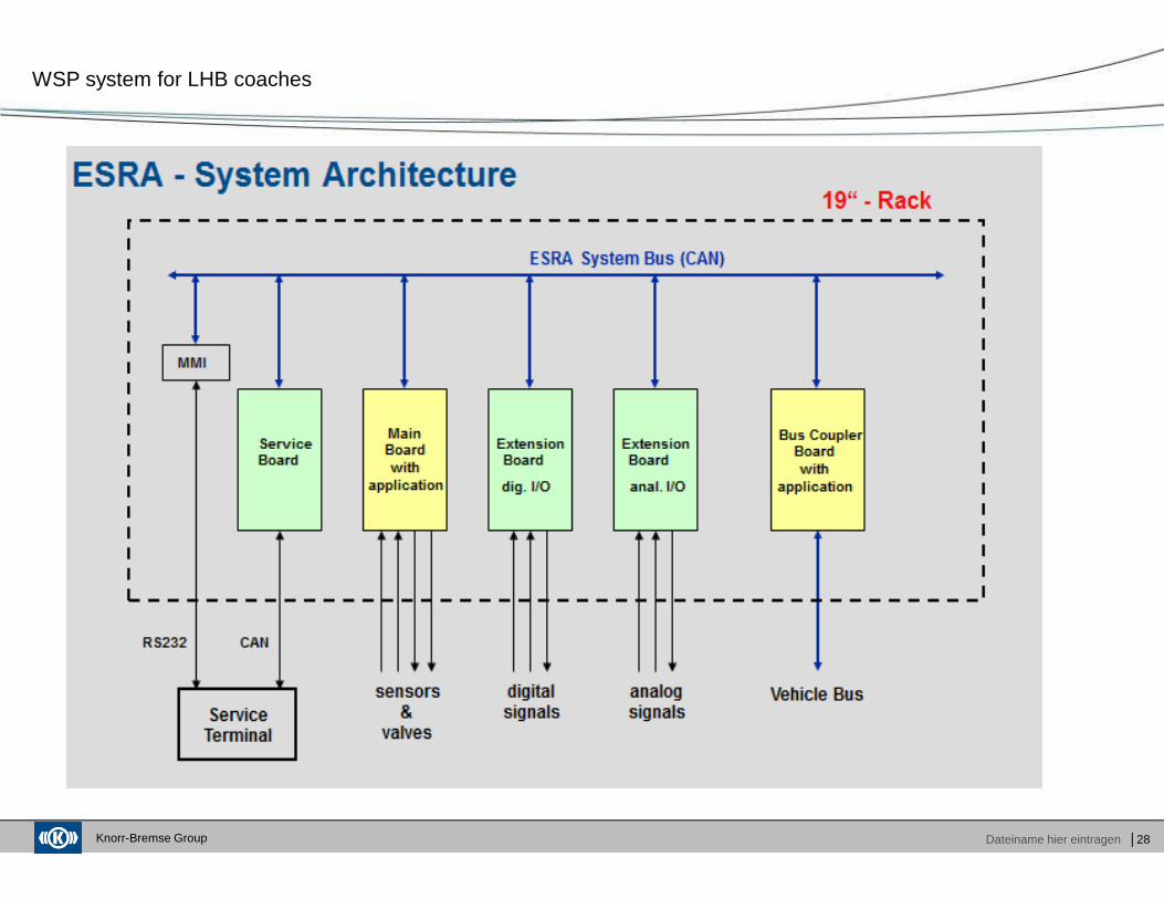
The main components for WSP (per coach) are
WSP system for LHB coaches
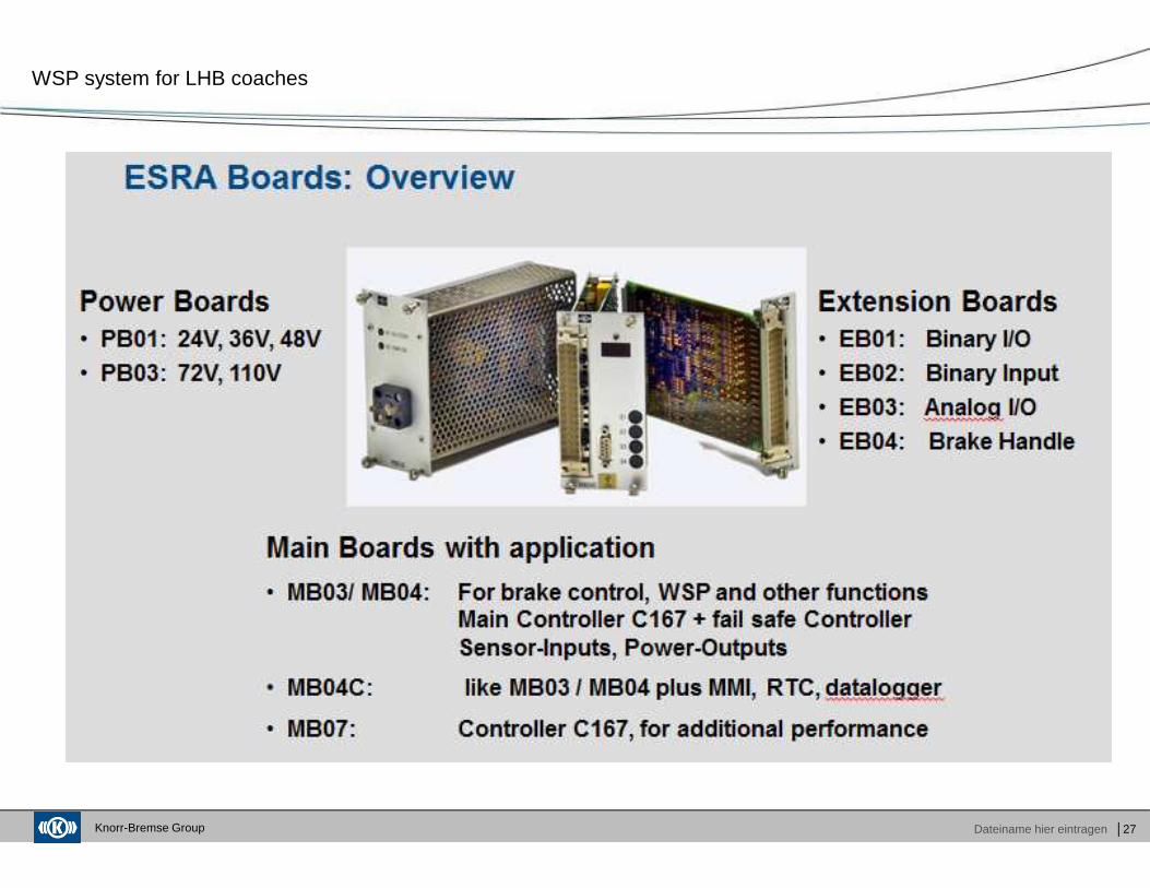
Description of items Qnty per Coach Control Unit MGS2 consisting of 1
MB04 card 1
PB03 card 1
EB01 card 1
Set of connector 1
Phonic / Toothed wheel 4
Speed Sensor 4
Junction box for Speed sensor 4
Junction box for Dump Valve 2
Connectors 4
Anti skid valves / Dump Valves 4
Pressure switch 1
Knorr-Bremse Group Dateiname hier eintragen │15
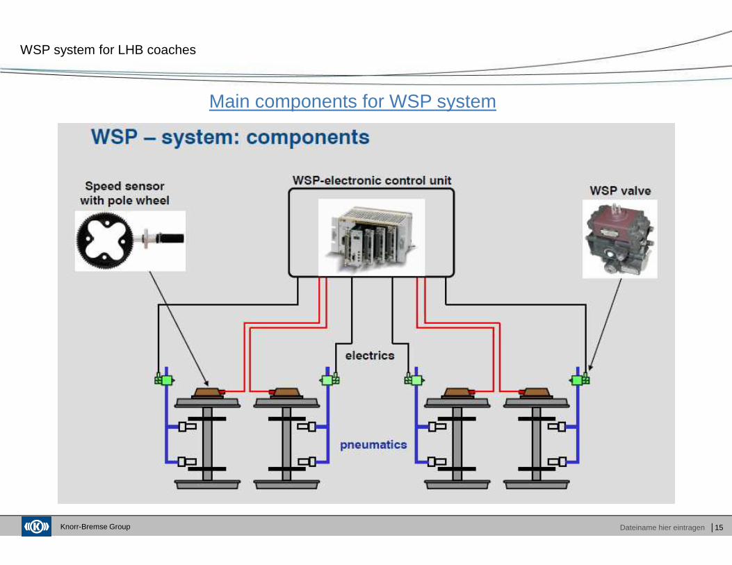
Main components for WSP system
WSP system for LHB coaches
Knorr-Bremse Group Dateiname hier eintragen │16
Salient features
WSP system for LHB coaches
� WSP device fitted to the vehicle has the role of reducing excessive wheel sliding resulting from
brake applications in situations where wheel / rail adhesion is temporarily impaired and prevents
wheels from locking / skidding.
� Safe protection of all wheelsets from locking even in the face of extremely low
adhesion due to wet leaves on the rails.
� Makes good use of the wheel / rail adhesion by regulating brake force.
� Allows short stopping distances by improving the mean coefficient of adhesion.
� Low air consumption
� Low power consumption
� Meets the requirements of UIC Code 541-05 and is listed in the UIC appendix L as approvedsystem.
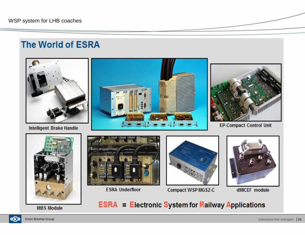
� The wheel slide protection (WSP) system has evolved from KNORR BREMSE’sproven experience in the field of microprocessor-based “wheel slide control". The control units arebased on Electronic System for Railway Applications (ESRA) technology.
Knorr-Bremse Group Dateiname hier eintragen │17
WSP system for LHB coaches
Knorr-Bremse Group Dateiname hier eintragen │18
WSP system for LHB coaches
Knorr-Bremse Group Dateiname hier eintragen │19
WSP system for LHB coaches
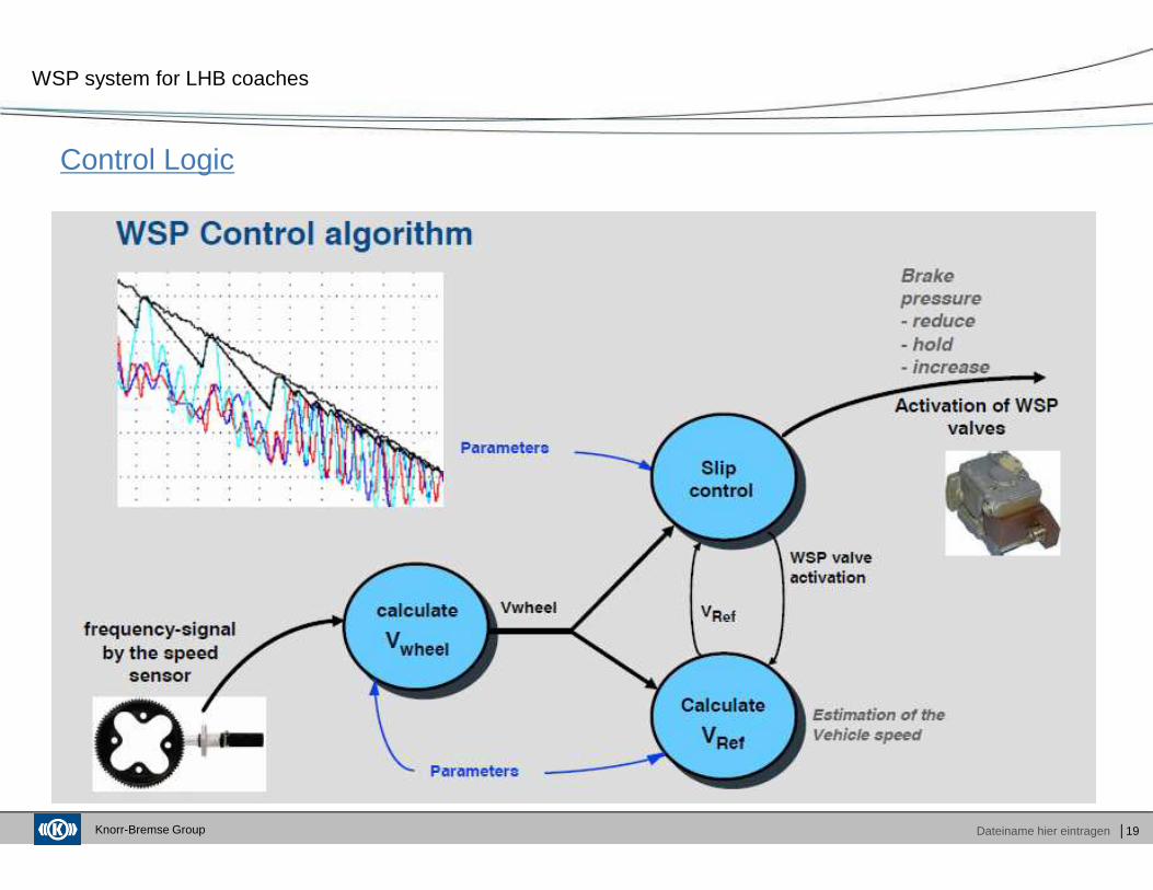
Control Logic
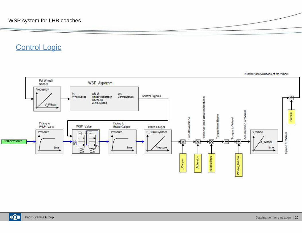
Knorr-Bremse Group Dateiname hier eintragen │20
WSP system for LHB coaches
Control Logic
Knorr-Bremse Group Dateiname hier eintragen │21
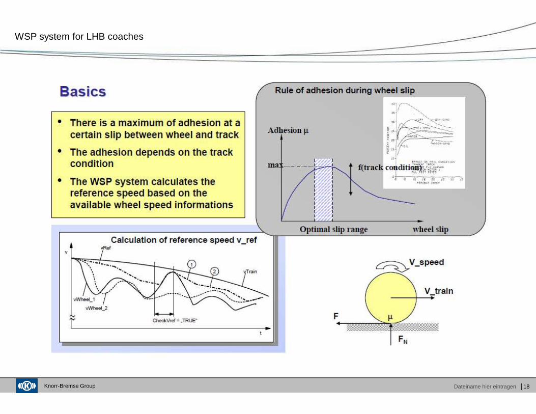
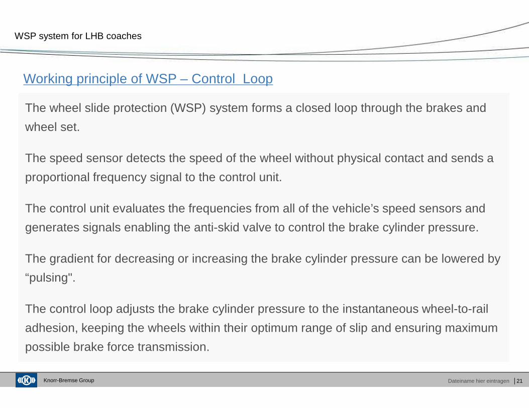
Working principle of WSP – Control Loop
WSP system for LHB coaches
The wheel slide protection (WSP) system forms a closed loop through the brakes and
wheel set.
The speed sensor detects the speed of the wheel without physical contact and sends a
proportional frequency signal to the control unit.
The control unit evaluates the frequencies from all of the vehicle’s speed sensors and
generates signals enabling the anti-skid valve to control the brake cylinder pressure.
The gradient for decreasing or increasing the brake cylinder pressure can be lowered by
“pulsing".
The control loop adjusts the brake cylinder pressure to the instantaneous wheel-to-rail
adhesion, keeping the wheels within their optimum range of slip and ensuring maximum
possible brake force transmission.
Knorr-Bremse Group Dateiname hier eintragen │22
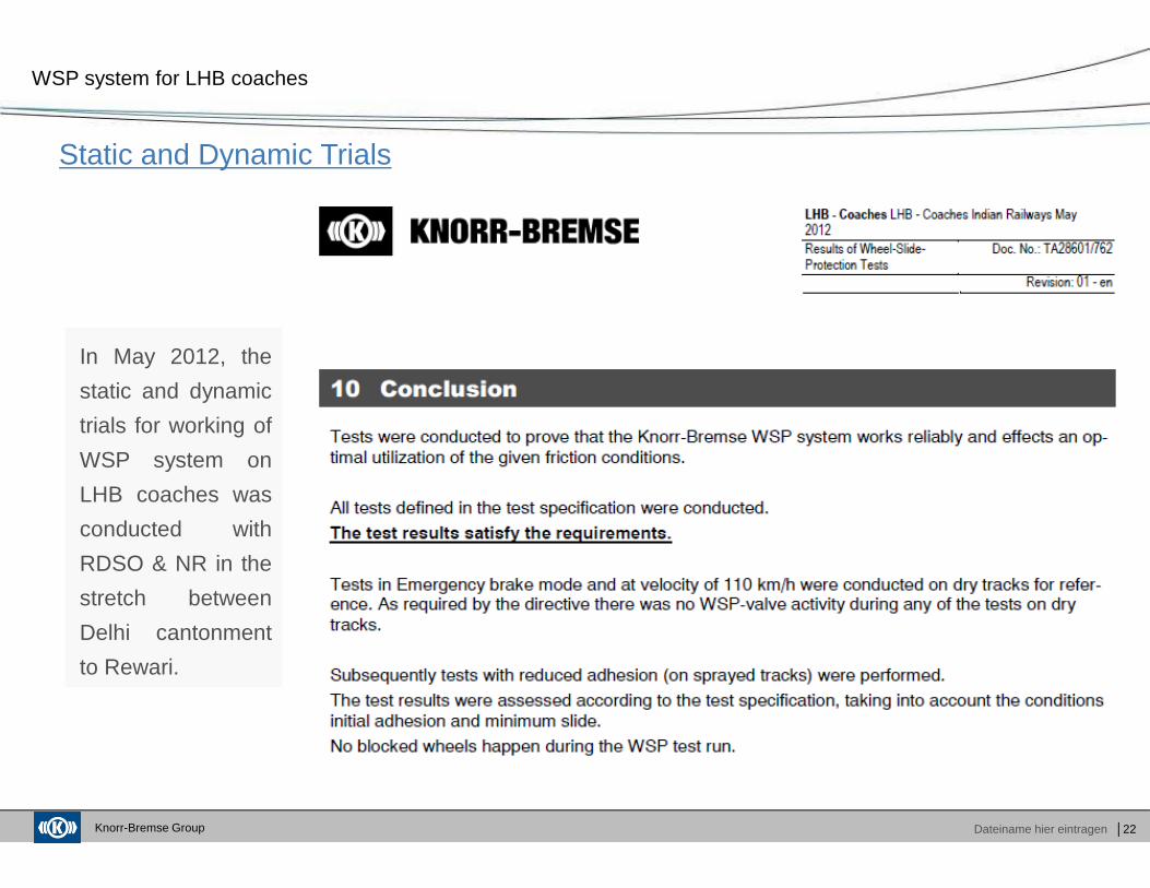
Static and Dynamic Trials
WSP system for LHB coaches
In May 2012, the
static and dynamic
trials for working of
WSP system on
LHB coaches was
conducted with
RDSO & NR in the
stretch between
Delhi cantonment
to Rewari.
Knorr-Bremse Group Dateiname hier eintragen │23
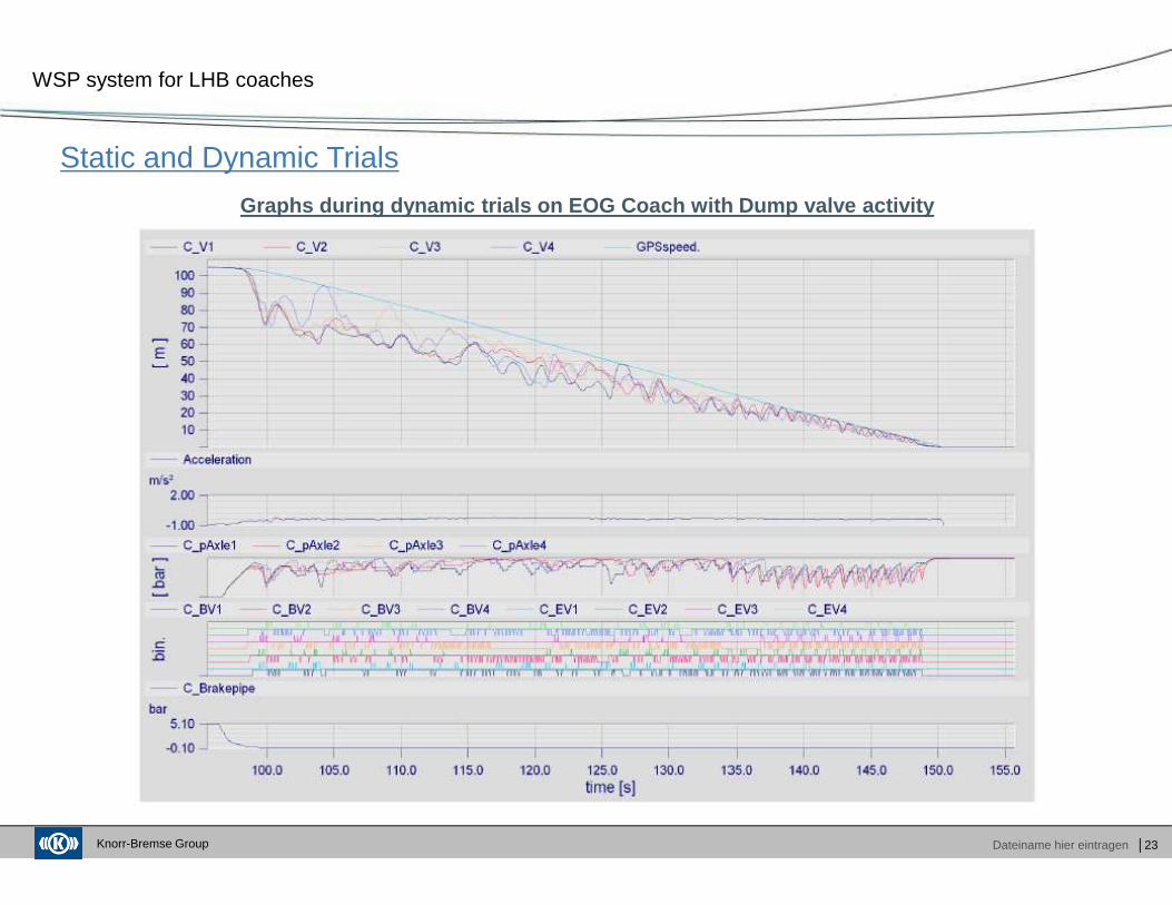
Static and Dynamic Trials
WSP system for LHB coaches
Graphs during dynamic trials on EOG Coach with Dump valve activity
Knorr-Bremse Group Dateiname hier eintragen │24
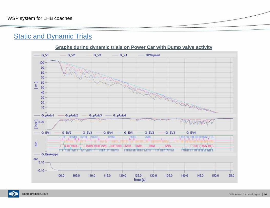
Static and Dynamic Trials
WSP system for LHB coaches
Graphs during dynamic trials on Power Car with Dump valve activity
Knorr-Bremse Group Dateiname hier eintragen │25
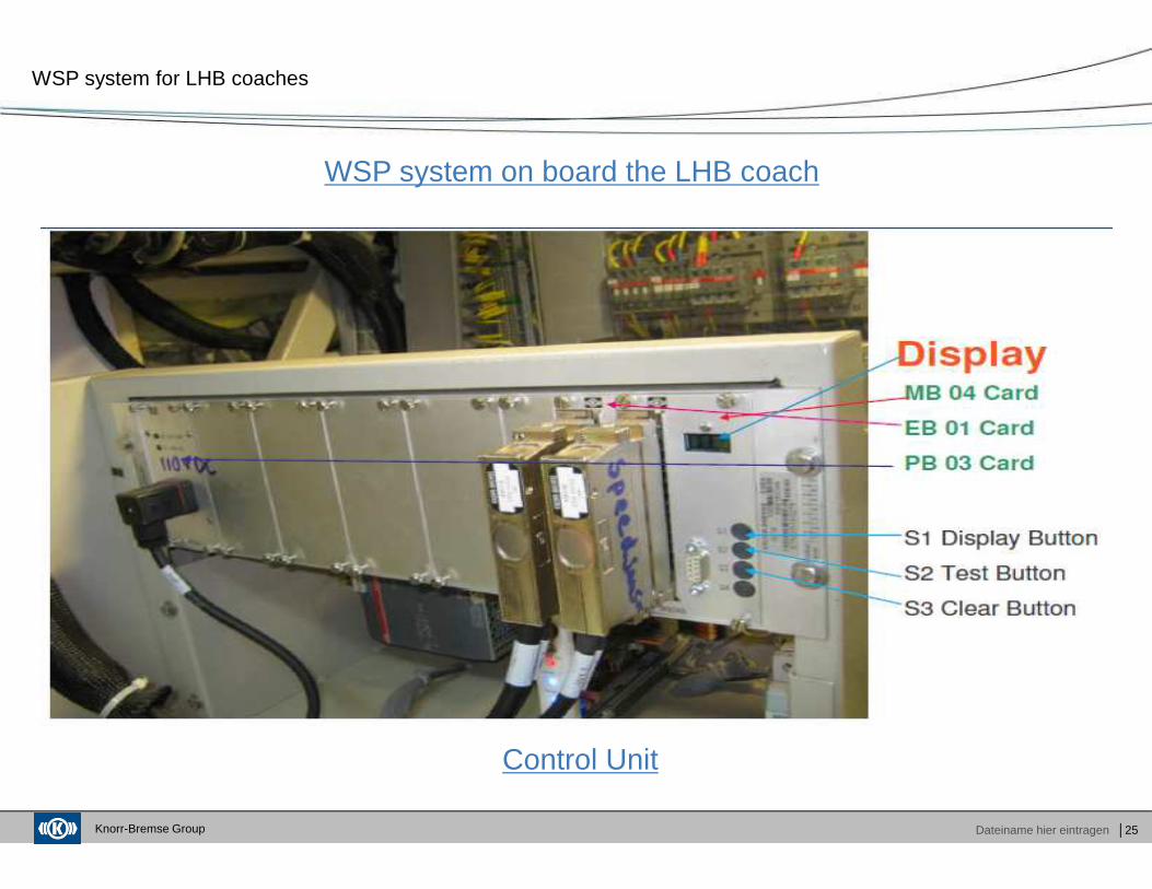
WSP system on board the LHB coach
WSP system for LHB coaches
Control Unit
Knorr-Bremse Group Dateiname hier eintragen │26
WSP system for LHB coaches
Knorr-Bremse Group Dateiname hier eintragen │27
WSP system for LHB coaches
Knorr-Bremse Group Dateiname hier eintragen │28
WSP system for LHB coaches
Knorr-Bremse Group Dateiname hier eintragen │29
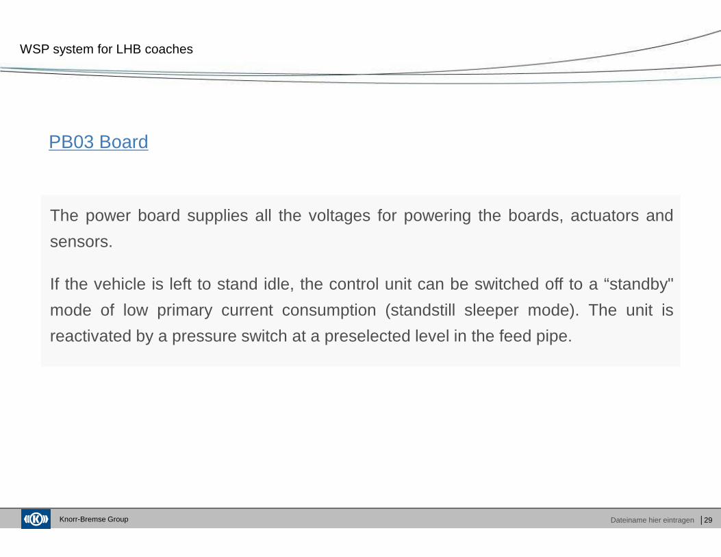
PB03 Board
WSP system for LHB coaches
The power board supplies all the voltages for powering the boards, actuators and
sensors.
If the vehicle is left to stand idle, the control unit can be switched off to a “standby"
mode of low primary current consumption (standstill sleeper mode). The unit is
reactivated by a pressure switch at a preselected level in the feed pipe.
Knorr-Bremse Group Dateiname hier eintragen │30
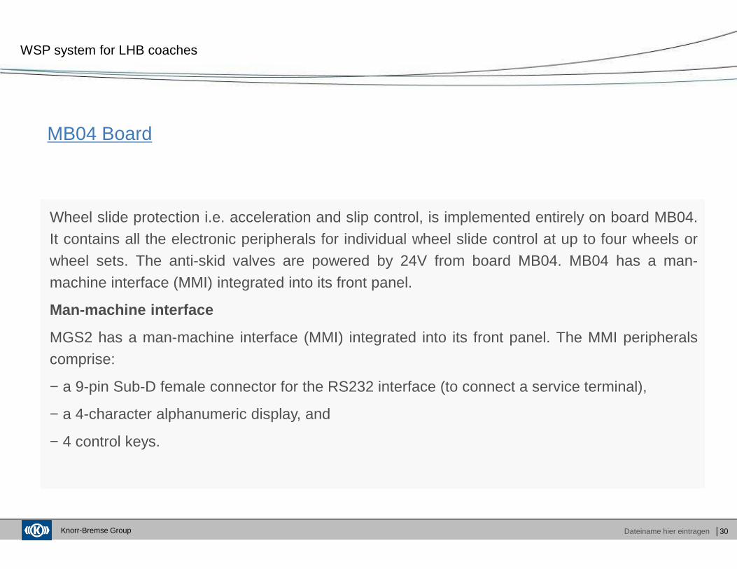
MB04 Board
WSP system for LHB coaches
Wheel slide protection i.e. acceleration and slip control, is implemented entirely on board MB04.It contains all the electronic peripherals for individual wheel slide control at up to four wheels orwheel sets. The anti-skid valves are powered by 24V from board MB04. MB04 has a man-machine interface (MMI) integrated into its front panel.
Man-machine interface
MGS2 has a man-machine interface (MMI) integrated into its front panel. The MMI peripheralscomprise:
− a 9-pin Sub-D female connector for the RS232 interface (to connect a service terminal),
− a 4-character alphanumeric display, and
− 4 control keys.
Knorr-Bremse Group Dateiname hier eintragen │31
EB01 Board
WSP system for LHB coaches
EB01 is an extension board in the MGS2 control unit. It provides digital inputs and outputs. It isalso utilized for supplementary functions such as door control.
Knorr-Bremse Group Dateiname hier eintragen │32
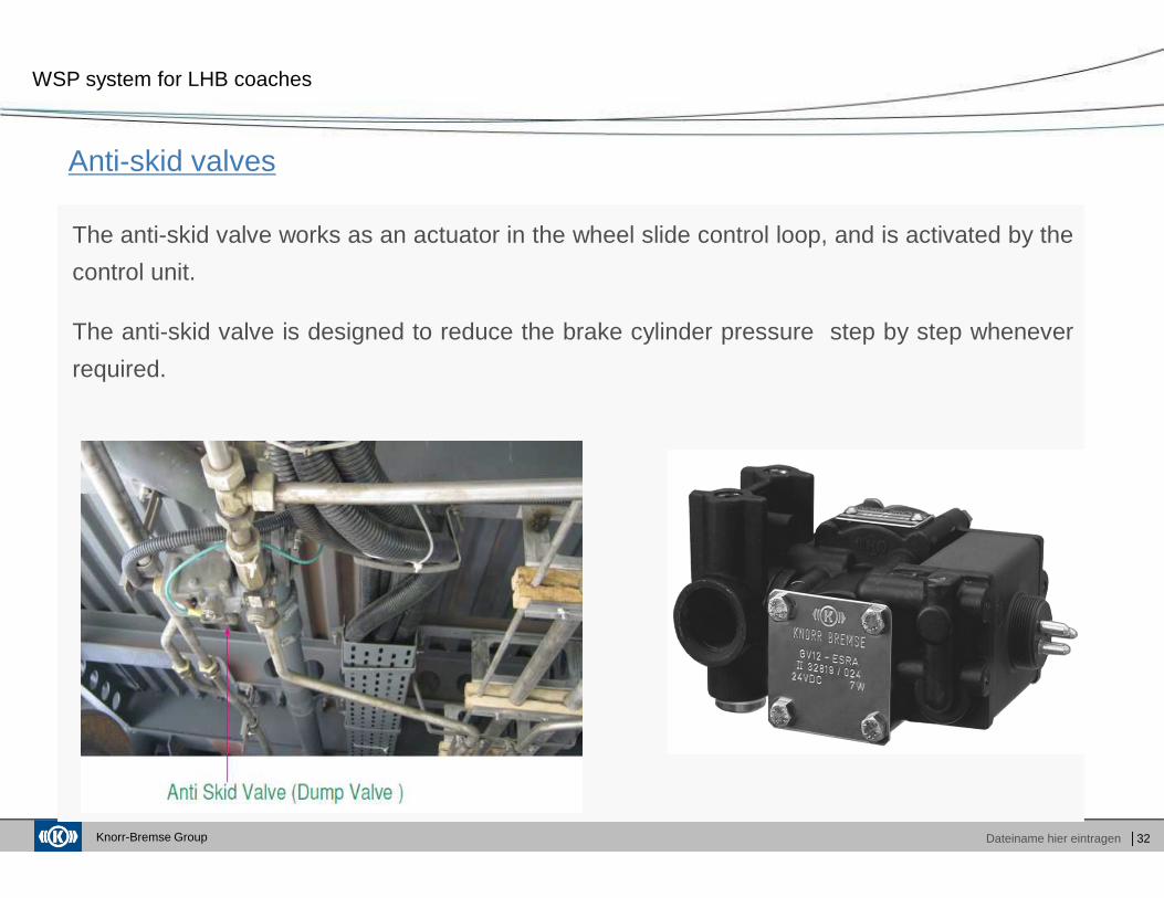
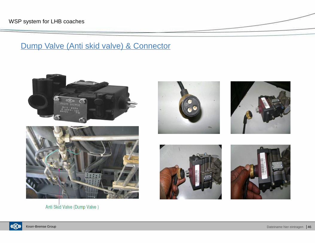
Anti-skid valves
WSP system for LHB coaches
The anti-skid valve works as an actuator in the wheel slide control loop, and is activated by the
control unit.
The anti-skid valve is designed to reduce the brake cylinder pressure step by step whenever
required.
Knorr-Bremse Group Dateiname hier eintragen │33
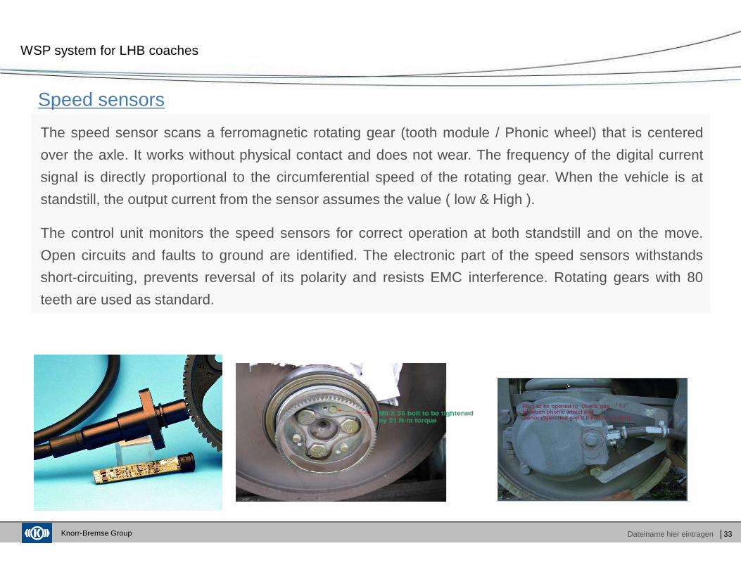
Speed sensors
WSP system for LHB coaches
The speed sensor scans a ferromagnetic rotating gear (tooth module / Phonic wheel) that is centered
over the axle. It works without physical contact and does not wear. The frequency of the digital current
signal is directly proportional to the circumferential speed of the rotating gear. When the vehicle is at
standstill, the output current from the sensor assumes the value ( low & High ).
The control unit monitors the speed sensors for correct operation at both standstill and on the move.
Open circuits and faults to ground are identified. The electronic part of the speed sensors withstands
short-circuiting, prevents reversal of its polarity and resists EMC interference. Rotating gears with 80
teeth are used as standard.
Knorr-Bremse Group Dateiname hier eintragen
Agenda
│34
Company Overview
Functioning of WSP
Maintenance of WSP
Fault diagnosis
Spares stocking at sheds
� Group Product Overview� KB India New Facility
� Main Components� Salient features of WSP� Control Logic� Working principle of WSP
� WSP fault codes� WSP checking procedure� Precaution for failure of WSP Parts
� Troubleshooting
� Recommended list of spares
Knorr-Bremse Group Dateiname hier eintragen │35
WSP Fault Codes
WSP system for LHB coaches
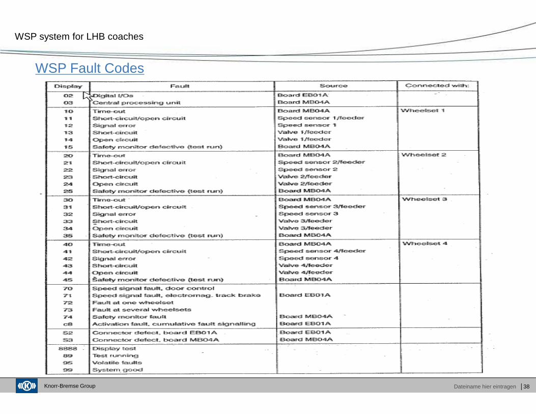
Display – 99 means System OK.
Display – 95 means System OK, but some previous fault codes has got logged (Volatile – can be
erased by pressing S3 button on MB 04 Card).
Display – 7201 means fault in one wheel set.
Display – 7301 means fault in several wheel set.
Display – 8888 Display Test (Shows in sequence of diagnosis / testing) .
Display – 89 Testing Mode (Dump Valve self testing in progress).
Display – 0301 means fault noted / sourced / related to MB 04 Card (Shows in sequence of
diagnosis).
Display – 0201 means fault noted / sourced / related to EB 01 Card (Shows in sequence of
diagnosis).
Knorr-Bremse Group Dateiname hier eintragen │36
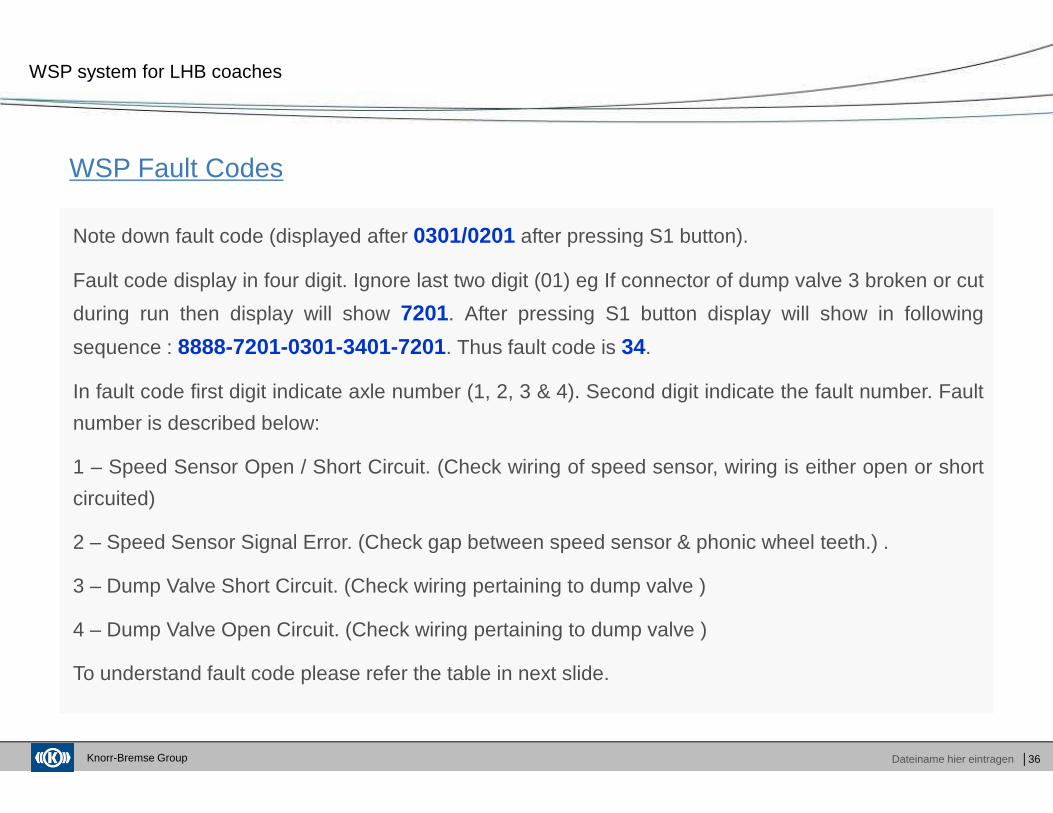
WSP Fault Codes
WSP system for LHB coaches
Note down fault code (displayed after 0301/0201 after pressing S1 button).
Fault code display in four digit. Ignore last two digit (01) eg If connector of dump valve 3 broken or cut
during run then display will show 7201. After pressing S1 button display will show in following
sequence : 8888-7201-0301-3401-7201. Thus fault code is 34.
In fault code first digit indicate axle number (1, 2, 3 & 4). Second digit indicate the fault number. Fault
number is described below:
1 – Speed Sensor Open / Short Circuit. (Check wiring of speed sensor, wiring is either open or short
circuited)
2 – Speed Sensor Signal Error. (Check gap between speed sensor & phonic wheel teeth.) .
3 – Dump Valve Short Circuit. (Check wiring pertaining to dump valve )
4 – Dump Valve Open Circuit. (Check wiring pertaining to dump valve )
To understand fault code please refer the table in next slide.
Knorr-Bremse Group Dateiname hier eintragen │37
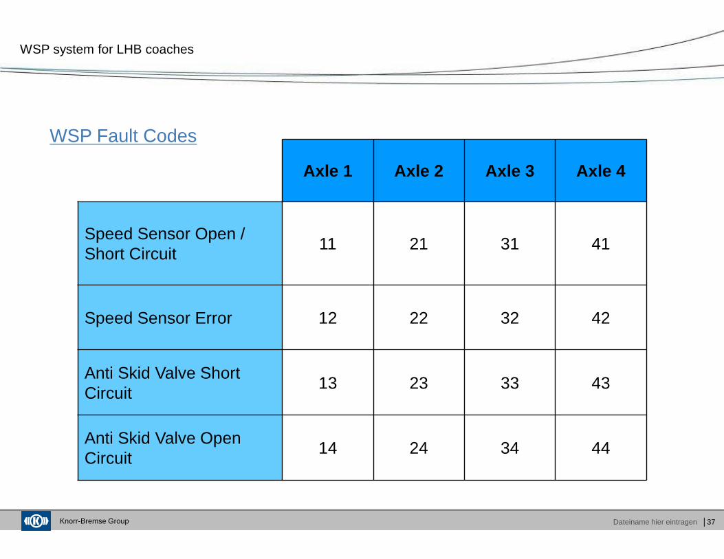
WSP Fault Codes
WSP system for LHB coaches
Axle 1 Axle 2 Axle 3 Axle 4
Speed Sensor Open / Short Circuit
11 21 31 41
Speed Sensor Error 12 22 32 42
Anti Skid Valve Short Circuit
13 23 33 43
Anti Skid Valve Open Circuit
14 24 34 44
Knorr-Bremse Group Dateiname hier eintragen │38
WSP Fault Codes
WSP system for LHB coaches
Knorr-Bremse Group Dateiname hier eintragen │39
WSP checking procedure at Sheds / Depots / Workshops
WSP system for LHB coaches
Check WSP display (in MB04 Card at WSP panel placed in power panel of coach) before start of
maintenance.
WSP display ‘99’ means system is healthy. Other testing need to be followed (Dump Valve Self Test
by pressing ‘S2’ switch), if required.
WSP display ‘95’ means present status is healthy but system has logged previous fault and system is
serviceable. To check the previous fault please follow following steps :
Press ‘S1’ switch display for less than 3 Sec. Display will show in following sequence : 8888-95-
7201(/7301)-0301-A1F101-A2F201-…..-95 . Note down the failure code coach wise and date wise.
Take corrective measure in respective areas.
Proceed with other testing (Dump Valve Self Test by pressing ‘S2’ switch).
DON’T press ‘S3’ switch (to clear volatile fault memory) and let the coach run with 95 code. But
ensure that the required repairs is done for the fault which is showing / logged.
Follow the same procedure in next maintenance or testing. Record & check if any new fault is logged.
Knorr-Bremse Group Dateiname hier eintragen │40
WSP checking procedure at Sheds / Depots / Workshops
WSP system for LHB coaches
WSP display ‘7201’ or ‘7301 ’ means there are some current fault logged in system. To check faults
follow these steps:
Press ‘S1’ switch for less than 3 sec. The display will show in following sequence : 8888-7201 (/7301)-
0301- A1F101-A2F201-…..-7201 (/7301). Note down the failure code coach wise and date wise in
log book. Rectify according to fault code (A1F1 , A2F2 etc.).
Check the display whether 95 or 7201 (/7301). If 95 then proceed with further testing. If fault still exists
then rectify accordingly.
DON’T press ‘S3’ switch (to clear volatile fault memory) and let the coach run with 95 code. But ensure
that the required repairs is done for the fault which is showing.
Follow the same procedure in next maintenance or testing. Record and check if any new fault is
showing / logged.
Note : If ‘S1’ switch pressed for more than 3 sec then fault code will be displayed one by one by
pressing S1 each time.
Knorr-Bremse Group Dateiname hier eintragen │41
Precautions for reduction of Card Failures
WSP system for LHB coaches
Card failures mostly take place because of the following
1) High surges in the electric power supply especially because of welding & other equipment's which
draw very high current. Ensure electric supply to control unit is off while using such equipment's.
2) Disconnecting cards when power is ON & display is “LIVE”. Ensure fuse 63 & 65 are removed so
that no power supply goes to control unit before removing, loosening or replacing any of the cards in
the board.
3) In case download is being taken by using an additional SB03A ( part no STN28328) service board /
can connector, ensure power is off or fuse is removed before fitting or removing the Can card (In case
Railways uses the ST03 Software).
4) Short circuit in the control panel or connecting wrong wires during repair of any other equipment in
the control panel which has relevance to control unit provided by Knorr Bremse. Railway electricians
to take precautions.
5) Loose connections result into sparking & short circuit of card. Railway electricians to ensure proper
connections.
Knorr-Bremse Group Dateiname hier eintragen │42
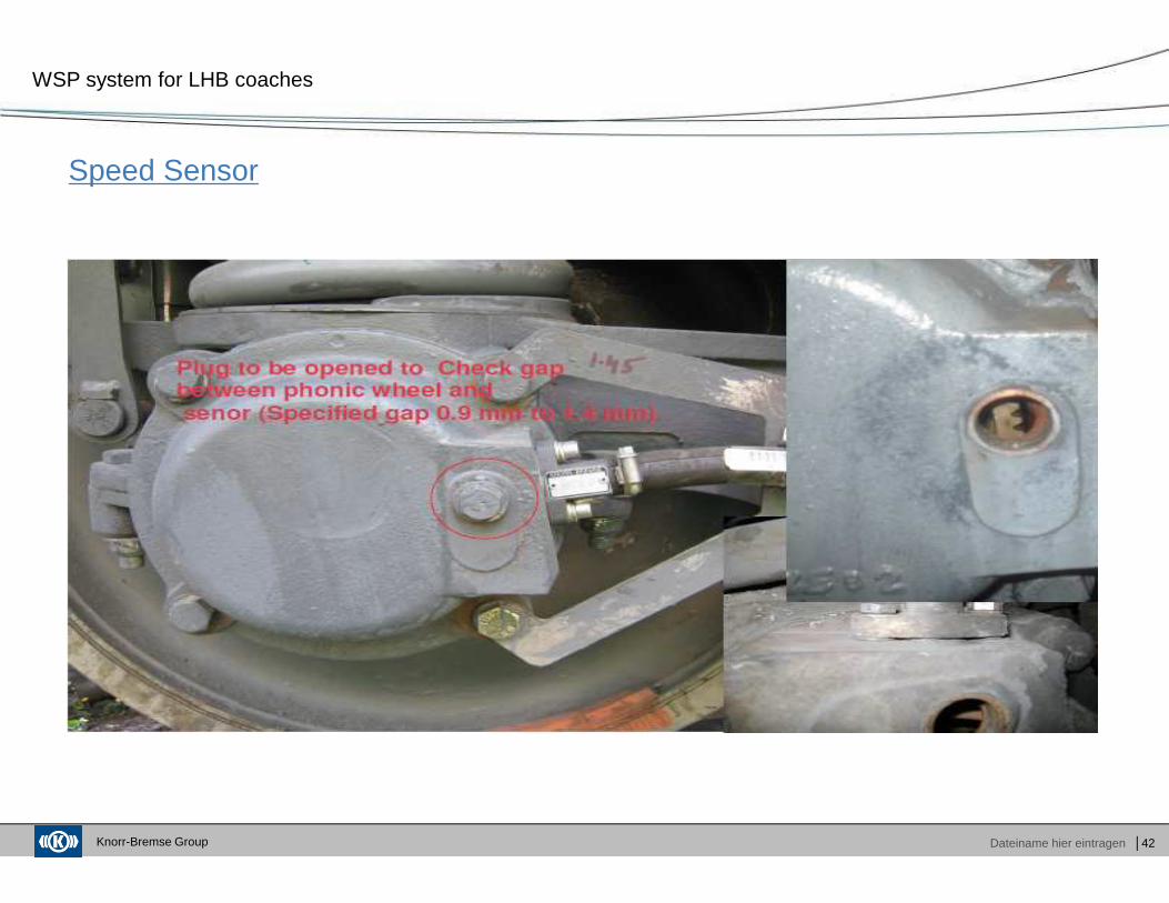
Speed Sensor
WSP system for LHB coaches
Knorr-Bremse Group Dateiname hier eintragen │43
Precautions for reduction of Speed Sensor failures
WSP system for LHB coaches
In general the speed sensor Gap should be checked every quarter or whenever the fault 12,
22, 32, 42 is showing in the WSP display. It can be corrected by addition or removal of shims.
The gap has to be maintained between 0.9 mm to 1.4 mm.
In case of damage of the speed sensor, it needs to be replaced. It is not recommended to
repair the damaged sensor. Kindly use only Knorr make speed sensor. Other make of speed
sensors may not provide proper input for correct functioning of our WSP.
In case of open or short circuit of the speed sensor fault 11,21,31,41 will show in the display.
Kindly check the wirings & repair the same. If not repairable then replace.
Knorr-Bremse Group Dateiname hier eintragen │44
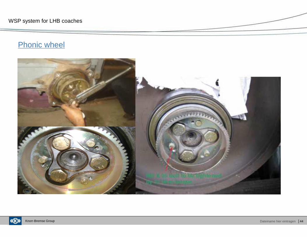
Phonic wheel
WSP system for LHB coaches
Knorr-Bremse Group Dateiname hier eintragen │45
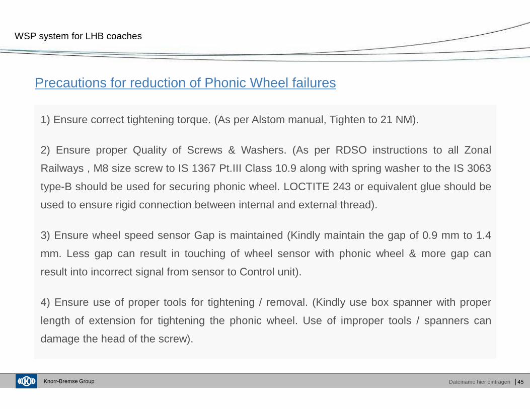
Precautions for reduction of Phonic Wheel failures
WSP system for LHB coaches
1) Ensure correct tightening torque. (As per Alstom manual, Tighten to 21 NM).
2) Ensure proper Quality of Screws & Washers. (As per RDSO instructions to all Zonal
Railways , M8 size screw to IS 1367 Pt.III Class 10.9 along with spring washer to the IS 3063
type-B should be used for securing phonic wheel. LOCTITE 243 or equivalent glue should be
used to ensure rigid connection between internal and external thread).
3) Ensure wheel speed sensor Gap is maintained (Kindly maintain the gap of 0.9 mm to 1.4
mm. Less gap can result in touching of wheel sensor with phonic wheel & more gap can
result into incorrect signal from sensor to Control unit).
4) Ensure use of proper tools for tightening / removal. (Kindly use box spanner with proper
length of extension for tightening the phonic wheel. Use of improper tools / spanners can
damage the head of the screw).
Knorr-Bremse Group Dateiname hier eintragen │46
Dump Valve (Anti skid valve) & Connector
WSP system for LHB coaches
Knorr-Bremse Group Dateiname hier eintragen │47
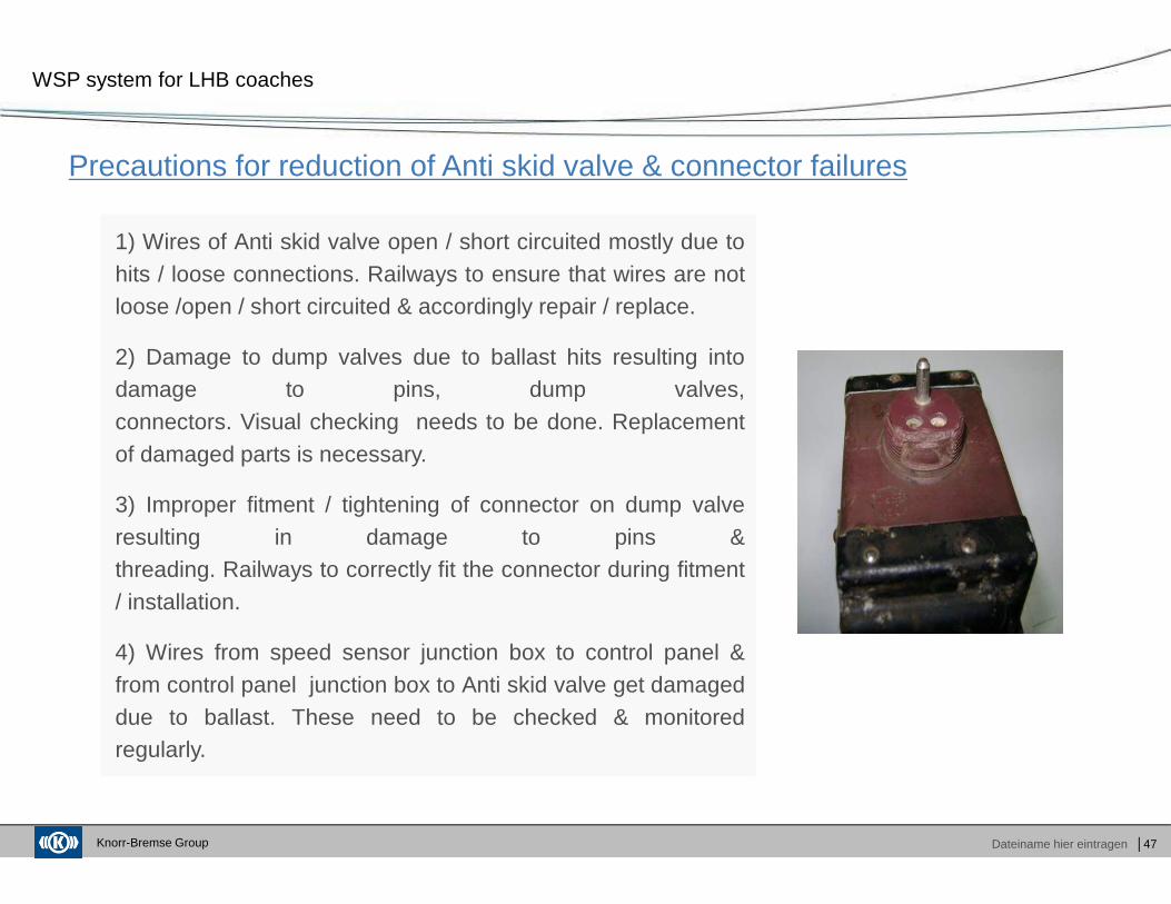
Precautions for reduction of Anti skid valve & connector failures
WSP system for LHB coaches
1) Wires of Anti skid valve open / short circuited mostly due tohits / loose connections. Railways to ensure that wires are notloose /open / short circuited & accordingly repair / replace.
2) Damage to dump valves due to ballast hits resulting intodamage to pins, dump valves,connectors. Visual checking needs to be done. Replacementof damaged parts is necessary.
3) Improper fitment / tightening of connector on dump valveresulting in damage to pins &threading. Railways to correctly fit the connector during fitment/ installation.
4) Wires from speed sensor junction box to control panel &from control panel junction box to Anti skid valve get damageddue to ballast. These need to be checked & monitoredregularly.
Knorr-Bremse Group Dateiname hier eintragen
Agenda
│48
Company Overview
Functioning of WSP
Maintenance of WSP
Fault diagnosis
Spares stocking at sheds
� Group Product Overview� KB India New Facility
� Main Components� Salient features of WSP� Control Logic� Working principle of WSP
� WSP fault codes� WSP checking procedure� Precaution for failure of WSP Parts
� Troubleshooting
� Recommended list of spares

Knorr-Bremse Group Dateiname hier eintragen │49
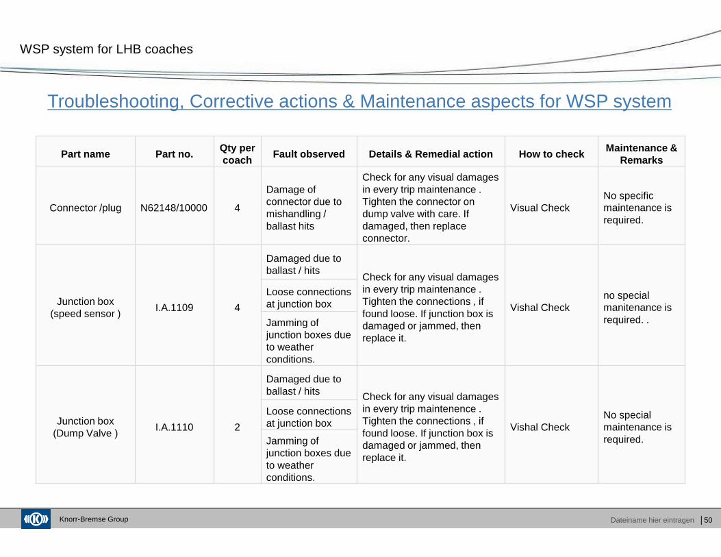
Troubleshooting, Corrective actions & Maintenance aspects for WSP system
WSP system for LHB coaches
Part name Part no.Qty. per
coachFault observed Details & Remedial action How to chec k
Maintenance & Remarks
Wheel speed sensor
II35456/20013 or
STN31450/205A18U
4
Damage of sensor due to ballast / hits
Check for any visual damages in every trip maintenance . Replace sensor.
There are two ways of Static testing 1. By a pole wheel simulator. 2. by pressing S2 (Self Test) on WSP control panel.
No specific maintenance is required.
Damage of sensor due to rubbing with phonic wheel
Ensure correct sensor gap on every quarterly schedule or when required. Also ensure phonic wheel is tightened properly, depending on extent of damage. Replace sensor when found damaged.
Dump valve / Anti Skid Valve
II34652/15024 4
Damage of valve due to hits / ballast
Check for any visual damages in every trip maintenance. Replace dump valve.
There are two ways of Static testing 1. By a pole wheel simulator. 2. by pressing S2 (Self Test) on WSP control panel.
Overhauling of Dump valve is recommended every 36 months (POH).
Damaged or loose connections to anti skid valve
Tighten connection, repair or replace wires as necessary.
Damaged / broken pins due to mishandling / ballast hits
Check for any visual damages in every trip maintenance . Tighten the connector on dump valve with care. If non repairable, then replace dump valve.
Knorr-Bremse Group Dateiname hier eintragen │50
Troubleshooting, Corrective actions & Maintenance aspects for WSP system
WSP system for LHB coaches
Part name Part no.Qty per coach
Fault observed Details & Remedial action How to chec kMaintenance &
Remarks
Connector /plug N62148/10000 4
Damage of connector due to mishandling / ballast hits
Check for any visual damages in every trip maintenance . Tighten the connector on dump valve with care. If damaged, then replace connector.
Visual CheckNo specific maintenance is required.
Junction box (speed sensor )
I.A.1109 4
Damaged due to ballast / hits
Check for any visual damages in every trip maintenance . Tighten the connections , if found loose. If junction box is damaged or jammed, then replace it.
Vishal Checkno special manitenance is required. .
Loose connections at junction box
Jamming of junction boxes due to weather conditions.
Junction box (Dump Valve )
I.A.1110 2
Damaged due to ballast / hits Check for any visual damages
in every trip maintenence . Tighten the connections , if found loose. If junction box is damaged or jammed, then replace it.
Vishal CheckNo special maintenance is required.
Loose connections at junction box
Jamming of junction boxes due to weather conditions.
Knorr-Bremse Group Dateiname hier eintragen │51
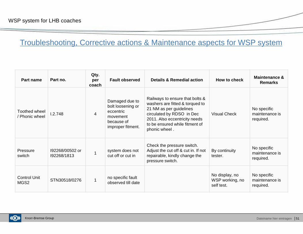
Troubleshooting, Corrective actions & Maintenance aspects for WSP system
WSP system for LHB coaches
Part name Part no.Qty. per
coachFault observed Details & Remedial action How to chec k Maintenance &
Remarks
Toothed wheel / Phonic wheel
I.2.748 4
Damaged due to bolt loosening or eccentric movement because of improper fitment.
Railways to ensure that bolts & washers are fitted & torqued to 21 NM as per guidelines circulated by RDSO in Dec 2011. Also eccentricity needs to be ensured while fitment of phonic wheel .
Visual CheckNo specific maintenance is required.
Pressure switch
I92268/00502 or I92268/1813
1system does not cut off or cut in
Check the pressure switch. Adjust the cut off & cut in. If not repairable, kindly change the pressure switch.
By continuity tester.
No specific maintenance is required.
Control Unit MGS2
STN30518/0276 1no specific fault observed till date
No display, no WSP working, no self test.
No specific maintenance is required.
Knorr-Bremse Group Dateiname hier eintragen │52
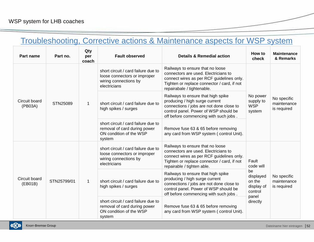
Troubleshooting, Corrective actions & Maintenance aspects for WSP system
WSP system for LHB coaches
Part name Part no.Qty per
coachFault observed Details & Remedial action
How to check
Maintenance & Remarks
Circuit board (PB03A)
STN25089 1
short circuit / card failure due to loose connectors or improper wiring connections by electricians
Railways to ensure that no loose connectors are used. Electricians to connect wires as per RCF guidelines only. Tighten or replace connector / card, if not repairabale / tightenable.
No power supply to WSP system
No specific maintenance is required
short circuit / card failure due to high spikes / surges
Railways to ensure that high spike producing / high surge current connections / jobs are not done close to control panel. Power of WSP should be off before commencing with such jobs .
short circuit / card failure due to removal of card during power ON condition of the WSP system
Remove fuse 63 & 65 before removing any card from WSP system ( control Unit).
Circuit board (EB01B)
STN25799/01 1
short circuit / card failure due to loose connectors or improper wiring connections by electricians
Railways to ensure that no loose connectors are used. Electricians to connect wires as per RCF guidelines only. Tighten or replace connector / card, if not repairable / tighten able.
Fault code will be displayed on the display of control panel directly
No specific maintenance is required
short circuit / card failure due to high spikes / surges
Railways to ensure that high spike producing / high surge current connections / jobs are not done close to control panel. Power of WSP should be off before commencing with such jobs .
short circuit / card failure due to removal of card during power ON condition of the WSP system
Remove fuse 63 & 65 before removing any card from WSP system ( control Unit).
Knorr-Bremse Group Dateiname hier eintragen │53
Troubleshooting, Corrective actions & Maintenance aspects for WSP system
WSP system for LHB coaches
Part name Part no.Qty. per
coachFault observed Details & Remedial action How to chec k
Maintenance & Remarks
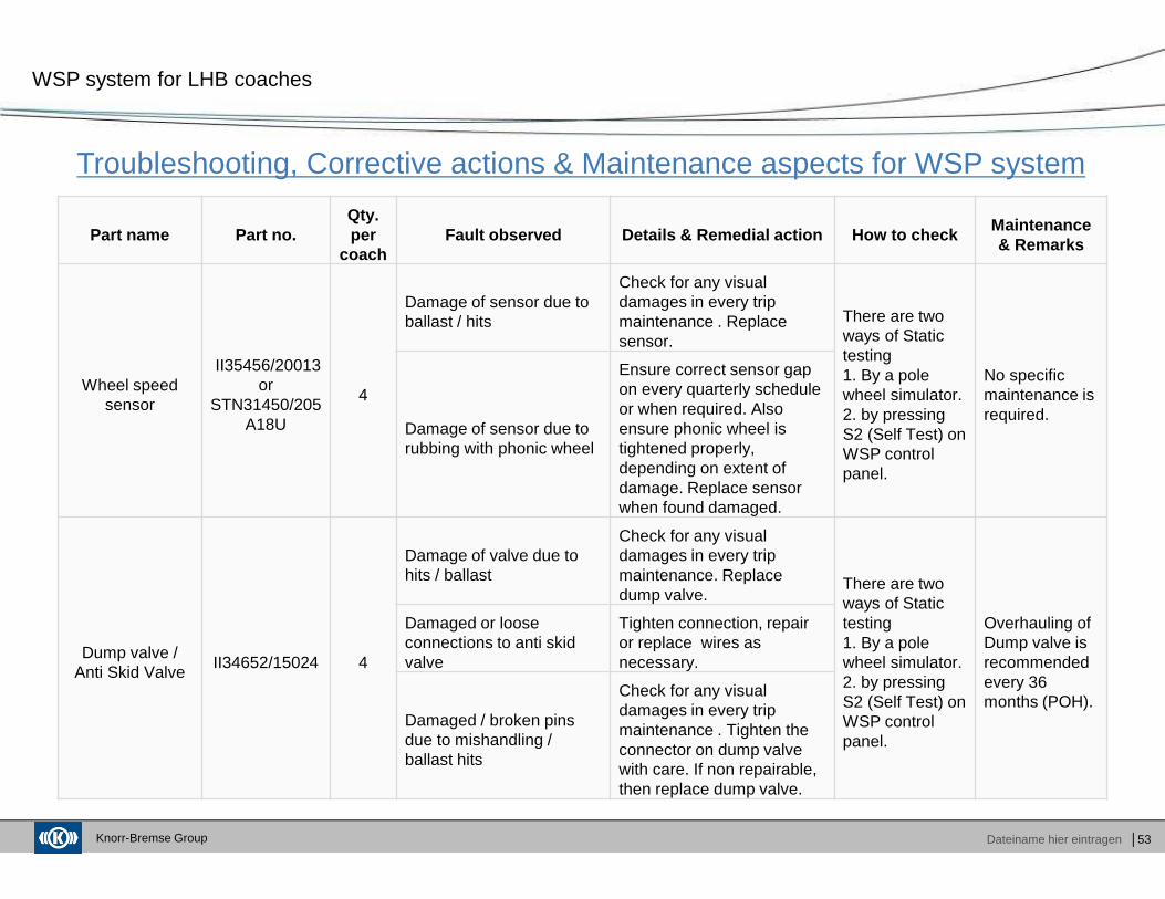
Wheel speed sensor
II35456/20013 or
STN31450/205A18U
4
Damage of sensor due to ballast / hits
Check for any visual damages in every trip maintenance . Replace sensor.
There are two ways of Static testing 1. By a pole wheel simulator. 2. by pressing S2 (Self Test) on WSP control panel.
No specific maintenance is required.
Damage of sensor due to rubbing with phonic wheel
Ensure correct sensor gap on every quarterly schedule or when required. Also ensure phonic wheel is tightened properly, depending on extent of damage. Replace sensor when found damaged.
Dump valve / Anti Skid Valve
II34652/15024 4
Damage of valve due to hits / ballast
Check for any visual damages in every trip maintenance. Replace dump valve.
There are two ways of Static testing 1. By a pole wheel simulator. 2. by pressing S2 (Self Test) on WSP control panel.
Overhauling of Dump valve is recommended every 36 months (POH).
Damaged or loose connections to anti skid valve
Tighten connection, repair or replace wires as necessary.
Damaged / broken pins due to mishandling / ballast hits
Check for any visual damages in every trip maintenance . Tighten the connector on dump valve with care. If non repairable, then replace dump valve.
Knorr-Bremse Group Dateiname hier eintragen │54
Troubleshooting, Corrective actions & Maintenance aspects for WSP system
WSP system for LHB coaches
Part name Part no.Qty. per
coachFault observed Details & Remedial action How to chec k
Maintenance & Remarks
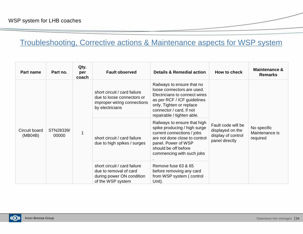
Circuit board (MB04B)
STN28339/00000
1
short circuit / card failure due to loose connectors or improper wiring connections by electricians
Railways to ensure that no loose connectors are used. Electricians to connect wires as per RCF / ICF guidelines only. Tighten or replace connector / card, if not repairable / tighten able.
Fault code will be displayed on the display of control panel directly
No specific Maintenance is requiredshort circuit / card failure
due to high spikes / surges
Railways to ensure that high spike producing / high surge current connections / jobs are not done close to control panel. Power of WSP should be off before commencing with such jobs .
short circuit / card failure due to removal of card during power ON condition of the WSP system
Remove fuse 63 & 65 before removing any card from WSP system ( control Unit).
Knorr-Bremse Group Dateiname hier eintragen │55
Troubleshooting, Corrective actions & Maintenance aspects for WSP system
WSP system for LHB coaches
Part name Part no.Qty. per
coachFault observed Details & Remedial action How to chec k
Maintenance & Remarks
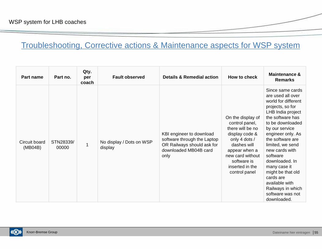
Circuit board (MB04B)
STN28339/00000
1No display / Dots on WSP display
KBI engineer to download software through the Laptop OR Railways should ask for downloaded MB04B card only
On the display of control panel,
there will be no display code &
only 4 dots / dashes will
appear when a new card without
software is inserted in the control panel
Since same cards are used all over world for different projects, so for LHB India project the software has to be downloaded by our service engineer only. As the software are limited, we send new cards with software downloaded. In many case it might be that old cards are available with Railways in which software was not downloaded.
Knorr-Bremse Group Dateiname hier eintragen
Agenda
│56
Company Overview
Functioning of WSP
Maintenance of WSP
Fault diagnosis
Spares stocking at sheds
� Group Product Overview� KB India New Facility
� Main Components� Salient features of WSP� Control Logic� Working principle of WSP
� WSP fault codes� WSP checking procedure� Precaution for failure of WSP Parts
� Troubleshooting
� Recommended list of spares
Knorr-Bremse Group Dateiname hier eintragen │57
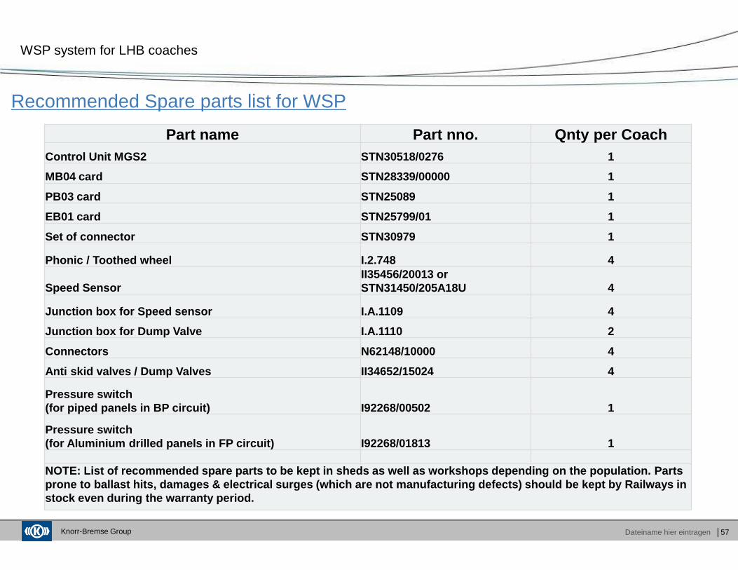
Recommended Spare parts list for WSP
WSP system for LHB coaches
Part name Part nno. Qnty per Coach Control Unit MGS2 STN30518/0276 1
MB04 card STN28339/00000 1
PB03 card STN25089 1
EB01 card STN25799/01 1
Set of connector STN30979 1
Phonic / Toothed wheel I.2.748 4
Speed SensorII35456/20013 or STN31450/205A18U 4
Junction box for Speed sensor I.A.1109 4
Junction box for Dump Valve I.A.1110 2
Connectors N62148/10000 4
Anti skid valves / Dump Valves II34652/15024 4
Pressure switch (for piped panels in BP circuit) I92268/00502 1
Pressure switch (for Aluminium drilled panels in FP circuit) I92268/ 01813 1
NOTE: List of recommended spare parts to be kept in sheds as well as workshops depending on the populat ion. Parts prone to ballast hits, damages & electrical surges (which are not manufacturing defects) should be kep t by Railways in stock even during the warranty period.
Knorr-Bremse Group
Thank you very much for your attention
Knorr-Bremse India Pvt Ltd.
51/4, Delhi Mathura Road,
Village & PO Baghola
Palwal - 121102, Haryana
Phone: +1275 222 402/403/404
Fax: +1275 222755
E-mail: [email protected]
www.knorr-bremse.com