Embed Size (px)
Citation preview

Introduction
This manual has been provided by the manufacturer’s to provide instructions covering the operation and maintenance of the appliances and equipment contained within your recreational vehicle.
Nothing in this manual creates any warranty, either express or implied. The only warranty offered by the manufacturer is set forth in the limited warranty applicable to your vehicle.
The limited warranty provided by the manufacturer and the limited warranties issued by component manufacturers require
periodic service and maintenance, and the owner’s failure to provide this service and/or maintenance may result in the loss of warranty coverage for that item. The owner should review the manufacturer’s limited warranty
and the limited warranty of all other manufacturers.
Included in this manual are instructions for operating some components which may be optional on your vehicle.
This manual is devoted to instructions on travel trailers and fifth wheels. We hope you will have many years of vacationing pleasure.
Some items described in this manual may or may not pertain to your particular unit. Standard items and/or options may vary.
1
Dear Valued Customer,
Thank you for purchasing a Dutchmen Manufacturing, Inc. product! The following manual outlines the THOR Exclusive One Year Bumper to Hitch Limited Warranty, Two Year Structural and Appliance Limited Warranty simply and clearly detailing the most impressive coverage in the industry for towable products.
We are confident that you followed the Product Delivery Inspection procedures with your selling dealer; received an extensive walk through and demonstration of your purchase, and had the warranty statement contained in this manual explained to you. The desired ed result is that you are confident that you have been informed of the warranty provided with the product, the operation, the maintenance required, and details of the responsibilities of the manufacturer, dealer, and retail partnership. At Dutchmen Manufacturing, we want you to be able to enjoy your new travel trailer or fifth wheel to the fullest. In the following pages, you will learn about the warranty, the features, and maintenance responsibilities of the product. We encourage owners to review and pay special attention to the following:
• Warranty Statement - please read full warranty statement
• Weight rating - please review the proper loading, hitching, and pulling instructions
• Care and Maintenance - review sealant maintenance requirements
• Slide Room Operation - review operation instructions, maintenance, adjustments
• LP and Appliances - review function and safety equipment provided
• Tire and Lug Nut - review inflation and lug nut torque specifications
• Modifications /Deviations - review that changes or alterations can void the warranty
• Condensation - review causes and advice on how to reduce and control
Your unit has been inspected by the factory, and received a final inspection at the dealership, and then by yourself during the walk through and demonstrations, but we know that sometimes things can go wrong on the road. Please allow your dealership to assist you in remedying any warrantable issues, and should you need to contact our Goshen, Indiana, service facility, please contact us at: 1-574-537-0700. We wish you many seasons of camping with your Dutchmen Manufacturing, Inc. product. Best Regards,
Dutchmen Manufacturing, Inc. Warranty Department
2
INTRODUCTION..................................................................................................................................................................... 1 USING THIS MANUAL............................................................................................................................................................ 8 Caution and Information Symbols........................................................................................................................................... 8 Separate Component Manuals ............................................................................................................................................... 8 Reporting Safety Defects ........................................................................................................................................................ 8 DUTCHMEN WARRANTY...................................................................................................................................................... 9 INSPECTION ........................................................................................................................................................................ 12 UNIT INFORMATION PACKET ............................................................................................................................................ 12 OWNER REGISTRATION .................................................................................................................................................... 12 OBTAINING WARRANTY SERVICE.................................................................................................................................... 12 GET TO KNOW YOUR UNIT BEFORE HEADING OUT...................................................................................................... 12 IF YOU NEED TO MAKE AN APPOINTMENT..................................................................................................................... 12 Call Ahead............................................................................................................................................................................. 12 Be Prepared .......................................................................................................................................................................... 12 Make a List ............................................................................................................................................................................ 12 While Waiting ........................................................................................................................................................................ 12 About Service Calls............................................................................................................................................................... 12 Can’t Find A Dealer? Have An Emergency?......................................................................................................................... 13 Inspecting Your Repairs........................................................................................................................................................ 13 WEIGHT RATING ................................................................................................................................................................. 13 WEIGHT RATINGS - DEFINITIONS..................................................................................................................................... 13 WEIGHT RATINGS - LABELS.............................................................................................................................................. 13 WEIGHT RATINGS - LOCATIONS....................................................................................................................................... 13 Federal Certification Tag....................................................................................................................................................... 13 RVIA Weight Label................................................................................................................................................................ 13 WEIGHING THE TRAILER ................................................................................................................................................... 13 Travel Trailers ....................................................................................................................................................................... 13 Fifth Wheels .......................................................................................................................................................................... 14 APPROXIMATE HEIGHTS ................................................................................................................................................... 14 TIRES AND WHEELS........................................................................................................................................................... 14 Tire Inspection....................................................................................................................................................................... 14 Tire Changing Basics ............................................................................................................................................................ 15 Wheel Nut Torque ................................................................................................................................................................. 15 Wheel Compatibility .............................................................................................................................................................. 16 HITCHING............................................................................................................................................................................. 16 Hitching a Travel Trailer ........................................................................................................................................................ 16 Safety Chains........................................................................................................................................................................ 17 Hitching a Fifth Wheel Trailer................................................................................................................................................ 17 BREAKAWAY SWITCH ........................................................................................................................................................ 17 7-PIN PLUG .......................................................................................................................................................................... 18
3

BRAKES, ELECTRIC............................................................................................................................................................ 18 Adjusting the Brakes ............................................................................................................................................................. 19 Braking Tips .......................................................................................................................................................................... 19 LOADING .............................................................................................................................................................................. 19 LIGHTS ................................................................................................................................................................................. 19 MIRRORS ............................................................................................................................................................................. 19 TOWING................................................................................................................................................................................ 20 Backing Up............................................................................................................................................................................ 20 Passing.................................................................................................................................................................................. 21 Sharply Winding and Narrow Roads..................................................................................................................................... 21 Steep or Long Grades........................................................................................................................................................... 21 Slippery Pavement ................................................................................................................................................................ 21 Freeways and Highways ....................................................................................................................................................... 21 Turning Corners .................................................................................................................................................................... 21 Mud and Sand....................................................................................................................................................................... 21 Parking .................................................................................................................................................................................. 21 Level Towing ......................................................................................................................................................................... 21 SET UP ................................................................................................................................................................................. 21 Leveling and Stabilization ..................................................................................................................................................... 21 Travel Trailer Leveling Procedures ................................................................................................................................... 21 Fifth Wheel Leveling Procedures ...................................................................................................................................... 22 Jacks and Stabilizers ............................................................................................................................................................ 22 Slide Out Systems................................................................................................................................................................. 22 General Tips Concerning Slide Rooms................................................................................................................................. 22 ELECTRIC SLIDE-OUT SYSTEM ........................................................................................................................................ 23 Electrical maintenance ....................................................................................................................................................... 23 Manual Override System....................................................................................................................................................... 23 HAND CRANK SLIDE OUT SYSTEM .................................................................................................................................. 23 MANUAL SLIDE-OUT SYSTEM ........................................................................................................................................... 23 SLIDE ROOM SET UP AND ADJUSTMENTS ..................................................................................................................... 23 BUNK TENT ROOMS ........................................................................................................................................................... 23 Set Up ................................................................................................................................................................................... 23 REAR DOOR/LOADING RAMP OPERATION (SRV Models).............................................................................................. 23 ELECTRICAL SYSTEM ........................................................................................................................................................ 24 12 VOLT SYSTEM-DC.......................................................................................................................................................... 24 120 VOLT SYSTEM (ALSO REFERRED TO AS 110VA/C)................................................................................................. 24 GFCI – (Ground Fault) Circuit Interrupter......................................................................................................................... 24 POWER CORD / SHORE CORD.......................................................................................................................................... 24 30 AMP SERVICE................................................................................................................................................................. 25 50 AMP SERVICE (OPTIONAL)........................................................................................................................................... 25 AVAILABLE POWER ............................................................................................................................................................ 25
4
CONVERTER........................................................................................................................................................................ 25 LP GAS SYSTEM ................................................................................................................................................................. 25 GENERAL INFORMATION................................................................................................................................................... 25 LP REGULATOR .................................................................................................................................................................. 26 Care & Maintenance ............................................................................................................................................................. 26 LP BOTTLES......................................................................................................................................................................... 26 Filling LP Bottles ................................................................................................................................................................... 26 SPLIT-BOTTLE SYSTEMS – (Primarily on Fifth Wheels) .................................................................................................... 27 LP Gas Lines........................................................................................................................................................................ 27 Bleeding Air from LP Gas Lines............................................................................................................................................ 27 LP GAS LEAK DETECTOR .................................................................................................................................................. 27 When to Test Detector .......................................................................................................................................................... 27 When the Alarm Sounds….................................................................................................................................................... 27 PLUMBING SYSTEM............................................................................................................................................................ 27 GENERAL INFORMATION................................................................................................................................................... 27 MONITOR PANEL ................................................................................................................................................................ 27 Operation............................................................................................................................................................................... 28 Erroneous Readings ............................................................................................................................................................. 28 FRESH WATER TANK ......................................................................................................................................................... 28 Fresh Water Fill ..................................................................................................................................................................... 28 City Water Fill ........................................................................................................................................................................ 28 Sanitizing the Fresh Water System....................................................................................................................................... 28 Vibration While Traveling ...................................................................................................................................................... 28 Water Pump .......................................................................................................................................................................... 28 Water Heater ......................................................................................................................................................................... 29 Care & Maintenance ............................................................................................................................................................. 29 Pressure Relief Valve-Weeping or Dripping ......................................................................................................................... 29 Replenishing the Air Pocket .................................................................................................................................................. 29 Water Supply and Odor......................................................................................................................................................... 29 Draining & Storage................................................................................................................................................................ 30 To Drain the Water Heater .................................................................................................................................................... 30 By-Pass Kit............................................................................................................................................................................ 30 Winterization.......................................................................................................................................................................... 30 Method 1 (With By-Pass Kit installed)................................................................................................................................... 30 Method 2 (With By-Pass Kit installed)................................................................................................................................... 30 Removing Antifreeze............................................................................................................................................................. 31 WASTE WATER SYSTEM.................................................................................................................................................... 31 Toilet...................................................................................................................................................................................... 31 Holding Tanks ....................................................................................................................................................................... 31 Dumping Instructions ............................................................................................................................................................ 32 No Fuss Flush (Optional) ...................................................................................................................................................... 32
5

Solid Build Up........................................................................................................................................................................ 32 GAS FURNACE .................................................................................................................................................................... 32 APPLIANCES........................................................................................................................................................................ 32 Air Conditioner....................................................................................................................................................................... 32 Kitchen Range and Oven...................................................................................................................................................... 33 Range Exhaust hood............................................................................................................................................................. 33 Microwave ............................................................................................................................................................................. 33 Refrigerator (self contained models)..................................................................................................................................... 33 TV Antenna (optional) ........................................................................................................................................................... 33 AM/FM Radio with Cassette or CD Players .......................................................................................................................... 33 PROLONGED OCCUPANCY ............................................................................................................................................... 33 VENTILATION AND MOISTURE CONTROL ....................................................................................................................... 33 Dripping Ceiling Vents........................................................................................................................................................... 34 MOLDS.................................................................................................................................................................................. 34 CARE AND MAINTENANCE ................................................................................................................................................ 34 EXTERIOR............................................................................................................................................................................ 34 SEALS & ADHESIVES.......................................................................................................................................................... 34 WINDOWS (EXTERIOR) ...................................................................................................................................................... 35 FIBERGLASS / GEL COAT FINISH...................................................................................................................................... 35 METAL .................................................................................................................................................................................. 35 ABS PLASTIC / MOLDED PARTS ....................................................................................................................................... 35 ROOF.................................................................................................................................................................................... 35 FRAME & CHASSIS ............................................................................................................................................................. 36 Frame & Bumper................................................................................................................................................................... 36 Steps ..................................................................................................................................................................................... 36 Hitch Couplers....................................................................................................................................................................... 36 Fifth Wheel Coupler .............................................................................................................................................................. 36 Safety Chains........................................................................................................................................................................ 36 Jacks ..................................................................................................................................................................................... 36 TIRES & WHEELS ................................................................................................................................................................ 36 Wheel Bearing Lubrication .................................................................................................................................................... 36 Brake Adjustment.................................................................................................................................................................. 37 BATTERY.............................................................................................................................................................................. 37 Inspection.............................................................................................................................................................................. 37 Battery Storage ..................................................................................................................................................................... 37 APPLIANCES ....................................................................................................................................................................... 37 MISCELLANEOUS................................................................................................................................................................ 37 Bed Spreads.......................................................................................................................................................................... 37 Blinds and Shades ................................................................................................................................................................ 37 Cabinet Doors and Drawers (Solid Hardwoods) ................................................................................................................... 38 Carpeting............................................................................................................................................................................... 38
6

Ceilings and Walls................................................................................................................................................................. 38 Countertops........................................................................................................................................................................... 38 Draperies............................................................................................................................................................................... 38 Faucets and Fixtures............................................................................................................................................................. 38 Flooring, Vinyl........................................................................................................................................................................ 38 Glass & Mirrors...................................................................................................................................................................... 38 Fabric & Upholstery............................................................................................................................................................... 38 Sinks, Tubs, and Toilets........................................................................................................................................................ 38 GENERAL MAINTENANCE SCHEDULE ............................................................................................................................. 39 MAINTENANCE & SERVICE RECORDS............................................................................................................................. 42
7

USING THIS MANUAL
Dutchmen Manufacturing, Inc has provided this manual solely for the purpose of providing instructions about the operation and maintenance of its recreational vehicle. Nothing in this manual creates any warranty, either express or implied. The only warranty offered by Dutchmen Manufacturing, Inc is set forth in the Limited Warranty applicable to your vehicle.
Reporting Safety Defects If you believe that your vehicle has a defect which could cause a crash or could cause injury or death, you should immediately inform the National Highway Traffic Safety Administration (NHTSA) in addition to notifying the manufacturer.
If NHTSA receives similar complaints, it may open an investigation, and if it finds that a safety defect exists in a group of vehicles, it may order a recall and remedy campaign. However, NHTSA cannot become involved in individual problems between you, your dealer or the manufacturer.
Caution and Information Symbols Through out this manual we have placed special emphasis on items that require special attention. Denotes information that the user should be highly aware of, as failure to heed these cautions or warnings may result in product damage, property damage, serious injury or fatality. To contact NHTSA, you may either call the Auto Safety Hotline toll-
free at 1-800-424-9393 (or 366-0123 in the Washington, DC area) or write to: NHTSA, U.S. Department of Transportation, Washington, DC 20590. You can also obtain other information about motor vehicle safety from the Hotline.
SPECIAL ATTENTION SHOULD BE GIVEN TO ALL INFORMATION PRECEDED BY THIS SYMBOL. FAILURE TO DO SO MAY RESULT IN PRODUCT DAMAGE, PROPERTY DAMAGE, SERIOUS INJURY, OR FATALITY.
Instructions included in this manual are for operating some components, which may be optional on your vehicle. This manual is devoted to instructions on travel trailers and fifth wheels.
We hope you will have many years of vacationing pleasure. This manual is based on the latest information available at the time of publication. Due to continuous product development and improvements, Dutchmen Manufacturing, Inc reserves the right to make changes in product specifications and components without prior notice.
READ THE ENTIRE MANUAL AND HEED ALL CAUTION AND WARNING STATEMENTS, PRIOR TO OPERATION OF THE RECREATIONAL VEHICLE.
The limited warranty and the limited warranties issued by component manufacturers require periodic service and maintenance, and the owner’s failure to provide this service and/or maintenance may result in loss of warranty coverage for that item. The owner should review Dutchmen Manufacturing, Inc.’s limited warranty and the limited warranty of all other manufacturers.
Separate Component Manuals Missing a component manual? Separate component manuals for the various items we use are available as downloadable files at our web site. The web site address is www.dutchmenmfg.com.
8

DUTCHMEN WARRANTY
One YTwo Year S
For: Travel Trailers and Fifth Wheels Manufa
COVERAGE PROVIDED: GENERAL
Your new travel trailer, including the plumbing, heating andsystems, installed by the manufacturer, is warranted unduse to be free from manufacturing defects in matworkmanship for a period of one (1) year from date of puthe original owner.
This warranty extends to the first retail purchaser, is not trand begins on the date of original retail delivery or the datetrailer is first placed into service (whichever occurs fiwarranty extends for a period of one (1) year (Bumper to Htwo (2) years (structural and appliance) from such datenotice of defects must be given to the selling dealemanufacturer no later than ten (10) days after the expiratiapplicable warranty. Warranty repairs, if required, will without charge and within industry standards, after your trais taken to an authorized service center.
NOTE: UNITS ARE MANUFACTURED RECREATIONAL PURPOSES, UNITS USECOMMERICAL, RESIDENTIAL, OR RENTAL MAYOUR WARRANTY.
COVERAGE PROVIDED: STRUCTURAL
Your new travel trailer’s structure is warranted to be fmanufacturing defects in material and workmanship for a two (2) years from date of purchase to the original owstructure consists of the walls, floor and roof, and the attaceach other, but does not include attachments to the structurbut not limited to, frame, axles, windows, doors, cabinets, vrubber/vinyl roof.
COVERAGE PROVIDED: APPLIANCES
The major appliance warranty is administered by DManufacturing for two (2) years from date of purchase. Thappliances installed in your travel trailer by the factory have vendor warranty statements offering a two year coveraoriginal consumer purchaser and is not transferable. DManufacturing and its dealer network will process theresulting from an appliance manufacturing defect through warranty policies and procedures. This coverage includes oven, refrigerator, water pump, furnace, water heater, TV, sconverter, depending on options installed.
Two Year Limited Warranty ear Bumper to Hitch Limited Warranty tructural and Appliance Limited Warranty
ctured By Dutchmen Manufacturing Sold in the United States and Canada
OWNER’S OBLIGATIONS:
The owner is responsible for normal maintenance; however, minor adjustments (such as adjustments to the interior or exterior doors, LP regulator pressure, cabinet latches, TV antenna control, voids in sealants, etc.) will be performed by the dealer during the first ninety (90) days of warranty coverage. Thereafter, such adjustments are the responsibility ofthe owner as normal maintenance, unless required as a direct result of repair or replacement of a defective part under this warranty.
electrical er normal erial and rchase to
ansferable the travel rst). This itch) and . Written r or the on of the be made vel trailer
If a problem occurs which the owner believes is covered by this warranty, the owner shall contact the selling dealer, or other authorized dealer, giving them sufficient information to resolve the matter.
The owner is also responsible for inspecting and maintaining sealants or seals around all attachments and seams related to the structure.
FOR D AS Y VOID
WARNING: The owner’s failure to perform such inspection and maintenance, which results in water damage or any other damage, shall void the warranty.
The owner shall be responsible to deliver the travel trailer to the dealer, authorized service center, or factory for all warranty repairs. It is the owner’s responsibility to return the vehicle to an authorized service center for any repairs that may be required.
ree from period of ner. The hment to e such as, ents, and It is the owner’s responsibility to notify the selling dealer of a defect
in a timely manner. Failure to notify in a timely manner will void all or portions of this one year/two year limited warranty.
CONSEQUENTIAL AND INCIDENTAL DAMAGES: utchmen e vendor their own ge to the utchmen
warranty its normal the range, tereo, and
Dutchmen Manufacturing shall not be liable for any incidental or consequential damages such as, expenses for transportation, lodging, loss or damage to personal property, loss of use of owner’s product, inconvenience or loss of income. Some states do not allow the exclusion or limitation of incidental or consequential damages, so the above limitation or exclusion may not apply to you.
9
This warranty gives you specific legal rights and you may also have other rights, which vary from state to state. Dealers or any other persons are not authorized to make modifications to this warranty. Any additional statements concerning this warranty, whether oral or written, are not the responsibility of the manufacturer and should not be relied upon.
DELIVERY
To assist in avoiding problems with your coach, we recommend you do the following:
1. Read the warranty. Go over it thoroughly with your dealer. 2. Inspect the vehicle. Do not accept delivery until you have gone through the coach with the dealer. The manufacturer has provided a checklist to be used during retail delivery. Check each item on the list and make sure the dealer does the same. Do not sign this checklist until you are satisfied with each inspection. 3. Ask questions about anything concerning your coach you do not understand. 4. Be sure your tow vehicle has the capacity to pull the coach you have selected.
Throughout the manufacturing process, your travel trailer has been inspected by our quality inspectors. However, our final inspection at the factory is not the last one. The pre-delivery inspections (including systems check) your dealer performs are the final inspections due to the unit prior to receiving your new coach. Your dealer should assist you in understanding the limited warranties and completing necessary forms to activate them.
DEALER’S OBLIGATIONS:
By agreement with the manufacturer, the dealer is obligated to maintain the travel trailer prior to retail sale, to perform a detailed pre-delivery inspection and to make any repairs necessary to correct defects in material or workmanship. 1. Maintain the travel trailer prior to retail sale. 2. Perform a detailed pre-delivery inspection (including all systems check) and make any repairs necessary to correct defects in material or workmanship. 3. Provide a customer walk through. This is done to familiarize the customer with the coach, its systems, components and its operation. The manufacturer has provided a checklist to be used during retail delivery. Do not sign this checklist
WHAT IS NOT COVERED BY THIS WARRANTY :
1. Tires and batteries, and other equipment, which are covered by the separate warranties of the respective manufacturers of these components. 2. Damage caused by or related to:
A: Accidents, misuse or negligence. B. Alteration or modification of the travel trailer or damage incurred resulting from alteration or modification. C. Environmental conditions (salt, hail, chemicals in
atmosphere, etc.). D. Failure to comply with instructions contained in the Owners Manual
3. Normal deterioration due to wear or exposure, such as fading of fabrics or drapes, carpet wear, etc.
4. Normal maintenance and service items such as light bulbs, fuses, lubricants, sealant and seals, slide adjustments, door adjustments, awning tension, etc. or damages resulting from lack of maintenance.
5. Extra expenses such as transportation to and from dealer or authorized service center, loss of time, loss of pay, loss of use of the travel trailer, inconvenience, commercial loss, towing charges, bus fare, vehicle rental, incidental charges such as telephone calls or lodging bills, or other incidental or consequential damages (other than injury to the person).
6. Any unit used as a commercial unit, residential unit or used as a rental unit.
7. Additional charges for transportation to and from on-site service.
8. Condensation on any window or other parts as a result of condensation including any mold or related water damage.
LIMITATION OF IMPLIED WARRANTIES:
Implied warranties, including any warranty of merchantability or fitness for a particular purpose, are limited in duration to the terms of this written warranty. Some states do not allow limitation on how long an implied warranty lasts, so the above limitation may not apply to you.
Dutchmen Manufacturing Inc. Parts, Service, & Warranty
2164 Caragana Court Goshen, IN 46526
Phone: (574) 537-0700 Fax: (574)-537-0496 [email protected]
10

Separate component mafil
w
Manufacturer’s Warranty Contacts
A&E / DOMETIC / DUO-THERM US
Service Office 509 S. Poplar Street Lagrange, IN 46761 800-544-4881 Canada Service Office 866 Langs Drive Cambridge, Ontario N3H 2N7 519-653-7390 ALKO-KOBER Elkhart, IN 46516 574-264-6651 PARALLAX – USA BR WHOLESALE 800-848-0934 MASTERTECH 800-848-0558 PARALLAX – CAN J&J sales 604-534-6336 VERN GIBSON 818-897-7577 SUBURBAN MFG. Customer Service Center 676 Broadway Street Dayton, TN 37321 423-775-2131 ONAN CORPORATION 1400 73RD Ave., NE Minneapolis, MN 55432 800-888-ONAN SHURFLO 12650 Westminster Ave. Santa Ana, CA 92706-2100
Missing a component manual?
nuals for the various items we use are available as downloadable es at our web site. The website address is :
ww.dutchmenmfg.com.
A BAL RV PRODUCTS GROUP 365 W. Victoria St. Compton, CA 90220 310-639-4000 ANTENNA TEK, INC 425 S. Bowen, #4 Longmount, CO 80501 303-772-9591 WINEGARD – USA Winegard USA 3000 Kirkwood St. Burlington, IA 52601-2000 303-754-0600 WINEGARD – CAN Coast Distribution – Canada Alberta 403-720-0046 Quebec 514-866-3613 ATWOOD MOBILE PRODUCTS 4750 Hiawatha Drive Rockford, IL 61103 800-825-4328 THETFORD – USA P.O. Box 1285 Ann Arbor, MI 48106 800-521-3032 THETFORD – CAN 2710 Slough St. Mississauga, ONT L4T1G3 905-671-0255
11
INSPECTION GET TO KNOW YOUR UNIT BEFORE HEADING OUT.
To assist you in avoiding problems, Dutchmen Manufacturing, Inc requests that each dealer review the limited warranty and inspect the unit along with you. The dealer has been provided with a pre-delivery checklist. Review this checklist with the dealer. Do not sign the checklist until this review is complete and any questions about anything you do not understand have been answered.
Throughout the manufacturing process, your recreational vehicle has been inspected by qualified inspectors and then again at the dealership. As the owners, however, you will be the first to camp and extensively use every system. Dutchmen Manufacturing, Inc wants the first camping experience to be a happy one and recommends a “Trial Camping Experience” before heading out. Plan a weekend in the yard or driveway and really camp in your unit.
By camping for several days, full time in your unit, you will have the opportunity to use and become accustomed to the systems within your unit and find out what items are needed or not needed while camping. Note any questions that arise, difficulties encountered or problems that occur. After your trial, call your dealer and ask any questions that have arisen. Getting to know your unit before the first adventure can save a lot of frustration and leave more time for fun!
UNIT INFORMATION PACKET
In addition to this Owner’s Manual, a unit information packet is located within your new recreational vehicle. Inside the packet are product manuals and information on systems and equipment in the coach. Individual product warranty registrations accompany this information and should be completed and mailed promptly. Some components in this manual or packet may be components of a differing product line and/or are optional equipment. Inclusion of these items does not suggest that they are or may be available for a specific recreational vehicle. IF YOU NEED TO MAKE AN APPOINTMENT
Call Ahead Give thought to an appointment time and call ahead. Mondays and Fridays are generally the busiest times at a dealer’s service center, as are right before seasonal holidays.
OWNER REGISTRATION
As a convenience to you, the owner registration form is completed at the dealership at the time of delivery. After an owner signs this form, the dealer will send the completed form to Dutchmen Manufacturing, Inc within 30 days. Please make sure this form is completed and signed prior to leaving the dealership.
Be Prepared If warranty work is to be done, please have a copy of your warranty paperwork available and provide the service center with any helpful information on past repairs that may pertain and help the technicians in diagnosing the problem.
OBTAINING WARRANTY SERVICE Make a List
Dutchmen Manufacturing, Inc recommends obtaining service from your dealer or the nearest authorized repair facility. Service must be obtained within a reasonable time after discovery of the defect and prior to the applicable warranty expiration period. If assistance is needed in locating an authorized repair center, please contact Dutchmen Service at 1-574-537-0700
Have a list ready and be reasonable with repair expectations. Some repairs may require special order parts or parts shipped from a manufacturer. Explain what you would like to have done over the phone or stop by ahead of time so that you and the service manager can discuss possible repair times.
While Waiting Please have the following available when you call. Drop your unit off if possible. If you can wait on your repair, do not
be surprised if you cannot enter the repair area. Many insurance policies prohibit customers or non-personnel from entering into the work area for safety reason.
• Vehicle Identification Number (17 digit Serial #)
• Model # About Service Calls
• Date of Purchase Please note: Dutchmen Manufacturing’s, Inc Limited Warranty covers warrantable repairs that are performed by an authorized Dutchmen dealer at their service center or facility only. It is important for the owner to know that if you are unable to bring your unit in for repairs, Dutchmen Manufacturing, Inc is not responsible for any costs incurred for the service call charge, or time accrued to come out to your unit. Your unit is a recreational vehicle and not intended, nor manufactured as a permanent residence.
• Description of the problem
• Previous repair history & location (if applicable).
In order to assist you, a “Personal Records Page” is located in the appendix.
12

The maximum permissible weight of this trailer when fully loaded. It includes all weight at the trailer’s axle(s), plus the tongue or pin.
Can’t Find A Dealer? Have An Emergency? Call Dutchmen Customer Service. We can help locate a dealer nearby or, in emergencies or special circumstances, provide authorization to a local repair facility. UVW (Unloaded Vehicle Weight)
The weight of this trailer as manufactured at the factory. It includes all weight at the trailer axles(s) and the tongue or pin. If applicable, it also includes full generator fluids, including fuel, engine oil, and coolants.
Before using any non-authorized dealer for any warranty repair, call Dutchmen first!
Inspecting Your Repairs CCC (Cargo Carrying Capacity) Dutchmen Manufacturing, Inc and your dealer want you to be
satisfied with any repair. After a repair is performed, inspect it thoroughly. Check off your list and go over the repairs with the service center representative. Once satisfied, sign the Dutchmen Manufacturing, Inc Company Warranty Claim. In the event a problem should reoccur after you have left the dealership, contact the repair center or Dutchmen Manufacturing, Inc as soon as possible, so that the situation can be resolved expediently.
Is equal to GVWR minus each of the following: UVW, full fresh (potable) water weight (including water heater), and full LP-Gas weight.
GAWR (Gross Axle Weight Rating) The maximum allowable weight that an axle system is designed to carry.
WEIGHT RATINGS - LABELS WEIGHT RATING The information on the weight ratings is contained on two labels: The Federal Certification Tag and the RVIA Weight Label. Each label contains the Vehicle Identification Number (VIN) / Serial Number for the vehicle rated. These ratings are specific for each travel trailer and fifth wheel manufactured. Use only the ratings found on these labels.
YOU MUST NOT EXCEED THE GVWR OR GAWR OF THE TRAILER (SEE DEFINITIONS). TO VERIFY GVWR, TOTAL THE LOADED HITCH AND AXLE WEIGHTS. IF THIS TOTAL EXCEEDS GVWR, YOU MUST REMOVE CARGO UNTIL THE VEHICLE WEIGHT IS WITHIN THIS LIMIT. YOU CAN VERIFY THAT THE RV AXLES ARE NOT OVERLOADED BY COMPARING THE LOADED AXLE WEIGHT WITH THE GWAR. IF THE READING IS ABOVE THIS LIMIT, REDISTRIBUTE CARGO LOAD.
WEIGHT RATINGS - LOCATIONS Federal Certification Tag The Federal Certification Tag on travel trailers and fifth wheels can be located on the Road Side (Off Door Side) near the front of the unit. This tag contains the GVWR, GAWR (front & rear) and tire pressure limits.
Weight distribution is an important factor when loading a travel trailer or fifth wheel. A recreational vehicle with the cargo distributed properly will result in efficient, trouble-free towing. Loading the RV, as evenly as possible, and then weighing the loaded RV can accomplish proper weight distribution. Keep heavier items as low as possible and accomplish proper weight distribution. Keep heavier items as low as possible and distribute evenly, front to back and side to side. Securing your cargo can prevent damages from shifting cargo during towing and maintain the weight distribution balance achieved.
RVIA Weight Label The RVIA Weight Label is located on the inside of an upper kitchen cabinet door. In general, the tag is affixed to the cabinet above or adjacent to the sink. This tag provides the GVWR rating, the UVW (Unloaded Vehicle Weight) and the computation for CCC (Cargo Carrying Capacity).
WEIGHING THE TRAILER You must not exceed the GVWR or GAWR of the trailer (see
definitions). To verify GVWR, total the loaded hitch and axle weights. If this total exceeds GVWR, you must remove cargo until the vehicle weight is within this limit. You can verify that the RV axles are not overloaded by comparing the loaded axle weight with the GWAR. If the reading is above this limit, redistribute cargo load.
Travel Trailers Drive the loaded trailer onto the scales as shown in the picture below, making sure that the hitch will be the only contact point with the scales after unhooking. Unhook and drive the tow vehicle off the scales. Level the trailer and record hitch weight.
Finally, make sure the tongue or pin weight of the loaded travel trailer/fifth wheel falls within the limits of the tow vehicle. Hookup to the trailer and drive forward on the scales until only the
trailer axles are on the scale. Level the trailer and record axle weight.
WEIGHT RATINGS - DEFINITIONS To determine overall weight, add the hitch weight plus axles. GVWR (Gross Vehicle Weight Rating)
13
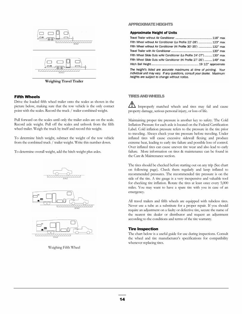
APPROXIMATE HEIGHTS
Weighing Travel Trailer
TIRES AND WHEELS Fifth Wheels
Drive the loaded fifth wheel trailer onto the scales as shown in the picture below, making sure that the tow vehicle is the only contact point with the scales. Record the truck / trailer combined weight.
Improperly matched wheels and tires may fail and cause property damage, serious personal injury, or loss of life.
Pull forward on the scales until only the trailer axles are on the scale. Record axle weight. Pull off the scales and unhook from the fifth wheel trailer. Weigh the truck by itself and record this weight.
Maintaining proper tire pressure is another key to safety. The Cold Inflation Pressure for each axle is located on the Federal Certification Label. Cold inflation pressure refers to the pressure in the tire prior to traveling. Always check your tire pressure before traveling. Under inflated tires will cause excessive sidewall flexing and produce extreme heat, leading to early tire failure and possible loss of control. Over inflated tires can cause uneven tire wear and also lead to early failure. More information on tires & maintenance can be found in the Care & Maintenance section.
To determine hitch weight, subtract the weight of the tow vehicle from the combined truck / trailer weight. Write this number down.
To determine overall weight, add the hitch weight plus axles.
The tires should be checked before starting out on any trip (See chart on following page). Check them regularly and keep inflated to recommended pressures. The recommended tire pressure is on the side of the tire. A tire gauge is a very inexpensive and valuable tool for checking tire inflation. Rotate the tires at least once every 5,000 miles. You may want to have a spare tire with you in case of an emergency.
All travel trailers and fifth wheels are equipped with tubeless tires. Never use a tube as a substitute for a proper repair. If you should require an adjustment on a faulty or defective tire, secure the name of the nearest tire dealer or distributor and request an adjustment according to the conditions and terms of the tire warranty.
Tire Inspection The chart below is a useful guide for use during inspections. Consult the wheel and tire manufacturer’s specifications for compatibility whenever replacing tires.
Weighing Fifth Wheel
14

TU
Bc
P(
W
Pt
ire Changing Basics se emergency flares when near a road or highway.
lock the wheels on the opposite side from the tire you wish to hange to prevent accidental movement.
osition a hydraulic jack on the frame close to the spring hanger. Never attempt to use a stabilizer jack to lift the unit)
NEVER USE A STABILIZER JACK TO RAISE THE UNIT. ONLY USE AN APPROPRIATELY RATED HYDRAULIC JACK.
1. Loosen the Lug Nuts
2. Raise the trailer until the tire clears the ground.
3. Remove the Lug Nuts and remove the tire.
4. Install the spare tire and install the lug nuts until the wheel is tight against the hub.
5. Lower the trailer.
6. Torque the lug nuts following the Wheel Nut Torque Procedure in this manual.
7. Recheck the torque every 50 miles for the first 200 miles.
heel Nut Torque
ALWAYS TORQUE WHEEL NUTS TO THE WHEEL MANUFACTURER’S SPECIFICATIONS! OVER OR UNDER-TORQUED LUG NUTS CAN CAUSE THE WHEEL TO SEPARATE FROM THE WHEEL MOUNTING SURFACE DURING OPERATION, CAUSING PROPERTY DAMAGE, PERSONAL INJURY, OR LOSS OF LIFE.
roper wheel nut torque is very important to safe and dependable railering. The wheel and axle systems used in travel trailers and fifth
wheels are similar, yet different, in many ways to those used on cars and trucks. These differences are important and require special attention to wheel nut torque both while the trailer is new and throughout the trailer’s life.
Trailer wheels must carry much higher loads per wheel than passenger car or truck wheels. Each wheel may carry 1000 pounds and higher. Furthermore, wheels on tandem axle trailers do not steer, and are subjected to very high side load stress whenever the trailer makes a tight turn. When you go around corners, especially slow, tight ones, the wheels on your trailer are subjected to these strong side loads. This tends to flex the wheel and gradually loosen the wheel nuts. Although the materials and manufacturing methods are maximized for this kind of service, these extra loads can cause stress, which can result in flexing and loosening of wheel nuts.
Before each trip and any time a wheel is replaced, be sure to tighten the wheel nuts, following the sequence shown in the relevant lug pattern below. Set the torque specification in three stages as seen in the chart below. If the wheel was replaced, check the torque every 50 miles of the first 200 miles of travel.
1s2nd3rd
IT IS PROPERDURINGOPERATBEEN LEAVINSETTLINCOMPOMILES LOOSEN
If you notice wheel wheel, especially at This problem is usudamaged lug bolt th
15
Torque Stages t Stage 20 to 25 ft/lbs Stage 55 to 60 ft/lbs Stage 85 to 95 ft/lbs
CRITICAL THAT THE WHEELS BE LY TORQUED EVERY 50 MILES THE FIRST 200 MILES OF ROAD ION. ALTHOUGH THE WHEELS HAVE PROPERLY TORQUED BEFORE
G THE MANUFACTURING PLANT, G AND WEARING IN OF
NENTS DURING THE FIRST FEW OF OPERATION MAY CAUSE SOME ING OF THE WHEEL NUTS.
wobbling or hear a rattling sound coming from a low speeds, a wheel lug nut may have come lose. ally caused by improper tightening or by faulty or reads. If you have a reason to believe a lug nut
has come loose, safely stop the vehicle at the side of the road as soon as possible. Put up warning devices. Remove the lug caps and check the tightness of all the lug nuts. Tighten all lug nuts to the specified torque, using a torque wrench. If log bolt threads are damaged or faulty, get professional service help.
HITCHING
AN IMPROPERLY COUPLED TRAILER CAN RESULT IN DEATH OR SERIOUS INJURY.
USE OF A TOW VEHICLE WITH A TOWING CAPACITY LESS THAN THE LOAD RATING OF THE TRAILER CAN RESULT IN LOSS OF CONTROL, AND MAY LEAD TO DEATH OR SERIOUS INJURY.
DO NOT TOW THE TRAILER WITH MISSING LUG NUTS OR FAULTY LUG BOLTS.
Wheel Compatibility
IMPROPERLY MATCHED WHEELS AND TIRES MAY FAIL AND CAUSE PROPERTY DAMAGE, SERIOUS PERSONAL INJURY, OR LOSS OF LIFE
Be sure your hitch and tow vehicle are rated for the Gross Vehicle Weight Rating (GVWR) of your trailer. Be sure the hitch load rating is equal to or greater than the load rating of the coupler. Be sure the hitch size matches the coupler size. Observe the hitch for wear, corrosion and cracks before coupling. Replace worn, corroded or cracked hitch components before coupling the trailer to the tow vehicle. Be sure the hitch components are tight before coupling the trailer to the tow vehicle.
Dutchmen Manufacturing, Inc installs axle systems with hubs and drums that are compatible with many wheels used in the recreational vehicle industry that have matching bolt patterns. If the original manufacturer installed equipment is in need of replacement, the wheel manufacturer should be contacted for proof of compatibility prior to replacement and use.
Hooking up your trailer will become quite simple to you after a little practice and following these step-by-step instructions.
Hitching a Travel Trailer Customers replacing original equipment that has not been tested for compatibility must ensure the replacements are compatible to the hub and drum assembly installed. Such elements of compatibility include, but are not limited to:
THE PROPER SELECTION AND CONDITION OF THE COUPLER AND HITCH IS ESSENTIAL TO THE SAFE TOWING OF YOUR TRAILER. A LOSS OF COUPLING MAY RESULT IN DEATH OR SERIOUS INJURY. • Diameter of the hub-mounting surface.
• BE SURE THE HITCH LOAD RATING IS EQUAL TO OR GREATER THAN THE LOAD RATING OF THE COUPLER.
• Stud length and diameter.
• Location and number of studs. • BE SURE THE HITCH SIZE MATCHES THE COUPLER SIZE.
• Center hole diameter for the wheel. • OBSERVE THE HITCH FOR WEAR, CORROSION AND
CRACKS BEFORE COUPLING. REPLACE WORN, CORRODED OR CRACKED HITCH COMPONENTS BEFORE COUPLING THE TRAILER TO THE TOW VEHICLE.
• Wheel mounting offset from the rim center.
• Rated capacity of the wheel.
• Wheel fastener torque. • BE SURE THE HITCH COMPONENTS ARE TIGHT
BEFORE COUPLING THE TRAILER TO THE TOW VEHICLE. • Wheel nut size and shape.
1. Crank the tongue of the trailer jack up until the hitch coupler is high enough to clear the tow vehicle.
Impact of any added wheel accessories (such as decorative center caps) that could affect proper seating of the wheel to the hub surface.
2. Back the tow vehicle to the trailer until the hitch ball is directly under the coupler on the trailer.
Certain tests are recommended by the manufacturer(s) of factory installed equipment, such as the cornering fatigue test based on SAE J1095/SAE J267 and field tests, are recommended for all wheels and rims to be installed in place of original factory equipment. Contact the wheel manufacturer to verify compatibility with the factory installed equipment prior to replacement.
3. Set the parking brakes, raise the locking latch on the coupler & crank it down on the ball.
4. Move the locking latch down to lock it on the ball.
5. Engage the lock and the retainer clip.
16

6. Raise the tongue by cranking the jack down. (The tow vehicle will come up with it if the high coupler is properly latched.)
Hitching a Fifth Wheel Trailer
FIFTH-WHEEL HITCH EXTENDERS (ALSO CALLED 'GOOSENECK TONGUE ADAPTERS') ARE NOT TO BE USED WITH DUTCHMEN MANUFACTURED FIFTH-WHEEL TRAILERS. USE OF A HITCH EXTENDING DEVICE MAY CAUSE STRUCTURAL DAMAGE TO THE TRAILER PIN BOX ASSEMBLY OR CHASSIS. DAMAGE CAUSED BY THE USE OF A HITCH EXTENDING DEVICE IS NOT COVERED UNDER THE BUMPER TO HITCH WARRANTY."
7. Fasten Safety chains to frame of tow vehicle. Do not fasten chains to any part of the hitch unless the hitch has holes or loops specifically for that purpose. Cross chains underneath hitch and coupler with enough slack to permit turning and to hold tongue up, if the trailer comes loose.
IMPROPER RIGGING OF THE SAFETY CHAINS CAN RESULT IN LOSS OF CONTROL OF THE TRAILER AND TOW VEHICLE, LEADING TO DEATH OR SERIOUS INJURY, IF THE TRAILER UNCOUPLES FROM THE TOW VEHICLE.
1. Adjust trailer jacks until trailer is at level for hooking to the fifth wheel.
2. Place wheel chocks behind trailer wheels. 8. Connect the breakaway switch, assuring the breakaway
cable is not attached to any part of the tow vehicle hitch assembly.
3. Lower tailgate on truck.
4. Release 5th wheel lock handle. DO NOT CONNECT THE BREAKAWAY
SWITCH LANYARD TO THE HITCH BALL OR ANY REMOVABLE PART OF THE HITCH.
5. Line up truck so 5th wheel will accept trailer kingpin.
6. Back truck slowly until kingpin engages the 5th wheel and automatically locks
9. Crank the jack all the way up.
7. .Make sure lock is closed. 10. Install and adjust side mirrors.
8. Connect power cord between tow vehicle and the trailer. 11. Check all lights on the trailer and tow vehicle.
9. Connect breakaway switch cable. 12. Pull forward and check the operation of the trailer brakes with the hand control to assure proper operation. (Refer to manufacturer specifications on setting the brake control.
DO NOT CONNECT THE BREAKAWAY SWITCH LANYARD TO ANY REMOVABLE PART OF THE HITCH If aftermarket equalizer hitch bars are attached, see
manufacturer’s instructions.
10. Check 5th wheel lock, brakes and lights. Safety Chains
IMPROPER RIGGING OF THE SAFETY CHAINS CAN RESULT IN LOSS OF CONTROL OF THE TRAILER AND TOW VEHICLE, LEADING TO DEATH OR SERIOUS INJURY, IF THE TRAILER UNCOUPLES FROM THE TOW VEHICLE.
11. Completely raise trailer jacks.
12. Pick up and store wheel chocks.
BREAKAWAY SWITCH Always use safety chains when towing. They maintain the ball connection between the travel trailer and tow vehicle in the event of separation of the ball and trailer coupling. Safety chains are included with every travel trailer and, in most states, are required when towing a travel trailer. Attach chain to the designated wing areas on the right and left of the hitch ball, crossing them under the trailers tongue. Inspect the length of the chains once attached to the tow vehicle frame. They should be long enough to allow for turns, but short enough to avoid any drag.
DO NOT TOW A TRAILER WITH A MALFUNCTIONING BREAKAWAY SWITCH. DO NOT LEAVE THE PULL PIN OUT OF THE BREAKAWAY SWITCH FOR MORE THAN A FEW MINUTES, OR THE BATTERY WILL BE DRAINED. DON NOT USE THE BREAKAWAY SWITCH FOR A PARKING BRAKE.
The breakaway switch is designed to work in the event separation occurs between the tow vehicle and the RV while on the road. As separation occurs, the pin is pulled from the switch. A circuit from the trailer battery to the RV brakes becomes closed, and activation of
17

the trailer brakes results. Do not let the lanyard, which is connected to the pin, drag upon the ground. Inspect the condition of the lanyard prior to travel. As well, since the breakaway safety feature operates on the trailer battery, insure the battery is fully charged and the terminals are clean. Testing the switch prior to traveling is recommended (See Below). If a problem is noted, or if the switch fails during testing, please call your dealer.
HOW TO TEST THE BREAKAWAY SWITCH
• Disconnect the power cord from the RV to the Tow Vehicle.
• Pull the lanyard pin out to the first stage.
• Brakes should audibly engage.
• Double check by moving the tow vehicle forward slightly to be sure the RV brakes have locked and are operating correctly.
7-PIN PLUG
A 7-pin plug supplies the electrical connection between the tow vehicle and the recreational vehicle. This plug connects into a receptacle on the tow unit to allow operation of the recreational vehicle’s marker lights, taillights, brake lights and electric brakes. A charge line from the tow unit’s alternator is also run to this receptacle, which allows charging to the RV battery.
BRAKES, ELECTRIC
Included in the unit packet is an extensive manual by the manufacturer of the brakes, axles, hubs and Drums. Please refer to this manual for information of any of these systems.
Maintaining the 7-Pin plug requires little effort. Store safely when not in use and clean the prongs as needed. Please see your dealer if repair work is necessary.
18
Proper weight and load distribution is absolutely essential to safe towing. It is necessary to maintain a certain percentage of gross vehicle weight on the tow vehicle. Common recommendations place approximately 10% to 15% of a loaded weight on a travel trailer hitch and approximately 20 to 25% on a fifth wheel pin weight, as the weight comes out of the tow vehicle payload capacity. Too much or too little weight upon the hitch leads to dangerous driving conditions such as sway and reduced tow vehicle control. In no circumstance should the loaded weight ever exceed the GVWR or the GAWR.
Adjusting the Brakes Brakes should be adjusted after the first 200 miles of operation and every 3,000 miles thereafter. Adjust the brakes as follows using a standard automotive brake tool.
Remove the rubber plug from the adjustment hole at the base of the brake drum backing plate.
Raise the wheel of the ground. Place the jack under the axle only.
With the adjusting tool, turn the adjusting screw while spinning the wheel. When the wheel begins to drag heavily, back off the just enough for the wheel to spin freely.
Whenever possible, place heavy articles in storage compartments which are low and near the axles for better weight distribution.
Pack articles carefully in the storage compartments to minimize shifting. If necessary, use straps to prevent movement.
Replace the adjustment hole plug. Lower the wheel, remove the jack, and repeat the sequence for the other wheel.
Be sure liquid containers are capped and cannot spill. Secure all glass containers and dishes before traveling. Braking Tips
Never use the trailer brakes alone for extended periods. They were designed to stop the trailer, not the tow vehicle. Such use places excessive loads on the brake causing overheating, fading, and premature wear of magnets, brake shoe linings, and drums.
Secure all free standing furniture.
Exterior storage containers may not be watertight in all climate conditions. Carry any articles which could be damaged by water inside the trailer. Never use the tow vehicle brakes alone. The added weight of your
trailer more than doubles the load placed on the vehicle’s brakes, with the same results as using trailer brakes alone. Driving control is also severely affected when tow vehicle brakes are used alone, due to the force of the trailer pushing against the tow vehicle. This is especially true on slippery pavement or loose gravel, and “jackknifing” can occur.
OUTSIDE STORAGE COMPARTMENTS ARE NOT SEALED. THEY ARE VENTED ENCLOSURES, AND ARE ACCESSIBLE FROM INSIDE THE TRAILER. THEREFORE, DO NOT STORE FLAMMABLE, VOLATILE LIQUIDS, HAZARDOUS CHEMICALS, OR EQUIPMENT IN THESE AREAS.
Always use the automatic brake controller. The synchronized braking system enables you to drive in a safe manner with both hands on the steering wheel. If the brake controller is properly adjusted there will be a slight “lead” on the trailer brakes. This braking resistance combined with the tow vehicle’s engine pulling power, will help keep the tow vehicle and the trailer correctly aligned and help bring them to a safe, straight stop.
LIGHTS
Check all electrical connections to ensure all lights on the tow vehicle and travel trailer are functioning properly. The break lights, hazards and turn signals should be in synchronization with the tow vehicle.
LOADING
DO NOT TRANSPORT PEOPLE INSIDE THE TRAILERS. THE TRANSPORT OF PEOPLE PUTS THEIR LIVES AT RISK AND MAY BE ILLEGAL.
MIRRORS
Adjust the mirrors on the tow vehicle prior to departure. Having someone to assist you will make this safety step quick and easy.
Line up the tow vehicle and trailer.
AN OVERLOADED TRAILER CAN RESULT IN LOSS OF CONTROL OF THE TRAILER, LEADING TO DEATH OR SERIOUS INJURY.
Sit in the driver’s seat and adjust the left mirror to where you can see the entire left side of the trailer and well beyond.
While still sitting in the driver’s seat, have someone adjust the right mirror until the same result is achieved. DO NOT EXCEED THE TRAILER GROSS
VEHICLE WEIGHT RATING (GVWR) OR AN AXLE GROSS AXLE WEIGHT RATING (GAWR).
19

TOWING
ALWAYS CHECK THE FOLLOWING BEFORE TOWING
• TV ANTENNA IS DOWN AND IN THE CORRECT
POSITION. ALL PARK CONNECTIONS ARE DISCONNECTED & STORED.
• DOORS, WINDOWS, & AWNINGS ARE CLOSED & SECURED.
• ENTRY STEP IS RETURNED TO TRAVEL POSITION.
• TERMINATION VALVES ARE CLOSED & LOCKED.
As a motorist sharing the road, you are taller, heavier, longer and require more time and distance to stop. Weather and road conditions will require adjustments to speed. Anticipate dips, gutters, and depressions in the road, slowing down well in advance, as these are the hardest jolts of any kind on your vehicle, hitch, recreational vehicle and items stored inside the unit. Take dips and bumps slowly and be certain the trailer wheels have passed the point before accelerating.
With a trailer in tow, you're operating a vehicle combination that's longer, heavier - sometimes wider and taller - than you're used to. So you'll have to make some compensating adjustments in your normal driving practices.
Take a "Shakedown Cruise": At least one short trial run before your first trip will help. Familiarize you with your trailer's operating characteristics. It also will let you know that the lights, brakes, hitch, etc., are working properly.
Slow Down. Moderate to slow speeds put less strain on your car and trailer.
Allow Extra Time and Space. You'll need both when passing and stopping, especially if your trailer has no brakes.
Check Rear View Mirrors. Checking them frequently will let you know that your trailer is riding properly. We recommend outside rear view mirrors on both sides of your tow vehicle.
Swing Wider. You need to make wider swings at curves and corners because your trailer's wheels are closer to the inside of a turn than the wheels of your car or truck.
Pass with Extra Care. It takes more time and distance to get around a slower vehicle and return to the right lane when you've got a trailer in tow.
Watch the Wind. To avoid swaying, be prepared for sudden changes in air pressure and wind buffeting when larger vehicles pass
from either direction. Slow down a bit and keep a firm hold on your steering wheel. Aim straight down your lane.
Conserve Fuel. You'll go farther on a tank of gas at moderate speeds. Higher speeds increase wind resistance against the trailer and reduce your gas mileage significantly.
Avoid Sudden Stops and Starts. This can cause skidding, sliding, or jackknifing, even if your trailer has brakes. Avoid quick stops while turning. Smooth, gradual starts and stops will improve your gas mileage.
Signal Your Intentions. Let surrounding vehicles know what you intend to do well before you stop, turn, change lanes, or pass.
Shift to a Lower Gear. A lower gear will help ease the load on the transmission and engine when going over steep hills, sand, gravel, or dirt roads. If your tow vehicle has an "overdrive" gear, shifting out of overdrive to a lower gear may improve your gas mileage.
Always Be Courteous. Make it as easy as possible for faster-moving vehicles to pass you. Keep to the right of the road and prepare to slow down if passing vehicles need extra time to return to their proper lane.
Don't Tailgate. Allow at least one car and trailer length between you and the vehicle ahead for each 10 mph on your speedometer. Three seconds should be the minimum distance.
If a Problem Occurs: Don't panic. Stay cool. Say you experience a sudden bumping or fishtailing. It may indicate a flat tire. Don't jam on the brakes or mash the accelerator in an attempt to drive out of it. Instead, come to a stop slowly as you keep driving in as straight a line as possible. If conditions permit, coast to a very slow speed and try to avoid braking, except when your wheels are straight ahead and your trailer and tow vehicle are in line with each other.
If your trailer begins to fishtail as you accelerate to highway speed, back off the accelerator a bit. This should stop the fishtailing. If it begins again as you increase speed, stop and check your load. It probably isn't distributed evenly from side to side, or it's too far back to put a sufficient load on the hitch ball. It is recommended that from 5 to 10% of the trailer load be on the hitch. Redistribute the load as necessity dictates before continuing.
Backing Up Place your hand at the bottom of the steering wheel. To turn the trailer to the left, move your hand to the left, turning the steering wheel clockwise. To turn the trailer to the right, move your hand to the right, turning the steering wheel counterclockwise. Your tow vehicle should go the opposite way that you want the trailer to turn. In time and with a little practice, you will be able to back your trailer with little effort. Always be aware that you have poor visibility to the rear. Have someone stand outside at the rear of the trailer to guide you.
20

Passing Level Towing Remember when you pass another vehicle, it takes longer to accelerate and additional time must be allowed due to the added length of the trailer. Passing should be done on level terrain and downshift, if necessary for added acceleration. Whenever deciding to pass another vehicle, exercise caution and always use the turn signals.
Having the tow vehicle and recreational vehicle level with each other will help improve tow ability as well as safe driving. A hitch that is too low can cause the front to drag. A hitch that is too high can cause the rear to hit those high spots in the road.
Sharply Winding and Narrow Roads SET UP Keep well to the center of the lane, equally away from both the centerline and pavement edge. This allows the trailer to clear the edge of the pavement without the likelihood of the wheels dropping onto the shoulder, causing potential dangerous sway. Do not overcrowd or cross the center-line.
Leveling and Stabilization Leveling of your trailer at the site is important. A level trailer is not only necessary for comfort but your refrigerator must be reasonably level in order to operate properly. Additionally, slide out rooms, doors and windows may bind if the unit is not level. Stabilization is recommended to keep the trailer from jouncing while unhitched when people are moving inside the trailer.
All sharp turns should be taken at low speeds. Professional drivers, when rounding turns, slow down well in advance of the turn, entering it at reduced speed, and then accelerate smoothly as they come out again into the straightaway. Travel Trailer Leveling Procedures
Choose a site that is level as possible (some sites are equipped with a prepared surface such as concrete or asphalt.) Ensure the ground is not soft and will support the weight of the trailer on the stabilizing jacks or other support devices.
Steep or Long Grades Down shifting into a lower gear or range in advance assists braking on descents and adds power on the climb. Avoid situations that require excessive and prolonged use of the brakes. Apply and release brakes at short intervals to give them a chance to cool. Before uncoupling, level the trailer from side to side with suitable
lengths of 2” x 6” wood blocks under the trailer wheels. Place the wood blocks on the ground forward of the wheels, and tow the trailer onto the blocks. Block the wheels to be sure the trailer cannot roll.
Slippery Pavement On slippery and icy pavement, reduce speed and drive slowly. Hydroplaning can occur with little water on the pavement. If skidding begins, remove your foot from the throttle and gently apply the trailer brakes only. Put the foot pad on the hitch jack post, when applicable, uncouple
the trailer from the tow vehicle and level the trailer front to rear. It may be necessary to place a sturdy 2” x 6” wood block under the jack post or foot pad, if applicable, to support the jack post on soft ground surfaces.
Freeways and Highways Try to pick the lane in which you want to move and stay in it, preferably keeping to the slower lane on the right.
Check the level of the trailer with a carpenter’s level both crosswise and lengthwise on the trailer floor. Use stabilizer jacks or jack stands to eliminate sway when persons move about inside.
Turning Corners Here is where you find a first basic difference when towing. The trailer wheels do not follow the path of your tow vehicle’s wheels. The trailer will make a closer turn than the tow vehicle. Compensate by pulling farther into the intersection so that the trailer will clear the curb or clear any parked vehicles along the road. Left turns require a wider than normal swing into the new lane of traffic to keep the trailer from edging into the opposing lane. Use the turn signals early to communicate to traffic behind and slow down well in advance.
DO NOT ATTEMPT TO USE JACKS STANDS OR STABILIZER JACKS TO JACK UP THE TRAILER OR SUPPORT THE FULL WEIGHT OF THE TRAILER.
After stabilizing the trailer, be sure the trailer frame is not twisted, buckled, or stressed. Check that all doors and windows operate freely and do not bind. Before resuming travel, be sure all stabilizers are removed or fully retracted.
Mud and Sand Let the momentum of the tow vehicle and trailer carry you through. Apply power gently and stay in the tracks of the previous vehicle. If stuck, tow the trailer and tow vehicle out together without unhitching. SLIDE OUTS: In extended use situations, it is advisable to
add support blocks under the slide room. Do not raise the room, but just touch the bottom. Also, during prolonged stays it is advisable to run the room in and out occasionally to ensure proper lubrication.
Parking Whenever possible avoid parking on a grade with a recreational vehicle in tow. If it is necessary, turn the front wheels of your tow vehicle into the curb and set the parking brake. For added safely, place wheel chocks under the trailer wheels on the down roadside.
21

Fifth Wheel Leveling Procedures Choose a site that is level as possible (some sites are equipped with a prepared surface such as concrete or asphalt.) Ensure the ground is not soft and will support the weight of the trailer on the stabilizing jacks or other support devices.
Before uncoupling, level the trailer from side to side with suitable lengths of 2” x 6” wood blocks under the trailer wheels. Place the wood blocks on the ground forward of the wheels, and tow the trailer onto the blocks. Block the wheels to be sure the trailer cannot roll.
Lower the “quick drop” front landing gear legs before extending the landing gear. The positioning of the “quick drop” legs will depend upon how level your campsite is from side to side and front to rear. The landing gear is then extended either mechanically (hand crank) or by the optional power motor. It may be necessary to place a sturdy 2” x 6” wood block under the foot pads to support the landing gear on soft ground surfaces. DO NOT OPERATE THE POWER LANDING GEAR WITH CRANK HANDLE ENGAGED.
Check the level of the trailer with a carpenter’s level both crosswise and lengthwise on the floor. Use stabilizer jacks or jacks stands to eliminate sway when persons move about inside
DO NOT ATTEMPT TO USE JACKS STANDS OR STABILIZER JACKS TO JACK UP THE TRAILER OR SUPPORT THE FULL WEIGHT OF THE TRAILER.
After stabilizing the trailer, be sure the trailer frame is not twisted, buckled, or stressed. Check that all doors and windows operate freely and do not bind.
Before resuming travel, be sure all stabilizers are removed or fully retracted
SLIDE OUTS: In extended use situations, it is advisable to add support blocks under the slide room. Do not raise the room, but just touch the bottom. Also, during prolonged stays it is advisable to run the room in and out occasionally to ensure proper lubrication.
Operational instructions for the specific type of stabilizer jack installed are located in the unit information package. Please read all manufacturer’s instructions and safety messages.
Jacks and Stabilizers
AFTER MARKET STABILIZER STANDS MUST BE PLACED ONLY UNDER CHASSIS FRAME RAILS. STABILIZER JACKS ON TRAILERS WITH SLIDE ROOMS SHOULD NOT BE PLACED AT EXTREME CORNERS OF THE FRAME. LOCATING STABILIZERS IN THESE LOCATIONS CAN CAUSE SLIDE ROOM DAMAGE SHOULD LEVELING BLOCKS SHIFT OR SETTLE. DO NOT ATTEMPT TO LEVEL,
RAISE OR OTHERWISE PLACE ALL OF THE WEIGHT OF THE TRAILER ON THE STABILIZER JACKS.
Dependent upon the type (Travel Trailer / Fifth Wheel), product and model purchased, the stabilizer jacks included will vary. Although stabilizer jacks come in different types and sizes, all perform the same function: To stabilize the front and rear of all recreational vehicles while parked for camping.
Always park the recreational vehicle on level ground and use tire chocks. It is extremely important to first, level the trailer front and rear using the tongue jack (travel trailers) or landing gear (fifth wheels). Then, using the crank for the particular stabilizer jack, lower the jack(s) on the lowest side of the trailer first and check the level. Adjust if necessary and then lower the other jack(s) to finish stabilizing the trailer.
Slide Out Systems
This section focuses on the Slide Out System. The information contained in this chapter is to provide general information on these systems. Full manufacturer product information and specific information on the slide out system installed, can be found in the unit packet.
General Tips Concerning Slide Rooms
NEVER EXTEND A SLIDE-OUT ROOM UNLESS THE TRAILER IS COMPLETELY LEVEL. THIS PUTS ADDITIONAL STRAIN ON THE SLIDE OUT MECHANISM AND MAY DAMAGE THE TRAILER. STABILIZER JACKS SHOULD BE USED ON ALL TRAILERS WITH SLIDE OUT ROOMS.
Ensure that your batteries are properly maintained and fully charged to avoid problems associated with low voltage. Limit the amount of 12-volt lights and appliances in use when operating slide rooms.
The recreational vehicle must be level to avoid binding the slide rooms. Remember, leveling jacks are not capable of supporting the weight of the vehicle! They are intended only to stabilize the unit maintaining a level condition. Unleveled conditions cause sticking situations providing damaging strains on the slide out mechanism.
Weather and atmospheric conditions will in time cause rubber to deteriorate. The seals around slide rooms should be regularly inspected and replaced at the first sign of a problem. This maintenance is the owner’s responsibility and is not covered beyond the terms of the unit warranty.
Slide room adjustments and leveling are owner responsibility, which are not included in the warranty of your recreational vehicle. Professional setup and, adjustment, regular maintenance and replacement of weathered seals will greatly extend the life of the unit. Weathered seals, which are allowed to remain in service after
22

deterioration will allow rain, snow, or ice to penetrate the roof and walls and will cause extensive damage. Inspect the seals twice a year and look closely for signs of cracking or damage.
When operating the slide out system, it is recommended that the moving parts be kept clean, especially when operating in harsh climates or environments. Road salt, ice, sand, and salt water climates are examples of such conditions. The moving parts can be washed with a mild soap and water solution. Slide out care does not require any grease or lubrication. Use of any grease or lubrication may affect the long term dependability of the system.
During extended travel stays, move the room in and out once or twice a week to help keep the seals and internal moving parts lubricated. During long-term storage periods, it is advised to have the room retracted.
Dutchmen Manufacturing, Inc is committed to the process of continual product development. If the slide system installed is different than described on the following pages, please refer to the manuals included in the unit packet. Questions on the slide out unit installed may be answered by contacting Dutchmen Customer Service.
See unit information packet for manufacturer operational instructions for the model installed.
SLIDE OUTS: In extended use situations, it is advisable to add support blocks under the slide room. Do not raise the room, but just touch the bottom. Also, during prolonged stays it is advisable to run the room in and out occasionally to ensure proper lubrication.
ELECTRIC SLIDE-OUT SYSTEM The electric slide out system uses a 12-volt DC motor to power the rack & pinion style system room(s). Electricity for the motor assembly is supplied by the trailer battery. Normal operation is performed by pressing the wall mounted slide out switch to extend or retract the room.
Electrical maintenance Electrical maintenance is also essential to the smooth operation of the slide out system. Full battery current and voltage is essential for optimum performance. Regularly check the terminals of the battery, the control switch and the motor. Look for signs of any corrosion or loose or damaged terminals and connections from environmental conditions as well as, road debris and vibration.
Manual Override System The slide out system comes with a manual override system. This option can be utilized in case of power interruption or system failure. Detailed instructions on using this option can be found in the manual for this slide out system. HAND CRANK SLIDE OUT SYSTEM To operate the hand crank, first locate the shaft for the crank handle. It can be found on the exterior near the bottom center of the slide-
out room. Place the crank handle over the shaft and turn the handle clockwise to retract or counterclockwise to extend the slide-out room.
MANUAL SLIDE-OUT SYSTEM To extend the slide-out room, remove the lock pin assemblies and push the slide-out room out to its extended position. Use the lock pin assemblies to secure the room. To retract the slide-out room, remove the lock pin assemblies and pull the slide-out room back to the stowed position. Use the lock pin assemblies to secure the room
SLIDE ROOM SET UP AND ADJUSTMENTS Slide-out room set up, and adjustments are a normal part of maintenance which is not covered by the warranty. Professional set up, adjustment, regular maintenance, and replacement of weather seals as soon as required will extend the life and usefulness of the slide-out room. Weather seals which are allowed to remain in service after deterioration may allow water to penetrate inside the walls or roof causing extensive damage. Use a high quality silicone dressing on the weather seals to keep them flexible and to prevent them from sticking.
BUNK TENT ROOMS
Set Up From the inside, remove the cushions from the bunk wall.
From the outside, release the latch assemblies; open the bunk from the top by pulling it down to a horizontal level.
Install the support tubes, slide the tent canvas out, secure the canvas to the platform on all three sides, and put the tension rafters and bow rafters in place.
Reverse the procedure to close the bunks, making sure they are secure.
Before the bunks are folded up the tent canvas must be dry and free of moisture. If they are not completely dry when folded up for transit, reopen the bunks and let the canvas air out indoors or during dry weather as soon as possible.
Condensation may collect in the form of water droplets on the inside surfaces of the tent canvas. This is particularly true as the evenings get cooler and the heater is used in the trailer. Improving air circulation by opening a window, operating a fan, or a dehumidifier will help to improve this condition.
REAR DOOR/LOADING RAMP OPERATION (SRV Models)
The following steps should be taken in operating the door to prevent injury or damage.
THE MAXIMUM CARGO CAPACITY OF THE REAR DOOR/LOADING RAMP IS 1500 LBS.
23

THE MAXIMUM CARGO CAPACITY FOR EACH TIE DOWN POINT IN THE CARGO AREA IS 500 LBS
120 VOLT SYSTEM (ALSO REFERRED TO AS 110VA/C) The 120 Volt system is supplied by plugging the power cord (shore cord) into a 120 Volt source. It furnishes current to the 120 Volt appliances and fixtures like the roof air conditioners, the refrigerator, lighting and all 110V receptacles. It also supplies power for the 12-volt trailer system through the converter.
Select a parking sight where the edge of the rear door/loading ramp will rest entirely on a flat, level surface.
Level and stabilize the trailer. The A/C circuits are protected by circuit breakers and can handle from 15 to 30 Amps depending upon the circuit. The most common cause of a circuit breaker to open is an overloaded circuit. An example of an overloaded circuit is when a space heater is plugged into the same outlet as the toaster. If this happens, reduce the load on the circuit and reset the breaker.
Unlock the rear door /loading ramp and carefully lower it to the ground.
Use caution in loading and unloading items from the cargo area so as not to damage the door seals.
GFCI – (Ground Fault) Circuit Interrupter Make certain that the door seals and hinge area are free of any debris, such as sand or snow. Before closing the rear door/loading ramp. THIS DEVICE PROTECTS AGAINST FAULT
CURRENTS ONLY. IT DOES NOT PROTECT AGAINST OVER CURRENT. Inspect the hinges, assist springs, and latch mechanism before each
trip for signs of wear or damage, and make any needed repairs for safe operation and towing.
Bathroom, kitchen and exterior receptacles are protected by a highly sensitive device, known as a “Ground Fault Circuit Interrupter”, which is designed to sense the slightest electrical “short” at those receptacles and instantly disconnect the current before a person can be injured.
ELECTRICAL SYSTEM
The electrical system in recreational trailer is a combination 12 Volt (Direct Current) and 120 Volt (Alternating Current) systems. Every facet of the electrical system is carefully engineered and installed to comply with the “American National Standard #A119.2” and the “National Electric Code.” To understand this system, simply put, the 12 Volt system is what an automotive uses and the 120 Volt system is what most houses use.
Even with the protection of a GFCI, electrical shock may be felt but be of less than normally dangerous duration, except for persons with heart problems or other conditions that make them particularly susceptible to injury or death from electrical shock. While the GFCI affords a degree of protection not previously available, there is no substitute for remembering that ELECTRICITY CAN BE DANGEROUS WHEN HANDLED CARELESSLY OR MISUSED AND CAN CAUSE SERIOUS INJURY OR DEATH. 12 VOLT SYSTEM-DC
The 12 Volt system can be powered in three different ways: a separate RV battery, the converter changing 120V A/C to 12V D/C or by the tow vehicle’s 12-Volt system. The water pump, certain lights, power vents, and other appliances are powered by the 12-Volt system.
Testing
The GFI receptacle should be tested at least once a month or prior to every trip. To test the GFI, push the TEST button. The RESET button will pop out. Power is now off at all outlets protected by the GFI receptacle. Push in the RESET button in to restore power. The test is complete when the reset button remains pushed in.
The heart of the 12-Volt system is the battery. Batteries are essentially storage devices for electrical energy. Most batteries used in RV’s are RV/Marine Deep Cycle, Lead-Acid types. These batteries contain lead plates and liquid sulfuric acid electrolytes in sections called cells. If the RESET button does not pop out when testing, the GFI is
malfunctioning and no outlets should be used on this circuit, as protection is lost. Call your dealer if the GFI malfunctions. Water is lost from the electrolyte whenever a battery discharges
energy or is recharged. The level of the electrolyte must stay above the plate in each cell. Many premature battery failures occur because the electrolyte level was not maintained. For battery maintenance & storage information refer to the Care & Maintenance Section.
POWER CORD / SHORE CORD
EXTREME CARE SHOULD BE USED IF ADAPTER PLUGS ARE ADDED. POLARITY MUST BE CHECKED BEFORE CONNECTING THE PLUG. NEVER USE AN ADAPTER UNLESS AN ADDITIONAL GROUND IS PROVIDED, PARK MANAGEMENT IS CONSULTED, AND POLARITY IS CHECKED.
NEVER REPLACE CIRCUIT BREAKERS OR FUSES OF HIGHER CURRENT RATING THAN THOSE ORIGINALLY INSTALLED. THIS COULD OVERHEAT THE WIRING AND START A FIRE.
24

The power cord, often referred to as shore cord or shoreline, is a heavy-duty cable with a 3 or 4 prong grounding plug on one end and connects directly to the power converter inside the unit on the other end. This cord is used to plug into an external 120V source. Most cords are typically 30 Amp (3 prong), although certain components or ordered options on some units will require a 50 Amp (4 prong-plug).
AVAILABLE POWER Campground electrical service varies. Make no assumptions when hooking up to a site for electric. Check the polarity before plugging in. An inexpensive polarity checker is available from your dealer and can save a lot of headaches. Just because the RV has 30 or 50 Amp power cord, it does not mean 30 or 50 is available. When reserving a site, ask what electrical service is available. Low voltage can damage RV electrical systems and/or components like air conditioners, televisions, microwaves, etc. Items such as voltage meters, surge and brownout protectors are available from electrical and RV accessories stores to help you monitor the electrical current entering the trailer.
Before plugging in the RV shore cord, turn off all electrical appliances so as not to start under a “load”, which could cause a breaker to open. Reverse this process before unplugging.
The power cord prongs should always be clean and solid. Clean with a contact cleaner, emery cloth and / or a nail file. Electrical connections work better when clean.
CONVERTER The main purpose of the converter in your RV is to provide 12 Volt power to the unit while plugged into an A/C outlet, such as at a campground. The converter will, as its name indicates, convert the incoming alternating current to direct current, so as to operate the appliances and fixtures requiring 12-Volt D/C power. In essence, utilization of the converter will reduce the usage of the RV battery.
DO NOT PLUG SHORE CORD IN WHILE UNDER A LOAD. MAKE SURE ALL APPLIANCES ARE TURNED OFF PRIOR TO CONNECTING SHORE CORD.
The converter helps by trickle charging the RV battery when the trailer is plugged into A/C power. When connected to the tow vehicle the RV battery will also be charged. If remaining plugged into 120V power for extended periods, check the electrolyte level often in the RV battery.
UTILIZING EXTENSION CORDS BEYOND THE LENGTH OF THE MANUFACTURER-SUPPLIED CORD IS A POTENTIAL FIRE HAZARD. THE SHORE CORD LENGTH PROVIDED BY THE MANUFACTURER IS DESIGNED FOR MAXIMUM SAFETY. USE OF EXTENSION CORDS BEYOND MANUFACTURER-SUPPLIED LENGTHS IS NOT RECOMMENDED.
LP GAS SYSTEM
READ ALL MANUFACTURER APPLIANCE LITERATURE, INCLUDING THE INFORMATION ON THE LP BOTTLES AND REGULATOR, PROVIDED WITHIN THE UNIT PACKET AND FOLLOW ANY INSTRUCTIONS GIVEN.
30 AMP SERVICE 30 Amp service is 120 Volt service limited to a total draw of 30 Amp. The power cord from the RV is three pronged. 30 Amp service is the most common in the RV industry and used widely in campgrounds through the United States. With 30 Amp service any appliance in the RV can operate by itself. However, due to the 30 Amp limitations, you may not be able to run a certain group or all appliances at the same time. For instance, most air conditioners will draw up to 16 Amps on start up and about 11 Amps when running continuously. While running the microwave and pulling 15Amps, you decide to turn on the air conditioner, the initial draw of up to 16 Amps may overload the circuit, causing a breaker to blow. Below, a reference chart has been supplied to show typical Amperage draw on common appliances and fixtures.
GENERAL INFORMATION LP-gas (also called LPG, Liquefied Petroleum, or Propane) when properly handled, is a clean burning dependable fuel for operating all LP gas appliances. The LP gas system involves the tank(s) (Also called bottles or cylinders), regulators, valves, supply lines and appliances. LP tanks contain liquid under high pressure, which vaporizes into a gas and passes through the regulator to automatically reduce the pressure. Low-pressure gas is then distributed through the supply lines to provide the fuel for LP appliances.
Consumption of LP Gas depends upon the frequency and duration of use of the LP appliances. The furnace and oven have the highest assumption rates. During cold weather it is advisable to check the bottles often and always keep one full. Safety must be observed at all times when using the LP gas system. LP gas is colorless and odorless in its natural state. An odorant, similar to rotten egg smell, has been added for consumer safety purposes to help detect leaks and provide warning.
50 AMP SERVICE (OPTIONAL) If the RV has 50 Amp service, the power cord will have 4 prongs, unlike the 3 pronged cord of a 30 Amp power cord. The four pronged cord is capable of running up to 50 amps of draw. 50 Amp service is also 120 Volt service, however, it retains unique properties. With the 30 Amp plug, only one prong carries the 120 V power. With the 50 Amp plug, two of the four plugs carry 120Volt, allowing for the ability to set up power needs according to appliance application. As such, a unit built with two air conditioners, can run both at the same time if they are routed on different feeds, while running other appliances commonly used within an RV.
LP GAS IS HIGHLY FLAMMABLE AND IS CONTAINED UNDER HIGH PRESSURE. IMPROPER USE MAY CAUSE FIRES AND / OR EXPLOSIONS. IF A SULFUR OR “ROTTEN EGG
25
SMELL” IS DETECTED, IN OR AROUND THE TRAILER, PERFORM THE FOLLOWING STEPS IMMEDIATELY.
DO NOT TRY TO LIGHT ANY APPLIANCE / SHUT OFF ALL OPERATING APPLIANCES.
EXTINGUISH ANY OPEN FLAMES INCLUDING CIGARETTES.
DO NOT TOUCH ANY ELECTRIC SWITCHES.
OPEN WINDOWS AND DOORS
EXIT TRAILER
SHUT OFF THE GAS SUPPLY AT THE GAS CONTAINER (BOTTLE OR SOURCE)
IMMEDIATELY CALL A SERVICE CENTER OR GAS SUPPLIER FROM AN OUTSIDE PHONE AND FOLLOW THEIR INSTRUCTIONS. DO NOT TURN ON THE GAS SUPPLY UNTIL THE GAS LEAKS HAVE BEEN REPAIRED
LP REGULATOR
LP GAS REGULATORS MUST ALWAYS BE INSTALLED WITH THE DIAPHRAGM VENT FACING DOWNWARD. REGULATORS THAT ARE NOT IN COMPARTMENTS HAVE BEEN EQUIPPED WITH A PROTECTIVE COVER. MAKE SURE THAT THE DIAPHRAGM VENT FACES DOWNWARD AND THE COVER IS KEPT IN PLACE TO MINIMIZE VENT BLOCKAGE WHICH COULD RESULT IN EXCESSIVE GAS PRESSURE CAUSING FIRE OR EXPLOSION THAT COULD CAUSE SERIOUS INJURY OR DEATH.
The regulator is the heart of the LP system. LP gas is under high pressure in the bottle and the regulator reduces this pressure to allow safe use with the appliances in recreational vehicles.
The lower pressure is distributed to the appliances. The arrow on the automatic gas regulator will always point to the gas bottle in service. When the red flag appears in the inspection glass, this indicates that bottle is empty. In systems without automatic changeover, the arrow should be then turned toward the other bottle and the empty filled as soon as possible.
Care & Maintenance The regulator has a vent that allows it to breath. If pressure builds too high within the regulator, it vents until pressure reaches a normal range. Check the vent frequently to keep the vent clean and clear of any debris, corrosion or obstruction. A clogged regulator can result in
higher pressures, loss of fuel and / or component failure. The vent can be cleaned by using a toothbrush and should be checked periodically by a qualified LP service center.
DO NOT ATTEMPT TO ADJUST OR REPAIR A LP REGULATOR. ADJUSTMENTS AND REPAIRS REQUIRE SPECIALIZED TRAINING AND TOOLS. CONTACT A QUALIFIED LP SERVICE TECHNICIAN. FAILURE TO FOLLOW THESE INSTRUCTIONS COULD RESULT IN A FIRE, EXPLOSION AND / OR INJURIES, INCLUDING LOSS OF LIFE.
LP BOTTLES Filling LP Bottles
ONLY FILL TANKS WITH LIQUEFIED PETROLEUM GAS. NEVER ATTEMPT TO CONNECT NATURAL GAS TO THIS SYSTEM.
LP BOTTLES, REGARDLESS OF SIZE, SHOULD NEVER BE FILLED MORE THAN 80%. OVERFILLING CAN LEAD TO UNCONTROLLED FLOW, WHICH CAN CAUSE A FIRE OR EXPLOSION.
Dutchmen LP systems are equipped with a Type I cylinder connection, making them as easy to connect and disconnect as a garden hose. The Type I connection system uses the Excess Flow Pigtail Hose, distinguished by the large green nylon swivel nut. The green swivel nut attaches to the outside of the cylinder valve with right hand threads. Tighten the swivel nut by hand. DO NOT use tools.
The safety features of this system prevent gas from flowing unless the connection is tight and will limit excessive gas flow. In cases of extreme heat, 240° to 300° F, at the connection, the connection to the cylinder will be shut down.
All new containers may contain water, air, or other contaminants, it is essential that these be removed before filling the container and placing it into service. Water vapor present in the gas vapor may cause regulator freeze-up at the inlet orifice and interrupt the gas service. Also it may have an effect on the ability of the odorant to meet the present standards, as water can cause oxidation on the inside of the container and result in odorant fade. Air in the container will cause abnormally high pressure, with the result that the pressure relief valve may open. Air in the system is also likely to cause pilot lights to go out.
1. Procedure for Filling LP Cylinders Equipped With an OPD Valve
2. Shut of tow vehicle and extinguish all appliance pilot lights when filling tanks.
3. Ensure that the hand wheel valve is in the closed position.
26

4. Attach the fill hose to the outlet on the valve.
5. Turn on the LP source.
6. Open the bleeder valve on the LP tank 10 percent.
7. Slowly open the cylinder bottle hand wheel valve approximately one-quarter turn.
8. As the cylinder starts to fill, the hand wheel valve may be opened more. One turn is all that is necessary to complete filling the tank.
9. When the bleeder valve begins to spit liquid, shut off the LP fill source, close the bleed screw on the cylinder, then close the valve.
SPLIT-BOTTLE SYSTEMS – (Primarily on Fifth Wheels) Dutchmen uses LP cylinders equipped with a safety valve to prevent over-filling the tank. Rapid changes in pressure during filling or when switching the regulator changeover valve can cause this safety feature to activate, causing a “no gas flow” situation. The problem occurs when the system, downstream of the cylinder valve and above the regulator, has less pressure than the bottle pressure. The check valve activates, sensing a break in the line. In order for the valve to reset, the pressure in the line must equalize with the tank pressure. Internal mechanisms allow for a very small bypass flow to achieve equalization. This usually takes 2-5 minutes
LP Gas Lines The primary manifold is a black pipe located beneath the unit. Copper tubing, with flare fittings, are used as secondary lines running to the gas appliances. If repairs are needed to these lines or any component of the LP system, DO NOT ATTEMPT to repair yourself and follow the above instructions. Although your LP gas system was thoroughly inspected for leaks before delivery, gas fittings can loosen from vibration during travel. The LP gas system should be inspected at least once a year.
Bleeding Air from LP Gas Lines If there is air present in the lines you will find it difficult to light the pilots on the appliances. Air can be forced from the lines by lighting the appliance closest to the LP gas cylinders, and the next closest, etc. You will find the pilots will not light as readily when air is escaping through them--be patient and they will light.
LP GAS LEAK DETECTOR Read the operating instructions, located in the packet thoroughly for the specific model installed in the unit.
NEVER CHECK FOR LEAKS WITH OPEN FLAME MATCH, ETC. ONLY USE A SOLUTION OF MILD DISH DETERGENT AND WATER.
The LP gas leak detector is a safety device that is permanently mounted near the floor and is powered by 12V (the RV battery and /
or converter.) The detector is operational only as long as sufficient battery power is available. If the power is disconnected, the monitor will not operate.
Should a propane leak occur, the detector will sound an alarm and continue until the gas has dissipated or until a mute button is pressed. The mute button will only stop the alarm from sounding for 60 seconds and will reoccur if gas is still present. Sometimes in new coaches, an alarm will sound due to the odor in a new trailer from glues and other materials used to build the unit. The alarm also may sound at times when no LP is present due to household product use such as aerosol hairspray, cleaners, adhesives, alcohol etc. Be sure to air out the trailer thoroughly after delivery and when using these products.
The LP gas leak detector has a self check circuit which runs at all times while receiving 12 Volt power. In the event that the circuitry fails, a failure alarm will sound and the operating indicator will cease to light.
When to Test Detector Testing of the detector is recommended every week, if power is interrupted or before each camping trip. The LP detector must be operating for at least 60 seconds before it can be tested.
When the Alarm Sounds… 1. Open all doors & major windows.
2. Turn off the gas supply at the LP tank.
3. Do not re-enter until alarm stops sounding.
4. Turn on gas supply. If alarm sounds a second time, turn the gas off and contact an authorized dealer or LP service technician.
PLUMBING SYSTEM
GENERAL INFORMATION A recreational vehicle plumbing system consists of two sub-systems: The freshwater system and the wastewater system. Potable fresh water is supplied by either the fresh water tank aboard the unit or from an outside source connected through the city water connection. When using the fresh water tank, the water is pumped through the water lines by means of the water pump. When utilizing an exterior source, such as a campsite water supply, the pump is not needed as the water is already pressurized and will flow through the water supply lines within the trailer.
MONITOR PANEL The monitor panel allows you to check the approximate liquid levels in the fresh water and the gray and black holding tanks. Dependent upon the type of monitor panel, 3 or 4 tanks can be monitored along with the charge condition of the battery. (The water heater switch is located on some models.)
27

• Water should be drained from the fresh water system when not in use for more than 1 week.
Operation Depress the button for the desired reading (tank or battery.) The levels readout for the tanks will read at Empty (E), 1/3, 2/3, or Full (F). All lights will be lit when full. The battery conditions are as follows:
City Water Fill
SOME WATER SUPPLIES DEVELOP EXCESSIVE PRESSURE, PARTICULARLY IN THE MOUNTAIN REGIONS. WATER PRESSURE REGULATORS ARE AVAILABLE TO PROTECT THE FRESH WATER SYSTEM AGAINST HIGH PRESSURE.
C Charge
G Good
F Full The city water fill allows a direct connection to an outside source, such as campsites with water risers. There is no need to use the water pump as the water coming from the exterior source is already pressurized and will bypass the pump and tank. Connect the city water fill by using a hose manufactured for potable water use. Open faucets and allow air to be purged.
L Low
Erroneous Readings The monitor panel displays readings from sensors attached to the tanks. These sensors can send false readings when the following conditions occur: City water fills are marked with a label and may be installed as a
separate piece of equipment or as a part of a "combination" water inlet housing. Water with low mineral content. Minerals in water help conduct the
electrical signal to the monitor display. Some water, which is very low in mineral content, may not conduct the signal properly. Although infrequent, this condition can exist. Check the panel reading when the fresh water tank is filled.
Sanitizing the Fresh Water System Keeping the fresh water system clean and free of any potential contaminations is a top priority. Sanitizing the system before initial use and thereafter annually, or whenever water remains unused for prolonged durations, is recommended. This will help keep the water system fresh and discourage harmful bacterial or viral growth. To sanitize your system, perform the following:
Material trapped on the sides of the holding tanks also may provide full readings when the tank is actually empty. Use of a spray to wash out the tank following dumping should help prevent this condition.
Grease build up on the sensor probes may indicate false readings or not readings at all. Avoid pouring any grease, oils or similar substances down drains or the toilet. If this occurs, wash the tank(s) out with soapy water.
Drain the tank by opening the low point drain for the fresh water tank.
Prepare a chlorine bleach solution of ¼ cup to one gallon of water for every 15 gallons of tank capacity. Example: Use 2 ¾ gallons of the solution for a 40-gallon tank. If using Ultra bleach concentrations, reduce bleach to 1/8 cup to one gallon of water.
FRESH WATER TANK A fresh water tank is equipped on all travel trailers and fifth wheels. Tanks vary in size according to product and model. To determine how much fresh water the system can hold, refer to the RVIA TRAILER WEIGHT INFORMATION label located on the inside of the kitchen cabinet door near the sink.
Add solution to tank and fill with water. Open each faucet/fixture until a distinct chlorine odor is smelled. Close faucets and let stand 4 hours.
The full capacity rating of fresh water for the travel trailer / fifth wheel includes the cumulative total of the tank, lines, and the hot water heater tank.
Drain system and flush with fresh water until chlorine odor and smell is gone. (If water filter has been added, change it at this time).
Vibration While Traveling Fresh Water Fill Although the Fresh Water System was thoroughly inspected for leaks before delivery, fittings can loosen over time, from vibration during travel. Periodically check the fittings at the faucets and visible connections and tighten when necessary.
To fill the fresh water tank, remove the cap, on the exterior connection labeled “Fresh Water Connection”, and insert a garden hose. Check the monitor panel to determine the level of water in the tank during filling. When full, water may spill out back through the valve, as there is no automatic cutoff. When filling the fresh water tank it is a good idea to also fill the hot water heater and lines to provide the maximum system capability.
Water Pump
NEVER TURN ON THE PUMP IF THE FRESH WATER TANK IS EMPTY. DAMAGE TO THE PUMP AND/OR A BLOWN CIRCUIT MAY OCCUR.
• When traveling with the water tank full, the cargo carrying capacity is reduced.
28
The 12–volt water pump installed is self-priming and totally automatic, operating upon demand. When a fixture is opened the pump draws water from the tank and pressurizes the lines, providing water to the open fixture. The pump has an on/off switch and is located on the monitor panel. Never turn on the pump if the fresh water tank is empty.
Care & Maintenance Proper maintenance of the water heater relies on inspection and awareness. (Full maintenance requirements are listed within the manufacturer’s User’s Manual located in the unit packet.)
An anode rod within the tank increases the life of the tank and under normal use will deteriorate. Replacement of the anode rod should be done yearly or more frequently if water supplies contain high levels of iron or sulfate. Another important maintenance procedure is periodically checking the water heater screen in the exterior door for any obstructions, such as animal / insect nests or debris. Proper ventilation is essential to the safe operation of the water heater.
Before Turning “On” the Pump Switch:
1. Check the water level in the fresh water tank – if empty, refill. (See “Fresh Water Tank Fill”)
2. Open kitchen and bathroom faucets, hot & cold valves,
and any shower/tub fixtures. A qualified technician should do any repairs that need to be performed. If soot is present anywhere, immediately shut the unit down and contact a qualified service technician. Soot is a sign of incomplete combustion and must be corrected before operating the water heater.
3. Check to make sure Water Heater By-Pass Valve is set to “Normal Flow” to allow water into the hot water heater.
4. Turn on switch for water pump and allow the pump to fill the water lines and hot water heater tank. Pressure Relief Valve-Weeping or Dripping
As in residential water heaters, the water heater equipped in recreational vehicles contains a pressure relief valve that is designed to open if the temperature of the water within reaches 210º F or if excessive pressure is built up. When pressure reaches 150 pounds, the relief valve will open and water will drip from the valve. The valve will close automatically once the pressure falls below 150 pounds. This dripping is normal and does not indicate a malfunctioning or defective valve.
5. Close each faucet after it delivers a steady stream of water.
6. The water pump should stop running after all faucets are closed.
7. Pump should now run on “demand” when a faucet is opened, and stop when the faucet is closed.
Water Heater Also, as water is heated it expands and with the closed water system in a recreational vehicle, water expansion will cause weeping at the pressure relief valve. One way to minimize this weeping is by maintaining an air pocket at the top of the water heater tank. The air pocket forms naturally by design but will reduce over time through normal use.
THE WATER HEATER INSTALLED IS AN LP GAS APPLIANCE. CAREFULLY READ THE MANUFACTURER’S MANUAL FOR COMPLETE OPERATIONAL AND SAFETY INSTRUCTIONS, PROVIDED IN THE UNIT PACKET, PRIOR TO USING THE APPLIANCE. Replenishing the Air Pocket
1. Turn off water heater. The water heater installed is typically a 6-gallon (standard) or 10-gallon (optional on some units). 2. Turn off cold water supply.
Dependent upon the model installed, the water heater will operate only on gas or upon either gas or AC current. For specific water heater operating instructions, please consult the user’s manual located in the unit packet. Prior to operating the water heater, be sure there is water in the fresh water tank and in the water heater.
3. Open a faucet in the RV.
4. Allow time for water to cool and pull out handle of the Pressure Relief Valve and allow water to flow from the valve until it stops.
ENSURE WATER HEATER IS FILLED WITH WATER PRIOR TO TURNING ON THE POWER AND/OR OPERATING. EVEN MOMENTARY OPERATION WITHOUT WATER WILL BURN OUT THE ELEMENT. THIS OCCURRENCE IS NOT COVERED UNDER ANY MANUFACTURER WARRANTY.
5. Release handle on valve – it should snap shut.
6. Close faucets and turn on cold water supply, as tank fills, the air pocket will be replenished.
Water Supply and Odor
29
Water supplies sometimes contain high levels of sulfur, which causes an unpleasant smell, similar to rotten eggs. While unpleasant, the water is not harmful. Sanitizing the water system, as described earlier and allowing the sanitizing solution to remain for a few days, should eliminate the odor. Remember to thoroughly flush the system after
sanitization. Adding a filtration system will help reduce such occurrences.
Draining & Storage When not using for long periods or storing during the winder months, the water heater must be drained to avoid damage from freezing during the winter and/or deterioration of tank life from mineral content in water supplies.
To Drain the Water Heater 1. Turn off power to the water heater at the switch or the
main breaker.
2. Shut off the gas supply and the water pump.
3. Open all fixtures, both hot and cold throughout the unit.
4. Place the bypass valve (if equipped) in the “by-pass” position.
5. Remove/open the exterior access door to the water heater.
6. Remove the anode rod from the tank. Water will drain out tank.
7. For Winterization Procedures, See the section “Winterization” in this chapter.
By-Pass Kit The By-Pass Kit is a popular convenience feature that allows for easier drainage of the hot water heater tank and winterization of the unit. The by-pass kit is installed near the cold water inlet of the water heater and allows for blockage of water flow into the water heater, saving time and reducing the amount of anti-freeze needed during winterization.
Winterization RV components can be damaged from the effects of freezing. Protection of the plumbing system and related components is crucial. Damages due to weather are not covered under warranty at any time. Many recreational vehicle owners choose to have their units winterized by their dealer, while others choose to do it themselves. Following are descriptions of two methods use to winterize:
Many Dutchmen products include an optional by-pass kit that allows the plumbing system to bypass the hot water heater, reducing the amount of anti-freeze that will be needed (By-pass kits are available at most RV service centers for a reasonable expense and can be installed during winterization). Without a by-pass kit installed, an additional 6-10 gallons of anti-freeze will be required.
Your local dealer is best suited to answering any questions as well as providing information on winterization and storage that may be particular to the climate in your area.
DO NOT USE AUTOMOTIVE ANTI-FREEZE. AUTOMOTIVE ANTI-FREEZE IS POISONOUS
AND NOT FOR USE IN POTABLE WATER SYSTEMS.
Method 1 (With By-Pass Kit installed)
1. Purchase 1-2 gallons of RV non-toxic anti-freeze.
2. Drain the fresh water tank and empty the waste water holding tanks
3. Turn water heater by-pass valve to by-pass position. (The by-pass valve is located near the water heater incoming lines – an access panel may have to be removed depending upon the model.)
4. Drain water heater.
5. If installed, remove water filter from assembly and discard. Install diverter if included.
6. Open all faucets, including showerhead sprayer, toilet flushing device and any other water lines that are closed.
7. Turn on the water pump for 30 seconds to clear out any water in the lines.
8. Connect an air hose with an adapter to the city water fill connection.
9. Set the pressure no greater than 30 pounds and blow out the water lines until no water can be seen coming out of the fixtures and lines.
10. Pour RV anti-freeze into drains, p-traps, toilet, and tanks.
11. Pour RV anti-freeze into drains, p-traps, toilet, and tanks.
Method 2 (With By-Pass Kit installed) 1. Purchase 4 – 6 gallons of RV approved, non-toxic
antifreeze.
2. Drain all tanks, fresh water and sewage tanks.
3. Turn water heater by-pass valve to by-pass position. (The by-pass valve is located near the water heater incoming lines – an access panel may have to be removed depending upon the model.)
4. Drain water heater.
5. If installed, remove water filter from assembly and discard. Install diverter if included.
6. Pour an amount of RV non-toxic anti-freeze into the fresh water tank to fill the tank above minimum water pump operating level. (Use of a long funnel may be helpful). Add more, if necessary during procedure.
30
7. Turn pump switch and open the cold water side of all faucet fixtures. Leave open until the anti-freeze comes out (generally, pink in color). Repeat for hot water side.
8. Flush toilet until anti-freeze begins to flow into the bowl and then pour one gallon of anti-freeze down the toilet to winterize the black tank.
9. Pour anti-freeze down each shower / tub, lavatory sink, and kitchen sink to fill p-traps.
10. To winterize gray tank(s) pour one gallon down each related sink drain.
Removing Antifreeze If purchasing a coach which is winterized with RV anti-freeze, or having had an existing unit winterized before winter storage, the plumbing system must be flushed and sanitized prior to use. Do Not Attempt to turn on water heater if system is winterized. Perform the following prior to attempting to operate the water heater or use the plumbing system.
1. Drain all tanks, fresh water and sewage.
WASTEWATER TANKS MUST BE DUMPED AT STATE APPROVED LOCATIONS.
2. Attach garden hose to fresh water fill and fill tank.
3. Turn on pump switch and open cold water side of all faucet / shower fixtures. Leave open until water runs clear. Repeat for hot water side.
4. Flush toilet until clear water runs into bowl.
5. Dump tanks again.
6. Sanitize water system.
7. If a water filter is installed, drain lines, remove filter assembly, clean & reinstall with new filter.
8. When ready to use the Water Heater, Turn By-Pass Valve to Open Position to allow water to enter hot water heater tank and fill according to instructions.
WASTE WATER SYSTEM The waste water system inside the recreational vehicle is self-contained, while on the road or set up in a campsite. The main parts of the waste system are the toilet, holding tanks and tank dump valves. As in residential households, the drainage system also includes p-traps and roof vents to allow escape of odors and gases.
Toilet The toilet operates from water supplied either by the fresh water tank or from an exterior water supply connected at the city water hook-up. (The water pump must be turned on when utilizing the water from the fresh water tank.) The toilet flushes directly into the black
water tank. Complete instructions and care for the model installed are located in the unit packet.
Toilet Troubleshooting Water keeps running into bowl.
On the hand lever models, be sure the lever returns all the way. If they do not, there may be foreign material on the waste blade valve or the seal in the bottom of the bowl preventing the bowl from fully closing.
On the foot pedal models, clean out any foreign material in the groove where the valve blade seats in the bottom of the bowl.
Foot Pedal hard to operate or blade sticks.
Spray a light film of silicone on the blade.
Poor Flush
The lever or pedal must be held fully open during the flushing for two or three seconds.
Be sure a sufficient quantity of water is in the bowl to carry waste into the holding tank.
Toilet leaks water onto the floor.
Check the water inlet connection. Tighten, or clean and tighten if necessary.
Still leaking, have the problem service by an authorized service center.
Holding Tanks
WASTEWATER TANKS MUST BE DUMPED AT STATE APPROVED LOCATIONS.
DO NOT USE THE SAME HOSE TO FILL THE FRESH WATER (POTABLE) WATER TANK.
DO NOT LEAVE ANY HOSE CONNECTED WHEN NOT IN USE.
DO NOT ADD ANY CHECK VALVES TO THIS SYSTEM.
Waste Water is divided into two categories: Black water and Gray water. The term black water refers to the waste flushed down the toilet and stored in a separate tank*, referred to as the black tank. Gray water is the wastewater from the sinks, tub and shower drains and is stored within one (or more) gray tank(s). Waste tanks empty through a single or multiple outlets, but a separate valve controls each tank.
31

The dump valves should remain closed even if connected to an exterior sewer hook up. For proper dumping, empty tanks only when they are nearly full. The idea is to send a large volume of water through the tanks and hose at the same time to assist the solid waste in flushing from the system.
Things Not To Put Into Toilet or Drains:
Facial tissues, paper towels, sanitary products (including those labeled flushable).
Detergents or bleach. Use a sewage tank deodorizer, available from dealer. Dumping Instructions
1. Twist off the termination outlet cap. Automotive antifreeze, ammonia, alcohols, or acetones.
2. Connect the sewer hose by turning counterclockwise, locking the end levers over the termination end. Grease from cooking, table scraps or other solids that may cause
clogging 3. Place the other end of the sewer hose into an approved
dump station inlet. Note: For best results, use only biodegradable toilet tissue specifically manufactured for RV use, available from your dealer.
4. Open the black tank termination valve and drain.
5. Open the gray tank termination valve and drain. (If unit has 2 gray tanks, drain one at a time.)*
GAS FURNACE
USE OF KEROSENE OR OTHER AFTERMARKET SPACE HEATERS IS NOT RECOMMENDED AND IT IS AT YOUR OWN RISK. SUCH HEATERS MAY DISCHARGE MOISTURE AND GASES FROM COMBUSTION INTO YOUR TRAILER AND CAUSE EXCESSIVE INDOOR HUMIDITY. SUCH HEATERS MAY ALSO CAUSE A FIRE, DEPLETE OXYGEN, OR RELEASE CARBON MONOXIDE AND OTHER HARMFUL GASES WHICH CAN CAUSE SERIOUS INJURY OR DEATH.
6. Close termination valves.
7. Disconnect sewer hose and store.
8. Replace termination cap on the outlet.
9. Add chemical deodorant / breakdown agent approved for RV use.
* If unit is equipped with the No-Fuss Flush System, perform flush at this time.
The gas furnace operates on LP gas. It is controlled by a thermostat, as in a home. There is a separate “off” switch on the thermostat to completely shut down the furnace. Consult your furnace instruction manual and the instructions on the furnace for details of lighting. Once the furnace is on, its operation can be controlled entirely by the thermostat. You will not need to touch any other furnace switches or valves. The furnace is a forced-air system which pushes warm air throughout your travel trailer. The blower is wired to operate directly from your 12-volt or 120-volt system.
After the sewage tank has been emptied, close the gate valves and put approximately five gallons of water in the sewage holding tanks. This will help prevent solids from building up. The addition of a deodorizing agent like Aqua-Kem® will help prevent odors.
No Fuss Flush (Optional) If equipped, the no fuss flush kit has been installed to rinse the interior of the black tank. Similar to the water fills located on the exterior of the unit, a separate hookup is placed on the exterior.
Flush the tank after dumping by connecting the sewer hose and attaching a garden hose to the inlet labeled “Sewer Valve Must Be Open When Using This Inlet” OR “Black Tank Flush.” Open the water supply to full pressure to flush tank. When water runs clear from sewer hose, shut off water supply and disconnect garden hose from source. Do not disconnect hose from flush inlet until water has drained from system.
APPLIANCES
Air Conditioner The air conditioning unit can only be operated when the vehicle is attached to a 120V A/C power supply. For best performance, park the trailer in the shade and keep the curtains closed. Before operating any model of roof air conditioning, close all doors and windows. The optional heat unit on certain models is not a substitute for the primary heat system. .it is designed primarily to warm the trailer in moderately cool conditions only.
Solid Build Up The most common problem associated with the waste system is solid build up. Using plenty of water when flushing the toilet, and keeping the tank valves closed until ready to flush the system can reduce the risk of build up. Should you ever have a build up of solids, close the valve, fill the tanks about ¾ full with fresh water, drive a distance to agitate the solids, and drain the tanks.
Refer to the air conditioner manufacturer’s instructions for detailed operation and preventative maintenance requirements. Remember that this appliance requires large portion of your available electric power.
32
Kitchen Range and Oven
IT IS NOT SAFE TO USE COOKING APPLIANCE FOR COMFORT HEATING.
The gas oven and burners are operated with LP gas. The basic operation is similar to the range in your home. For additional information refer to the manufacturer’s instructional manual.
Cooking appliances need fresh air for safe operation. Before operation, open the overhead vent or turn on the exhaust fan and open a window. Unlike homes, the amount of oxygen supply is limited due to the size of the trailer, and proper ventilation when using the cooking appliances will avoid dangers of asphyxiation.
Portable fuel-burning equipment, including wood and charcoal grills and stoves, should not be used inside the trailer. The use of this equipment inside the trailer could result in fire or asphyxiation.
Range Exhaust hood The exhaust hood allows vapors and cooking odors to escape and serves as a vent for the galley area. The hood has a grease filter screen which will require periodic cleaning.
Microwave Refer to the manufacturer’s owners manual for additional information.
Refrigerator (self contained models) The refrigerator is designed to operate on LP Gas and 12 Volt D/C or 120 Volt A/C electric. Before operating the refrigerator the trailer must be level. If it is not level, the refrigerator will not circulate, cooling action will stop, and the refrigeration system may be damaged.
TV Antenna (optional) Turn the rotating portion so that its pointer lines up with the ceiling plate pointer. Turn the handle in the “UP” direction until some resistance is felt. Pull down the rotating knob to disengage it from the ceiling plate and rotate it until you locate the best picture and sound. Always lower the TV Antenna before moving your unit.
AM/FM Radio with Cassette or CD Players Refer to the manufacturer’s owners manual for additional information.
PROLONGED OCCUPANCY
The effects of prolonged occupancy
Note: Your Trailer Is Not Designed, Nor Intended As Permanent Housing. Use Of This Product For Long Term Or Permanent Occupancy May Lead To Premature Deterioration Of Structure, Interior Finishes, Fabrics Carpeting And Drapes. Damage Or Deterioration Due To Long-Term Occupancy May Not Be Considered Normal, And May Under The Terms Of The Warranty
Constitute Misuse, Abuse Or Neglect, And May Therefore Reduce The Warranty Protection.
Your trailer was designed primarily for recreational use and short-term occupancy. If you expect to occupy the trailer for an extended period, be prepared to deal with condensation and the humid conditions that may be encountered. The relatively small volume and tight compact construction of modern recreational vehicles mean that the normal living activities of even a few occupants will lead to rapid moisture saturation of the air contained in the trailer and the appearance of visible moisture, especially in cold weather.
Just as moisture collects on the outside of a glass of cold water during humid weather, moisture can condense on the inside surfaces of the trailer during cold weather when relative humidity of the interior air is high. This condition is increased because the insulated walls of a recreational vehicle are much thinner than house walls. Estimates indicate that a family of four can vaporize up to three gallons of water daily through breathing, cooking, bathing and washing. Unless the water vapor is carried outside by ventilation, or condensed by a dehumidifier, it will condense on the inside of the windows and walls as moisture, or in cold weather as frost or ice. It may also condense out of sight within the walls or the ceiling where it will manifest itself as warped or stained panels. Appearance of these conditions may indicate a serious condensation problem. When you recognize the signs of excessive moisture and condensation in the trailer, action should be taken to minimize their effects
VENTILATION AND MOISTURE CONTROL
1. Ventilate with outside air. Partially open one ore more roof vents and one or more windows to provide circulation of outside air into the interior. While this ventilation may increase furnace heating load during cold weather, it will greatly reduce water condensation. Even when it is raining or snowing, ventilation air from outside will be far drier than interior air and will effectively reduce condensation inside the trailer.
2. Minimize Moisture released inside the trailer. Run the range vent van when cooking and the bath vent van (or open the bath vent) when bathing to carry water vapor out of the trailer. Avoid making steam from excessive boiling our use of hot water. Remove water or snow from shoes before entering to avoid soaking the trailer. Avoid drying overcoats or other clothes inside the trailer. Do not use a humidifier inside the trailer. Water put in the air will greatly increase the level of condensation.
3. Ventilate closets and cabinets. During prolonged use in very cold weather, leave cabinet and closet doors partially open to warm and ventilate the interiors of storage compartments built against exterior walls. The air flow will warm the exterior wall surface, reducing or eliminating condensation and minimizing possible ice formation.
33
4. Install a dehumidifier. During prolonged, continuous use, a dehumidifying appliance may be more comfortable and effective in removing excess moisture from the interior air. While use of a dehumidifier is not a “cure-all”, and ventilation, storm windows and moisture reduction continue to be important, operation of the dehumidifier. Heating load on the furnace will be reduced and the interior will be less drafty.
5. Install tight fitting storm windows on all non emergency exit windows to eliminate condensation on window glass. The interior surface of the window will be warmer, reducing moisture condensation.
Dripping Ceiling Vents During cold weather and even in short term occupancy, condensation frequently forms on ceiling vents and may even accumulate to the point of dripping onto the surface below. This is frequently misinterpreted as a “leaking” roof vent but is most often condensation. Follow the preceding steps to control moisture condensation; protect surfaces with plastic sheeting until moisture has dissipated.
MOLDS
What are molds?
Molds are microscopic organisms that naturally occur in virtually every environment, indoors and out. Outdoors, mold growth is important in the decomposition of plants. Indoors, mold growth is unfavorable. Left unchecked, molds break down natural materials, such as wood products and fabrics. Knowing the potential risks is important for any type of homeowner to protect their investment.
What factors contribute to mold growth?
For mold growth to occur, temperatures, indoor or outdoors, must be between 40 degrees and 100 degrees Fahrenheit and also have a source of moisture, such as humidity, standing water, damp materials, etc. Indoors, the most rapid growth occurs with warm and humid conditions.
How can mold growth be inhibited?
By controlling relative humidity, the growth of mold and mildew can be inhibited. In warm climates, use of the air conditioner will reduce the relative humidity. Vents are located in the bathing and cooking areas and constant use is advised during food preparation and bathing, even during colder weather. Additionally, opening a window during these activities will assist in ventilation. In extremely humid conditions, the use of a dehumidifier can be helpful. *
Frequent use of the RV or cleaning regularly is an important preventive measure. Further, any spills should be wiped up quickly and dried as soon as possible. Avoid leaving damp items lying about. On safe surfaces, use mold or mildew killing cleaning products. Check sealants regularly, and reseal when necessary to avoid water
leaks. Proper preventive maintenance to the RV and its accessories, as described both in this manual and in accompanying literature, will provide the best protection to the RV.
For more information of controlling moisture in the RV, please read, “Ventilation and Moisture Control..
*If using a dehumidifier, please read and follow all manufacturer instructions and recommendations to the use and cleaning of the dehumidifier.
CARE AND MAINTENANCE
The instructions and recommendations located within this manual and the accompanying manufacturer’s component literature should be read, as failure to perform necessary or preventative maintenance may limit or void all or part of a specific warranty.
Care and maintenance of the recreational vehicle is an important step in maintaining the safety, dependability and the appearance, both interior and exterior, of the unit. Keep good records of all maintenance performed as these may be necessary for warranty information or may assist in possible repairs needed.
Operational usage and climates may affect the frequency of maintenance needed on certain components. Preventative maintenance is important to the life and enjoyment of any recreational vehicle as many problems can be caught before they occur. Please do not hesitate to call your dealer with a question on the maintenance or care of any item.
The care and maintenance of appliances are discussed within the appliance chapter. Always refer to the manufacturers recommendations located within the literature contained within the unit packet.
When performing any maintenance, always wear appropriate safety protection gear. If uncertain or unfamiliar with any of the preventative maintenance items appearing in this manual, please contact your local dealer.
EXTERIOR SEALS & ADHESIVES
YOUR TRAILER’S #1 ENEMY IS WATER. IT IS CRUCIAL THAT YOU INSPECT AND MAINTAIN THE SEALS ON YOUR TRAILER. SEAL MAINTENANCE IS AN OWNER RESPONSIBILITY AND IS NOT COVERED BY THE WARRANTY.
The seals and adhesives used perform an important job, keeping out an RV enemy – water. Close inspection and routine maintenance are crucial to the longevity of the trailer. While many types are used, none have a pre-set lifetime, as exposure to the elements and regional variances of climate can accelerate any sealants deterioration. Therefore, every three months, inspection of all seals is recommended and a quick inspection prior to every trip will help reduce potential problems down the road.
34

When inspecting, check for cracks, voids, shrinkage, or any sign of deterioration. If any of these signs are noticed, have your dealer inspect and replace the sealant if necessary. It is important to use the same kind of sealant that was previously used. Seals left in need of repair may allow water to infiltrate the structure which can lead to very costly repairs.
DO NOT USE products containing ammonia or caustic harsh cleaners as they may cause discoloration to the fiberglass surface.
Do Not use high-pressure washers, rotating brushes, such as in car washes, and power buffers. Use of these products can damage graphics and / or paint finishes.
Do Not dry wipe surfaces WINDOWS (EXTERIOR)
YOUR TRAILER’S #1 ENEMY IS WATER. IT IS CRUCIAL THAT YOU INSPECT AND MAINTAIN THE SEALS ON YOUR TRAILER. SEAL MAINTENANCE IS AN OWNER RESPONSIBILITY AND IS NOT COVERED BY THE WARRANTY
Do Not use rubbing compounds
ABS PLASTIC / MOLDED PARTS Some components of Dutchmen products are constructed of strong ABS molded plastic. A mild solution of soap and water should be used when cleaning. When using any product, make sure the product is recommended for use on plastics. Avoid harsh abrasive cleaners, ammonia or citric-based products as discoloration may result. Check the sealant around the windows at least once every three
months. If any interior leaks are noticed, contact an authorized dealer immediately. Seals left in need of repair may allow water to infiltrate the structure which can lead to very costly repairs. To ensure window operation, adjust and lubricate latches and any moving parts annually. A light oil or powdered graphite can be used for lubrication. Periodically use a vacuum attachment to clean any debris out of the window weep holes, which are necessary to drain any condensation or moisture from hard driving rains that may collect.
ROOF
DO NOT USE PETROLEUM BASED SOLVENTS, HARSH ABRASIVES OR CITRUS BASED PRODUCTS. USE OF THESE PRODUCTS CAN CAUSE DAMAGE TO THE MEMBRANE AND OR PRODUCE LARGE BUBBLES.
FIBERGLASS / GEL COAT FINISH Care of the Gel Coat Filon™, Hi-Gloss finish is similar to caring for a new car. Any finish will deteriorate over time. Exposure to extreme sunlight, pollutants, and excessive moisture can cause dulling, fading and yellowing. Regular washing and periodic waxing will help maintain the glossy new look. When washing, use a mild, automotive or RV wash solution, available at your dealer, being sure to rinse off any loose debris first. Avoid spraying water directly into the furnace and refrigerator vents. Waxing the Filon™ areas twice a year is recommended. Wax with an automotive wax or polish developed for boats. Follow all directions by the wax manufacturer carefully and remember to wash and wax out of direct sunlight and when surfaces are cool.
The Brite-Ply™ roofing system is a polymer membrane that will not rust or corrode and is quieter than metal roof systems. The robber roof material itself does not require annual coatings or additional sealants. Wrinkles or Bubbles may develop in the material due to expansion and contraction from heating and cooling but this does not affect the integrity of the roof and is not a cause for concern.
The roof material can, however, be cut by sharp objects. Use caution when walking on or loading articles on the roof. Care is needed when driving or parking to avoid punctures. If damage does occur, the roof may be patched with a special kit available through your dealer. If accessories or new equipment is added, be sure the installer is qualified to work on the rubber roof material.
METAL The aluminum exterior has a baked on enamel finish. Washing frequently with an automotive or RV wash solution will help avoid staining from debris and soil build-up. Always rinse unit with clear water prior to washing to remove any loose dirt. Waxing two to three times a year with a good automotive paste wax will help preserve the finish.
Maintenance
Inspect the roof at least every 90 days, paying particular attention to the seams where the areas of sheet metal, molding, rubber and / or fiberglass are joined. Carefully inspect the sealant around any vents, skylights, air conditioners, etc.
DO’S & DON’TS Exposure to the elements will cause sealants to deteriorate over time. Variations in climate and weather may accelerate deterioration. Inspection and periodic resealing is essential as preventative maintenance. If cracks or shrinkage is noticed, immediately follow the rubber roof manufacturer’s recommendations for repair or resealing. Special sealants are used due to the composition of the roofing material. For the appropriate sealant, please see your dealer.
Do Use Automotive / Marine grade non-abrasive waxes.
Do Use Soft cloths to clean and wax
Do be careful around graphics. Wax and wash with the graphic, not against it.
Cleaning
35
Prior to cleaning the roof, rinse the roof off to remove any debris. Be sure to keep the sidewalls wet to reduce streaking. Standard household detergents can be used for normal cleaning. Do not use petroleum solvents, harsh abrasives or critic-based cleaners that can damage the membrane. Appropriate cleaners such as Dicor Roof Cleaner™ are available through your dealer. Remember to rinse thoroughly after cleaning.
PERSONAL INJURY AND / OR PRODUCT DAMAGE COULD ENSUE IF JACKS USED AFTER DETERMINATION OF MALFUNCTION
Tongue Jacks, manual (Travel Trailers)
Whenever preparing to travel, inspect the jack for any damage and test operation. If jack is difficult to operate, clean and oil lightly. If jack is still difficult to operate or freezes, call your dealer. Service on any jack should be performed by qualified service personnel only.
For stubborn stains, a cloth dampened with mineral spirits is suggested. Do not, however, pour mineral spirits directly onto the roof material or allow a stain to “soak”. Keeping the roof free of debris and clean will help prevent staining. Avoid parking in areas where fruit or tree sap may fall and remain directly on the roof for extended periods, causing irremovable stains.
Tongue Jacks, power (Travel Trailers)
Prior to traveling, inspect the jack for any damage and test operation. Check connections at battery and keep contacts clean and secure. If the power jack malfunctions at any time, call a local dealer. Service on all power jacks should be performed by trained service personnel.
FRAME & CHASSIS Frame & Bumper Over time, weather & climate such as rain, snow, sand, salt, etc. lead to corrosion. Rinse the undercarriage, wheel wells, hitch and bumper when needed to remove dirt, oil, tar, salt and other debris. Periodically inspect for rust. Improper maintenance and weather variables are not covered under warranty. Near coastal regions, inspect more frequently. If needed, lightly sand and repaint with rustproof enamel.
Fifth Wheel Jacks
Prior to each use inspect drop tube and inner ram tube. Replace or repair as required per component manufacturer instructions. Follow all preventative maintenance instructions provided on the specific component installed. If malfunction occurs, immediately call your local dealer. Service on any jack should be performed by qualified service personnel only. Steps
Clean regularly to remove dirt, salt, mud, etc. and lubricate pivot points with a quality automotive grade lubricant every 30-60 days. TIRES & WHEELS
SOME PROCEDURES REQUIRE THE USE OF SPECIAL TOOLS FOR SAFE AND CORRECT MAINTENANCE. DO NOT ATTEMPT TO SERVICE, REPAIR OR WORK ON ANY AXLE, BRAKE, OR WHEEL SYSTEM UNLESS YOU HAVE APPROPRIATE SKILLS AND KNOWLEDGE. LACK OF PROPER TRAINING, FAILURE TO FOLLOW PROCEDURES OR USE SPECIAL TOOLS AND SAFETY EQUIPMENT COULD RESULT IN PROPERTY DAMAGE, SERIOUS INJURY, OR LOSS OF LIFE.
Hitch Couplers Inspect prior to each trip. The ball socket and clamp should be cleaned and lubricated monthly with wheel bearing grease. If coupler or coupler components appear damaged or worn, contact your dealer upon notice of the problem.
Fifth Wheel Coupler Inspect monthly or prior to each trip. The hitch plate and locking mechanism should be generously lubed with a high temperature rated grease at all times. Consult the paper work that accompanied the hitch purchase for manufacturer recommendations.
Wheel Bearing Lubrication Safety Chains Wheel bearings should be repacked every 6000 miles or every 6 months. Every time the wheel hub is removed, the wheel bearings must be adjusted. Turn the hub slowly to seat the bearings while tightening the spindle nut until the hub will no longer turn. Loosen the spindle nut so it may be turned by hand. Tighten nut finger tight then loosen to first hub slot allowing alignment. Install cotter pin.
Safety chains should be inspected monthly. If chains are damaged or weakened, replace immediately. Never tow without use of the safety chains.
Jacks
IF EQUALIZER (WEIGHT DISTRIBUTION) BARS ARE ATTACHED TO VEHICLE WHILE ATTEMPTING TO OPERATE A POWER TONGUE JACK, THE MOTOR MAY CLUTCH AND / OR SEIZE UPON ATTEMPTING TO BEAR THE LOAD. DAMAGE TO THE JACK UNDER THESE CIRCUMSTANCES IS NOT COVERED BY DUTCHMEN MANUFACTURING, INC. OR THE JACK MANUFACTURER.
Note: Do not move hub during this step.
The spindle nut and hub should be free to move with the cotter pin being the only restraint.
Prepare bearings by cleaning with solvent to remove the old grease. Repack by pressing fresh bearing grease into bearing roller area. Repack bearings more often if subject to extremely wet conditions. If
36

Besides maintaining the electrolyte level, visually inspect the battery for loose terminals, corrosion, or any damage to the vent covers or case. Tighten any loose clamps on the terminals of the battery and clean any corrosion off the terminals. An inexpensive device for cleaning these terminals can be purchased at automotive stores.
trailer has not been used for more than 2 months, the wheel bearings should be inspected and repacked if necessary.
Repack bearings using a high temperature, automotive type wheel bearing grease produced by a reputable manufacturer. The grease type should be polyurea, lithium complex or equivalent. Use a NLGI Grade 2 product with a minimum dropping point of 440F. When working with batteries, be extremely careful. The acid in
batteries is highly corrosive and flammable. Batteries produce a flammable hydrogen gas that will explode if ignited. Never place batteries in any compartment or near anything that could spark, even a 12-volt switch. Never smoke or use open flames anywhere near the battery. Secure batteries in a battery box or in a compartment specially designed for battery storage. Wear safety glasses and appropriate clothing when performing any maintenance on a battery. In case of a spill or splash, immediately flush the affected area with cold water for 15 minutes and call the poison control center for further instructions.
ULTRALUBE® If the Recreational Vehicle is equipped with Ultralube, there is no need to lift the RV prior to greasing axles. To grease follow these simple steps:
Remove the rubber plug from the grease cap.
Insert grease gun on the grease fitting.
Pump until new grease begins to appear.
Battery Storage Replace rubber plug.
WHEN STORING A BATTERY, DO NOT PLACE THE BATTERY DIRECTLY ON CONCRETE, AS THE BATTERY WILL DISCHARGE MORE RAPIDLY.
Hubs and components still need to be inspected and maintained per the manufacturer guidelines.
Brake Adjustment The electric brakes are of the drum and two-shoe type and adjust the same as most automotive brakes. Adjust brakes after the first 200 miles. Every 3 months or 3000 miles, test the brake drag and adjust if required. Full procedures are outlined in the component manufacturer’s guide, included in the unit packet. Never adjust just one brake. When adjusting brakes on any vehicle, either replace or adjust all brakes at the same time, or at least both brakes on the same axle.
When storing the RV for an extended period, fully charge the battery before storage. Batteries will self-discharge over time and are subject to freezing, especially if in a discharged conditioned. Inspect batteries while in storage every 2 to 3 weeks. Hook up a battery charger at least once a month to prevent discharge and sulfating. An easy solution is to remove the battery completely from the unit during storage and place it at home in a warmer location, such as a garage, so that the battery condition can be monitored and charged as needed during storage periods. BATTERY
BEFORE PERFORMING ANY MAINTENANCE ON THE BATTERY, ALWAYS DISCONNECT THE BATTERY, REMOVING THE NEGATIVE (-) CABLE FIRST AND THEN REMOVING THE POSITIVE (+) CABLE.
APPLIANCES
Refer to the manufacturer’s owners manual for additional information.
MISCELLANEOUS THE ACID IN BATTERIES IS HIGHLY
CORROSIVE AND HYDROGEN GAS IS PRODUCED WHICH IS EXTREMELY FLAMMABLE. AVOID PLACING NEAR A POSSIBLE IGNITION SOURCE SUCH AS OPEN FLAME OR POTENTIAL SPARK PRODUCING WIRING.
Bed Spreads Refer to the label attached to the bed spread by the manufacturer. Care instructions should be given. In most instances or whenever in doubt, dry – clean all fabric products such as drapes and bedspreads for best appearance and prolonged life. Washing draperies and bedspreads in washers will cause premature deterioration, fading, shrinkage and / or possible damage.
Inspection Blinds and Shades To inspect the electrolyte level, remove the vent covers and visually ascertain the electrolyte level in each cell, using a small flashlight may help. (If a maintenance free battery has been purchased – no way exists to check these levels.) If the level needs to be replenished in any or all cells, carefully pour in distilled water only. Never use acid or tap water. Tap water contains minerals and chemical impurities that can kill the battery.
Venetian blinds and Day / Night Shades should be vacuumed regularly with a soft brush attachment. Use of a soft cloth and mild cleaner on blinds will help keep them new looking. For fabric shades, upholstery cleaners are not recommended. Instead, spot clean when necessary, using a mild soap and water solution on area.
37
Cabinet Doors and Drawers (Solid Hardwoods) The cabinet doors & drawer fronts are solid wood and should be cared for similar to the fine furniture in your home. Using a quality furniture polish will help maintain the beauty and luster of the wood as well as keep the wood from drying out. The accidental scratches can be covered satisfactory with a good quality commercial furniture scratch remover.
Carpeting The carpeting installed is easy to maintain. Vacuum regularly to remove abrasive grit. Water based spills and spots should be removed immediately with a damp cloth. Grease or oil based stains and spots should be spot cleaned with a good commercial spot cleaner made for this purpose. If complete shampooing is desired, it is best to have it done by a competent professional carpet cleaner. Never soak or water-log your carpeting.
Ceilings and Walls Clean only with a mild detergent in warm water, using a damp cloth to clean the ceiling. Never use strong chemicals or excessive water / moisture, as either can damage the ceiling or walls.
Countertops Dutchmen countertops fall generally into two categories: Composite or laminate. Regardless of the type installed, avoid use of abrasive pads and scouring powders, which can dull the surface and make it more stain-prone. Always use a chopping block or cutting board when using knives. When cooking, it is advisable to always place pots and pans straight from the burner or oven on lined hot pads and not directly on the counter surface. Wiping up spills immediately and cleaning frequently will help ensure the beauty of any countertop.
Dos & Don’ts Always use a hot pad or trivets under hot dishes, pots and pans. Always use a cutting board. Never use a knife on countertop. Run cool water when pouring boiling water into sinks. Avoid harsh chemicals and abrasive cleaners unless directed by manufacturer Do not use products containing bleach. Draperies Draperies and upholstery fabrics should always be dry cleaned like any other fine fabric by a competent dry cleaning establishment. Many window treatments and bedspreads are fire retardant. When
dry cleaning, be sure to inform attendant of fire retardant items. Spots and stains should be removed with a non-water based commercial spot remover manufactured for this purpose.
Faucets and Fixtures To protect the finishes on your kitchen and bath faucets and fixtures, use only a damp soft cloth or sponge. Do not use abrasive cleaners or materials as they can damage the finish.
Flooring, Vinyl For routine cleaning, sweep or vacuum regularly. Follow by using a damp mop with warm water and clean a small area at a time. Rinse the mop frequently as to not redistribute the dirt picked up. If washing is needed, use a quality product designed for no-wax flooring. To polish the floor, do not use solvent-based waxes or polishes as damage to the flooring may result. Use only polishes recommended for no-wax flooring.
Glass & Mirrors Clean glass and mirrors as you would at home use a cleaner designed for glass. To reduce “spotting” on outside windows, use a squeegee promptly after rinsing with water. For stubborn spots, cleaning with a mixture of vinegar and water is recommended and is safe for most finishes.
Fabric & Upholstery Do not laundry upholstery fabrics. Blot up stains promptly and use an upholstery cleaner or mild solvent, depending on the stain. Never soak the fabric and use as little water as possible. Blot rather than rub. Towel dry or have professionally cleaned. Upholstery can be vacuumed regularly using a soft brush attachment.
Sinks, Tubs, and Toilets Many of these products are made of acrylics, plastics or composite materials and use of non-abrasive cleaners is recommended to protect the finish. Use of harsh cleaning products can cause premature deterioration and/or yellowing of the surface finish.
38
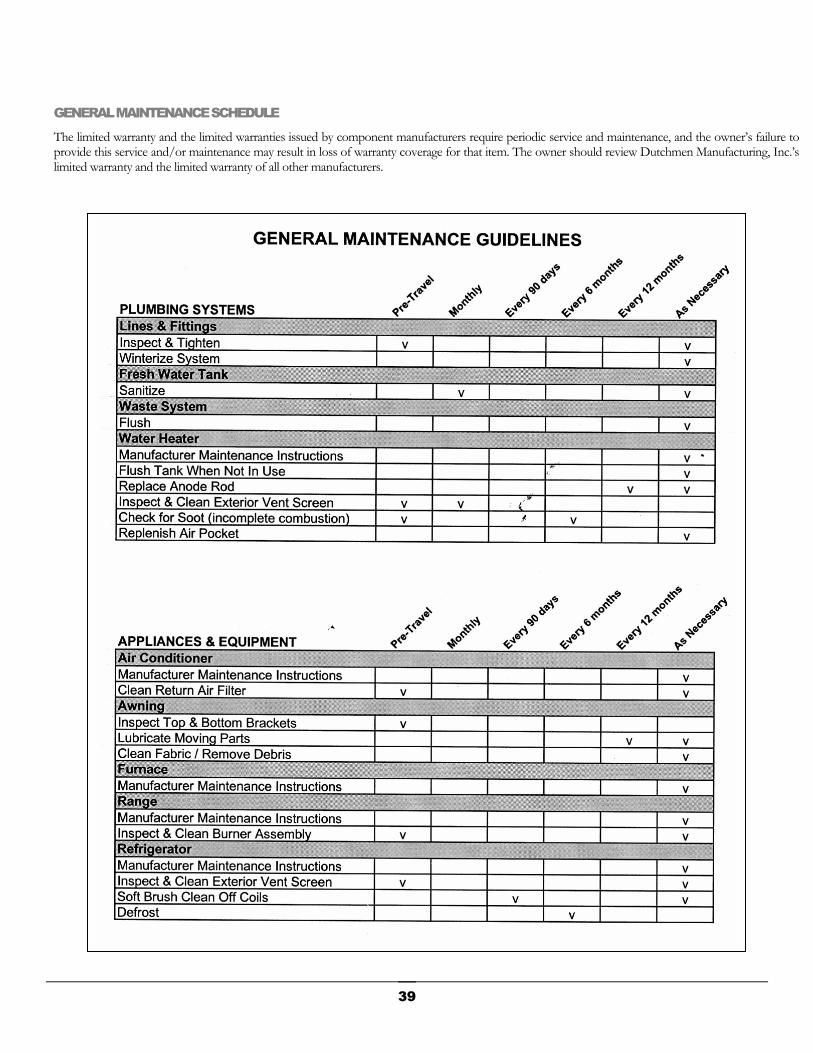
GENERAL MAINTENANCE SCHEDULE
The limited warranty and the limited warranties issued by component manufacturers require periodic service and maintenance, and the owner’s failure to provide this service and/or maintenance may result in loss of warranty coverage for that item. The owner should review Dutchmen Manufacturing, Inc.’s limited warranty and the limited warranty of all other manufacturers.
39
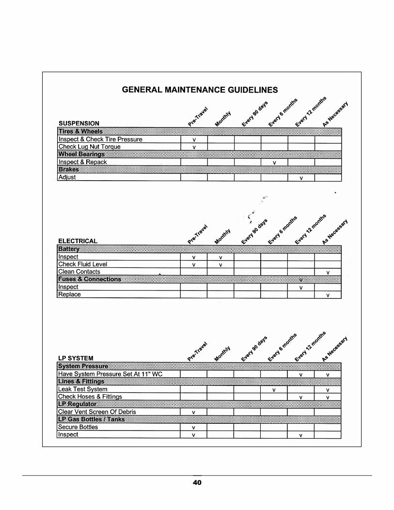
40
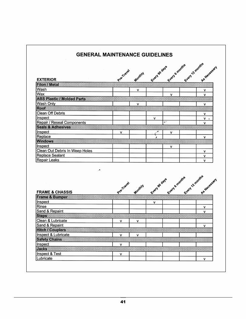
41

MAINTENANCE & SERVICE RECORDS
The limited warranty and the limited warranties issued by component manufacturers require periodic service and maintenance, and the owner’s failure to provide this service and/or maintenance may result in loss of warranty coverage for that item. The owner should review Dutchmen Manufacturing, Inc.’s limited warranty and the limited warranty of all other manufacturers.
42