Embed Size (px)
Citation preview
NASA Technical Memorandum 107378
o _ _ .-.5>72---
Wheel Abrasion Experiment Metals Selectionfor Mars Pathfinder Mission
Aloysius F. HeppLewis Research Center
Cleveland, Ohio
Navid S. Fatemi
Essential Research, Inc.
Cleveland, Ohio
David M. Wilt and Dale C. FergusonLewis Research Center
Cleveland, Ohio
Richard W. Hoffman
Essential Research, Inc.
Cleveland, Ohio
Mafia M. Hill
Kent State University
Kent, Ohio
Alain E. Kaloyeros
State University of New York at Albany
Albany, New York
Prepared for the
1996 Fall Meeting
sponsored by the Materials Research Society
Boston, Massachusetts, December 2-6, 1996
National AeronauticsandSpace Administration
https://ntrs.nasa.gov/search.jsp?R=19970009404 2018-06-13T12:50:29+00:00Z

WHEEL ABRASION EXPERIMENT METALS
SELECTION FOR MARS PATHFINDER MISSION
ALOYSIUS F. HEPP*, NAVID S. FATEMI**, DAVID M. WILT*, DALE C. FERGUSON*,RICHARD W. HOFFMAN**, MARIA M. HILL* AND ALAIN E. KALOYEROS**
*NASA Lewis Research Center, M.S. 302-1, Cleveland, OH 44135; **Essential Research, Inc.,
23811 Chagrin Blvd., Suite 220, Cleveland, OH 44122; *Kent State University; School of Technol-
ogy; Kent, OH 44242; **University at Albany - SUNY, Department of Physics, 1400 Washington
Avenue, Albany, NY 12222
ABSTRACT
A series of metals was examined for suitability for the Wheel Abrasion Experiment, one of ten
microrover experiments of the Mars Pathfinder Mission. The seven candidate metals were: Ag, Al,Au, Cu, Ni, Pt, and W. Thin films of candidate metals from 0.1 to 1.0 micrometer thick were
deposited on black anodized aluminum coupons by e-beam and resistive evaporation and chemical
vapor deposition. Optical, corrosion, abrasion, and adhesion criteria were used to select A1, Ni, and
Pt. A description is given of the deposition and testing of thin films, followed by a presentation of
experimental data and a brief discussion of follow-on testing and flight qualification.
INTRODUCTION
After a twenty-year hiatus [1 ], the United States will return to the surface of Mars with theDecember 1996 launch of the Mars Pathfinder Mission, the second launch in the NASA Discovery
Program. The mission will focus on the demonstration of key technologies and concepts for even-tual use in future missions to Mars that employ scientific landers. Pathfinder will land several
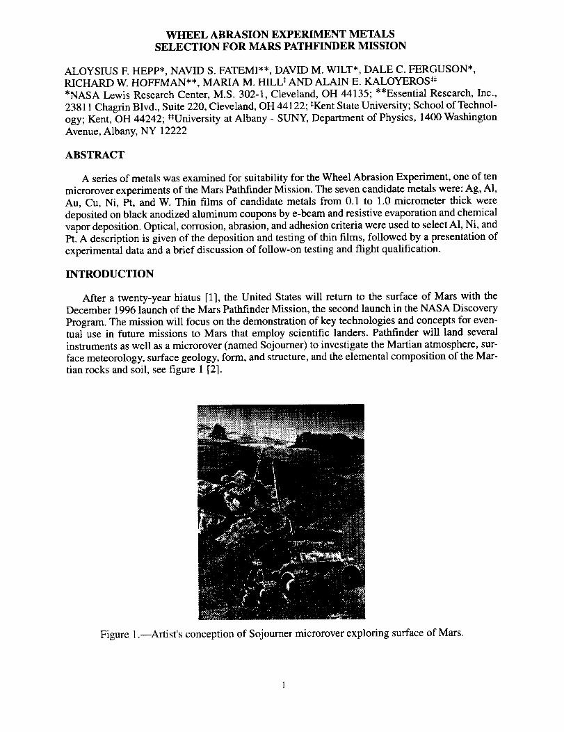
instruments as well as a microrover (named Sojourner) to investigate the Martian atmosphere, sur-
face meteorology, surface geology, form, and structure, and the elemental composition of the Mar-
tian rocks and soil, see figure 1 [2].
Figure 1.--Artist's conception of Sojourner microrover exploring surface of Mars.
While it isdoubtfulthatanynewlight will beshedonthepossibilitythatcarbon-basedlife mayhaveor currentlydoesexistonMars,therecentannouncementandpublicationof evidenceindica-tive of ancientprimitive life on Mars [3] increasedinterestin theMars PathfinderMissionby afactor of five [4]. After the July 1997 landing, the microrover will be deployed to explore the
Martian surface. The Sojourner is equipped with ten experiments, three of which were designed
and built at NASA Lewis Research Center. The purpose of one of these, the Wheel Abrasion
Experiment (WAE) is to determine the mechanical properties of Martian dust and its ability to wear
metal surfaces such as those found in propulsion, structural, and power systems. The wear is to be
detected by a photocell through reduction of reflectance of thin metal films on a black substrate(attached to a microrover wheel) as the wheel rolls over the surface of Mars.
A series of metals was examined for suitability for the WAE. The seven candidate metals were:
Ag, A1, Au, Cu, Ni, Pt, and W. Thin films of candidate metals from 0.1 to 1.0 micrometer thick were
deposited on black anodized aluminum coupons by e-beam and resistive evaporation and chemicalvapor deposition. Optical, corrosion, abrasion, and adhesion criteria were used to select AI, Ni, and
Pt. A description is given of the deposition and testing of thin films, followed by a presentation ofexperimental data and a brief discussion of follow-on testing and flight qualification.
EXPERIMENTAL
The coupons used for reflectance measurements were 0.3 x 1.0 x 6.0 cm 6061-T6 aluminum
that were black anodized according to specification MIL-A-8625-F, resulting in an alumina surface
impregnated with black dye. Ag, A1, Au, Ni, and Pt were deposited by e-beam or resistive evapora-
tion [5]. Chemical vapor deposition of Cu and W were accomplished on custom made systems asdescribed previously [6]. Reflectance measurements were made on a Perkin Elmer Lambda
19 spectrophotometer (equipped with an integrating sphere to capture all reflected light). Metalfilms varied in thickness from 0.1 to 1.0 micrometer.
RESULTS AND DISCUSSION
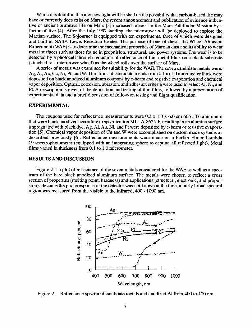
Figure 2 is a plot of reflectance of the seven metals considered for the WAE as well as a spec-trum of the bare black anodized aluminum surface. The metals were chosen to reflect a cross
section of properties (melting point, hardness) and applications (structural, electronic, and propul-
sion). Because the photoresponse of the detector was not known at the time, a fairly broad spectralregion was measured from the visible to the infrared, 400 - 1000 nm.
100
80
60_L
4o
_ 20
p ,P ., -" *_" --_- ..'. ....... Al .,
L- .... ,. pL i ......
.... -: - .,_-
_ _ °°
Au W Z ........ ,,,--- ..................----'''''''',.
/"
0 ....... ..... t..... "1' I I I400 500 600 700 800 900 1000
Wavelength, nm
Figure 2.--Reflectance spectra of candidate metals and anodized AI from 400 to 100 nm.
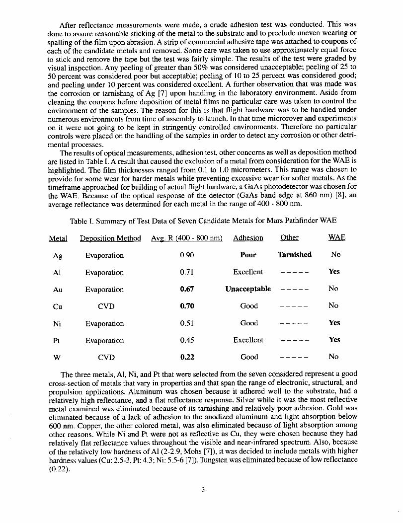
After reflectancemeasurementsweremade,a crudeadhesiontestwasconducted.This wasdoneto assurereasonablestickingof themetalto thesubstrateandto precludeunevenwearingorspallingof thefilm uponabrasion.A stripof commercialadhesivetapewasattachedto couponsofeachof thecandidatemetalsandremoved.Somecarewastakento useapproximatelyequalforceto stick andremovethetapebut thetestwasfairly simple.Theresultsof thetestweregradedbyvisualinspection.Any peelingof greaterthan50%wasconsideredunacceptable;peelingof 25 to50percentwasconsideredpoorbut acceptable;peelingof 10to 25percentwasconsideredgood;andpeelingunder10percentwasconsideredexcellent.A furtherobservationthat wasmadewasthe corrosionor tarnishingof Ag [7] uponhandlingin the laboratoryenvironment.Aside fromcleaningthecouponsbeforedepositionof metalfilms no particularcarewastakento control theenvironmentof thesamples.Thereasonfor this is that flight hardwarewasto behandledundernumerousenvironmentsfromtimeof assemblyto launch.In thattimemicroroverandexperimentson it werenot going to bekept in stringentlycontrolledenvironments.Thereforeno particularcontrolswereplacedon thehandlingof thesamplesin orderto detectanycorrosionor otherdetri-mentalprocesses.
Theresultsof opticalmeasurements,adhesiontest,otherconcernsaswell asdepositionmethodarelistedin TableI. A resultthatcausedtheexclusionof ametalfromconsiderationfor theWAE ishighlighted.The film thicknessesrangedfrom 0.1to 1.0micrometers.This rangewaschosentoprovidefor somewearfor hardermetalswhilepreventingexcessivewearfor softermetals.As thetimeframeapproachedfor buildingof actualflight hardware,aGaAsphotodetectorwaschosenfortheWAE. Becauseof the optical responseof thedetector(GaAsbandedgeat 860 nm) [8], anaveragereflectancewasdeterminedfor eachmetalin therangeof 400- 800nm.
TableI. Summaryof TestDataof SevenCandidateMetalsfor Mars PathfinderWAE
Metal Deposition Method Avg. R (400 - 800 nm) Adhesion Other WAE
Ag Evaporation 0.90 Poor Tarnished No
A1 Evaporation 0.71 Excellent Yes
Au Evaporation 0.67 Unacceptable No
Cu CVD 0.70 Good No
Ni Evaporation 0.51 Good Yes
Pt Evaporation 0.45 Excellent Yes
W CVD 0.22 Good No
The three metals, A1, Ni, and Pt that were selected from the seven considered represent a good
cross-section of metals that vary in properties and that span the range of electronic, structural, and
propulsion applications. Aluminum was chosen because it adhered well to the substrate, had arelatively high reflectance, and a flat reflectance response. Silver while it was the most reflective
metal examined was eliminated because of its tarnishing and relatively poor adhesion. Gold waseliminated because of a lack of adhesion to the anodized aluminum and light absorption below
600 nm. Copper, the other colored metal, was also eliminated because of light absorption amongother reasons. While Ni and Pt were not as reflective as Cu, they were chosen because they had
relatively fiat reflectance values throughout the visible and near-infrared spectrum. Also, because
of the relatively low hardness of A1 (2-2.9, Mohs [7]), it was decided to include metals with higher
hardness values (Cu: 2.5-3, Pt: 4.3; Ni: 5.5-6 [7]). Tungsten was eliminated because of low reflectance
(0.22).
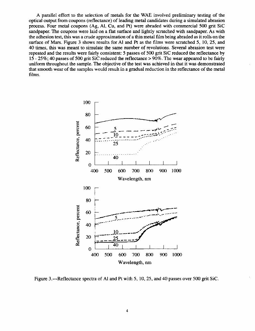
A parallel effort to the selection of metals for the WAE involved preliminary testing of the
optical output from coupons (reflectance) of leading metal candidates during a simulated abrasion
process. Four metal coupons (Ag, AI, Cu, and Pt) were abraded with commercial 500 grit SiC
sandpaper. The coupons were laid on a flat surface and lightly scratched with sandpaper. As with
the adhesion test, this was a crude approximation of a thin metal film being abraded as it rolls on the
surface of Mars. Figure 3 shows results for A1 and Pt as the films were scratched 5, 10, 25, and40 times, this was meant to simulate the same number of revolutions. Several abrasion test were
repeated and the results were fairly consistent: 5 passes of 500 grit SiC reduced the reflectance by
15 - 25%; 40 passes of 500 grit SiC reduced the reflectance > 90%. The wear appeared to be fairly
uniform throughout the sample. The objective of the test was achieved in that it was demonstrated
that smooth wear of the samples would result in a gradual reduction in the reflectance of the metalfilms.
100 -
80
60
t_
40
- 5 ._. _..,_-- ,- ..-.-7::
20 -- .."40
o I l I I I I400 500 600 700 800 900 1000
Wavelength, nm
100
80
u 60
40
0
400
- 25 ....I 4° I I I I I
500 600 700 800 900 1000
Wavelength, nm
Figure 3.--Reflectance spectra of AI and Pt with 5, 10, 25, and 40 passes over 500 grit SiC.
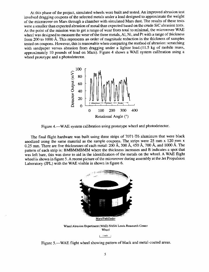
At this phase of the project, simulated wheels were built and tested. An improved abrasion test
involved dragging coupons of the selected metals under a load designed to approximate the weightof the microrover on Mars through a chamber with simulated Mars dust. The results of these tests
were a smaller than expected abrasion of metal than expected based on the crude SiC abrasion tests.
As the point of the mission was to get a range of wear from total to minimal, the microrover WAE
wheel was designed to measure the wear of the three metals, A1, Ni, and Pt with a range of thicknessfrom 200 to 1000 A. This represents an order of magnitude reduction in the thickness of samples
tested on coupons. However, this is reasonable when comparing the method of abrasion: scratching
with sandpaper versus abrasion from dragging under a lighter load.(ll.5 kg of mobile mass,
approximately 10 pounds of load on Mars). Figure 4 shows a WAE system calibration using a
wheel prototype and a photodetector.
100
>E 80
_ 60
© 40O
_ 20
_ 0- Aluminum--+- Platinum _ Nickel ------I
I I I I I t I I
0 100 200 300
Rotational Angle (o)
I
400
Figure 4.--WAE system calibration using prototype wheel and photodetector.
The final flight hardware was built using three strips of 707 l-T6 aluminum that were black
anodized using the same material as the sample coupons. The strips were 25 mm x 120 mm x0.25 mm. There are five thicknesses of each metal: 200 ,_, 300/_, 450/k, 700/_, and 1000 ,_. The
pattern of each strip is: BMBMMBMM where the thickness increases and B indicates a spot thatwas left bare, this was done to aid in the identification of the metals on the wheel. A WAE flight
wheel is shown in figure 5. A recent picture of the microrover during assembly at the Jet Propulsion
Laboratory (JPL) with the WAE visible is shown in figure 6.
Mars/Pathfinder
Wheel Abrasion Experiment (WAE) NASA Lewis Reasearch Center
Wheel
Figure 5.--WAE flight wheel showing pattern of black and metal-coated areas.
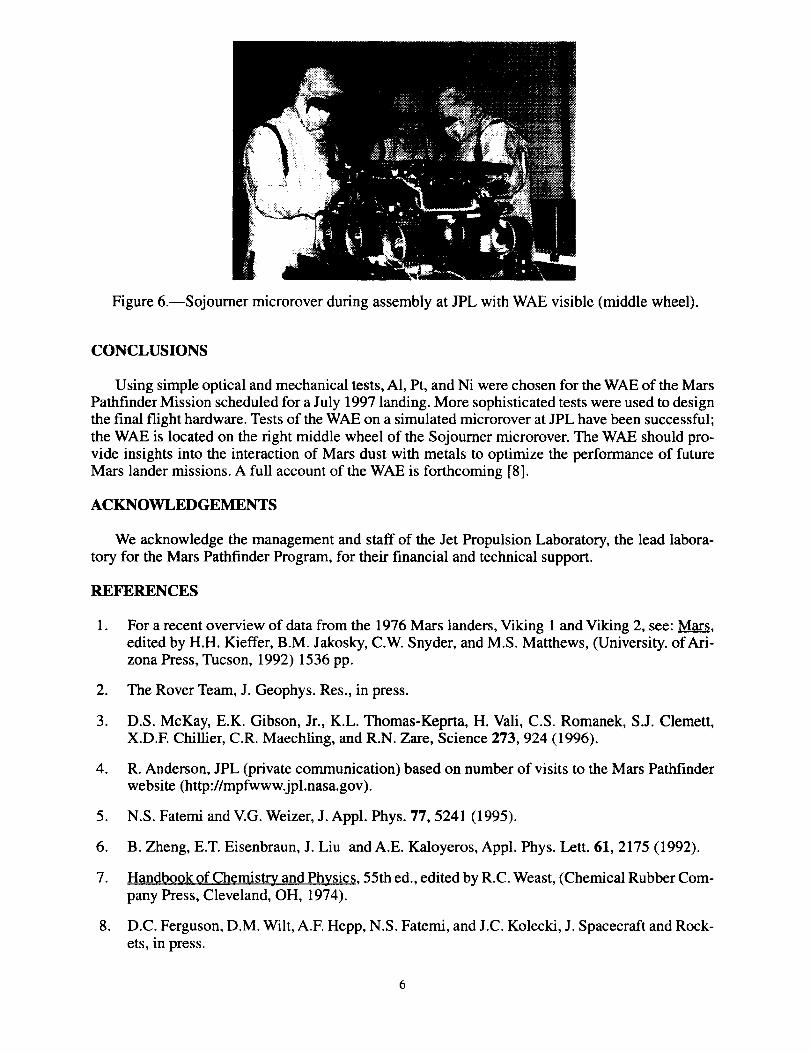
Figure 6.--Sojourner microrover during assembly at JPL with WAE visible (middle wheel).
CONCLUSIONS
Using simple optical and mechanical tests, A1, Pt, and Ni were chosen for the WAE of the Mars
Pathfinder Mission scheduled for a July 1997 landing. More sophisticated tests were used to designthe final flight hardware. Tests of the WAE on a simulated microrover at JPL have been successful;
the WAE is located on the right middle wheel of the Sojourner microrover. The WAE should pro-
vide insights into the interaction of Mars dust with metals to optimize the performance of future
Mars lander missions. A full account of the WAE is forthcoming [8].
ACKNOWLEDGEMENTS
We acknowledge the management and staff of the Jet Propulsion Laboratory, the lead labora-
tory for the Mars Pathfinder Program, for their financial and technical support.
REFERENCES
. For a recent overview of data from the 1976 Mars landers, Viking 1 and Viking 2, see: Mars,
edited by H.H. Kieffer, B.M. Jakosky, C.W. Snyder, and M.S. Matthews, (University. of Ari-zona Press, Tucson, 1992) 1536 pp.
2. The Rover Team, J. Geophys. Res., in press.
3. D.S. McKay, E.K. Gibson, Jr., K.L. Thomas-Keprta, H. Vali, C.S. Romanek, S.J. Clemett,X.D.E Chillier, C.R. Maechling, and R.N. Zare, Science 273, 924 (1996).
4. R. Anderson, JPL (private communication) based on number of visits to the Mars Pathfinder
website (http://mpfwww.jpl.nasa.gov).
5. N.S. Fatemi and V.G. Weizer, J. Appl. Phys. 77, 5241 (1995).
6. B. Zheng, E.T. Eisenbraun, J. Liu and A.E. Kaloyeros, Appl. Phys. Lett. 61, 2175 (1992).
7. Handbook of Chemistry and Physics, 55th ed., edited by R.C. Weast, (Chemical Rubber Com-
pany Press, Cleveland, OH, 1974).
8. D.C. Ferguson, D.M. Wilt, A.E Hepp, N.S. Fatemi, and J.C. Kolecki, J. Spacecraft and Rock-
ets, in press.
Mars Pathfinder Fact Sheet
Mission Summary
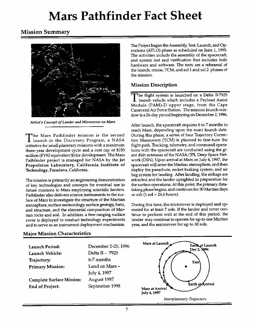
Artist's Concept of Lander and Microrover on Mars
he Mars Pathfinder mission is the secondlaunch in the Discovery Program, a NASA
initiative for small planetary missions with a maximum
three-year development cycle and a cost cap of $150
million (FY92 equivalent $) for development. The Mars
Pathfinder project is managed for NASA by the Jet
Propulsion Laboratory, California Institute of
Technology, Pasadena, California.
The mission is primarily an engineering demonstration
of key technologies and concepts for eventual use infuture missions to Mars employing scientific landers.Pathfinder also delivers science instruments to the sur-
face of Mars to investigate the structure of the Martian
atmosphere, surface meteorology, surface geology, form,and structure, and the elemental composition of Mar-
tian rocks and soil. In addition, a free-ranging surface
rover is deployed to conduct technology experimentsand to serve as an instrument deployment mechanism.
Major Mission Characteristics
Launch Period:
Launch Vehicle:
Trajectory:
Primary Mission:
Complete Surface Mission:
End of Project:
December 2-25, 1996
Delta II - 7925
6-7 months
Land on M.ars -
July 4, 1997
August 1997
September 1998
The Project began the Assembly, Test, Launch, and Op-erations (ATLO) phase as scheduled on June 1, 1995.
The activities include the assembly of the spacecraft,
and system test and verification that includes bothhardware and software. The tests are a rehearsal of
the launch, cruise, TCM, and sol I and sol 2 phases ofthe mission.
Mission Description
he flight system is launched on a Delta 11-7925launch vehicle which includes a Payload Assist
Module (PAM)-D upper stage, from the CapeCanaveral Air Force Station. The mission launch win-
dow is a 24-day period beginning on December 2,1996.
After launch, the spacecraft requires 6 to 7 months to
reach Mars, depending upon the exact launch date.
During this phase, a series of four Trajectory Correc-
tion Maneuvers (TCM) is planned to fine-tune the
flight path. Tracking, telemetry, and command opera-tions with the spacecraft are conducted using the gi-
ant dish antennas of the NASA/JPL Deep Space Net-
work (DSN). Upon arrival at Mars on July 4,1997, the
spacecraft will enter the Martian atmosphere, and then
deploy the parachute, rocket braking system, and air
bag system for landing. After landing, the airbags areretracted and the lander uprighted in preparation for
the surface operations. At this point, the primary data-
taking phase begins, and continues for 30 Martian days
or sols (1 sol = 24.6 hours).
During this time, the microrover is deployed and op-erated for at least 7 sols. If the lander and rover con-
tinue to perform well at the end of this period, the
lander may continue to operate for up to one Martian
year, and the microrover for up to 30 sols.
Mars at ch
Mars at ArrivalJuly 4, 1997
Interplanetary Trajectory
Spacecraft Characteristics/Statistics
Alpha Proton X-ray Spectrometer (mounted to Microrover)
_---- Imager
Microrover Ill" Low Gain Antenna, .... I II / High Gain Antenna
/_ Base Petal
I
"_'m_'q_tmoe pheric ScienceInstrument/Meteorology
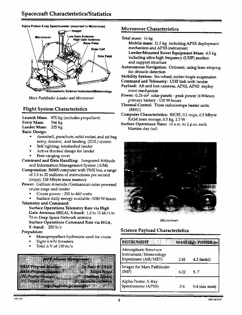
Mars Pathfinder Lander and Microrover
Flight System Characteristics
Launch Mass: 870 kg (includes propellant)
Entry Mass: 566 kg
Lander Mass: 325 kg
Basic Design:
• Aeroshell, parachute, solid rocket, and air bag
entry, descent, and landing (EDL) system
• Self righting, tetrahedral lander
• Active thermal design for lander
• Free-ranging rover
Command and Data Handling: Integrated Attitude
and Information Management System (AIM)
Computation: R6000 computer with VME bus, a range
of 2.5 to 20 millions of instructions per second
(mips), 128 Mbyte mass memory
Power:. Gallium Arsertide / Germanium solar-powered
cruise stage and lander• Cruise power - 250 to 460 watts
• Surface daily energy available -1080 W-hours
Telemetry and Command:
Surface Operations Telemetry Rate via HighGain Antenna (HGA), X-band: 1.2 to 12 kb/s to
70-m Deep Space Network antenna
Surface Operations Command Rate via HGA,X-band: 250b/s
Propulsion:
• MonopropeUant hydrazine used for cruise
• Eight 4.4-N thrusters• Total A V of 130 m/s
_3,_:._iG_- _: " • " " : ........ _ _i _J _ : '
Microrover Characteristics
Total mass: 16 kg
Mobile mass: 11.5 kg including APXS deploymentmechanism and APXS instrument
Lander-Mounted Rover Equipment Mass: 4.5 kg
including ultra-high frequency (UHF) modemand support structure
Autonomous Navigation: Onboard, using laser stripingfor obstacle detection
Mobility System: Six-wheel, rocker-bogie suspension
Command and Telemetry: UHF link with lander
Payload: Aft and fore cameras, APXS, APXS deployment mechanism
Power:. 0.25-m 2 solar panels - peak power 16 W-hours;primary battery - 150 W-hours
Thermal Control: Three radioisotope heater units(RHU)
Computer Characteristics: 80C85, 0.1 mips, 0.5 Mbyte
RAM mass storage, 0.5 kg, 1.5 WSurface Operations Time: 10 a.m. to 2 p.m. each
Martian day (sol)
Microrover
Science Payload Characteristics
Almospheric Structure
Instrument/Meteorology
Experiment (ASI/MET) 2.41 4.2 (lan(_l)
Imager for Mars Pathfinder(IMP) 6.22 5.7
Alpha-Proton X-Ray
Spectrometer (APXS) .5 6 0.4 (data mode)
400.538 8 SMR 0t_28,_5

Form Approved
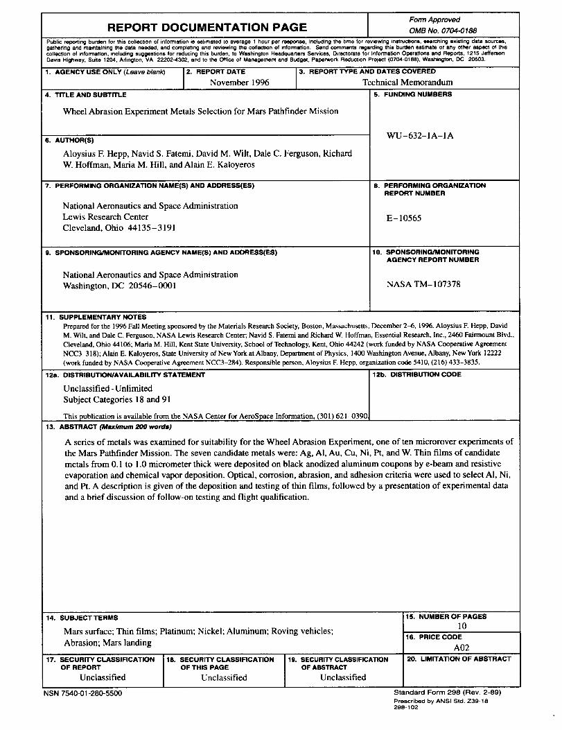
REPORT DOCUMENTATION PAGE OMB No. 0704-0188
Public reporting burden for this collection of information is estimated to average 1 hour per response, including the brae for reviewing instructions, searching existing deta sources,
gathering and maintaining the data needed, and completing and reviewing the collection of information. Send comments regarding this burden estimate or any other aspect of this
collection of information, including suggestions for reducing this burden, to Washington Headqtmrters Services, Directorate for Information Operations and Reports, 1215 Jefferson
Davis Highway, Suite 1204, Arlington, VA 22202-4302, and to the Office of Management end Budget, Paperwork Reduction Project (0704-0188), Washington, DC 20503.
1. AGENCY USE ONLY (Leave blank) 2. REPORT DATE 3. REPORT TYPE AND DATES COVERED
November 1996 Technical Memorandum
4. TITLE AND SUBTITLE
Wheel Abrasion Experiment Metals Selection for Mars Pathfinder Mission
6. AUTHOR(S)
Aloysius F. Hepp, Navid S. Fatemi, David M. Wilt, Dale C. Ferguson, Richard
W. Hoffman, Maria M. Hill, and Alaln E. Kaloyeros
7. PERFORMING ORGANIZATION NAME(S) AND ADDRESS(ES)
National Aeronautics and Space Administration
Lewis Research Center
Cleveland, Ohio 44135-3191
9. SPONSORING/MONITORING AGENCY NAME(S) AND ADDRESS(ES)
National Aeronautics and Space Administration
Washington, DC 20546-0001
5. FUNDING NUMBERS
WU-632-1A-1A
8. PERFORMING ORGANIZATION
REPORT NUMBER
E-10565
10. SPONSORING/MONITORINGAGENCY REPORT NUMBER
NASA TM- 107378
11. SUPPLEMENTARY NOTES
Prepared for the 1996 Fall Meeting sponsored by the Materials Research Society, Boston, Massachusetts December 2-6, 1996. Aloysius E Hepp, David
M. Wilt, and Dale C. Ferguson, NASA Lewis Research Center; Navid S. Fatemi and Richard W. Hoffman Essential Research, Inc., 2460 Fairmount Blvd.,
Cleveland, Ohio 44106; Maria M. Hill, Kent State University, School of Technology, Kent, Ohio 44242 (work funded by NASA Cooperative Agreement
NCC3-318); Alaln E. Kaloyeros, State University of New York at Albany, Department of Physics, 1400 Washington Avenue, Albany, New York 12222
(work funded by NASA Cooperative Agreement NCC3-284). Responsible person, Aloysius F. Hepp, organization code 5410, (216) 433-3835.
12=1. DISTRIBUTION/AVAILABILITY STATEMENT 12b. DISTRIBUTION CODE
Unclassified - Unlimited
Subject Categories 18 and 91
This publication is available from the NASA Center for AeroSpace Information, (301 ) 621-0390
13. ABSTRACT (Maximum 200 words)
A series of metals was examined for suitability for the Wheel Abrasion Experiment, one of ten microrover experiments of
the Mars Pathfinder Mission. The seven candidate metals were: Ag, AI, Au, Cu, Ni, Pt, and W. Thin films of candidate
metals from 0.1 to 1.0 micrometer thick were deposited on black anodized aluminum coupons by e-beam and resistive
evaporation and chemical vapor deposition. Optical, corrosion, abrasion, and adhesion criteria were used to select AI, Ni,
and Pt. A description is given of the deposition and testing of thin films, followed by a presentation of experimental data
and a brief discussion of follow-on testing and flight qualification.
14. SUBJECT TERMS
Mars surface; Thin films; Platinum; Nickel; Aluminum; Roving vehicles;
Abrasion; Mars landing
17. SECURITY CLASSIFICATIONOF REPORT
Unclassified
18. SECURITY CLASSIFICATIONOF THIS PAGE
Unclassified
NSN 7540-01-280-5500
19. SECURITY CLASSIFICATION
OF ABSTRACT
Unclassified
15. NUMBER OF PAGES
l0
16. PRICE CODE
A02
20. LIMITATION OF ABSTRACT
Standard Form 298 (Rev. 2-89)
Prescribed by ANSI Std. Z39-18
298-102