Embed Size (px)
Citation preview

Peter Juhren Corporate Service Manager
Morrow Equipment Co. L.L.C.
Salem, OR USA
What’s New in
Tower Crane
Standards?
The opinions expressed in this presentation are those of the presenter, Peter Juhren, and not necessarily those of ASME or the B30 safety standard committee
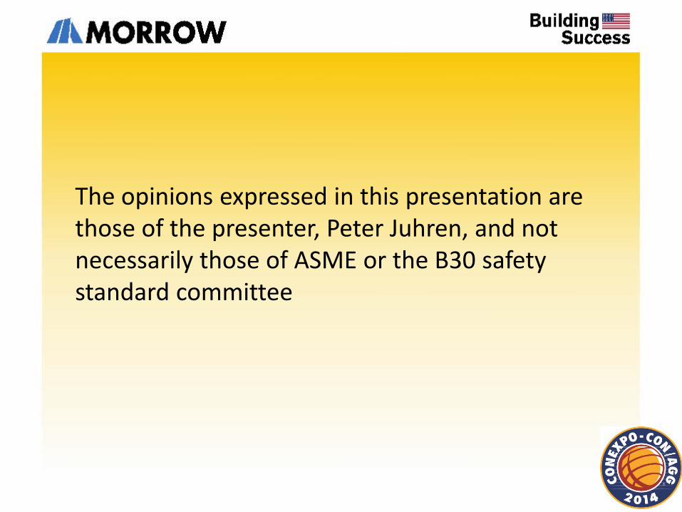
B30.3 Volume applies to “construction tower cranes” and “permanently mounted tower cranes” that are powered by electric motors or internal combustion engines and that adjust their operating radius by means of a luffing boom mechanism, a trolley traversing a horizontal jib, or a combination of the two. The cranes may be mounted on “fixed bases” or “traveling bases” and may have tower and supporting structure arrangements that permit the crane to climb in a structure being built or that permits increasing the crane’s tower height as the structure rises. Variations of the above physical characteristics that provide the same fundamental operating characteristics are included in the scope of this Volume; however, the requirements of this Volume are only applicable to the cranes within this scope when they are used in lifting operations. Mobile cranes configured with tower attachments (refer to ASME B30.5) and self-erecting tower cranes (refer to ASME B30.29) are not within the scope of this Volume.
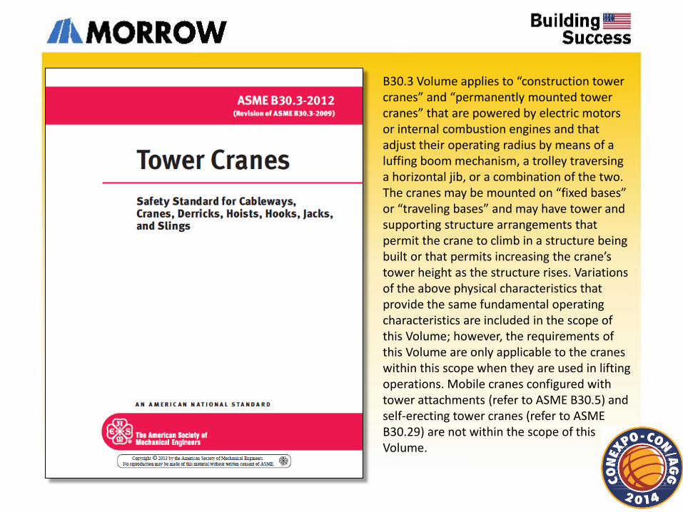
Self-erect tower cranes have vertical or nearly vertical masts that are bottom slewing and mounted on fixed, traveling, or mobile bases. The cranes are capable of moving or being moved from jobsite to jobsite fully assembled or nearly fully assembled. This Volume does not apply to cranes used for non-vertical lifting service or lifting a guided load, or to truck-mounted material delivery cranes with a tubular boom and trolley traversing the boom. Tower cranes (refer to ASME B30.3) and mobile crane tower attachments (refer to ASME B30.5) are not within the scope of this Volume.
ASME B30.3 Tower Cranes
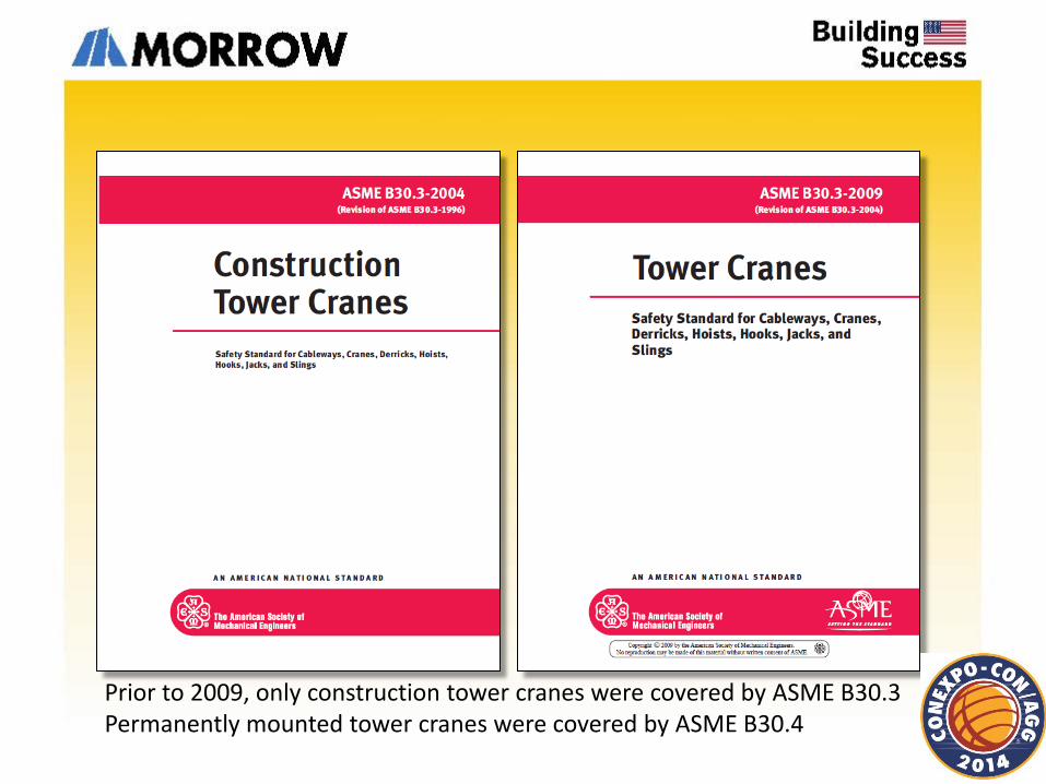
Prior to 2009, only construction tower cranes were covered by ASME B30.3 Permanently mounted tower cranes were covered by ASME B30.4
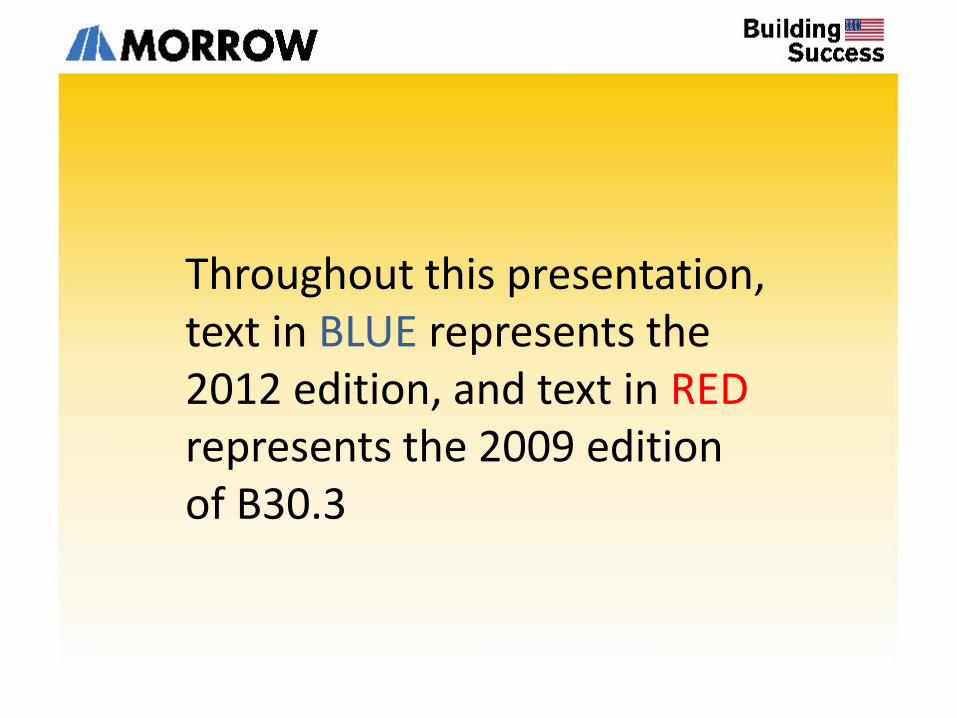
Throughout this presentation, text in BLUE represents the 2012 edition, and text in RED represents the 2009 edition of B30.3
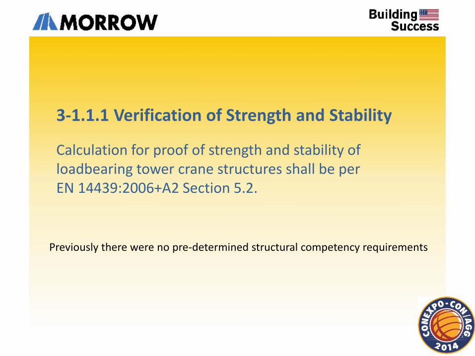
3-1.1.1 Verification of Strength and Stability
Calculation for proof of strength and stability of loadbearing tower crane structures shall be per EN 14439:2006+A2 Section 5.2.
Previously there were no pre-determined structural competency requirements
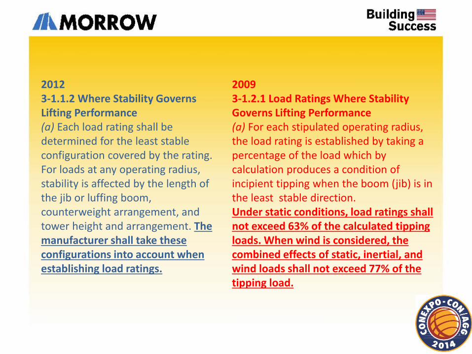
2009 3-1.2.1 Load Ratings Where Stability Governs Lifting Performance (a) For each stipulated operating radius, the load rating is established by taking a percentage of the load which by calculation produces a condition of incipient tipping when the boom (jib) is in the least stable direction. Under static conditions, load ratings shall not exceed 63% of the calculated tipping loads. When wind is considered, the combined effects of static, inertial, and wind loads shall not exceed 77% of the tipping load.
2012 3-1.1.2 Where Stability Governs Lifting Performance (a) Each load rating shall be determined for the least stable configuration covered by the rating. For loads at any operating radius, stability is affected by the length of the jib or luffing boom, counterweight arrangement, and tower height and arrangement. The manufacturer shall take these configurations into account when establishing load ratings.
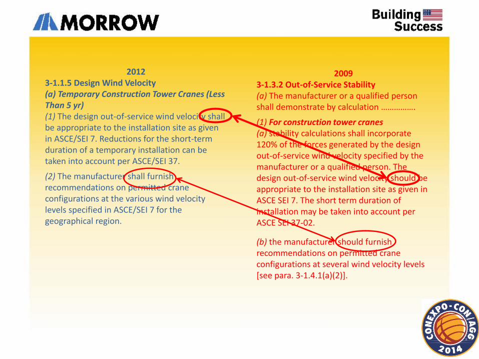
2009 3-1.3.2 Out-of-Service Stability (a) The manufacturer or a qualified person shall demonstrate by calculation …………….
(1) For construction tower cranes (a) stability calculations shall incorporate 120% of the forces generated by the design out-of-service wind velocity specified by the manufacturer or a qualified person. The design out-of-service wind velocity should be appropriate to the installation site as given in ASCE SEI 7. The short term duration of installation may be taken into account per ASCE SEI 37-02.
(b) the manufacturer should furnish recommendations on permitted crane configurations at several wind velocity levels [see para. 3-1.4.1(a)(2)].
2012 3-1.1.5 Design Wind Velocity (a) Temporary Construction Tower Cranes (Less Than 5 yr) (1) The design out-of-service wind velocity shall be appropriate to the installation site as given in ASCE/SEI 7. Reductions for the short-term duration of a temporary installation can be taken into account per ASCE/SEI 37.
(2) The manufacturer shall furnish recommendations on permitted crane configurations at the various wind velocity levels specified in ASCE/SEI 7 for the geographical region.
2009 3-1.3.2 Out-of-Service Stability
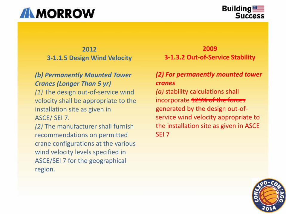
(2) For permanently mounted tower cranes (a) stability calculations shall incorporate 125% of the forces generated by the design out-of-service wind velocity appropriate to the installation site as given in ASCE SEI 7
2012 3-1.1.5 Design Wind Velocity
(b) Permanently Mounted Tower Cranes (Longer Than 5 yr) (1) The design out-of-service wind velocity shall be appropriate to the installation site as given in ASCE/ SEI 7. (2) The manufacturer shall furnish recommendations on permitted crane configurations at the various wind velocity levels specified in ASCE/SEI 7 for the geographical region.
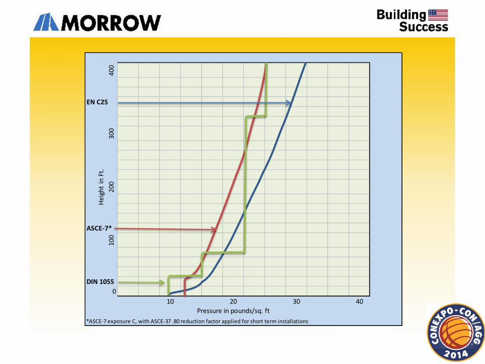
400
EN C25
300
200
ASCE-7*
100
DIN 1055
0
10 20 30 40
*ASCE-7 exposure C, with ASCE-37 .80 reduction factor applied for short term installations
Pressure in pounds/sq. ft
Hei
ght
in F
t.
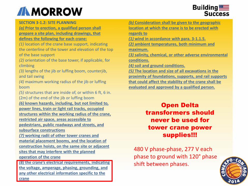
SECTION 3-1.2: SITE PLANNING (a) Prior to erection, a qualified person shall prepare a site plan, including drawings, that defines the following for each crane: (1) location of the crane base support, indicating the centerline of the tower and elevation of the top of the base support (2) orientation of the base tower, if applicable, for climbing (3) lengths of the jib or luffing boom, counterjib, and tail swing (4) maximum working radius of the jib or luffing boom (5) structures that are inside of, or within 6 ft, 6 in. (2m) of the end of the jib or luffing boom (6) known hazards, including, but not limited to, power lines, train or light rail tracks, occupied structures within the working radius of the crane, restricted air space, areas accessible to pedestrians, public roadways and streets, and subsurface constructions (7) working radii of other tower cranes and material placement booms, and the location of construction hoists, on the same site or adjacent sites that may interfere with the planned operation of the crane (8) the crane’s electrical requirements, indicating the voltage, amperage, phasing, grounding, and any other electrical information specific to the crane
(b) Consideration shall be given to the geographic location at which the crane is to be erected with regards to (1) wind in accordance with para. 3-1.1.5. (2) ambient temperatures, both minimum and maximum. (3) salinity, chemical, or other adverse environmental conditions. (4) soil and ground conditions. (5) The location and size of all excavations in the proximity of foundations, supports, and rail supports that could affect the stability of the crane shall be evaluated and approved by a qualified person.
Open Delta
transformers should
never be used for
tower crane power
supplies!!!
480 V phase-phase, 277 V each phase to ground with 120° phase shift between phases.
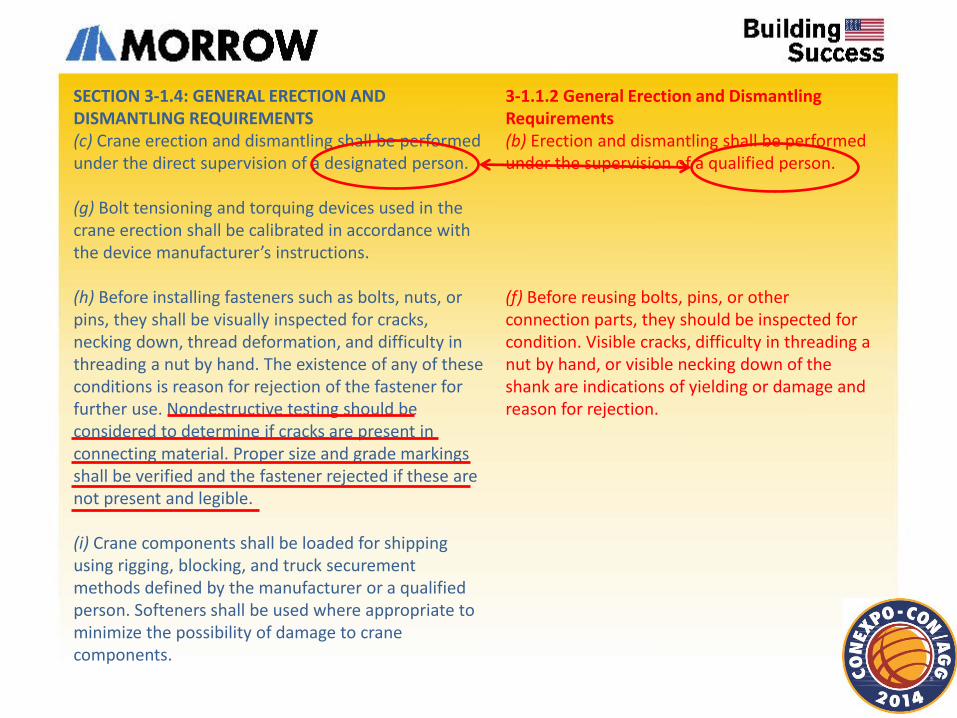
SECTION 3-1.4: GENERAL ERECTION AND DISMANTLING REQUIREMENTS (c) Crane erection and dismantling shall be performed under the direct supervision of a designated person. (g) Bolt tensioning and torquing devices used in the crane erection shall be calibrated in accordance with the device manufacturer’s instructions. (h) Before installing fasteners such as bolts, nuts, or pins, they shall be visually inspected for cracks, necking down, thread deformation, and difficulty in threading a nut by hand. The existence of any of these conditions is reason for rejection of the fastener for further use. Nondestructive testing should be considered to determine if cracks are present in connecting material. Proper size and grade markings shall be verified and the fastener rejected if these are not present and legible. (i) Crane components shall be loaded for shipping using rigging, blocking, and truck securement methods defined by the manufacturer or a qualified person. Softeners shall be used where appropriate to minimize the possibility of damage to crane components.
3-1.1.2 General Erection and Dismantling Requirements (b) Erection and dismantling shall be performed under the supervision of a qualified person. (f) Before reusing bolts, pins, or other connection parts, they should be inspected for condition. Visible cracks, difficulty in threading a nut by hand, or visible necking down of the shank are indications of yielding or damage and reason for rejection.
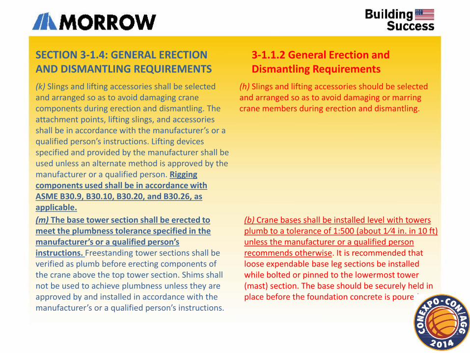
(k) Slings and lifting accessories shall be selected and arranged so as to avoid damaging crane components during erection and dismantling. The attachment points, lifting slings, and accessories shall be in accordance with the manufacturer’s or a qualified person’s instructions. Lifting devices specified and provided by the manufacturer shall be used unless an alternate method is approved by the manufacturer or a qualified person. Rigging components used shall be in accordance with ASME B30.9, B30.10, B30.20, and B30.26, as applicable.
(b) Crane bases shall be installed level with towers plumb to a tolerance of 1:500 (about 1⁄4 in. in 10 ft) unless the manufacturer or a qualified person recommends otherwise. It is recommended that loose expendable base leg sections be installed while bolted or pinned to the lowermost tower (mast) section. The base should be securely held in place before the foundation concrete is poured.
SECTION 3-1.4: GENERAL ERECTION AND DISMANTLING REQUIREMENTS
3-1.1.2 General Erection and Dismantling Requirements
(h) Slings and lifting accessories should be selected and arranged so as to avoid damaging or marring crane members during erection and dismantling.
(m) The base tower section shall be erected to meet the plumbness tolerance specified in the manufacturer’s or a qualified person’s instructions. Freestanding tower sections shall be verified as plumb before erecting components of the crane above the top tower section. Shims shall not be used to achieve plumbness unless they are approved by and installed in accordance with the manufacturer’s or a qualified person’s instructions.
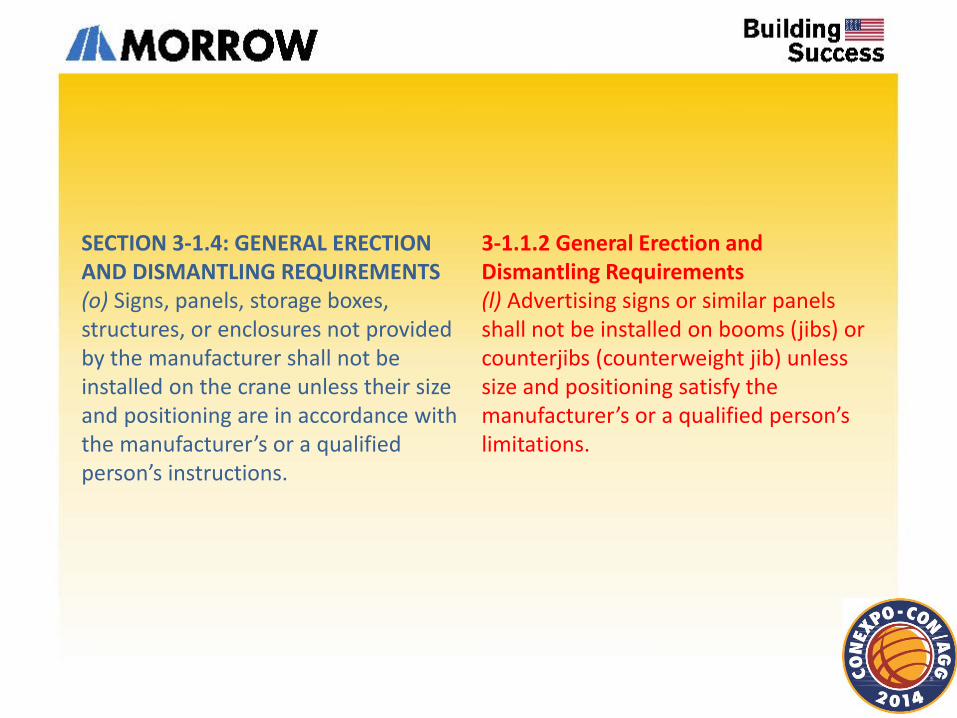
SECTION 3-1.4: GENERAL ERECTION AND DISMANTLING REQUIREMENTS (o) Signs, panels, storage boxes, structures, or enclosures not provided by the manufacturer shall not be installed on the crane unless their size and positioning are in accordance with the manufacturer’s or a qualified person’s instructions.
3-1.1.2 General Erection and Dismantling Requirements (l) Advertising signs or similar panels shall not be installed on booms (jibs) or counterjibs (counterweight jib) unless size and positioning satisfy the manufacturer’s or a qualified person’s limitations.
SECTION 3-1.5: FREESTANDING CRANES
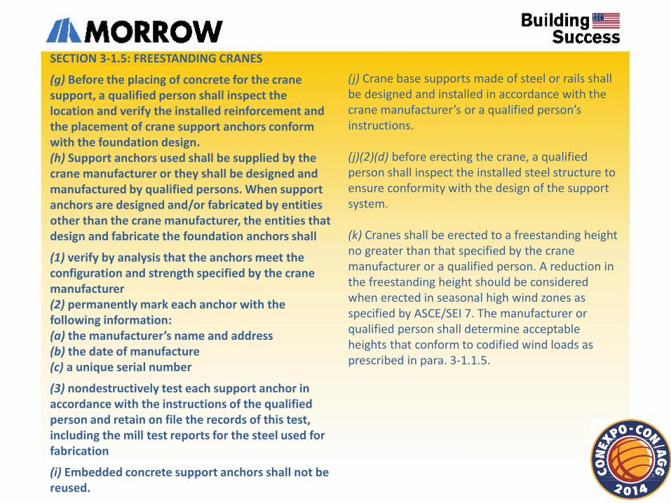
(g) Before the placing of concrete for the crane support, a qualified person shall inspect the location and verify the installed reinforcement and the placement of crane support anchors conform with the foundation design. (h) Support anchors used shall be supplied by the crane manufacturer or they shall be designed and manufactured by qualified persons. When support anchors are designed and/or fabricated by entities other than the crane manufacturer, the entities that design and fabricate the foundation anchors shall
(1) verify by analysis that the anchors meet the configuration and strength specified by the crane manufacturer (2) permanently mark each anchor with the following information: (a) the manufacturer’s name and address (b) the date of manufacture (c) a unique serial number
(3) nondestructively test each support anchor in accordance with the instructions of the qualified person and retain on file the records of this test, including the mill test reports for the steel used for fabrication
(i) Embedded concrete support anchors shall not be reused.
(j) Crane base supports made of steel or rails shall be designed and installed in accordance with the crane manufacturer’s or a qualified person’s instructions. (j)(2)(d) before erecting the crane, a qualified person shall inspect the installed steel structure to ensure conformity with the design of the support system. (k) Cranes shall be erected to a freestanding height no greater than that specified by the crane manufacturer or a qualified person. A reduction in the freestanding height should be considered when erected in seasonal high wind zones as specified by ASCE/SEI 7. The manufacturer or qualified person shall determine acceptable heights that conform to codified wind loads as prescribed in para. 3-1.1.5.
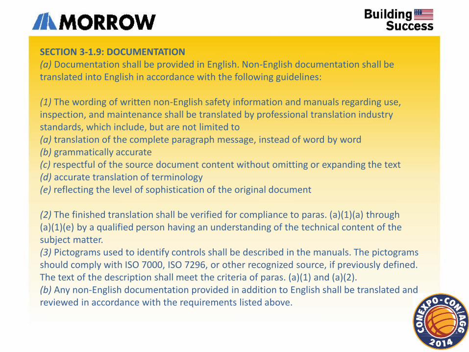
SECTION 3-1.9: DOCUMENTATION (a) Documentation shall be provided in English. Non-English documentation shall be translated into English in accordance with the following guidelines: (1) The wording of written non-English safety information and manuals regarding use, inspection, and maintenance shall be translated by professional translation industry standards, which include, but are not limited to (a) translation of the complete paragraph message, instead of word by word (b) grammatically accurate (c) respectful of the source document content without omitting or expanding the text (d) accurate translation of terminology (e) reflecting the level of sophistication of the original document (2) The finished translation shall be verified for compliance to paras. (a)(1)(a) through (a)(1)(e) by a qualified person having an understanding of the technical content of the subject matter. (3) Pictograms used to identify controls shall be described in the manuals. The pictograms should comply with ISO 7000, ISO 7296, or other recognized source, if previously defined. The text of the description shall meet the criteria of paras. (a)(1) and (a)(2). (b) Any non-English documentation provided in addition to English shall be translated and reviewed in accordance with the requirements listed above.
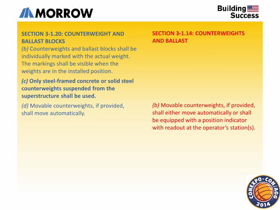
SECTION 3-1.14: COUNTERWEIGHTS AND BALLAST
(b) Movable counterweights, if provided, shall either move automatically or shall be equipped with a position indicator with readout at the operator’s station(s).
SECTION 3-1.20: COUNTERWEIGHT AND BALLAST BLOCKS (b) Counterweights and ballast blocks shall be individually marked with the actual weight. The markings shall be visible when the weights are in the installed position.
(c) Only steel-framed concrete or solid steel counterweights suspended from the superstructure shall be used.
(d) Movable counterweights, if provided, shall move automatically.
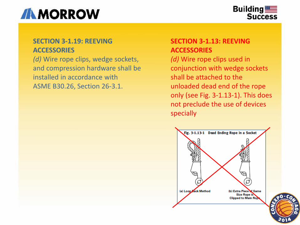
SECTION 3-1.13: REEVING ACCESSORIES (d) Wire rope clips used in conjunction with wedge sockets shall be attached to the unloaded dead end of the rope only (see Fig. 3-1.13-1). This does not preclude the use of devices specially
SECTION 3-1.19: REEVING ACCESSORIES (d) Wire rope clips, wedge sockets, and compression hardware shall be installed in accordance with ASME B30.26, Section 26-3.1.
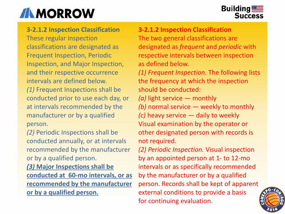
3-2.1.2 Inspection Classification The two general classifications are designated as frequent and periodic with respective intervals between inspection as defined below. (1) Frequent Inspection. The following lists the frequency at which the inspection should be conducted: (a) light service — monthly (b) normal service — weekly to monthly (c) heavy service — daily to weekly Visual examination by the operator or other designated person with records is not required. (2) Periodic Inspection. Visual inspection by an appointed person at 1- to 12-mo intervals or as specifically recommended by the manufacturer or by a qualified person. Records shall be kept of apparent external conditions to provide a basis for continuing evaluation.
3-2.1.2 Inspection Classification These regular inspection classifications are designated as Frequent Inspection, Periodic Inspection, and Major Inspection, and their respective occurrence intervals are defined below. (1) Frequent Inspections shall be conducted prior to use each day, or at intervals recommended by the manufacturer or by a qualified person. (2) Periodic Inspections shall be conducted annually, or at intervals recommended by the manufacturer or by a qualified person. (3) Major Inspections shall be conducted at 60-mo intervals, or as recommended by the manufacturer or by a qualified person.
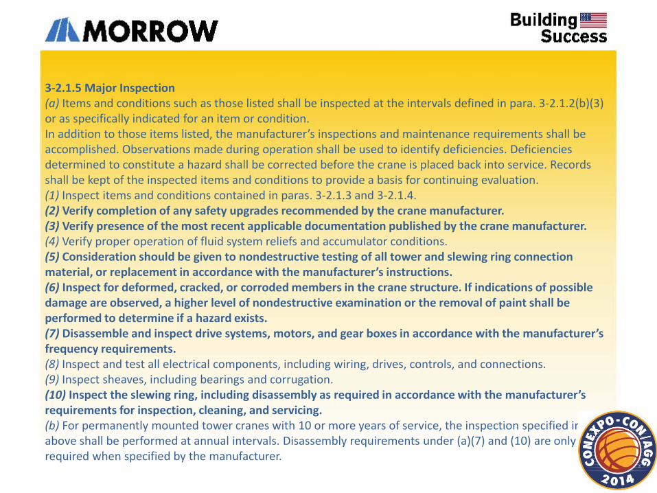
3-2.1.5 Major Inspection (a) Items and conditions such as those listed shall be inspected at the intervals defined in para. 3-2.1.2(b)(3) or as specifically indicated for an item or condition. In addition to those items listed, the manufacturer’s inspections and maintenance requirements shall be accomplished. Observations made during operation shall be used to identify deficiencies. Deficiencies determined to constitute a hazard shall be corrected before the crane is placed back into service. Records shall be kept of the inspected items and conditions to provide a basis for continuing evaluation. (1) Inspect items and conditions contained in paras. 3-2.1.3 and 3-2.1.4. (2) Verify completion of any safety upgrades recommended by the crane manufacturer. (3) Verify presence of the most recent applicable documentation published by the crane manufacturer. (4) Verify proper operation of fluid system reliefs and accumulator conditions. (5) Consideration should be given to nondestructive testing of all tower and slewing ring connection material, or replacement in accordance with the manufacturer’s instructions. (6) Inspect for deformed, cracked, or corroded members in the crane structure. If indications of possible damage are observed, a higher level of nondestructive examination or the removal of paint shall be performed to determine if a hazard exists. (7) Disassemble and inspect drive systems, motors, and gear boxes in accordance with the manufacturer’s frequency requirements. (8) Inspect and test all electrical components, including wiring, drives, controls, and connections. (9) Inspect sheaves, including bearings and corrugation. (10) Inspect the slewing ring, including disassembly as required in accordance with the manufacturer’s requirements for inspection, cleaning, and servicing. (b) For permanently mounted tower cranes with 10 or more years of service, the inspection specified in (a) above shall be performed at annual intervals. Disassembly requirements under (a)(7) and (10) are only required when specified by the manufacturer.
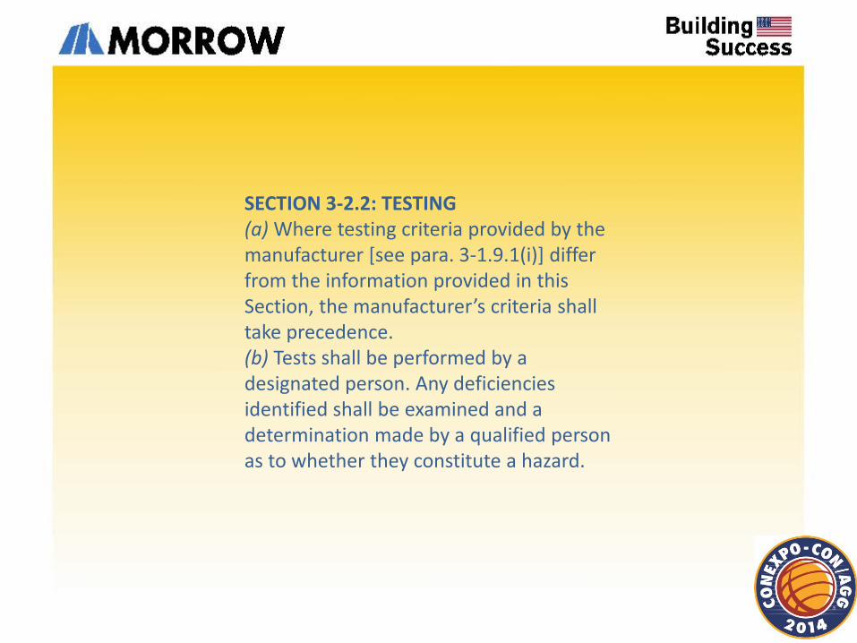
SECTION 3-2.2: TESTING (a) Where testing criteria provided by the manufacturer [see para. 3-1.9.1(i)] differ from the information provided in this Section, the manufacturer’s criteria shall take precedence. (b) Tests shall be performed by a designated person. Any deficiencies identified shall be examined and a determination made by a qualified person as to whether they constitute a hazard.
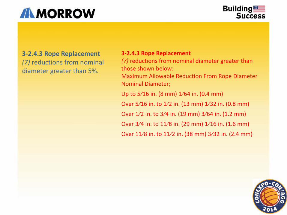
3-2.4.3 Rope Replacement (7) reductions from nominal diameter greater than 5%.
3-2.4.3 Rope Replacement (7) reductions from nominal diameter greater than those shown below: Maximum Allowable Reduction From Rope Diameter Nominal Diameter;
Up to 5⁄16 in. (8 mm) 1⁄64 in. (0.4 mm)
Over 5⁄16 in. to 1⁄2 in. (13 mm) 1⁄32 in. (0.8 mm)
Over 1⁄2 in. to 3⁄4 in. (19 mm) 3⁄64 in. (1.2 mm)
Over 3⁄4 in. to 11⁄8 in. (29 mm) 1⁄16 in. (1.6 mm)
Over 11⁄8 in. to 11⁄2 in. (38 mm) 3⁄32 in. (2.4 mm)
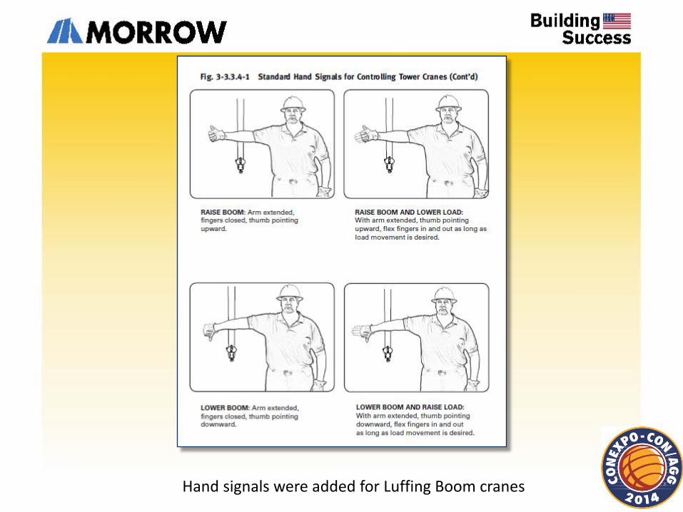
Hand signals were added for Luffing Boom cranes
29-3.1.3 Responsibilities While the organizational structure of various projects may differ, the following roles are described here for purposes of delineating responsibilities. All responsibilities listed below shall be assigned in the worksite organization. (A single individual may perform one or more of these roles.)
(a) Crane Owner. Has custodial control of a crane by virtue of lease or ownership.
(b) Crane User. Arranges the crane’s presence on a worksite and controls its use there.
(c) Site Supervisor. Exercises supervisory control over the worksite on which a crane is being used and over the work that is being performed on that site.
(d) Lift Director. Directly oversees the work being performed by a crane and the associated rigging crew.
(e) Crane Operator. Directly controls the crane’s functions.
ASME B30.29 Self Erecting Tower Cranes
29-1.1.1 Crane Supports (a) Crane supports for individual outrigger pads shall be level in accordance with the manufacturer’s specifications or those of a qualified person. Supports may be individual timbers, mats, or engineered structural supports to distribute the load so as not to exceed the allowable bearing capacity of the underlying material as determined by a qualified person.
29-1.1.2 Erection, Reconfiguring, and Dismantling (a) The area in which a self-erect tower crane is to be installed shall be assessed to ensure that it is suitable before the crane is delivered and put into service. The area chosen shall be of a sufficient size to enable the self-erect tower crane to be maneuvered into position, set up, operated, and dismantled with sufficient clearances between the crane and surrounding structures.
29-1.3.3 Outriggers (a) The manufacturer’s documentation for the crane shall describe the use of outriggers and whether they are required for in-service, out-of-service, or backward stability.
(b) Means shall be provided to hold all outriggers in the retracted position while traveling, and in the extended position when set for operating.
(c) Power-actuated jacks, where used, shall be provided with the means (such as integral load hold check valves on hydraulic cylinders, mechanical locks, etc.) to prevent uncontrolled cylinder movement.
(d) Means shall be provided for fastening outrigger floats to outriggers when in use
29-3.1.4 Operating Practices (a) While using a remote control, the operator shall;
(1) be stationary when any crane function is engaged
(2) deactivate the remote control when changing locations
(3) be in a position to visually verify that actual crane movement corresponds with the remote control function engaged
Develop a 4 step process to improve your operations
Quality Control Quality Assurance Codes and Standards Safety Program
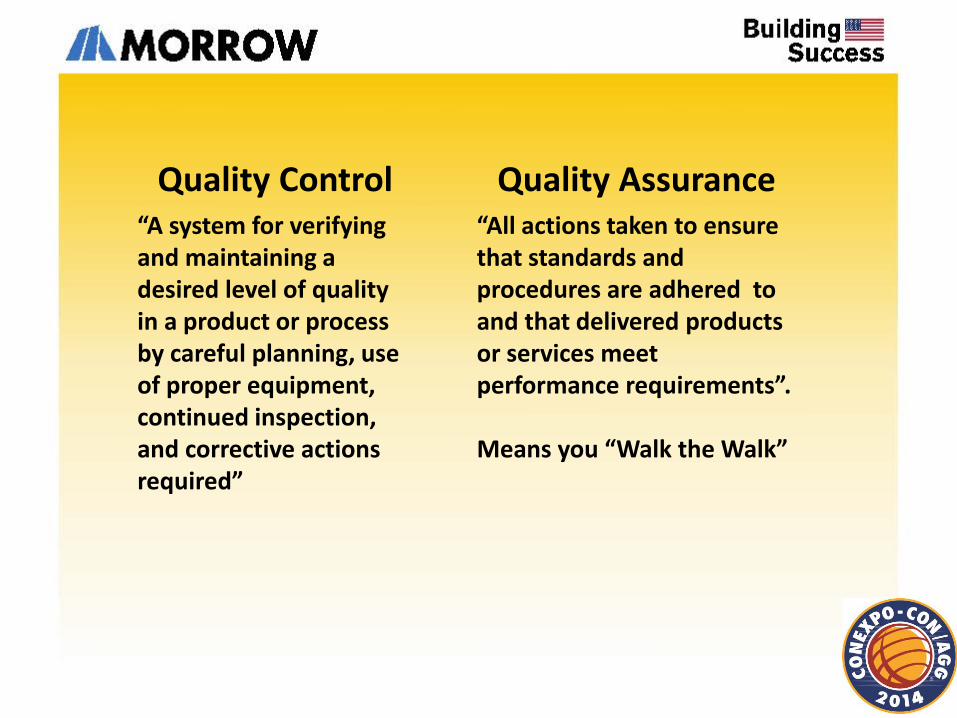
Quality Control “A system for verifying and maintaining a desired level of quality in a product or process by careful planning, use of proper equipment, continued inspection, and corrective actions required”
Quality Assurance “All actions taken to ensure that standards and procedures are adhered to and that delivered products or services meet performance requirements”. Means you “Walk the Walk”
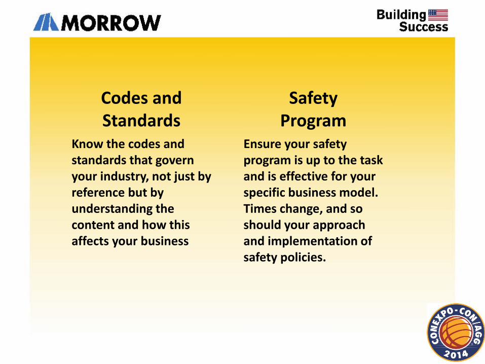
Codes and Standards
Know the codes and standards that govern your industry, not just by reference but by understanding the content and how this affects your business
Safety Program
Ensure your safety program is up to the task and is effective for your specific business model. Times change, and so should your approach and implementation of safety policies.
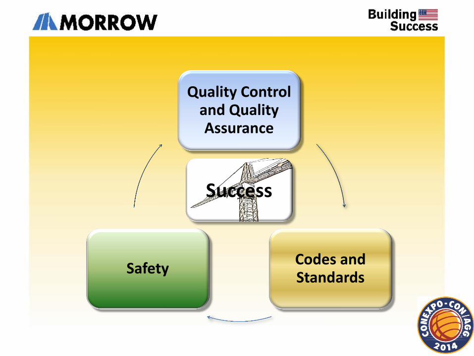
Quality Control and Quality Assurance
Codes and Standards
Safety
Success

Peter Juhren Corporate Service Manager
Morrow Equipment Co. L.L.C.
Salem, OR USA
Thank You


![(]I)@. · PDF filetower crane foundation developed by ... ileigwr relescop tower elements wind 'in service' wind 'outof service' pressure plinth undeh cage quantity and type](https://img.pdfslide.us/doc/110x75/5aa9569e7f8b9a95188cb07e/i-crane-foundation-developed-by-ileigwr-relescop-tower-elements-wind-in.jpg)