Embed Size (px)
Citation preview

MODERN STEEL CONSTRUCTION august 2012
What's Cool in

What's Cool in
Cool Tea HouseInner Peace in a Floating Box
What’s C
ool
What’s Coolin
ThE TypICaL aMERICaN hOME aDDITION might include an add-on room to the back or side of a house, or even an additional floor.
Something like, say, a detached, floating medita-tion and performance space that evokes a Japanese lantern is probably not as common.
But there’s one in Bethesda, Md. The Tea House, designed by David Jameson, Inc., is made from bronze, glass and steel. Situated in a wooded residential backyard in this suburb of Washington, D.C., the structure serves as a tea room, mediation space and stage for the family’s recitals (multiple members of the family are musicians).
As visitors approach the Tea House from the main house, they must walk around the entire structure and are funneled through a curated pro-cession space between strands of bamboo—the intent is to cleanse the mind and prepare one to enter the room—to gain access at the opposite end, via a 4-in.-thick wood door. The 12-ft x 16-ft room is supported by a diamond-shaped Vierendeel truss, which is suspended from two steel moment frames with HSS3x3 hangers. The structure, which uses 1.5 tons of steel in all, was designed to accom-modate a 40-psf residential floor load and 90-mph wind loads. The floor and ceiling framing is made from HSS of various sizes, and the moment frame is made from W18 beams and W12 columns.
The most challenging part of the structural design, performed by Linton Engineering, was to limit lateral deflection (to prevent damage to archi-tectural finishes) while also achieving torsional stability of the steel frame with only one point of structural support at the base of the structure. This was accomplished by developing a series of triangu-lar HSS trusses that cantilevered from an interior concrete pier, which was hidden from view beneath the structure. A supplemental layer of HSS fram-ing was welded to the trusses to create a platform to support the floors and link with the HSS hang-ers, which supported the four corners of the Tea House. The design of the structure was governed by the lateral deflections that occurred under the orthogonal wind load cases.
Linton Engineering
Paul Warchol
Paul Warchol
august 2012 MODERN STEEL CONSTRUCTION

ThE OLyMpIC MOTTO is “Swifter, Higher, Stronger.”And one of the many representations of this motto
at London’s 2012 Olympic and Paralympic Games takes shape in the form of a 376-ft-tall (114.5 m) spiraling red steel sculpture that dominates the East London skyline and offers visitors panoramic views of the city.
The sculpture, the ArcelorMittal Orbit, will house a viewing platform, create 50 new jobs and is expected to generate £10 million ($15.5 million) each year in revenue, continuing the Olympic legacy after the Games close. It’s the tallest sculpture in Britain and harnesses steel sourced from every continent where ArcelorMittal has operations. (As a Tier 2 sponsor of the Games, ArcelorMittal donated £19.6 million [$30.7 million] and the 2,000 tons of steel to create the sculpture.)
Sitting between the Stadium and the Aquatics Centre, it will serve as a beacon of Olympic Park during the Games (and then Queen Elizabeth Olympic Park, as the area will be known after the Games). Construction took 18 months.
Taller than Big Ben and the Statue of Liberty, the design is the largest artistic commission in the world, and was con-ceived and designed by Anish Kapoor and Cecil Balmond. Kapoor, known as one of the world’s leading artists, has been recognized for his use of rich pigment and imposing yet popular works, such as the Cloud Gate in Chicago’s Mil-lennium Park (better known as “The Bean”) and his recent show at the Royal Academy, the most successful exhibition ever presented by a contemporary artist in London.
Balmond is well known for his innovative work on some of the greatest contemporary buildings in the world, such as the CCTV building in Beijing, as well as many Serpentine Gallery Pavilion commissions (visit www.serpentinegallery.org for more information).
“Anish and I were conscious from the beginning that the ArcelorMittal Orbit would be a lasting legacy to the city, and so we wanted to stretch the language of the icon as far as we could go,” said Balmond. “The Orbit is a hybrid, a network of art and structure, and its dynamic is the non-linear. You read into it multiple narratives in space.”
The monument’s steel construction required state-of-the-art engineering and architectural techniques that can withstand London’s weather as well as serve millions of visitors. “The ArcelorMittal Orbit could only be built in steel, to give the minimum thickness and the maximum strength,” explained Balmond. “I didn’t consider any other material because you couldn’t make this coiling structure with anything else.”
Cool Olympic Towerspiraling above LondonBy sunny Oh, ExtErnaL COmmunICatIOns managEr, arCELOrmIttaL
What’s C
ool
What’s Coolin
MODERN STEEL CONSTRUCTION august 2012

august 2012 MODERN STEEL CONSTRUCTION
Visitors will be able to reach the top of the struc-ture via elevator, although they will be encouraged to walk down the spiral staircase, which has 455 steps and has been designed to enable the guests to expe-rience the feeling that they are orbiting around the structure as they descend it.
“I am absolutely delighted that construction is now complete and I would like to thank the project team for making this possible and for their work on what is technically a very challenging project,” said Kapoor. “I am looking forward to the Olympics when visitors to the Park will be able to go up the Orbit for the first time, and I am delighted that members of the public will be able to interact with the work in this way.”
After the Olympic and Paralympic Games and following a period of transformation, the Orbit will serve as a visitor attraction, with ticketed viewing from the observation decks and a compelling venue for private functions. It will be able to accommo-date around 5,000 visitors a day, with the potential to attract around one million people during its first year of operation. It will have the capacity to accom-modate between 400–600 visitors per hour, including full wheelchair access.
The Orbit will light up East London with its 250 color spotlights. Each can be individually controlled to produce a stunning digital combination of static and animated effects, including a 15-minute moving light show every evening of the Games.
Facts about the arcelorMittal Orbit➤ It is the tallest sculpture in the u.K. ➤ the structure is 22 m (72 ft) taller than the statue of
Liberty.➤ If it was a vertical tower (with all the loops flattened
out), it would be taller than the Eiffel tower.➤ around 35,000 bolts and 19,000 liters (about 5,019
gallons) of paint were used.➤ On a clear day, visitors to the Orbit will be able to
see more than 20 miles from the viewing platform.➤ Four arcelormittal employees will carry the Olympic
flame during the torch relay to launch London 2012. ➤ Forty-seven carefully chosen arcelormittal employ-
ees will form part of the 70,000-strong volunteer team. these “games makers” will support a range of Olympic and Paralympic events.
Photos: arcelormittal
MODERN STEEL CONSTRUCTION august 2012
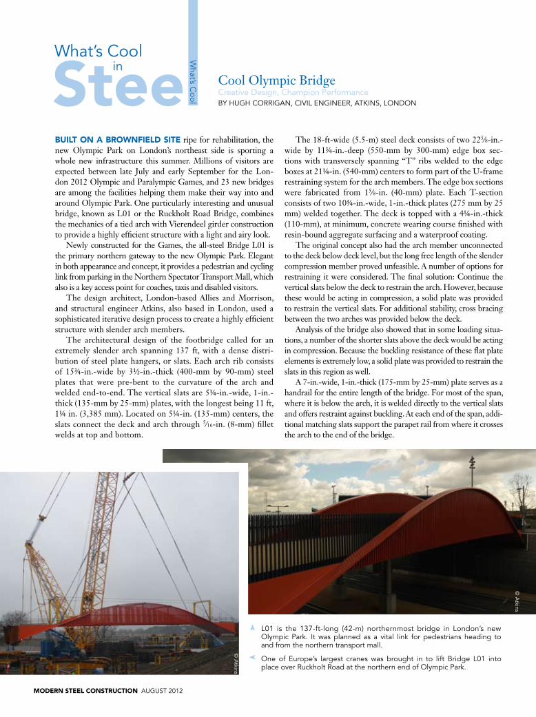
BUILT ON a BROwNFIELD SITE ripe for rehabilitation, the new Olympic Park on London’s northeast side is sporting a whole new infrastructure this summer. Millions of visitors are expected between late July and early September for the Lon-don 2012 Olympic and Paralympic Games, and 23 new bridges are among the facilities helping them make their way into and around Olympic Park. One particularly interesting and unusual bridge, known as L01 or the Ruckholt Road Bridge, combines the mechanics of a tied arch with Vierendeel girder construction to provide a highly efficient structure with a light and airy look.
Newly constructed for the Games, the all-steel Bridge L01 is the primary northern gateway to the new Olympic Park. Elegant in both appearance and concept, it provides a pedestrian and cycling link from parking in the Northern Spectator Transport Mall, which also is a key access point for coaches, taxis and disabled visitors.
The design architect, London-based Allies and Morrison, and structural engineer Atkins, also based in London, used a sophisticated iterative design process to create a highly efficient structure with slender arch members.
The architectural design of the footbridge called for an extremely slender arch spanning 137 ft, with a dense distri-bution of steel plate hangers, or slats. Each arch rib consists of 15¾-in.-wide by 3½-in.-thick (400-mm by 90-mm) steel plates that were pre-bent to the curvature of the arch and welded end-to-end. The vertical slats are 5¼-in.-wide, 1-in.-thick (135-mm by 25-mm) plates, with the longest being 11 ft, 1¼ in. (3,385 mm). Located on 5¼-in. (135-mm) centers, the slats connect the deck and arch through 5∕16-in. (8-mm) fillet welds at top and bottom.
The 18-ft-wide (5.5-m) steel deck consists of two 225∕8-in.-wide by 11¾-in.-deep (550-mm by 300-mm) edge box sec-tions with transversely spanning “T” ribs welded to the edge boxes at 21¼-in. (540-mm) centers to form part of the U-frame restraining system for the arch members. The edge box sections were fabricated from 15∕8-in. (40-mm) plate. Each T-section consists of two 10¾-in.-wide, 1-in.-thick plates (275 mm by 25 mm) welded together. The deck is topped with a 4¼-in.-thick (110-mm), at minimum, concrete wearing course finished with resin-bound aggregate surfacing and a waterproof coating.
The original concept also had the arch member unconnected to the deck below deck level, but the long free length of the slender compression member proved unfeasible. A number of options for restraining it were considered. The final solution: Continue the vertical slats below the deck to restrain the arch. However, because these would be acting in compression, a solid plate was provided to restrain the vertical slats. For additional stability, cross bracing between the two arches was provided below the deck.
Analysis of the bridge also showed that in some loading situa-tions, a number of the shorter slats above the deck would be acting in compression. Because the buckling resistance of these flat plate elements is extremely low, a solid plate was provided to restrain the slats in this region as well.
A 7-in.-wide, 1-in.-thick (175-mm by 25-mm) plate serves as a handrail for the entire length of the bridge. For most of the span, where it is below the arch, it is welded directly to the vertical slats and offers restraint against buckling. At each end of the span, addi-tional matching slats support the parapet rail from where it crosses the arch to the end of the bridge.
Cool Olympic BridgeCreative Design, Champion PerformanceBy hugh COrrIgan, CIvIL EngInEEr, atKIns, LOnDOn
What’s C
ool
What’s Coolin
L01 is the 137-ft-long (42-m) northernmost bridge in London’s new Olympic Park. It was planned as a vital link for pedestrians heading to and from the northern transport mall.
One of Europe’s largest cranes was brought in to lift Bridge L01 into place over ruckholt road at the northern end of Olympic Park.
➤
➤
© a
tkins
© a
tkins

august 2012 MODERN STEEL CONSTRUCTION
The deck itself is integrally connected to the foundations, which comprise reinforced concrete abutment walls on piles. In constructing the bridge, it was set on temporary support towers prior to placement of the top concrete section. That allowed the ends of the edge beams to be anchored into the concrete abutment via thrust plates and shear connectors.
From Box to BowThe bridge design began as a basic box girder structure and
ultimately morphed into a beautiful bowstring arch bridge. Although it was designed to current British Standards Institu-tion standards, these provided little guidance on how to account for buckling arched structures.
To validate and optimize the design, engineers modeled the bridge using elastic critical buckling analysis to determine member slenderness, as well as the structure’s global buckling modes and susceptibility. The lateral restraint provided by the steel deck plate was not included in the structural model, but the section of handrail welded to the vertical slats was included.
Careful consideration was required in modeling the founda-tions, as the bridge is integral with them, and the fixity to the foundations and foundation stiffness had a significant impact on the structural behavior. The abutment walls were modeled using a grillage of beam members, and forces from the soil pres-sure were applied to the structural model as an applied load. The pile foundations were modeled using spring elements with an appropriate stiffness.
Global BucklingThe arch ribs are necessarily very slender and rely heavily
on the vertical slats for their stability, so one of the key issues in the design was accurately assessing global buckling effects. The structure was susceptible to two main modes of global buckling: in-plane and out-of-plane. The critical mode varied, depend-ing on the exact dimensions chosen for the main structural components, the foundation design parameters and the load-ing applied. The critical mode of buckling changed throughout
the design iteration process as dimensions of different elements were varied and the arch profile was finalized.
In its final form, the bridge’s in-plane buckling mode involved the arch and deck and was critical for temperature loading on the structure. The out-of-plane mode involved only the arch and was critical for pedestrian loading effects.
The out-of-plane buckling of the arch is resisted by the slats through U-frame restraint. The resistance to in-plane buckling provided by the vertical slats is higher than might be expected for such a slender arch profile. Although each individual slat provides little stiffness, by acting together at 5¼-in. (135 mm) spacing they provide significant restraint to the arch through the moment con-nections at each end and force the deck and arch to act together.
Construction of Bridge L01 began in May of 2010 and was completed this past March. The 137-ft-long, 18-ft-wide steel structure was fabricated in Wales. Shipped in several pieces, it was welded together on-site prior to being lifted into place. One of Europe’s largest cranes was brought in for the lift, which occurred in November 2010.
the parapet rail on Bridge L01 is welded to each of the vertical slats, beyond which can be seen the adjacent temporary bridge erected to provide increased capacity during the games.
© a
tkins
viewed from this angle, the vertical slats connecting the arches with the deck appear to be a solid wall.
➤
➤
➤
© a
tkins
© a
tkin
s

MODERN STEEL CONSTRUCTION august 2012
GOEThE’S METaphOR of architecture as “frozen music” emphasizes the tight relationship between architecture and music in performance spaces.
And it is beautifully illustrated by the Sun Valley Pavilion, a grand perfor-mance chamber in which the structure becomes a musical instrument itself.
The Pavilion is located on the southwestern end of the central campus at the Sun Valley Resort in Idaho, considered one of America’s preeminent ski resorts. When we were invited to design our latest music pavilion at Sun Valley, we understood that the Sun Valley Summer Symphony and the Sun Valley Resort wanted a structure that combined the seasonal and ephemeral quality of a summer tent that they had previously rented, with a more permanent facility that could accommodate the theatrical and acous-tic requirements for the orchestra. In short, they wanted an outdoor feel-ing in a state-of-the-art performance facility.
Of course, being at a ski resort means lots of snow. Having designed per-manent and seasonal outdoor performing arts facilities for thirty years, we immediately realized that the local snow load requirements would not allow for a permanent tent-like fabric structure and that the facility was too big for a smaller seasonal roof that needed to be dismantled each winter. What to do?
Inspired by the grand natural setting of valleys and mountains, we started with the terrain and used two stone retaining walls rising to an apex, creating a stage area that combines an intimate sense of place and melding with the landscape. The sky and mountains are captured by a free-flowing roof, com-prised of two parts: a seasonal luminous tensile membrane covering 1,500 seats and a permanent steel cable net with wood cladding and a copper roof-ing, which provides cover over the stage and support facilities.
In the past, we had used fabric cable nets when we needed to take snow loads, but 100 lb. per sq. ft, with drifting of up to 200 lb. in some areas, is a pretty tall order. Working with the architect, Ruscitto Latham Blanton, we started thinking of alternative materials. If we replaced the fabric with a steel cable net and used wood to take on the high vertical loads, we felt we had a chance. Using a series of three-cord 10-in.-diameter steel pipe trusses with varying wall thicknesses, we created both the 70-ft-high proscenium arch and
Cool Concert Venuemusic in the mountainsBy nIChOLas gOLDsmIth, FaIa, sEnIOr PrInCIPaL, FtL DEsIgn EngInEErIng stuDIO, nEW yOrK
What’s C
ool
What’s Coolin
the steel cable net being attached to the steel framing trusses below.
Pfeiffer cast connections with galfan full-locked cable, including adjustable clevises.
➤
Opening-day performance of the sun valley symphony in the Pavilion. ➤
➤
Courtesy of rLB architects
Courtesy of rLB architects
Courtesy of sun valley resort

the backstage framing (fabricated by AISC Member/AISC Certified Fabricator Jesse Engineering, Tacoma, Wash.) to contain the boundary of the cable net. The trusses had angles welded to them to accept the roof cladding, which was applied later after the tursses were installed. We were then able to place sleepers on a series of metal “shoes” attached to the cable net nodes. The shoes consisted of galvanized formed plates on an upstand, which were mounted to the cable net's machined steel nodes. Above these sleepers, a shiplap Douglas Fir cladding is supported and patterned on the diagonal so as to remain in straight lines and not require special forming.
The cable net consisted of 1-in.-diameter Galfan locking stand cables within a 2-ft by 4-ft spacing (2 ft for the downward pressures and 4 ft for the uplift). At each intersection was a four-section wire rope clamp that attached the cables to the metal shoes and wood sleepers. In total the cable net consisted of 82 individual cables.
When it came to acoustics, the wood acted much like the inside of a violin, giving resonance and brightness to the space. To enhance this effect, we worked with acous-tician Jaffe Holden and theater consultants Auerbach Pollock & Friedlander to develop the final seating layout and an overhead light-ing grid, which was integrated into a hanging
wooden acoustic shell. This shell consisted of lightweight steel trusses framed with adjust-able wooden panels that can be tuned for different acoustical applications. Sporting a highly engineered amplification system, sound emanates from the stage, passing seam-lessly through great spans of techno-textile membrane to the outer lawn, which hosts an additional seating area for 2,000.
For the audience area, we designed a soft tensile membrane roof of PVC polyester, which is installed each year in the spring and removed in the fall; this gives the facility the sense of an outdoor room. The membrane roof was designed as a tensile structure and an extension of the cable net using undulat-ing folded radial-wave geometry. The fabric membrane uses steel cable edges and steel membrane plates, which collect both the tensile and slip loads of the membrane and transfer them to the supporting steelwork below. Below the fabric itself is a hanger cable, which applies the final prestress to the membrane resisting the upward wind pres-sures. The tensile roof is designed to require no support structures, giving all of the 1,500 seats an unobstructed view of the stage.
By using the steel cable net and the ten-sioned membrane as two interdependent elements, the entire roof structure works together as a new milestone in the develop-ment of a tensile architecture.
view of shiplap fir attached to wooden sleeper and steel truss, with steel cable net below.
view from the lawn of the Pavilion at night.
➤
➤
august 2012 MODERN STEEL CONSTRUCTION
Interior view of the performance stage and overhead acoustic shell.
Fabrication of steel trusses with jig at Jesse Engineering in tacoma, Wash.
➤
➤
Courtesy of rLB architects
Courtesy of sun valley resort
Courtesy of sun valley resort
Courtesy of Jesse Engineering

MODERN STEEL CONSTRUCTION august 2012
Cool Sculpturea Classic, reinventedBy C.J. rILEy, P.E., Ph.D., assIstant PrOFEssOr, anD sEan st.CLaIr, Ph.D., P.E., assOCIatE PrOFEssOr, DEPartmEnt OF CIvIL EngInEErIng, OrEgOn InstItutE OF tEChnOLOgy, KLamath FaLLs, OrE.
What’s C
ool
What’s Coolin
LaST OCTOBER, AISC's Steel Sculpture turned 25. Since its beginnings in 1986 this teaching sculpture has been installed, in varying forms, at more than 130 locations around the world (see MSC 10/2011, p. 20). The original purpose of the sculpture (above, inset), as designed by Duane Ellifritt, was to help engineering stu-dents better understand structural steel by exemplifying the many methods of steel framing and their corresponding connections.
For more than five years, the Civil Engineering Depart-ment faculty at Oregon Institute of Technology wanted to add one of these sculptures to the school’s campus in Klamath Falls. Knowing that their students could benefit greatly by seeing and touching—and in some cases deconstructing and constructing—various connections, the faculty sought funding sources to build the sculpture and began collecting components.
While some small commitments and in-kind donations were made over the course of a few years, the windfall support to com-plete the project came from a very timely source. Owens Hall, the building that houses the Civil Engineering Department, was due for deferred maintenance in the form of asbestos abatement and seismic retrofits at the same time that federal stimulus funds became avail-able. As this resulted in a much larger capital project, it triggered Oregon’s Percent for Art program, which required that 1% of the project’s budget be spent on public art in or around the building.
The program required a rigorous process coordinated by a representative of the Oregon Arts Commission—and involving a committee of architects, educators, students and artists—that led to the eventual selection of a local artist. Lee Imonen, a sculptor
and art teacher at Lane Community College in Eugene, Ore., was chosen for his experience with large, construction-style art that focuses on its place in the community and the environment.
Imonen’s vision for the sculpture resulted in a final design that would serve two purposes. The first was to follow Ellifritt’s original idea of teaching structural steel connections; the sculpture incorpo-rates 24 different types of steel connections. As the connections in the sculpture actually carry load, shear connections, moment con-nections and splices are placed where they are most appropriate and where analysis can also consider the load side of the equation. With the breadth of connection types from the original Ellifritt sculpture now provided in a format that requires structural analysis, this new version of sculpture is an valuable tool for improving the instruction of steel design for hundreds of civil engineering students at Oregon Tech. It can also be used as a basis for analysis and design prob-lems in courses other than steel design, such as statics, engineering mechanics, structural analysis and even concrete foundation design.
The sculpture’s second purpose is to serve as a place-based, artis-tic metaphor for the Klamath River basin, and virtually every ele-ment represents something. For starters, the sculpture includes a suspended basin that is roughly the same shape as the Klamath basin. This suspended form is covered in a patchwork of aluminum plates representing the rural community’s patchwork of farms and land and the heavily engineered nature of the Klamath River watershed. The basin has a fracture in it, symbolic of the sometimes combative and opposing nature of the people and politics of the Klamath Basin, as well as the volcanic history of the area that formed the shape of
Photos, except above inset: Courtesy of Oregon tech

august 2012 MODERN STEEL CONSTRUCTION
the surrounding earth. As with the river basin, the metal basin serves to collect and distribute water downward (or down-stream). Water, and who owns the rights to it, has long been a contentious issue in the Klamath basin. Historically, conflicts over water have taken place between native tribes, farmers and ranchers and environmentalists who wish to protect the wildlife that depend upon the water. These three influences are rep-resented by the three HP14x89 structural steel columns and W8x35 and W6x12 cantilevered beams that hold the basin and its water aloft and in tension via ½-in. galvanized steel cables. Each column pulls the water in its own direction, and yet each is necessary to keep the water from being lost altogether. In terms of equilibrium, the columns both support the basin and depend upon it for stability. In fact, dead load moments at the base of each column are zero as a result of Imonen’s choice of 7.5° for the slope of the columns, based on aesthetic considerations, a serendipitous detail confirmed by the authors during design. Numerous other historical representations, such as wagon wheels and logging derricks, can be found in the sculpture, honoring the region’s past while looking toward the future.
Ultimately, the entire structure is a metaphor for the delicate balance of the area’s natural resources. It provides an opportunity to teach not only technical topics, but also important concepts regarding sustainability and the envi-ronment. Steel, in this form, is not merely a structural material with connections to be comprehended, but also a piece of the complex ongoing experiment of society.
While the erection of the sculpture was relatively simple, it involved a number of different groups. The main structural members were lengths of HP14x89 donated by Hamilton Construction of Springfield, Ore. (an AISC Member Fabrica-tor). Imonen split and re-welded them to give them the tapered look and provide another opportunity to discuss the challenge of connecting steel to steel. Precision Structural Engineers, in Klamath Falls, donated time to review and seal the construc-tion drawings. The university’s facilities department and the faculty members involved donated time for design, permit-ting and inspection. Students participated in the base-plate and foundation design and drafting, and local ready-mix companies offered to pump and place the foundation concrete at cost. The collaboration between students, professors, engineers, contrac-tors and artists is what made this project such a success.
BASIN: A Steel Connections Teaching Sculpture (the sculpture’s formal title) was installed on the Oregon Tech campus in the summer of 2011. While it has a very dif-ferent look and style than the original Ellifritt sculpture, it still serves the purpose of helping students to visualize complex steel connections—with the additional benefit of helping them think beyond the technical and consider more than just engineering, economy and efficiency; it encourages them to consider the social and environmental impacts of their designs as well.
BasIn: a steel Connections teaching sculpture. Inset: the aIsC steel sculpture.
Top: a sketch of the sculpture. Middle: Lee Imonen, the sculpture's creator.➤
➤
the sculpture's dedication at Oregon tech.➤

MODERN STEEL CONSTRUCTION august 2012
Cool FurnitureWeighty WelcomeBy sImEOn BrunEr, PrInCIPaL, BrunEr/COtt & assOCIatEs, CamBrIDgE, mass.
What’s C
ool
What’s Coolin
FEw DESkS wEIGh two tons.But the front desk at Cambridge,
Mass.-based architecture firm Bruner/Cott & Associates does.
The desk, which is made of struc-tural steel, is the second of several pieces of furniture that sculptor Mike Green
designed and built for the firm. Inspira-tion came from B/CA’s work in reinvent-ing historic mill buildings and showcas-ing their industrial heritage.
“I wanted the desk to pay homage to this and to the variety of textures and forms common to construction sites
across the country,” says Green. Efforts were made to minimize weight, doubling edges and using thinner sheet where pos-sible, without sacrificing the visual impact of the structural steel. Nevertheless, struc-tural reinforcements were required for the building to safely support the two-ton desk, which is just over 4 ft tall and has a 9-ft x 10-ft workstation footprint.
The steel is a combination of new steel and scrap steel, both wide-flange and sheet, left over from the construction of the firm’s new office. The desk uses both welded and riveted connections; some of the ¾-in. riv-ets camouflage hidden bolt connections (using bolts allowed the individual pieces to fit in the elevator so that the desk could be assembled in the office). The desktop is Southern Longleaf Pine reclaimed from the Massachusetts Museum of Contempo-rary Art, which is housed in a former fac-tory building in North Adams. The top of the outer section is granite.
Other pieces by Mike Green can be seen on his website: www.mikegreensculpture.com.
Photos: mike green
august 2012 MODERN STEEL CONSTRUCTION
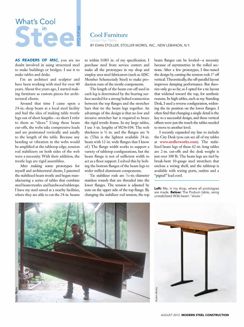
aS REaDERS OF MSC, you are no doubt involved in using structural steel to make buildings or bridges. I use it to make tables and desks.
I'm an architect and sculptor and have been working with steel for over 40 years. About five years ago, I started mak-ing furniture as custom pieces for archi-tectural clients.
Around that time I came upon a 24-in.-deep beam at a local steel facility and had the idea of making table trestle legs out of short lengths—so short I refer to them as “slices.” Using these beam cut-offs, the webs take compressive loads and are positioned vertically and axially to the length of the table. Because any bending or vibration in the webs would be amplified at the tabletop edge, tension rod stabilizers on both sides of the web were a necessity. With their addition, the trestle legs are rigid assemblies.
After making some prototypes for myself and architectural clients, I patented the stabilized beam trestle and began man-ufacturing a series of tables that combine steel beam trestles and hardwood tabletops. I have my steel sawed at a nearby facilities, where they are able to cut the 24-in. beams
to within 0.003 in. of my specification. I purchase steel from service centers and make all the prototypes in my shop and employ area steel fabricators (such as AISC Member Schenectady Steel) to make pro-duction runs of the trestle components.
The length of the beam cut-off used in each leg is determined by the bearing sur-face needed for a strong bolted connection between the top flanges and the stretcher bars that tie the beam legs together. An advantage of the design is that no low and invasive stretcher bar is required to brace the rigid trestle frame. In my large tables, I use 3-in. lengths of W24×104. The web thickness is ½ in. and the flanges are ¾ in. (This is the lightest available 24-in. beam with 12-in. wide flanges that I know of.) The flange width works to support a variety of tabletop configurations, but the beam flange is not of sufficient width to act as a floor support. I solved this by bolt-ing the bottom flanges of the beam legs to wider milled aluminum components.
Tie stabilizer rods are 7∕16-in.-diameter stainless rounds that are threaded into the lower flanges. The tension is adjusted by nuts on the upper side of the top flange. By changing the stabilizer rod tension, the top
beam flanges can be leveled—a necessity because of asymmetries in the rolled sec-tions. After a few prototypes, I fine-tuned the design by canting the tension rods 1° off vertical. Theoretically, the off-parallel layout improves damping performance. But theo-ries only go so far, so I opted for a tie layout that widened toward the top, for aesthetic reasons. In high tables, such as my Standing Desk, I used a reverse configuration, widen-ing the tie position on the lower flanges. I often find that changing a single detail is the key to a successful design, and these vertical offsets were just the touch the tables needed to move to another level.
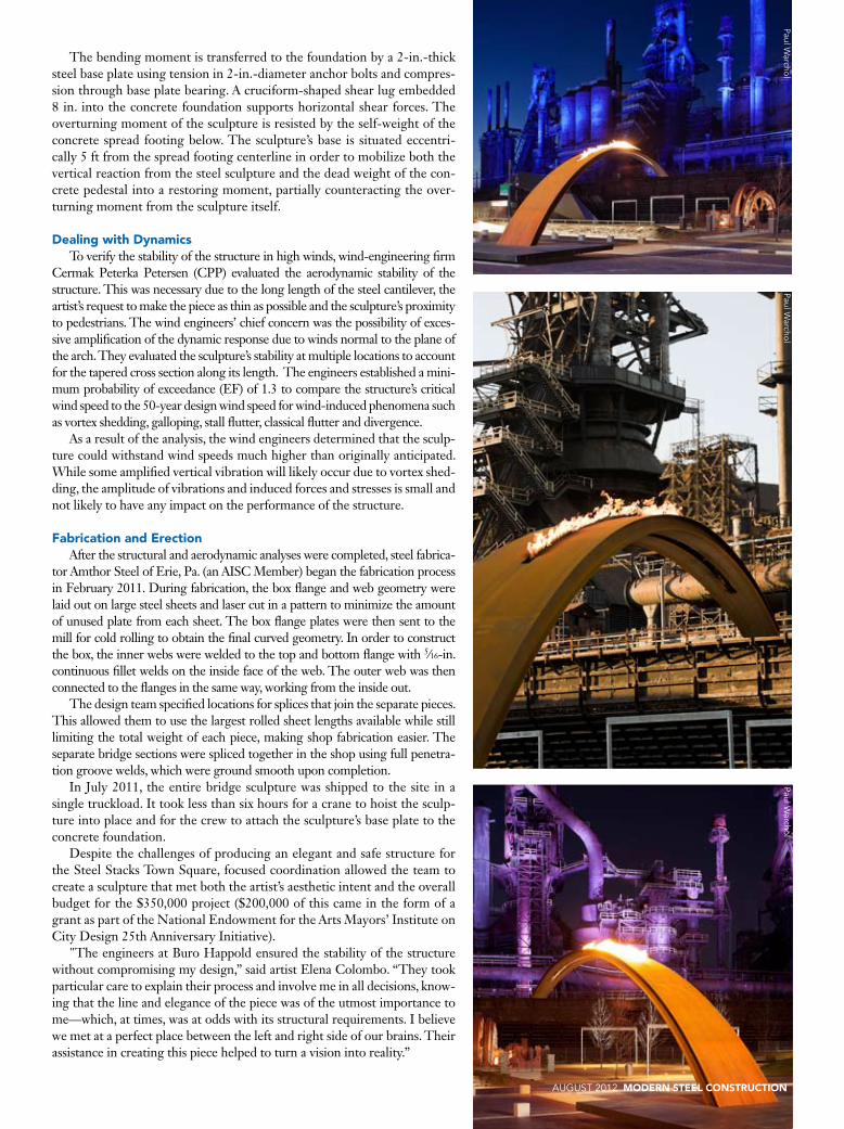
I recently expanded my line to include the City Desk (you can see all of my tables at www.stollerworks.com). The stabi-lized beam legs of these 62-in.-long tables are 2-in. cut-offs and the desk weight is just over 100 lb. The beam legs are tied by break-bent 10-gauge steel stretchers that enclose a wiring shelf, and the tabletop is available with wiring ports, outlets and a “pigtail” lead cord.
Cool Furnitureunder the tableBy Evan stOLLEr, stOLLEr WOrKs, InC., nEW LEBanOn, n.y.
What’s C
ool
What’s Coolin
Left: me, in my shop, where all prototypes are made. Below: the Podium table, using unstabilized W36 beam "slices."
stol
ler
Wor
ks
stol
ler
Wor
ks

MODERN STEEL CONSTRUCTION august 2012
Cool CenterpieceBridge on FireBy JEFFrEy thOmPsOn, P.E., assOCIatE struCturaL EngInEEr, BurO haPPOLD, nEW yOrK
What’s C
ool
What’s Coolin
STEEL STaCkS is transforming the largest privately owned brownfield site in the United States into an arts destination.
This new cultural and entertainment campus, at the site of the former Bethlehem Steel plant, includes the 65,000-sq.-ft ArtsQuest Center, which hosts live concerts and independent films year round, as well as the City of Bethlehem's Visitor Center and a new outdoor music pavilion. At the center of it all is a new sculpture that reflects the site’s industrial history.
Artist Elena Colombo of Colombo Construction Corp., located in Brooklyn, N.Y., designed the new centerpiece. The sculpture, called The Bridge, is an arching structure reminis-cent of the steel bridges whose materials had been created at the Bethlehem plant when it was still active. The design is relatively simple: a 70-ft-long, 25-ft-tall curved steel plate (weighing 9 tons) that is tapered from 8 ft wide at the base to 3 ft wide at the tip. A gas line supplies a blue flame along the upper portion of the piece and recalls the flames of the former steel factory. The sculpture curves above a newly constructed sidewalk and roadway, with its tip pointing toward the new outdoor music pavilion and existing steel stacks. The piece spans not only the sidewalk, but also spans time, linking the history of Bethlehem Steel to the present and future of ArtsQuest.
DevelopmentStructural engineers from the New York office of interna-
tional engineering firm Buro Happold performed preliminary calculations for strength and serviceability, taking into account the scale of the proposed sculpture. Since the structure is out-doors and exposed to winds, the dynamic performance and overall safety of the sculpture became a concern. The engineers
realized that the artist’s design for a curved steel plate would need reinforcement to meet the necessary strength and service-ability requirements. This was especially important because the gas line extends along the underside of the steel to ignite burn-ers situated on the topside, which provide the 1-ft-high flame along the length of the sculpture.
To stabilize the sculpture, the engineers constructed the steel form using two parallel, arched and tapered box sections, sharing a top and bottom flange near the base. The sections are tied together by three vertical shear plates between inner box webs along the length of the piece. The overall box dimensions at the base are 92 in. wide × 22 in. deep and taper as they rise, reaching 33 in. wide × 8 in. deep at the tip. Because the structure is exposed to the elements, the engineers used ASTM A588 weathering steel.
The steel box sections are welded to a 2-in.-thick base plate that weighs nearly 1.5 tons. The base plate is anchored to the concrete foundation via 18 2-in.-diameter F1554 anchor bolts. The primary concrete spread footing foundation is 16 ft wide by 21 ft long by 4 ft deep and is buried 1 ft below grade. A 24-ft by 24-ft by 8-in.-thick cantilever cast-in-place concrete slab creates an elevated pedestrian viewing platform above the foundation.
Buro Happold performed a finite element analysis following the initial design in order to determine deflections and moments. The steel box structure acts as a cantilever beam that transfers the vertical load to the foundation through bending and shear stress. The engineers determined the depth of the steel box by limiting the amount of deflection at the tip to 8 in. under dead loads and snow loads. They then optimized the box plate sizes to provide the required bending capacity while respecting the local buckling requirements for a slender flange under compression.
Paul Warchol
The bending moment is transferred to the foundation by a 2-in.-thick steel base plate using tension in 2-in.-diameter anchor bolts and compres-sion through base plate bearing. A cruciform-shaped shear lug embedded 8 in. into the concrete foundation supports horizontal shear forces. The overturning moment of the sculpture is resisted by the self-weight of the concrete spread footing below. The sculpture’s base is situated eccentri-cally 5 ft from the spread footing centerline in order to mobilize both the vertical reaction from the steel sculpture and the dead weight of the con-crete pedestal into a restoring moment, partially counteracting the over-turning moment from the sculpture itself.
Dealing with DynamicsTo verify the stability of the structure in high winds, wind-engineering firm
Cermak Peterka Petersen (CPP) evaluated the aerodynamic stability of the structure. This was necessary due to the long length of the steel cantilever, the artist’s request to make the piece as thin as possible and the sculpture’s proximity to pedestrians. The wind engineers’ chief concern was the possibility of exces-sive amplification of the dynamic response due to winds normal to the plane of the arch. They evaluated the sculpture’s stability at multiple locations to account for the tapered cross section along its length. The engineers established a mini-mum probability of exceedance (EF) of 1.3 to compare the structure’s critical wind speed to the 50-year design wind speed for wind-induced phenomena such as vortex shedding, galloping, stall flutter, classical flutter and divergence.
As a result of the analysis, the wind engineers determined that the sculp-ture could withstand wind speeds much higher than originally anticipated. While some amplified vertical vibration will likely occur due to vortex shed-ding, the amplitude of vibrations and induced forces and stresses is small and not likely to have any impact on the performance of the structure.
Fabrication and ErectionAfter the structural and aerodynamic analyses were completed, steel fabrica-
tor Amthor Steel of Erie, Pa. (an AISC Member) began the fabrication process in February 2011. During fabrication, the box flange and web geometry were laid out on large steel sheets and laser cut in a pattern to minimize the amount of unused plate from each sheet. The box flange plates were then sent to the mill for cold rolling to obtain the final curved geometry. In order to construct the box, the inner webs were welded to the top and bottom flange with 5∕16-in. continuous fillet welds on the inside face of the web. The outer web was then connected to the flanges in the same way, working from the inside out.
The design team specified locations for splices that join the separate pieces. This allowed them to use the largest rolled sheet lengths available while still limiting the total weight of each piece, making shop fabrication easier. The separate bridge sections were spliced together in the shop using full penetra-tion groove welds, which were ground smooth upon completion.
In July 2011, the entire bridge sculpture was shipped to the site in a single truckload. It took less than six hours for a crane to hoist the sculp-ture into place and for the crew to attach the sculpture’s base plate to the concrete foundation.
Despite the challenges of producing an elegant and safe structure for the Steel Stacks Town Square, focused coordination allowed the team to create a sculpture that met both the artist’s aesthetic intent and the overall budget for the $350,000 project ($200,000 of this came in the form of a grant as part of the National Endowment for the Arts Mayors’ Institute on City Design 25th Anniversary Initiative).
"The engineers at Buro Happold ensured the stability of the structure without compromising my design,” said artist Elena Colombo. “They took particular care to explain their process and involve me in all decisions, know-ing that the line and elegance of the piece was of the utmost importance to me—which, at times, was at odds with its structural requirements. I believe we met at a perfect place between the left and right side of our brains. Their assistance in creating this piece helped to turn a vision into reality.”
august 2012 MODERN STEEL CONSTRUCTION
Paul Warchol
Paul Warchol
Paul Warchol

Cool TowerCapital LeanBy PEyman a. nEJaD, P.E., Ph.D., DIrECtOr OF struCturaL EngInEErIng, gLOBaL COnsuLtIng EngInEErIng PraCtICE, tJEg IntErnatIOnaL, DuBaI, anD JEFF sChOFIELD, aIa, assOCIatE, rmJm DuBaI
What’s C
ool
What’s Coolin
IF yOU’RE GOING TO BUILD a signature tower for an arts and exhibition center, you might as well shoot for the record books.
Capital Gate, completed last year in Abu Dhabi, United Arab Emirates, is the focal point of the Abu Dhabi National Exhibitions Company’s (ADNEC) exhibition halls and Capi-tal Centre—and with an 18° westward lean, holds the current Guinness World Record for “world’s furthest leaning man-made tower.” It is also the only building in the world that features two diagrid systems: an external diagrid defining the tower’s shape and an internal diagrid defining an atrium in the upper half of the tower.
Growing and DistortingThe 34-story, 160-m (525-ft) tower is a mixture of offices,
five-star hotel suites and retail shopping. A 4-m (13.1-ft) floor-to-floor height is maintained throughout the tower, with a few exceptions, resulting in a consistent vertical arrangement of the external structural diagrid.
As the tower rises, it grows and distorts toward the west. The external diagrid is achieved with cross-braced frames that extend two stories each for the full height of the tower. It provides lateral stability (~30%) and acts as the perimeter load-bearing element for the floor structures. The main lateral stability element (~70%) is the central oval concrete core that extends vertically for the full height of the tower. Between the core and the external diagrid, two rows of steel columns rise up to the mid-tower levels, and steel beams span between the external diagrid and the concrete core, supporting composite metal deck and concrete floor slabs. Since the floors follow the diagrid as it shifts from its longitudinal axis, the outer row of columns stops at the 13th floor and the inner row stops at the 17th floor.
The internal diagrid goes from the 18th floor to the roof to form the atrium for the hotel floors and is also attached to the core. Steel beams span directly between the external and internal diagrids, creating column-free floor spaces, with typi-cal spans about 12 m (39 ft) in length.
The building uses 13,000 metric tons (14,330 U.S. tons) of structural steel in all. The framing system consists of 702 external diagrid nodes (intersection of the members)—with the addition of 5 nodes of external dummy diagrids (for visual effect only) at the 18th and 19th floors—and 120 internal diagrid nodes. At these intersect-ing points, the HSS members meet with offsets in two axes, and floor beams meet at the third axis along their surfaces. As none of
a cross-section of the tower, showing the internal and external diagrids and the ovular concrete core (above). a view from the interior (below).
MODERN STEEL CONSTRUCTION august 2012
➤
Courtesy of rmJm
Cou
rtes
y of
tJE
g a
nd r
mJm
➤
➤

the panels are coplanar to one another, each node is unique and formed with heavy, thick cruciform punched through the plates. In order to minimize the member offsets at the nodal points, diagrid members have been oriented by the “bisection of bisecting planes” method (i.e., the division of diagrids into two equal or congruent parts, usually by a line, which is then called a bisector).
The external diagrid is composed of square hollow structural sections (HSS) 600 × 600 mm (23.6 in. × 23.6 in.). Each diagrid member is a different length depending on the angle at which it leans. The external diagrid members are made from welded steel plates, 80 mm (3.15 in.) thick at the bottom floors, and progres-sively thinning out to 40 mm (1.57 in.) at the top floors. Square sections were chosen over circular sections to provide a flat surface for the façade glazing mullions to attach and to keep the internal and external diagrids in the same line. The connection node details consist of crucifix plates welded to the intersecting cross-bracing members and bolted to the external tie beam. Each node point includes two frame members that extend from floor to floor, cre-ating an “A” shaped piece that was fabricated off-site and erected into position and welded (or bolted) on-site to the other installed node assemblies. Each node has different end angles due to varying geometries and dead load deflections of the structure.
The internal diagrid around the atrium is made of round HSS (400 mm [15.75 in.] in diameter and ranging in thickness from 16 mm to 32 mm [0.63 in. to 1.26 in.]) and is supported on deep concrete beams that project from the central concrete core on floors 17 and 18. While square HSS was used for the external diagrid for practical purposes, aesthetics drove the selection of round HSS for the internal diagrid. The internal node connec-tion details are similar to those of the external diagrid.
the internal diagrid of the atrium.
the tower leans westward at 18°.
the 34-story tower is the focal point of the largest exhibition center in the Persian gulf region.
➤
➤
➤
august 2012 MODERN STEEL CONSTRUCTION
Photos this page: Courtesy of tJEg and rmJm

MODERN STEEL CONSTRUCTION august 2012
Cool BIM RenovationBIm’s Benefits Proven in ProvidenceBy DavID J. ODEh, P.E., vICE PrEsIDEnt anD PrInCIPaL, ODEh EngInEErs, InC.
What’s C
ool
What’s Coolin
whILE MaNy DESIGN FIRMS are beginning to test the waters of building infor-mation modeling and others are still staring at it appre-hensively, some have jumped right in.
Odeh Engineers, a full-service structural engi-neering consulting firm in North Providence, R.I., is in the latter group; since 2006, the company has used BIM technology for nearly all of its work.
One of the firm’s latest BIM projects is Brown University's Warren Alpert Medical School, completed in 2011 and located in the heart of the school’s new campus in the historic Jewelry District of Providence, R.I. The project involved converting the original four-story, 1920s-era, cast-in-place concrete industrial building (which was 137,000 sq. ft) into a state-of-the art, LEED Gold (pending) medical education building. The final project features two 150-seat (column-free) lecture halls, large classrooms, anatomy labs and a new multi-story, glass-enclosed atrium; it used 300 tons of structural steel.
The key structural issue the project presented was the need to create open, airy spaces within a building that had closely-spaced columns (19 ft on center in each direction) and low floor-to-floor heights. The success of the renovation was dependent on the ability to cost-effectively remove twelve large concrete columns (with drop capitals) at the ground level to support the new program, without diminishing the structure’s lateral and gravity load carrying capac-ity. Odeh, with its design-build team partners Ellenzweig Architects of Cambridge, Mass. and general contractor Suffolk Construction of Boston, used Autodesk Revit and Navisworks to meet this design goal, as these tools allowed them to explore multiple design options by displaying all aspects of the structure and illustrating the struc-tural issues. This in-depth modeling lead to a design that reduced the demolition requirements as well as overall project cost.
In schematic design, Odeh created a 3D model of the existing structure, then evaluated three options for structural modifications. The first two options called for new steel beams and columns to sup-port the existing structure, which was to remain, and/or new com-posite deck slabs on metal deck. However, this would have required extensive demolition and costly temporary shoring. In addition, the transfer girders would have been very deep and resulted in unac-ceptably low ceiling heights in the auditorium spaces.
So, Odeh developed and modeled a third option that involved building new full-story-deep steel transfer trusses within the exist-ing second floor space. Combined with the idea of “pre-loading” the trusses by jacking them against the dead load of the upper floors of the building, Odeh demonstrated that this option could achieve the desired open space and ceiling heights for classrooms—with far less demolition and almost no shoring. Leveraging the data in BIM, the team quantified the cost and schedule benefits of this approach and created 3D animations and renderings to illustrate the feasibil-ity of the design to the client.
The truss system uses W14 chords and HSS web members that were small enough to thread through the existing building win-dow openings and connect together with field-welded through plate connections. The new trusses bear on new W14 columns that extend down through the existing floors to new mat foundations. Once the completed trusses were in place, they were connected to the tops of the existing concrete columns to be removed. Hydraulic jacks were used to pre-deflect the trusses downward, thus transfer-ring the load of each column to the truss. With the trusses carrying the load of the upper floors, the ground-floor columns could be safely removed without any further deflection of the upper floors.
The truss design yielded a 25% savings in weight when com-pared to the other design options considered. The owner also real-ized substantial savings in cost and schedule due to the elimina-tion of the shoring required for the other options. The final cost was $28.8 million, not including optional owner-directed changes, compared to a budget of $29.6 million, and the project was com-pleted in 18 months, on schedule.
Warren Jag
gers
view of the new atrium and grand stair structures created by enclos-ing the courtyard of the building.
the Warren alpert medical school project involved trans-forming 1920s industrial space into a modern medical education facility.
➤➤
One of Odeh’s 3D models of the medical school, created in autodesk revit and showing new steel trusses.
➤
Od
eh Engineers
Od
eh Engineers

august 2012 MODERN STEEL CONSTRUCTION
CaSTaLIa SRL, MILaN, ITaLy, has been developing struc-tural steel-related software since 1991. In 2008, the company released CSE (Connection Study Environment), a program that designs and checks steel connections, and is now preparing to distribute it outside of Italy for the first time.
CSE is able to study, design and check connections created by freely placing components. This means that the program is not using specific, preprogrammed connections, but rather uses a general model that is able to manage virtually every possible connection scenario.
Starting from a standard finite element model, which can be imported or built inside the program, CSE recognizes equal connections and lets the user construct whatever connections they wish and position bolts and welds where needed. A data-base of typical connections is available (presently including 270 families of connections such as fin plates, end plates, base plates, etc.), which the user can upgrade by recording parameterized construction rules. Parameterized connections can then be later built by just a few clicks and adapted on-the-fly to suit the needs of the project (i.e., dimensions are customizable).
The program also includes tools for designing and check-ing generic connections. Broadly speaking, these checking tools belong to three families.
1. Automatic checking rules. There are several: weld and bolt resistance and slip resistance checks, block tear, contact bearing, net cross-sections checks, anchorage and bearing no-tension surface checks for bolt layouts in bending, etc. The program is able to automatically compute forces act-ing inside joiners, starting from member forces applied to member ends.
2. Elastic or elastic-plastic FEM checks. CSE can prepare finite element models of single components, then run them by using internal or external solvers. Mesh size and qual-ity may be preset. This approach is further extended to the connections as a whole.
3. Pre-defined variables. Using these, the user is able to design new variables and specific checking rules to fit his/her needs. This approach is used when the above two are not sufficient and was originally intended to “teach” the program what to do.
Visit www.steelchecks.com/CSE for more information.
Cool SoftwareChoose your Own Connection
What’s C
ool
What’s Coolin
a complex, multiple-member connection, rendered in Connection study Environment.
Castalia srl
➤

MODERN STEEL CONSTRUCTION august 2012
Cool Artthe Water tower as Beacon
What’s C
ool
What’s Coolin
ROOTFTOp waTER TOwERS can either stand out against or blend in with the urban landscape, depending on your perspective.
There’s one in Brooklyn that you couldn’t miss from any angle—nor would you want to.
To be fair, it’s actually a sculpture in the shape of a water tower. Called Watertower, it is the creation of Brooklyn-based artist Tom Fruin. The work opened in June, serving as the U.S. premiere for (and fourth installment in) Fruin’s Icon series of steel-and-Plexiglas sculptures, and will stand on the roof of 20 Jay Street in the Dumbo (Down Under the Manhattan Bridge Overpass) neighborhood in Brooklyn until next June.
The “tank” portion of Watertower is constructed from about 500 sq. ft of 7-gauge steel, which is welded into about 100 arced panels that bolt together in a 10-ft-diameter cylinder with a conical roof. (It even includes interior and exterior access ladders and an operable roof hatch.) Filling in the steel framework are roughly 1,000 pieces of discarded Plexiglas, salvaged from all over New York City, to create a vibrant patchwork of color that is illu-minated 24/7. Sunlight takes care of the lighting during the day and controlled light sequences, provided by internally mounted lighting fixtures, keep things going from dusk until dawn.
Structural steel is used for the support system. From the top down: The cylinder is mounted to eight 10-ft W6 sections, which are supported by two W8×18 sections. The “legs” extend down from the platform and are made from hss3×3×3∕16 slop-ing posts with L3×3×¼ braces, one inside and one outside, on all four legs. The legs are mounted on four 12-ft-long W8×18 beams, topped by 8-in. by 12-in. by 3∕8-in.-thick plate. These 12-ft members pierce the bulkhead roof and are connected to 3∕8-in. plate (16 in. by 16 in.), which is bolted to the concrete bulkhead floor, securing the entire structure. In all, Watertower uses approximately 2 tons of steel and 2,000 galvanized bolts.
For more on Tom Fruin’s work, visit www.tomfruin.com.
Photos: robertBanatPhotography.com


![Articles - Ludus-Opuscularmm.ludus-opuscula.org/PDF_Files/Lin_Digital_9_31(5_2016)_low.pdf · Articles Digital root patterns of ... Cecil Balmond and Arup [6], Balmond used a simple](https://img.pdfslide.us/doc/110x75/5b91616c09d3f211298b85f5/articles-ludus-52016lowpdf-articles-digital-root-patterns-of-cecil.jpg)


![SF 2006[Balmond] Introduction](https://img.pdfslide.us/doc/110x75/55cf91ee550346f57b91e3c3/sf-2006balmond-introduction.jpg)