Embed Size (px)
Citation preview

www.moldex3d.com CoreTech System Co., Ltd.│Copyright© 2019 Moldex3D. All rights reserved.
Version: R17 OR
What’s New in Moldex3D R17

2
1. Studio – Enhanced Usability – New Capability – Performance
2. Solver Capability – Solver Enhancement – Advanced Analysis – Machine Response & Characterization – Fiber Analysis
3. Molding Innovation
– RTM Solver Capability – Foaming Molding Solution – Other Molding Types
Outline

3
4. Pre/Post-processing Tools – CAD & Mesh Tool – Meshing Kernel – Modeling Wizard
5. Usability & Database
– Speeding Up Calculation – Interface & Integration – Database Update
Outline

4
> Moldex3D supports Windows 64-bit platform for all purposes such as pre-processing, solving and post-processing, and Linux platform is supported as calculation resource
> Moldex3D Mesh R17 for Rhino5 64-bit platform only
Supported Platforms
Platform OS Remark
Windows / x86-64
Windows 10 series Windows 8 series Windows 7 series Windows Server 2012 R2 Windows Server 2016
Moldex3D R17 is certified for Windows 10
Linux / x86-64
CentOS 6 series CentOS 7 series RHEL 6 series RHEL 7 series SUSE Linux Enterprise Server 12
Linux platform is used for calculation resource only. Moldex3D LM, Pre-processor and post-processor do not support Linux platform
5
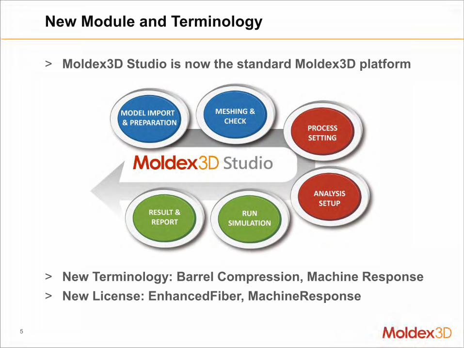
> Moldex3D Studio is now the standard Moldex3D platform
> New Terminology: Barrel Compression, Machine Response > New License: EnhancedFiber, MachineResponse
New Module and Terminology

Enhanced Usability New Capability Performance
Studio – New Standard Platform

7
> Allow going back anytime to pre-processing stage – Consistent model and project information through out – Provide option to copy or replace current project and model
> Benefit – Fully integration through modeling tools, analysis setup and post-
processing tools for user to switch anytime when needed
Enhanced Usability: All Tasks in One Platform
One Platform For
All
Modeling
Meshing Analysis
Post-process

8
> Support a variety of molding project and simulation – Co-injection Molding (CoIM), Bi-injection Molding (BiIM)、
Gas/Water Assisted Injection Molding (GAIM/WAIM), – Powder Injection Molding (PIM), Foam Injection Molding (FIM),
Chemical Foaming Molding (CFM), – Compression Molding (CM), Injection Compression Molding (ICM)
Enhanced Usability: Variety of Molding Simulation

9
> Directly and Intuitively make modification on color bar: – Provide color bar option when moving cursor on it – Allow pulling color bar to change it location (left/right) – Allow pulling Max/Min mark to change color fill range – Click and enter value to modify bar Max/Min value
Preference Setting : Color Legend
3 4 6 5 7
1. Change Fill Range 2. Change Color Bar Range 3. Banded Distribution 4. Inverse Color Legend 5. Reset Fill Range 6. Reset Color Bar Range 7. Move Color Bar (Left/Right)
10
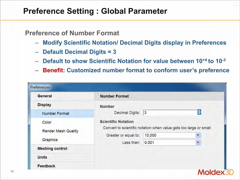
Preference of Number Format – Modify Scientific Notation/ Decimal Digits display in Preferences – Default Decimal Digits = 3 – Default to show Scientific Notation for value between 10+4 to 10-3
– Benefit: Customized number format to conform user’s preference
Preference Setting : Global Parameter

11
> Allow Show/hide control in Display Window such for Melt Inlet/Coolant Inlet/Gate/Valve gate/Sensor Node/Part IDs
> Allow saving and editing preference view option > Allow Language Pack download for Multi-Language interface
Other Usability Enhancements in Studio
Show/hide objects Show/hide marks
Language Packs will be provided with Service Pack

Higher Usability New Capability Performance
Studio – New Standard Platform

13
Support BDF format surface mesh file – Import Nastran BDF for surface mesh and then continue with
solid mesh generation in Moldex3D – Benefit: Convenient workflow for Nastran users
CAD Tool: Import of Nastran BDF file
14
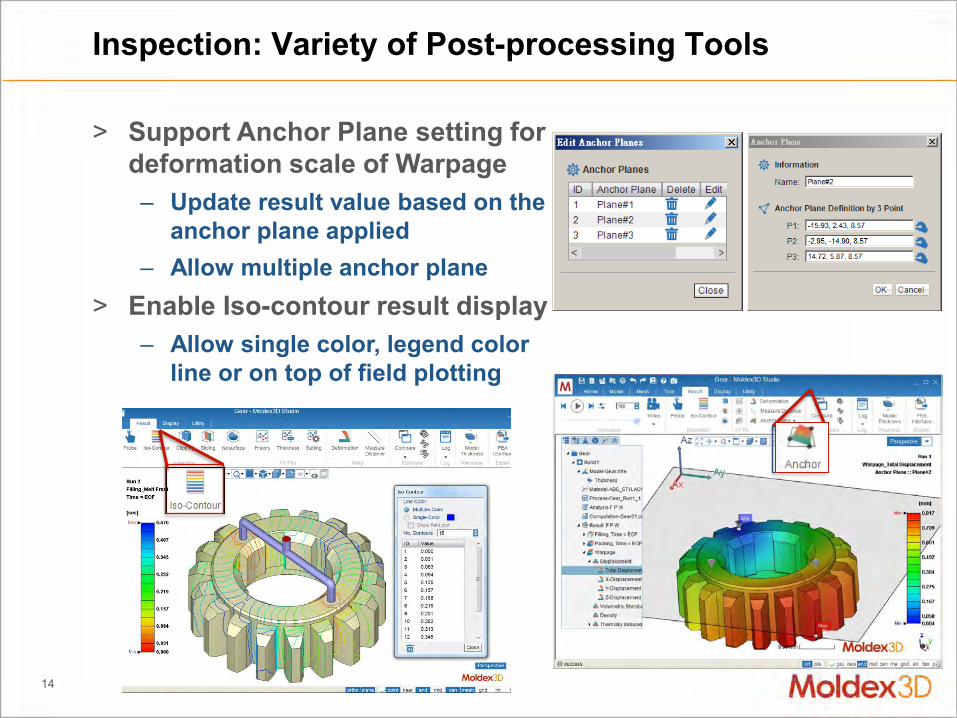
> Support Anchor Plane setting for deformation scale of Warpage – Update result value based on the
anchor plane applied – Allow multiple anchor plane
> Enable Iso-contour result display – Allow single color, legend color
line or on top of field plotting
Inspection: Variety of Post-processing Tools

15
> Deformation result display with scaling or mold compensation – Control scaling and compensation individually in each direction – The value of Measure function will updated for scaled result – Model export and anime for deformation or mold compensation
model
Inspection: Warpage Result and Export

16
> Plotting result change with time – Support local history on
Probe and Sensor nodes – Support global history of
molding properties – Display specific volume
history with reference line of PvT behavior
– Enable crystalline history
> XY plot customization – Allow combination of
different node and data – Allow data export as CSV
and JPG files
XY Plot : History Curve Plotting

17
> Plotting thickness direction variation curve – Inspect the variation inside
> Plotting result distribution – Add curve by Probe group – Add multiple time steps data
> Support Probe selection and data export (JPG & CSV)
XY Plot: Distribution Curve Plotting
R17 Beta4

18
> Provide quick edit function directly on XY Plot – Double click on different
place to modify plot setting
> Provide Plot setting wizard: – Directly launch on XY plot – X and Y axes format & title – Style change on legend /
font size / curve sort – Option to display model and
tracer on XY Plot
> Benefit: Customized style for performance in different company format presentations
XY Plot : Preference Setting

19
> Cross-group/time/result comparison – Compare results from different time, runs and result items – Provide flexible Sync setting for different purpose – Benefit: Compare result difference with controlled factor
Compare: Multi-window Result Comparison
20
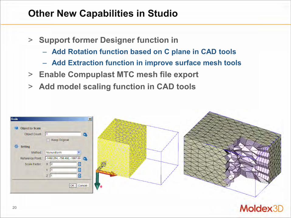
> Support former Designer function in – Add Rotation function based on C plane in CAD tools – Add Extraction function in improve surface mesh tools
> Enable Compuplast MTC mesh file export > Add model scaling function in CAD tools
Other New Capabilities in Studio

Higher Usability New Capability Performance
Studio – New Standard Platform

22
> File size 40% reduced > Memory usage 60% reduced > Up to 50X smooth rendering performance
Render: More Efficient Project Management
* Test mode Information: Cell Count: 4.7 Million Results Data: Filling (5 time-step) + Packing (5 time-step) +C+W
Project Studio R16 Studio R17File Size 2.59 4.06 2.59
0
2.6
5.2
GB
Reduced File Size
40%
Project Studio R16 Studio R17Memory 3.18 3.13 1.23
0
1.25
2.5
3.75
GB
Reduced Memory Use
60%

23
> New display kernel: Speed up project open and result reading – Save the time in data transfer and avoid RSV file issues
> Enhanced Clipping display with Velocity vector and Warpage Deformation results
> Render Enhancement: Improved Air Trap display accuracy – Allow superimposed with other type results display – Save data transfer time, file size and memory usage
Render : Enhanced Display Kernel

24
> Venting Analysis – Assign BC and venting
pressure profile > Pin Movement Simulation
– Pin Movement modeling and result display
> Fiber Orientation Prediction – Fiber Orientation and
Alignment Display > Compression Zone & Charge
– Assign BC and Property
Render: Advanced Analysis and Display
open

Solver Enhancement Advanced Analysis Machine Response & Characterization Fiber Analysis
Solver Capability

26
Important Factors for Injection Molding Simulation
Process Modeling - Modeling domain and procedures - Governing equations of molding process
Barrel, Screw, Nozzle
Filling, Packing, Cooling
Response and control
Material Modeling - Constitute equations of material - Material phase transition function
Fiber orientation modeling
Micromechanics modeling
Crystallization modeling
Viscoelastic modeling

27
> Cross check different material properties to ensure consistent material behavior for accuracy – Solver will launch checking and put result in analysis log – Checking criteria is according to basic material behavior
(transition point and etc..) consistency – Improper items will be listed for their possible reasons – Support for thermo-plastic material
Material: Enhanced Material Checking Kit
Viscosity, PVT, Cp, K…

28
> Predict flow rate and pressure drop of cooling channel, and heat dissipation of mold – Initially elevate mold up to operating temperature, maintain the
temperature during operation and compensate for heat losses > Adopt the pump performance curve (user input parameters)
– For evaluating the mold temperature controller whether its performance is sufficient or not
Cool : Mold Temperature Controller Advisor
Max. pressure requirement Total flow rate requirement
Cooling capacity requirement
_MoldTempReqired.csv
Evaluate with Controller’s Specification
Evaluate Select
Simulate
100
℃

29
> Example: Regloplas P161XL specification
Cool: Mold Temperature Controller Evaluation
Analysis requirements Evaluation
Step1 Max. pressure requirement 3bar
Refer to pump performance curve.P161XL need flow rate 120 (l/min)underpressure 3 bar.
Step2 Total flow rate requirement 280 l/min
280(l/min)/120(l/min) ≈at least need 3 temperature controller
Step3 Cooling capacity requirement 27kW
Refer to cooling capacity curve.,P161XL provide 80kW cooling capacity. That’s enough.
Pump performance curve
Cooling capacity curve https://kuwatec.nl/wp-content/uploads/2018/03/Kuwatec-Wilmod-Brochure-Regloplas-2017-ENG.pdf

Solver Enhancement Advanced Analysis Machine Response & Characterization Fiber Analysis
Solver Capability

31
> Jetting Prediction – Common slight jetting behavior in
the thick part – May cause some defect likes flow
mark, air trap….
> Simulation Trend Correction – Optical behavior – Cavity pressure – Warpage
> Advanced Molding Behavior
– Die swell – Buckling
VE: Common Application of Flow-VE Coupling Analysis
Decoupled
VE Coupled (High elasticity)

32
> Higher speed and stability calculation – Up to 2 times faster
> Improved material modeling for Flow and Structure VE – Consistency on model display and setting workflow
> More accuracy on Flow-VE coupling Simulation – Better prediction on vortex flow, warpage and optical behavior
VE : Enhanced Capability for Flow-VE Coupling
Flow VE Structure VE
Relaxation Spectrum
33
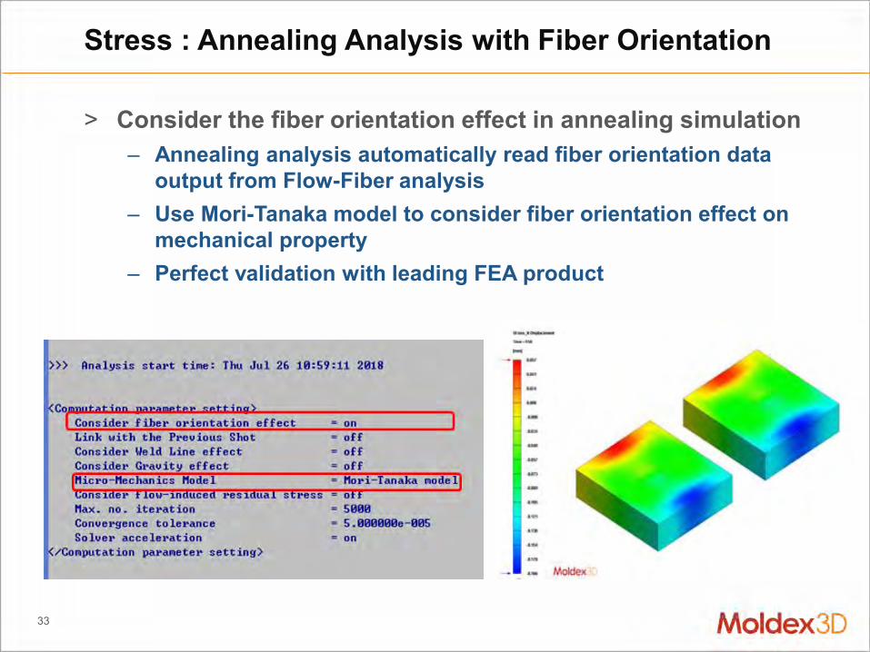
> Consider the fiber orientation effect in annealing simulation – Annealing analysis automatically read fiber orientation data
output from Flow-Fiber analysis – Use Mori-Tanaka model to consider fiber orientation effect on
mechanical property – Perfect validation with leading FEA product
Stress : Annealing Analysis with Fiber Orientation
34
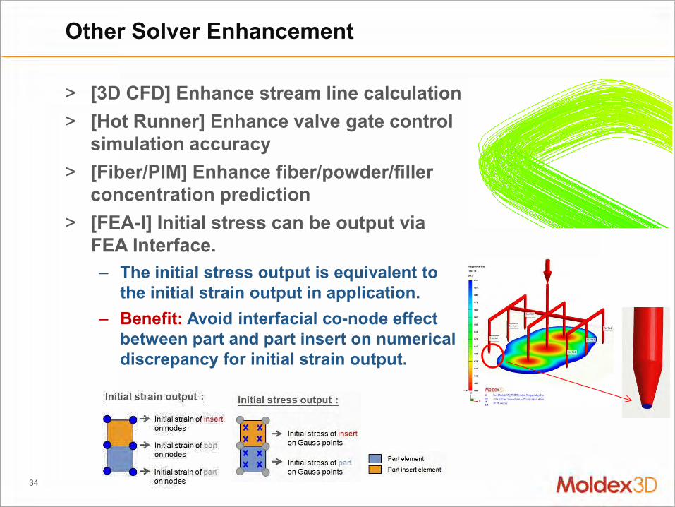
> [3D CFD] Enhance stream line calculation > [Hot Runner] Enhance valve gate control
simulation accuracy > [Fiber/PIM] Enhance fiber/powder/filler
concentration prediction > [FEA-I] Initial stress can be output via
FEA Interface. – The initial stress output is equivalent to
the initial strain output in application. – Benefit: Avoid interfacial co-node effect
between part and part insert on numerical discrepancy for initial strain output.
Other Solver Enhancement

Solver Enhancement Advanced Analysis Machine Response & Characterization Fiber Analysis
Solver Capability

36
> Consider the difference between operator process setting and actual injection behavior – Machine response can be highly
diversified for different type machines and controllers
Machine Response : Machine Response Simulation
Real
Consider Machine Response
NOT Consider Machine Response
Real
Consider Machine Response
NOT Consider Machine Response
Response
Prediction

37
> Can collaborate with barrel compression consideration – Solver calculation option with Machine mode – Virtual nozzle and barrel will be considered automatically
Machine Response : Melt Compressibility Effect inside the Barrel
Flow rate at screw head
Flow rate at nozzle
Nozzle Screw (Barrel)
Machine Response (Drive unit)
New in R17
Before R17

38
> Machine response with compressibility behavior inside barrel
Machine Response : The effect of Machine Response
0
20
40
60
80
100
0 0.5 1 1.5 2
Spru
re p
ress
ure
(M
Pa)
Filling time (s)
W/O Machine Response
W/ Machine Response
Experiment
39
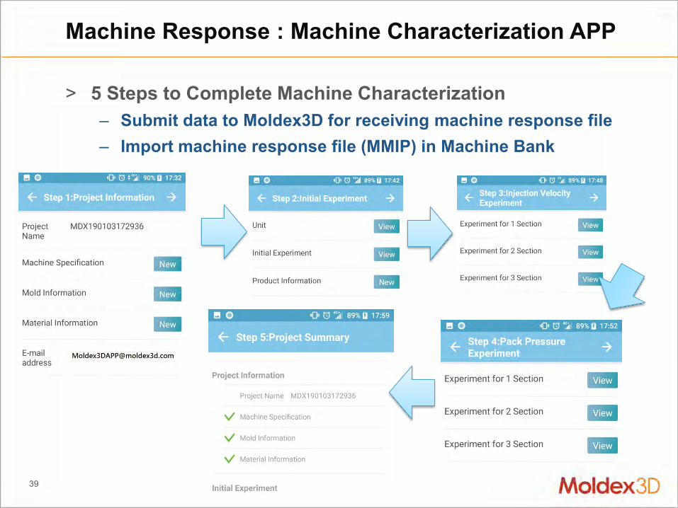
> 5 Steps to Complete Machine Characterization – Submit data to Moldex3D for receiving machine response file – Import machine response file (MMIP) in Machine Bank
Machine Response : Machine Characterization APP

40
> dditional license required – “MachineResponse”
Machine Response: Characterization for Specified Machine
Machine characterized data
Import machine data
Unique machine data is encapsulated in data bank

Solver Enhancement Advanced Analysis Barrel Compressibility & Machine Response Fiber Analysis
Solver Capability

42
Flow
Orientation
Viscosity
Stress
Fiber: Flow-Fiber Coupling – Analysis Theory
Decoupling
Coupling
Dτ 2
0
u
tgσσuuu
)()(t
τIσ p
)(),( RPRiARDHD AAAA MI CC
n
PTPT
1
*0
0
1
),(),,(
),,,( APT

43
> Apply two anisotropic viscosity models from collaborated research by Moldex3D (Ivor) and Purdue University (Pipes) – Favaloro-Pipes IISO model: Better for Compression Molding (CM) – Revised IISO model: Default, better for Injection Molding(IM) – Require additional license: EnhancedFiber – Benefit: advanced simulation of anisotropic flow behavior
induced by fiber orientation of FRP material
Fiber: Flow-Fiber Coupling – Computation Parameters

44
> Full coupled fiber-flow analysis to simulation anisotropic flow – Compression molding: GMT. SMC
• with high fiber concentration: >> 20 vol% – Effect of high fiber orientation on flow behavior
Fiber: Flow-Fiber Coupling for Compression Molding
Fully Coupled Decoupled

45
> Full coupled flow and fiber orientation simulation for anisotropic viscosity and flow in Injection Molding – flow advances faster near the edge than in the center
Fiber: Flow-Fiber Coupling for Injection Molding
Decoupled
Fully Coupled

46
> Flat fiber has different cross section shape to regular fiber
> Significant effect on improving warpage result in experiment
Fiber: Flat Fiber – New Filler to Improve Warp
http://www.nittobo.co.jp/business/glassfiber/frtp/hisff.htm

47
> [Fiber] Support Fiber analysis with flat fiber – Require additional license: EnhancedFiber – Additional filler option in Computation Parameter – Benefit: Expand Fiber analysis capability for new reinforced filler
Fiber : Flat Fiber Simulation & Computation Parameters

48
> By having this oval shape of glass fiber, various properties as a base material for injection molding are shown improved : – Fluidity – Dimensional stability – Tensile strength
Fiber: Flat Fiber – Warpage Improvement Validation
~60% improvement

RTM Solver Capability Foaming Molding Solution Other Molding Types
Molding Innovation

50
> 1. Auto Hybrid tool: – Extrude solid mesh from surface – Apply non-matching technology
> 2. Multiple layers from LS-Dyna draping result
RTM : Easier Mesh Preparation for RTM
User setting the ply information Auto hybrid tool Solid mesh
Support user to import multiple layers draping result.

51
> Output overflow amount through vent to LOG after analysis
> Set mold temperature profile in Curing stage – Manufacturer raises the mold temperature to reduce curing time.
RTM : Melt Overflow Data Output and Curing Mold Temperature Profile Setting
Ref:Effect of post-fill pressure and nanoclay on void morphology in resin transfer molded composites.

RTM Solver Capability Foaming Molding Solution Other Molding Types
Molding Innovation

53
> Foaming Analysis with Specified Expansion Ratio – Improved simulation accuracy validated with FOAMAT experiment
for fine material data and process conditions
CFM: Enhanced Foaming Kinetics Model
Temperature vs. time
Tem
pera
ture
[oC
]

54
> Consider bubble convection during FIM (Foam Injection Molding) Coreback process – To better observe bubble transportation during cavity expansion – Better stability and accuracy on bubble distribution prediction – Good result for moderate Coreback distance
FIM: Improved Coreback Simulation

RTM Solver Capability Foaming Molding Solution Other Molding Types
Molding Innovation

56
> Fully support Sink mark prediction for ICM process. – Compression part is modeled by compression zone
ICM: Sink Mark Output for ICM Simulation
2K-ICM Simulation Framework to Enable Design Optimization for Surface Aesthetics http://www.moldex3d.com/en/2018-gita-winners-company-n10/
0
0.01
0.02
0.03
0.04
1 2 3 4
Sink
Mar
k D
ispl
acem
ent
(mm
)
Position number
Injection molding
Injection compression molding

57
> The process set gate and fluid inlet on different side of cavity – GAIM use gas with lower thermal transport ability, and thus will
cause more core-out volume in part especially near inlet – Benefit: reduce flow mark by short-shot process and recycle the
material push back to barrel to avoid overflow waste
GAIM : Support Push-back Process

58
> New PVT model: Modified Tait Model (3) – To more accurately present compressibility change of PIM
(Powder Injection Molding) material under different pressure – Coefficient C becomes fitting instead of fixed parameter
PIM: New PVT Model

CAD & Mesh Tool Meshing Kernel Modeling Wizard
Pre/Post-processing Tools

60
> Allow locally modify thickness by scaling surface mesh
> Support to extract element – Consider feature line during
surface mesh generation > Enhance Unfillet Wizard
– Better Performance and Speed
BLM : Improve Surface Mesh
Original Result New Result

61
> Node seeding auto-refine for geometry runner system – Mesh refine around inlet/outlet of
geometry runner and cooling system – Adjust mesh parameter for runner and
cooling system > Full mold quick seeding function
– Support Edge to Face seeding mapping – Support seeding mapping from
Part/Part insert to other components
BLM: Node Seeding Auto-refined Enhancement

CAD & Mesh Tool Meshing Kernel Modeling Wizard
Pre/Post-processing Tools

63
> Add option for auto BLM offset ratio adjustment – Separated BLM parameters for part and other components
> Support Prism mesh element for Compression Zone – Add option to switch mesh type between BLM and Prism in wizard
with corresponding parameters to modify – Skip unsupported feature to avoid interference during mesh
generation (too large angle / nearly vertical / concave corners)
BLM: Mesh Generation Performance Enhancement

64
> Gate rebuild can keep surface mesh after matching faces
> Allow editing and fixing gate face BC – Show Gate Face BC when contact issue
found during mesh generation for users to manually fix it (Add/Remove BC)
BLM : Gate Rebuild Capability Enhancement

65
> Non-matching Moldbase / Mold Plate Meshing Enhancement
> Improved Node Seeding – Auto density control: Part、Runner、Gate、Cooling Channel、
Moldbase、Mold insert、 Mold Plate
> Check Model interference between Components
> Check Mesh Defect and Issue – Highlight Trouble point and Bad orthogonality
– Find and fix mesh interference
BLM : Non-matching Mesh Enhancement

66
> Hexa-based mesh kernel is available in eDesign Mode – Better to observe flow and thermal behavior especially near the
junction of part and runner
eDesign: Enable Hexa-based Runner Mesh
Hexa-based Structural Runner Mesh
Better Prediction of Flow Pattern and Temperature Distribution

CAD & Mesh Tool Meshing Kernel Modeling Wizard
Pre/Post-processing Tools
68
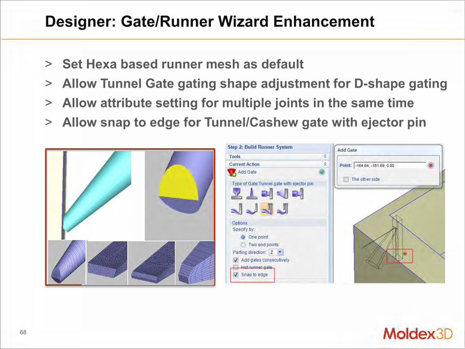
> Set Hexa based runner mesh as default > Allow Tunnel Gate gating shape adjustment for D-shape gating > Allow attribute setting for multiple joints in the same time > Allow snap to edge for Tunnel/Cashew gate with ejector pin
Designer: Gate/Runner Wizard Enhancement

69
> Enhance cooling channel template workflow – Improved user interface and template arrangement – Provide setting parameters according to selected template
Designer: Cooling Channel Wizard Enhancement

70
> Enable BLM max layer count adjustment
> Enhance RTM Wizard – Extrusion Solid Meshes from
Multi LS-DYNA Files > Reduce element count for Auto
IC Solid mesh generation – Support quad surface element
and solid mesh hexa cells – Allow BUMP node seeding
adjustment
Mesh: Moldex3D Mesh (on Rhino) Enhancement

Speeding Up Calculation Interface & Integration Database Update
Usability & Database

72
> Support Remote Computing with Microsoft MPI > Enhance Remote Computing to minimalize access request to
IT system and network
RC : Remote Computing Capability Enhancement

73
> Add overall progress ratio display for each analysis job > Allow window size adjustment for Computing Manager
– The adjusted window size will be kept when closed
RC : Remote Computing Usability Enhancement

Speeding Up Calculation Interface & Integration Database Update
Usability & Database
75
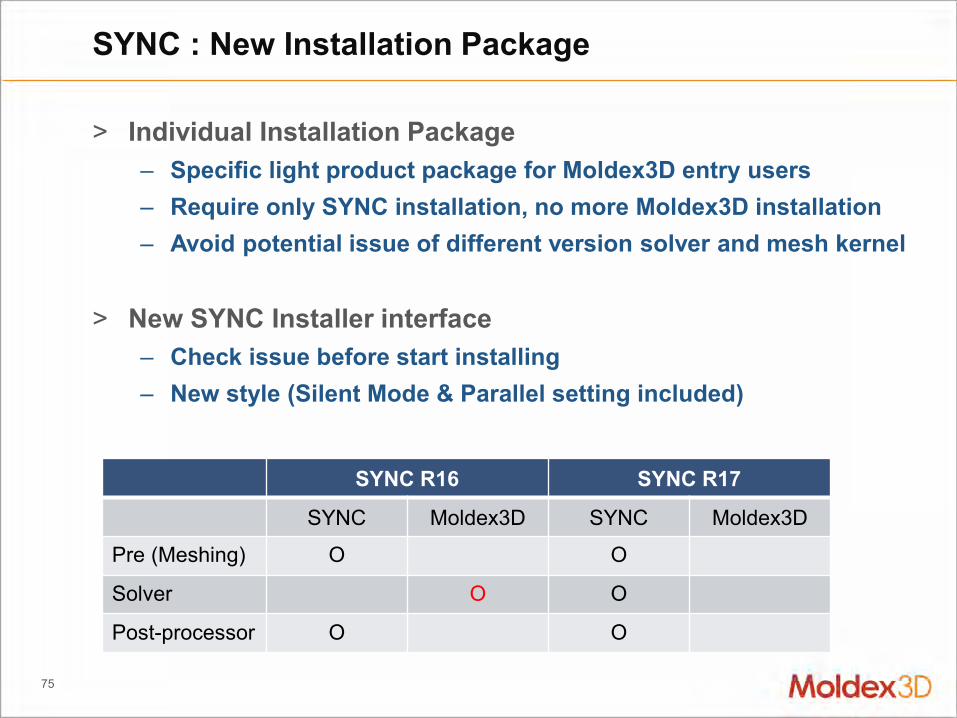
> Individual Installation Package – Specific light product package for Moldex3D entry users – Require only SYNC installation, no more Moldex3D installation – Avoid potential issue of different version solver and mesh kernel
> New SYNC Installer interface
– Check issue before start installing – New style (Silent Mode & Parallel setting included)
SYNC : New Installation Package
SYNC R16 SYNC R17
SYNC Moldex3D SYNC Moldex3D
Pre (Meshing) O O
Solver O O
Post-processor O O

76
> Geometry fixing workflow for mesh generation – Will remove bad faces during
mesh generation > Support Machine Interface and
Machine Response > Enhanced Report Wizard
– A variety of customized options
SYNC: Pre/Post Tools Enhancement

77
> Support Valve gate Control – Establish analysis tasks
with customized interface – Support the combinations
of different gate switch control
API: More Capability through API Control
Customer Defined IT
System Moldex3D Moldex3D API

Speeding Up Calculation Interface & Integration Database Update
Usability & Database
79
> [Material] Update material database – 39 thermoplastic materials are newly added
• PA(26), PFA(3), TPE(5), TPV(5) – 0 thermoset is newly added – 6 material information is updated for properties including
viscosity, PVT, specific heat and thermal conductivity • PA(4), TPE(3), TPV(2)
Material: Database Update

80
> Improved material search options: – Long Fiber / Mold Temperature / Melt Temperature / Structure VE
> Show Material Bank version in Content page – Ensure the latest material file for simulation accuracy
> No longer support ASC format as exterior source
Material: Material Wizard Usability Enhancement

81
> Add Machine Interface of BAIFENG mold temperature controller – Expand Machine Interface to mold temperature controller – Provide straightforward information for machine operator
> New injection machine and new Machine Interface – Add YIZUMI 444 injection machine to Machine Bank – Add Machine Interface: SUMITOMO/ Hwa Chin / Taichung Machinery
/JSW/Hai Tian and the corresponding machine controllers
Machine: New Added Machine Interface

82
> Support report format and content customization to show material/process information or key data (Max/Min/Avg/SD) – Use standard TAG items to modify report content – Support Max/Min/Avg/SD value, curve peak and scaled result – Support control through API
Report: Customized Report Format and Content
Template Derived PPT
Command Pool

www.moldex3d.com CoreTech System Co., Ltd.│Copyright© 2019 Moldex3D. All rights reserved.