Embed Size (px)
Citation preview


2MZ 25C/MZ 25S TECHNICAL INSTRUCTIONS
WARNING: If the information in this manual is notfollowed exactly, a fire or explosion may resultcausing property damage, personal injury or death.
WHAT TO DO IF YOU SMELL GAS• Do not try to light any appliance.• Do not touch any electrical switch; do not use any phone
in your building.• Immediately call your gas supplier from a neighbor’s
phone. Follow the gas supplier’s instructions.• If you cannot reach your gas supplier, call the fire
department.INSTALLATION AND SERVICE MUST BE PERFORMEDBY A QUALIFIED INSTALLER, SERVICE AGENCY ORTHE GAS SUPPLIER.
I . P R E S E N T A T I O N1 - DESCRIPTIONWall-mounted, condensing, gas-fired instantaneous waterheater for use with natural or LP gases in accordance withANSI Z 223.1 or CGA B149The following parts come fitted in a plain and stylishcover:
• a high performance, condensing finned tube heatexchanger.
• a premixing burner with a heat-resistant steel grate.• a gas valve.
• control panel and electrical fittings which regulate the waterheater and ensure smooth operation
• a heating circuit safety valve (43.5 psi / 3 bars).• a combined temperature/pressure gauge.• a condensate drain with built in condensate trap.• a circulating pump.• air eliminator.• an 2.1 gal (8 litres) expansion tank.• a by-pass (to be adjusted if the installation flow rate is too low).• a 3-way selector valve. (S model only)
M Z 2 5 C / M Z 2 5 S T E C H N I C A L I N S T R U C T I O N S
T A B L E O F C O N T E N T S
FOR YOUR SAFETY• Do not store or use
gasoline or otherflammable, vapors andliquids in the vicinity ofthis or any otherappliance.
I - PRESENTATION .......................................................... 21. DESCRIPTION ......................................................... 22. RANGE ..................................................................... 33. TECHNICAL SPECIFICATIONS .............................. 3
3.1 - Connection Dia. ............................................ 33.2 - Overall dimensions ....................................... 3
II - OPERATION................................................................ 41. PRINCIPLE OF OPERATION................................... 4
1.1 - Operating schematic (Dual function model) .. 41.2 - Operating schematic (Single function model) .. 5
2. CONTROL AND REGULATION ............................... 52.1 - Control panel ................................................. 52.2 - Diagram showing operating cycles, space . heat mode ..................................................... 52.3 - Thermal safety device ................................... 62.4 - 3 way-valve ................................................... 62.5 - Accessories .................................................. 6
3. BURNER .................................................................. 63.1 - Introduction ................................................... 63.2 - Gas unit ........................................................ 6
4. FAN .......................................................................... 65. HEAT EXCHANGER ................................................ 6
III - INSTALLATION.......................................................... 71. GENERAL ................................................................ 72. FITTING THE ANGLE MOUNTING BRACKET ........ 83. FITTING THE SPACER BACK PLATE (Optional) .... 84. FITTING THE CONNECTION BACK PLATE .............
(Optional) .................................................................. 85. PLUMBING CONNECTIONS ................................... 8
5.1 - Dual function model fitted without connections back plate .................................. 8
5.2 - Relief valve ................................................... 95.3 - Low temperature floor heating ...................... 95.4 - Condensate and venting connection ............. 95.5 - Pipe connections ........................................... 95.6 - Pressure/Flow rate curves ............................ 9
6. GAS CONNECTIONS............................................. 107. ELECTRICAL CONNECTIONS .............................. 10
7.1 - Original connection (no external control) with jumpers installed ......................................... 107.2 - Connection to external control .................... 107.3 - Circuit diagram (MZ 25 C) ........................... 117.4 - Circuit diagram (MZ 25 S) ........................... 12
8. COMBUSTION PRODUCTS EXHAUSTED BY.....BALANCED FLUE .................................................. 138.1 - LEAK-TIGHTNESS......................................... 15
IV - COMMISSIONING .................................................... 151. WARNING .............................................................. 152. COMMISSIONING .................................................. 16
2.1 - Check operating pressure .............................. 162.2 - Check gas flow rate ........................................ 162.3 - Changing gas type .......................................... 16
V - SERVICING .............................................................. 171. RECOMMENDED SERVICE PARTS ..................... 18
VI - ASSEMBLY/DISMANTLING .................................... 181. COVER ................................................................... 182. ELECTRICAL CONNECTION UNIT ....................... 183. BURNER ............................................................... 18
VII - DOMESTIC WATER HEATER ................................ 191. HEATER INCORPORATED INTO DUAL FUNCTION
MODEL ............................................................... 19VIII - MONITOR PRODUCTS, INC. (“MPI”) LIMITED...
WARRANTIES ......................................................... 20

3 www.monitorproducts.com
PRESENTATION
2 - RANGEFEATURES :
• Compact (14.2 inches deep / 361 mm)• Sturdiness ensured by using an oversized exchanger• Very high operating efficiency
3 - TECHNICAL SPECIFICATIONSGAS PROPERTIES. rated heat input MZ 25: 94 500 Btu/h(27.7 kW)** Heat input calculated on the higher heating value: H
Heating value H60 °F / 15.5 °C
BTU/foot3 / Mj/m3
Inlet pressureIWG / mmCE
Gas flow60°F / 101.3 Kpa
foot3/h / m3/hGas orificeinch / mm
P2(outlet pressure)
IWG / mmCEAir burner pressure
IWG / mmCE P
Air pressostatIWG / mmCE
Heat inputLH
BTU/h.kWAir orificeInch / mm
Natural gas
1075 / 40.1
7.0 / 177.8
87.9 / 2.49
0.213 / 5.4
2.8 / 71
1.57 / 40
1.57 / 40
85040 / 24.994500 / 27.7
1.14 / 29
LP gas
2500 / 93.1
11.0 / 279.4
37.8 / 1.07
0.138 / 3.5
5.50 / 140
1.57 / 40
1.57 / 40
88455 / 25.994500 / 27.7
1.22 / 31
DOMESTIC WATER FLOW RATET 54°F (30°C) MZ 25: 2.91 gal/min (11 l/min)
MINIMUM SYSTEM WATER FLOW RATE3.52 gal/min - 800 l/hWATER PRESSUREHeating pressure: maxi 43.5 PSI (3 bars) - mini 14.5 PSI (1bar)Hot water pressure: maxi 87 PSI (6 bars)MAXI OPERATING FLOW TEMPERATURE176°F (80°C)ELECTRICAL SUPPLY120V - 60 HzCOMBUSTION PRODUCTSMax temperature: 176°F (80°C)Flow rate 32°F (0°C) 14.7 PSI (1013 mbar): 1201 foot3/h -34 m3/hBalanced flue 3” (75 mm) diameter: Max temperature: 266°F(130°C).
3.1 - CONNECTION DIAMETERModels MZ 25
Combustion Products 2.55 inches (75 mm) diameter PPMZ balanced flue - (1, fig. 1)
Gas connection 3/4" (0.79/1.06 inches) - (20/27 mm)diameter - (2, fig. 1)
Water heater 1" (1.02/1.34”) -connections (26/34 mm) diameter - (3, fig. 1)
Domestic hot 3/4" (0.79/1.06”) - (20/27 mm)water connections diameter - (4, fig. 1)
Condensate 1.26” (32 mm) diameter PVC -connections (5, fig. 1)
3.2 - OVERALL DIMENSIONSSingle function model
Duel function model
Inches mm
A 29.9 760
B 14.2 361
C 3.9 100
D 3.1 78
E 2.6 66
F 4.1 104
G 10.3 262
H 1.8 45
I 11.2 283,5
J 6.7 170,5
K 2.4 60
L 20.9 530
M 2.7 67,5
N 1.6 42
O 10.9 277
P 0.24 6
Q 21.3 540
R 3.2 82,5

4MZ 25C/MZ 25S TECHNICAL INSTRUCTIONS
OPERATION
1 - PRINCIPLE OF OPERATIONThe wall-mounted condensing gas-fired water heater makesmaximum use of the energy yielded by the gas combustionprocess. Using its “super-exchanger”, the MZ recovers thesensible heat from the combustion products, with an efficiencyof about 12% greater than that of a traditional water heatereven without condensing. If the flue gases are evacuated atthis stage of combustion, they are at temperatures of 392°Fto 572°F (200°C to 300°C).These flue gases still contain some of the sensible heat and
in particular appreciable amounts of latent heat in the form ofwater vapor. By routing the heating return through the bottomof the exchanger/condenser at a temperature of less than127.4°F (53°C), the flue gases will condense. Thiscondensation allied to the high performance of the exchangerresults in an energy saving of up to 30% compared toconventional equipment. As the phenomenon of condensationonly occurs for heating return temperatures of below 127.4°F(53°C), the operating efficiency of the heating installation willincrease as the average annual heating return temperaturedecreases.
1) Gas valve 2) Flue 3) Sight glass 4) Ignition electrode 5) Gas burner 6) Ionization probe 7) High limit stat 195°F (90°C) 8) Ignition transformer 9) Air Fan10) Differential air pressure switch11) Air eliminator
12) Gas supply13) Control panel14) Expansion vessel15) Connection box16) Condensate drainage siphon trap17) Exchanger with finned tubes18) Heating flow19) Thermostat sensors20) Heating return21) Circulating pump22) Safety valve
23) By-pass24) Flow switch25) DHW thermostat26) DHW cylinder27) Heating coil HW production28) 3 Way valve29) Hot water outlet30) Cold water inlet31) Insulation
I I . O P E R A T I O N
1.1 - OPERATING SCHEMATIC (MZ 25S)Fig. 2
5 www.monitorproducts.com
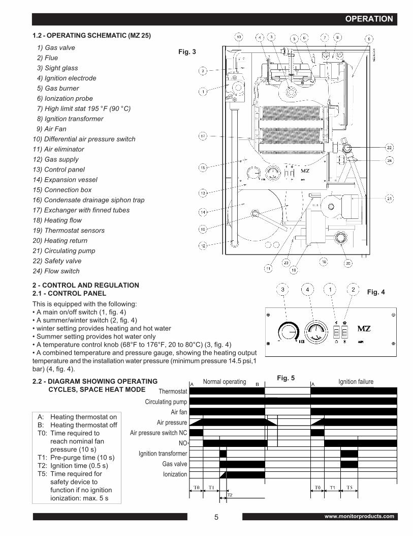
1) Gas valve2) Flue3) Sight glass4) Ignition electrode5) Gas burner6) Ionization probe7) High limit stat 195 °F (90 °C)8) Ignition transformer
9) Air Fan 10) Differential air pressure switch 11) Air eliminator 12) Gas supply 13) Control panel 14) Expansion vessel 15) Connection box 16) Condensate drainage siphon trap 17) Exchanger with finned tubes 18) Heating flow 19) Thermostat sensors 20) Heating return 21) Circulating pump 22) Safety valve 24) Flow switch
1.2 - OPERATING SCHEMATIC (MZ 25)
Fig. 3
2 - CONTROL AND REGULATION2.1 - CONTROL PANELThis is equipped with the following:• A main on/off switch (1, fig. 4)• A summer/winter switch (2, fig. 4)• winter setting provides heating and hot water• Summer setting provides hot water only• A temperature control knob (68°F to 176°F, 20 to 80°C) (3, fig. 4)• A combined temperature and pressure gauge, showing the heating outputtemperature and the installation water pressure (minimum pressure 14.5 psi,1bar) (4, fig. 4).
Fig. 4
ThermostatCirculating pump
Air fanAir pressure
Air pressure switch NCNO
Ignition transformerGas valveIonization
A: Heating thermostat onB: Heating thermostat offT0: Time required to
reach nominal fanpressure (10 s)
T1: Pre-purge time (10 s)T2: Ignition time (0.5 s)T5: Time required for
safety device tofunction if no ignitionionization: max. 5 s
2.2 - DIAGRAM SHOWING OPERATING CYCLES, SPACE HEAT MODE
Fig. 5Normal operating Ignition failure
OPERATION

6MZ 25C/MZ 25S TECHNICAL INSTRUCTIONS
OPERATION
2.2.1 - OPERATION FLOW CHART (control unit S 89 E 1058 B)
<
120V-60 HZON-OFF
DHWThermostat
3 way valve onDHW module
Winter/Summer
Room thermostat(1) or jumper
Circulating pumpRoom thermostat
(2) or jumper
Flow switch
Air fan
Air pressure switch
Safety control box
Prepurge time (10s)
Flue highlimit stat
Water heaterthermostat
Water highlimit stat
Ignition transformater
Safety shut down
Manual reset ofthe safety Gas valve
opening
1st setting-ignitionand flame check
YES
Ionisation flamecontrol
YES
Shut down
Shut down
OFF
ON
NO
YES
Summer
Winter
Nox
NO
NO
NO
Not shut down
Not shut down
Burner + air fan stopped
Burner + air fan stopped
Burner + air fan stopped
Burner + air fan stopped
Fanpermanetlyon, burneroff
x
Stop
<
<
>
>
>
>
>
>
>
>
Fig. 6
2.3 - THERMAL SAFETY DEVICEThe unit is equipped with a overheatsafety thermostat operating at 195°F(90°C) with manual reset (7, fig. 2 andfig. 3)
2.4 - 3 WAY-VALVEThe 3 way water valve is controlled by thedomestic hot water thermostat (25, fig. 2 andfig. 3).When domestic hot water heat is required(temperature <149°F / 65°C). The 3 way valvedelivers 100% of the available heat to thewater heater.2.5 - ACCESSORIESThe wall-mounted unit incorporates all of theaccessories needed for smooth operation:expansion tank, circulating pump, safetyvalve, air eliminator, drain tap, pressuregauge, heating water filter and condensatedrain trap.
3 - BURNER3.1 - INTRODUCTIONThe unit’s burner is a blown air burner withpremixing. The flame burns on a grate madefrom heatresistant steel.This technique gives a perfect gas mixtureand a combustion which is sharp, silent, andwell-adapted to the combustion unit.
3.2 - GAS UNIT• Gas regulatorThe gas regulator ensures the correct heatoutput from the appliance by regulating thegas burner pressure whatever the supplypressure (max input P = 20 IWG).• Gas valveThe gas valve has a solenoid valve whichcontrols the gas supply to the burner. Thissolenoid valve has a low power consumptionand can operate constantly and silently.
• FilterThe unit input is fitted with a screen filter which protects itagainst any impurities carried in the gas supply.4 - FANThe fan, specially developed for the MZ, is very efficient andquiet. Its turbine provides a flow rate with a low sensitivity topressure variations.
5 - HEAT EXCHANGERThe heating assembly has a particularly well-designed bodyconsisting of two distinct parts:• The square-section upper part constitutes the coldcombustion chamber with its surrounding layer of water. Asight glass allows the flame to be observed.• A “ super exchanger ” captures almost all the sensible heatand latent heat contained in the combustion products.
Fig. 7
Ignition electrode
Airpressureswitch testpoint
Combustion chamber unit pressure
Air pressure switchIonisation probe
Pressuretap P2
Gas pressureregulator
Servo-system
Pressuretap P21
Air fan
Ignition acceleratorSolenoid
Gas valve

7 www.monitorproducts.com
INSTALLATION
1 - GENERALThe installation must conform with one or more of thefollowing, as applicable:• Local codes or, in the absence of local codes, the National
Fuel Gas Code, ANSI Z 223.1 / NFPA 54 or Natural Gasand Propane Installation Code CSA B149.1.
• Can - CGA B149 installation code and/or local installationcodes.
• The National Electrical Code ANSI/NFPA No.70.• CSA Standard C22.2 No.0 and Canadian Electrical Code
Pt.1.This appliance must be grounded in accordance with thesecodes.The unit must be located in an area where water leakagefrom the unit or the connections will not result in damage tothe area adjacent to the unit or to lower floors of the structure.When such locations cannot be avoided, it is recommendedthat a suitable noncorrosive drain pan, adequately drained,be installed under the unit.The maximum inlet gas pressure must not exceed the valuespecified and the minimum value listed is for the purpose ofinput adjustment.If the water heater is installed in a closed water supply system,such as one having a back flow preventer in the cold watersupply line, means shall be provided to control thermalexpansion.Contact the water supplier or local plumbing inspector on howto control this situation.For the MZ 25 C is the water pressure exceeds 40 psi installan approved pressure regular set to 40 psi.The installing technician shall install a relief valve in the supplypipe of primary hydronic heating circuit. The valve shall bereadily accessible for servicing or replacement. The valvemust comply with the ANSI/ ASME Boiler and Pressure VesselCode, section IV. One typical valve is Watts regulator modelpoXL4, 150 psi. Equal alternate valves are also acceptable.When installing this valve no shut off valve is to be placedbetween the relief valve and the unit. The discharge from thisrelief valve must be conducted to a suitable place for disposalwhen relief occurs and no reducing coupling or otherrestriction shall be installed in the discharge line. Thisdischarge line shall be installed to allow complete drainageof both the valve and the line.The relief valve must be located so that if it operates all waterwill be discharged to a location which will not impinge on anyperson or damage any property.The preferred method is to pipe the relief valve discharge toa floor drain or a safe floor area near a floor drain.Manually operate the pressure temperature relief valve atleast once a year.Note: Canadian units come equipped with a relief valve whichmust be installed by service technician.
If the temperature pressure relief valve on the appliancedischarges periodically, this may be due to thermal expansionin a closed water supply system. Contact the water supplieror local plumbing inspector on how to correct this situation.Do not plug the temperature and pressure relief valve.Lighting and Shutdown Instructions are detailed on a labellocated inside the hinged front cover of the unit. These mustbe read and understood by all service personnel.WARNING ! - All areas adjacent to, and surrounding, thisunit must be kept free from combustible materials, gasoline,and other flammable vapors and liquids.
I I I . I N S T A L L A T I O N
2 - FITTING THE ANGLE MOUNTING BRACKETFig. 8
ModelsABCD
E miniF miniG miniH miniI mini
J*
MZ C inches/mm6.7/1703.9/100
19.5/49510.4/2650.5/12.70.5/12.76/152.4
24.0/609.636.0/914.4
0
MZ S inches/mm11.8/300
3.2/8019.5/49510.4/2650.5/12.70.5/12.76.152.4
24.0/609.636.0/914.4
0

8MZ 25C/MZ 25S TECHNICAL INSTRUCTIONS
Fig. 11
INSTALLATION
3 - FITTING THE SPACER BACK PLATE (optional)The spacer back plate allows pipe work to be passed behindthe water heater where the installation pipes arrive fromabove.ASSEMBLY• Fit the angle mounting to the wall (mounting delivered with
the water heater).• Hook the spacer back plate on to the angle mounting.• Hook the water heater on to the spacer back plate.
4 - FITTING THE CONNECTION BACK PLATE (optional)The connection back plate allows installation pipe work to beprefabricated, before fitting the water heater. It is equippedwith the angle mounting for attaching the water heater to the
Fig. 10
MZ S MZ C
Fig. 9
Spacerback plate
Gas Supply
Fixingscrew
Pipingway
Condensate drain
Heating outlet
Heating flow
45
5 - PLUMBING CONNECTIONSAll connections are made at the bottom of the rear of thewater heater. When operating the MZ, it is ESSENTIAL tomaintain a CONSTANT minimum flow rate of 3.52 gal/min(800 liters/h) through the water heater. Consequently, if theheating installation has been designed for a lower flow rate,the by-pass has to be adjusted (23, fig. 2 and fig. 3). Seesection “ Commissioning “. When the installation is fitted withthermostatic valves and does not have a differential pressureoverflow valve, adjust the by-pass with the thermostatic valveclosed.
5.1 - MZ 25S FITTED WITHOUT CONNECTIONS BACK PLATE
wall. It also includes the stop valve to be fitted on the gaspipe. Backing plates exist for all models.

9 www.monitorproducts.com
INSTALLATION
is the gas supply ¾ inch (20/27 mm) Ø.5.5.1 - FILLING THE INSTALLATION WITH WATERThe MZ water heater has two air purge valves, one on theheating outlet, the other on the domestic hot water heater(for the dual function model). Ensure that the water heaterand installation are properly purged by increasing the waterpressure to at least 14.5 psi (1 bar) (pressure gauge). Checkthat it is fully purged again a few days after commissioning.
5.6 - PRESSURE/FLOW RATE CURVES5.6.1 - CIRCULATING PUMP
5.6.2 - HOT WATER GENERATOR .P CONDENSING EXCHANGER
UPS 15-42 F (3-SPEED MOTOR) 60 Hz
Capacity in U.S GPM
Tota
l hea
d in
feet
Fig. 14 MZ 25 C/S HEAT EXCHANGERPRESSURE DROP
Pre
ssur
e dr
op
Flow rate
Fig. 13
When system requires water for space heating attemperatures higher than required for other uses a meanssuch as a mixing valve shall be installed to temper the waterfor those uses in order to reduce scald hazard potential. Seepiping diagram below:
5.2 - RELIEF VALVEA temperature and pressure relief valve listed as complyingwith the Standard for Relief Valves and Automatic Gas Shut-off Devices for Hot Water Supply Systems, ANSI Z21.22, shallbe installed at the time of installation of the heater in thelocations provided or specified by the manufacturer. Localcodes shall govern the installation of such relief devices. Forsafe operation of the water heater, the relief valve(s) mustnot be removed or plugged.5.3 - LOW TEMPERATURE FLOOR HEATINGThe MZ water heater is designed to be connected to a lowtemperature heating circuit. For most such applications 115°F(45°C) maximum output temperature is adequate. Thereforeit is recommended the unit’s space heating thermostat controlknob stops (3, fig. 4) be set to 115°F (45°C). Put the stops at25 and 12 (figures inside the knob). Put the water heater onand check the maximum temperature on the thermometer.An additional 140°F (60°C) safety thermostat must also befitted on the unit’s heating circuit flow outlet.5.4 - CONDENSATE AND VENTING CONNECTIONThe unit is designed to drain condensate (from the bottom ofthe combustion chamber and the combustion products flue)by a condensate trap at the bottom of the heating unit. Thecondensate trap, which can be accessed for inspection,should be connected in PVC 1,26 inches Ø (32 mm) to thewaste water system through a properly trapped drain. When
installing, remember to fill the condensate traps with waterbefore firing. They should be inspected twice a year. Noreducing coupling or other restriction is allowed.
5.5 - PIPE CONNECTIONSAll the pipe junctions are located at the rear of the MZ waterheater. Viewed from the rear, these are (from the left) thedomestic cold water pipe junction, then the domestic hot wateroutlet ¾ inch Ø (20/27 mm) . Next comes the heating return,then the heating outlet 1 inch Ø (26/34 mm) . Finally on right
Fig. 12 3 way mixing valve
Domestic hotwater from unit
Domestic coldwater fromhousehold
supply
Warm water topoint of use

10MZ 25C/MZ 25S TECHNICAL INSTRUCTIONS
Fig. 15 PowerSupply
Hot
INSTALLATION
5.6.3 - BY-PASS SETTING
Fig. 15
Flow rate
0 : Closed8: Fully open2 to 6 : Number of turns, countingfrom the “closed” position
Pre
ssur
e dr
op fo
r bui
lt-in
by-
pass
as a
func
tion
of s
ettin
g
6 - GAS CONNECTIONSThe appliance and its individual shut-off valve must bedisconnected from the gas supply piping system duringany pressure testing of that system at test pressures inexcess of ½ psi (3.5 kPa). The appliance must be isolatedfrom the gas supply piping system by closing its individualmanual shut-off valve during any pressure testing of thegas supply piping system at test pressures equal to or lessthan ½ psi (3.5 kPa).
• The appliance and its gas connection must be leak testedbefore placing the appliance in operating.The gas inlet diameter is ¾ inches (20/27 mm). The gassupply pipe must be fitted with a ¼ turnstop valve locatedin an easily accessible place. After commissioning, checkthat the pressure tapping points are properly closed andcheck the general leak tightness of the gas circuit (forexample user a foaming product or a U-Tube).Always purge through the gas pipe work beforecommissioning the appliance (in order to get rid of anyparticles produced by welding or threaded joints).
• The pipe supplying gas to the hot water heater mustnot cause a pressure loss of more than 0.4 inches (1mbar WG).
7 - ELECTRICAL CONNECTIONSThe appliance, when installed, must be grounded inaccordance with local codes or, in the absence of local codes,with the National Electrical Code, ANSI/NFPA 70 and the CSAstandard “Canadian Electrical Code” C22.1.7.1 - ORIGINAL CONNECTION (NO EXTERNAL CONTROL) WITH JUMPERS INSTALLED
Observe the correct polarity for live (L)and neutral (N)This appliance must be groundedThe power supply must be protectedby a 6A fuseAll internal electrical components havebeen pre-wired. No attempt should bemade to connect electrical wires to anyother location except the terminals asdesignated in fig. 16.
7.2 - CONNECTION TO EXTERNAL CONTROL7.2.1 - USING A ROOM THERMOSTAT TO CONTROL THE BURNER• Burner stopped when the room thermostat switches off.• Heating circulating pump continues to run after the
thermostat switches off.
• Domestic hot water production continues even when roomthermostat is switched off.
Room thermostat connected between T2 and T3 afterremoving jumper T2/T3). Jumper T1/T2 remains in place.7.2.2 - USING A ROOM THERMOSTAT TO CONTROL
THE BURNER AND HEATING CIRCULATINGPUMP SIMULTANEOUSLY
• Burner stopped when the room thermostat switches off.• Heating circulating pump continues to run after the
thermostat switches off.• Domestic hot water production stops when room thermostat
is switched off.
Hot
PowerSupply
RoomThermostat
Fig. 17
Room thermostat connected between T1 and T2 afterremoving jumper T1/T2). Jumper T2/T3 remains in place.
Hot
PowerSupply
RoomThermostat
Fig. 18

11 www.monitorproducts.com
INSTALLATION
Fig. 19
7.3 - CIRCUIT DIAGRAM (MZ 25C)

12MZ 25C/MZ 25S TECHNICAL INSTRUCTIONS
INSTALLATION
Fig. 20
7.4 - CIRCUIT DIAGRAM (MZ 25S)

13 www.monitorproducts.com
INSTALLATION
8 - COMBUSTION PRODUCTS EXHAUSED BY BALANCED FLUE

14MZ 25C/MZ 25S TECHNICAL INSTRUCTIONS
INSTALLATION
A balanced flue must beinstalled when the walladjoining the water heatergives onto the outside in awell ventilated location. Awater heater installed in thisway possesses a sealedcombustion circuit, com-pletely independent of theventilation circuit for therooms.The balanced flue outletmust be located at least 1.31
The flue may be mounted to the right , to the left, or directlybehind the water heater. Its maximum length must not exceed
The MZ is supplied with a standardlength flue which can be used to runthrough a wall up to 1.64 foot thick (0.5m) located directly behind the waterheater.
Fig. 21
DimensionsAB
C miniDEF
Inches5.434.336.0
2.952.762.64
mm138110
152.4757067
13.12 feet (4 meters). The flue gasexhaust tube Ø 2.95 inches (Ø 75 PP)must slope downward towards theoutside at 0.12 inches/foot * (1 cm permeter) to avoid accumulation of rainwater in the vent-air intake system.
foot (0.4 m) from any opening window and1.97 foot (0.6 m) from any air ventilationopening (see regulations). Two balanced flueoutlets (from two distinct adjacent MZ units)must be at least 1.97 foot (0.6 m) apart.
For greater lengths, or when the connection is to the right orleft of the hot water heater (13.12 feet, up to 4 m), specifywith your order.
Positioning slot
Polypropylene dia. 75Dia. 2.95”
PVC dia. 110Dia. 4.33”
Positioning stud
Fig. 22
702.8”
Air tube ends level with the outsideof the wallDrain slope towards
outside 0.12 inches/foot (1 cm/m)
Inspectionhatch screw
Flue gas outlet2.95” (PP dia.75)
Air Inlet4.33” (PVC dia. 110)
1) The three recommended distances (code of practice)2) Outlet under balcony or roof3) Outlet on a balcony4) Roof outlet (refer to factory)5) Outlet near to a corner
All dimensions are the minimum permissible

15 www.monitorproducts.com
INSTALLATION-COMMISSIONING
A public or private highway where a flueoutlet is located includes:• public or private pavement• pedestrian walkway• traffic route• alleyway• stairway (including landings and steps)
( No.2) Approved extension: 13.12 feet (4m)
( No.3) Approved extension: 13.12 feet (4m)
8.1 - LEAK-TIGHTNESSThe MZ water heater has a sealedcombustion circuit. Take care tokeep the various seals in goodcondition (cover, flue box, etc.).Replace if necessary. The variouselbows and connection pieceslocated on the flue gas exhaustroute and on the air intake must befitted in a leak-tight manner in orderto avoid flue gases recycling.
PVC tube,4.33”diameter (110 mm )
Polypropylene tube2.95” diameter (75mm)
Elbow
Junction box
Screw
Positioner
Positioning stud Fig. 23
I V. C O M M I S S I O N I N G1 - WARNINGIf you do not follow these instructionsexactly, a fire or explosion may resultcausing property damage, personal injuryor loss of life.
Should overheating occur or the gas supply fail to shut off,turn off the manual gas control valve to the appliance.
Do not use this appliance if any part has been under water.Immediately call a qualified service technician to inspect theappliance and to replace any part of the control system andany gas control which has been under water.Before commissioning the appliance, the installer should:• check that the gas circuit is leak-tight
• carefully flush out the gas pipes. Where the installation isnew, the purge serves to evacuate the air that is containedin the pipes so that the water heater has sufficient fuel.The presence of air in the gas prevents the burner fromlighting and results in the flame control unit safety devicecutting in. This applies to a new installation running oneither natural gas or LPG. For the latter, the storage tankmust also be flushed properly before commissioning.
All necessary safety precautions shouldbe taken when venting the gas.
Flushing the gas will also have the effect of removing anyoxide particles from the pipes produced during brazing• check that the flue gas outlet is leak-tight and that
combustion products can pass freely through this conduit;

16MZ 25C/MZ 25S TECHNICAL INSTRUCTIONS
COMMISSIONING
• check the appearance of the flame through the roundobservation window inside the hinged door just above thecontrols. The flame’s blue hue should almost completelyfill the round observation window.
• check that the installation is filled with water. The waterpressure should = 21.75 psi (1,5 bars), the radiators arepurged and the valves open (Attention! the pressure mustnot drop below 14.5 psi (1 bar);
• check that the electricity supply is connected correctly:120 V - 60 Hz, with correct polarity;
• check that the condensate outlet is connected,• check that the siphon trap is filled with water.(S model only): The domestic hot water thermostat is factoryset to its lowest temperature position. If it becomes necessaryto adjust this position it recommended that for energyefficiency the setting be kept at the minimum watertemperature consistent with the consumers needs.The preferred starting point is 115°F (48°C). Keep in mindthere is a hot water scald potential if the thermostat is set toohigh.When operating the appliance for the first time, the installermust verify• that the governor works properly;• that the flame control works properly;• the burner setting: CO, C02After the unit is installed select the nearest hot water faucetand let the water run until it is as hot as it will get. If thetemperature of the water has a risk of scald temperaturesreduce the DHW thermostat safety limit setting until the watertemperature has cooled to a safe level.
2 - COMMISSIONING• Open the manual valve on the gas inlet• Switch on the main heating switch• Set the on/off switch on the control unit to the on position• Put the CIRCULATING PUMP switch to the “winter”
position. In the “summer” position, the circulating pumponly works when the domestic hot water tank requiresheating (on the Dual Function Model)
• Adjust the by-pass setting: on installations where the flowrate is less than 3,52 gpm (800 l/h), the water flow ratethrough the water heater heat exchanger has to be adjustedGRADUALLY, by means of the by-pass (23, fig. 2 and fig.3) until the flow detector is triggered. All the thermostaticvalves in the installation must be kept shut during thisadjustment.
Sensors
By-pass spindle
Heating flow
Fig. 24
Heatingreturn
By-pass tube
• Burner adjustment: this is factory preset to obtainsatisfactory operation. However, when commissioning, itis necessary to carry out the following checks, with theburner operating:
2.1 - Check operating pressure• P1:Supply pressure• P2:Regulator valve output pressure• Adjusting gas pressure regulator:
• Turn to the right to increase the pressure• Turn to the left to decrease the pressure.
2.2 - Check gas flow rate Flow rate given at 59°F (15°C),14.7 psi (1013 mbar)
IWG = Inches of water pressure
2.3 - Changing gas type
The water heater is preset for natural gas. This operationmust be carried out by a qualified person When changing topropane gas (LP), use gas reducer in burner gas inlet (ref:conversion set). Then check the P2 gas pressure (outlet gasvalve) according to the framed indications. Be careful to checkP2 gas pressure with the cap properly screwed on thegovernor because of the air pressure action through thegovernor breather. (Gas pressure increase about 2 incheswhen cap mounted). When the conversion is made, checkthe gas soundness with burner ignited and stick the labelcorresponding to the new gas.
FOR YOUR SAFETY READ BEFORE OPERATINGWARNING: If you do not follow these instructions exactly,a fire or explosion may result causing property damage,personal injury or loss of lifeA This appliance does not have a pilot. It is equipped with
an ignition device which automatically lights the burner.Do not try to light the burner by hand.
B BEFORE OPERATING smell all around the appliance areafor gas. Be sure to smell next to the floor because somegas is heavier than air and will settle on the floor.WHAT TO DO IF YOU SMELL GAS• Do not try to light any appliance.• Do not touch any electric switch; do not use any phone
in your building.• Immediately call your gas supplier from a neighbors
phone. Follow the gas supplier’s instructions.
Ø Air reducerInlet pressure
Outlet pressureØ ReducerGas flow
60°F 1.01,3 kPACO2CO
inches/mmP1 IWG/mmCEP2 IWG/mmCE
inches/mmFeet3/h
m3/h%
ppm
NaturalGas
1.14/297.0/177.8
2.8/710.213/5.4
87.92.499.530
LP gas1.22/31
11.0/279.45.5/140
0.138/3.537.81.0710.750
Table of gas flow rates
17 www.monitorproducts.com
• If you cannot reach your gas supplier, call the firedepartment.
C Use only your hand to push in or turn the gas control knob.Never use tools. If the knob will not push in or turn byhand, don’t try to repair it, call a qualified servicetechnician. Force or attempted repair may result in a fireor explosion.
D Do not use this appliance if any part has been under water.Immediately call a qualified service technician to inspectthe appliance and to replace any part of the control systemand any gas control which has been under water.
OPERATING INSTRUCTIONS1 STOP ! Read the safety information above on this label.2 Set the thermostat to lowest setting3 Turn off all electric power to the appliance.4 This appliance has a sealed combustion chamber. DO
NOT ATTEMPT TO LIGHT THE BURNER BY HAND.5 To access the gas control the front cover must be
removed. Remove screws and unlatch the retaining clipson the bottom of the front cover. To remove the frontcover slightly lift the front cover while pulling it towardsyou. The gas control is located to the left of the burner.
6 Rotate the gas control knob clockwise to the OFF position. See illustration to the right.
7 Wait (5) five minutes to clear out any gas. If you thensmell gas, STOP! Follow “ B “ in the safety informationabove on this label. If you don’t smell gas, go to the nextstep.
8 Rotate the gas control knob counterclockwise tothe ON position.
9 Replace the front cover (see section 5).10 Turn on all electric power to the appliance.11 Set thermostat to desired setting12 If the appliance will not operate, follow the instructions
“to turn off gas to appliance” and call your servicetechnician or gas supplier.
TO TURN OFF GAS TO APPLIANCE1 Set the thermostat to lowest setting2 Turn off all electric power to the appliance if service is to
be performed.3 Remove access cover per item 5 of the OPERATING
INSTRUCTIONS above.4 Push in gas control knob slightly and turn clockwise
(see diagram in item 6 of the operating instructions) to“OFF”. Do not force.
5 Replace the access cover . See item 5 above.
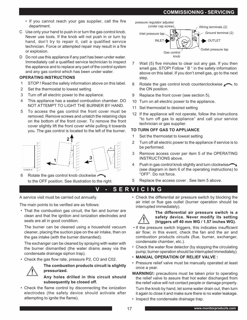
pressure regulator adjuster(under cap screw)
Inlet pressure tap
INLET
Gas controlknob
Wiring terminals (2)
Ground terminal (2)
Outlet pressure tap
OUTLET
COMMISSIONING - SERVICING
V - S E R V I C I N GA service visit must be carried out annually.
The main points to be verified are as follows:• That the combustion gas circuit, the fan and burner are
clean and that the ignition and ionization electrodes andseals are all in good condition.The burner can be cleaned using a household vacuumcleaner, placing the suction pipe on the air intake, then onthe gas intake (with the burner dismantled).The exchanger can be cleaned by spraying with water withthe burner dismantled (the water drains away via thecondensate drainage siphon trap).
• Check the gas flow rate, pressure P2, CO and C02.The combustion products circuit is slightlypressurized.Any holes drilled in this circuit shouldsubsequently be closed off.
• Check the flame control by disconnecting the ionizationelectrodes (the safety device should activate afterattempting to ignite the flame).
• Check the differential air pressure switch by blocking theair inlet or flue gas outlet (burner operation should beinterrupted immediately).
The differential air pressure switch is asafety device. Never modify its setting(triggers off 40 mm WG / 1.57 inches WG).
• If the pressure switch triggers, this indicates insufficientair flow; in this event, check the fan and the air andcombustion products circuits (flue, burner, exchanger,condensate chamber, etc.).
• Check the water flow detector (by stopping the circulatingpump; burner operation should be interrupted immediately).
• MANUAL OPERATION OF RELIEF VALVE :• Pressure relief valve must be manually operated at least
once a year.WARNING!: precautions must be taken prior to operating
the relief valve to assure that hot water discharged fromthe relief valve will not contact people or damage property.Turn the knob by hand, let some water drain out, then turnit again to close it and make sure there is no water leakage.
• Inspect the condensate drainage trap.

18MZ 25C/MZ 25S TECHNICAL INSTRUCTIONS
• In hard water areas, the domestic water exchanger shouldbe de-scaled regularly (carry out de-scaling as soon as areduction in the domestic hot water flow rate is observed).
• All moving parts have sealed, permanently lubricatedbearings. Therefore no periodic oiling is required.
• Flame visual check : the normal flame color is blue it couldbe slightly blue-orange during a few minutes just after aburner ignition. Yellow flame is not normal. In such a casestop the water heater and call your gas service company.
MZ 25 CV00.12731
A20.11061
V00.21225
L10.15083
L50.19250
X00.12734
L00.15086
/
L90.24635
/
C50.15504
1 - RECOMMENDED SERVICE PARTS
DESCRIPTIONControl panel
Viega condensate syphonic trap
Shell
Gas valve
Air pressure switch
Burner
Ignition transformer
DHW thermostat
Automatic air vent
DHW cylinder
Air fan
MZ 25 SV00.12731
A20.11061
V00.21225
L10.15083
L50.19250
X00.12734
L00.15086
L71.10492
L90.24635
V00.13874
C50.15504
PART NUMBER
These service parts can be ordered from your distributor, if you need information contact Monitor Products Inc. • (800) 524-1102
SERVICING - ASSEMBLY/DISMANTLING
DESCRIPTION3 way valve (body)
Circulating pump
Stainless steel filter
½ inch drain cock
High limit
Pressure relief valve
Water heating thermostat
Thermometer
On/ Off light switch
Winter/summer switch
Flow switch
Flue pipe
Control box
Control relay
Transformer
3 way valve motor
Flue high limit thermostat
Ignition electrode
Ionization probe
PART NUMBER
MZ 25 SL85.13803
L30.15074
U00.15093
K50.11590
L72.01023
L90.10548
L71.04202
L60.31042
C20.15505
C20.7949
L50.12534
N40.16810
L10.15253
C60.15500
C90.15411
L20.15499
L72.10273
L00.16672
L00.12950
MZ 25 CL85.13803
L30.15074
U00.15093
K50.11590
L72.01023
L90.10548
L71.04202
L60.31042
C20.15505
C20.7949
L50.12534
N40.16810
L10.15253
C60.15500
C90.15411
L20.15499
L72.10273
L00.16672
L00.12950
V I - A S S E M B L Y / D I S M A N T L I N G1 - COVERThe hot water generator cover is fixed at the bottom by a clipon system.Fig. 25
2 - ELECTRICAL CONNECTION UNITThe various electrical devices are all connected to the controlunit by special connectors which prevent any incorrectconnection after dismantling
Fig. 262 21
1CONNECTORS 1) Press snaps
2) Disconnect
A
B
CD
A: 20 mm = 0.8 inchesB: 2.25 mm = 0.09 inchesC: 10 mm = 0.4 inchesD: 4 mm = 0.16 inches
3 - BURNER
Electrode location
Fig. 27

19 www.monitorproducts.com
VII - DOMESTIC WATER HEATER
DOMESTIC WATER HEATER - WARRANTIES
Piping and components connected to the water heater for 1 - HEATER INCORPORATED INTO DUAL FUNCTION MODELthe space heating application shall be suitable for use with For the plumbing connection, refer to chapter III -potable water. INSTALLATION - section 5 - page 13.Toxic chemicals (such as those used for heating system The cold water supply has a control valve. Adjust thistreatment) must not be added to the potable water used for according to the water supply pressure so as to obtain a flowspace heating. rate of (2.91 gal/min / 11 l/mn); if possible, use the bath tap A water heater shall not be connected to any heating system as a reference.or component(s) previously used with a non-portable water Aim to obtain a hot water temperature of at least 113°F (45°C).heating appliance.
MONITOR PRODUCTS, INC.7A Marlen Drive, Robbinsville, NJ 08691
www.monitorproducts.comPHONE (609) 584-0505, FAX (609) 584-7629

20MZ 25C/MZ 25S TECHNICAL INSTRUCTIONS
As part of its policy of continuous product improvement, Monitor Products, Inc. reserves the right to make changeswithout notice COPYRIGHT © 2006 MONITOR PRODUCTS, INC.
First year-MPI warrants that each MZ Series Heating Systemssold by it to be free from defects in material and workmanship,under normal use and services, for a period of 1 year afterdate of purchase with an additional period of up to 3 months ifunit is not installed at the time of purchase.First through tenth year-MPI warrants that the primary heatexchanger assembly consisting of water-tube heat exchanger,water jacket and condensate collector is free from defects inmaterial and workmanship for 10 years from the date ofpurchase.MPI corrosion inhibitor must be used in every MZ series heatingsystem. Failure to use this inhibitor will void this warranty.
NOTE: We will not accept any MZ heat exchangers forwarranty consideration without an 8 ounce water samplefrom the system. This is required to test for the properinhibitors. No credit will be issued without a watersample.
STANDARD PROVISIONS, TERMS AND CONDITIONS THATARE COMMON TO ALL MPI INDIVIDUAL PRODUCTWARRANTIES:These warranties are subject to the condition that the MPIproduct(s) must have been installed in accordance withmanufacturer’s instructions. These warranties extend only tothe first retail purchaser of the products and only to a productthat has not been moved from its original installation site.These warranties do not apply to commercial applications.In addition to each product warranty listed, MPI warrantiesdo not cover:
1) Components that are part of the heating system butwere not furnished by MPI as part of the heating system.
2) The workmanship of any installer of MPI’s product(s).In addition, this warranty does not assume any liabilityof any nature for unsatisfactory performance causedby improper installation.
3) Any costs for labor for removal and reinstallation of thealleged defective part, the cost of shipping ortransportation to MPI and back to the consumer, ifnecessary, and any other materials necessary to performthe exchange.
4) Replacement parts beyond the balance of the originalwarranty period.
REMEDY: If within the applicable warranty period, any pro-duct(s) or part(s) included in this warranty proves to bedefective in material and/or workmanship, then MPI shall repairor replace, at its option, the defective product(s) or part(s) andreturn it to the consumer.
PROCEDURE FOR OBTAINING PERFORMANCE UNDERTHIS WARRANTY: In order to obtain performance under thiswarranty, the original purchaser must promptly (in no eventlater than thirty (30) days after discovery of the defect) see tothe return of the product(s) or part(s) in question, accompaniedby a properly filled out MPI warranty claim form (Availablefrom MPI by mail or phone). Any claim made under thiswarranty must be accompanied by proof of original purchasedate, sales invoice or cancelled check showing the serialnumber as satisfactory evidence. Any replacements are madesubject to validation by MPI of in-warranty coverage. An itemto be replaced must be made available in exchange for thereplacement.SOLE REMEDY: The remedy and liability for any breach ofwarranty, express or implied, set forth herein is the sole andexclusive remedy and the limit of liability for any such breach.EXCLUSIONS AND IMPLIED WARRANTIES: This warrantydoes not extend to any defect due to the negligence of others.Failure to install, operate or maintain the product(s) inaccordance with the installation, operation and maintenanceinstructions furnished with each new product, unreasonableuse, accidents, acts of god, fire, snow, floods, lightning,alteration, ordinary wear and tear, or the use of unauthorizedor non-standard parts.ALL IMPLIED WARRANTIES, IF ANY, ARISING UNDER LAWIN CONNECTION WITH THE SALES BY MPI OF ANYPRODUCT(S) ARE LIMITED IN EXTENT AND DURATIONTO THE DURATION OF THIS WRITTEN WARRANTY. THEREARE NO WARRANTIES, EXPRESS OR IMPLIED, OFMERCHANTABILITY, FITNESS FOR A PARTICULARPURPOSE OTHER THAN AS EXPRESSLY STATED HEREIN.MPI SHALL NOT BE RESPONSIBLE FOR ANY INCIDENTAL,INDIRECT, PUNITIVE, OR CONSEQUENTIAL DAMAGESWHETHER AS A RESULT OF BREACH OF WARRANTY,NEGLIGENCE, STRICT LIABILITY IN TORT OROTHERWISE.Note: Some jurisdictions do not allow: (a) limitations on howlong an implied warranty lasts; or (b) the exclusion or limitationof incidental, indirect, punitive or consequential damages, sothe above limitations or exclusions may not apply to you.NO VARIATION OF TERMS: the parties intend that thiswarranty be the exclusive and final expression of theiragreement.No person has the authority to orally, in writing or in any otherway vary the terms, conditions or exclusions of this warranty,or to make any express warranties other than those containedherein.LEGAL RIGHTS: This warranty gives you specific legal rightsand you may also have other rights which vary from jurisdictionto jurisdiction.
WARRANTIES
VIII - M O N I TO R P R O D U C T S , I N C . ( “ M P I ” ) L I M I T E D WA R R A N T I E S