Embed Size (px)
Citation preview
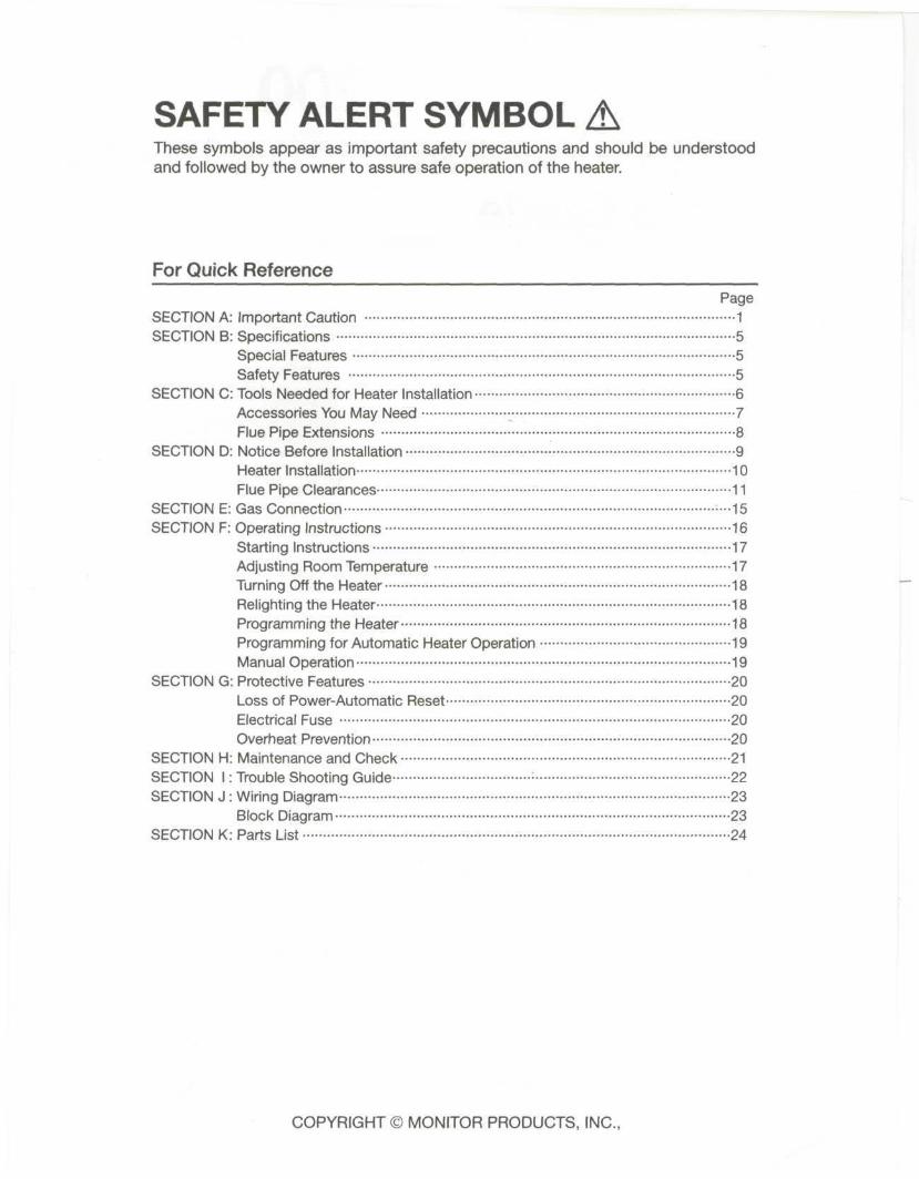
SAFETY ALERT SYMBOLThese symbols appear as important safety precautions and should be understoodand followed by the owner to assure safe operation of the heater.
For Quick ReferencePage
SECTION A: Important Caution 1SECTION B: Specifications 5
Special Features 5Safety Features 5
SECTION C: Tools Needed for Heater Installation 6Accessories You May Need • 7Flue Pipe Extensions 8
SECTION D: Notice Before Installation 9Heater Installation 10Flue Pipe Clearances 11
SECTION E: Gas Connection --15SECTION F: Operating Instructions 16
Starting Instructions 17Adjusting Room Temperature 17Turning Off the Heater 18Relighting the Heater 18Programming the Heater 18Programming for Automatic Heater Operation 19Manual Operation 19
SECTION G: Protective Features 20Loss of Power-Automatic Reset 20Electrical Fuse 20Overheat Prevention 20
SECTION H: Maintenance and Check 21SECTION I: Trouble Shooting Guide : 22SECTION J : Wiring Diagram • 23
Block Diagram 23SECTION K: Parts List 24
COPYRIGHT © MONITOR PRODUCTS, INC.,
SECTION A
IMPORTANT CAUTION
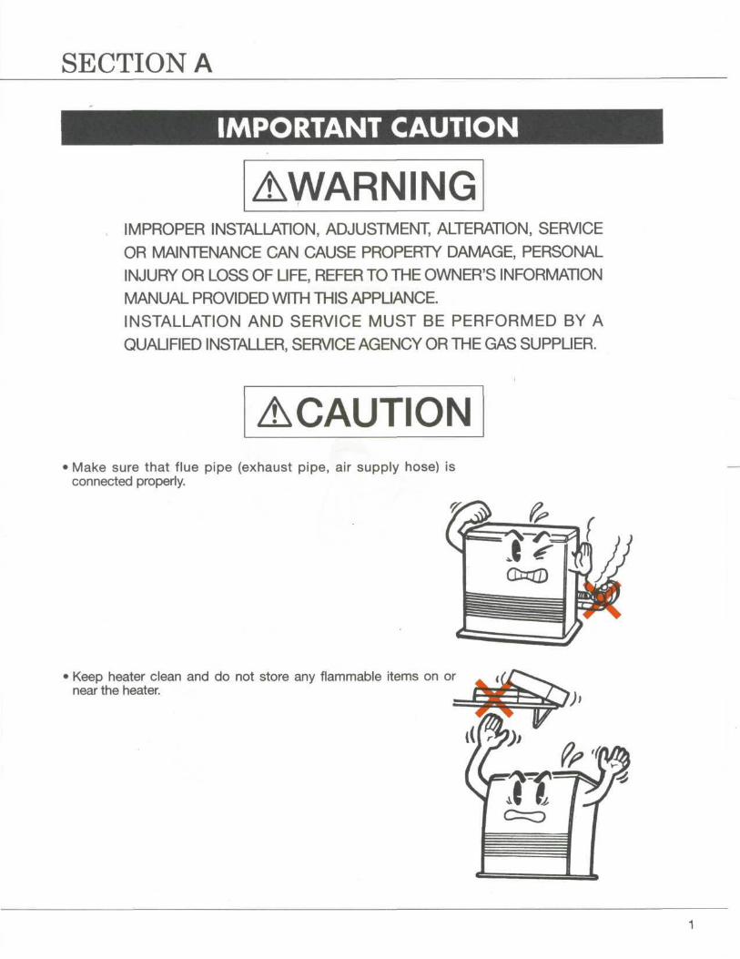
AWARNINGIMPROPER INSTALLATION, ADJUSTMENT, ALTERATION, SERVICE
OR MAINTENANCE CAN CAUSE PROPERTY DAMAGE, PERSONAL
INJURY OR LOSS OF LIFE, REFER TO THE OWNER'S INFORMATION
MANUAL PROVIDED WITH THIS APPLIANCE.
INSTALLATION AND SERVICE MUST BE PERFORMED BY A
QUALIFIED INSTALLER, SERVICE AGENCY OR THE GAS SUPPLIER.
ACAUTIONMake sure that flue pipe (exhaust pipe, air supply hose) isconnected properly.
Keep heater clean and do not store any flammable items on ornear the heater.
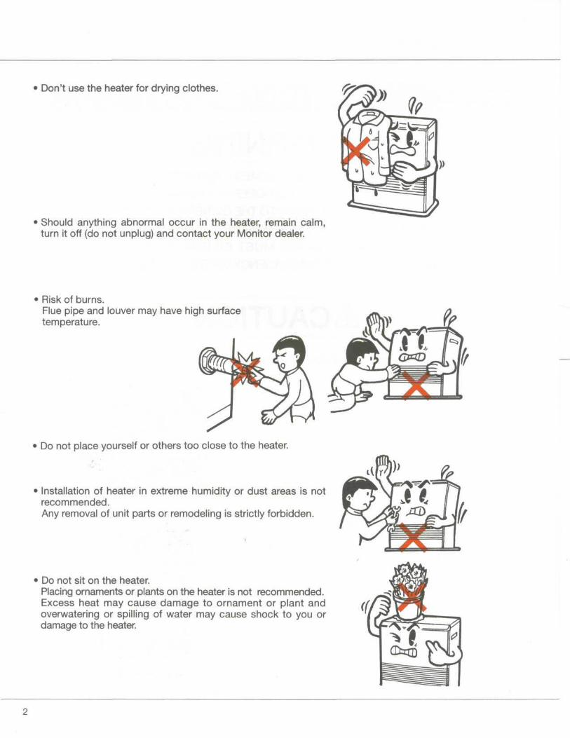
• Don't use the heater for drying clothes.
• Should anything abnormal occur in the heater, remain calm,turn it off (do not unplug) and contact your Monitor dealer.
• Risk of burns.Flue pipe and louver may have high surfacetemperature.
Do not place yourself or others too close to the heater.
Installation of heater in extreme humidity or dust areas is notrecommended.Any removal of unit parts or remodeling is strictly forbidden.
• Do not sit on the heater.Placing ornaments or plants on the heater is not recommended.Excess heat may cause damage to ornament or plant andoverwatering or spilling of water may cause shock to you ordamage to the heater.
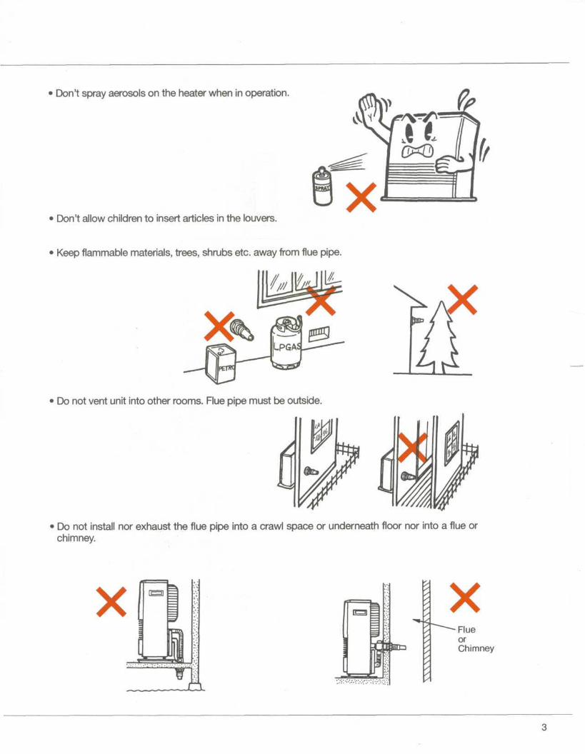
Don't spray aerosols on the heater when in operation.
Don't allow children to insert articles in the louvers.
Keep flammable materials, trees, shrubs etc. away from flue pipe.
Do not vent unit into other rooms. Flue pipe must be outside.
Do not install nor exhaust the flue pipe into a crawl space or underneath floor nor into a flue orchimney.
X
o
XFlueorChimney
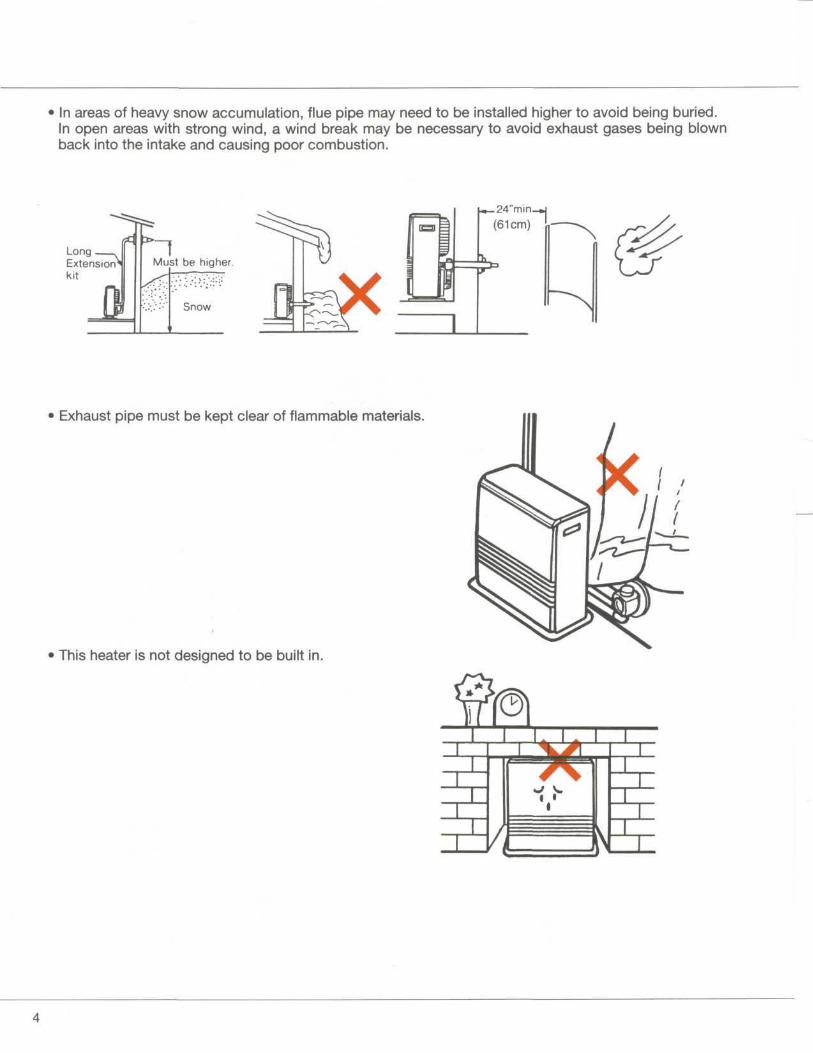
In areas of heavy snow accumulation, flue pipe may need to be installed higher to avoid being buried.In open areas with strong wind, a wind break may be necessary to avoid exhaust gases being blownback into the intake and causing poor combustion.
Long-—N
Extensionkit
*_24"min_»|(61cm) '-
Must be higher.
Snow
• Exhaust pipe must be kept clear of flammable materials.
This heater is not designed to be built in.
I I
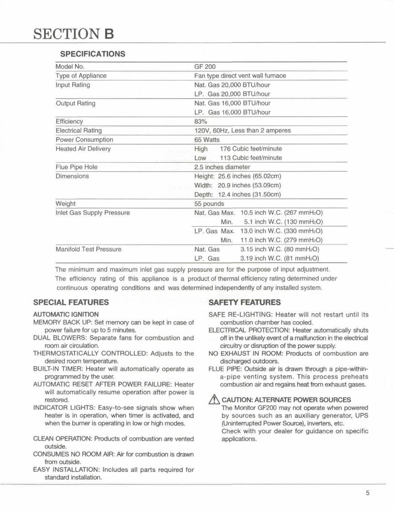
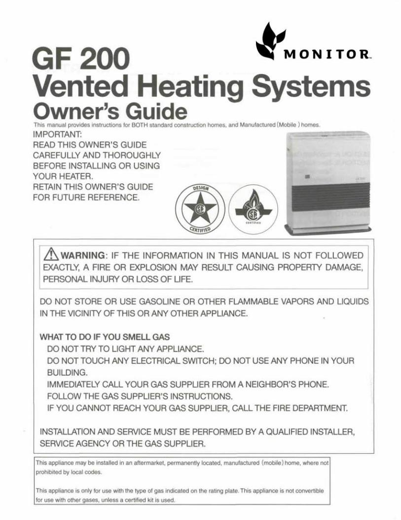
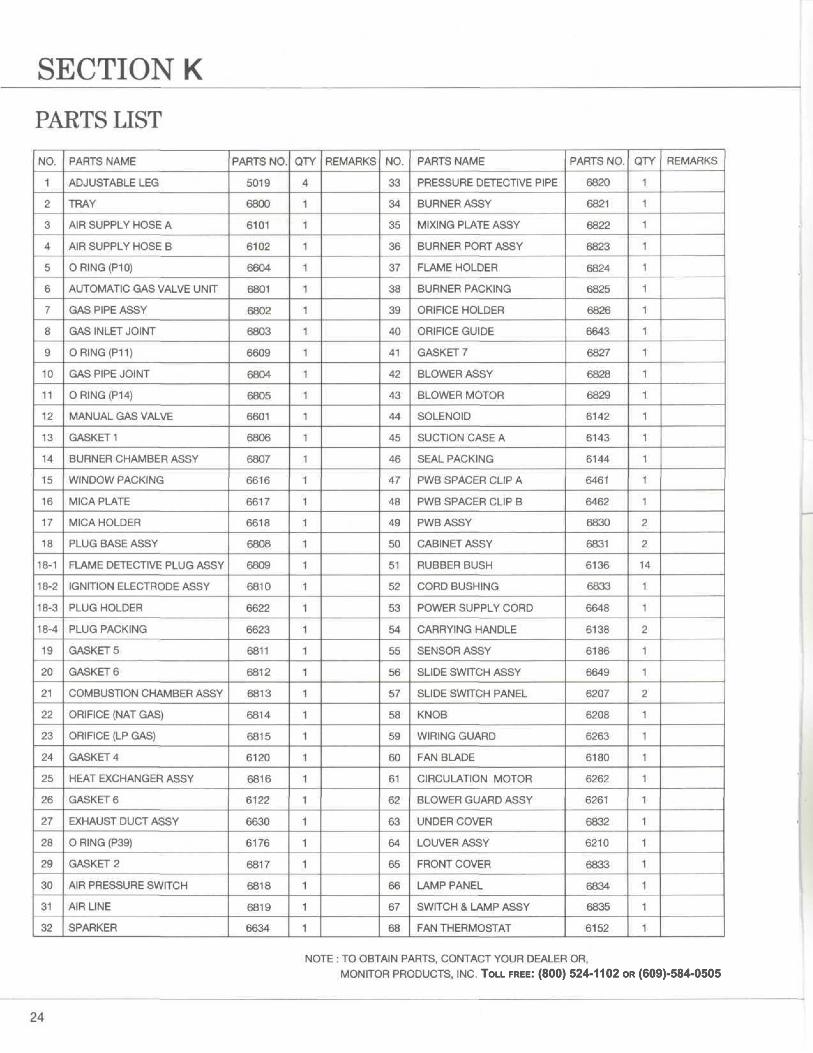
SECTION BSPECIFICATIONS
Model No. GF200Type of Appliance Fan type direct vent wall furnaceInput Rating Nat. Gas 20,000 BTU/hour
LP. Gas 20,000 BTU/hourOutput Rating Nat. Gas 16,000 BTU/hour
LP. Gas 16,000 BTU/hourEfficiencyElectrical RatingPower ConsumptionHeated Air Delivery
Flue Pipe HoleDimensions
83%120V, 60Hz, Less than 2 amperes65 WattsHigh 1 76 Cubic feet/minuteLow 1 1 3 Cubic feet/minute2.5 inches diameterHeight: 25.6 inches (65.02cm)Width: 20.9 inches (53.09cm)Depth: 12.4 inches (31.50cm)
Weight 55 poundsInlet Gas Supply Pressure Nat. Gas Max. 10.5 inch W.C. (267 mmH2O)
Min. 5.1 inch W.C. (130 mmH2O)LP. Gas Max. 13.0 inch W.C. (330 mmH2O)
Min. 11.0 inch W.C. (279 mmHzO)Manifold Test Pressure Nat. Gas 3.15 inch W.C. (80 mmH2O)
LP. Gas 3.19 inch W.C. (81 mmHsO)
The minimum and maximum inlet gas supply pressure are for the purpose of input adjustment.The efficiency rating of this appliance is a product of thermal efficiency rating determined undercontinuous operating conditions and was determined independently of any installed system.
SPECIAL FEATURES
AUTOMATIC IGNITIONMEMORY BACK UP: Set memory can be kept in case of
power failure for up to 5 minutes.DUAL BLOWERS: Separate fans for combustion and
room air circulation.THERMOSTATICALLY CONTROLLED: Adjusts to the
desired room temperature.BUILT-IN TIMER: Heater will automatically operate as
programmed by the user.AUTOMATIC RESET AFTER POWER FAILURE: Heater
will automatically resume operation after power isrestored.
INDICATOR LIGHTS: Easy-to-see signals show whenheater is in operation, when timer is activated, andwhen the burner is operating in low or high modes.
CLEAN OPERATION: Products of combustion are ventedoutside.
CONSUMES NO ROOM AIR: Air for combustion is drawnfrom outside.
EASY INSTALLATION: Includes all parts required forstandard installation.
SAFETY FEATURES
SAFE RE-LIGHTING: Heater will not restart until itscombustion chamber has cooled.
ELECTRICAL PROTECTION: Heater automatically shutsoff in the unlikely event of a malfunction in the electricalcircuitry or disruption of the power supply.
NO EXHAUST IN ROOM: Products of combustion aredischarged outdoors.
FLUE PIPE: Outside air is drawn through a pipe-within-a-pipe venting system. This process preheatscombustion air and regains heat from exhaust gases.
A CAUTION: ALTERNATE POWER SOURCESThe Monitor GF200 may not operate when poweredby sources such as an auxiliary generator, UPS(Uninterrupted Power Source), inverters, etc.Check with your dealer for guidance on specificapplications.
SECTION CBefore installing your heater, be sure to check and comply with local and state building and electrical codesthat may apply to vented heaters in your area. Permanent wiring must be installed by a licensed electrician.
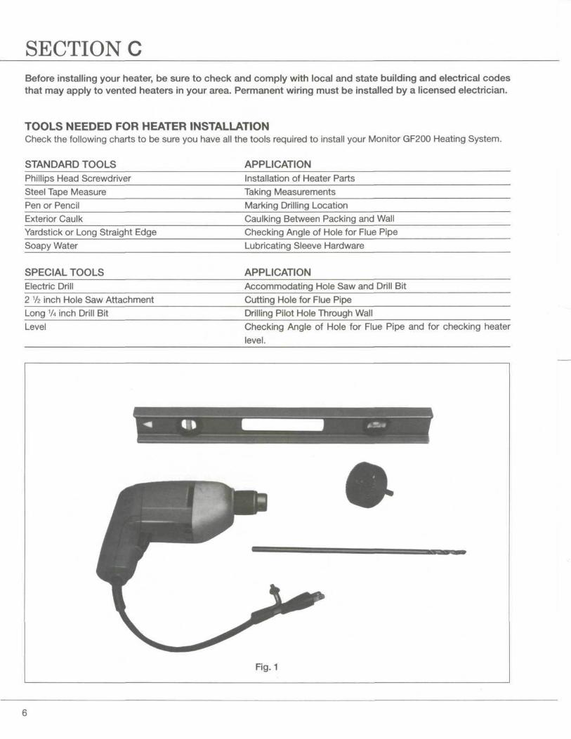
TOOLS NEEDED FOR HEATER INSTALLATIONCheck the following charts to be sure you have all the tools required to install your Monitor GF200 Heating System.
STANDARD TOOLS APPLICATIONPhillips Head Screwdriver Installation of Heater PartsSteel Tape Measure Taking MeasurementsPen or Pencil Marking Drilling LocationExterior Caulk Caulking Between Packing and WallYardstick or Long Straight Edge Checking Angle of Hole for Flue PipeSoapy Water Lubricating Sleeve Hardware
SPECIAL TOOLS APPLICATIONElectric Drill Accommodating Hole Saw and Drill Bit2 1/2 inch Hole Saw Attachment Cutting Hole for Flue PipeLong 1A inch Drill Bit Drilling Pilot Hole Through WallLevel Checking Angle of Hole for Flue Pipe and for checking heater
level.
Fig.1
ACCESSORIES YOU MAY NEEDCheck the list below and see your MPI dealer for accessories you may need or want for installation of your heatingsystem.
ACCESSORY APPLICATIONMedium Flue Pipe P/N 8206 For use where wall thickness is up to 141/2 inches (36.83cm)Long Flue Pipe P/N 8005 For use where wall thickness is up to 20Va inches (52.07cm)
Extra Short, Short, Medium or For use where "standard" installation is not practical.Long Extension Kit or Elbow Adapter kit
(See Flue Pipe Extensions, page 8)
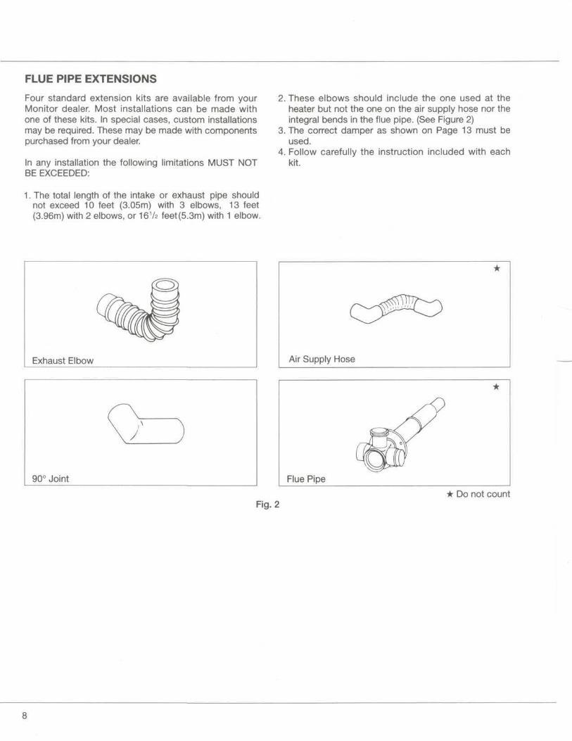
FLUE PIPE EXTENSIONS
Four standard extension kits are available from yourMonitor dealer. Most installations can be made withone of these kits. In special cases, custom installationsmay be required. These may be made with componentspurchased from your dealer.
In any installation the following limitations MUST NOTBE EXCEEDED:
1. The total length of the intake or exhaust pipe shouldnot exceed 10 feet (3.05m) with 3 elbows, 13 feet(3.96m) with 2 elbows, or 161/z feet (5.3m) with 1 elbow.
2. These elbows should include the one used at theheater but not the one on the air supply hose nor theintegral bends in the flue pipe. (See Figure 2)
3. The correct damper as shown on Page 13 must beused.
4. Follow carefully the instruction included with eachkit.
Exhaust Elbow
90° Joint
Air Supply Hose
Flue Pipe
* Do not countFig. 2
SECTION DNOTICE BEFORE INSTALLATIONThe heater must be installed by a qualified serviceperson according to this installation instruction .
The installation must conform with local codes or, in theabsence of local codes, the National fuel Gas Code,ANSI Z223.1 .
The installation must conform with local codes or, in theabsence of local codes, the current CAN 1-B149INSTALLATION CODE.
For mobile housing and recreational installation thecurrent Standard CSA Z 240.4 GAS EQUIPPEDRECREATIONAL VEHICLES AND MOBILE HOUSING.
A manufactured home (mobile home) installation mustconform with the Manufactured Home Constructionand Safety Standard, Title 24 CFR, Part 3280, or, whensuch a standard is not applicable, the Standard forManufactured Home installations, ANSI A 225.1/NFPA501A.
Due to high temperatures the appliance should belocated out of traffic and away from furniture anddraperies.
Children and adults should be alerted to the hazards ofhigh surface temperatures and should stay away toavoid burns or clothing ignition.
Young children should be carefully supervised whenthey are in the same room as the appliance.
Clothing or other flammable material should not beplaced on or near the appliance.
Make sure that the flow of combustion and ventilationair not be obstructed.
Any safety or guard removed for servicing an appliancemust be replaced prior to operating the appliance.
A WARNINGDo not operate appliance with the panel removed,cracked or broken. Replacement of the panel should bedone by a licensed or qualified service person.
Installation and repair should be done by a qualifiedservice person. The appliance should be inspectedbefore use and at least annually by a qualified serviceperson. More frequent cleaning may be required due toexcessive lint from carpeting, bedding material, etc. It isimperative that control compartments, burners andcirculating air passageways of the appliance be keptclean.
Do not use this heater if any part has been under water.Immediately call a qualified service technician to inspectthe heater and to replace any part of the control systemand any gas control which has been under water.
The appliance, when installed, must be electricallygrounded in accordance with local codes or, in theabsence of local codes, with the National ElectricalCode, ANSI/NFPA 70 .
The appliance, when installed, must be electricallyconnected and grounded in accordance with local codesor, in the absence of local codes, with the current CSAC22.1 CANADIAN ELECTRICAL CODE.
^WARNINGTHIS APPLIANCE IS EQUIPPED WITH A THREE-PRONG(GROUNDING) PLUG FOR YOUR PROTECTIONAGAINST SHOCK HAZARD AND SHOULD BEPLUGGED DIRECTLY INTO A PROPERLY GROUNDEDTHREE-PRONG RECEPTACLE. DO NOT CUT ORREMOVE THE GROUNDING PRONG FROM THIS PLUG.
IN MANUFACTURED/MOBILE HOMES WIRED FOR120/240V, ENSURE THAT THE GF200 IS ONLYPLUGGED INTO A 120 VOLT CIRCUIT.
A CAUTIONBefore converting the GF200 gas type (to Nat Gas orLiquid Propane), Read instructions in Section E, Page 15.
For manufactured home (mobile home) or residentialinstallation convertible for use with natural gas and liquefiedpetroleum gases when provision is made for the simpleconversion from one gas to the other.
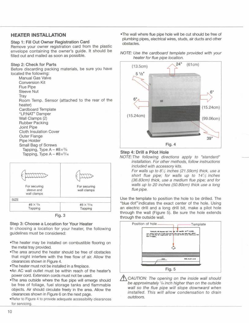
HEATER INSTALLATIONStep 1: Fill Out Owner Registration CardRemove your owner registration card from the plasticenvelope containing the owner's guide. It should befilled out and mailed as soon as possible.
Step 2: Check for PartsBefore discarding packing materials, be sure you havelocated the following:
Manual Gas ValveConversion KitFlue PipeSleeve NutTrayRoom Temp. Sensor (attached to the rear of theheater)Cardboard Template"LP.NAT" DamperWall Clamps (2)Rubber PackingJoint PipeCloth Insulation CoverOuter FlangePipe HolderSmall Bag of Screws
Tapping, Type A - #8x3ATapping, Type A - #8x5/ie
•The wall where flue pipe hole will be cut should be free ofplumbing pipes, electrical wires, studs, air ducts and otherobstacles.
NOTE: Use the cardboard template provided with yourheater for flue pipe location.
24" (61cm)
(15.24cm)
Fig. 4
For securingsleeve andwall clamps
For securingwall clamps
SIZE#8 X 3/4Tapping
#8 X 5/16
Tapping
Fig. 3
Step 3: Choose a Location for Your HeaterIn choosing a location for your heater, the followingguidelines must be considered:
•The heater may be installed on combustible flooring onthe metal tray provided.
•The area around the heater should be free of obstaclesthat might interfere with the free flow of air. Allow theclearances shown in Figure 4.
•The heater must not be installed in a fireplace.•An AC wall outlet must be within reach of the heater'spower cord. Extension cords must not be used.
•The area outside where the flue pipe will emerge shouldbe free of foliage, fuel storage tanks and flammableobjects. Air should circulate freely in the area. Allow theclearances shown in Figure 6 on the next page.
•Refer to Figure 4 to provide adequate accessibility clearancesfor servicing.
Step 4: Drill a Pilot HoleNOTE:The following directions apply to "standard"
installation. For other methods, follow instructionsincluded with accessory kits.For walls up to 81/2 inches (21.59cm) thick, use ashort flue pipe; for walls up to 141/£ inches(36.83cm) thick, use a medium flue pipe; and forwalls up to 20 inches (50.80cm) thick use a longflue pipe.
Use the template to position the hole to be drilled. The"blue dot" indicates the exact center of the hole. Usingan electric drill and a long drill bit, make a pilot holethrough the wall (Figure 5). Be sure the hole extendsthrough the outside wall.
Position of hole Template
Fig. 5
^CAUTION: The opening on the inside wall shouldbe approximately 1/4 inch higher than on the outsidewall so the flue pipe will slope downward wheninstalled. This will allow condensation to drainoutdoors.
10
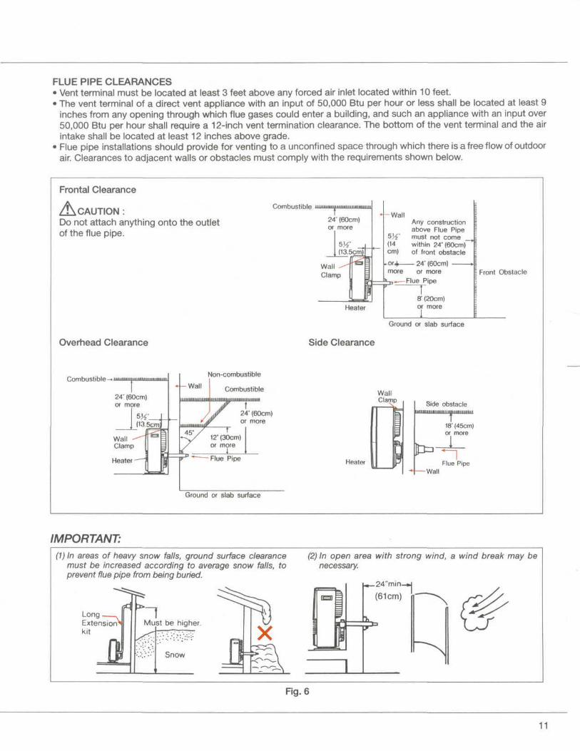
FLUE PIPE CLEARANCES• Vent terminal must be located at least 3 feet above any forced air inlet located within 10 feet.• The vent terminal of a direct vent appliance with an input of 50,000 Btu per hour or less shall be located at least 9
inches from any opening through which flue gases could enter a building, and such an appliance with an input over50,000 Btu per hour shall require a 12-inch vent termination clearance. The bottom of the vent terminal and the airintake shall be located at least 12 inches above grade.
• Flue pipe installations should provide for venting to a unconfined space through which there is a free flow of outdoorair. Clearances to adjacent walls or obstacles must comply with the requirements shown below.
Frontal Clearance
A CAUTION :Do not attach anything onto the outletof the flue pipe.
Combustible luuuuuuWall
Any constructionabove Flue Pipemust not comewithin 24" (60cm)of front obstacle
or4 24" (60cm) -more or more
Flue Pipe
Overhead Clearance
Combustible-.™
Heater
Side Clearance
ff (20cm)or more
Front Obstacle
Ground or slab surface
Non-combustible
CombustibleWallClamp
Heater
Side obstacle
Ground or slab surface
IMPORTANT:(1) In areas of heavy snow falls, ground surface clearance
must be increased according to average snow falls, toprevent flue pipe from being buried.
Must be higher.LongExtensionkit
(2) In open area with strong wind, a wind break may benecessary.
»_24"min_»|
(61cm)
Fig. 6
11
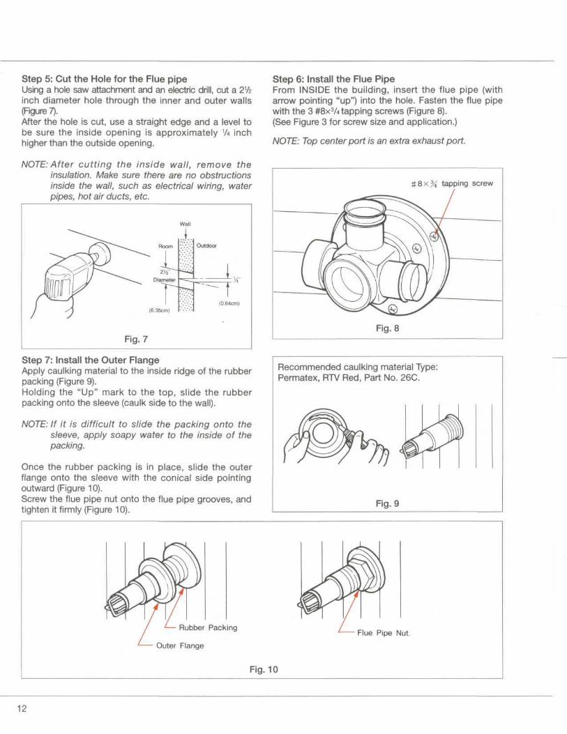
Step 5: Cut the Hole for the Flue pipeUsing a hole saw attachment and an electric drill, cut a 21/2inch diameter hole through the inner and outer walls(Figure 7).After the hole is cut, use a straight edge and a level tobe sure the inside opening is approximately 1A inchhigher than the outside opening.
NOTE: After cutting the inside wall, remove theinsulation. Make sure there are no obstructionsinside the wall, such as electrical wiring, waterpipes, hot air ducts, etc.
Wall
(0.64cm)
Fig. 7
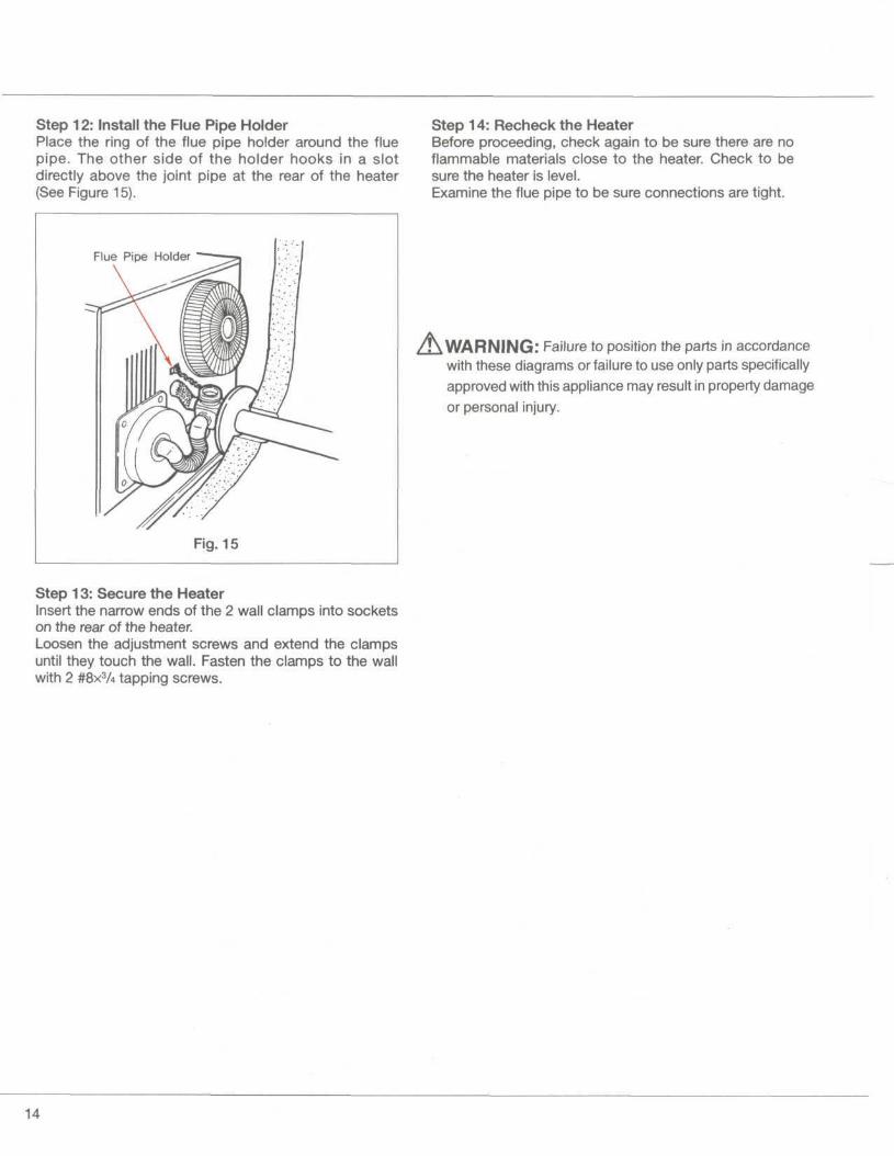
Step 7: Install the Outer FlangeApply caulking material to the inside ridge of the rubberpacking (Figure 9).Holding the "Up" mark to the top, slide the rubberpacking onto the sleeve (caulk side to the wall).
NOTE: If it is difficult to slide the packing onto thesleeve, apply soapy water to the inside of thepacking.
Once the rubber packing is in place, slide the outerflange onto the sleeve with the conical side pointingoutward (Figure 10).Screw the flue pipe nut onto the flue pipe grooves, andtighten it firmly (Figure 10).
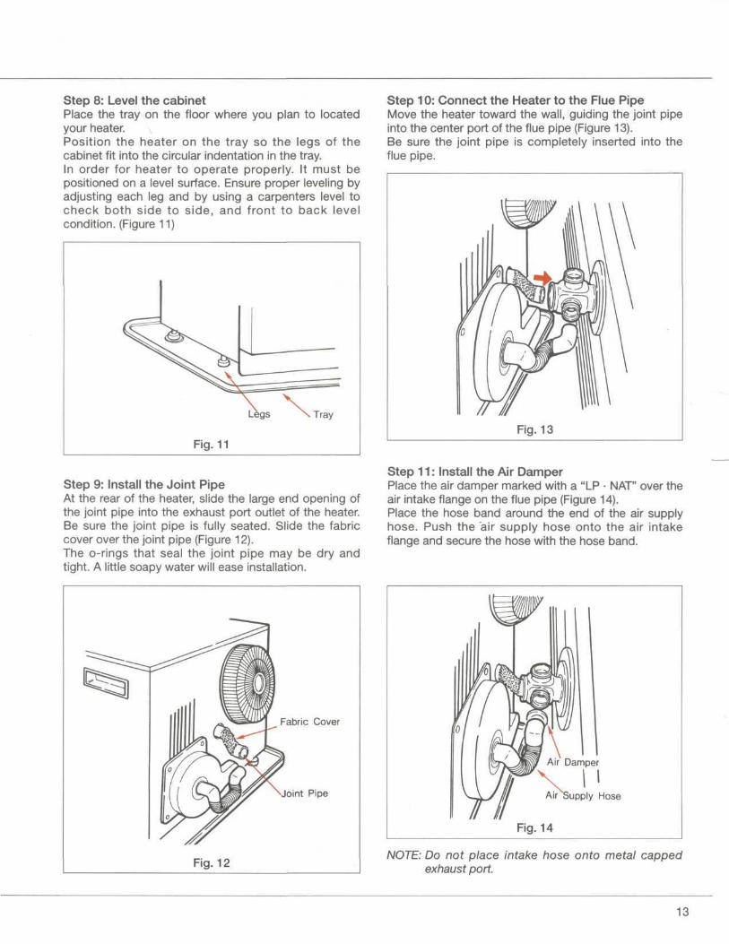
Step 6: Install the Flue PipeFrom INSIDE the building, insert the flue pipe (witharrow pointing "up") into the hole. Fasten the flue pipewith the 3 #8x3A tapping screws (Figure 8).(See Figure 3 for screw size and application.)
NOTE: Top center port is an extra exhaust port.
tapping screw
Fig. 8
Recommended caulking material Type:Permatex, RTV Red, Part No. 26C.
Fig. 9
Rubber Packing
Outer Flange
Flue Pipe Nut.
Fig. 10
12
Step 8: Level the cabinetPlace the tray on the floor where you plan to locatedyour heater.Position the heater on the tray so the legs of thecabinet fit into the circular indentation in the tray.In order for heater to operate properly. It must bepositioned on a level surface. Ensure proper leveling byadjusting each leg and by using a carpenters level tocheck both side to side, and front to back levelcondition. (Figure 11)
Step 10: Connect the Heater to the Flue PipeMove the heater toward the wall, guiding the joint pipeinto the center port of the flue pipe (Figure 13).Be sure the joint pipe is completely inserted into theflue pipe.
Tray
Fig. 11Fig. 13
Step 9: Install the Joint PipeAt the rear of the heater, slide the large end opening ofthe joint pipe into the exhaust port outlet of the heater.Be sure the joint pipe is fully seated. Slide the fabriccover over the joint pipe (Figure 12).The o-rings that seal the joint pipe may be dry andtight. A little soapy water will ease installation.
Step 11: Install the Air DamperPlace the air damper marked with a "LP • NAT" over theair intake flange on the flue pipe (Figure 14).Place the hose band around the end of the air supplyhose. Push the air supply hose onto the air intakeflange and secure the hose with the hose band.
Fabric Cover
•Joint Pipe Air Supply Hose
Fig. 14
NOTE: Do not place intake hose onto metal cappedexhaust port.
13
Step 12: Install the Flue Pipe HolderPlace the ring of the flue pipe holder around the fluepipe. The other side of the holder hooks in a slotdirectly above the joint pipe at the rear of the heater(See Figure 15).
Step 14: Recheck the HeaterBefore proceeding, check again to be sure there are noflammable materials close to the heater. Check to besure the heater is level.Examine the flue pipe to be sure connections are tight.
Flue Pipe Holder
Fig. 15
/!\ WARNING: Failure to position the parts in accordancewith these diagrams or failure to use only parts specificallyapproved with this appliance may result in property damageor personal injury.
Step 13: Secure the HeaterInsert the narrow ends of the 2 wall clamps into socketson the rear of the heater.Loosen the adjustment screws and extend the clampsuntil they touch the wall. Fasten the clamps to the wallwith 2 #8x3A tapping screws.
14
SECTION EGAS CONNECTIONI.The gas supply line shall be gas-tight, sized and so
installed as to provide a supply of gas sufficient tomeet the maximum demand of the heater without lossof pressure.
2. A shut off valve should be installed in the upstream ofthe gas line to permit servicing.
3. Flexible pipe and any appliance connector valve usedfor gas piping shall be types approved by nationallyrecognized agencies.
4. Any compound used on the threaded joint of the gaspiping shall be a type which resists the action ofliquefied petroleum gas.
5. Supplied gas pressure must be within the limits shownin the specifications.
6. After completion of gas pipe connections, all jointsincluding at the heater must be checked for gas-tightness by means of leak detector solution, soapand water, or an equivalent nonflammable solution, asapplicable.CAUTION: Since some leak test solutions, includingsoap and water, may cause corrosion or stresscracking, the piping shall be rinsed with water aftertesting, unless it has been determined that the leaktest solution is noncorrosive.
7. The appliance and its appliance main gas valve must bedisconnected from the gas supply piping system duringany pressure testing of that system at test pressures inexcess of 1/2 psi (3.5kPa).The appliance must be isolated from the gas pipingsystem by closing its equipment shutoff valve duringany pressure testing of the gas supply piping systemat test pressure equal to or less than 1/2 psi(3.5kPa).
8. A 1/8" test plug is provided for testing of manifoldpressure see schematic for location (page 26)At time of installation installer must supply a 1/8"N.P.T. plugged tapping, accessible for test gaugeconnection, immediately upstream of the gas supplyconnection of the appliance.
9. The minimum and maximum inlet gas supply pressureare for the purpose of input adjustment.
GAS CONVERSIONConversion should only be performed by a qualifiedMonitor GF service technician.The conversion shall be carried out in accordance withthe requirements of the provincial authorities havingjurisdiction and in accordance with the requirements ofthe CAN 1-B149.1 and .2 installation code.CAREFULLY FOLLOW THE COMPLETECONVERSION INSTRUCTIONS CONTAINED IN THECONVERSION KIT SUPPLIED WITH THE GF200.
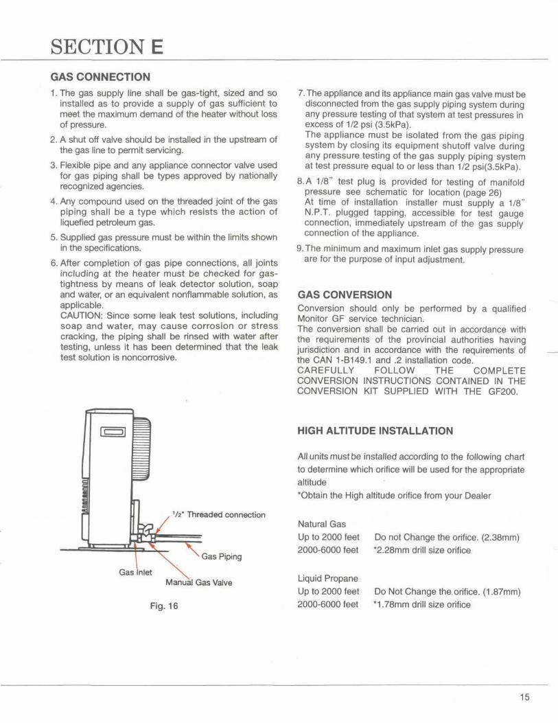
Gas Inlet
Vz" Threaded connection
Gas Piping
Manual Gas Valve
HIGH ALTITUDE INSTALLATION
All units must be installed according to the following chartto determine which orifice will be used for the appropriatealtitude"Obtain the High altitude orifice from your Dealer
Fig. 16
Natural GasUp to 2000 feet2000-6000 feet
Liquid PropaneUp to 2000 feet2000-6000 feet
Do not Change the orifice. (2.38mm)*2.28mm drill size orifice
Do Not Change the orifice. (1.87mm)*1.78mm drill size orifice
15
SECTION F
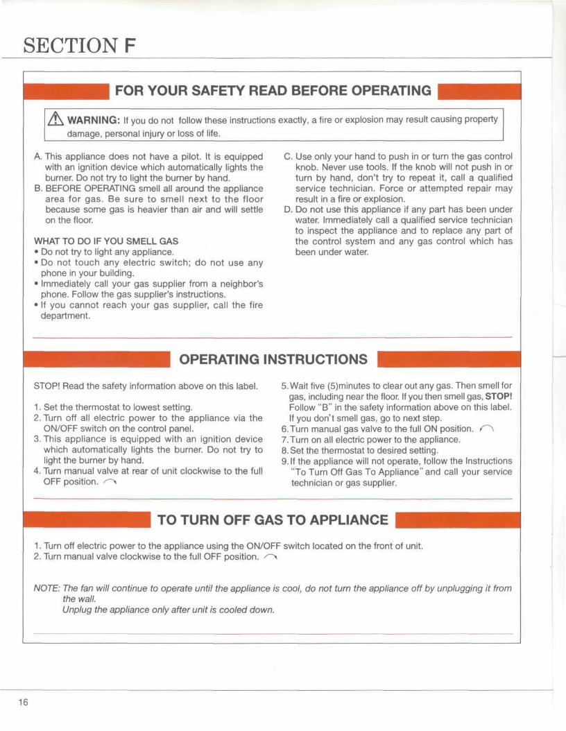
FOR YOUR SAFETY READ BEFORE OPERATING
WARNING: If you do not follow these instructions exactly, a fire or explosion may result causing propertydamage, personal injury or loss of life.
A. This appliance does not have a pilot. It is equippedwith an ignition device which automatically lights theburner. Do not try to light the burner by hand.
B. BEFORE OPERATING smell all around the appliancearea for gas. Be sure to smell next to the floorbecause some gas is heavier than air and will settleon the floor.
WHAT TO DO IF YOU SMELL GAS• Do not try to light any appliance.• Do not touch any electric switch; do not use any
phone in your building.• Immediately call your gas supplier from a neighbor's
phone. Follow the gas supplier's instructions.• If you cannot reach your gas supplier, call the fire
department.
C. Use only your hand to push in or turn the gas controlknob. Never use tools. If the knob will not push in orturn by hand, don't try to repeat it, call a qualifiedservice technician. Force or attempted repair mayresult in a fire or explosion.
D. Do not use this appliance if any part has been underwater. Immediately call a qualified service technicianto inspect the appliance and to replace any part ofthe control system and any gas control which hasbeen under water.
OPERATING INSTRUCTIONS
STOP! Read the safety information above on this label.
1. Set the thermostat to lowest setting.2. Turn off all electric power to the appliance via the
ON/OFF switch on the control panel.3. This appliance is equipped with an ignition device
which automatically lights the burner. Do not try tolight the burner by hand.
4. Turn manual valve at rear of unit clockwise to the fullOFF position. /">
5. Wait five (S)minutes to clear out any gas. Then smell forgas, including near the floor. If you then smell gas, STOP!Follow "B" in the safety information above on this label.If you don't smell gas, go to next step.
6.Turn manual gas valve to the full ON position. O\7. Turn on all electric power to the appliance.8. Set the thermostat to desired setting.9. If the appliance will not operate, follow the Instructions
"To Turn Off Gas To Appliance" and call your servicetechnician or gas supplier.
TO TURN OFF GAS TO APPLIANCE
1. Turn off electric power to the appliance using the ON/OFF switch located on the front of unit.2. Turn manual valve clockwise to the full OFF position. ^~>
NOTE: The fan will continue to operate until the appliance is cool, do not turn the appliance off by unplugging it fromthe wall.Unplug the appliance only after unit is cooled down.
16
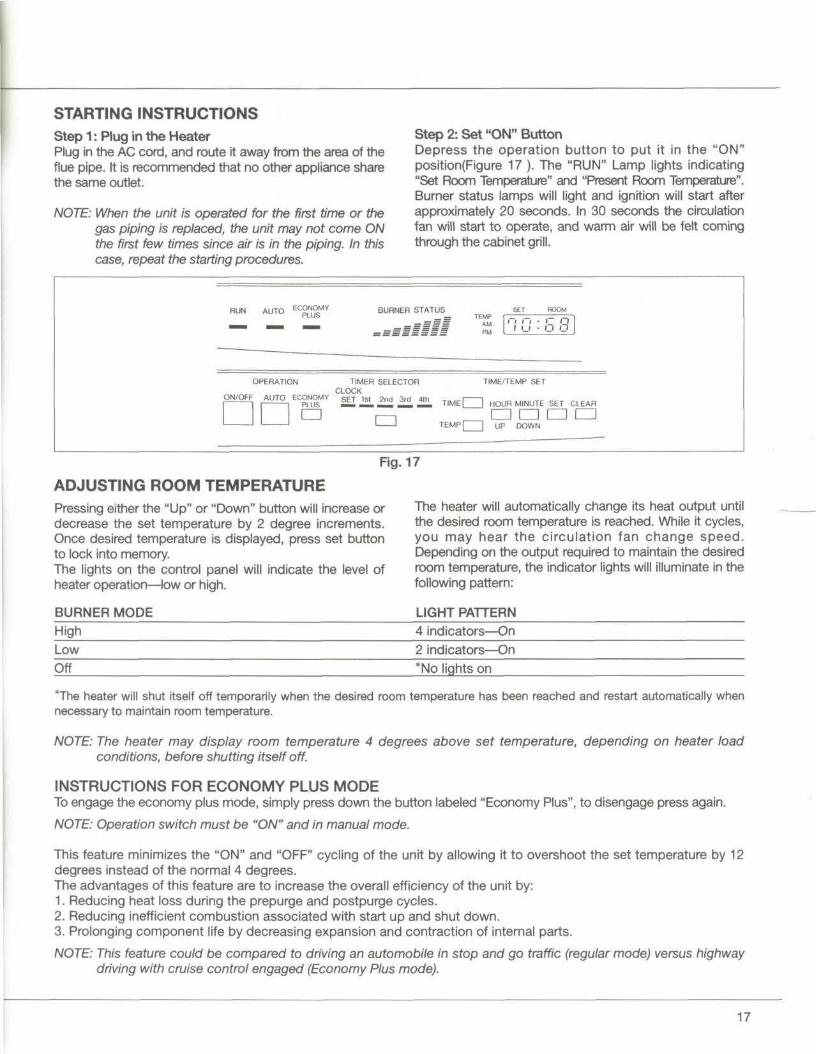
STARTING INSTRUCTIONSStep 1: Plug in the HeaterPlug in the AC cord, and route it away from the area of theflue pipe. It is recommended that no other appliance sharethe same outlet.
NOTE: When the unit is operated for the first time or thegas piping is replaced, the unit may not come ONthe first few times since air is in the piping. In thiscase, repeat the starting procedures.
Step 2: Set "ON" ButtonDepress the operation button to put it in the "ON"position(Figure 17 ). The "RUN" Lamp lights indicating"Set Room Temperature" and "Present Room Temperature".Burner status lamps will light and ignition will start afterapproximately 20 seconds. In 30 seconds the circulationfan will start to operate, and warm air will be felt conningthrough the cabinet grill.
RUN AUTO EC°LN°S
MY BURNER STATUSTEMP
AM
I'M
- n - i- ni i_i - n O
ON/OFF
OPERATION TIMER SELECTORCLOCK
AUTO ECONOMY SET ,st 2nd 3rd 41
TIME/TEMP SET
TIMEC H HOUR MINUTE SET CLEAR
n cn a cTEMP| | UP DOWN
Fig. 17
ADJUSTING ROOM TEMPERATUREPressing either the "Up" or "Down" button will increase ordecrease the set temperature by 2 degree increments.Once desired temperature is displayed, press set buttonto lock into memory.The lights on the control panel will indicate the level ofheater operation—low or high.
BURNER MODE
The heater will automatically change its heat output untilthe desired room temperature is reached. While it cycles,you may hear the circulation fan change speed.Depending on the output required to maintain the desiredroom temperature, the indicator lights will illuminate in thefollowing pattern:
LIGHT PATTERNHigh 4 indicators—OnLow 2 indicators—OnOff *No lights on
*The heater will shut itself off temporarily when the desired room temperature has been reached and restart automatically whennecessary to maintain room temperature.
NOTE: The heater may display room temperature 4 degrees above set temperature, depending on heater loadconditions, before shutting itself off.
INSTRUCTIONS FOR ECONOMY PLUS MODETo engage the economy plus mode, simply press down the button labeled "Economy Plus", to disengage press again.
NOTE: Operation switch must be "ON" and in manual mode.
This feature minimizes the "ON" and "OFF" cycling of the unit by allowing it to overshoot the set temperature by 12degrees instead of the normal 4 degrees.The advantages of this feature are to increase the overall efficiency of the unit by:1. Reducing heat loss during the prepurge and postpurge cycles.2. Reducing inefficient combustion associated with start up and shut down.3. Prolonging component life by decreasing expansion and contraction of internal parts.
NOTE: This feature could be compared to driving an automobile in stop and go traffic (regular mode) versus highwaydriving with cruise control engaged (Economy Plus mode).
17
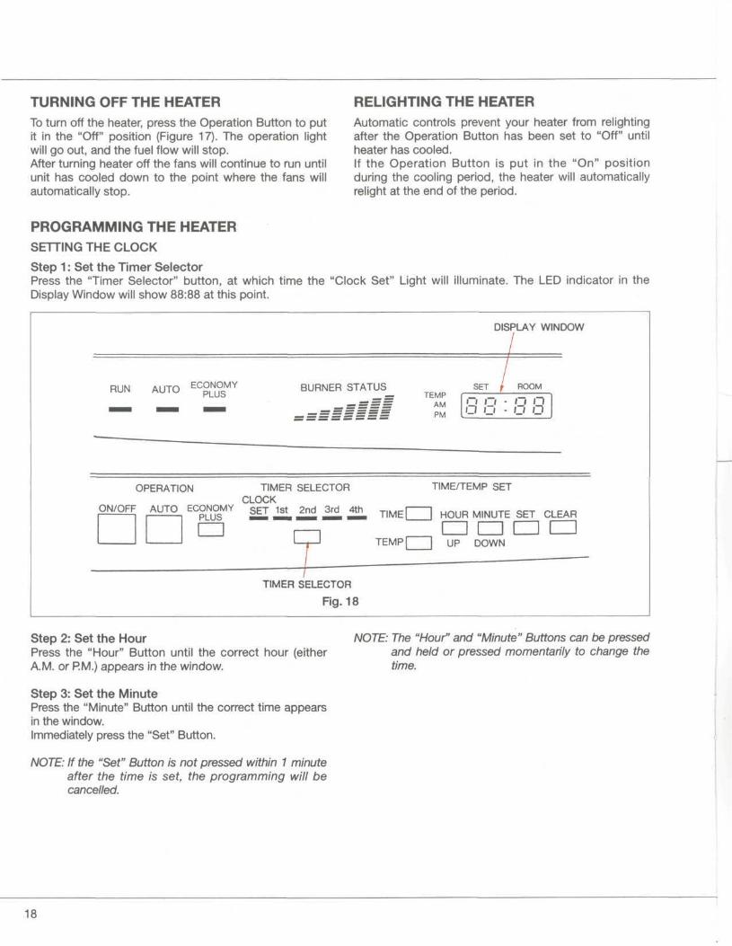
TURNING OFF THE HEATERTo turn off the heater, press the Operation Button to putit in the "Off" position (Figure 17). The operation lightwill go out, and the fuel flow will stop.After turning heater off the fans will continue to run untilunit has cooled down to the point where the fans willautomatically stop.
RELIGHTING THE HEATERAutomatic controls prevent your heater from relightingafter the Operation Button has been set to "Off" untilheater has cooled.If the Operation Button is put in the "On" positionduring the cooling period, the heater will automaticallyrelight at the end of the period.
PROGRAMMING THE HEATERSETTING THE CLOCK
Step 1: Set the Timer SelectorPress the "Timer Selector" button, at which time the "Clock Set" Light will illuminate. The LED indicator in theDisplay Window will show 88:88 at this point.
DISPLAY WINDOW
RUN AUTO BURNER STATUSTEMP
AMPM
SET ROOM
8 3 : 8 3
OPERATION TIMER SELECTORCLOCK
ON/OFF AUTO ECONOMY SET 1st 2nd 3rd 4
TIME/TEMP SET
HOUR MINUTE SET CLEAR
I I I I I I I ITEMP| | UP DOWN
TIMER SELECTOR
Fig. 18
Step 2: Set the HourPress the "Hour" Button until the correct hour (eitherA.M. or P.M.) appears in the window.
Step 3: Set the MinutePress the "Minute" Button until the correct time appearsin the window.Immediately press the "Set" Button.
NOTE: If the "Set" Button is not pressed within 1 minuteafter the time is set, the programming will becancelled.
NOTE: The "Hour" and "Minute" Buttons can be pressedand held or pressed momentarily to change thetime.
18
PROGRAMMING FOR AUTOMATIC HEATER OPERATION
The Monitor GF200 Heating System is capable of providingup to 4 different temperature settings for 4 different timesof the day. Not all 4 settings have to be used; 2, 3 or 4settings can be used. A clear understanding ofprogramming temperatures and time from the previouspages is needed before programming the automaticsettings. Also, the present time must have been set.
Step 1: Setting the 1 st Time/TemperaturePressing the Timer Selector Button will illuminate theTime/Temp Light.Press the "Time" Button. Set the 1st desired time bypressing the "Hour" and "Minute" Buttons as describedunder, "Setting the Clock". Once the desired time "AM orPM" is displayed, press the "Set" Button to lock intomemory.Press the "Temp" button. Set the desired temperature forthe 1st time setting by using the "Up" and "Down"Buttons. Once the desired temp is displayed, press the"Set" Button to lock into memory.
Example: 1 st Time / TempSAM 60°
Step 2: Setting the 2nd Time/TemperaturePress the Tinner Selector Button again and the 2ndTime/Temp Light will illuminate.Follow same steps as above, except for 2nd time/temp.(ie; 2nd 5PM 74 Degrees)Repeat if a 3rd or 4th setting is desired.
Typical Example of a 4-time/temp selection:TIME TEMP
1st SAM 60°2nd 5PM 74°3rd 11PM 70°4th 5:30AM 76°
Step 3: Activate Automatic OperationFor the heater to operate on automatic once the settingsare in memory, simply press the "Auto" Button on thecontrol panel. The "Auto" Light will illuminate to confirm theheater is in the automatic operation mode. The heater willnow maintain the programmed temp for that time of day.
IMPORTANT: The heater will not operate in automaticunless the On/Off switch is in the "On"position.
Step 4: Clearing An Automatic SettingIf you wish to clear any automatic setting, press the TimerSelector Button to the appropriate setting and press the"Clear" button. A new setting will need to be enteredotherwise the old setting will return after 30 seconds.
MANUAL OPERATIONTo deactivate the automatic operation, simply press the"Auto" Button. The "Auto" Light will no longer beilluminated and the heater will run on a manual setting. Thissetting will be determined by the previous auto setting forthat time of day, unless reset. The automatic settings willremain in memory even if the unit is running in manual,unless there is a power outage for more than 5 minutes.
19
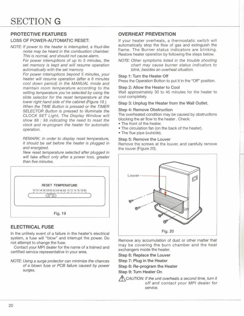
SECTION GPROTECTIVE FEATURESLOSS OF POWER-AUTOMATIC RESET:NOTE: If power to the heater is interrupted, a thud-like
noise may be heard in the combustion chamber.This is normal, and should not cause alarm.For power interruptions of up to 5 minutes, theset memory is kept and will resume operationautomatically with the set memory.For power interruptions beyond 5 minutes, yourheater will resume operation (after a 6 minutescool down period) in the MANUAL mode andmaintain room temperature according to thesetting temperature you've selected by using theslide selector for the reset temperature at thelower right hand side of the cabinet (Figure 19).When the TIME Button is pressed or the TIMERSELECTOR Button is pressed to illuminate theCLOCK SET Light, The Display Window willshow 88 : 88 indicating the need to reset theclock and re-program the heater for automaticoperation.
REMARK: In order to display reset temperature,it should be set before the heater is plugged inand energized.New reset temperature selected after plugged inwill take effect only after a power loss, greaterthan five minutes.
RESET TEMPERATURE
50 52 54 56 58 60 62 64 66 68 70 72 74 76 78 80
'era
Fig. 19
ELECTRICAL FUSEIn the unlikely event of a failure in the heater's electricalsystem, a fuse will "blow" and interrupt the power. Donot attempt to change the fuse.
Contact your MPI dealer for the name of a trained andcertified service representative in your area.
NOTE: Using a surge protector can minimize the chancesof a blown fuse or PCB failure caused by powersurges.
OVERHEAT PREVENTIONIf your heater overheats, a thermostatic switch willautomatically stop the flow of gas and extinguish theflame. The Burner status indicators are blinking.Restore heater operation by following the steps below.
NOTE: Other symptoms listed in the trouble shootingchart may cause burner status indicators toblink, besides an overheat situation.
Step 1: Turn the Heater OffPress the Operation Button to put it in the "Off" position.
Step 2: Allow the Heater to CoolWait approximately 30 to 45 minutes for the heater tocool completely.
Step 3: Unplug the Heater from the Wall Outlet.
Step 4: Remove ObstructionThe overheated condition may be caused by obstructionsblocking the air flow to the heater. Check:• The front of the heater.• The circulation fan (on the back of the heater).• The flue pipe (outside).
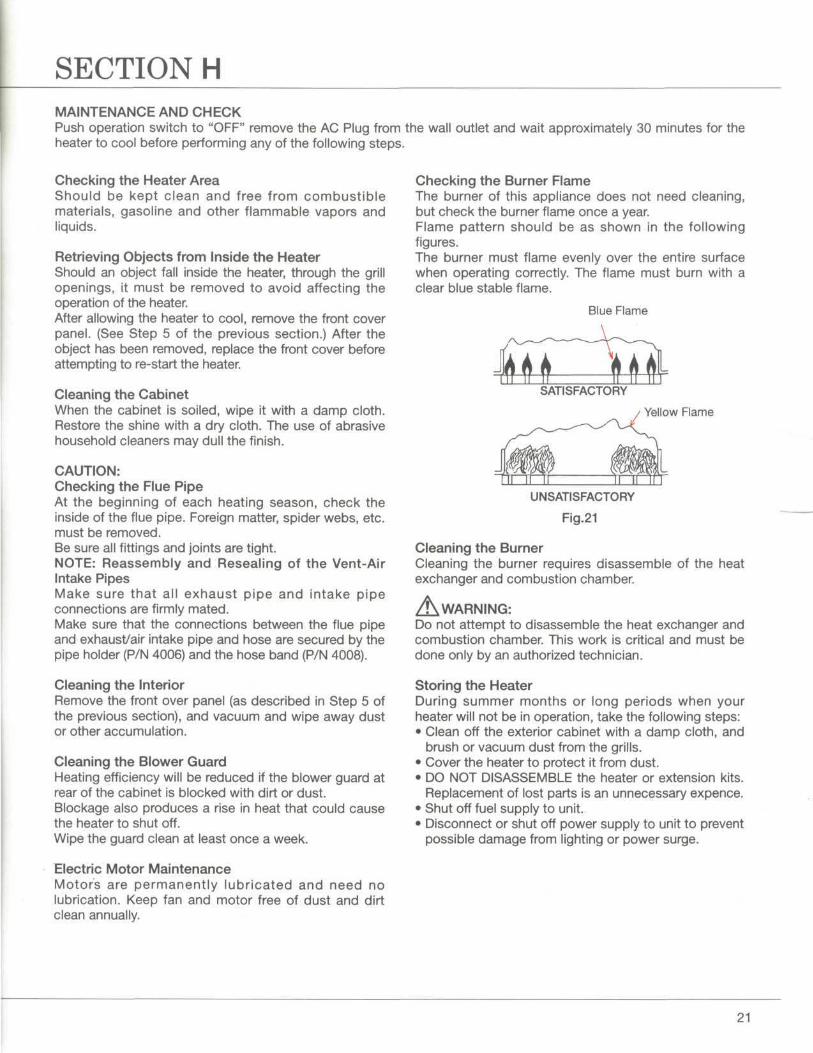
Step 5: Remove the LouverRemove the screws at the louver, and carefully removethe louver (Figure 20).
Louver
Fig. 20
Remove any accumulation of dust or other matter thatmay be covering the burn chamber and the heatexchangers inside the heater.Step 6: Replace the LouverStep 7: Plug in the HeaterStep 8: Re-program the HeaterStep 9: Turn Heater On
fi\CAUTION: If the unit overheats a second time, turn itoff and contact your MPI dealer forservice.
20
SECTION HMAINTENANCE AND CHECKPush operation switch to "OFF" remove the AC Plug from the wall outlet and wait approximately 30 minutes for theheater to cool before performing any of the following steps.
Checking the Heater AreaShould be kept clean and free from combustiblematerials, gasoline and other flammable vapors andliquids.
Retrieving Objects from Inside the HeaterShould an object fall inside the heater, through the grillopenings, it must be removed to avoid affecting theoperation of the heater.After allowing the heater to cool, remove the front coverpanel. (See Step 5 of the previous section.) After theobject has been removed, replace the front cover beforeattempting to re-start the heater.
Cleaning the CabinetWhen the cabinet is soiled, wipe it with a damp cloth.Restore the shine with a dry cloth. The use of abrasivehousehold cleaners may dull the finish.
CAUTION:Checking the Flue PipeAt the beginning of each heating season, check theinside of the flue pipe. Foreign matter, spider webs, etc.must be removed.Be sure all fittings and joints are tight.NOTE: Reassembly and Reseating of the Vent-AirIntake PipesMake sure that all exhaust pipe and intake pipeconnections are firmly mated.Make sure that the connections between the flue pipeand exhaust/air intake pipe and hose are secured by thepipe holder (P/N 4006) and the hose band (P/N 4008).
Cleaning the InteriorRemove the front over panel (as described in Step 5 ofthe previous section), and vacuum and wipe away dustor other accumulation.
Cleaning the Blower GuardHeating efficiency will be reduced if the blower guard atrear of the cabinet is blocked with dirt or dust.Blockage also produces a rise in heat that could causethe heater to shut off.Wipe the guard clean at least once a week.
Electric Motor MaintenanceMotors are permanently lubricated and need nolubrication. Keep fan and motor free of dust and dirtclean annually.
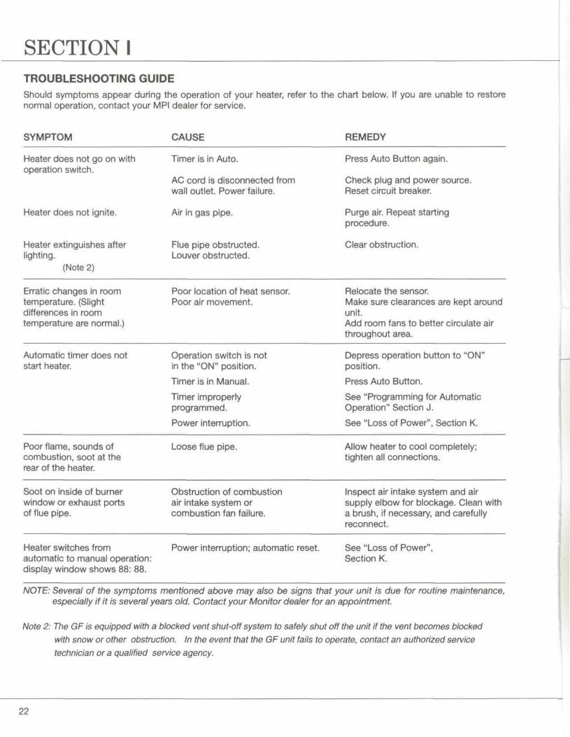
Checking the Burner FlameThe burner of this appliance does not need cleaning,but check the burner flame once a year.Flame pattern should be as shown in the followingfigures.The burner must flame evenly over the entire surfacewhen operating correctly. The flame must burn with aclear blue stable flame.
Blue Flame
SATISFACTORY
Yellow Flame
UNSATISFACTORY
Fig.21
Cleaning the BurnerCleaning the burner requires disassemble of the heatexchanger and combustion chamber.
A\ WARNING:Do not attempt to disassemble the heat exchanger andcombustion chamber. This work is critical and must bedone only by an authorized technician.
Storing the HeaterDuring summer months or long periods when yourheater will not be in operation, take the following steps:• Clean off the exterior cabinet with a damp cloth, and
brush or vacuum dust from the grills.• Cover the heater to protect it from dust.• DO NOT DISASSEMBLE the heater or extension kits.
Replacement of lost parts is an unnecessary expence.• Shut off fuel supply to unit.• Disconnect or shut off power supply to unit to prevent
possible damage from lighting or power surge.
21
SECTION ITROUBLESHOOTING GUIDEShould symptoms appear during the operation of your heater, refer to the chart below. If you are unable to restorenormal operation, contact your MPI dealer for service.
SYMPTOM CAUSE REMEDY
Heater does not go on withoperation switch.
Heater does not ignite.
Heater extinguishes afterlighting.
(Note 2)
Timer is in Auto.
AC cord is disconnected fromwall outlet. Power failure.
Air in gas pipe.
Flue pipe obstructed.Louver obstructed.
Press Auto Button again.
Check plug and power source.Reset circuit breaker.
Purge air. Repeat startingprocedure.
Clear obstruction.
Erratic changes in roomtemperature. (Slightdifferences in roomtemperature are normal.)
Poor location of heat sensor.Poor air movement.
Relocate the sensor.Make sure clearances are kept aroundunit.Add room fans to better circulate airthroughout area.
Automatic tinner does notstart heater.
Operation switch is notin the "ON" position.
Timer is in Manual.
Tinner improperlyprogrammed.
Power interruption.
Depress operation button to "ON"position.
Press Auto Button.
See "Programming for AutomaticOperation" Section J.
See "Loss of Power", Section K.
Poor flame, sounds ofcombustion, soot at therear of the heater.
Loose flue pipe. Allow heater to cool completely;tighten all connections.
Soot on inside of burnerwindow or exhaust portsof flue pipe.
Obstruction of combustionair intake system orcombustion fan failure.
Inspect air intake system and airsupply elbow for blockage. Clean witha brush, if necessary, and carefullyreconnect.
Heater switches fromautomatic to manual operation:display window shows 88: 88.
Power interruption; automatic reset. See "Loss of Power",Section K.
NOTE: Several of the symptoms mentioned above may also be signs that your unit is due for routine maintenance,especially if it is several years old. Contact your Monitor dealer for an appointment.
Note 2: The GF is equipped with a blocked vent shut-off system to safely shut off the unit if the vent becomes blockedwith snow or other obstruction. In the event that the GF unit fails to operate, contact an authorized servicetechnician or a qualified service agency.
22
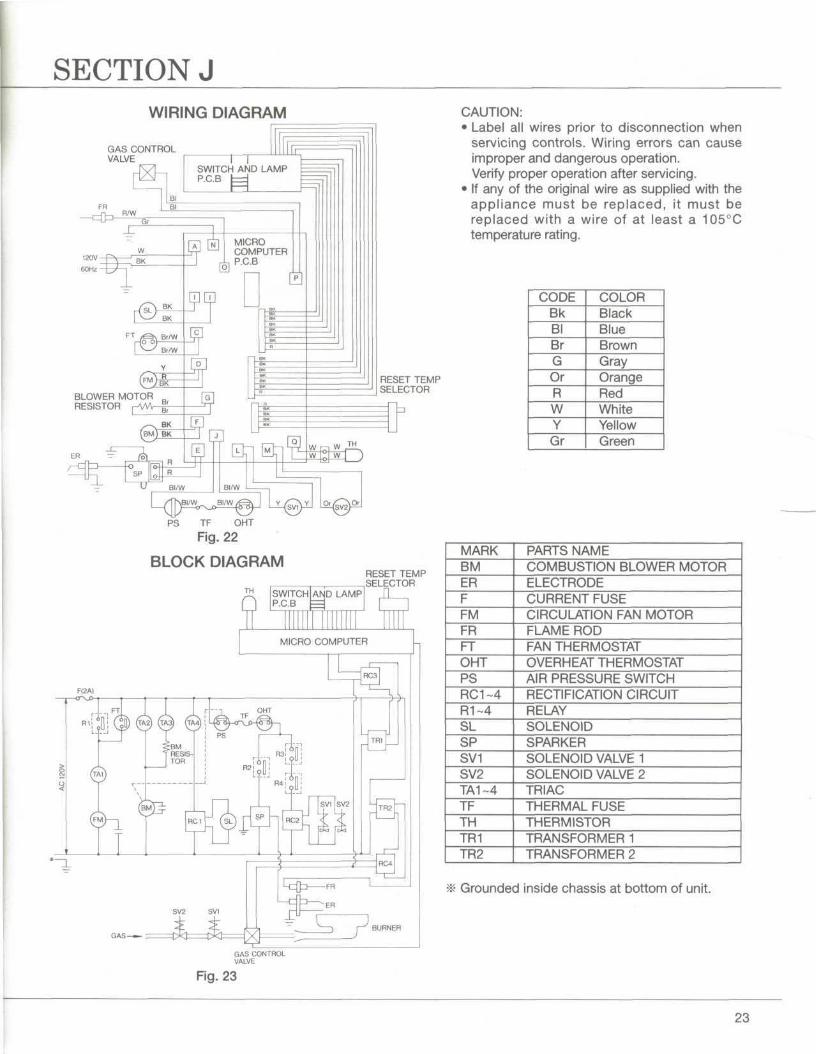
SECTION JWIRING DIAGRAM
GAS CONTROLVALVE
RESET TEMPSELECTOR
PS TF OHT
Fig. 22
BLOCK DIAGRAMRESET TEMPSELECTOR
HAS
GAS CONTROLVALVE
CAUTION:• Label all wires prior to disconnection when
servicing controls. Wiring errors can causeimproper and dangerous operation.Verify proper operation after servicing.
• If any of the original wire as supplied with theappliance must be replaced, it must bereplaced with a wire of at least a 105°Ctemperature rating.
CODEBkBlBrGOrRWYGr
COLORBlackBlueBrownGrayOrangeRedWhiteYellowGreen
MARKBMERFFMFRFTOHTPSRC1-4R1~4SLSPSV1SV2TA1-4TFTHTR1TR2
PARTS NAMECOMBUSTION BLOWER MOTORELECTRODECURRENT FUSECIRCULATION FAN MOTORFLAME RODFAN THERMOSTATOVERHEAT THERMOSTATAIR PRESSURE SWITCHRECTIFICATION CIRCUITRELAYSOLENOIDSPARKERSOLENOID VALVE 1SOLENOID VALVE 2TRIACTHERMAL FUSETHERMISTORTRANSFORMER 1TRANSFORMER 2
Grounded inside chassis at bottom of unit.
Fig. 23
23
TOLL FREE: (800) 524-1102 OR (609)-584-0505
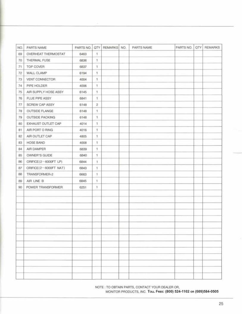
TOLL FREE: (800) 524-1102 OR (609)584-0505
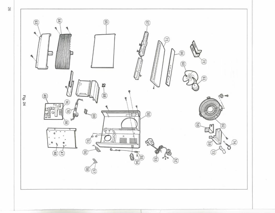
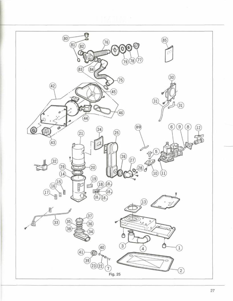
Fig. 25
27