Embed Size (px)
Citation preview
Sean Biggs 2012 MSC UK USER CONFERENCE Slide 1
Using MSC Adams to understand Automatic Transmission Torque Converter Damper
Performance
Sean BiggsPowertrain CAE Technical Specialist
JLR
MSC UK USER CONFERENCE 2012
Sean Biggs 2012 MSC UK USER CONFERENCE Slide 2
• What is a Automatic Transmission Torque Converter Damper?
• Why is a Torque Converter Damper needed?
• Adams Model Details
• Damper Configuration Study
• A Performance Analysis of 3 Damper Configurations
• Conclusions
Agenda
Sean Biggs 2012 MSC UK USER CONFERENCE Slide 3
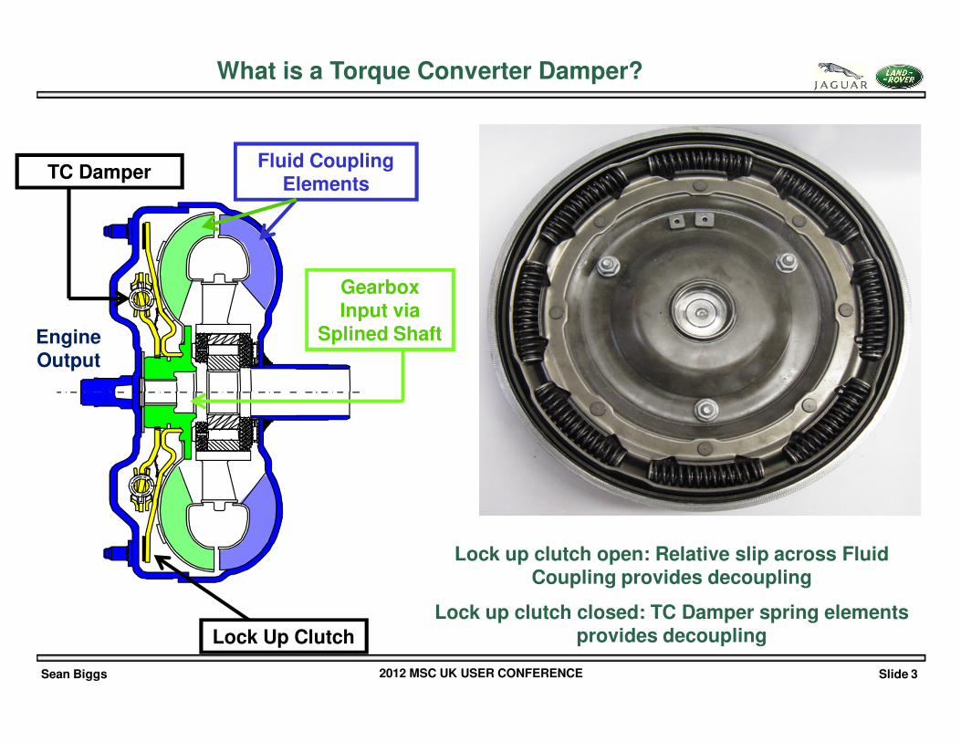
Lock Up Clutch
Gearbox Input via
Splined ShaftEngine Output
Fluid Coupling Elements
TC Damper
Lock up clutch open: Relative slip across Fluid Coupling provides decoupling
Lock up clutch closed: TC Damper spring elements provides decoupling
What is a Torque Converter Damper?
Sean Biggs 2012 MSC UK USER CONFERENCE Slide 4
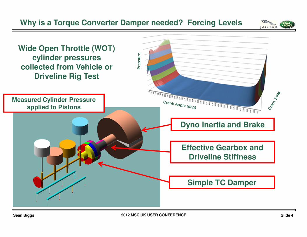
Simple TC Damper
Effective Gearbox and Driveline Stiffness
Dyno Inertia and Brake
Measured Cylinder Pressure applied to Pistons
Pre
ssu
re
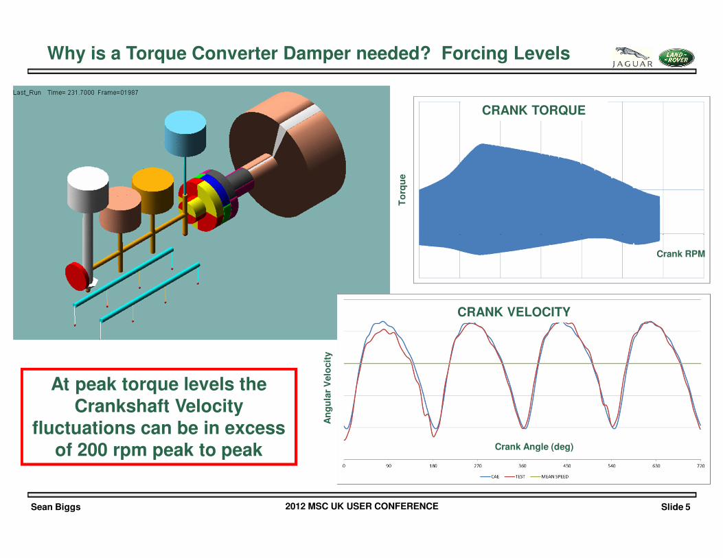
Why is a Torque Converter Damper needed? Forcing Levels
Wide Open Throttle (WOT) cylinder pressures
collected from Vehicle or Driveline Rig Test
Sean Biggs 2012 MSC UK USER CONFERENCE Slide 5
Crank Angle (deg)
An
gu
lar
Velo
cit
y
CRANK VELOCITY
CRANK TORQUE
Crank RPM
To
rqu
e
At peak torque levels the Crankshaft Velocity
fluctuations can be in excess of 200 rpm peak to peak
Why is a Torque Converter Damper needed? Forcing Levels
Sean Biggs 2012 MSC UK USER CONFERENCE Slide 6
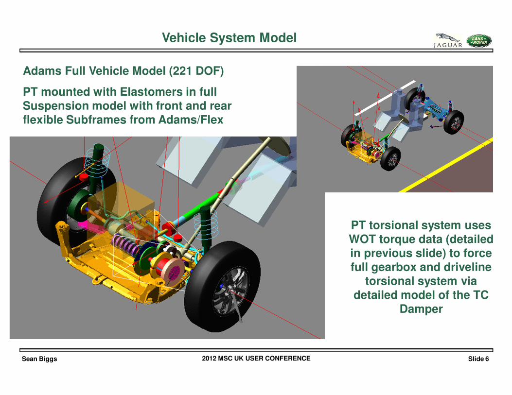
Vehicle System Model
Adams Full Vehicle Model (221 DOF)
PT mounted with Elastomers in full Suspension model with front and rear flexible Subframes from Adams/Flex
PT torsional system uses WOT torque data (detailed in previous slide) to force full gearbox and driveline
torsional system via detailed model of the TC
Damper
Sean Biggs 2012 MSC UK USER CONFERENCE Slide 7
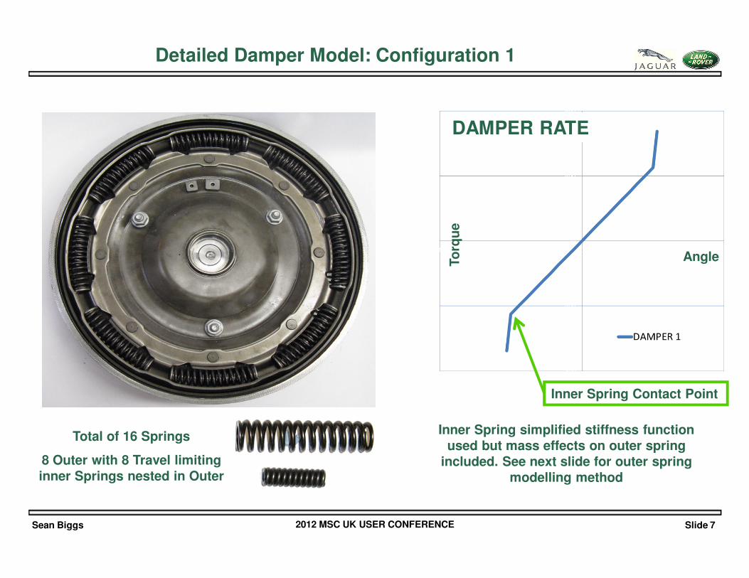
Total of 16 Springs
8 Outer with 8 Travel limiting inner Springs nested in Outer
Detailed Damper Model: Configuration 1
DAMPER RATE
AngleTo
rqu
e
Inner Spring Contact Point
Inner Spring simplified stiffness function used but mass effects on outer spring
included. See next slide for outer spring modelling method
Sean Biggs 2012 MSC UK USER CONFERENCE Slide 8
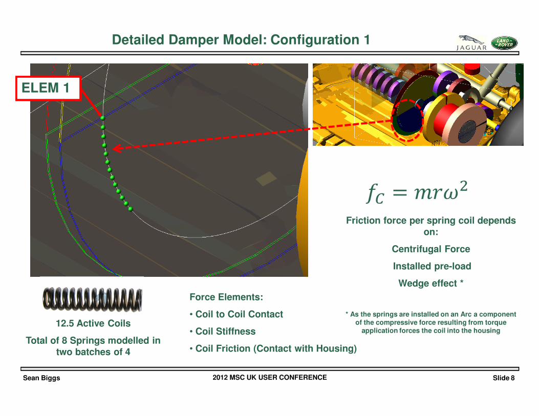
12.5 Active Coils
Total of 8 Springs modelled in two batches of 4
ELEM 1
Force Elements:
• Coil to Coil Contact
• Coil Stiffness
• Coil Friction (Contact with Housing)
Detailed Damper Model: Configuration 1
Friction force per spring coil depends on:
Centrifugal Force
Installed pre-load
Wedge effect *
* As the springs are installed on an Arc a component of the compressive force resulting from torque
application forces the coil into the housing
Sean Biggs 2012 MSC UK USER CONFERENCE Slide 9
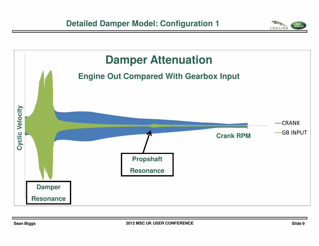
Detailed Damper Model: Configuration 1
Damper Attenuation
Engine Out Compared With Gearbox Input
Crank RPM
Cyc
lic V
elo
cit
y
Propshaft
Resonance
Damper
Resonance
Sean Biggs 2012 MSC UK USER CONFERENCE Slide 10
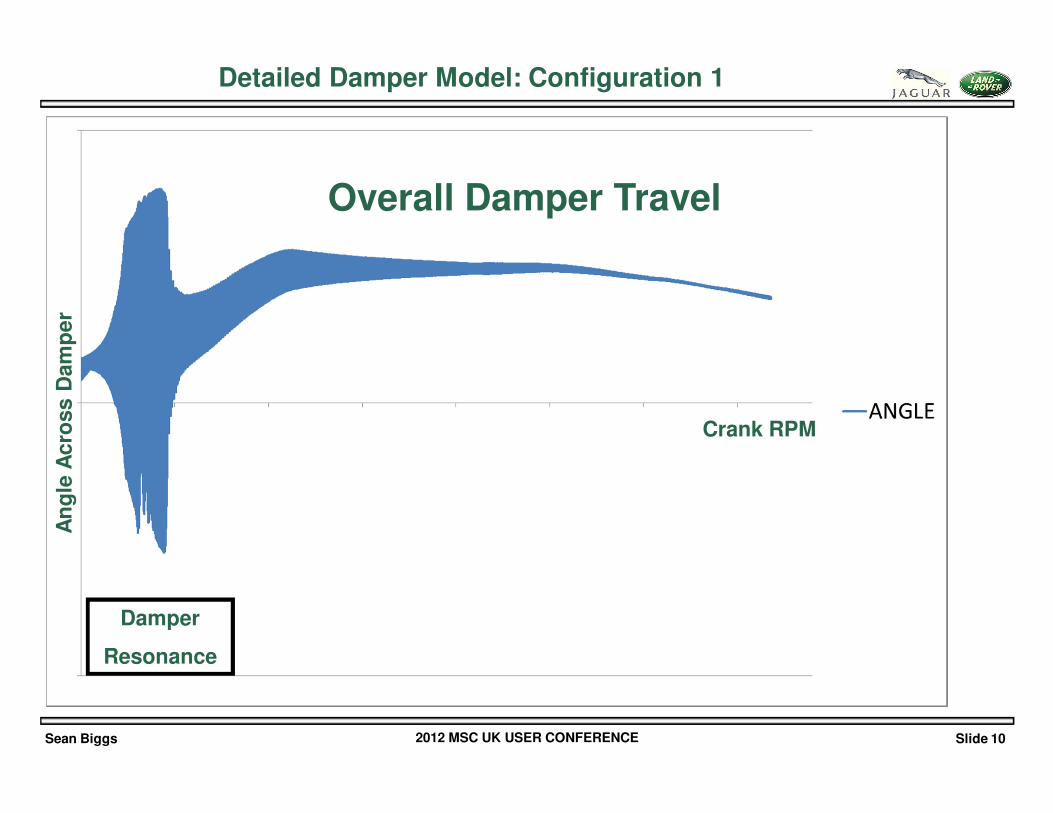
Detailed Damper Model: Configuration 1
Overall Damper Travel
Crank RPM
An
gle
Acro
ss D
am
per
Damper
Resonance
Sean Biggs 2012 MSC UK USER CONFERENCE Slide 11
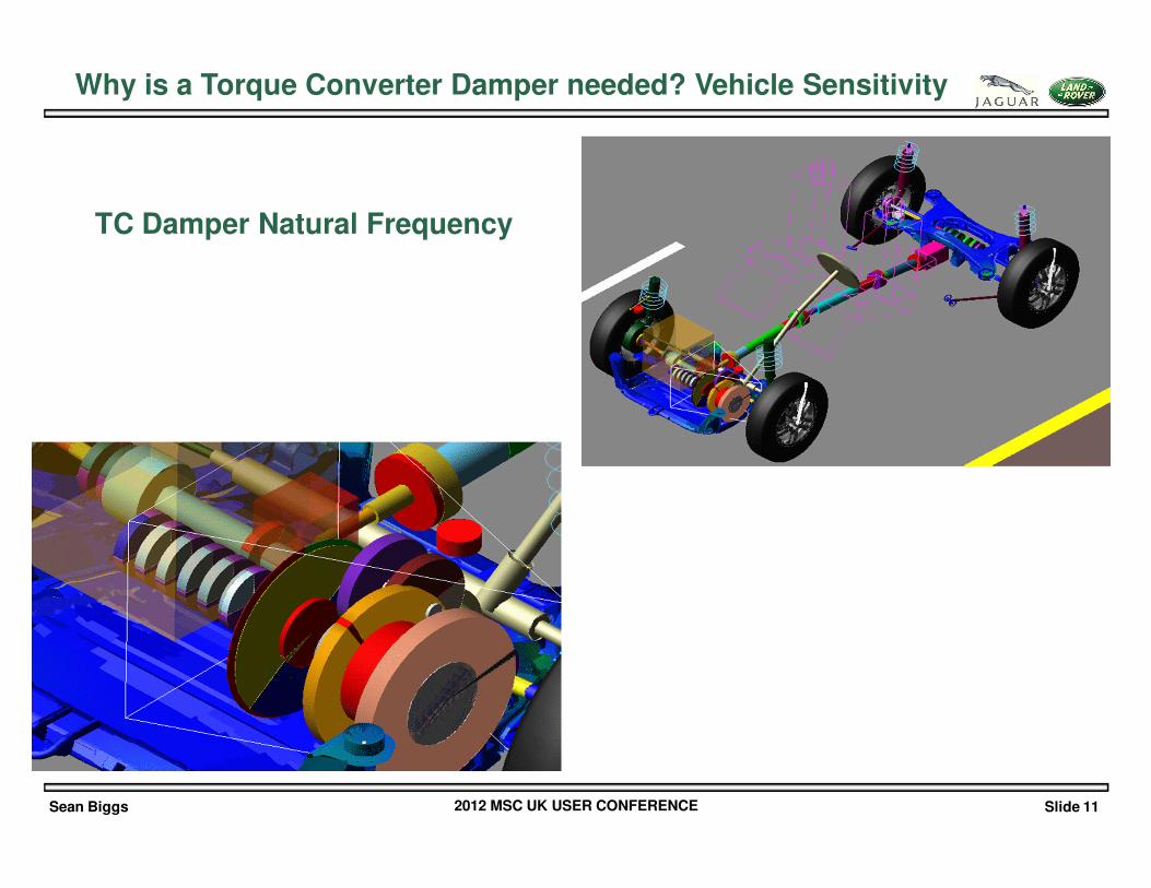
Why is a Torque Converter Damper needed? Vehicle Sensitivity
TC Damper Natural Frequency
Sean Biggs 2012 MSC UK USER CONFERENCE Slide 12
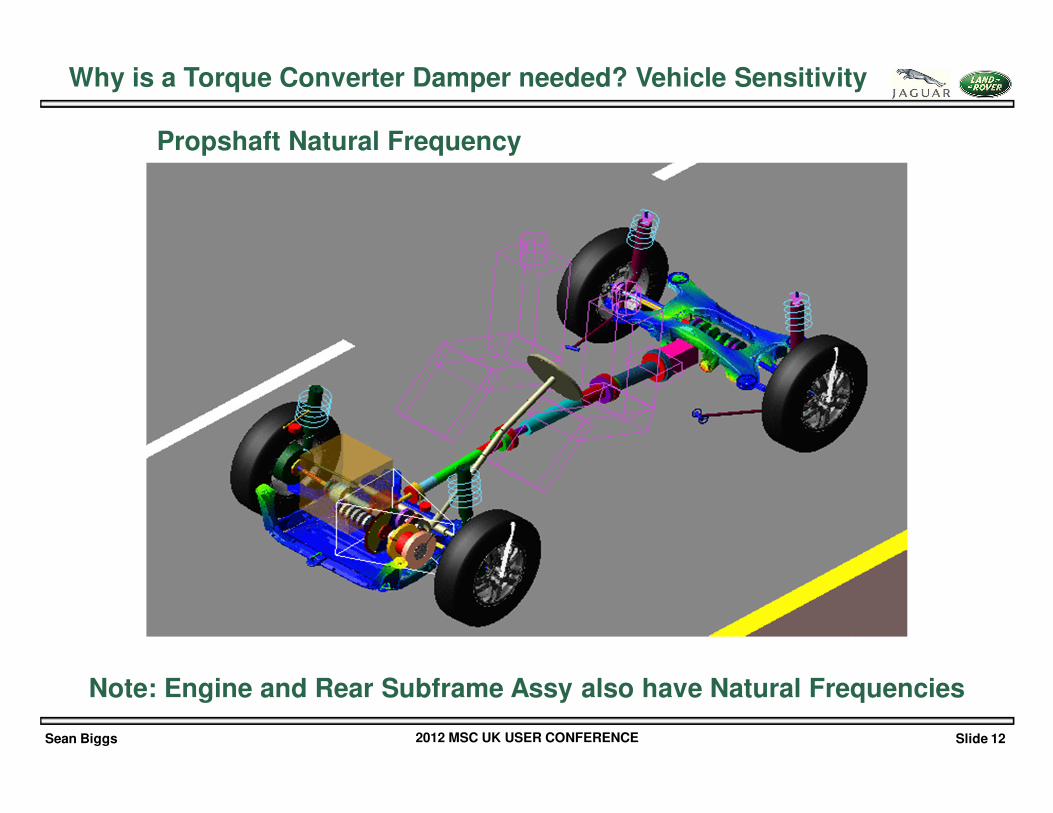
Why is a Torque Converter Damper needed? Vehicle Sensitivity
Propshaft Natural Frequency
Note: Engine and Rear Subframe Assy also have Natural Frequencies
Sean Biggs 2012 MSC UK USER CONFERENCE Slide 13
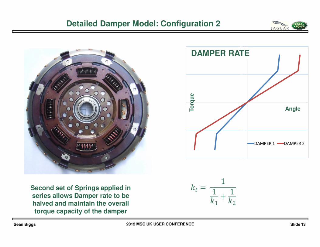
Detailed Damper Model: Configuration 2
DAMPER RATE
AngleTo
rqu
eSecond set of Springs applied in series allows Damper rate to be halved and maintain the overall torque capacity of the damper
Sean Biggs 2012 MSC UK USER CONFERENCE Slide 14
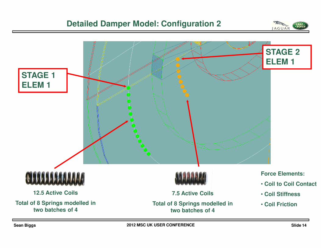
12.5 Active Coils
Total of 8 Springs modelled in two batches of 4
STAGE 1 ELEM 1
Force Elements:
• Coil to Coil Contact
• Coil Stiffness
• Coil Friction
STAGE 2 ELEM 1
7.5 Active Coils
Total of 8 Springs modelled in two batches of 4
Detailed Damper Model: Configuration 2
Sean Biggs 2012 MSC UK USER CONFERENCE Slide 15
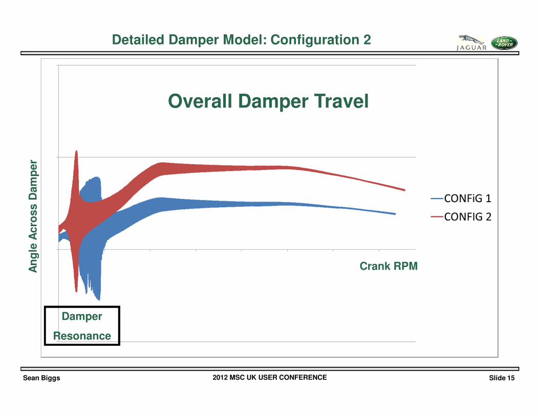
Detailed Damper Model: Configuration 2
Overall Damper Travel
Crank RPMAn
gle
Acro
ss D
am
per
Damper
Resonance
Sean Biggs 2012 MSC UK USER CONFERENCE Slide 16
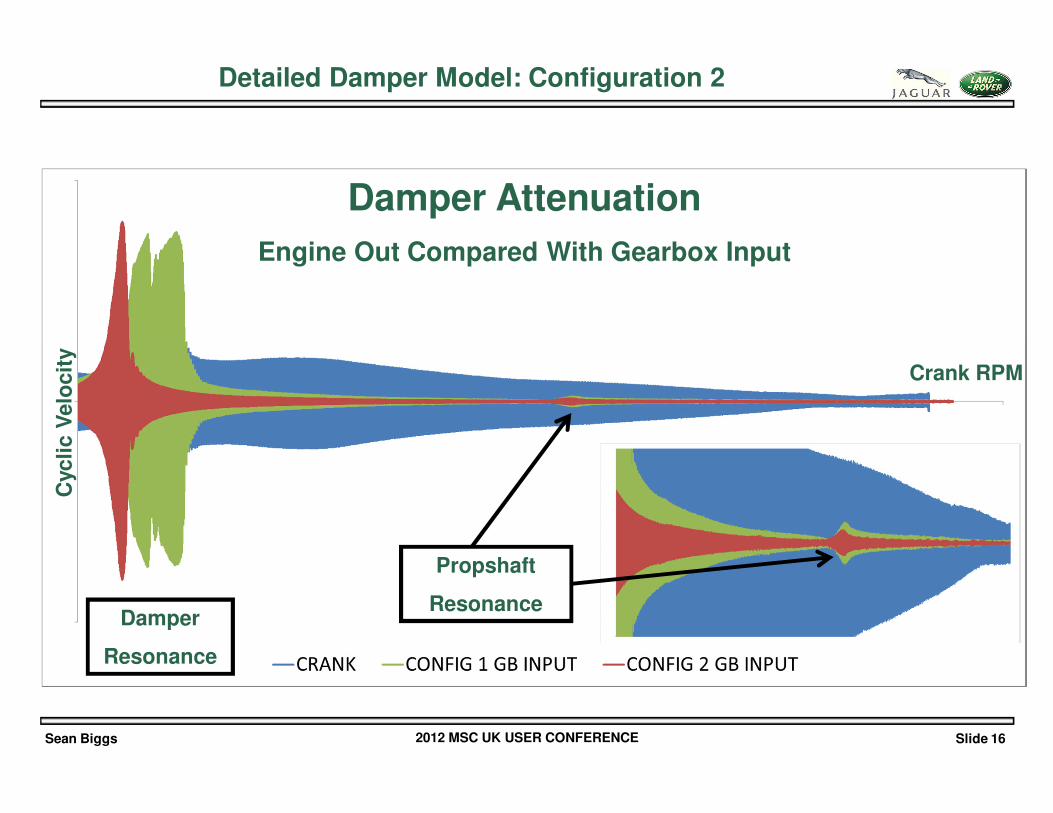
Detailed Damper Model: Configuration 2
Damper Attenuation
Engine Out Compared With Gearbox Input
Crank RPM
Cyc
lic V
elo
cit
y
Propshaft
ResonanceDamper
Resonance
Sean Biggs 2012 MSC UK USER CONFERENCE Slide 17
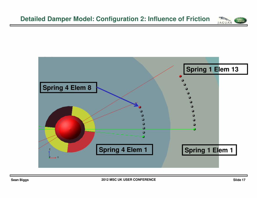
Spring 4 Elem 8
Spring 4 Elem 1 Spring 1 Elem 1
Spring 1 Elem 13
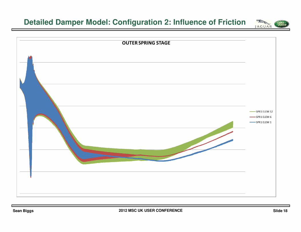
Detailed Damper Model: Configuration 2: Influence of Friction
Sean Biggs 2012 MSC UK USER CONFERENCE Slide 18
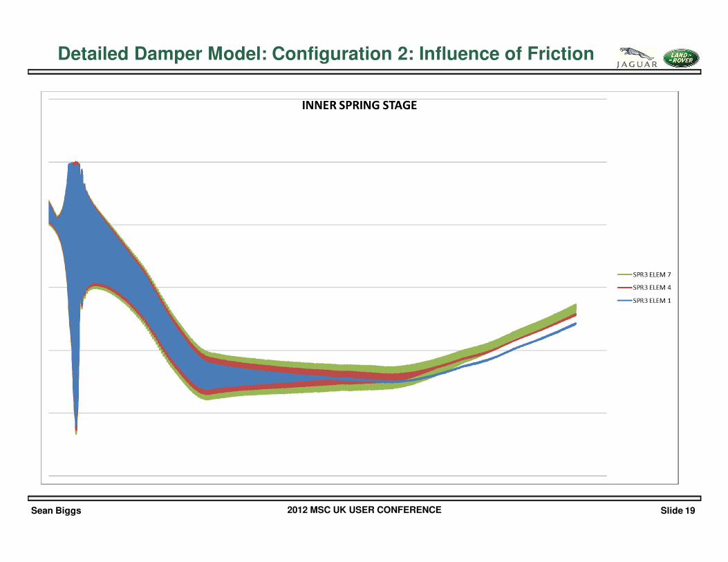
Detailed Damper Model: Configuration 2: Influence of Friction
Sean Biggs 2012 MSC UK USER CONFERENCE Slide 19
Detailed Damper Model: Configuration 2: Influence of Friction
Sean Biggs 2012 MSC UK USER CONFERENCE Slide 20
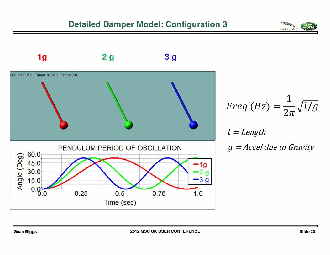
1g 2 g 3 g
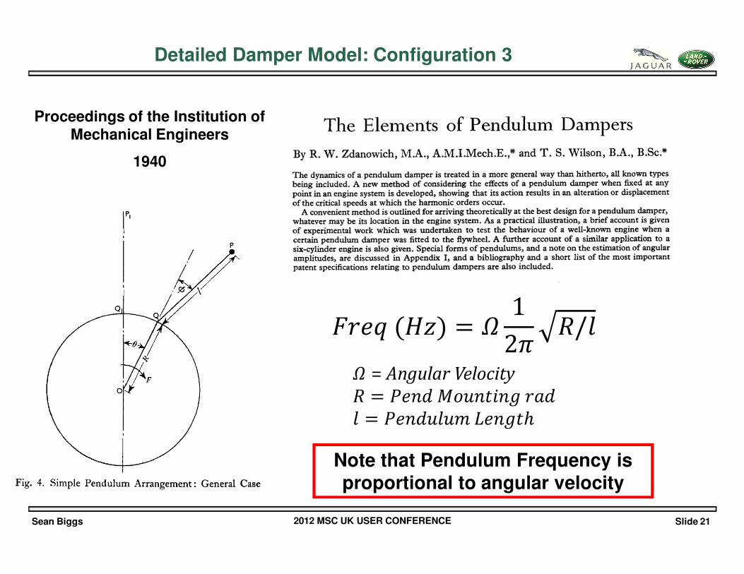
Detailed Damper Model: Configuration 3
Sean Biggs 2012 MSC UK USER CONFERENCE Slide 21
Proceedings of the Institution of Mechanical Engineers
1940
Note that Pendulum Frequency is proportional to angular velocity
Detailed Damper Model: Configuration 3
Sean Biggs 2012 MSC UK USER CONFERENCE Slide 22
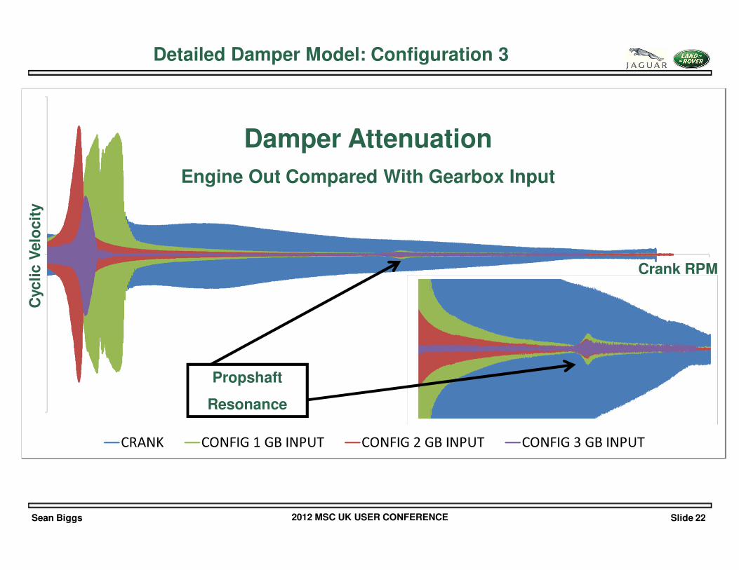
Detailed Damper Model: Configuration 3
Damper Attenuation
Engine Out Compared With Gearbox Input
Crank RPM
Cyc
lic V
elo
cit
y
Propshaft
Resonance
Sean Biggs 2012 MSC UK USER CONFERENCE Slide 23
• Forcing levels for driveline systems are increasing
• Traditional methods of decoupling the forcing are not now available
• The Mechanical system response is highly non-linear and complex
• TC Damper designs are becoming increasingly sophisticated
• MSC Adams allows a detailed understanding of the complete system to be obtained
Conclusions
Sean Biggs 2012 MSC UK USER CONFERENCE Slide 24
The Author would like to acknowledge the contributions of the JLR CAE and NVH Test team that made the presentation of this
paper possible
The Tyre model used for the analysis was provided by Dr Matthew Bartram of Loughborough University
Acknowledgements


![Torque Converter Voith Torque Converter[1]](https://img.pdfslide.us/doc/110x75/55cf992e550346d0339c0bc5/torque-converter-voith-torque-converter1.jpg)