Embed Size (px)
Citation preview
What Does the Scene Look Like From a Scene Point?
Donald TanguayAugust 7, 2002
M. Irani, T. Hassner, and P. AnandanECCV 2002
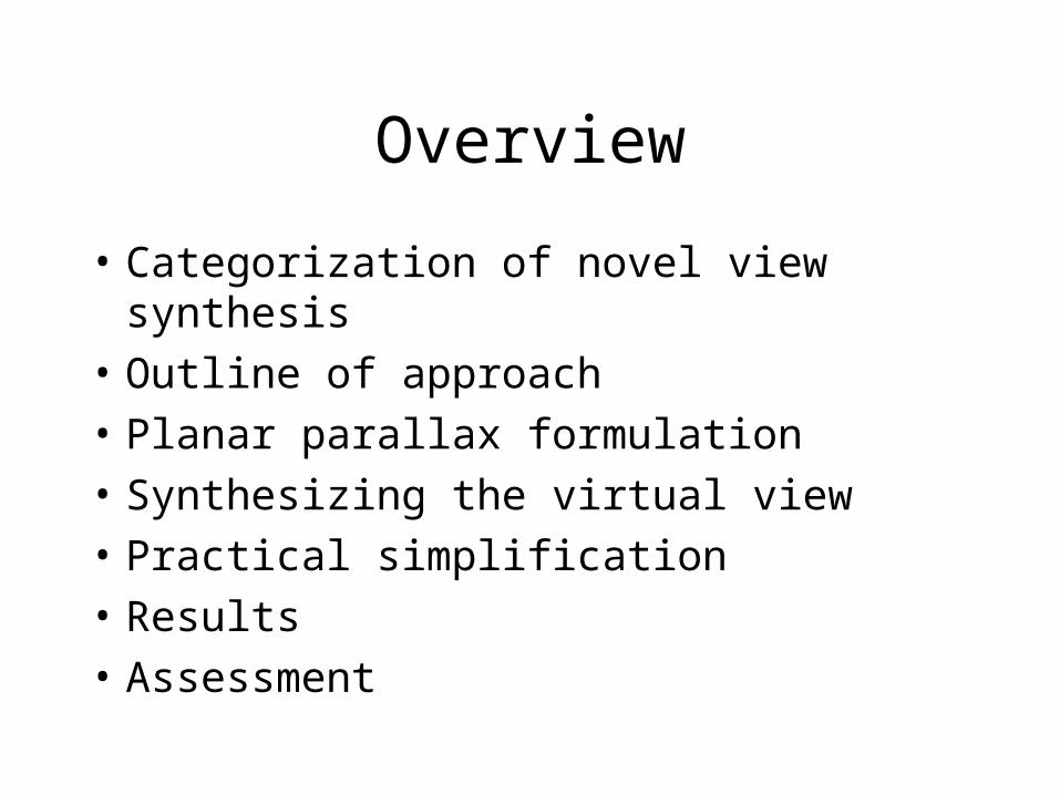
Overview
• Categorization of novel view synthesis
• Outline of approach
• Planar parallax formulation
• Synthesizing the virtual view
• Practical simplification
• Results
• Assessment
Novel View Synthesis
Breakdown into 3 categories:
• 3D reconstruction
• View transfer
• Sampling methods
3D Reconstruction
• Fully reconstruct scene, then render view
• Geometric error criteria do not translate well to errors in novel view
• Reconstruction and rendering occur in different coordinate systems
• Problems amplified with novel viewpoints significantly different from real cameras
“View Transfer”
• For example: 2 images, dense correspondence, and trifocal tensor
• Avoids reconstruction• Errors in correspondence• Synthesis uses forward warping step, which
results in “hole-filling” at surface discontinuities• Problems amplified by severe changes in
viewpoint
Sampling Methods
• E.g., lightfield and lumigraph
• Avoid reconstruction and correspondence
• Require very large sampling of view-space
• Data acquisition is problematic
• Space-time costs are impractical
Features of Their Method
• Avoids reconstruction, correspondence
• Backward (“inverse”) warping avoids holes
• Optimizes errors in coordinate system of novel view
• Handles significantly different viewpoints
• Small number of input images (~10)
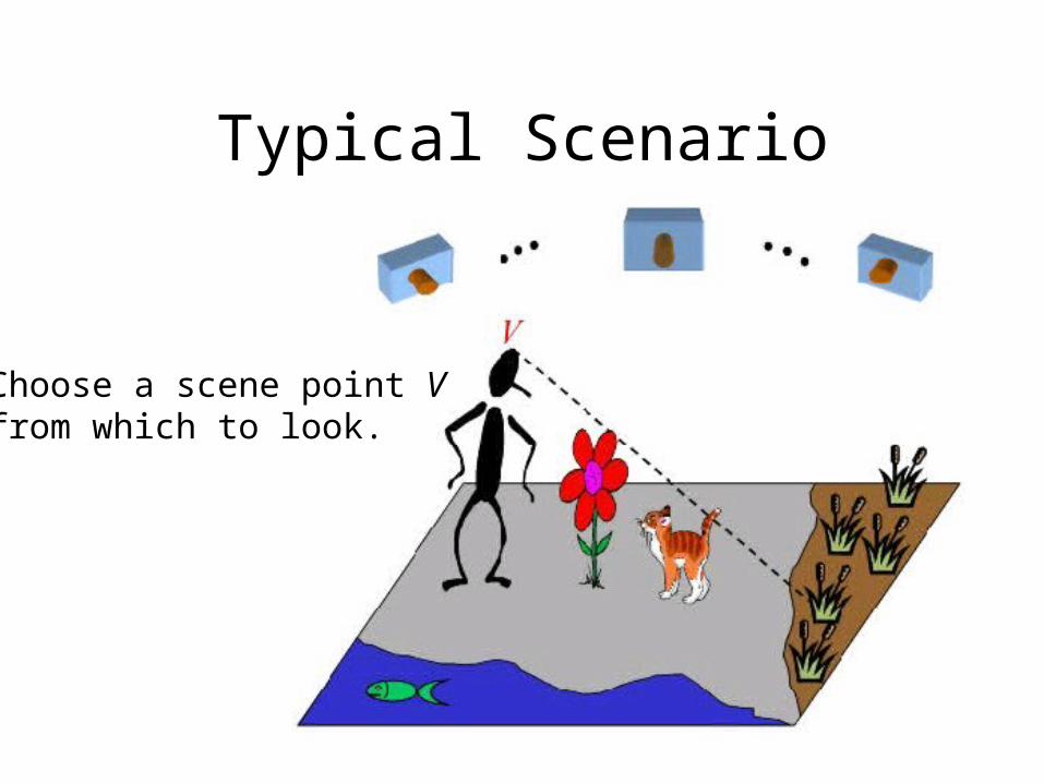
Typical Scenario
Choose a scene point Vfrom which to look.
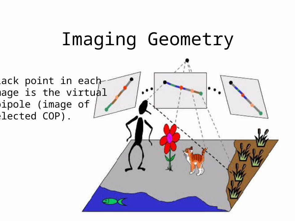
Imaging Geometry
Black point in eachimage is the virtualepipole (image ofselected COP).
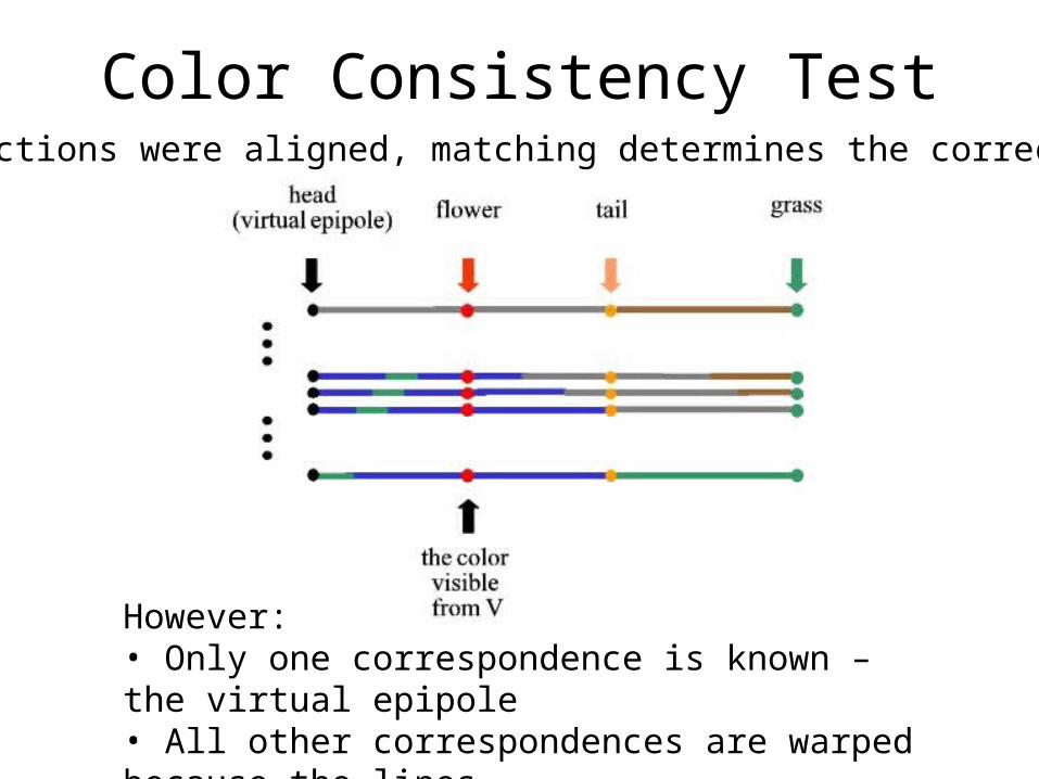
Color Consistency Test
However:• Only one correspondence is known – the virtual epipole• All other correspondences are warped because the lines are in different coordinate systems.
If projections were aligned, matching determines the correct color:
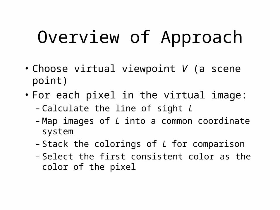
Overview of Approach
• Choose virtual viewpoint V (a scene point)
• For each pixel in the virtual image:– Calculate the line of sight L– Map images of L into a common coordinate
system– Stack the colorings of L for comparison– Select the first consistent color as the color of
the pixel
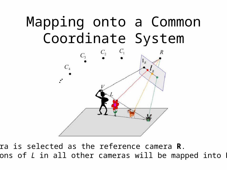
Mapping onto a Common Coordinate System
One camera is selected as the reference camera R.Projections of L in all other cameras will be mapped into R’s image.
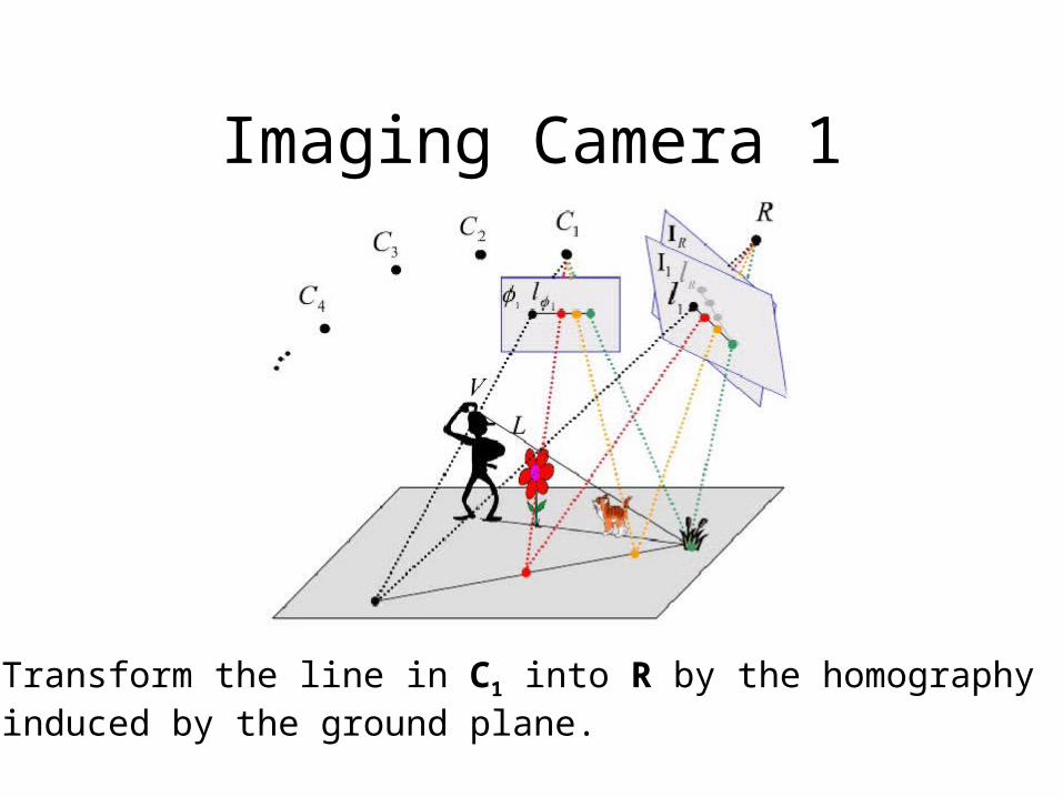
Imaging Camera 1
Transform the line in C1 into R by the homographyinduced by the ground plane.
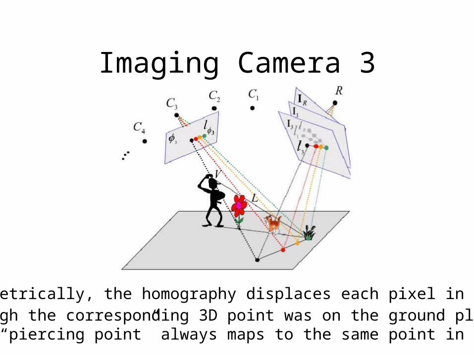
Imaging Camera 3
Geometrically, the homography displaces each pixel in Ci asthough the corresponding 3D point was on the ground plane.The “piercing point” always maps to the same point in R.
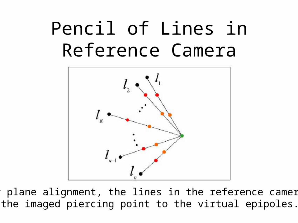
Pencil of Lines inReference Camera
After plane alignment, the lines in the reference camera fanfrom the imaged piercing point to the virtual epipoles.
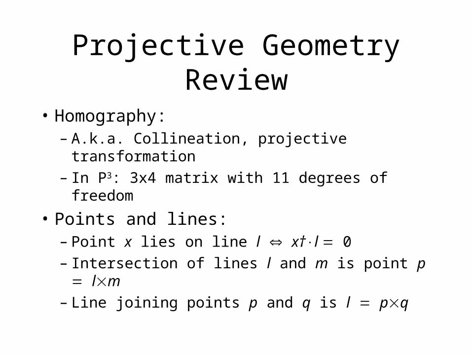
Projective Geometry Review
• Homography:– A.k.a. Collineation, projective transformation– In P3: 3x4 matrix with 11 degrees of freedom
• Points and lines:– Point x lies on line l x†l 0– Intersection of lines l and m is point p lm– Line joining points p and q is l pq
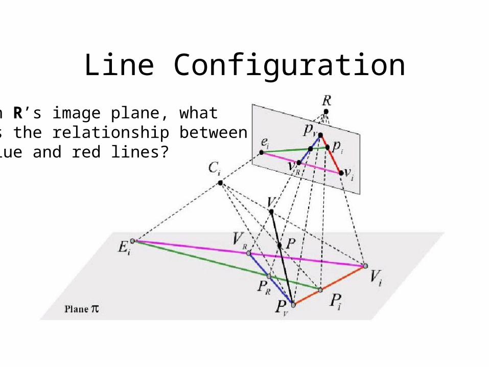
Line Configuration
In R’s image plane, whatis the relationship betweenblue and red lines?
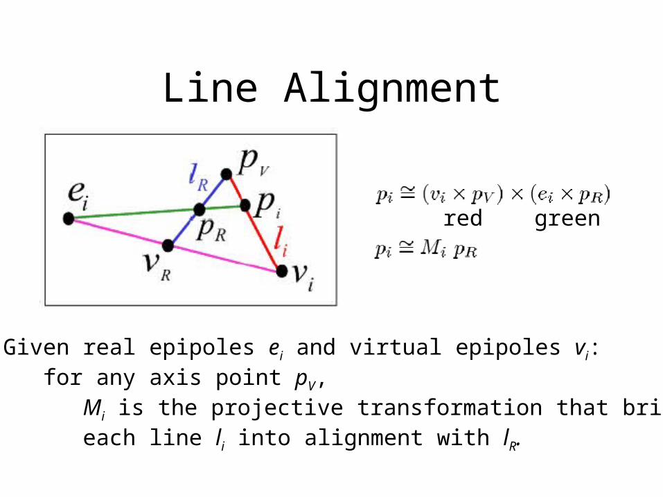
Line Alignment
red green
Given real epipoles ei and virtual epipoles vi: for any axis point pV, Mi is the projective transformation that brings each line li into alignment with lR.
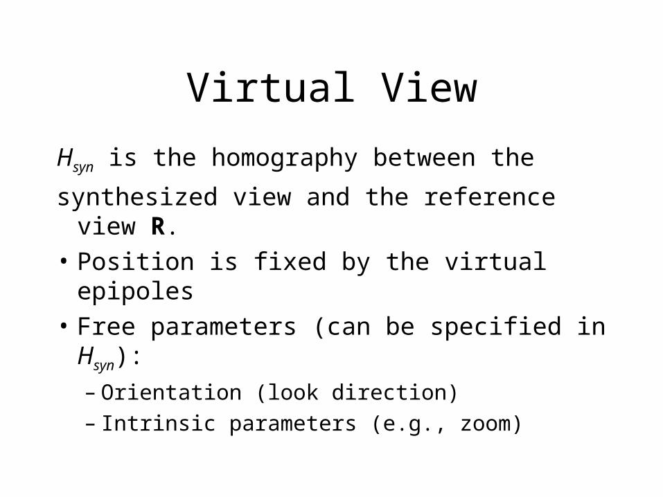
Virtual View
Hsyn is the homography between the
synthesized view and the reference view R.
• Position is fixed by the virtual epipoles
• Free parameters (can be specified in Hsyn):
– Orientation (look direction)– Intrinsic parameters (e.g., zoom)
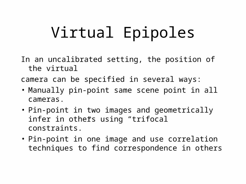
Virtual Epipoles
In an uncalibrated setting, the position of the virtual
camera can be specified in several ways:• Manually pin-point same scene point in all
cameras.• Pin-point in two images and geometrically infer in
others using “trifocal constraints.”• Pin-point in one image and use correlation
techniques to find correspondence in others
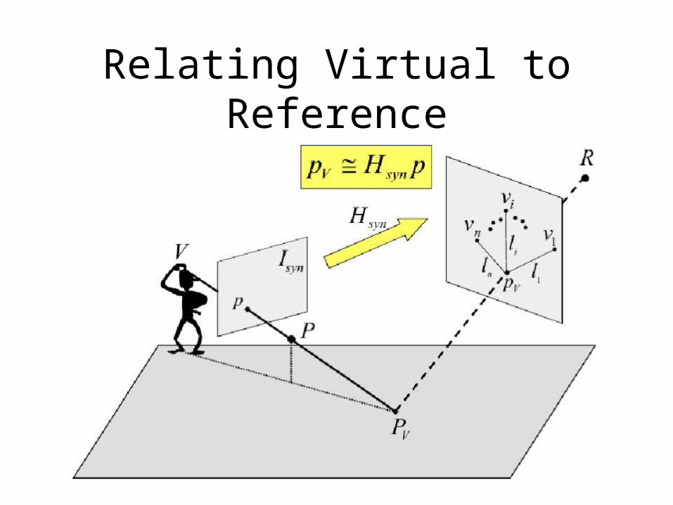
Relating Virtual to Reference
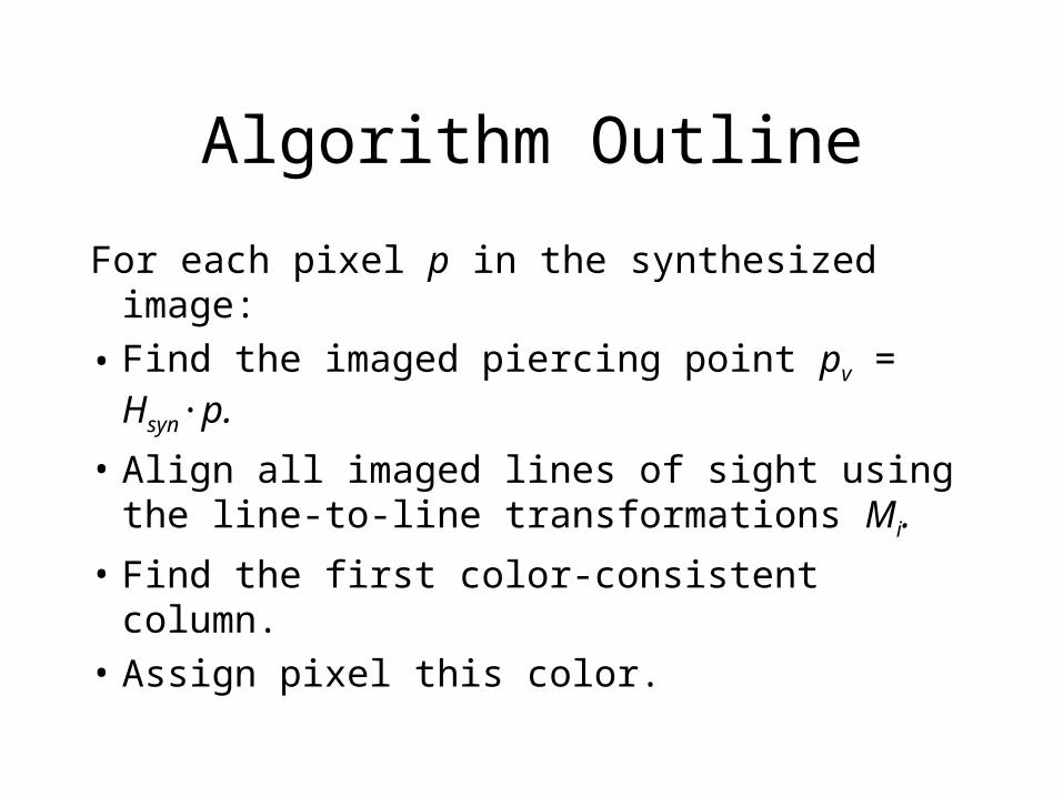
Algorithm Outline
For each pixel p in the synthesized image:
• Find the imaged piercing point pv = Hsyn·p.
• Align all imaged lines of sight using the line-to-line transformations Mi.
• Find the first color-consistent column.
• Assign pixel this color.
Color Consistency
• Assume Lambertian objects.• A is a (n+1)3 matrix of the column of
colors in YIQ color space. is the maximal eigenvalue of the covariance
matrix of A.• Select first column with under a threshold.• Paint with the median color of that column.
Important Details
• Local “smoothing”: They prefer color consistent columns whose 3D position is spatially consistent with that of neighboring pixels.
• Uniform regions: They flag used pixels in source images to prevent their repeated matching.
• Pixel scanning order: They evaluate for physical points closer to ground plane first; then farther.
• Ground subtraction: Except for piercing point, remove ground plane from coloring stack
Practical Simplification
• Cameras are coplanar
• Real epipoles lie on a line in R
• Rectifying R into the “nadir view” makes the line of epipoles go to infinity
• The Mi line-to-line transformations become affine – simple linear stretching of the lines
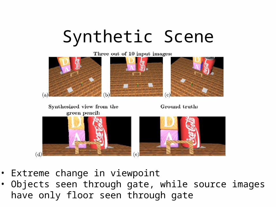
Synthetic Scene
• Extreme change in viewpoint• Objects seen through gate, while source images have only floor seen through gate
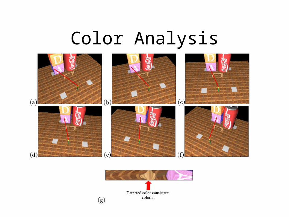
Color Analysis
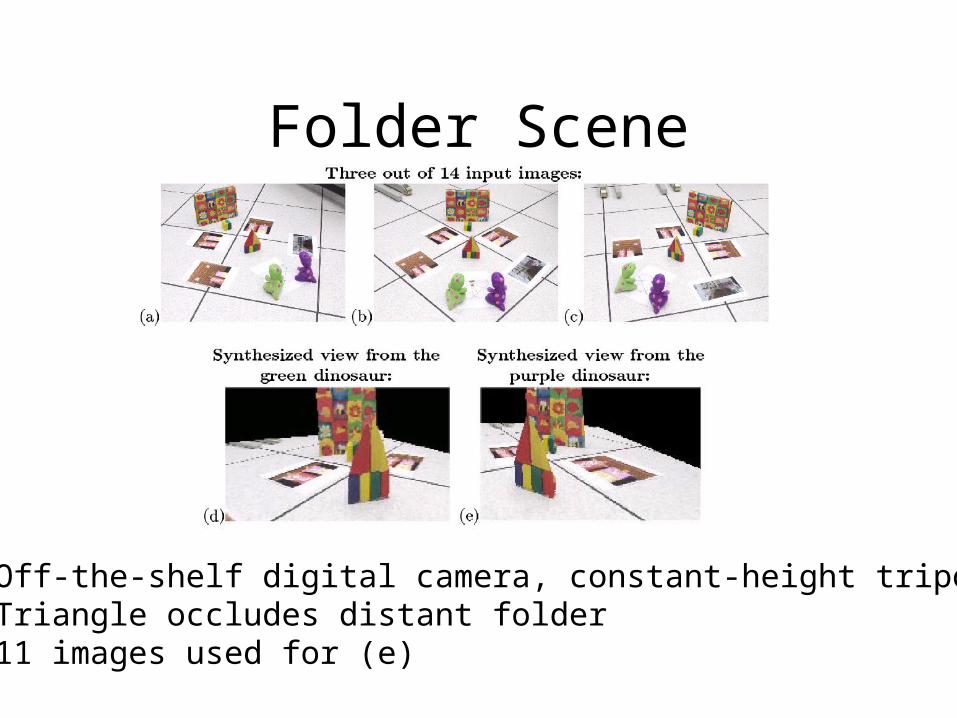
Folder Scene
• Off-the-shelf digital camera, constant-height tripod• Triangle occludes distant folder• 11 images used for (e)
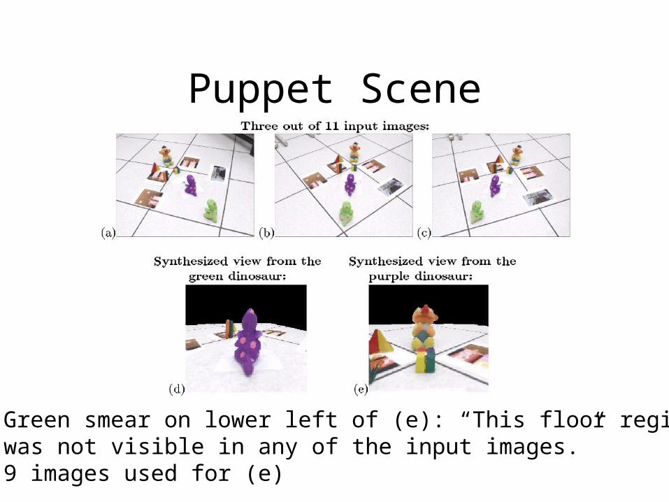
Puppet Scene
• Green smear on lower left of (e): “This floor region was not visible in any of the input images.”• 9 images used for (e)
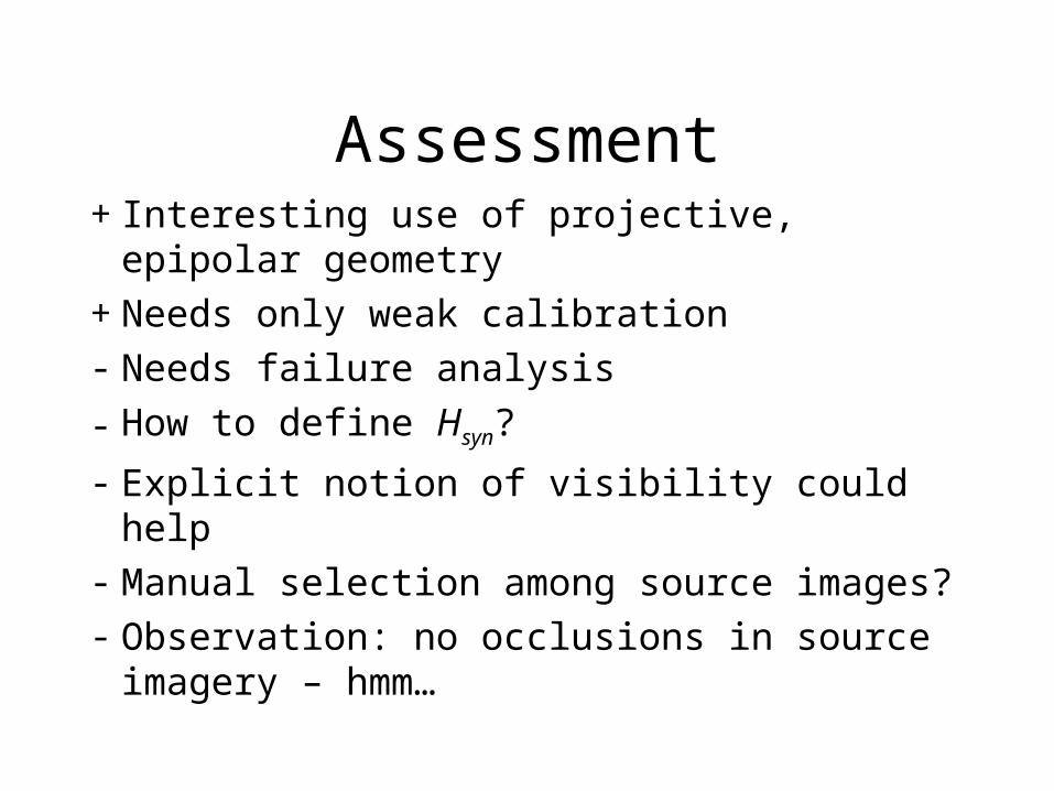
Assessment+ Interesting use of projective, epipolar
geometry+ Needs only weak calibration- Needs failure analysis
- How to define Hsyn?
- Explicit notion of visibility could help- Manual selection among source images?- Observation: no occlusions in source
imagery – hmm…