Embed Size (px)
Citation preview
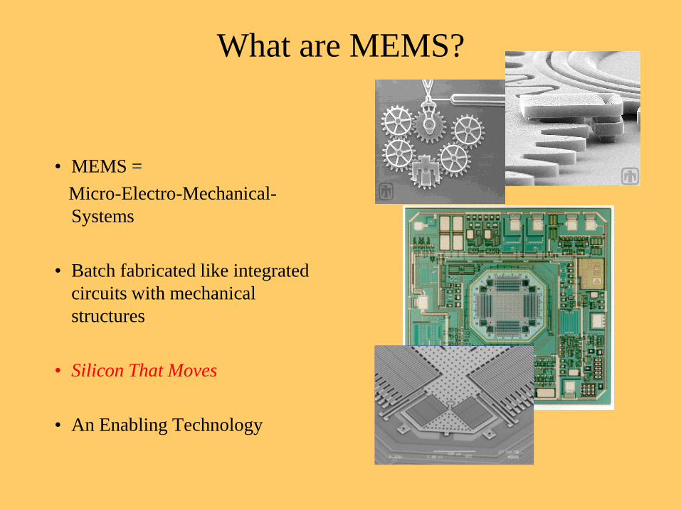
What are MEMS?
• MEMS =
Micro-Electro-Mechanical-
Systems
• Batch fabricated like integrated
circuits with mechanical
structures
• Silicon That Moves
• An Enabling Technology
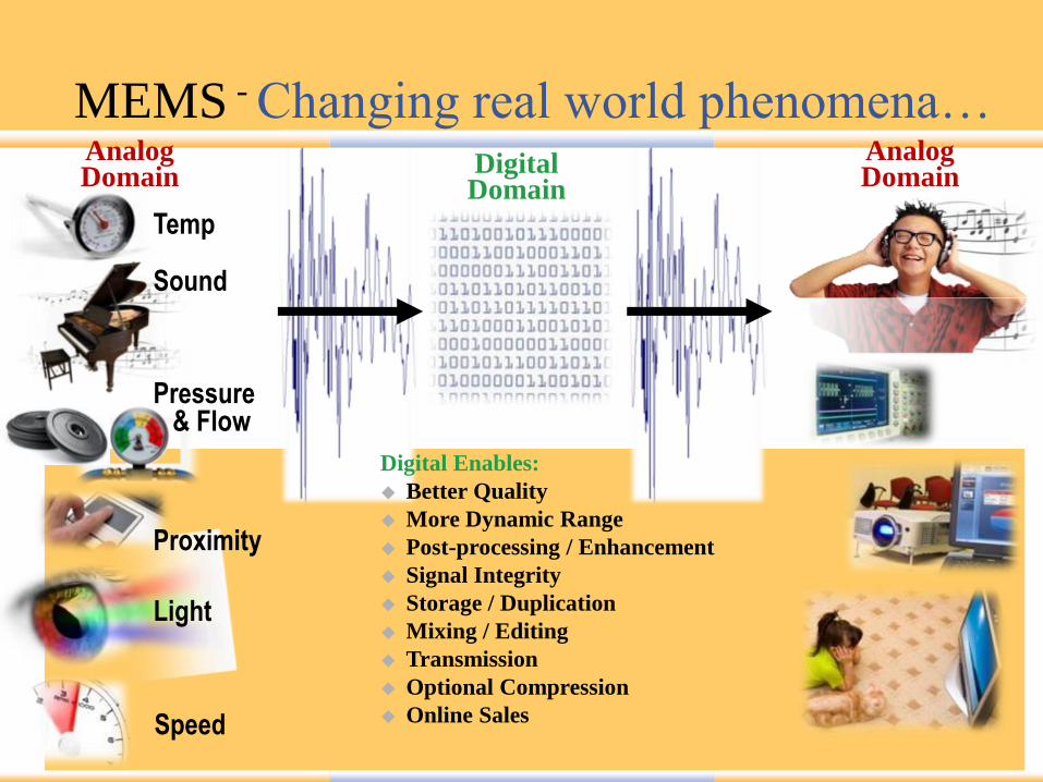
MEMS - Changing real world phenomena…
Light
Sound
Temp
Pressure& Flow
Speed
Proximity
AnalogDomain
DigitalDomain
AnalogDomain
Digital Enables:
Better Quality
More Dynamic Range
Post-processing / Enhancement
Signal Integrity
Storage / Duplication
Mixing / Editing
Transmission
Optional Compression
Online Sales
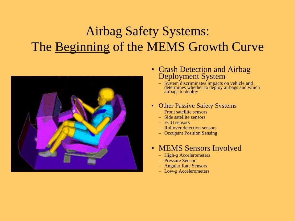
Airbag Safety Systems:
The Beginning of the MEMS Growth Curve
• Crash Detection and Airbag Deployment System– System discriminates impacts on vehicle and
determines whether to deploy airbags and which airbags to deploy
• Other Passive Safety Systems– Front satellite sensors– Side satellite sensors– ECU sensors– Rollover detection sensors– Occupant Position Sensing
• MEMS Sensors Involved– High-g Accelerometers– Pressure Sensors– Angular Rate Sensors– Low-g Accelerometers
MEMS Test - What really IS different?
From a pure electrical test perspective not much is different.
•Mixed signal analysis, precision DC measurement, wave form generators,
digital subsystem
•Standard Tester requirements
•Ported to several commercial testers
MEMS Test - What really IS different?
From a mechanical perspective things are very different.
It’s silicon that MOVES!
•Part must be “handed off” to test fixture and clamped rigidly
•Precisely aligned
•No parametric shift
•Electrical parametric measure in the presence of the mechanical stimulus
•Maintain contact during mechanical and thermal flows
•Multi Axis test requirement
•Shake, Flip or Rotate
•Reference instrumentation
•Mechanical Noise or Vibration concerns
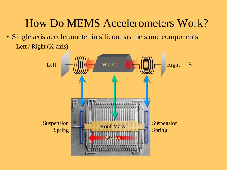
How Do MEMS Accelerometers Work?• Single axis accelerometer in silicon has the same components
– Left / Right (X-axis)
XLeft RightM a s s
Proof MassSuspension
Spring
Suspension
Spring
Motion
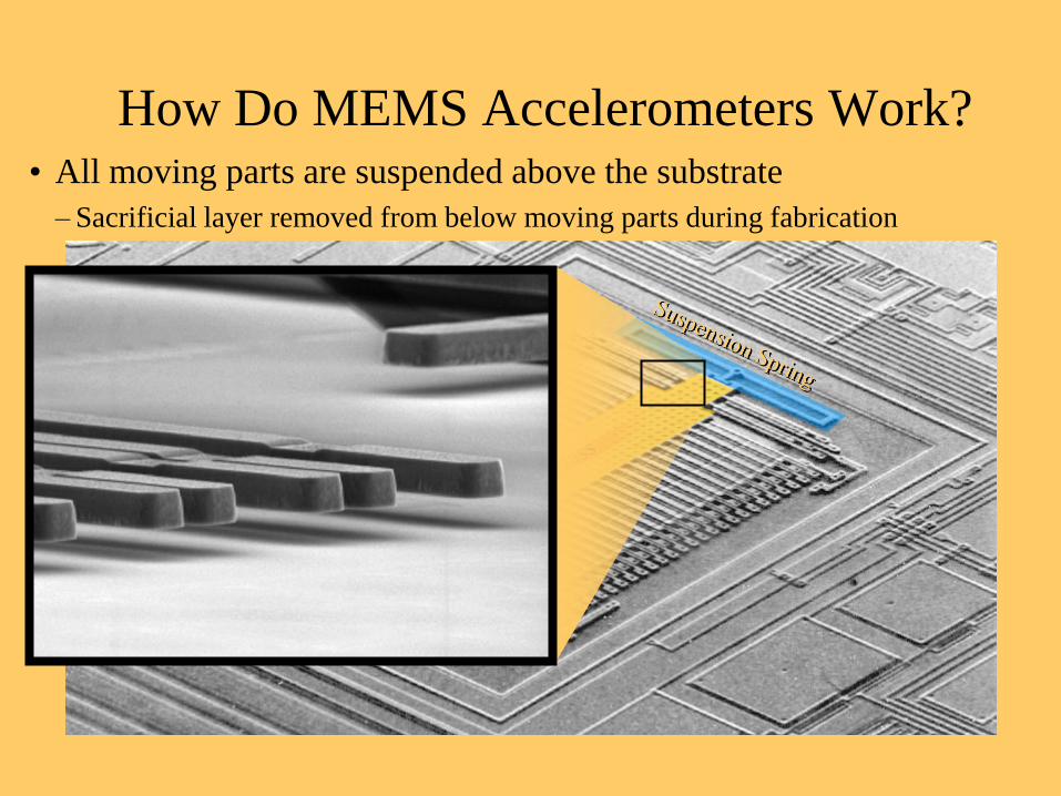
How Do MEMS Accelerometers Work?• All moving parts are suspended above the substrate
– Sacrificial layer removed from below moving parts during fabrication
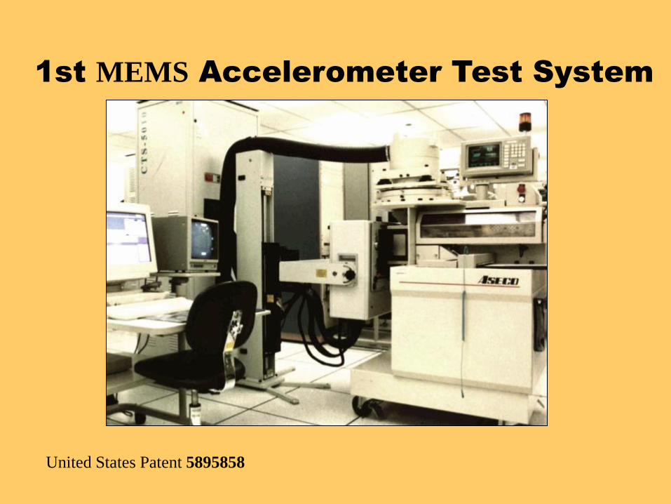
1st MEMS Accelerometer Test System
United States Patent 5895858
MEMS Test Challenges "Most semiconductor industry engineers have a mechanical background or an
electrical background, which is sufficient to test any type of semiconductor
product," notes Sami.
"However, since MEMS consist of both electrical and mechanical components, the
testing become complex and not many have the technical training required to
perform the tests."
To overcome this issue of customers' ignorance, test vendors have begun to focus
on educating end users on the importance of MEMS testing as well as the
benefits they are likely to obtain. Once customers recognize the true value of
testing, the adoption rates are expected to increase significantly.
Frost and Sullivan - MEMS Test Equipment Market Responds to Need for Low-Cost Products and End-User Education
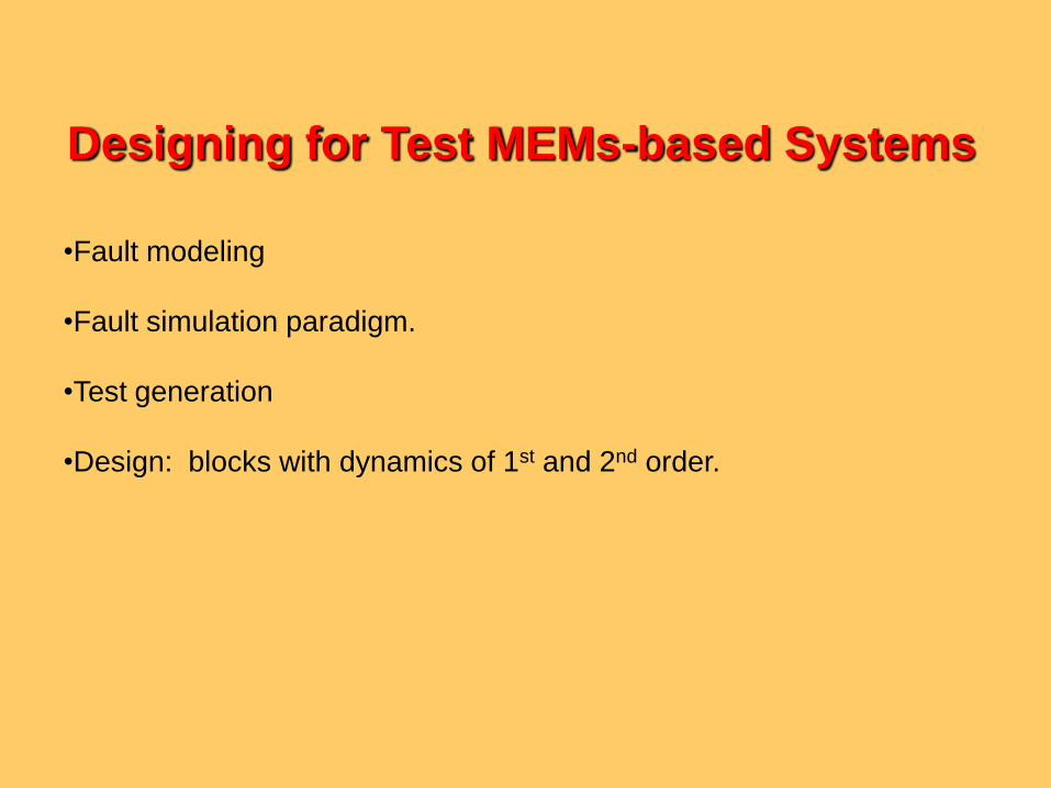
•Fault modeling
•Fault simulation paradigm.
•Test generation
•Design: blocks with dynamics of 1st and 2nd order.
Designing for Test MEMs-based Systems
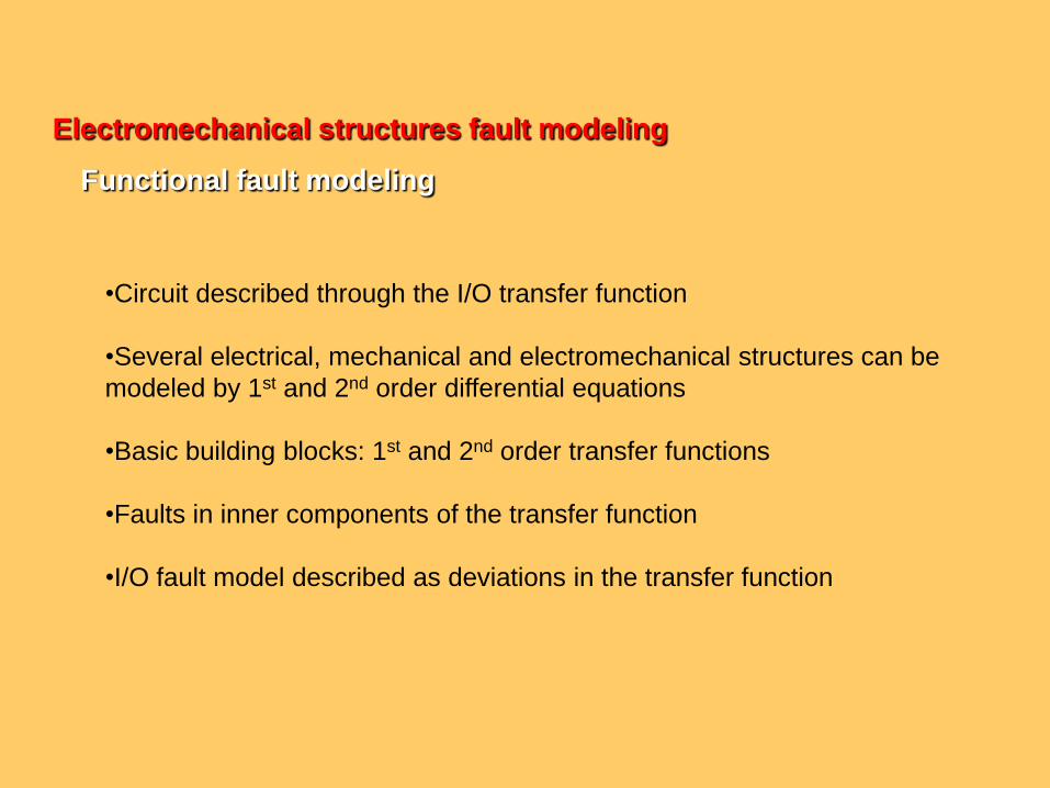
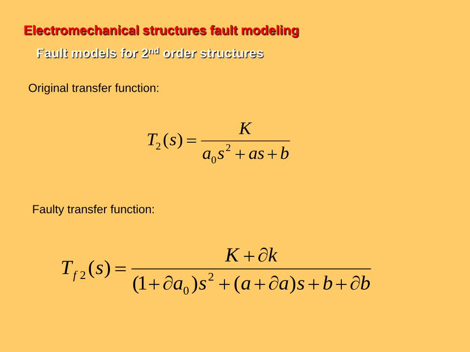
Electromechanical structures fault modeling
Functional fault modeling
•Circuit described through the I/O transfer function
•Several electrical, mechanical and electromechanical structures can be
modeled by 1st and 2nd order differential equations
•Basic building blocks: 1st and 2nd order transfer functions
•Faults in inner components of the transfer function
•I/O fault model described as deviations in the transfer function
21 nd
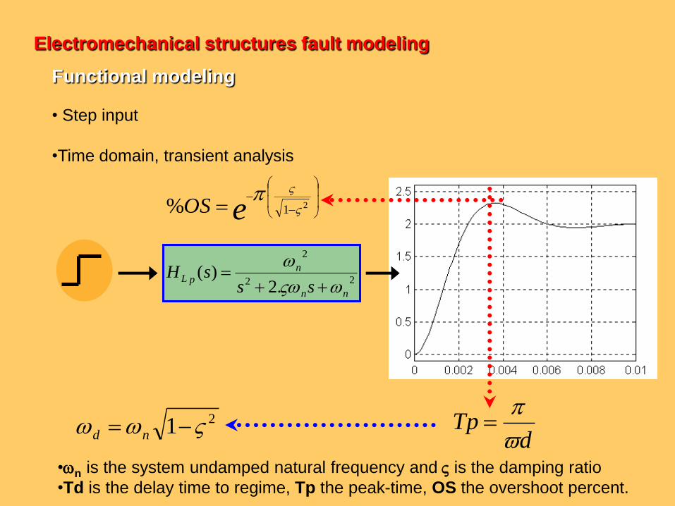
• Step input
•Time domain, transient analysis
dTp
22
2
.2)(
nn
n
pLss
sH
eOS
21%
•n is the system undamped natural frequency and is the damping ratio
•Td is the delay time to regime, Tp the peak-time, OS the overshoot percent.
Electromechanical structures fault modeling
Functional modeling
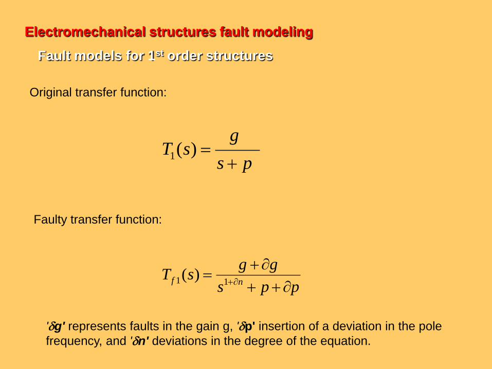
Original transfer function:
ps
gsT
)(1
pps
ggsT
nf
11 )(
'g' represents faults in the gain g, 'p' insertion of a deviation in the pole
frequency, and 'n' deviations in the degree of the equation.
Faulty transfer function:
Electromechanical structures fault modeling
Fault models for 1st order structures
bassa
KsT
2
0
2 )(
bbsaasa
kKsT f
)()1()(
2
0
2
Electromechanical structures fault modeling
Fault models for 2nd order structures
Original transfer function:
Faulty transfer function:
•Transient Response Analysis Method (TRAM)
•Use of compact test vectors
•Test vectors confirmed through fault simulation (FS)
•Fault dictionary based on the circuit's time response
Test vector generation
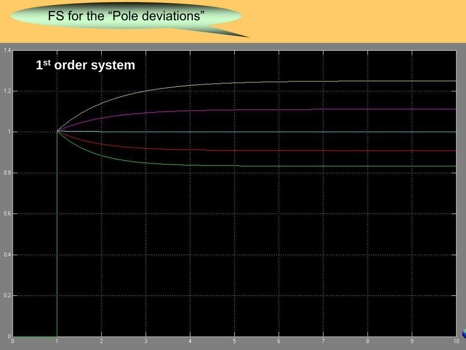
FS for the “Pole deviations”
1st order system
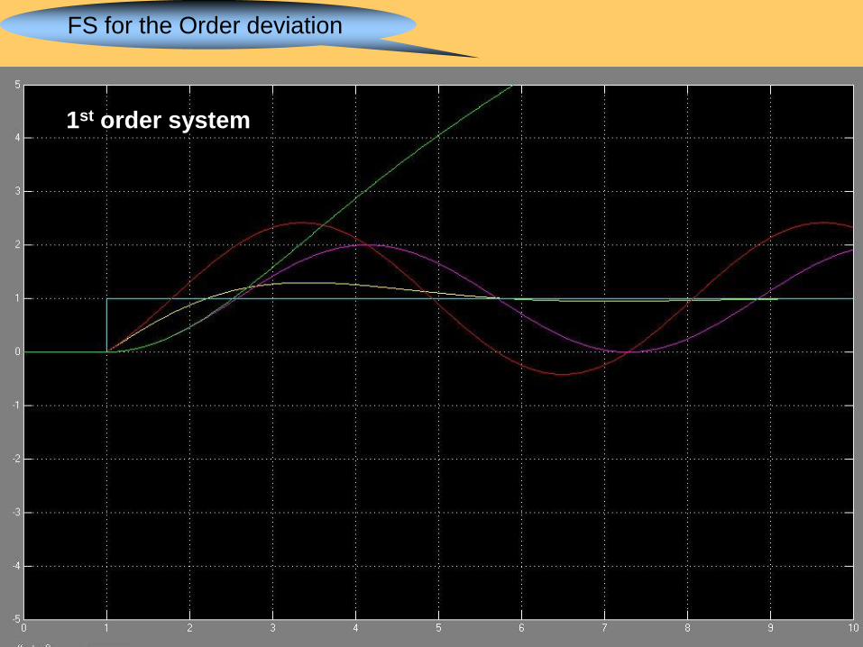
FS for the Order deviation
1st order system
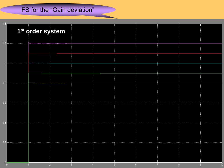
FS for the “Gain deviation”
1st order system
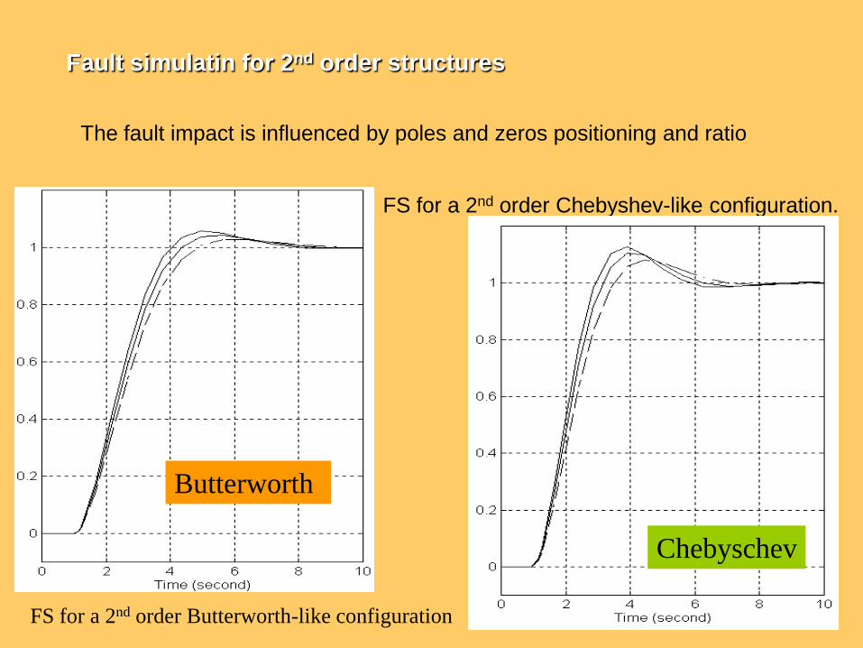
The fault impact is influenced by poles and zeros positioning and ratio
FS for a 2nd order Butterworth-like configuration
FS for a 2nd order Chebyshev-like configuration.
Butterworth
Chebyschev
Fault simulatin for 2nd order structures
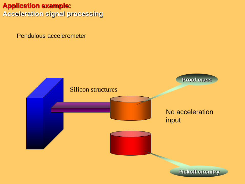
Application example:
Acceleration signal processing
Pendulous accelerometer
No acceleration
input
Pickoff circuitry
Proof mass
Silicon structures
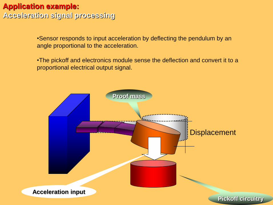
•Sensor responds to input acceleration by deflecting the pendulum by an
angle proportional to the acceleration.
•The pickoff and electronics module sense the deflection and convert it to a
proportional electrical output signal.
Application example:
Acceleration signal processing
Pickoff circuitry
Proof mass
Acceleration input
Displacement
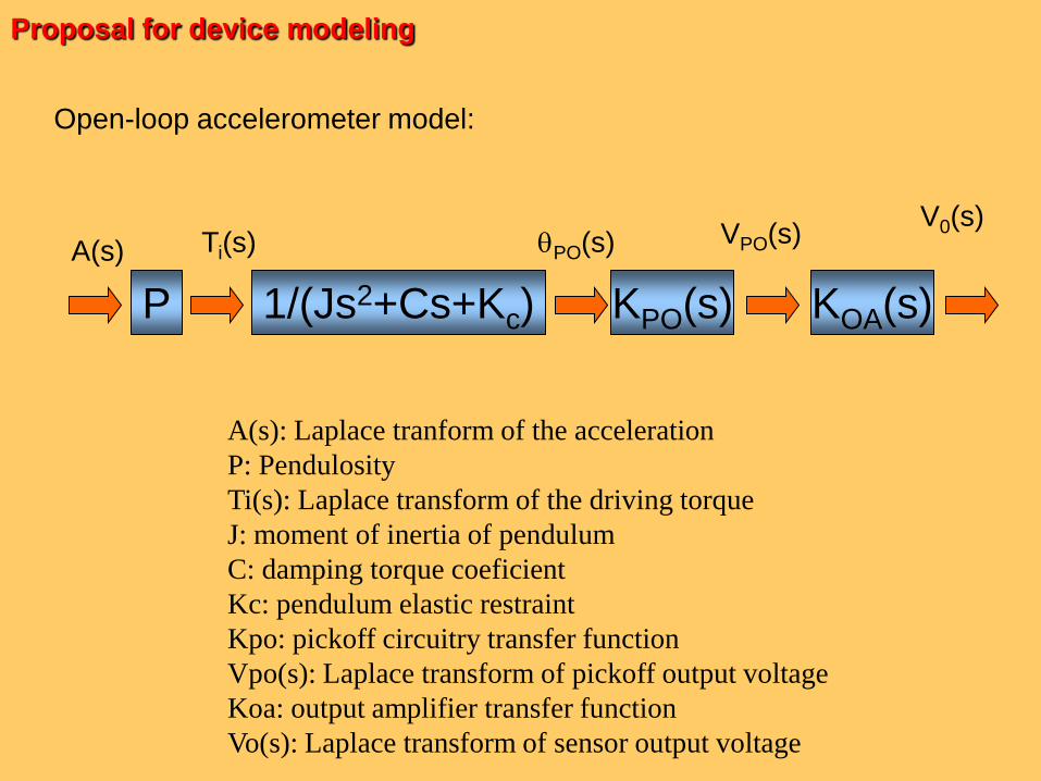
Open-loop accelerometer model:
P
A(s)
1/(Js2+Cs+Kc)
Ti(s)
KPO(s)
PO(s)
KOA(s)
VPO(s)V0(s)
A(s): Laplace tranform of the acceleration
P: Pendulosity
Ti(s): Laplace transform of the driving torque
J: moment of inertia of pendulum
C: damping torque coeficient
Kc: pendulum elastic restraint
Kpo: pickoff circuitry transfer function
Vpo(s): Laplace transform of pickoff output voltage
Koa: output amplifier transfer function
Vo(s): Laplace transform of sensor output voltage
Proposal for device modeling
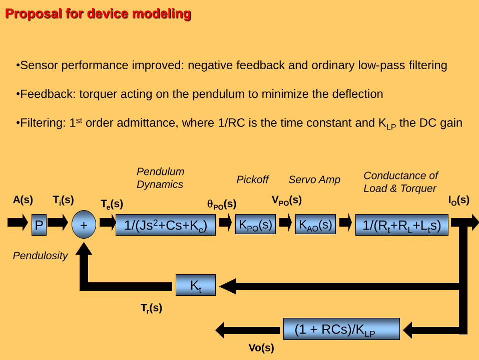
•Sensor performance improved: negative feedback and ordinary low-pass filtering
•Feedback: torquer acting on the pendulum to minimize the deflection
•Filtering: 1st order admittance, where 1/RC is the time constant and KLP the DC gain
Proposal for device modeling
Pendulosity
1/(Js2+Cs+Kc) KPO(s) KAO(s)P + 1/(Rt+RL+Lts)
Kt
VPO(s)PO(s)A(s) Ti(s) Te(s)
Tr(s)
IO(s)
Pendulum
Dynamics Pickoff Conductance of
Load & TorquerServo Amp
(1 + RCs)/KLP
Vo(s)
Proposal for device modeling
•Sensor performance improved: negative feedback and ordinary low-pass filtering
•Feedback: torquer acting on the pendulum to minimize the deflection
•Filtering: 1st order admittance, where 1/RC is the time constant and KLP the DC gain
Pendulosity
1/(Js2+Cs+Kc) KPO(s) KAO(s)P + 1/(Rt+RL+Lts)
Kt
VPO(s)PO(s)A(s) Ti(s) Te(s)
Tr(s)
IO(s)
Pendulum
Dynamics Pickoff Conductance of
Load & TorquerServo Amp
(1 + RCs)/KLP
Vo(s)
Proposal for device modeling
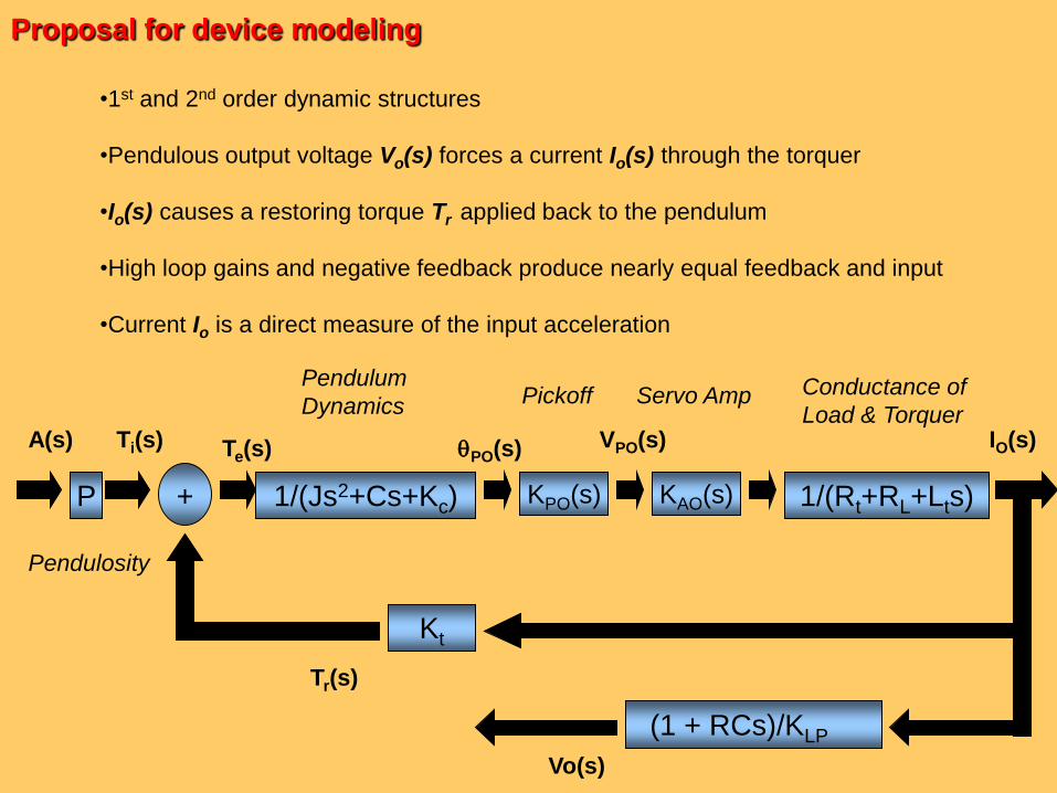
•1st and 2nd order dynamic structures
•Pendulous output voltage Vo(s) forces a current Io(s) through the torquer
•Io(s) causes a restoring torque Tr applied back to the pendulum
•High loop gains and negative feedback produce nearly equal feedback and input
•Current Io is a direct measure of the input acceleration
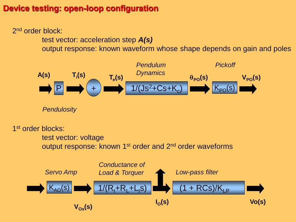
2nd order block:
test vector: acceleration step A(s)
output response: known waveform whose shape depends on gain and poles
1st order blocks:
test vector: voltage
output response: known 1st order and 2nd order waveforms
Device testing: open-loop configuration
Pendulosity
1/(Js2+Cs+Kc) KPO(s)P +
VPO(s)PO(s)A(s) Ti(s) Te(s)
Pendulum
Dynamics
Pickoff
IO(s)
Low-pass filterConductance of
Load & TorquerServo Amp
Vo(s)
KAO(s) 1/(Rt+RL+Lts) (1 + RCs)/KLP
VOs(s)
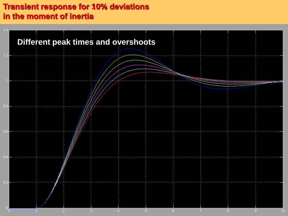
Transient response for 10% deviations
in the moment of inertia
Different peak times and overshoots
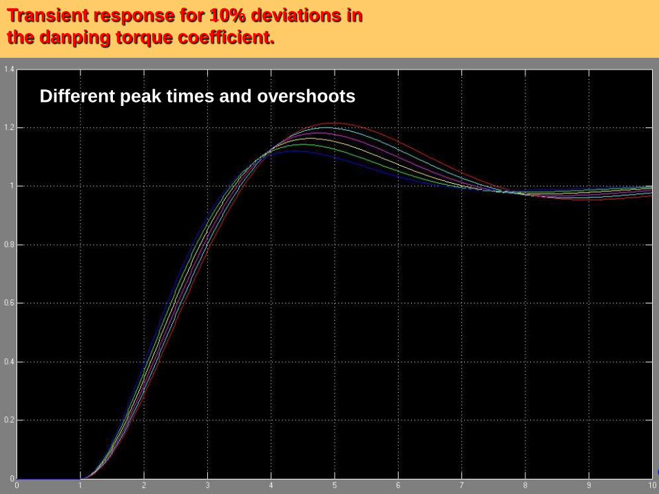
Transient response for 10% deviations in
the danping torque coefficient.
Different peak times and overshoots


![[ZINE] Ocupa Reitoria UFRGS](https://img.pdfslide.us/doc/110x75/57906eca1a28ab687495ea9b/zine-ocupa-reitoria-ufrgs.jpg)