Embed Size (px)
Citation preview
7/31/2019 WF Integration Through MTDC-VSC
http://slidepdf.com/reader/full/wf-integration-through-mtdc-vsc 1/7
1
Abstract —This paper presents a large off shore wind farm
interconnected to the grid using a multiterminal HVDC link. The
200W wind farm consists of 100 individual 2MW turbines
connected using 25 VSC (Voltage Source Converter) converters
to a common DC bus. The transmission system converters enable
variable speed operation and therefore additional converters are
not needed with individual generators, implying savings in
converter costs.
The paper presents PSCAD simulation of the proposed
concept for various changes in wind speeds. The results confirm
the ability to operate at optimum coefficient of performance and
no synchronization problems occur even for severe wind speed
changes. Further tests with faults on AC grid demonstrate
satisfactory recoveries. The proposed concept may enable
integration of large offshore wind farms at considerable
distances, and using optimal number of converters.
Index Terms — Multiterminal HVDC Power Transmission,
Wind farms, Variable speed converter control.
I. I NTRODUCTION
A. Background
ecause of the projected energy shortage and the concerns
about greenhouse emissions, there has been significant
development in renewable energy sources worldwide, in
the past decade. In particular, the UK government aims to
achieve the goal of 20% (up to 40% in Scotland) energyproduction from renewable sources by 2020. It is projected
that the increase in renewable energy share from the present
3% will be largely based on increase in wind energy
generation, which is likely to become the main source of
renewable energy in the UK and in many other countries.
Because of the economy of scale and increasing demand,
future wind farms will have a larger capacity, exceeding a
hundred MW in many cases, implying hundreds of individual
1-5MW units. Considering also the environmental issues, it is
recognized that large size offshore wind farms are the well
placed to accommodate the future increase in the wind energy
generation [1-2]. Presently, there are a number of small-scale
offshore wind farms in Europe, including several in the UK,where the largest is the (160MW ) farm at Horns Rev,
Denmark. Under the “Round two” offshore program, the
British government has recently granted permission for fifteen
more off-shore plants, and many of these are expected to be
rated at 100-500MW . Because of the environmental and social
aspects these wind farms might be located at larger distances,
some approaching 100-150km from the shore [1].
D. Jovcic is with University of Aberdeen, Engineering Department, King’s
college, Aberdeen, AB24 3UE, Scotland. [email protected]
Traditionally, wind energy generation has been
connected to the network grid assuming that its size and
influence are small and therefore the connection requirements
have been less stringent. Typically, wind farms do not
contribute stabilization or regulation of AC grid and in many
cases no detailed transient studies or stability studies are
performed. With the projected power injection in the order of
hundreds of MW, power plants might have significant
influence on the host grid and the interaction issues need to be
carefully investigated. New integration solutions are sought,
taking into consideration the AC system properties including
stabilization, regulation and fault recovery, but also examining
cost effective wind farm topologies, their dynamics, transientsand efficiency.
At present, none of the wind farms, including the large
Horns Rev offshore installation, can contribute to the AC
system control or stability enhancement and they simply
disconnect in case of AC faults. As the power share from wind
farms increase, it is necessary that wind farms should take
more active role in the AC systems regulation and support.
The network operators have raised many issues with wind
power generation, especially for large-scale generation, in
order to enable secure and reliable system operation. The
Danish network operator Eltra, has recently issued a unique
specifications document for wind farms connections to the
transmission grid [3], and comparable documents are inconsultation stages in England, Wales and Scotland. Similarly
as with conventional generators, wind farms are now required
to comply with stringent connection requirements including:
reactive power support, transient recovery, system stability
and voltage/frequency regulation, power quality, whereas
scheduling and reserve availability are also considered. The
conventional wind generation concepts based on doubly fed
induction generators may have difficulties in meeting all the
above interconnection requirements [2].
B. Wind farm interconnection using HVDC
Theoretically, future offshore wind farms at distances
below 60km from the shore can be connected to the grid using
either an AC or DC link whereas at a greater distance only DC
links are applicable [1]. In searching for the adequate wind
energy integration solution, it has been recognized that many
of the above network-connection issues would be eliminated,
and even AC system stability might be enhanced, if the wind
power connection point incorporates a converter system [2].
AC connection link would therefore in many cases require an
additional converter system (like SVC or STATCOM) at the
connection point for reactive power and voltage support. Still,
this shunt converter does not resolve the issues with low
inertia, power control and frequency control/stabilization of
Interconnecting offshore wind farms using
multiterminal VSC-based HVDCD. Jovcic, Member IEEE
B
1-4244-0493-2/06/$20.00 ©2006 IEEE.

7/31/2019 WF Integration Through MTDC-VSC
http://slidepdf.com/reader/full/wf-integration-through-mtdc-vsc 2/7
2
the AC system, which remain significant issue with large wind
farms.
Traditional HVDC controls have in many cases been used
for AC frequency stabilization [6] or AC voltage regulation.
HVDC systems based on VSC converters have more versatile
and faster controls [4],[5], which may be utilized at the wind
farm interconnection point. A VSC converter enables
independent voltage, frequency and power control. A wind
farm interconnected with an HVDC link therefore has the
potential to offer grid control functions similar to a
conventional generator. On the downside, cost of HVDC link
is considerably higher than comparable AC link because of
converter stations.
This paper analyses the option of reducing converter costs
by eliminating primary converter systems associated with
common variable speed wind generators. Such concept has the
potential to offer variable speed operation and all the benefits
of HVDC interconnection without significant escalation in
converter costs.
II. WIND FARM TOPOLOGY
Figure 1 shows the electrical circuit for the considered windfarm. It presents a 200MW off shore wind farm consisting of
100 individual 2MW , 4kV wind generators. It is assumed that
the farm distance from the shore is approximately 100km.
The wind generators resemble the commercially available
2MW units based on permanent magnet synchronous
generators. However, converter systems are not used with
generators, since transmission system converters enable
variable speed operation. This concept implies savings in the
converter costs. The total converter rating in Figure 1 is same
as with conventional fully-fed variable speed wind generators
and Ac interconnection.
The nominal operating frequency of the offshore network is
50Hz (at full power), and the 4-pole generators use gearboxes
(approximately 77 ratio). Note that directly coupled generators
are not suitable in the proposed concept since they would
require operation at very low offshore electrical frequency and
therefore transformers with large cores would be needed.
The offshore electrical network consists of 25 generator groups each connected through a single Voltage Source
Converter (VSC). Each 8MW group includes 4 generators.
There is a single 4kV/90kV transformer per group, which
elevates the generator voltage to the transmission level.
The wind turbines operate at variable speeds in order to
maximize energy capture, reduce stresses and reduce noise.
The generator speed is controlled using the VSC converters,
and all the generators in a group operate at the same speed.
The frequency in a group, and the speed of all generators in
the group, is derived as the average speed considering wind
speeds at individual machines. The inability to operate
individual machines at most optimum speeds is not considered
as great loss in efficiency, since it is expected that the wind
profile will largely be similar on the four closely located
turbines. Note that each group can operate at most suitable
speed, which is independent of speeds for other groups.
The 25 VSC converters are connected in parallel to a
common DC bus, thus operating at the same DC voltage in a
parallel multiterminal HVDC connection. The DC voltage is
maintained at the nominal level (150kV ) by the single VSC
inverter located on-shore.
AC Network on shore SCL=10
+75kV +75kV 0.0135H 0.0135H
0.052H
110kV
110kV
90kV/110kV
Xl=10%
1.85Ω 1.85Ω
4.36Ω
-75kV -75kV
200MW
150kV
100kM DC cable
25 VSC
converters
VSC - Voltage Source Converter
VSC 1
G (2MW)4kV
4kV
4kV/90kV
Xl=12% 8MW
150kV
4
s y n c h r o n o u s g e
n e r a t o r s
∆ Y
VSC 25
G (2MW)4kV
4kV
4kV/90kV
Xl=12% 8MW
4
s y n c h r o n o u s g e n e r a t o
r s
∆
∆
Y
Y
80uF120uF
120uF
34uF
80uF
Figure 1. 200MW off-shore wind farm with parallel multiterminal HVDC connection

7/31/2019 WF Integration Through MTDC-VSC
http://slidepdf.com/reader/full/wf-integration-through-mtdc-vsc 3/7
3
III. WIND FARM MODEL
A. Electrical circuit
A suitable model for the system in Figure 1 is developed on
PSCAD/EMTDC platform [7]. It would be extremely difficult
to model such complex system in detail, and a series of
simplifications is adopted.
The schematic of the PSCAD model is shown in Figure 2.The number of the off-shore converters is reduced to four in
order to save simulation time. The converters are rated 50MW
and they are connected in parallel to represent multiterminal
HVDC operation in the actual system. Only one of the
converters is connected to four machines, to enable studies of
the dynamics within a group.
All the machines models are based on a single 2MW
permanent magnet synchronous machine, which has common
parameters from PSCAD library. The large 50MW generators
are also based on the same 2MW machine model, which uses
PSCAD ability to represent 25 coherent 2MW machines in a
single model.
B. Offshore VSC controller
The adopted principle of a parallel multiterminal HVDC
control is explained with reference to Figure 3. The inverter
station regulates the DC voltage which is common for all
converter stations. Each of the rectifier stations (the offshore
converters) regulates the DC current in its own branch.
The generator speed control can be achieved using the
known principles of flux oriented synchronous machine
control and using position encoder to synchronize the
coordinate frame [8]. However, since a transformer is placed
between machine and converter, it is found more suitable to
use the torque control based on regulation of power transfer
through the transformer. The rotating coordinate frame
position is determined using a PLL, which measures the 4kV
generator voltage. This signal is a good estimate of the rotor
position and therefore the danger of loss of machine
synchronism is avoided.
The control system for each of the offshore converters is
shown in Figure 4. The machine power, and consequently
machine torque, is varied by changing the angle of the VSCconverter voltage M Φ, with respect to the generator terminal
voltage. The power control in VSC transmission is commonly
achieved either using the VSC voltage angle or VSC voltage
D component [9-11]. As shown by the lower control diagram
in Figure 4, the VSC angle control is based on two series
connected controllers. The inner control loop regulates the DC
current (in the concerned DC branch) which improves
performance of the of the outer speed control loop. The inner
DC current loop also prevents overcurrents in the DC system.
The generator speed operating range is approximately
65rad/s<w g <158rad/s, corresponding to the off-shore grid
frequency 20Hz<f s<50Hz, and corresponding to the wind
speed range at optimal c p
5m/s<vw<12m/s. The actual allowed
wind speed range is wider, but the operation beyond these
limits is at lower coefficient of performance.
The reference generator speed w gref is calculated to enable
maximum coefficient of performance as [12]:
2
P g
r
k vw r
r
tsw gref = (1)
Where vw is the wind speed, k ts is the optimal tip speed ratio
(typically k ts=7 ), g r =77 , is the gearbox ratio, P=4 is the
number of generator poles and r r =41m is the turbine radius.
AC Network on shore SCL=10
++75kV 0.0135H 0.0135H
0.052H
110kV
110kV
90kV/110kV
Xl=10%
1.85Ω 1.85Ω
4.36Ω
-75kV -75kV
200MW
150kV
100kM DC cable
VSC - Voltage Source Converter
VSC 1
VSC 2
VSC 3
VSC I
4kV/90kV
Xl=12%
4kV/90kV
Xl=12%
4kV/90kV
Xl=12%
50MW
150kV
50MW
150kV
50MW
150kV
56MW
150kV
∆
∆
∆
Y
Y
Y
VSC 4
G41 (14MW)
G42 (14MW)
G43 (14MW)
G44 (14MW)
G1 (50MW)
G2 (50MW)
G3 (50MW)
4kV
4kV/90kV
Xl=12%
4
s y n c h r o n o u s g e n e r a t o r s
∆
∆
Y
Y
80uF120uF
120uF
34uF
80uF
Figure 2. Simulation model for the test system.
7/31/2019 WF Integration Through MTDC-VSC
http://slidepdf.com/reader/full/wf-integration-through-mtdc-vsc 4/7
4
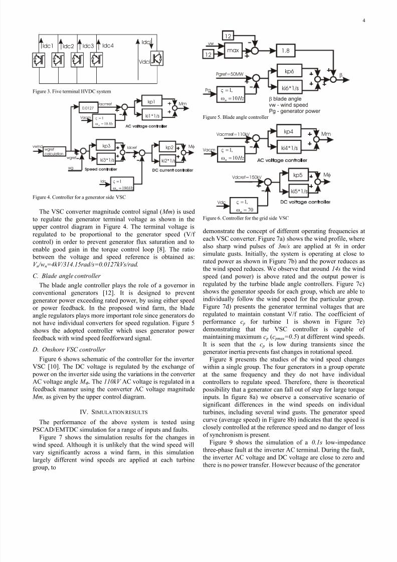
Idc1 Idc2 Idc3 Idc4
Vdci
Idci
Figure 3. Five terminal HVDC system
ki1*1/s
kp1 Vacmref
Vacm
0.0127Mm
ki2*1/s
kp2Idcref
wgref
wgref
calculation
vwind
Idc
wg
Mφ
ki3*1/s
kp3
Hz n
180
1
=
=
ω
ς
Hz n
10
1
=
=
ω
ς
Figure 4. Controller for a generator side VSC
The VSC converter magnitude control signal ( Mm) is used
to regulate the generator terminal voltage as shown in the
upper control diagram in Figure 4. The terminal voltage is
regulated to be proportional to the generator speed (V/f
control) in order to prevent generator flux saturation and to
enable good gain in the torque control loop [8]. The ratio
between the voltage and speed reference is obtained as:
V n /wn=4kV/314.15rad/s=0.0127kVs/rad .
C. Blade angle controller
The blade angle controller plays the role of a governor in
conventional generators [12]. It is designed to preventgenerator power exceeding rated power, by using either speed
or power feedback. In the proposed wind farm, the blade
angle regulators plays more important role since generators do
not have individual converters for speed regulation. Figure 5
shows the adopted controller which uses generator power
feedback with wind speed feedforward signal.
D. Onshore VSC controller
Figure 6 shows schematic of the controller for the inverter
VSC [10]. The DC voltage is regulated by the exchange of
power on the inverter side using the variations in the converter
AC voltage angle M Φ. The 110kV AC voltage is regulated in a
feedback manner using the converter AC voltage magnitude
Mm, as given by the upper control diagram.
IV. SIMULATION RESULTS
The performance of the above system is tested using
PSCAD/EMTDC simulation for a range of inputs and faults.
Figure 7 shows the simulation results for the changes in
wind speed. Although it is unlikely that the wind speed will
vary significantly across a wind farm, in this simulation
largely different wind speeds are applied at each turbine
group, to
ki6*1/s
kp6
1.812
12
max
Pgref=50MW
Pg
vw
β
β blade anglevw - wind speedPg - generator power
Hz n 10
,1
=
=
ω
ς
Figure 5. Blade angle controller
ki4*1/s
kp4 Vacmref=110kV
Vacm
Mm
ki5*1/s
kp5 Vdcref=150kV
Vdc
Mφ
70
,1
=
=
nω
ς
Hz n
10
,1
=
=
ω
ς
Figure 6. Controller for the grid side VSC
demonstrate the concept of different operating frequencies at
each VSC converter. Figure 7a) shows the wind profile, where
also sharp wind pulses of 3m/s are applied at 9s in order
simulate gusts. Initially, the system is operating at close to
rated power as shown in Figure 7b) and the power reduces as
the wind speed reduces. We observe that around 14s the wind
speed (and power) is above rated and the output power is
regulated by the turbine blade angle controllers. Figure 7c)
shows the generator speeds for each group, which are able to
individually follow the wind speed for the particular group.
Figure 7d) presents the generator terminal voltages that are
regulated to maintain constant V/f ratio. The coefficient of
performance c p for turbine 1 is shown in Figure 7e)
demonstrating that the VSC controller is capable of
maintaining maximum c p (c pmax=0.5) at different wind speeds.
It is seen that the c p is low during transients since the
generator inertia prevents fast changes in rotational speed.
Figure 8 presents the studies of the wind speed changes
within a single group. The four generators in a group operate
at the same frequency and they do not have individual
controllers to regulate speed. Therefore, there is theoretical
possibility that a generator can fall out of step for large torque
inputs. In figure 8a) we observe a conservative scenario of
significant differences in the wind speeds on individual
turbines, including several wind gusts. The generator speed
curve (average speed) in Figure 8b) indicates that the speed is
closely controlled at the reference speed and no danger of loss
of synchronism is present.
Figure 9 shows the simulation of a 0.1s low-impedance
three-phase fault at the inverter AC terminal. During the fault,
the inverter AC voltage and DC voltage are close to zero and
there is no power transfer. However because of the generator
7/31/2019 WF Integration Through MTDC-VSC
http://slidepdf.com/reader/full/wf-integration-through-mtdc-vsc 5/7
5
Pg1
Pg4
Pg3
Pdcinv
wgen1 wgen4
wgen2
wgen3
vw1
vw4
vw3
vw2
Vg4
Vg1 Vg2
Vg3
a)
b)
c)
d)
wind gusts
e)
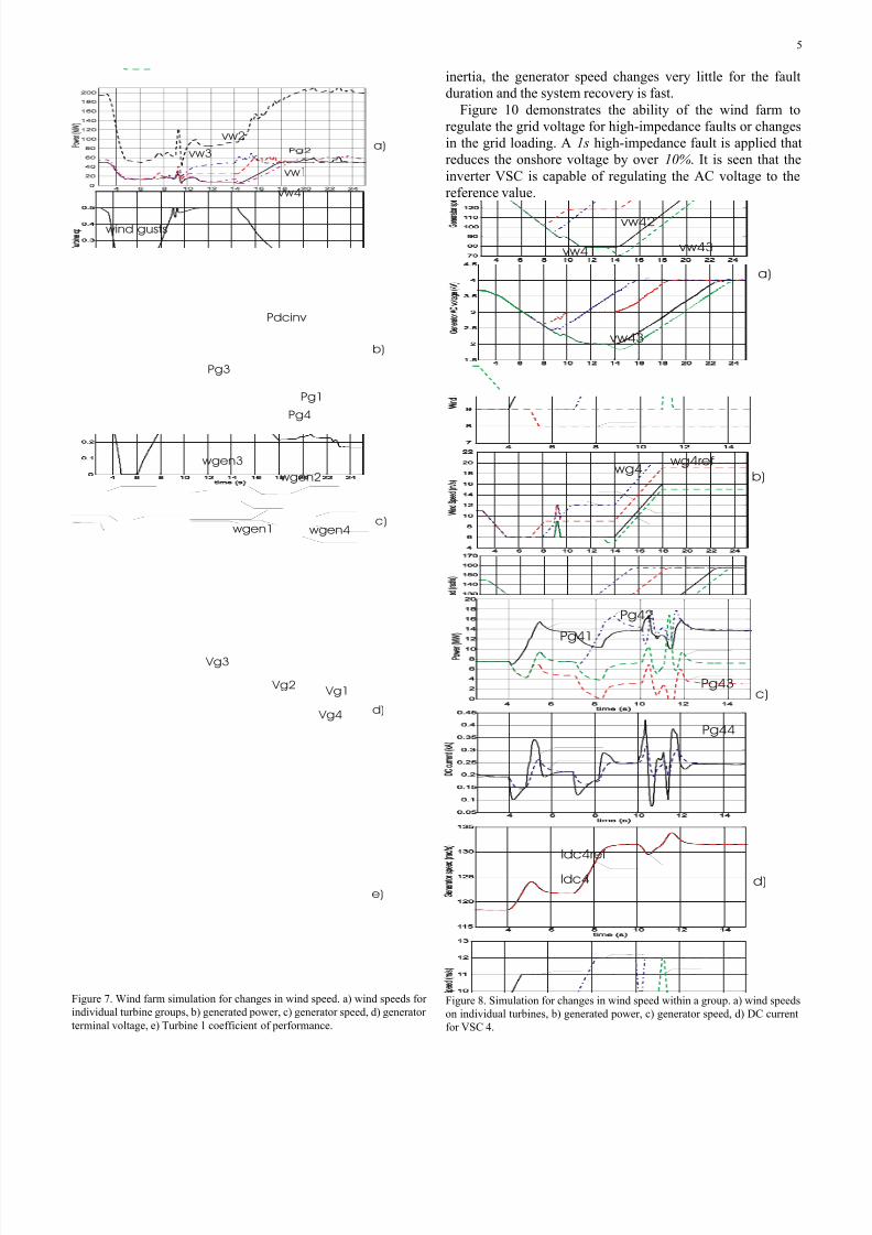
Figure 7. Wind farm simulation for changes in wind speed. a) wind speeds for
individual turbine groups, b) generated power, c) generator speed, d) generator
terminal voltage, e) Turbine 1 coefficient of performance.
inertia, the generator speed changes very little for the fault
duration and the system recovery is fast.
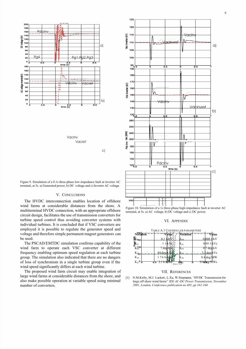
Figure 10 demonstrates the ability of the wind farm to
regulate the grid voltage for high-impedance faults or changes
in the grid loading. A 1s high-impedance fault is applied that
reduces the onshore voltage by over 10%. It is seen that the
inverter VSC is capable of regulating the AC voltage to the
reference value.
Pg41
Pg42
Pg43
Pg44
Idc4
Idc4ref
vw41
vw42
vw43
vw43
a)
b)
c)
d)
wg4wg4ref
Figure 8. Simulation for changes in wind speed within a group. a) wind speeds
on individual turbines, b) generated power, c) generator speed, d) DC current
for VSC 4.
7/31/2019 WF Integration Through MTDC-VSC
http://slidepdf.com/reader/full/wf-integration-through-mtdc-vsc 6/7
6
Pdcinv
Pg4 Pg1,Pg2,Pg3
Vdcinv Vdcref
Vacinv
Vacref
a)
b)
c)
Figure 9. Simulation of a 0.1s three-phase low-impedance fault at inverter ACterminal, at 5s. a) Generated power, b) DC voltage and c) Inverter AC voltage.
V. CONCLUSIONS
The HVDC interconnection enables location of offshore
wind farms at considerable distances from the shore. A
multiterminal HVDC connection, with an appropriate offshore
circuit design, facilitates the use of transmission converters for
turbine speed control thus avoiding converter systems with
individual turbines. It is concluded that if VSC converters are
employed it is possible to regulate the generator speed and
voltage and therefore simple permanent magnet generators can
be used.
The PSCAD/EMTDC simulation confirms capability of thewind farm to operate each VSC converter at different
frequency enabling optimum speed regulation at each turbine
group. The simulation also indicated that there are no dangers
of loss of synchronism in a single turbine group even if the
wind speed significantly differs at each wind turbine.
The proposed wind farm circuit may enable integration of
large wind farms at considerable distances from the shore, and
also make possible operation at variable speed using minimal
number of converters.
Vacinv
Vacinvref
Vdcinv
Vdcinvref
Pdcinv
a)
b)
c)
Figure 10. Simulation of a 1s three-phase high-impedance fault at inverter AC
terminal, at 5s. a) AC voltage, b) DC voltage and c) DC power.
VI. APPENDIX
TABLE A.1 CONTROLLER PARAMETERS
Notation Value Notation Value
K P1 0.1 1/kV K P4 0.008 1/kV
K I1 1 1/kVs K I4 0.05 1/kVsK P2 7 deg/kA K P5 0.7 deg/kV
K I2 80 deg/kAs K I5 2.5 deg/kVs
K P3 1.2 kAs/rad K P6 0.4 deg/MW
K I3 2.1 kA/rad K I6 0.8 deg/MWs
VII. R EFERENCES
[1] N.M.Kirby, M.J. Luckett, L.Xu, W.Siepmann, “HVDC Transmission for
large off shore wind farms” IEE AC-DC Power Transmission, November
2001, London, Conference publication no 485, pp 162-168.
7/31/2019 WF Integration Through MTDC-VSC
http://slidepdf.com/reader/full/wf-integration-through-mtdc-vsc 7/7
7
[2] L.Holdsworth, N.Jenkins, G.Strbac “Electrical Stability of Large,
Offshore Wind Farms. IEE AC-DC Power Transmission, November
2001, London, Conference publication no 485, pp 156-161.
[3] Eltra, Transmission Systems Planning “Specifications for Connecting
Wind Farm to Transmission Networks” document no 74557, Eltra
Denmark, 2000, http://www.eltra.dk
[4] Kjell Ericsson "Operational Experience of HVDC Light" Seventh
International Conference on AC-DC Power Transmission. IEE. 2001,
pp.205-210. London, UK .
[5] B R Andersen, L Xu, K T G Wong, “Topologies for VSC transmission,”
Seventh International Conference on AC-DC Power Transmission (IEE
Conf. Publ. No.485). IEE. 2001, pp.298-304. London, UK .
[6] C.E.Grund at all. “Dynamic performance characteristics of North
American HVDC Systems for transient and dynamic stability
evaluations” IEEE Transactions on PAS-100, no 7, 1981, pp3356-3364
[7] Manitoba HVDC Research Centre, “PSCAD/EMTDC User Manual,”
Tutorial Manual, 1994.
[8] B.K. Bose “Modern Power Electronics and AC drives” Prentice Hall
2002
[9] B. Ooi, Xiao Wang, “Voltage Angle Lock Loop control of the boost type
PWM converter for HVDC application,” IEEE Trans. on power
electronics, vol 5 no 2, April 1990, Pp 229-235.
[10] D. Jovcic L.A.Lamont, L.Xu: “VSC Transmission model for analytical
studies" Power Engineering Society General Meeting, 2003, IEEE,
Volume: 3, 13-17 July 2003, Pages:1737 - 1742
[11] J L Thomas, S Poullain, A Benchaib, “Analysis of a robust DC-bus
voltage control system for a VSC transmission scheme,” Seventh
International Conference on AC-DC Power Transmission IEE. 2001, pp.119-24. London, UK .
[12] S. Hier, Grid Integration of Wind Energy Conversion Systems, John
Wiley and Sons 1998.
VIII. BIOGRAPHY
Dragan Jovcic (S’97, M’00) obtained a B.Sc. in Control Engineering from
the University of Belgrade, Yugoslavia in 1993 and a Ph.D. degree in
Electrical Engineering from the University of Auckland, New Zealand in
1999.
He is currently a lecturer with the University of Aberdeen, Scotland where
he has been since 2004. He also worked as a lecturer with University of
Ulster, in period 2000-2004 and as a design Engineer in the New Zealand
power industry in period 1999-2000. His research interests lie in the areas of
FACTS, HVDC and control systems.


![Laboratory Demonstration of a Multiterminal VSC-HVDC Power ... · the point-to-point links to finally obtain Multi-Terminal Direct Current (MTDC) systems [7], [8]. In fact, aggregating](https://img.pdfslide.us/doc/110x75/5fd923be3b75e87ba303354a/laboratory-demonstration-of-a-multiterminal-vsc-hvdc-power-the-point-to-point.jpg)