Embed Size (px)
Citation preview
Rev. 5/12/98
Frank E. Van LareWastewater Treatment Plant
Wet WeatherOperating Guidelines
May 1998
TABLE OF CONTENTS
Section 1 IntroductionSection 2 Control RoomSection 3 Samples and SamplerSection 4 Flow MetersSection 5 Process WaterSection 6 Control Structure 46Section 7 Grit Handling BuildingSection 8 Screening and Aerated Grit Facility (AGF)Section 9 N Tanks (East Primaries) and DistributionSection 10 P’s (West Primaries)Section 11 Split FlowSection 12 Aeration and Distribution StructuresSection 13 RecirculationSection 14 Final Clarifier and DistributionSection 15 ChlorinationSection 16 66-Inch Diversion GateSection 17 NAG and Hypo/120Section 18 ATF ScreenSection 19 Culver-Goodman Control StructureSection 20 Control Structure 44Section 21 Control Structure 45Section 22 Jewel StreetSection 23 Glenwood Avenue ScreenhouseSection 24 Cliff Street ScreenhouseSection 25 Genesee River Interceptor - Shaft No. 1Section 26 Irondequoit Shaft No. 5 (Formerly Thomas Street)Section 27 CIPS (Irondequoit Pump Station)Section 28 Structure 243Section 29 Influent DistributionSection 30 Front Street DiversionSection 31 Malvern Street Diversion

Section 32 Densmore DiversionSection 33 Glossary
Frank E. Van Lare Wastewater Treatment PlantWet Weather Operating Guidelines
1-1 Rev. 5/12/98
SECTION 1 - INTRODUCTION
1.1 Background
This manual contains wet weather operating guidelines for Monroe County’s Frank E. Van LareWastewater Treatment Plant and the wastewater and stormwater collection system serving the plant. TheVan Lare plant serves the City of Rochester and other Monroe County communities, providing preliminary,primary, and secondary treatment to all dry weather wastewater flow entering the sewer system. Thewastewater collection system is a combined sewer system which collects both wastewater and stormwater. During wet weather events, when stormwater flows enter the combined sewer system, overflows can occurat combined sewer overflows which discharge to the Genesee River, Irondequoit Bay, Lake Ontario, ortheir tributaries.
Monroe County has installed an extensive tunnel system to store combined stormwater and wastewaterduring wet weather events. The Combined Sewer Overflow Abatement Program (CSOAP) tunnel systemwas designed and built with several objectives in mind:
1. The first objective was to intercept any combination of sewer overflows that negatively impactthe area’s bodies of water.
2. The second objective was to provide storage for the intercepted flows and diminish the amountof uncontrolled flows that impact the Van Lare treatment plant. The ultimate goal is to storethe flow until the plant is capable of giving the incoming flow the proper treatment before it isdischarged to the lake.
3. The third objective was to provide in-line relief for some of the larger diameter surface sewers. This would help maintain capacity and prevent sewer backups in property basements.
Following a wet weather event, combined sewage is removed from the tunnels and sent to the Van Lareplant for treatment. The tunnel system has significantly reduced the frequency and volume of combinedsewer overflows and has had a beneficial environmental impact on the area’s surface waters.
The plant’s NPDES discharge permit requires that flows up to 135 mgd receive full secondary treatment. Flows between 135 and 200 mgd may receive primary treatment and disinfection prior to discharge toLake Ontario. This mode of operation is referred to as “split flow” by the plant staff. Flows in excess of200 mgd can be sent to the Additional Treatment Facility (ATF) where they receive preliminary treatmentconsisting of screening and grit removal prior to discharge to the lake through the 120-inch outfall pipe. This
Frank E. Van Lare Wastewater Treatment PlantWet Weather Operating Guidelines
SECTION 1 (Continued):
1-2 Rev. 5/12/98
operational mode is called “120 flow” by the plant staff. Total flow to the Van Lare plant can exceed 600mgd during extreme wet weather events.
1.2 Performance Goals for Wet Weather Events
Many potential choices exist for handling flows and treatment processes during wet weather events. TheCounty and NYSDEC have established a set of prioritized goals for protection of the County’s receivingwaters. The primary goals for protection of receiving waters during high flow storm events are divided intothree groups:
1. Highest Priority - Protect Irondequoit Bay.
a. Prevent overflows at Browncroft which relieves the Irondequoit Tunnel (i.e., IBPS).b. Prevent overflows from the Culver-Goodman Tunnel.c. Prevent overflows at the Densmore Creek Control Structure.d. Prevent overflows at the Thomas Creek Control Structure.
2. Second Priority - Protect the Genesee River. Maximize flows to the plant as early aspossible to avoid overflows at Structures 243, 45, and 44.
3. Third Priority - Protect Lake Ontario. Maximize flows in an orderly fashion to preventsolids loss from the secondary clarifiers.
1.3 Purpose of This Manual
The purpose of this manual is to provide a set of operating guidelines to assist the Van Lare plant andcollection/tunnel system staff in making operational decisions which will best meet the performance goalsstated in Section 1.2 and the requirements of the NPDES discharge permit.
During a wet weather event, numerous operational decisions must be made to effectively manage storageof stormwater in the tunnel system and optimize wastewater treatment at the Van Lare plant. Storage iscontrolled through adjustment of gates at control structures in the collection/tunnel system. Flow rates atwhich “split flow” or “120 flow” are initiated depend upon a complex set of factors, including presentconditions within specific treatment processes (such as sludge settling characteristics) and anticipated stormduration. Each new storm event provides new situations and new combination flow patterns and plantconditions. No manual can describe the decision making process for every possible wet weather scenariowhich will be encountered at Van Lare. This manual can, however, serve as a useful reference which bothnew and experienced operators can utilize during wet weather events. The manual can be useful in
Frank E. Van Lare Wastewater Treatment PlantWet Weather Operating Guidelines
SECTION 1 (Continued):
1-3 Rev. 5/12/98
preparing for a coming wet weather event, a source of ideas for controlling specific processes during thestorm, and a checklist to avoid missing critical steps in monitoring and controlling processes during wetweather.
1.4 Using This Manual
This manual is designed to allow use as a quick reference during wet weather events. It is broken downinto sections which cover major unit processes at the Van Lare plant or major controls points in the plant,tunnels, or collection system. Each section is provided with a tab for easy access. Each section includesthe following information:
• list of unit processes and equipment covered in this section• steps to take before a wet weather event and who is responsible for these steps• steps to take during a wet weather event and who is responsible for these steps• steps to take after a wet weather event and who is responsible for these steps• discussion of why the recommended control steps are performed• identification of specific circumstances that trigger the recommended changes• identification of things that can go wrong with the process
Sections on control structures in the collection/tunnel system include maps showing the control structurelocation and diagrams showing critical control elevations in the structure.
This manual is a living document. Users of the manual are encouraged to identify new steps, procedures,and recommendations to add to the descriptions contained herein. Modifications which improve upon themanual’s procedures are also encouraged. If you have a suggestion for modifications or additions to themanual, mark them on copies of the affected pages and submit them to your supervisor, so they can beconsidered for insertion in the manual. With continued input from all users of the manual, it will become aneven more useful and effective tool.
1.5 Acknowledgments
The content of this manual was developed by staff from the Van Lare plant and the collection/tunnel systemduring 1997. Through a series of group meetings, these wet weather operating guidelines were drafted,reviewed and finalized. Special thanks go to Bob Hamilton, Herm Thein, Dave Lukas, Dan Ross, DougAlaimo, John Wurzbacher, Glenn Curtis, Sean Murphy, John Fiutko, Scott McEntee, Bob Salata, JimHetzer, and John Debelis for their input into this manual. Thanks also to Brandon Chew and Phil Smith ofNYSDEC Facilities Operations Assistance for their efforts in facilitating preparation of this manual.
Frank E. Van Lare Wastewater Treatment PlantWet Weather Operating Guidelines
2-1 Rev. 5/12/98
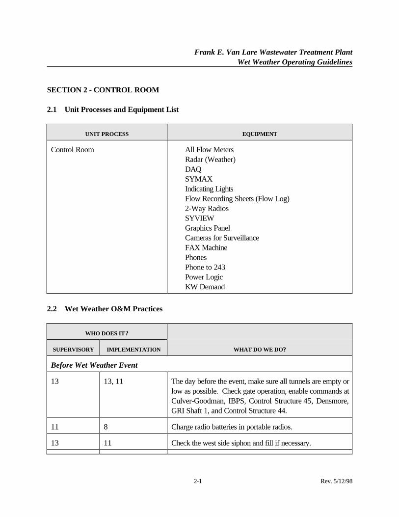
SECTION 2 - CONTROL ROOM
2.1 Unit Processes and Equipment List
UNIT PROCESS EQUIPMENT
Control Room ⋅ All Flow Meters⋅ Radar (Weather)⋅ DAQ⋅ SYMAX⋅ Indicating Lights⋅ Flow Recording Sheets (Flow Log)⋅ 2-Way Radios⋅ SYVIEW⋅ Graphics Panel⋅ Cameras for Surveillance⋅ FAX Machine⋅ Phones⋅ Phone to 243⋅ Power Logic⋅ KW Demand
2.2 Wet Weather O&M Practices
WHO DOES IT?
SUPERVISORY IMPLEMENTATION WHAT DO WE DO?
Before Wet Weather Event
13 13, 11 The day before the event, make sure all tunnels are empty orlow as possible. Check gate operation, enable commands atCulver-Goodman, IBPS, Control Structure 45, Densmore,GRI Shaft 1, and Control Structure 44.
11 8 Charge radio batteries in portable radios.
13 11 Check the west side siphon and fill if necessary.
Frank E. Van Lare Wastewater Treatment PlantWet Weather Operating Guidelines
2-2 Rev. 5/12/98
WHO DOES IT?
SUPERVISORY IMPLEMENTATION WHAT DO WE DO?
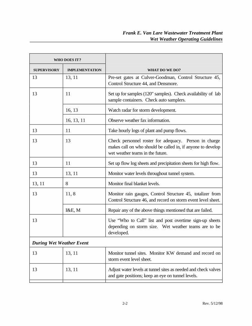
13 13, 11 Pre-set gates at Culver-Goodman, Control Structure 45,Control Structure 44, and Densmore.
11 Set up for samples (120" samples). Check availability of labsample containers. Check auto samplers.
16, 13 Watch radar for storm development.
13
16, 13, 11 Observe weather fax information.
13 11 Take hourly logs of plant and pump flows.
13 13 Check personnel roster for adequacy. Person in chargemakes call on who should be called in, if anyone to developwet weather teams in the future.
13 11 Set up flow log sheets and precipitation sheets for high flow.
13 13, 11 Monitor water levels throughout tunnel system.
13, 11 8 Monitor final blanket levels.
11, 8 Monitor rain gauges, Control Structure 45, totalizer fromControl Structure 46, and record on storm event level sheet.
13
I&E, M Repair any of the above things mentioned that are failed.
13 Use “Who to Call” list and post overtime sign-up sheetsdepending on storm size. Wet weather teams are to bedeveloped.
During Wet Weather Event
13 13, 11 Monitor tunnel sites. Monitor KW demand and record onstorm event level sheet.
13 13, 11 Adjust water levels at tunnel sites as needed and check valvesand gate positions; keep an eye on tunnel levels.
Frank E. Van Lare Wastewater Treatment PlantWet Weather Operating Guidelines
2-3 Rev. 5/12/98
WHO DOES IT?
SUPERVISORY IMPLEMENTATION WHAT DO WE DO?
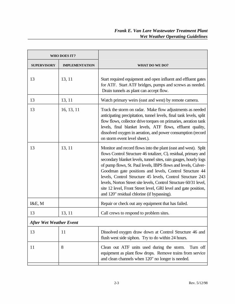
13 13, 11 Start required equipment and open influent and effluent gatesfor ATF. Start ATF bridges, pumps and screws as needed. Drain tunnels as plant can accept flow.
13 13, 11 Watch primary weirs (east and west) by remote camera.
13 16, 13, 11 Track the storm on radar. Make flow adjustments as neededanticipating precipitation, tunnel levels, final tank levels, splitflow flows, collector drive torques on primaries, aeration tanklevels, final blanket levels, ATF flows, effluent quality,dissolved oxygen in aeration, and power consumption (recordon storm event level sheet.).
13 13, 11 Monitor and record flows into the plant (east and west). Splitflows Control Structure 46 totalizer, Cl2 residual, primary andsecondary blanket levels, tunnel sites, rain gauges, hourly logsof pump flows, St. Paul levels, IBPS flows and levels, Culver-Goodman gate positions and levels, Control Structure 44levels, Control Structure 45 levels, Control Structure 243levels, Norton Street site levels, Control Structure 60/31 level,site 12 level, Front Street level, GRI level and gate position,and 120" residual chlorine (if bypassing).
I&E, M Repair or check out any equipment that has failed.
13 13, 11 Call crews to respond to problem sites.
After Wet Weather Event
13 11 Dissolved oxygen draw down at Control Structure 46 andflush west side siphon. Try to do within 24 hours.
11 8 Clean out ATF units used during the storm. Turn offequipment as plant flow drops. Remove trains from serviceand clean channels when 120" no longer is needed.
Frank E. Van Lare Wastewater Treatment PlantWet Weather Operating Guidelines
2-4 Rev. 5/12/98
WHO DOES IT?
SUPERVISORY IMPLEMENTATION WHAT DO WE DO?
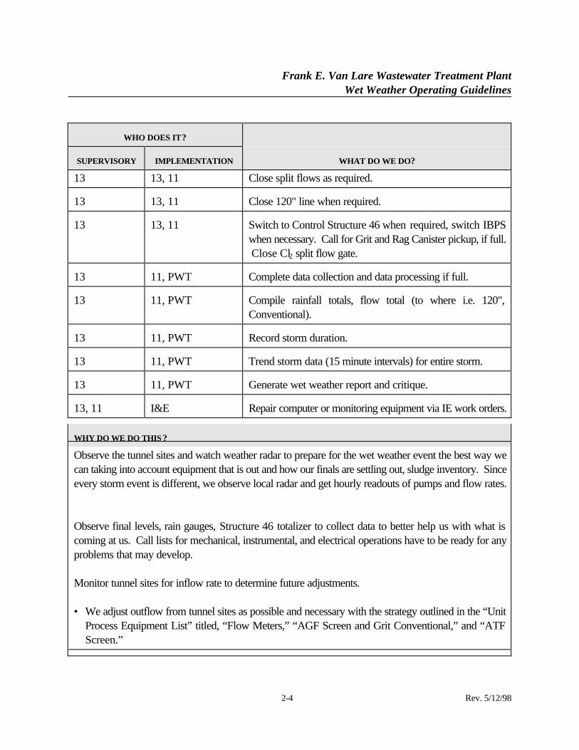
13 13, 11 Close split flows as required.
13 13, 11 Close 120" line when required.
13 13, 11 Switch to Control Structure 46 when required, switch IBPSwhen necessary. Call for Grit and Rag Canister pickup, if full. Close Cl2 split flow gate.
13 11, PWT Complete data collection and data processing if full.
13 11, PWT Compile rainfall totals, flow total (to where i.e. 120",Conventional).
13 11, PWT Record storm duration.
13 11, PWT Trend storm data (15 minute intervals) for entire storm.
13 11, PWT Generate wet weather report and critique.
13, 11 I&E Repair computer or monitoring equipment via IE work orders.
WHY DO WE DO THIS ?
Observe the tunnel sites and watch weather radar to prepare for the wet weather event the best way wecan taking into account equipment that is out and how our finals are settling out, sludge inventory. Sinceevery storm event is different, we observe local radar and get hourly readouts of pumps and flow rates.
Observe final levels, rain gauges, Structure 46 totalizer to collect data to better help us with what iscoming at us. Call lists for mechanical, instrumental, and electrical operations have to be ready for anyproblems that may develop.
Monitor tunnel sites for inflow rate to determine future adjustments.
• We adjust outflow from tunnel sites as possible and necessary with the strategy outlined in the “UnitProcess Equipment List” titled, “Flow Meters,” “AGF Screen and Grit Conventional,” and “ATFScreen.”
Frank E. Van Lare Wastewater Treatment PlantWet Weather Operating Guidelines
2-5 Rev. 5/12/98
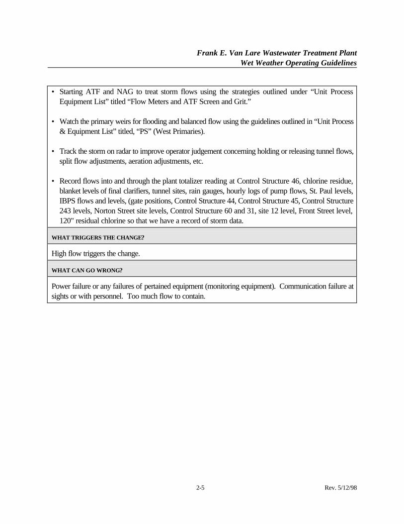
• Starting ATF and NAG to treat storm flows using the strategies outlined under “Unit ProcessEquipment List” titled “Flow Meters and ATF Screen and Grit.”
• Watch the primary weirs for flooding and balanced flow using the guidelines outlined in “Unit Process& Equipment List” titled, “PS” (West Primaries).
• Track the storm on radar to improve operator judgement concerning holding or releasing tunnel flows,split flow adjustments, aeration adjustments, etc.
• Record flows into and through the plant totalizer reading at Control Structure 46, chlorine residue,blanket levels of final clarifiers, tunnel sites, rain gauges, hourly logs of pump flows, St. Paul levels,IBPS flows and levels, (gate positions, Control Structure 44, Control Structure 45, Control Structure243 levels, Norton Street site levels, Control Structure 60 and 31, site 12 level, Front Street level,120" residual chlorine so that we have a record of storm data.
WHAT TRIGGERS THE CHANGE?
High flow triggers the change.
WHAT CAN GO WRONG?
Power failure or any failures of pertained equipment (monitoring equipment). Communication failure atsights or with personnel. Too much flow to contain.
Frank E. Van Lare Wastewater Treatment PlantWet Weather Operating Guidelines
3-1 Rev. 5/12/98
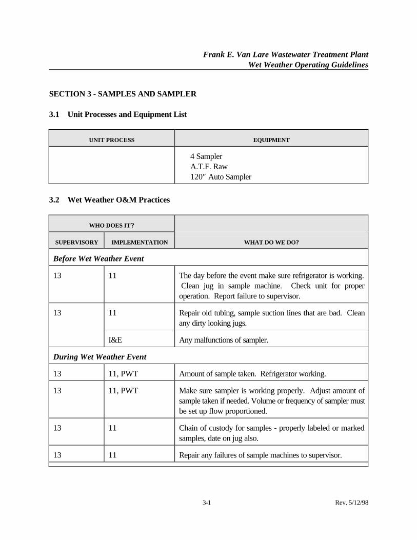
SECTION 3 - SAMPLES AND SAMPLER
3.1 Unit Processes and Equipment List
UNIT PROCESS EQUIPMENT
⋅ 4 Sampler⋅ A.T.F. Raw⋅ 120″ Auto Sampler
3.2 Wet Weather O&M Practices
WHO DOES IT?
SUPERVISORY IMPLEMENTATION WHAT DO WE DO?
Before Wet Weather Event
13 11 The day before the event make sure refrigerator is working. Clean jug in sample machine. Check unit for properoperation. Report failure to supervisor.
11 Repair old tubing, sample suction lines that are bad. Cleanany dirty looking jugs.
13
I&E Any malfunctions of sampler.
During Wet Weather Event
13 11, PWT Amount of sample taken. Refrigerator working.
13 11, PWT Make sure sampler is working properly. Adjust amount ofsample taken if needed. Volume or frequency of sampler mustbe set up flow proportioned.
13 11 Chain of custody for samples - properly labeled or markedsamples, date on jug also.
13 11 Repair any failures of sample machines to supervisor.
Frank E. Van Lare Wastewater Treatment PlantWet Weather Operating Guidelines
3-2 Rev. 5/12/98
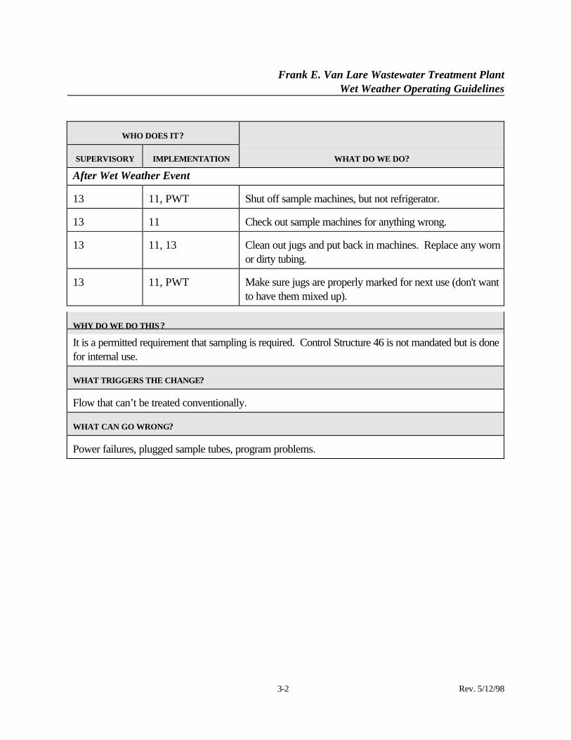
WHO DOES IT?
SUPERVISORY IMPLEMENTATION WHAT DO WE DO?
After Wet Weather Event
13 11, PWT Shut off sample machines, but not refrigerator.
13 11 Check out sample machines for anything wrong.
13 11, 13 Clean out jugs and put back in machines. Replace any wornor dirty tubing.
13 11, PWT Make sure jugs are properly marked for next use (don't wantto have them mixed up).
WHY DO WE DO THIS ?
It is a permitted requirement that sampling is required. Control Structure 46 is not mandated but is donefor internal use.
WHAT TRIGGERS THE CHANGE?
Flow that can’t be treated conventionally.
WHAT CAN GO WRONG?
Power failures, plugged sample tubes, program problems.
Frank E. Van Lare Wastewater Treatment PlantWet Weather Operating Guidelines
4-1 Rev. 5/12/98
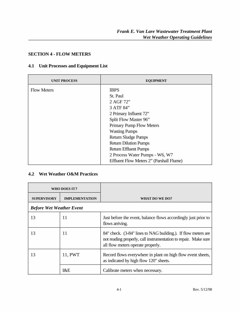
SECTION 4 - FLOW METERS
4.1 Unit Processes and Equipment List
UNIT PROCESS EQUIPMENT
Flow Meters ⋅ IBPS⋅ St. Paul⋅ 2 AGF 72”⋅ 3 ATF 84”⋅ 2 Primary Influent 72”⋅ Split Flow Master 96”⋅ Primary Pump Flow Meters⋅ Wasting Pumps⋅ Return Sludge Pumps⋅ Return Dilution Pumps⋅ Return Effluent Pumps⋅ 2 Process Water Pumps - W6, W7⋅ Effluent Flow Meters 2” (Parshall Flume)
4.2 Wet Weather O&M Practices
WHO DOES IT?
SUPERVISORY IMPLEMENTATION WHAT DO WE DO?
Before Wet Weather Event
13 11 Just before the event, balance flows accordingly just prior toflows arriving.
13 11 84" check. (3-84" lines to NAG building.). If flow meters arenot reading properly, call instrumentation to repair. Make sureall flow meters operate properly.
11, PWT Record flows everywhere in plant on high flow event sheets,as indicated by high flow 120" sheets.
13
I&E Calibrate meters when necessary.
Frank E. Van Lare Wastewater Treatment PlantWet Weather Operating Guidelines
4-2 Rev. 5/12/98
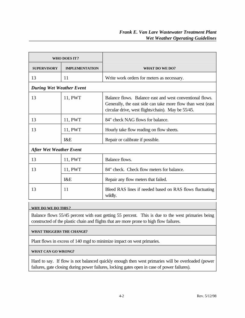
WHO DOES IT?
SUPERVISORY IMPLEMENTATION WHAT DO WE DO?
13 11 Write work orders for meters as necessary.
During Wet Weather Event
13 11, PWT Balance flows. Balance east and west conventional flows. Generally, the east side can take more flow than west (eastcircular drive, west flights/chain). May be 55/45.
13 11, PWT 84" check NAG flows for balance.
11, PWT Hourly take flow reading on flow sheets.13
I&E Repair or calibrate if possible.
After Wet Weather Event
13 11, PWT Balance flows.
11, PWT 84" check. Check flow meters for balance.13
I&E Repair any flow meters that failed.
13 11 Bleed RAS lines if needed based on RAS flows fluctuatingwildly.
WHY DO WE DO THIS ?
Balance flows 55/45 percent with east getting 55 percent. This is due to the west primaries beingconstructed of the plastic chain and flights that are more prone to high flow failures.
WHAT TRIGGERS THE CHANGE?
Plant flows in excess of 140 mgd to minimize impact on west primaries.
WHAT CAN GO WRONG?
Hard to say. If flow is not balanced quickly enough then west primaries will be overloaded (powerfailures, gate closing during power failures, locking gates open in case of power failures).
Frank E. Van Lare Wastewater Treatment PlantWet Weather Operating Guidelines
5-1 Rev. 5/12/98
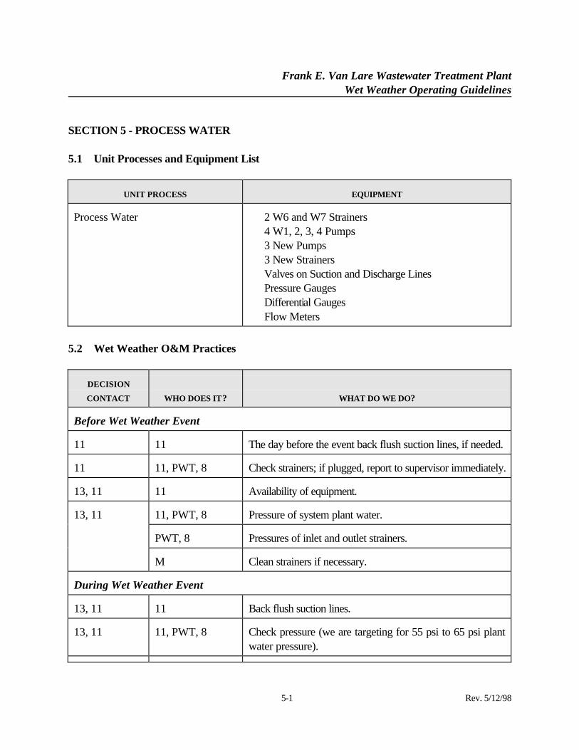
SECTION 5 - PROCESS WATER
5.1 Unit Processes and Equipment List
UNIT PROCESS EQUIPMENT
Process Water ⋅ 2 W6 and W7 Strainers⋅ 4 W1, 2, 3, 4 Pumps⋅ 3 New Pumps⋅ 3 New Strainers⋅ Valves on Suction and Discharge Lines⋅ Pressure Gauges⋅ Differential Gauges⋅ Flow Meters
5.2 Wet Weather O&M Practices
DECISION
CONTACT WHO DOES IT? WHAT DO WE DO?
Before Wet Weather Event
11 11 The day before the event back flush suction lines, if needed.
11 11, PWT, 8 Check strainers; if plugged, report to supervisor immediately.
13, 11 11 Availability of equipment.
11, PWT, 8 Pressure of system plant water.
PWT, 8 Pressures of inlet and outlet strainers.
13, 11
M Clean strainers if necessary.
During Wet Weather Event
13, 11 11 Back flush suction lines.
13, 11 11, PWT, 8 Check pressure (we are targeting for 55 psi to 65 psi plantwater pressure).
Frank E. Van Lare Wastewater Treatment PlantWet Weather Operating Guidelines
5-2 Rev. 5/12/98
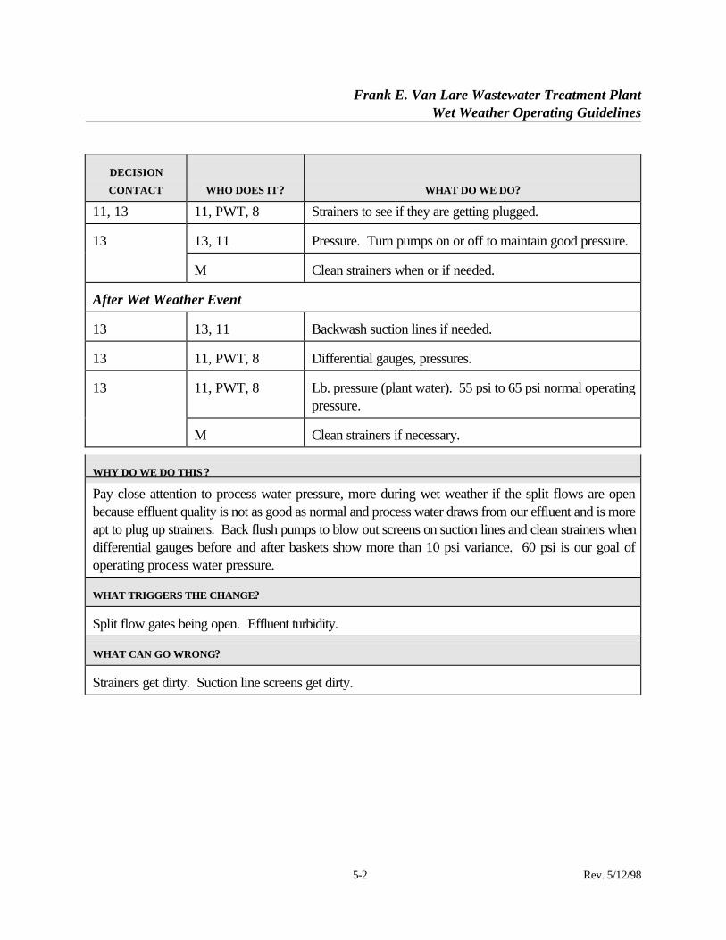
DECISION
CONTACT WHO DOES IT? WHAT DO WE DO?
11, 13 11, PWT, 8 Strainers to see if they are getting plugged.
13, 11 Pressure. Turn pumps on or off to maintain good pressure.13
M Clean strainers when or if needed.
After Wet Weather Event
13 13, 11 Backwash suction lines if needed.
13 11, PWT, 8 Differential gauges, pressures.
11, PWT, 8 Lb. pressure (plant water). 55 psi to 65 psi normal operatingpressure.
13
M Clean strainers if necessary.
WHY DO WE DO THIS ?
Pay close attention to process water pressure, more during wet weather if the split flows are openbecause effluent quality is not as good as normal and process water draws from our effluent and is moreapt to plug up strainers. Back flush pumps to blow out screens on suction lines and clean strainers whendifferential gauges before and after baskets show more than 10 psi variance. 60 psi is our goal ofoperating process water pressure.
WHAT TRIGGERS THE CHANGE?
Split flow gates being open. Effluent turbidity.
WHAT CAN GO WRONG?
Strainers get dirty. Suction line screens get dirty.
Frank E. Van Lare Wastewater Treatment PlantWet Weather Operating Guidelines
6-1 Rev. 5/12/98
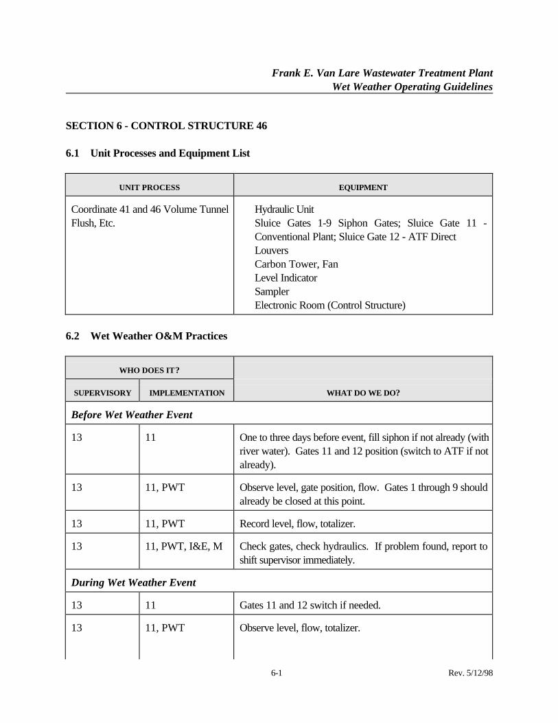
SECTION 6 - CONTROL STRUCTURE 46
6.1 Unit Processes and Equipment List
UNIT PROCESS EQUIPMENT
Coordinate 41 and 46 Volume TunnelFlush, Etc.
⋅ Hydraulic Unit⋅ Sluice Gates 1-9 Siphon Gates; Sluice Gate 11 -
Conventional Plant; Sluice Gate 12 - ATF Direct⋅ Louvers⋅ Carbon Tower, Fan⋅ Level Indicator⋅ Sampler⋅ Electronic Room (Control Structure)
6.2 Wet Weather O&M Practices
WHO DOES IT?
SUPERVISORY IMPLEMENTATION WHAT DO WE DO?
Before Wet Weather Event
13 11 One to three days before event, fill siphon if not already (withriver water). Gates 11 and 12 position (switch to ATF if notalready).
13 11, PWT Observe level, gate position, flow. Gates 1 through 9 shouldalready be closed at this point.
13 11, PWT Record level, flow, totalizer.
13 11, PWT, I&E, M Check gates, check hydraulics. If problem found, report toshift supervisor immediately.
During Wet Weather Event
13 11 Gates 11 and 12 switch if needed.
13 11, PWT Observe level, flow, totalizer.
Frank E. Van Lare Wastewater Treatment PlantWet Weather Operating Guidelines
6-2 Rev. 5/12/98
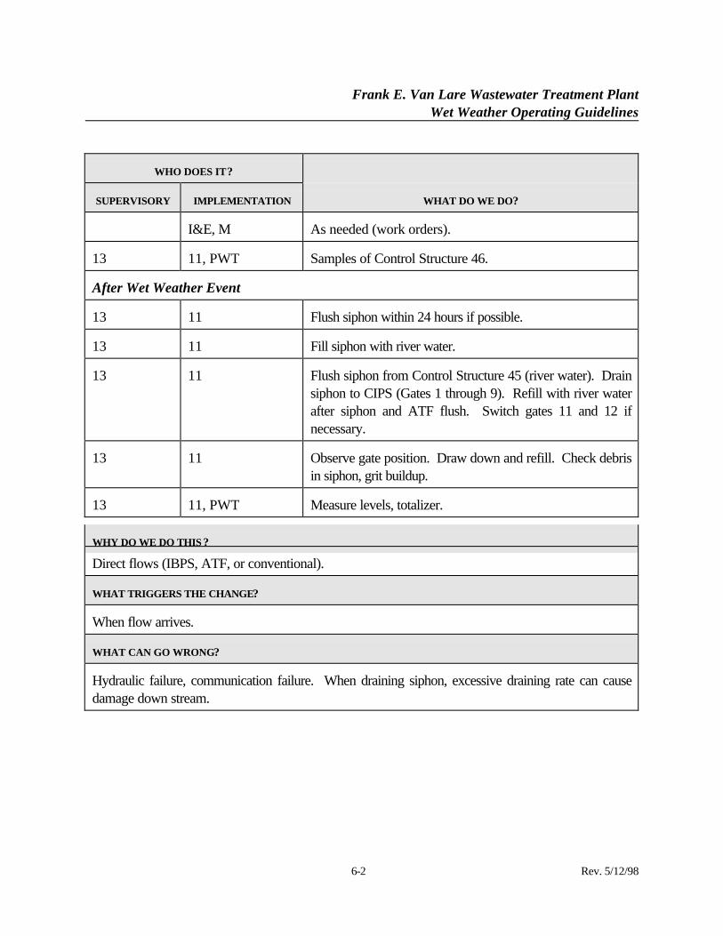
WHO DOES IT?
SUPERVISORY IMPLEMENTATION WHAT DO WE DO?
I&E, M As needed (work orders).
13 11, PWT Samples of Control Structure 46.
After Wet Weather Event
13 11 Flush siphon within 24 hours if possible.
13 11 Fill siphon with river water.
13 11 Flush siphon from Control Structure 45 (river water). Drainsiphon to CIPS (Gates 1 through 9). Refill with river waterafter siphon and ATF flush. Switch gates 11 and 12 ifnecessary.
13 11 Observe gate position. Draw down and refill. Check debrisin siphon, grit buildup.
13 11, PWT Measure levels, totalizer.
WHY DO WE DO THIS ?
Direct flows (IBPS, ATF, or conventional).
WHAT TRIGGERS THE CHANGE?
When flow arrives.
WHAT CAN GO WRONG?
Hydraulic failure, communication failure. When draining siphon, excessive draining rate can causedamage down stream.
Frank E. Van Lare Wastewater Treatment PlantWet Weather Operating Guidelines
7-1 Rev. 5/12/98
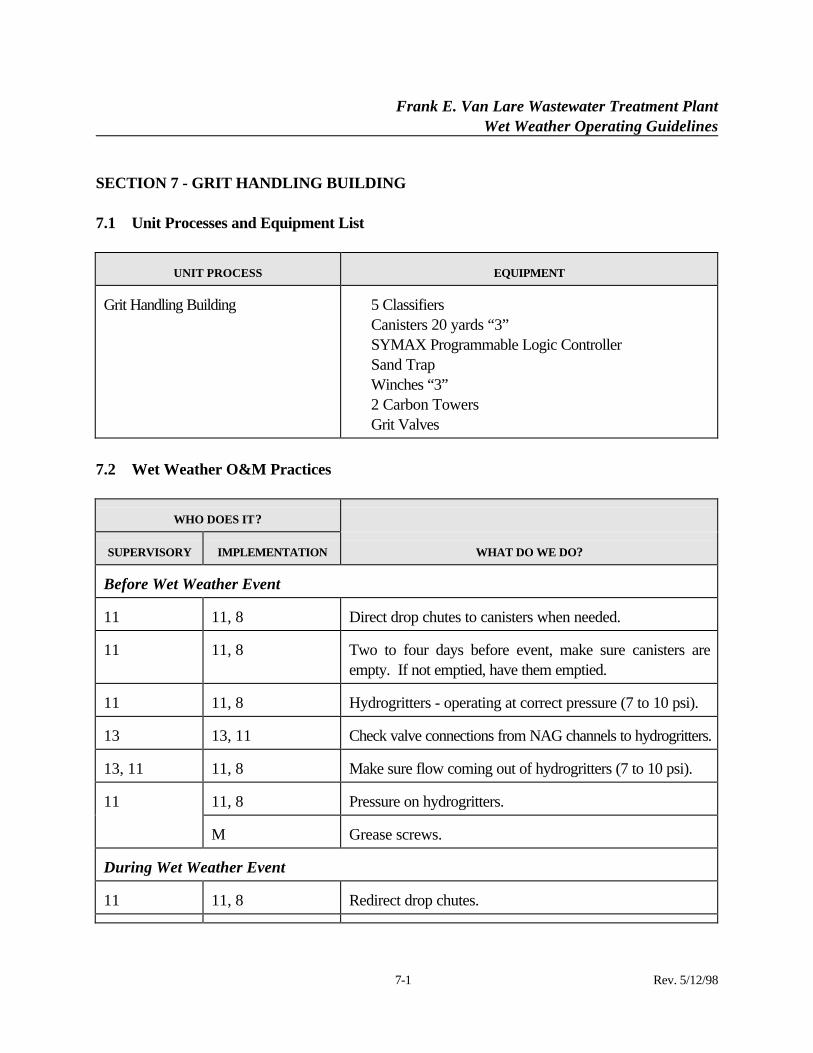
SECTION 7 - GRIT HANDLING BUILDING
7.1 Unit Processes and Equipment List
UNIT PROCESS EQUIPMENT
Grit Handling Building ⋅ 5 Classifiers⋅ Canisters 20 yards “3”⋅ SYMAX Programmable Logic Controller⋅ Sand Trap⋅ Winches “3”⋅ 2 Carbon Towers⋅ Grit Valves
7.2 Wet Weather O&M Practices
WHO DOES IT?
SUPERVISORY IMPLEMENTATION WHAT DO WE DO?
Before Wet Weather Event
11 11, 8 Direct drop chutes to canisters when needed.
11 11, 8 Two to four days before event, make sure canisters areempty. If not emptied, have them emptied.
11 11, 8 Hydrogritters - operating at correct pressure (7 to 10 psi).
13 13, 11 Check valve connections from NAG channels to hydrogritters.
13, 11 11, 8 Make sure flow coming out of hydrogritters (7 to 10 psi).
11, 8 Pressure on hydrogritters.11
M Grease screws.
During Wet Weather Event
11 11, 8 Redirect drop chutes.
Frank E. Van Lare Wastewater Treatment PlantWet Weather Operating Guidelines
7-2 Rev. 5/12/98
WHO DOES IT?
SUPERVISORY IMPLEMENTATION WHAT DO WE DO?
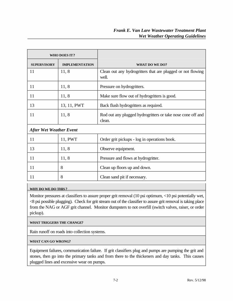
11 11, 8 Clean out any hydrogritters that are plugged or not flowingwell.
11 11, 8 Pressure on hydrogritters.
11 11, 8 Make sure flow out of hydrogritters is good.
13 13, 11, PWT Back flush hydrogritters as required.
11 11, 8 Rod out any plugged hydrogritters or take nose cone off andclean.
After Wet Weather Event
11 11, PWT Order grit pickups - log in operations book.
13 11, 8 Observe equipment.
11 11, 8 Pressure and flows at hydrogritter.
11 8 Clean up floors up and down.
11 8 Clean sand pit if necessary.
WHY DO WE DO THIS ?
Monitor pressures at classifiers to assure proper grit removal (10 psi optimum, <10 psi potentially wet,<8 psi possible plugging). Check for grit stream out of the classifier to assure grit removal is taking placefrom the NAG or AGF grit channel. Monitor dumpsters to not overfill (switch valves, raiser, or orderpickup).
WHAT TRIGGERS THE CHANGE?
Rain runoff on roads into collection systems.
WHAT CAN GO WRONG?
Equipment failures, communication failure. If grit classifiers plug and pumps are pumping the grit andstones, then go into the primary tanks and from there to the thickeners and day tanks. This causesplugged lines and excessive wear on pumps.
Frank E. Van Lare Wastewater Treatment PlantWet Weather Operating Guidelines
7-3 Rev. 5/12/98
Frank E. Van Lare Wastewater Treatment PlantWet Weather Operating Guidelines
8-1 Rev. 5/12/98
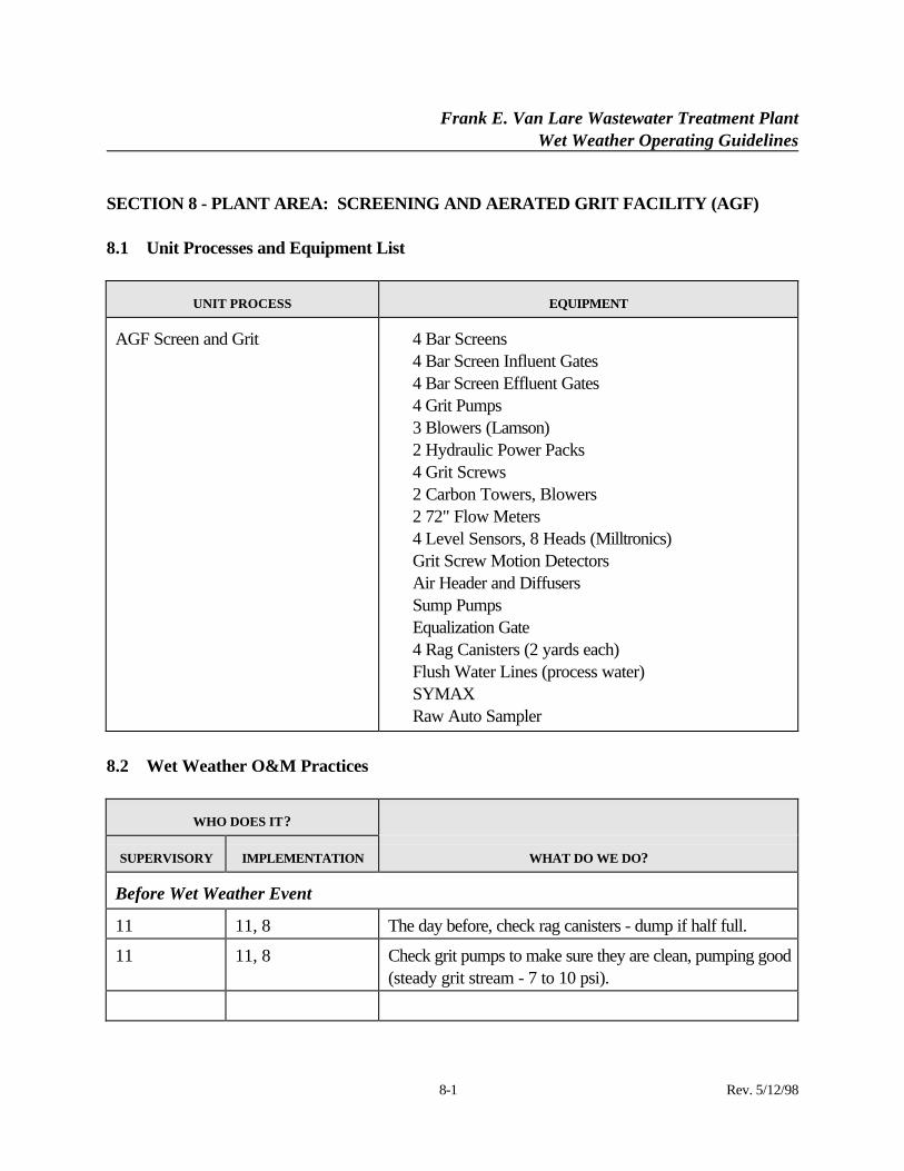
SECTION 8 - PLANT AREA: SCREENING AND AERATED GRIT FACILITY (AGF)
8.1 Unit Processes and Equipment List
UNIT PROCESS EQUIPMENT
AGF Screen and Grit ⋅ 4 Bar Screens⋅ 4 Bar Screen Influent Gates⋅ 4 Bar Screen Effluent Gates⋅ 4 Grit Pumps⋅ 3 Blowers (Lamson)⋅ 2 Hydraulic Power Packs⋅ 4 Grit Screws⋅ 2 Carbon Towers, Blowers⋅ 2 72" Flow Meters⋅ 4 Level Sensors, 8 Heads (Milltronics)⋅ Grit Screw Motion Detectors⋅ Air Header and Diffusers⋅ Sump Pumps⋅ Equalization Gate⋅ 4 Rag Canisters (2 yards each)⋅ Flush Water Lines (process water)⋅ SYMAX⋅ Raw Auto Sampler
8.2 Wet Weather O&M Practices
WHO DOES IT?
SUPERVISORY IMPLEMENTATION WHAT DO WE DO?
Before Wet Weather Event
11 11, 8 The day before, check rag canisters - dump if half full.
11 11, 8 Check grit pumps to make sure they are clean, pumping good(steady grit stream - 7 to 10 psi).
Frank E. Van Lare Wastewater Treatment PlantWet Weather Operating Guidelines
8-2 Rev. 5/12/98
WHO DOES IT?
SUPERVISORY IMPLEMENTATION WHAT DO WE DO?
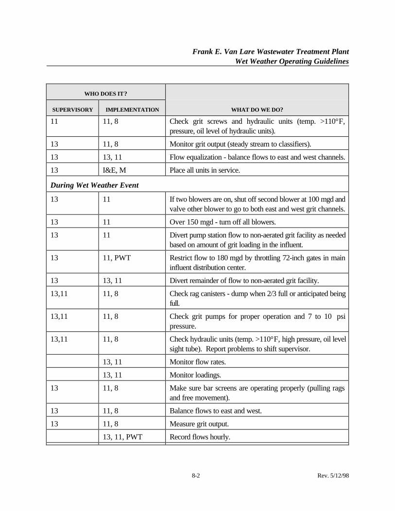
11 11, 8 Check grit screws and hydraulic units (temp. >110°F,pressure, oil level of hydraulic units).
13 11, 8 Monitor grit output (steady stream to classifiers).
13 13, 11 Flow equalization - balance flows to east and west channels.
13 I&E, M Place all units in service.
During Wet Weather Event
13 11 If two blowers are on, shut off second blower at 100 mgd andvalve other blower to go to both east and west grit channels.
13 11 Over 150 mgd - turn off all blowers.
13 11 Divert pump station flow to non-aerated grit facility as neededbased on amount of grit loading in the influent.
13 11, PWT Restrict flow to 180 mgd by throttling 72-inch gates in maininfluent distribution center.
13 13, 11 Divert remainder of flow to non-aerated grit facility.
13,11 11, 8 Check rag canisters - dump when 2/3 full or anticipated beingfull.
13,11 11, 8 Check grit pumps for proper operation and 7 to 10 psipressure.
13,11 11, 8 Check hydraulic units (temp. >110°F, high pressure, oil levelsight tube). Report problems to shift supervisor.
13, 11 Monitor flow rates.
13, 11 Monitor loadings.
13 11, 8 Make sure bar screens are operating properly (pulling ragsand free movement).
13 11, 8 Balance flows to east and west.
13 11, 8 Measure grit output.
13, 11, PWT Record flows hourly.
Frank E. Van Lare Wastewater Treatment PlantWet Weather Operating Guidelines
8-3 Rev. 5/12/98
WHO DOES IT?
SUPERVISORY IMPLEMENTATION WHAT DO WE DO?
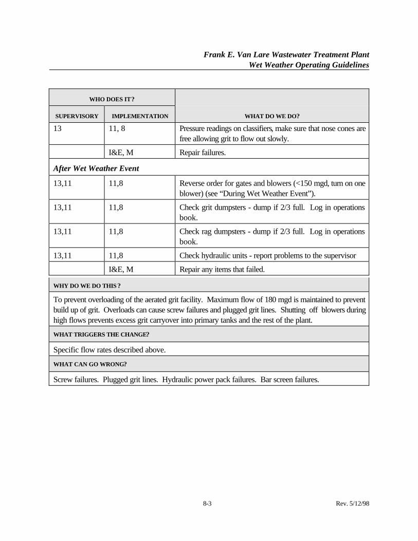
13 11, 8 Pressure readings on classifiers, make sure that nose cones arefree allowing grit to flow out slowly.
I&E, M Repair failures.
After Wet Weather Event
13,11 11,8 Reverse order for gates and blowers (<150 mgd, turn on oneblower) (see “During Wet Weather Event”).
13,11 11,8 Check grit dumpsters - dump if 2/3 full. Log in operationsbook.
13,11 11,8 Check rag dumpsters - dump if 2/3 full. Log in operationsbook.
13,11 11,8 Check hydraulic units - report problems to the supervisor
I&E, M Repair any items that failed.
WHY DO WE DO THIS ?
To prevent overloading of the aerated grit facility. Maximum flow of 180 mgd is maintained to preventbuild up of grit. Overloads can cause screw failures and plugged grit lines. Shutting off blowers duringhigh flows prevents excess grit carryover into primary tanks and the rest of the plant.
WHAT TRIGGERS THE CHANGE?
Specific flow rates described above.
WHAT CAN GO WRONG?
Screw failures. Plugged grit lines. Hydraulic power pack failures. Bar screen failures.
Frank E. Van Lare Wastewater Treatment PlantWet Weather Operating Guidelines
9-1 Rev. 5/12/98
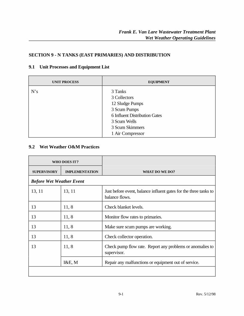
SECTION 9 - N TANKS (EAST PRIMARIES) AND DISTRIBUTION
9.1 Unit Processes and Equipment List
UNIT PROCESS EQUIPMENT
N’s ⋅ 3 Tanks⋅ 3 Collectors⋅ 12 Sludge Pumps⋅ 3 Scum Pumps⋅ 6 Influent Distribution Gates⋅ 3 Scum Wells⋅ 3 Scum Skimmers⋅ 1 Air Compressor
9.2 Wet Weather O&M Practices
WHO DOES IT?
SUPERVISORY IMPLEMENTATION WHAT DO WE DO?
Before Wet Weather Event
13, 11 13, 11 Just before event, balance influent gates for the three tanks tobalance flows.
13 11, 8 Check blanket levels.
13 11, 8 Monitor flow rates to primaries.
13 11, 8 Make sure scum pumps are working.
13 11, 8 Check collector operation.
11, 8 Check pump flow rate. Report any problems or anomalies tosupervisor.
13
I&E, M Repair any malfunctions or equipment out of service.
Frank E. Van Lare Wastewater Treatment PlantWet Weather Operating Guidelines
9-2 Rev. 5/12/98
WHO DOES IT?
SUPERVISORY IMPLEMENTATION WHAT DO WE DO?
During Wet Weather Event
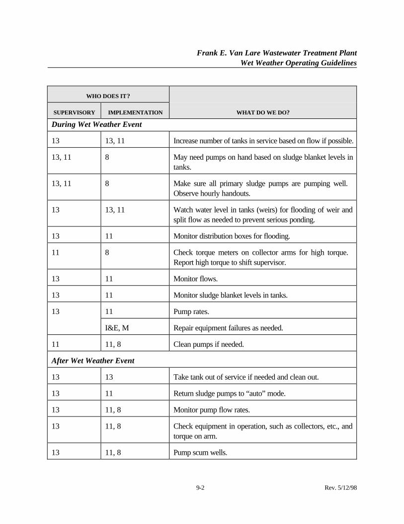
13 13, 11 Increase number of tanks in service based on flow if possible.
13, 11 8 May need pumps on hand based on sludge blanket levels intanks.
13, 11 8 Make sure all primary sludge pumps are pumping well. Observe hourly handouts.
13 13, 11 Watch water level in tanks (weirs) for flooding of weir andsplit flow as needed to prevent serious ponding.
13 11 Monitor distribution boxes for flooding.
11 8 Check torque meters on collector arms for high torque. Report high torque to shift supervisor.
13 11 Monitor flows.
13 11 Monitor sludge blanket levels in tanks.
11 Pump rates.13
I&E, M Repair equipment failures as needed.
11 11, 8 Clean pumps if needed.
After Wet Weather Event
13 13 Take tank out of service if needed and clean out.
13 11 Return sludge pumps to “auto” mode.
13 11, 8 Monitor pump flow rates.
13 11, 8 Check equipment in operation, such as collectors, etc., andtorque on arm.
13 11, 8 Pump scum wells.
Frank E. Van Lare Wastewater Treatment PlantWet Weather Operating Guidelines
9-3 Rev. 5/12/98
WHO DOES IT?
SUPERVISORY IMPLEMENTATION WHAT DO WE DO?
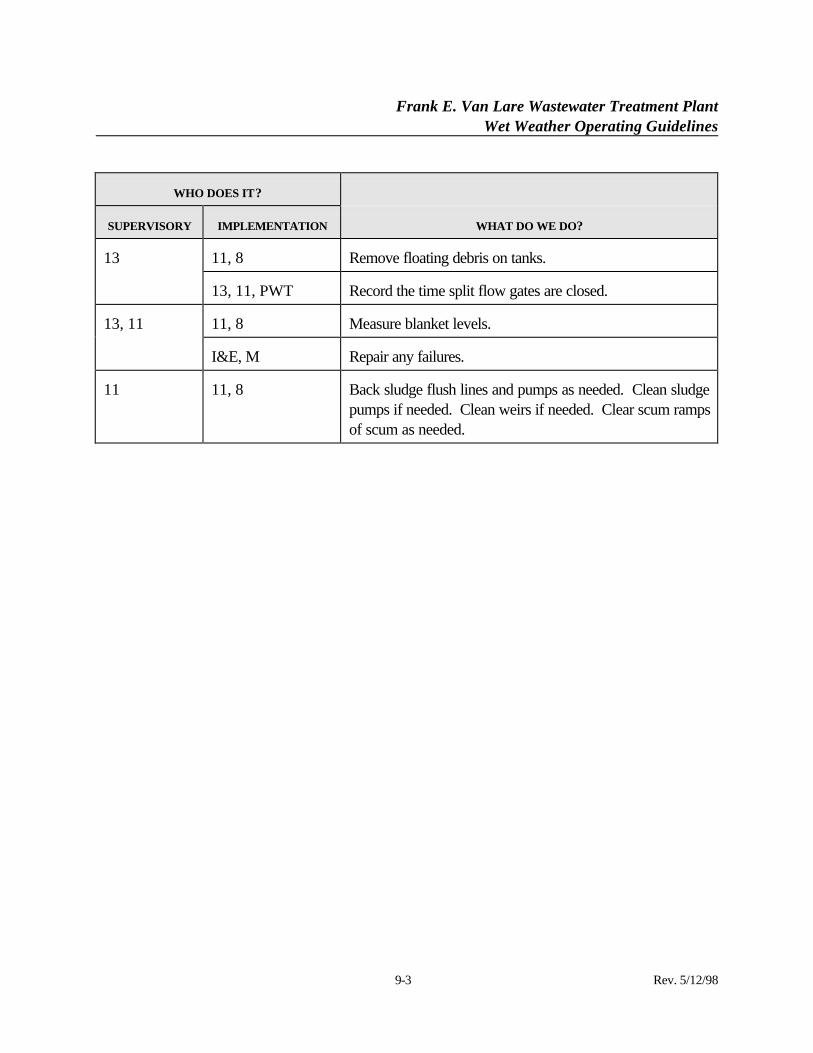
11, 8 Remove floating debris on tanks.13
13, 11, PWT Record the time split flow gates are closed.
11, 8 Measure blanket levels.13, 11
I&E, M Repair any failures.
11 11, 8 Back sludge flush lines and pumps as needed. Clean sludgepumps if needed. Clean weirs if needed. Clear scum rampsof scum as needed.
Frank E. Van Lare Wastewater Treatment PlantWet Weather Operating Guidelines
10-1 Rev. 5/12/98
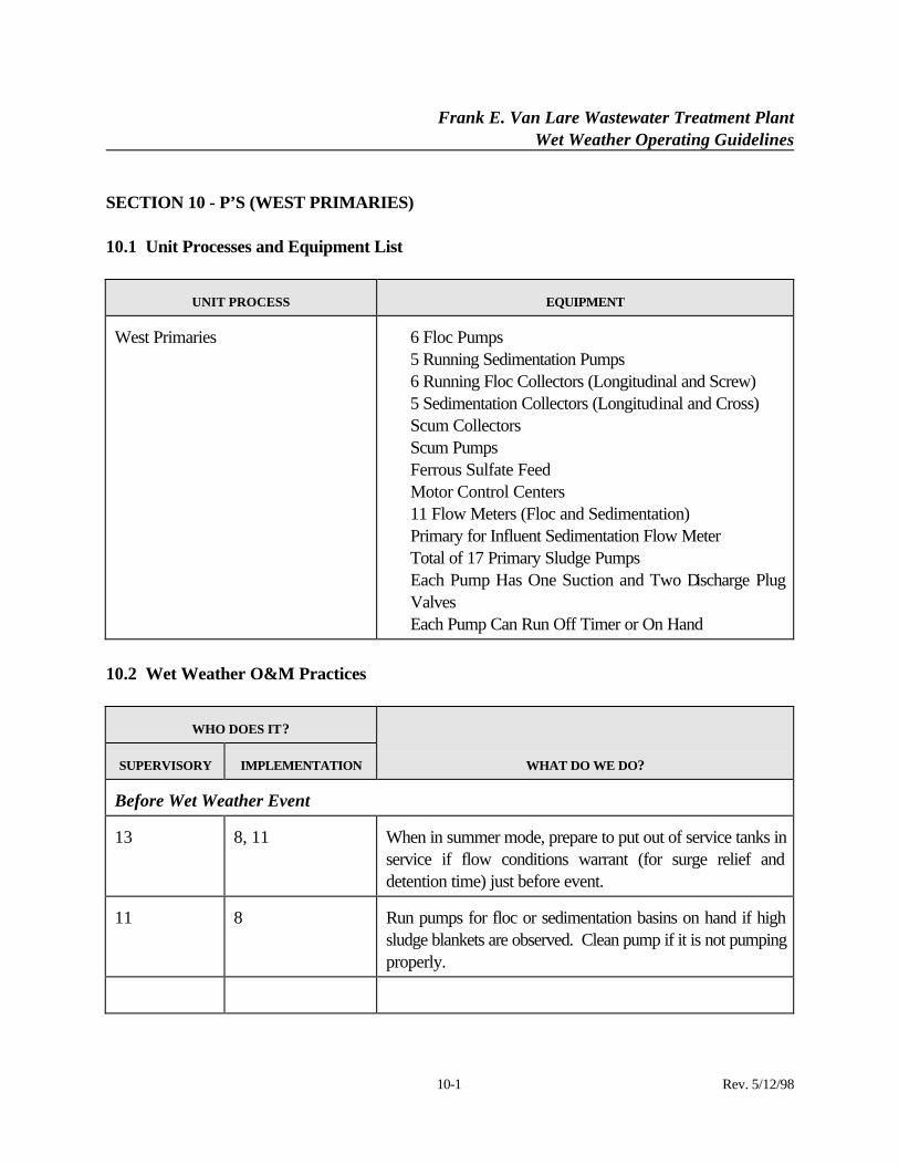
SECTION 10 - P’S (WEST PRIMARIES)
10.1 Unit Processes and Equipment List
UNIT PROCESS EQUIPMENT
West Primaries ⋅ 6 Floc Pumps⋅ 5 Running Sedimentation Pumps⋅ 6 Running Floc Collectors (Longitudinal and Screw)⋅ 5 Sedimentation Collectors (Longitudinal and Cross)⋅ Scum Collectors⋅ Scum Pumps⋅ Ferrous Sulfate Feed⋅ Motor Control Centers⋅ 11 Flow Meters (Floc and Sedimentation)⋅ Primary for Influent Sedimentation Flow Meter⋅ Total of 17 Primary Sludge Pumps⋅ Each Pump Has One Suction and Two Discharge Plug
Valves⋅ Each Pump Can Run Off Timer or On Hand
10.2 Wet Weather O&M Practices
WHO DOES IT?
SUPERVISORY IMPLEMENTATION WHAT DO WE DO?
Before Wet Weather Event
13 8, 11 When in summer mode, prepare to put out of service tanks inservice if flow conditions warrant (for surge relief anddetention time) just before event.
11 8 Run pumps for floc or sedimentation basins on hand if highsludge blankets are observed. Clean pump if it is not pumpingproperly.
Frank E. Van Lare Wastewater Treatment PlantWet Weather Operating Guidelines
10-2 Rev. 5/12/98
WHO DOES IT?
SUPERVISORY IMPLEMENTATION WHAT DO WE DO?
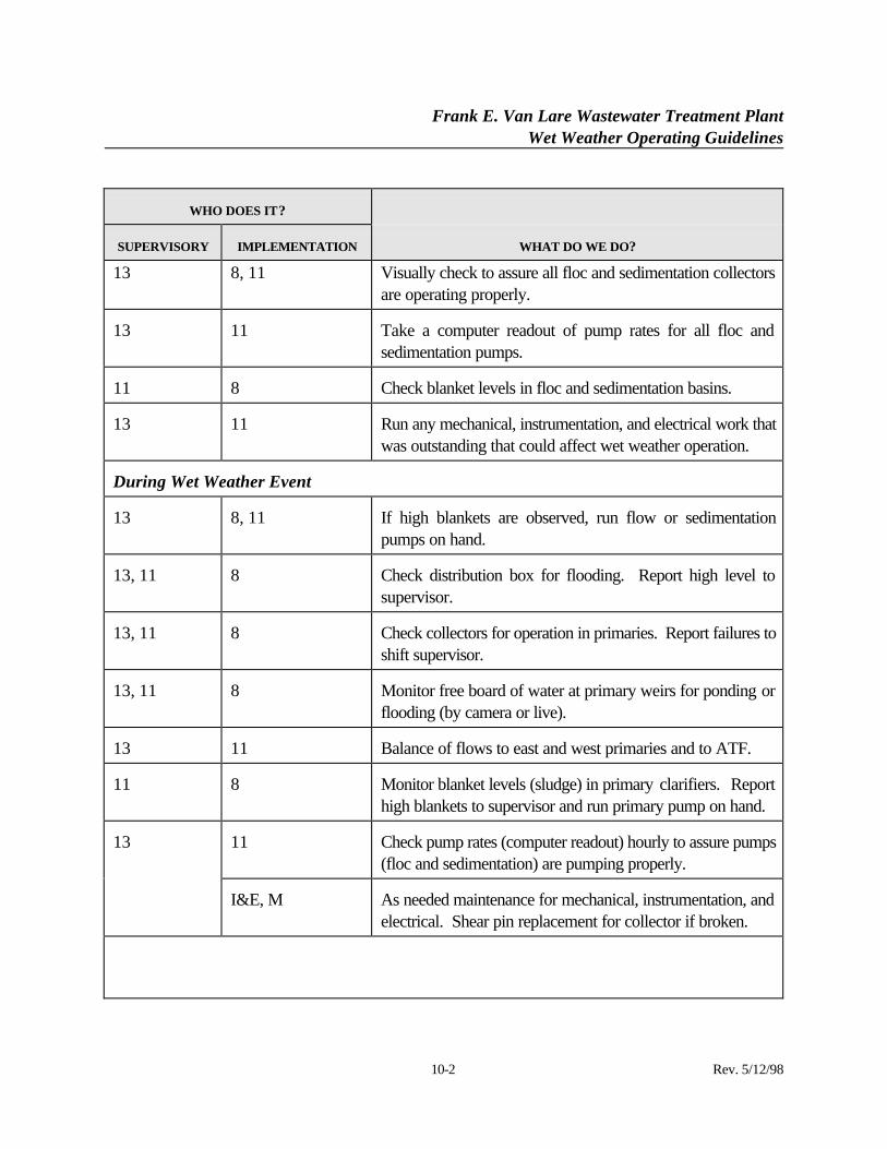
13 8, 11 Visually check to assure all floc and sedimentation collectorsare operating properly.
13 11 Take a computer readout of pump rates for all floc andsedimentation pumps.
11 8 Check blanket levels in floc and sedimentation basins.
13 11 Run any mechanical, instrumentation, and electrical work thatwas outstanding that could affect wet weather operation.
During Wet Weather Event
13 8, 11 If high blankets are observed, run flow or sedimentationpumps on hand.
13, 11 8 Check distribution box for flooding. Report high level tosupervisor.
13, 11 8 Check collectors for operation in primaries. Report failures toshift supervisor.
13, 11 8 Monitor free board of water at primary weirs for ponding orflooding (by camera or live).
13 11 Balance of flows to east and west primaries and to ATF.
11 8 Monitor blanket levels (sludge) in primary clarifiers. Reporthigh blankets to supervisor and run primary pump on hand.
11 Check pump rates (computer readout) hourly to assure pumps(floc and sedimentation) are pumping properly.
13
I&E, M As needed maintenance for mechanical, instrumentation, andelectrical. Shear pin replacement for collector if broken.
Frank E. Van Lare Wastewater Treatment PlantWet Weather Operating Guidelines
10-3 Rev. 5/12/98
WHO DOES IT?
SUPERVISORY IMPLEMENTATION WHAT DO WE DO?
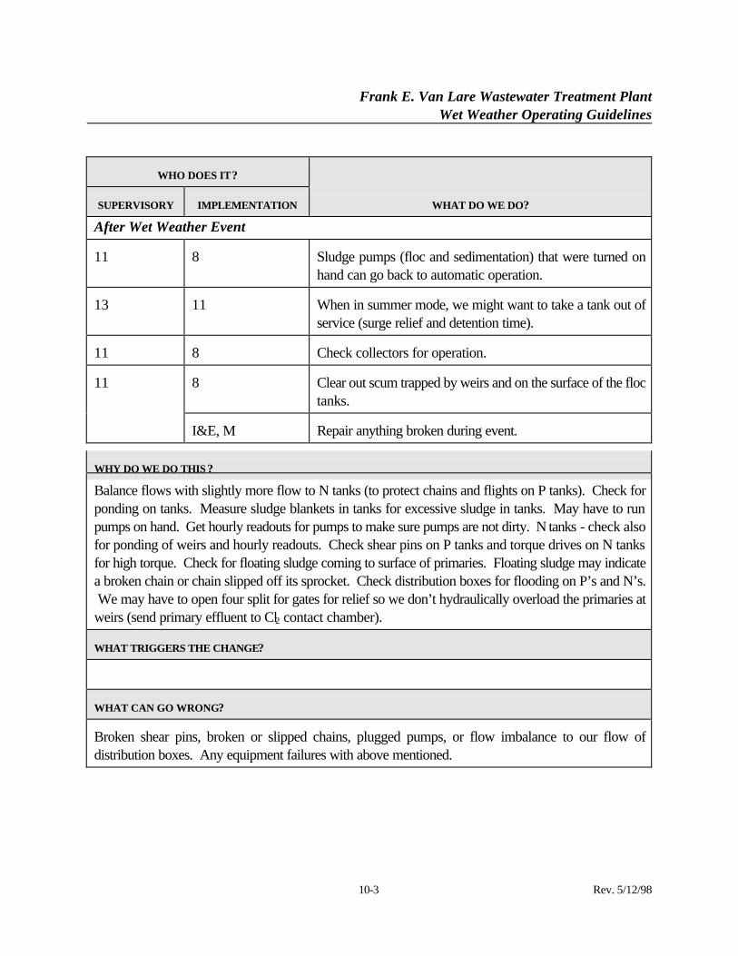
After Wet Weather Event
11 8 Sludge pumps (floc and sedimentation) that were turned onhand can go back to automatic operation.
13 11 When in summer mode, we might want to take a tank out ofservice (surge relief and detention time).
11 8 Check collectors for operation.
8 Clear out scum trapped by weirs and on the surface of the floctanks.
11
I&E, M Repair anything broken during event.
WHY DO WE DO THIS ?
Balance flows with slightly more flow to N tanks (to protect chains and flights on P tanks). Check forponding on tanks. Measure sludge blankets in tanks for excessive sludge in tanks. May have to runpumps on hand. Get hourly readouts for pumps to make sure pumps are not dirty. N tanks - check alsofor ponding of weirs and hourly readouts. Check shear pins on P tanks and torque drives on N tanksfor high torque. Check for floating sludge coming to surface of primaries. Floating sludge may indicatea broken chain or chain slipped off its sprocket. Check distribution boxes for flooding on P’s and N’s. We may have to open four split for gates for relief so we don’t hydraulically overload the primaries atweirs (send primary effluent to Cl2 contact chamber).
WHAT TRIGGERS THE CHANGE?
WHAT CAN GO WRONG?
Broken shear pins, broken or slipped chains, plugged pumps, or flow imbalance to our flow ofdistribution boxes. Any equipment failures with above mentioned.
Frank E. Van Lare Wastewater Treatment PlantWet Weather Operating Guidelines
11-1 Rev. 5/12/98
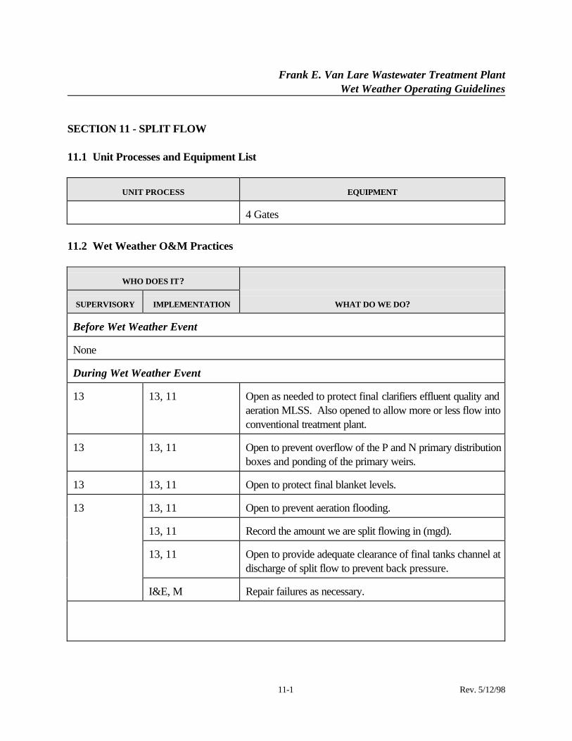
SECTION 11 - SPLIT FLOW
11.1 Unit Processes and Equipment List
UNIT PROCESS EQUIPMENT
4 Gates
11.2 Wet Weather O&M Practices
WHO DOES IT?
SUPERVISORY IMPLEMENTATION WHAT DO WE DO?
Before Wet Weather Event
None
During Wet Weather Event
13 13, 11 Open as needed to protect final clarifiers effluent quality andaeration MLSS. Also opened to allow more or less flow intoconventional treatment plant.
13 13, 11 Open to prevent overflow of the P and N primary distributionboxes and ponding of the primary weirs.
13 13, 11 Open to protect final blanket levels.
13, 11 Open to prevent aeration flooding.
13, 11 Record the amount we are split flowing in (mgd).
13, 11 Open to provide adequate clearance of final tanks channel atdischarge of split flow to prevent back pressure.
13
I&E, M Repair failures as necessary.
Frank E. Van Lare Wastewater Treatment PlantWet Weather Operating Guidelines
11-2 Rev. 5/12/98
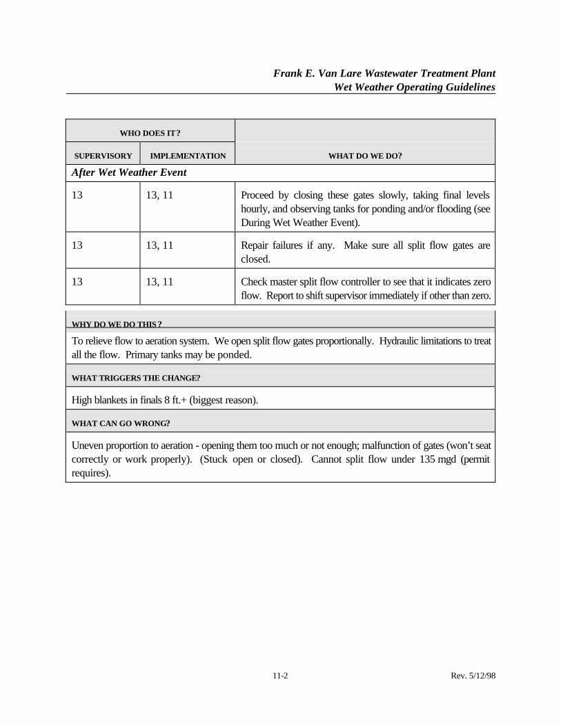
WHO DOES IT?
SUPERVISORY IMPLEMENTATION WHAT DO WE DO?
After Wet Weather Event
13 13, 11 Proceed by closing these gates slowly, taking final levelshourly, and observing tanks for ponding and/or flooding (seeDuring Wet Weather Event).
13 13, 11 Repair failures if any. Make sure all split flow gates areclosed.
13 13, 11 Check master split flow controller to see that it indicates zeroflow. Report to shift supervisor immediately if other than zero.
WHY DO WE DO THIS ?
To relieve flow to aeration system. We open split flow gates proportionally. Hydraulic limitations to treatall the flow. Primary tanks may be ponded.
WHAT TRIGGERS THE CHANGE?
High blankets in finals 8 ft.+ (biggest reason).
WHAT CAN GO WRONG?
Uneven proportion to aeration - opening them too much or not enough; malfunction of gates (won’t seatcorrectly or work properly). (Stuck open or closed). Cannot split flow under 135 mgd (permitrequires).
Frank E. Van Lare Wastewater Treatment PlantWet Weather Operating Guidelines
12-1 Rev. 5/12/98
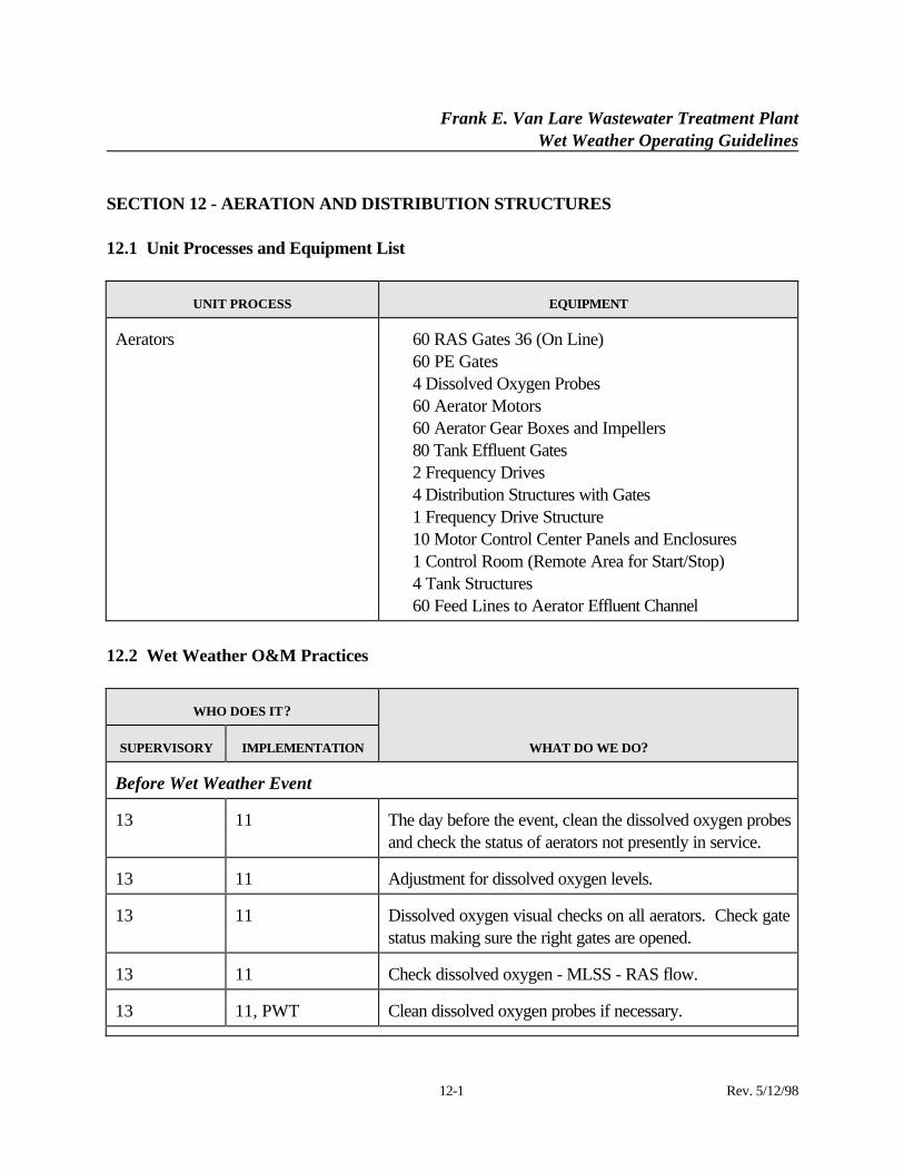
SECTION 12 - AERATION AND DISTRIBUTION STRUCTURES
12.1 Unit Processes and Equipment List
UNIT PROCESS EQUIPMENT
Aerators ⋅ 60 RAS Gates 36 (On Line)⋅ 60 PE Gates⋅ 4 Dissolved Oxygen Probes⋅ 60 Aerator Motors⋅ 60 Aerator Gear Boxes and Impellers⋅ 80 Tank Effluent Gates⋅ 2 Frequency Drives⋅ 4 Distribution Structures with Gates⋅ 1 Frequency Drive Structure⋅ 10 Motor Control Center Panels and Enclosures⋅ 1 Control Room (Remote Area for Start/Stop)⋅ 4 Tank Structures⋅ 60 Feed Lines to Aerator Effluent Channel
12.2 Wet Weather O&M Practices
WHO DOES IT?
SUPERVISORY IMPLEMENTATION WHAT DO WE DO?
Before Wet Weather Event
13 11 The day before the event, clean the dissolved oxygen probesand check the status of aerators not presently in service.
13 11 Adjustment for dissolved oxygen levels.
13 11 Dissolved oxygen visual checks on all aerators. Check gatestatus making sure the right gates are opened.
13 11 Check dissolved oxygen - MLSS - RAS flow.
13 11, PWT Clean dissolved oxygen probes if necessary.
Frank E. Van Lare Wastewater Treatment PlantWet Weather Operating Guidelines
12-2 Rev. 5/12/98
WHO DOES IT?
SUPERVISORY IMPLEMENTATION WHAT DO WE DO?
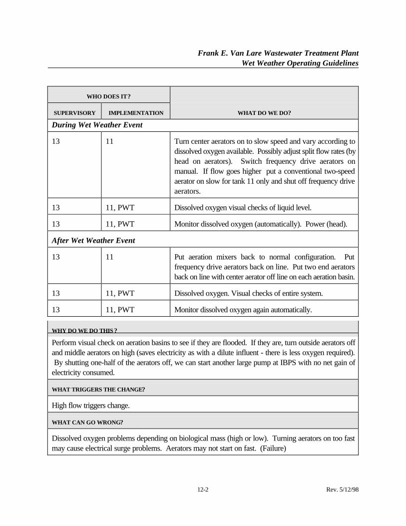
During Wet Weather Event
13 11 Turn center aerators on to slow speed and vary according todissolved oxygen available. Possibly adjust split flow rates (byhead on aerators). Switch frequency drive aerators onmanual. If flow goes higher put a conventional two-speedaerator on slow for tank 11 only and shut off frequency driveaerators.
13 11, PWT Dissolved oxygen visual checks of liquid level.
13 11, PWT Monitor dissolved oxygen (automatically). Power (head).
After Wet Weather Event
13 11 Put aeration mixers back to normal configuration. Putfrequency drive aerators back on line. Put two end aeratorsback on line with center aerator off line on each aeration basin.
13 11, PWT Dissolved oxygen. Visual checks of entire system.
13 11, PWT Monitor dissolved oxygen again automatically.
WHY DO WE DO THIS ?
Perform visual check on aeration basins to see if they are flooded. If they are, turn outside aerators offand middle aerators on high (saves electricity as with a dilute influent - there is less oxygen required). By shutting one-half of the aerators off, we can start another large pump at IBPS with no net gain ofelectricity consumed.
WHAT TRIGGERS THE CHANGE?
High flow triggers change.
WHAT CAN GO WRONG?
Dissolved oxygen problems depending on biological mass (high or low). Turning aerators on too fastmay cause electrical surge problems. Aerators may not start on fast. (Failure)
Frank E. Van Lare Wastewater Treatment PlantWet Weather Operating Guidelines
SECTION 12 (Continued):
12-3 Rev. 5/12/98
Frank E. Van Lare Wastewater Treatment PlantWet Weather Operating Guidelines
13-1 Rev. 5/12/98
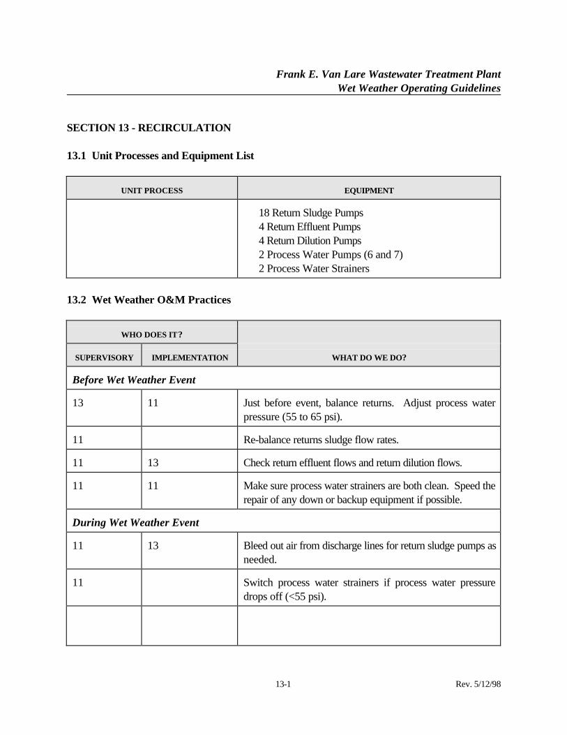
SECTION 13 - RECIRCULATION
13.1 Unit Processes and Equipment List
UNIT PROCESS EQUIPMENT
⋅ 18 Return Sludge Pumps⋅ 4 Return Effluent Pumps⋅ 4 Return Dilution Pumps⋅ 2 Process Water Pumps (6 and 7)⋅ 2 Process Water Strainers
13.2 Wet Weather O&M Practices
WHO DOES IT?
SUPERVISORY IMPLEMENTATION WHAT DO WE DO?
Before Wet Weather Event
13 11 Just before event, balance returns. Adjust process waterpressure (55 to 65 psi).
11 Re-balance returns sludge flow rates.
11 13 Check return effluent flows and return dilution flows.
11 11 Make sure process water strainers are both clean. Speed therepair of any down or backup equipment if possible.
During Wet Weather Event
11 13 Bleed out air from discharge lines for return sludge pumps asneeded.
11 Switch process water strainers if process water pressuredrops off (<55 psi).
Frank E. Van Lare Wastewater Treatment PlantWet Weather Operating Guidelines
13-2 Rev. 5/12/98
WHO DOES IT?
SUPERVISORY IMPLEMENTATION WHAT DO WE DO?
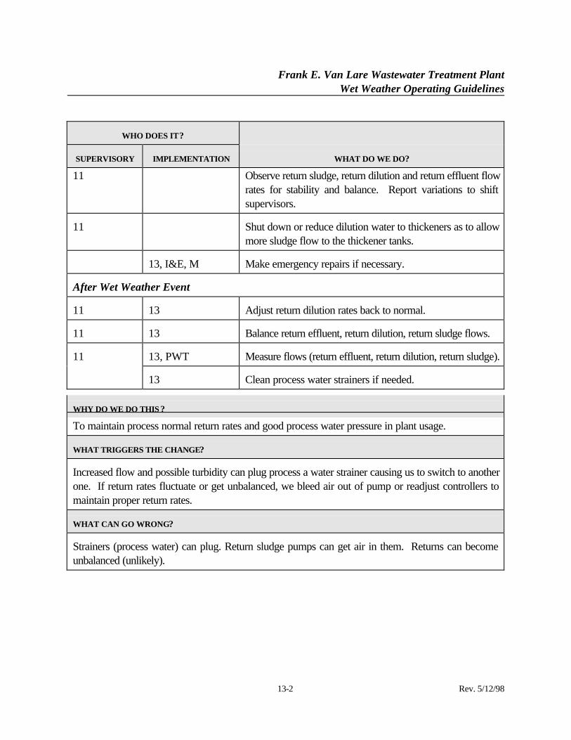
11 Observe return sludge, return dilution and return effluent flowrates for stability and balance. Report variations to shiftsupervisors.
11 Shut down or reduce dilution water to thickeners as to allowmore sludge flow to the thickener tanks.
13, I&E, M Make emergency repairs if necessary.
After Wet Weather Event
11 13 Adjust return dilution rates back to normal.
11 13 Balance return effluent, return dilution, return sludge flows.
13, PWT Measure flows (return effluent, return dilution, return sludge).11
13 Clean process water strainers if needed.
WHY DO WE DO THIS ?
To maintain process normal return rates and good process water pressure in plant usage.
WHAT TRIGGERS THE CHANGE?
Increased flow and possible turbidity can plug process a water strainer causing us to switch to anotherone. If return rates fluctuate or get unbalanced, we bleed air out of pump or readjust controllers tomaintain proper return rates.
WHAT CAN GO WRONG?
Strainers (process water) can plug. Return sludge pumps can get air in them. Returns can becomeunbalanced (unlikely).
Frank E. Van Lare Wastewater Treatment PlantWet Weather Operating Guidelines
14-1 Rev. 5/12/98
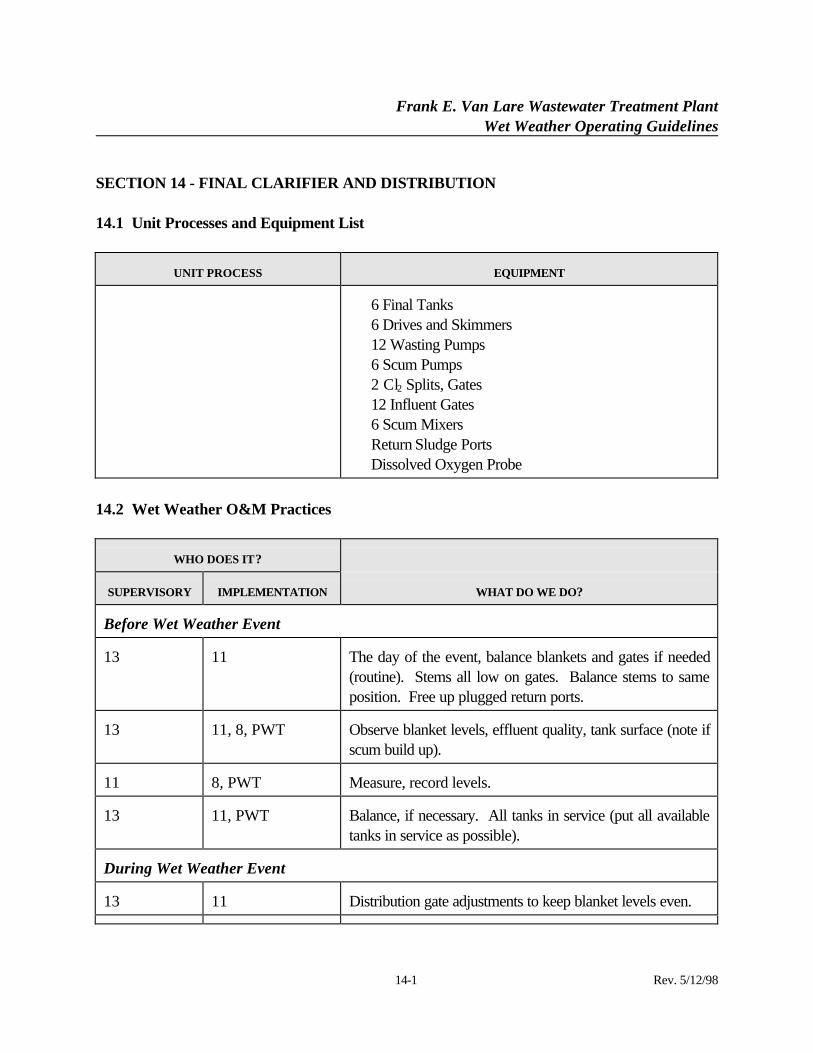
SECTION 14 - FINAL CLARIFIER AND DISTRIBUTION
14.1 Unit Processes and Equipment List
UNIT PROCESS EQUIPMENT
⋅ 6 Final Tanks⋅ 6 Drives and Skimmers⋅ 12 Wasting Pumps⋅ 6 Scum Pumps⋅ 2 Cl2 Splits, Gates⋅ 12 Influent Gates⋅ 6 Scum Mixers⋅ Return Sludge Ports⋅ Dissolved Oxygen Probe
14.2 Wet Weather O&M Practices
WHO DOES IT?
SUPERVISORY IMPLEMENTATION WHAT DO WE DO?
Before Wet Weather Event
13 11 The day of the event, balance blankets and gates if needed(routine). Stems all low on gates. Balance stems to sameposition. Free up plugged return ports.
13 11, 8, PWT Observe blanket levels, effluent quality, tank surface (note ifscum build up).
11 8, PWT Measure, record levels.
13 11, PWT Balance, if necessary. All tanks in service (put all availabletanks in service as possible).
During Wet Weather Event
13 11 Distribution gate adjustments to keep blanket levels even.
Frank E. Van Lare Wastewater Treatment PlantWet Weather Operating Guidelines
14-2 Rev. 5/12/98
WHO DOES IT?
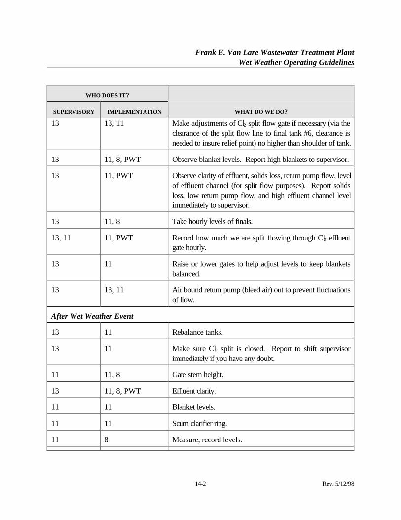
SUPERVISORY IMPLEMENTATION WHAT DO WE DO?
13 13, 11 Make adjustments of Cl2 split flow gate if necessary (via theclearance of the split flow line to final tank #6, clearance isneeded to insure relief point) no higher than shoulder of tank.
13 11, 8, PWT Observe blanket levels. Report high blankets to supervisor.
13 11, PWT Observe clarity of effluent, solids loss, return pump flow, levelof effluent channel (for split flow purposes). Report solidsloss, low return pump flow, and high effluent channel levelimmediately to supervisor.
13 11, 8 Take hourly levels of finals.
13, 11 11, PWT Record how much we are split flowing through Cl2 effluentgate hourly.
13 11 Raise or lower gates to help adjust levels to keep blanketsbalanced.
13 13, 11 Air bound return pump (bleed air) out to prevent fluctuationsof flow.
After Wet Weather Event
13 11 Rebalance tanks.
13 11 Make sure Cl2 split is closed. Report to shift supervisorimmediately if you have any doubt.
11 11, 8 Gate stem height.
13 11, 8, PWT Effluent clarity.
11 11 Blanket levels.
11 11 Scum clarifier ring.
11 8 Measure, record levels.
Frank E. Van Lare Wastewater Treatment PlantWet Weather Operating Guidelines
14-3 Rev. 5/12/98
WHO DOES IT?
SUPERVISORY IMPLEMENTATION WHAT DO WE DO?
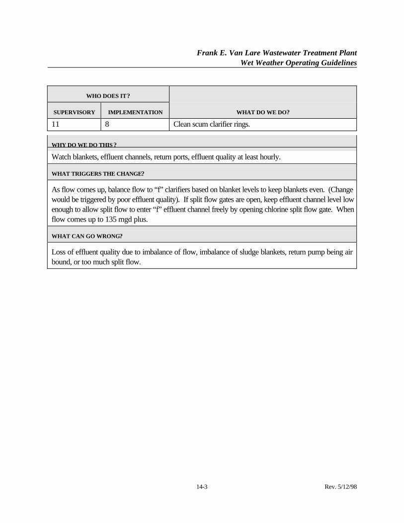
11 8 Clean scum clarifier rings.
WHY DO WE DO THIS ?
Watch blankets, effluent channels, return ports, effluent quality at least hourly.
WHAT TRIGGERS THE CHANGE?
As flow comes up, balance flow to “f” clarifiers based on blanket levels to keep blankets even. (Changewould be triggered by poor effluent quality). If split flow gates are open, keep effluent channel level lowenough to allow split flow to enter “f” effluent channel freely by opening chlorine split flow gate. Whenflow comes up to 135 mgd plus.
WHAT CAN GO WRONG?
Loss of effluent quality due to imbalance of flow, imbalance of sludge blankets, return pump being airbound, or too much split flow.
Frank E. Van Lare Wastewater Treatment PlantWet Weather Operating Guidelines
15-1 Rev. 5/12/98
SECTION 15 - CHLORINATION
15.1 Unit Processes and Equipment List
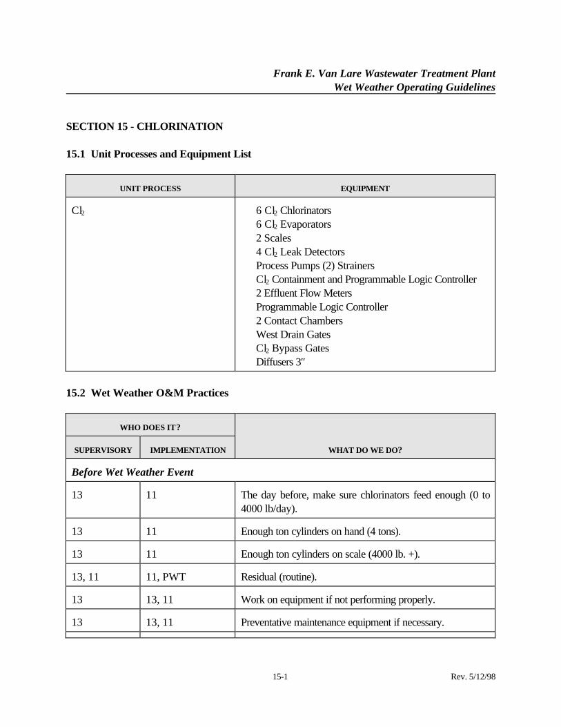
UNIT PROCESS EQUIPMENT
Cl2 ⋅ 6 Cl2 Chlorinators⋅ 6 Cl2 Evaporators⋅ 2 Scales⋅ 4 Cl2 Leak Detectors⋅ Process Pumps (2) Strainers⋅ Cl2 Containment and Programmable Logic Controller⋅ 2 Effluent Flow Meters⋅ Programmable Logic Controller⋅ 2 Contact Chambers⋅ West Drain Gates⋅ Cl2 Bypass Gates⋅ Diffusers 3″
15.2 Wet Weather O&M Practices
WHO DOES IT?
SUPERVISORY IMPLEMENTATION WHAT DO WE DO?
Before Wet Weather Event
13 11 The day before, make sure chlorinators feed enough (0 to4000 lb/day).
13 11 Enough ton cylinders on hand (4 tons).
13 11 Enough ton cylinders on scale (4000 lb. +).
13, 11 11, PWT Residual (routine).
13 13, 11 Work on equipment if not performing properly.
13 13, 11 Preventative maintenance equipment if necessary.
Frank E. Van Lare Wastewater Treatment PlantWet Weather Operating Guidelines
15-2 Rev. 5/12/98
WHO DOES IT?
SUPERVISORY IMPLEMENTATION WHAT DO WE DO?
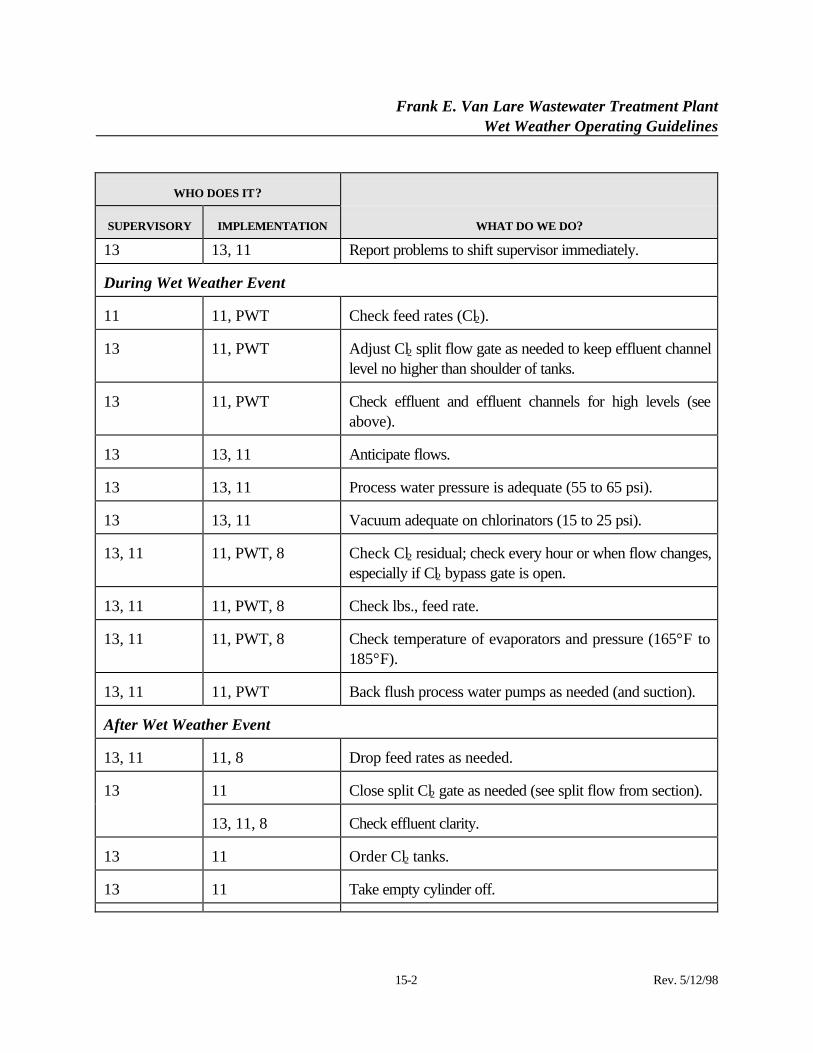
13 13, 11 Report problems to shift supervisor immediately.
During Wet Weather Event
11 11, PWT Check feed rates (Cl2).
13 11, PWT Adjust Cl2 split flow gate as needed to keep effluent channellevel no higher than shoulder of tanks.
13 11, PWT Check effluent and effluent channels for high levels (seeabove).
13 13, 11 Anticipate flows.
13 13, 11 Process water pressure is adequate (55 to 65 psi).
13 13, 11 Vacuum adequate on chlorinators (15 to 25 psi).
13, 11 11, PWT, 8 Check Cl2 residual; check every hour or when flow changes,especially if Cl2 bypass gate is open.
13, 11 11, PWT, 8 Check lbs., feed rate.
13, 11 11, PWT, 8 Check temperature of evaporators and pressure (165°F to185°F).
13, 11 11, PWT Back flush process water pumps as needed (and suction).
After Wet Weather Event
13, 11 11, 8 Drop feed rates as needed.
11 Close split Cl2 gate as needed (see split flow from section).13
13, 11, 8 Check effluent clarity.
13 11 Order Cl2 tanks.
13 11 Take empty cylinder off.
Frank E. Van Lare Wastewater Treatment PlantWet Weather Operating Guidelines
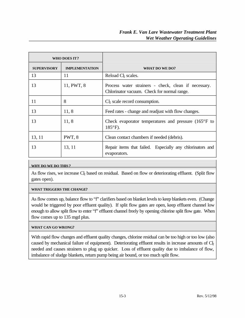
15-3 Rev. 5/12/98
WHO DOES IT?
SUPERVISORY IMPLEMENTATION WHAT DO WE DO?
13 11 Reload Cl2 scales.
13 11, PWT, 8 Process water strainers - check, clean if necessary. Chlorinator vacuum. Check for normal range.
11 8 Cl2 scale record consumption.
13 11, 8 Feed rates - change and readjust with flow changes.
13 11, 8 Check evaporator temperatures and pressure (165°F to185°F).
13, 11 PWT, 8 Clean contact chambers if needed (debris).
13 13, 11 Repair items that failed. Especially any chlorinators andevaporators.
WHY DO WE DO THIS ?
As flow rises, we increase Cl2 based on residual. Based on flow or deteriorating effluent. (Split flowgates open).
WHAT TRIGGERS THE CHANGE?
As flow comes up, balance flow to “f” clarifiers based on blanket levels to keep blankets even. (Changewould be triggered by poor effluent quality). If split flow gates are open, keep effluent channel lowenough to allow split flow to enter “f” effluent channel freely by opening chlorine split flow gate. Whenflow comes up to 135 mgd plus.
WHAT CAN GO WRONG?
With rapid flow changes and effluent quality changes, chlorine residual can be too high or too low (alsocaused by mechanical failure of equipment). Deteriorating effluent results in increase amounts of Cl2needed and causes strainers to plug up quicker. Loss of effluent quality due to imbalance of flow,imbalance of sludge blankets, return pump being air bound, or too much split flow.
Frank E. Van Lare Wastewater Treatment PlantWet Weather Operating Guidelines
16-1 Rev. 5/12/98
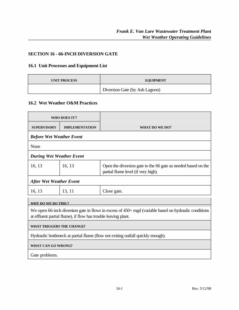
SECTION 16 - 66-INCH DIVERSION GATE
16.1 Unit Processes and Equipment List
UNIT PROCESS EQUIPMENT
Diversion Gate (by Ash Lagoon)
16.2 Wet Weather O&M Practices
WHO DOES IT?
SUPERVISORY IMPLEMENTATION WHAT DO WE DO?
Before Wet Weather Event
None
During Wet Weather Event
16, 13 16, 13 Open the diversion gate to the 66 gate as needed based on thepartial flume level (if very high).
After Wet Weather Event
16, 13 13, 11 Close gate.
WHY DO WE DO THIS ?
We open 66-inch diversion gate in flows in excess of 450+ mgd (variable based on hydraulic conditionsat effluent partial flume), if flow has trouble leaving plant.
WHAT TRIGGERS THE CHANGE?
Hydraulic bottleneck at partial flume (flow not exiting outfall quickly enough).
WHAT CAN GO WRONG?
Gate problems.
Frank E. Van Lare Wastewater Treatment PlantWet Weather Operating Guidelines
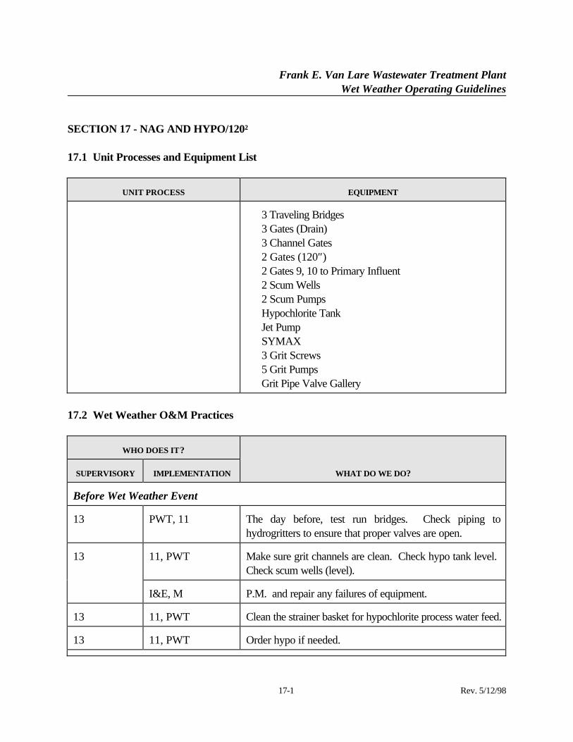
17-1 Rev. 5/12/98
SECTION 17 - NAG AND HYPO/120″
17.1 Unit Processes and Equipment List
UNIT PROCESS EQUIPMENT
⋅ 3 Traveling Bridges⋅ 3 Gates (Drain)⋅ 3 Channel Gates⋅ 2 Gates (120″)⋅ 2 Gates 9, 10 to Primary Influent⋅ 2 Scum Wells⋅ 2 Scum Pumps⋅ Hypochlorite Tank⋅ Jet Pump⋅ SYMAX⋅ 3 Grit Screws⋅ 5 Grit Pumps⋅ Grit Pipe Valve Gallery
17.2 Wet Weather O&M Practices
WHO DOES IT?
SUPERVISORY IMPLEMENTATION WHAT DO WE DO?
Before Wet Weather Event
13 PWT, 11 The day before, test run bridges. Check piping tohydrogritters to ensure that proper valves are open.
11, PWT Make sure grit channels are clean. Check hypo tank level. Check scum wells (level).
13
I&E, M P.M. and repair any failures of equipment.
13 11, PWT Clean the strainer basket for hypochlorite process water feed.
13 11, PWT Order hypo if needed.
Frank E. Van Lare Wastewater Treatment PlantWet Weather Operating Guidelines
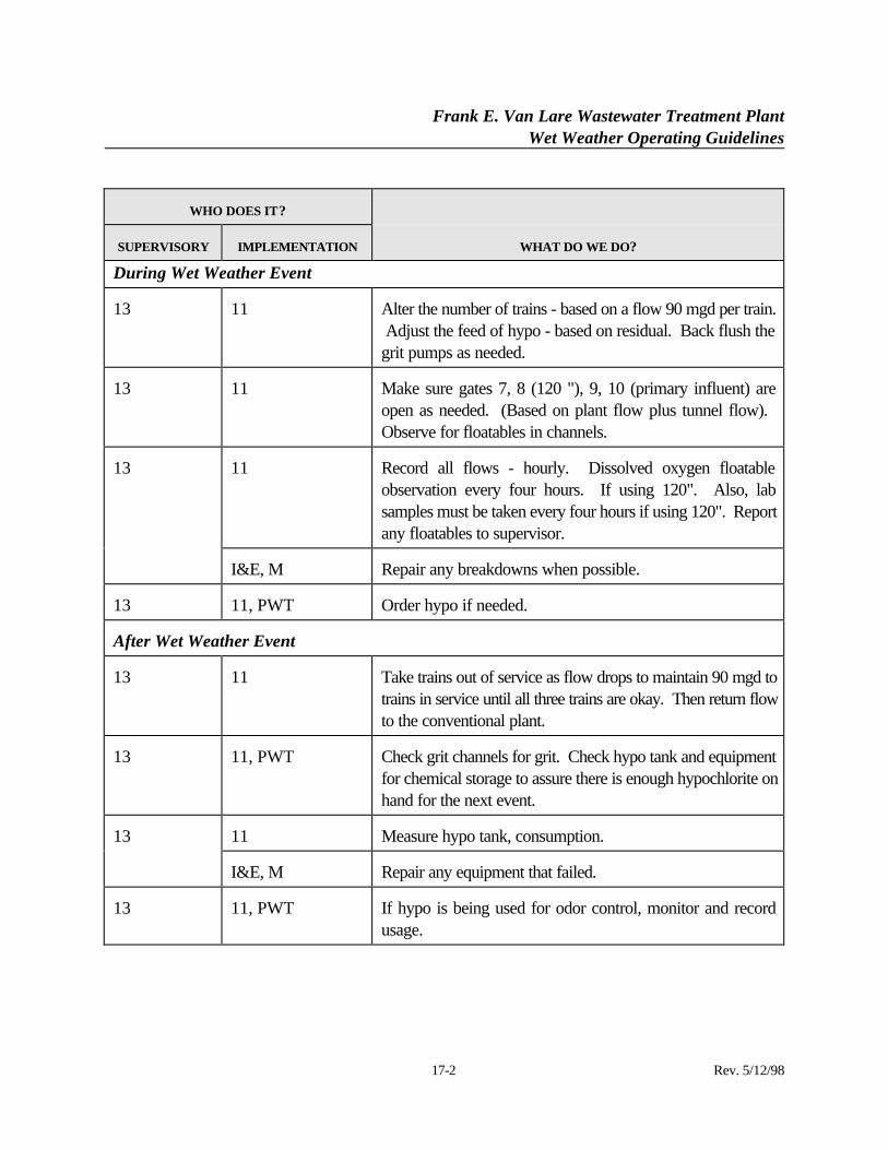
17-2 Rev. 5/12/98
WHO DOES IT?
SUPERVISORY IMPLEMENTATION WHAT DO WE DO?
During Wet Weather Event
13 11 Alter the number of trains - based on a flow 90 mgd per train. Adjust the feed of hypo - based on residual. Back flush thegrit pumps as needed.
13 11 Make sure gates 7, 8 (120 "), 9, 10 (primary influent) areopen as needed. (Based on plant flow plus tunnel flow). Observe for floatables in channels.
11 Record all flows - hourly. Dissolved oxygen floatableobservation every four hours. If using 120". Also, labsamples must be taken every four hours if using 120". Reportany floatables to supervisor.
13
I&E, M Repair any breakdowns when possible.
13 11, PWT Order hypo if needed.
After Wet Weather Event
13 11 Take trains out of service as flow drops to maintain 90 mgd totrains in service until all three trains are okay. Then return flowto the conventional plant.
13 11, PWT Check grit channels for grit. Check hypo tank and equipmentfor chemical storage to assure there is enough hypochlorite onhand for the next event.
11 Measure hypo tank, consumption.13
I&E, M Repair any equipment that failed.
13 11, PWT If hypo is being used for odor control, monitor and recordusage.
Frank E. Van Lare Wastewater Treatment PlantWet Weather Operating Guidelines
SECTION 17 (Continued):
17-3 Rev. 5/12/98
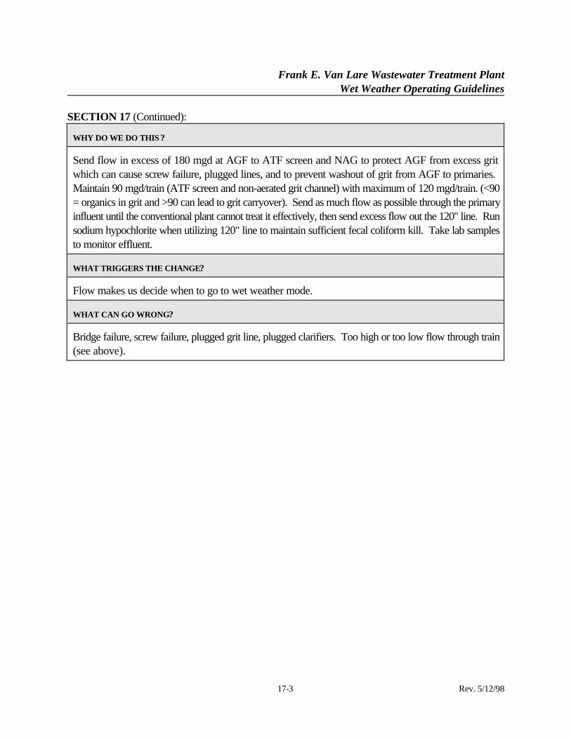
WHY DO WE DO THIS ?
Send flow in excess of 180 mgd at AGF to ATF screen and NAG to protect AGF from excess gritwhich can cause screw failure, plugged lines, and to prevent washout of grit from AGF to primaries. Maintain 90 mgd/train (ATF screen and non-aerated grit channel) with maximum of 120 mgd/train. (<90= organics in grit and >90 can lead to grit carryover). Send as much flow as possible through the primaryinfluent until the conventional plant cannot treat it effectively, then send excess flow out the 120" line. Runsodium hypochlorite when utilizing 120" line to maintain sufficient fecal coliform kill. Take lab samplesto monitor effluent.
WHAT TRIGGERS THE CHANGE?
Flow makes us decide when to go to wet weather mode.
WHAT CAN GO WRONG?
Bridge failure, screw failure, plugged grit line, plugged clarifiers. Too high or too low flow through train(see above).
Frank E. Van Lare Wastewater Treatment PlantWet Weather Operating Guidelines
18-1 Rev. 5/12/98
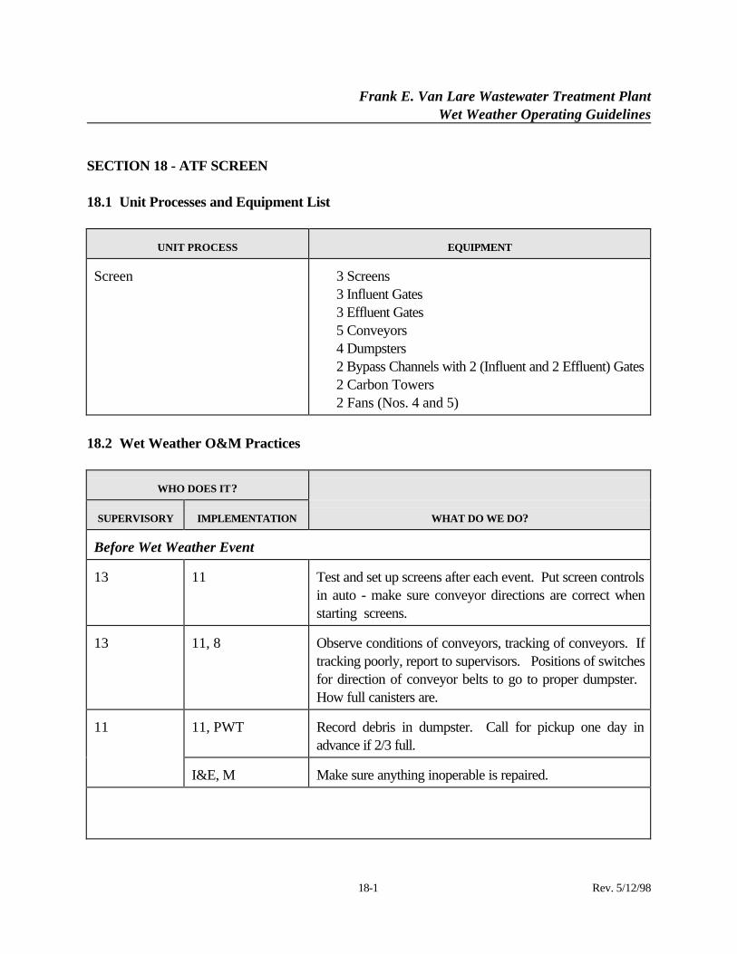
SECTION 18 - ATF SCREEN
18.1 Unit Processes and Equipment List
UNIT PROCESS EQUIPMENT
Screen ⋅ 3 Screens⋅ 3 Influent Gates⋅ 3 Effluent Gates⋅ 5 Conveyors⋅ 4 Dumpsters⋅ 2 Bypass Channels with 2 (Influent and 2 Effluent) Gates⋅ 2 Carbon Towers⋅ 2 Fans (Nos. 4 and 5)
18.2 Wet Weather O&M Practices
WHO DOES IT?
SUPERVISORY IMPLEMENTATION WHAT DO WE DO?
Before Wet Weather Event
13 11 Test and set up screens after each event. Put screen controlsin auto - make sure conveyor directions are correct whenstarting screens.
13 11, 8 Observe conditions of conveyors, tracking of conveyors. Iftracking poorly, report to supervisors. Positions of switchesfor direction of conveyor belts to go to proper dumpster. How full canisters are.
11, PWT Record debris in dumpster. Call for pickup one day inadvance if 2/3 full.
11
I&E, M Make sure anything inoperable is repaired.
Frank E. Van Lare Wastewater Treatment PlantWet Weather Operating Guidelines
18-2 Rev. 5/12/98
WHO DOES IT?
SUPERVISORY IMPLEMENTATION WHAT DO WE DO?
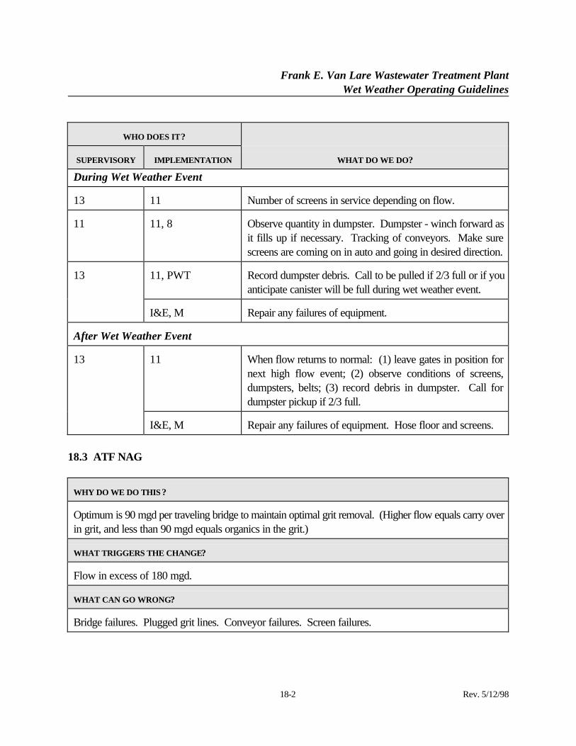
During Wet Weather Event
13 11 Number of screens in service depending on flow.
11 11, 8 Observe quantity in dumpster. Dumpster - winch forward asit fills up if necessary. Tracking of conveyors. Make surescreens are coming on in auto and going in desired direction.
11, PWT Record dumpster debris. Call to be pulled if 2/3 full or if youanticipate canister will be full during wet weather event.
13
I&E, M Repair any failures of equipment.
After Wet Weather Event
11 When flow returns to normal: (1) leave gates in position fornext high flow event; (2) observe conditions of screens,dumpsters, belts; (3) record debris in dumpster. Call fordumpster pickup if 2/3 full.
13
I&E, M Repair any failures of equipment. Hose floor and screens.
18.3 ATF NAG
WHY DO WE DO THIS ?
Optimum is 90 mgd per traveling bridge to maintain optimal grit removal. (Higher flow equals carry overin grit, and less than 90 mgd equals organics in the grit.)
WHAT TRIGGERS THE CHANGE?
Flow in excess of 180 mgd.
WHAT CAN GO WRONG?
Bridge failures. Plugged grit lines. Conveyor failures. Screen failures.
Frank E. Van Lare Wastewater Treatment PlantWet Weather Operating Guidelines
SECTION 18 (Continued):
18-3 Rev. 5/12/98
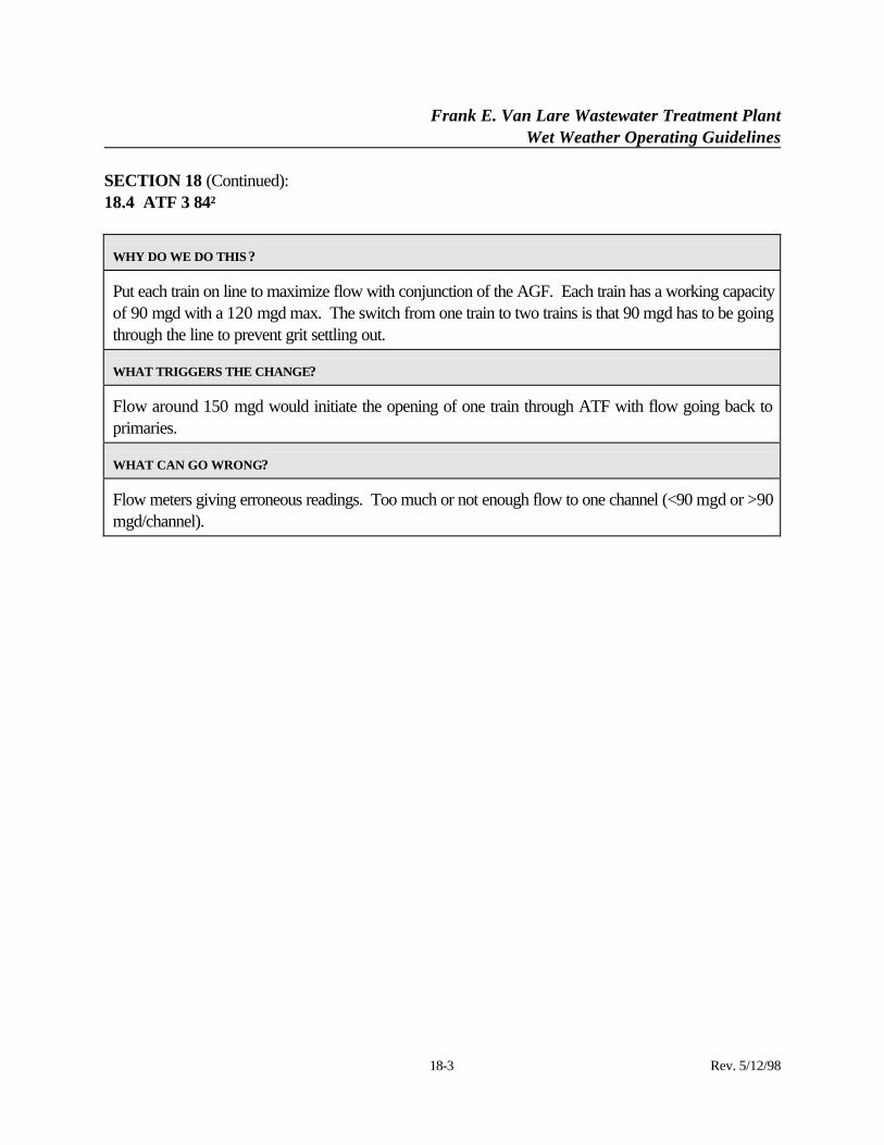
18.4 ATF 3 84″
WHY DO WE DO THIS ?
Put each train on line to maximize flow with conjunction of the AGF. Each train has a working capacityof 90 mgd with a 120 mgd max. The switch from one train to two trains is that 90 mgd has to be goingthrough the line to prevent grit settling out.
WHAT TRIGGERS THE CHANGE?
Flow around 150 mgd would initiate the opening of one train through ATF with flow going back toprimaries.
WHAT CAN GO WRONG?
Flow meters giving erroneous readings. Too much or not enough flow to one channel (<90 mgd or >90mgd/channel).
Frank E. Van Lare Wastewater Treatment PlantWet Weather Operating Guidelines
19-1 Rev. 5/12/98
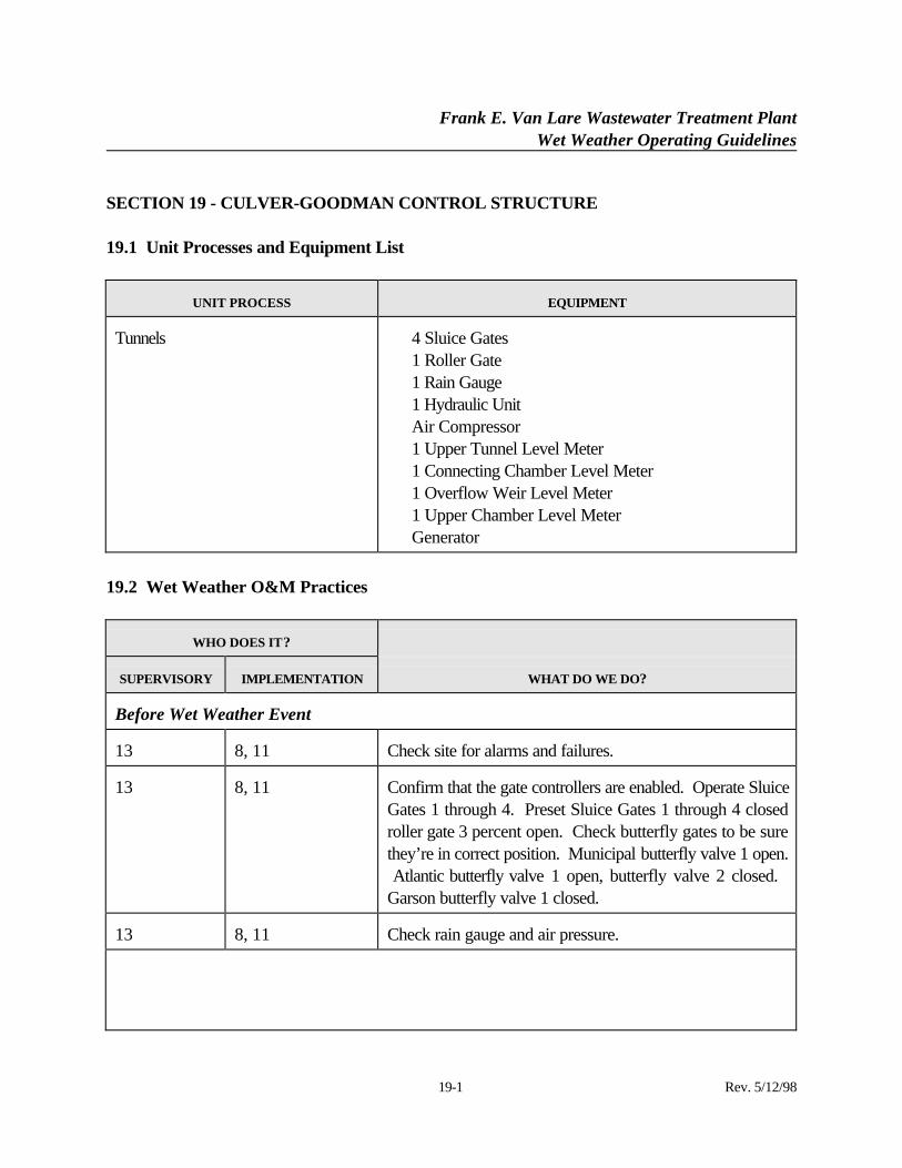
SECTION 19 - CULVER-GOODMAN CONTROL STRUCTURE
19.1 Unit Processes and Equipment List
UNIT PROCESS EQUIPMENT
Tunnels ⋅ 4 Sluice Gates⋅ 1 Roller Gate⋅ 1 Rain Gauge⋅ 1 Hydraulic Unit⋅ Air Compressor⋅ 1 Upper Tunnel Level Meter⋅ 1 Connecting Chamber Level Meter⋅ 1 Overflow Weir Level Meter⋅ 1 Upper Chamber Level Meter⋅ Generator
19.2 Wet Weather O&M Practices
WHO DOES IT?
SUPERVISORY IMPLEMENTATION WHAT DO WE DO?
Before Wet Weather Event
13 8, 11 Check site for alarms and failures.
13 8, 11 Confirm that the gate controllers are enabled. Operate SluiceGates 1 through 4. Preset Sluice Gates 1 through 4 closedroller gate 3 percent open. Check butterfly gates to be surethey’re in correct position. Municipal butterfly valve 1 open. Atlantic butterfly valve 1 open, butterfly valve 2 closed. Garson butterfly valve 1 closed.
13 8, 11 Check rain gauge and air pressure.
Frank E. Van Lare Wastewater Treatment PlantWet Weather Operating Guidelines
19-2 Rev. 5/12/98
WHO DOES IT?
SUPERVISORY IMPLEMENTATION WHAT DO WE DO?
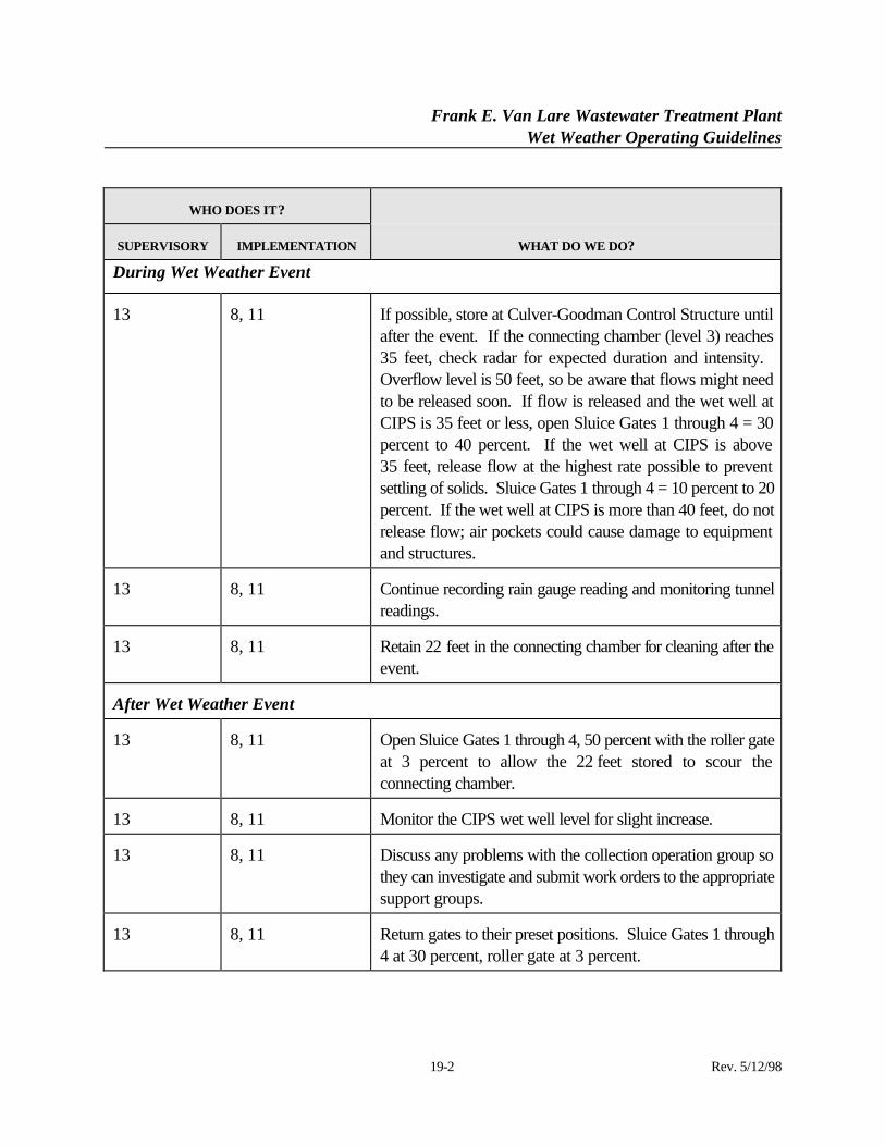
During Wet Weather Event
13 8, 11 If possible, store at Culver-Goodman Control Structure untilafter the event. If the connecting chamber (level 3) reaches35 feet, check radar for expected duration and intensity. Overflow level is 50 feet, so be aware that flows might needto be released soon. If flow is released and the wet well atCIPS is 35 feet or less, open Sluice Gates 1 through 4 = 30percent to 40 percent. If the wet well at CIPS is above35 feet, release flow at the highest rate possible to preventsettling of solids. Sluice Gates 1 through 4 = 10 percent to 20percent. If the wet well at CIPS is more than 40 feet, do notrelease flow; air pockets could cause damage to equipmentand structures.
13 8, 11 Continue recording rain gauge reading and monitoring tunnelreadings.
13 8, 11 Retain 22 feet in the connecting chamber for cleaning after theevent.
After Wet Weather Event
13 8, 11 Open Sluice Gates 1 through 4, 50 percent with the roller gateat 3 percent to allow the 22 feet stored to scour theconnecting chamber.
13 8, 11 Monitor the CIPS wet well level for slight increase.
13 8, 11 Discuss any problems with the collection operation group sothey can investigate and submit work orders to the appropriatesupport groups.
13 8, 11 Return gates to their preset positions. Sluice Gates 1 through4 at 30 percent, roller gate at 3 percent.
Frank E. Van Lare Wastewater Treatment PlantWet Weather Operating Guidelines
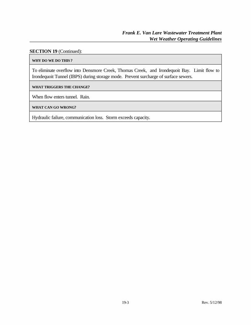
SECTION 19 (Continued):
19-3 Rev. 5/12/98
WHY DO WE DO THIS ?
To eliminate overflow into Densmore Creek, Thomas Creek, and Irondequoit Bay. Limit flow toIrondequoit Tunnel (IBPS) during storage mode. Prevent surcharge of surface sewers.
WHAT TRIGGERS THE CHANGE?
When flow enters tunnel. Rain.
WHAT CAN GO WRONG?
Hydraulic failure, communication loss. Storm exceeds capacity.
Frank E. Van Lare Wastewater Treatment PlantWet Weather Operating Guidelines
20-1 Rev. 5/12/98
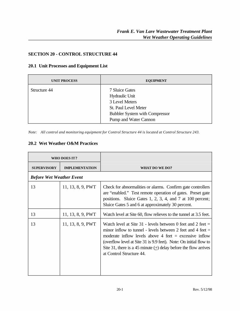
SECTION 20 - CONTROL STRUCTURE 44
20.1 Unit Processes and Equipment List
UNIT PROCESS EQUIPMENT
Structure 44 ⋅ 7 Sluice Gates⋅ Hydraulic Unit⋅ 3 Level Meters⋅ St. Paul Level Meter⋅ Bubbler System with Compressor⋅ Pump and Water Cannon
Note: All control and monitoring equipment for Control Structure 44 is located at Control Structure 243.
20.2 Wet Weather O&M Practices
WHO DOES IT?
SUPERVISORY IMPLEMENTATION WHAT DO WE DO?
Before Wet Weather Event
13 11, 13, 8, 9, PWT Check for abnormalities or alarms. Confirm gate controllersare “enabled.” Test remote operation of gates. Preset gatepositions. Sluice Gates 1, 2, 3, 4, and 7 at 100 percent;Sluice Gates 5 and 6 at approximately 30 percent.
13 11, 13, 8, 9, PWT Watch level at Site 60, flow relieves to the tunnel at 3.5 feet.
13 11, 13, 8, 9, PWT Watch level at Site 31 - levels between 0 feet and 2 feet =minor inflow to tunnel - levels between 2 feet and 4 feet =moderate inflow levels above 4 feet = excessive inflow(overflow level at Site 31 is 9.9 feet). Note: On initial flow toSite 31, there is a 45 minute (+) delay before the flow arrivesat Control Structure 44.
Frank E. Van Lare Wastewater Treatment PlantWet Weather Operating Guidelines
20-2 Rev. 5/12/98
WHO DOES IT?
SUPERVISORY IMPLEMENTATION WHAT DO WE DO?
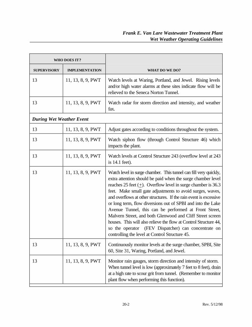
13 11, 13, 8, 9, PWT Watch levels at Waring, Portland, and Jewel. Rising levelsand/or high water alarms at these sites indicate flow will berelieved to the Seneca Norton Tunnel.
13 11, 13, 8, 9, PWT Watch radar for storm direction and intensity, and weatherfax.
During Wet Weather Event
13 11, 13, 8, 9, PWT Adjust gates according to conditions throughout the system.
13 11, 13, 8, 9, PWT Watch siphon flow (through Control Structure 46) whichimpacts the plant.
13 11, 13, 8, 9, PWT Watch levels at Control Structure 243 (overflow level at 243is 14.1 feet).
13 11, 13, 8, 9, PWT Watch level in surge chamber. This tunnel can fill very quickly,extra attention should be paid when the surge chamber levelreaches 25 feet (+). Overflow level in surge chamber is 36.3feet. Make small gate adjustments to avoid surges, waves,and overflows at other structures. If the rain event is excessiveor long term, flow diversions out of SPBI and into the LakeAvenue Tunnel, this can be performed at Front Street,Malvern Street, and both Glenwood and Cliff Street screenhouses. This will also relieve the flow at Control Structure 44,so the operator (FEV Dispatcher) can concentrate oncontrolling the level at Control Structure 45.
13 11, 13, 8, 9, PWT Continuously monitor levels at the surge chamber, SPBI, Site60, Site 31, Waring, Portland, and Jewel.
13 11, 13, 8, 9, PWT Monitor rain gauges, storm direction and intensity of storm. When tunnel level is low (approximately 7 feet to 8 feet), drainat a high rate to scour grit from tunnel. (Remember to monitorplant flow when performing this function).
Frank E. Van Lare Wastewater Treatment PlantWet Weather Operating Guidelines
20-3 Rev. 5/12/98
WHO DOES IT?
SUPERVISORY IMPLEMENTATION WHAT DO WE DO?
After Wet Weather Event
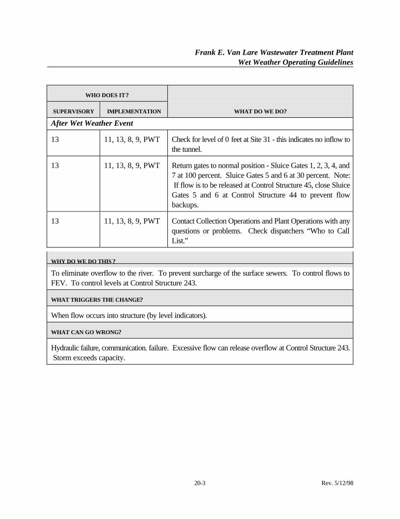
13 11, 13, 8, 9, PWT Check for level of 0 feet at Site 31 - this indicates no inflow tothe tunnel.
13 11, 13, 8, 9, PWT Return gates to normal position - Sluice Gates 1, 2, 3, 4, and7 at 100 percent. Sluice Gates 5 and 6 at 30 percent. Note: If flow is to be released at Control Structure 45, close SluiceGates 5 and 6 at Control Structure 44 to prevent flowbackups.
13 11, 13, 8, 9, PWT Contact Collection Operations and Plant Operations with anyquestions or problems. Check dispatchers “Who to CallList.”
WHY DO WE DO THIS ?
To eliminate overflow to the river. To prevent surcharge of the surface sewers. To control flows toFEV. To control levels at Control Structure 243.
WHAT TRIGGERS THE CHANGE?
When flow occurs into structure (by level indicators).
WHAT CAN GO WRONG?
Hydraulic failure, communication. failure. Excessive flow can release overflow at Control Structure 243. Storm exceeds capacity.
Frank E. Van Lare Wastewater Treatment PlantWet Weather Operating Guidelines
21-1 Rev. 5/12/98
SECTION 21 - CONTROL STRUCTURE 45
21.1 Unit Processes and Equipment List
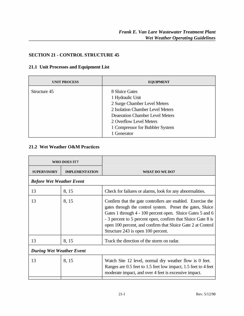
UNIT PROCESS EQUIPMENT
Structure 45 ⋅ 8 Sluice Gates⋅ 1 Hydraulic Unit⋅ 2 Surge Chamber Level Meters⋅ 2 Isolation Chamber Level Meters⋅ Deaeration Chamber Level Meters⋅ 2 Overflow Level Meters⋅ 1 Compressor for Bubbler System⋅ 1 Generator
21.2 Wet Weather O&M Practices
WHO DOES IT?
SUPERVISORY IMPLEMENTATION WHAT DO WE DO?
Before Wet Weather Event
13 8, 15 Check for failures or alarms, look for any abnormalities.
13 8, 15 Confirm that the gate controllers are enabled. Exercise thegates through the control system. Preset the gates, SluiceGates 1 through 4 - 100 percent open. Sluice Gates 5 and 6- 3 percent to 5 percent open, confirm that Sluice Gate 8 isopen 100 percent, and confirm that Sluice Gate 2 at ControlStructure 243 is open 100 percent.
13 8, 15 Track the direction of the storm on radar.
During Wet Weather Event
13 8, 15 Watch Site 12 level, normal dry weather flow is 0 feet. Ranges are 0.5 feet to 1.5 feet low impact, 1.5 feet to 4 feetmoderate impact, and over 4 feet is excessive impact.
Frank E. Van Lare Wastewater Treatment PlantWet Weather Operating Guidelines
21-2 Rev. 5/12/98
WHO DOES IT?
SUPERVISORY IMPLEMENTATION WHAT DO WE DO?
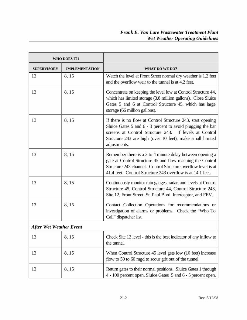
13 8, 15 Watch the level at Front Street normal dry weather is 1.2 feetand the overflow weir to the tunnel is at 4.2 feet.
13 8, 15 Concentrate on keeping the level low at Control Structure 44,which has limited storage (3.8 million gallons). Close SluiceGates 5 and 6 at Control Structure 45, which has largestorage (66 million gallons).
13 8, 15 If there is no flow at Control Structure 243, start openingSluice Gates 5 and 6 - 3 percent to avoid plugging the barscreens at Control Structure 243. If levels at ControlStructure 243 are high (over 10 feet), make small limitedadjustments.
13 8, 15 Remember there is a 3 to 4 minute delay between opening agate at Control Structure 45 and flow reaching the ControlStructure 243 channel. Control Structure overflow level is at41.4 feet. Control Structure 243 overflow is at 14.1 feet.
13 8, 15 Continuously monitor rain gauges, radar, and levels at ControlStructure 45, Control Structure 44, Control Structure 243,Site 12, Front Street, St. Paul Blvd. Interceptor, and FEV.
13 8, 15 Contact Collection Operations for recommendations orinvestigation of alarms or problems. Check the “Who ToCall” dispatcher list.
After Wet Weather Event
13 8, 15 Check Site 12 level - this is the best indicator of any inflow tothe tunnel.
13 8, 15 When Control Structure 45 level gets low (10 feet) increaseflow to 50 to 60 mgd to scour grit out of the tunnel.
13 8, 15 Return gates to their normal positions. Sluice Gates 1 through4 - 100 percent open, Sluice Gates 5 and 6 - 5 percent open.
Frank E. Van Lare Wastewater Treatment PlantWet Weather Operating Guidelines
21-3 Rev. 5/12/98
WHO DOES IT?
SUPERVISORY IMPLEMENTATION WHAT DO WE DO?
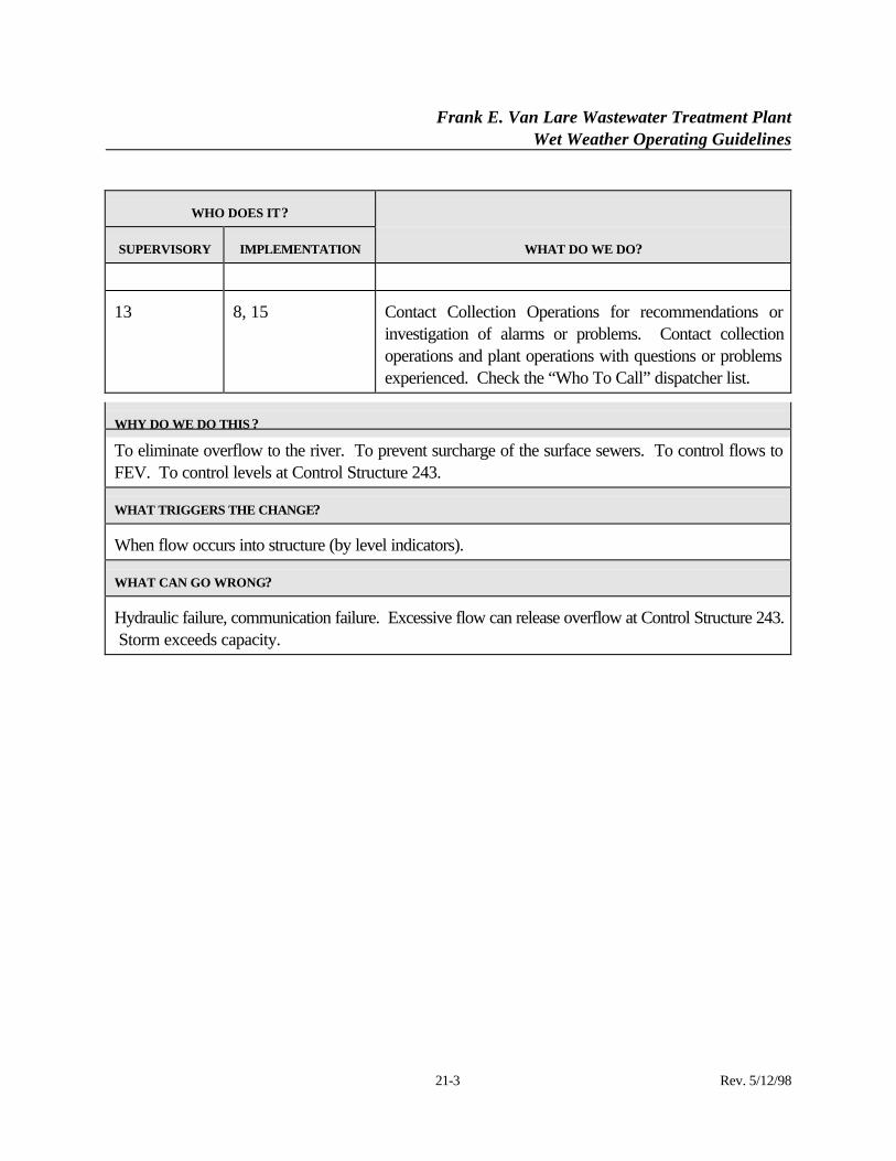
13 8, 15 Contact Collection Operations for recommendations orinvestigation of alarms or problems. Contact collectionoperations and plant operations with questions or problemsexperienced. Check the “Who To Call” dispatcher list.
WHY DO WE DO THIS ?
To eliminate overflow to the river. To prevent surcharge of the surface sewers. To control flows toFEV. To control levels at Control Structure 243.
WHAT TRIGGERS THE CHANGE?
When flow occurs into structure (by level indicators).
WHAT CAN GO WRONG?
Hydraulic failure, communication failure. Excessive flow can release overflow at Control Structure 243. Storm exceeds capacity.
Frank E. Van Lare Wastewater Treatment PlantWet Weather Operating Guidelines
22-1 Rev. 5/12/98
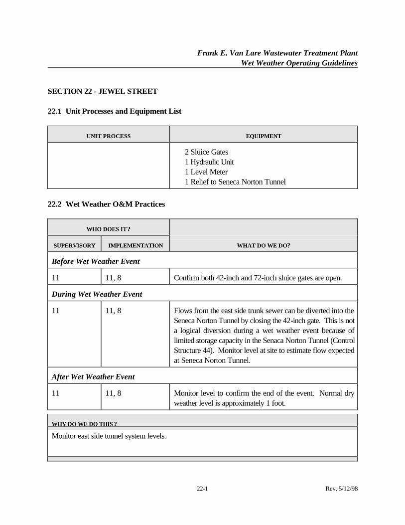
SECTION 22 - JEWEL STREET
22.1 Unit Processes and Equipment List
UNIT PROCESS EQUIPMENT
⋅ 2 Sluice Gates⋅ 1 Hydraulic Unit⋅ 1 Level Meter⋅ 1 Relief to Seneca Norton Tunnel
22.2 Wet Weather O&M Practices
WHO DOES IT?
SUPERVISORY IMPLEMENTATION WHAT DO WE DO?
Before Wet Weather Event
11 11, 8 Confirm both 42-inch and 72-inch sluice gates are open.
During Wet Weather Event
11 11, 8 Flows from the east side trunk sewer can be diverted into theSeneca Norton Tunnel by closing the 42-inch gate. This is nota logical diversion during a wet weather event because oflimited storage capacity in the Senaca Norton Tunnel (ControlStructure 44). Monitor level at site to estimate flow expectedat Seneca Norton Tunnel.
After Wet Weather Event
11 11, 8 Monitor level to confirm the end of the event. Normal dryweather level is approximately 1 foot.
WHY DO WE DO THIS ?
Monitor east side tunnel system levels.
Frank E. Van Lare Wastewater Treatment PlantWet Weather Operating Guidelines
22-2 Rev. 5/12/98
WHAT TRIGGERS THE CHANGE?
WHAT CAN GO WRONG?
Gate failure, hydraulic failure, communication failure.
Frank E. Van Lare Wastewater Treatment PlantWet Weather Operating Guidelines
23-1 Rev. 5/12/98
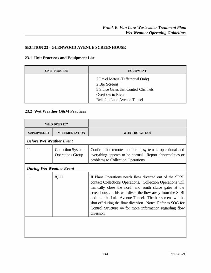
SECTION 23 - GLENWOOD AVENUE SCREENHOUSE
23.1 Unit Processes and Equipment List
UNIT PROCESS EQUIPMENT
⋅ 2 Level Meters (Differential Only)⋅ 2 Bar Screens⋅ 5 Sluice Gates that Control Channels⋅ Overflow to River⋅ Relief to Lake Avenue Tunnel
23.2 Wet Weather O&M Practices
WHO DOES IT?
SUPERVISORY IMPLEMENTATION WHAT DO WE DO?
Before Wet Weather Event
11 Collection SystemOperations Group
Confirm that remote monitoring system is operational andeverything appears to be normal. Report abnormalities orproblems to Collection Operations.
During Wet Weather Event
11 8, 11 If Plant Operations needs flow diverted out of the SPBI,contact Collections Operations. Collection Operations willmanually close the north and south sluice gates at thescreenhouse. This will divert the flow away from the SPBIand into the Lake Avenue Tunnel. The bar screens will beshut off during the flow diversion. Note: Refer to SOG forControl Structure 44 for more information regarding flowdiversion.
Frank E. Van Lare Wastewater Treatment PlantWet Weather Operating Guidelines
23-2 Rev. 5/12/98
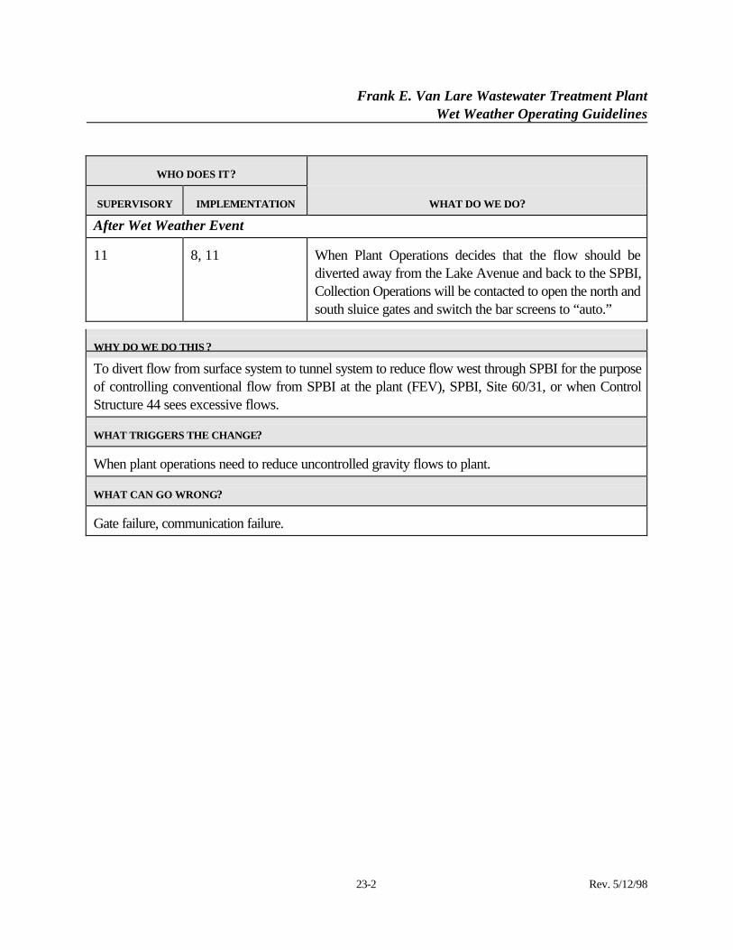
WHO DOES IT?
SUPERVISORY IMPLEMENTATION WHAT DO WE DO?
After Wet Weather Event
11 8, 11 When Plant Operations decides that the flow should bediverted away from the Lake Avenue and back to the SPBI,Collection Operations will be contacted to open the north andsouth sluice gates and switch the bar screens to “auto.”
WHY DO WE DO THIS ?
To divert flow from surface system to tunnel system to reduce flow west through SPBI for the purposeof controlling conventional flow from SPBI at the plant (FEV), SPBI, Site 60/31, or when ControlStructure 44 sees excessive flows.
WHAT TRIGGERS THE CHANGE?
When plant operations need to reduce uncontrolled gravity flows to plant.
WHAT CAN GO WRONG?
Gate failure, communication failure.
Frank E. Van Lare Wastewater Treatment PlantWet Weather Operating Guidelines
24-1 Rev. 5/12/98
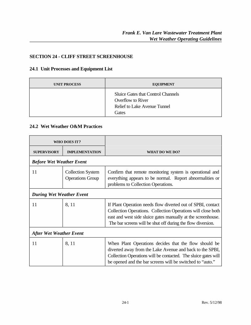
SECTION 24 - CLIFF STREET SCREENHOUSE
24.1 Unit Processes and Equipment List
UNIT PROCESS EQUIPMENT
⋅ Sluice Gates that Control Channels⋅ Overflow to River⋅ Relief to Lake Avenue Tunnel⋅ Gates
24.2 Wet Weather O&M Practices
WHO DOES IT?
SUPERVISORY IMPLEMENTATION WHAT DO WE DO?
Before Wet Weather Event
11 Collection SystemOperations Group
Confirm that remote monitoring system is operational andeverything appears to be normal. Report abnormalities orproblems to Collection Operations.
During Wet Weather Event
11 8, 11 If Plant Operation needs flow diverted out of SPBI, contactCollection Operations. Collection Operations will close botheast and west side sluice gates manually at the screenhouse. The bar screens will be shut off during the flow diversion.
After Wet Weather Event
11 8, 11 When Plant Operations decides that the flow should bediverted away from the Lake Avenue and back to the SPBI,Collection Operations will be contacted. The sluice gates willbe opened and the bar screens will be switched to “auto.”
Frank E. Van Lare Wastewater Treatment PlantWet Weather Operating Guidelines
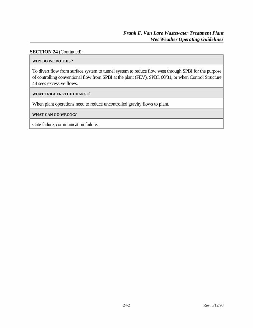
SECTION 24 (Continued):
24-2 Rev. 5/12/98
WHY DO WE DO THIS ?
To divert flow from surface system to tunnel system to reduce flow west through SPBI for the purposeof controlling conventional flow from SPBI at the plant (FEV), SPBI, 60/31, or when Control Structure44 sees excessive flows.
WHAT TRIGGERS THE CHANGE?
When plant operations need to reduce uncontrolled gravity flows to plant.
WHAT CAN GO WRONG?
Gate failure, communication failure.
Frank E. Van Lare Wastewater Treatment PlantWet Weather Operating Guidelines
25-1 Rev. 5/12/98
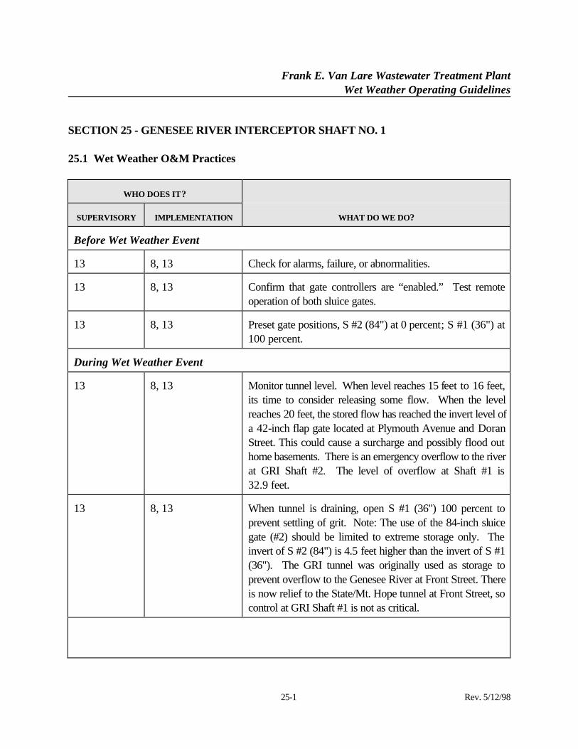
SECTION 25 - GENESEE RIVER INTERCEPTOR SHAFT NO. 1
25.1 Wet Weather O&M Practices
WHO DOES IT?
SUPERVISORY IMPLEMENTATION WHAT DO WE DO?
Before Wet Weather Event
13 8, 13 Check for alarms, failure, or abnormalities.
13 8, 13 Confirm that gate controllers are “enabled.” Test remoteoperation of both sluice gates.
13 8, 13 Preset gate positions, S #2 (84") at 0 percent; S #1 (36") at100 percent.
During Wet Weather Event
13 8, 13 Monitor tunnel level. When level reaches 15 feet to 16 feet,its time to consider releasing some flow. When the levelreaches 20 feet, the stored flow has reached the invert level ofa 42-inch flap gate located at Plymouth Avenue and DoranStreet. This could cause a surcharge and possibly flood outhome basements. There is an emergency overflow to the riverat GRI Shaft #2. The level of overflow at Shaft #1 is32.9 feet.
13 8, 13 When tunnel is draining, open S #1 (36") 100 percent toprevent settling of grit. Note: The use of the 84-inch sluicegate (#2) should be limited to extreme storage only. Theinvert of S #2 (84") is 4.5 feet higher than the invert of S #1(36"). The GRI tunnel was originally used as storage toprevent overflow to the Genesee River at Front Street. Thereis now relief to the State/Mt. Hope tunnel at Front Street, socontrol at GRI Shaft #1 is not as critical.
Frank E. Van Lare Wastewater Treatment PlantWet Weather Operating Guidelines
25-2 Rev. 5/12/98
WHO DOES IT?
SUPERVISORY IMPLEMENTATION WHAT DO WE DO?
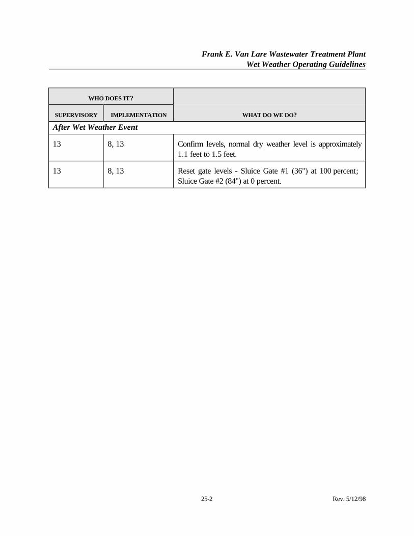
After Wet Weather Event
13 8, 13 Confirm levels, normal dry weather level is approximately1.1 feet to 1.5 feet.
13 8, 13 Reset gate levels - Sluice Gate #1 (36") at 100 percent; Sluice Gate #2 (84") at 0 percent.
Frank E. Van Lare Wastewater Treatment PlantWet Weather Operating Guidelines
26-1 Rev. 5/12/98
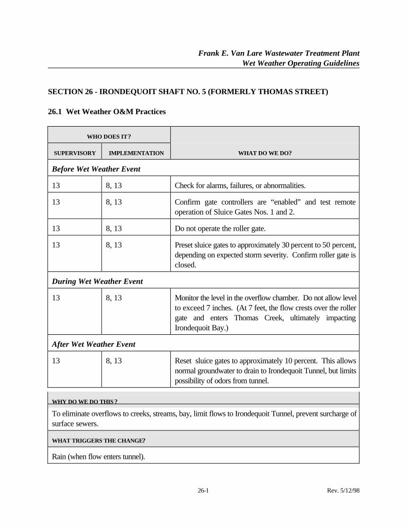
SECTION 26 - IRONDEQUOIT SHAFT NO. 5 (FORMERLY THOMAS STREET)
26.1 Wet Weather O&M Practices
WHO DOES IT?
SUPERVISORY IMPLEMENTATION WHAT DO WE DO?
Before Wet Weather Event
13 8, 13 Check for alarms, failures, or abnormalities.
13 8, 13 Confirm gate controllers are “enabled” and test remoteoperation of Sluice Gates Nos. 1 and 2.
13 8, 13 Do not operate the roller gate.
13 8, 13 Preset sluice gates to approximately 30 percent to 50 percent,depending on expected storm severity. Confirm roller gate isclosed.
During Wet Weather Event
13 8, 13 Monitor the level in the overflow chamber. Do not allow levelto exceed 7 inches. (At 7 feet, the flow crests over the rollergate and enters Thomas Creek, ultimately impactingIrondequoit Bay.)
After Wet Weather Event
13 8, 13 Reset sluice gates to approximately 10 percent. This allowsnormal groundwater to drain to Irondequoit Tunnel, but limitspossibility of odors from tunnel.
WHY DO WE DO THIS ?
To eliminate overflows to creeks, streams, bay, limit flows to Irondequoit Tunnel, prevent surcharge ofsurface sewers.
WHAT TRIGGERS THE CHANGE?
Rain (when flow enters tunnel).
Frank E. Van Lare Wastewater Treatment PlantWet Weather Operating Guidelines
26-2 Rev. 5/12/98
WHAT CAN GO WRONG?
Gate failure, hydraulic failure, communication failure. Storm exceeds capacity.
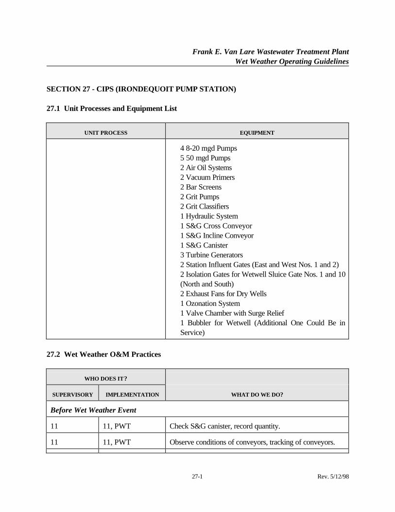
Frank E. Van Lare Wastewater Treatment PlantWet Weather Operating Guidelines
27-1 Rev. 5/12/98
SECTION 27 - CIPS (IRONDEQUOIT PUMP STATION)
27.1 Unit Processes and Equipment List
UNIT PROCESS EQUIPMENT
⋅ 4 8-20 mgd Pumps⋅ 5 50 mgd Pumps⋅ 2 Air Oil Systems⋅ 2 Vacuum Primers⋅ 2 Bar Screens⋅ 2 Grit Pumps⋅ 2 Grit Classifiers⋅ 1 Hydraulic System⋅ 1 S&G Cross Conveyor⋅ 1 S&G Incline Conveyor⋅ 1 S&G Canister⋅ 3 Turbine Generators⋅ 2 Station Influent Gates (East and West Nos. 1 and 2)⋅ 2 Isolation Gates for Wetwell Sluice Gate Nos. 1 and 10
(North and South)⋅ 2 Exhaust Fans for Dry Wells⋅ 1 Ozonation System⋅ 1 Valve Chamber with Surge Relief⋅ 1 Bubbler for Wetwell (Additional One Could Be in
Service)
27.2 Wet Weather O&M Practices
WHO DOES IT?
SUPERVISORY IMPLEMENTATION WHAT DO WE DO?
Before Wet Weather Event
11 11, PWT Check S&G canister, record quantity.
11 11, PWT Observe conditions of conveyors, tracking of conveyors.
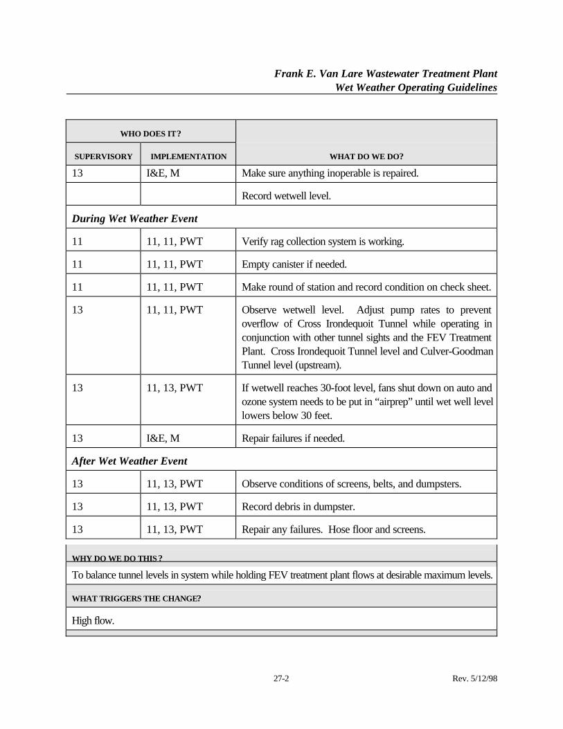
Frank E. Van Lare Wastewater Treatment PlantWet Weather Operating Guidelines
27-2 Rev. 5/12/98
WHO DOES IT?
SUPERVISORY IMPLEMENTATION WHAT DO WE DO?
13 I&E, M Make sure anything inoperable is repaired.
Record wetwell level.
During Wet Weather Event
11 11, 11, PWT Verify rag collection system is working.
11 11, 11, PWT Empty canister if needed.
11 11, 11, PWT Make round of station and record condition on check sheet.
13 11, 11, PWT Observe wetwell level. Adjust pump rates to preventoverflow of Cross Irondequoit Tunnel while operating inconjunction with other tunnel sights and the FEV TreatmentPlant. Cross Irondequoit Tunnel level and Culver-GoodmanTunnel level (upstream).
13 11, 13, PWT If wetwell reaches 30-foot level, fans shut down on auto andozone system needs to be put in “airprep” until wet well levellowers below 30 feet.
13 I&E, M Repair failures if needed.
After Wet Weather Event
13 11, 13, PWT Observe conditions of screens, belts, and dumpsters.
13 11, 13, PWT Record debris in dumpster.
13 11, 13, PWT Repair any failures. Hose floor and screens.
WHY DO WE DO THIS ?
To balance tunnel levels in system while holding FEV treatment plant flows at desirable maximum levels.
WHAT TRIGGERS THE CHANGE?
High flow.
Frank E. Van Lare Wastewater Treatment PlantWet Weather Operating Guidelines
27-3 Rev. 5/12/98
WHAT CAN GO WRONG?
Equipment failures of equipment on equipment list.
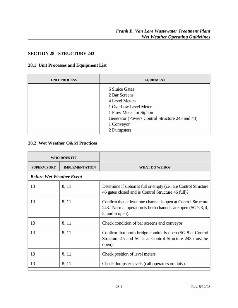
Frank E. Van Lare Wastewater Treatment PlantWet Weather Operating Guidelines
28-1 Rev. 5/12/98
SECTION 28 - STRUCTURE 243
28.1 Unit Processes and Equipment List
UNIT PROCESS EQUIPMENT
⋅ 6 Sluice Gates⋅ 2 Bar Screens⋅ 4 Level Meters⋅ 1 Overflow Level Meter⋅ 1 Flow Meter for Siphon⋅ Generator (Powers Control Structure 243 and 44)⋅ 1 Conveyor⋅ 2 Dumpsters
28.2 Wet Weather O&M Practices
WHO DOES IT?
SUPERVISORY IMPLEMENTATION WHAT DO WE DO?
Before Wet Weather Event
13 8, 11 Determine if siphon is full or empty (i.e., are Control Structure46 gates closed and is Control Structure 46 full)?
13 8, 11 Confirm that at least one channel is open at Control Structure243. Normal operation is both channels are open (SG’s 3, 4,5, and 6 open).
13 8, 11 Check condition of bar screens and conveyor.
13 8, 11 Confirm that north bridge conduit is open (SG 8 at ControlStructure 45 and SG 2 at Control Structure 243 must beopen).
13 8, 11 Check position of level meters.
13 8, 11 Check dumpster levels (call operators on duty).
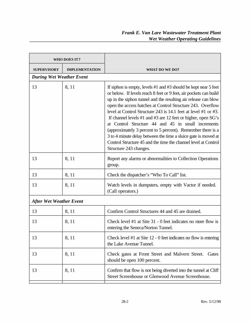
Frank E. Van Lare Wastewater Treatment PlantWet Weather Operating Guidelines
28-2 Rev. 5/12/98
WHO DOES IT?
SUPERVISORY IMPLEMENTATION WHAT DO WE DO?
During Wet Weather Event
13 8, 11 If siphon is empty, levels #1 and #3 should be kept near 5 feetor below. If levels reach 8 feet or 9 feet, air pockets can buildup in the siphon tunnel and the resulting air release can blowopen the access hatches at Control Structure 243. Overflowlevel at Control Structure 243 is 14.1 feet at level #1 or #3. If channel levels #1 and #3 are 12 feet or higher, open SG’sat Control Structure 44 and 45 in small increments(approximately 3 percent to 5 percent). Remember there is a3 to 4 minute delay between the time a sluice gate is moved atControl Structure 45 and the time the channel level at ControlStructure 243 changes.
13 8, 11 Report any alarms or abnormalities to Collection Operationsgroup.
13 8, 11 Check the dispatcher’s “Who To Call” list.
13 8, 11 Watch levels in dumpsters, empty with Vactor if needed. (Call operators.)
After Wet Weather Event
13 8, 11 Confirm Control Structures 44 and 45 are drained.
13 8, 11 Check level #1 at Site 31 - 0 feet indicates no more flow isentering the Seneca/Norton Tunnel.
13 8, 11 Check level #1 at Site 12 - 0 feet indicates no flow is enteringthe Lake Avenue Tunnel.
13 8, 11 Check gates at Front Street and Malvern Street. Gatesshould be open 100 percent.
13 8, 11 Confirm that flow is not being diverted into the tunnel at CliffStreet Screenhouse or Glenwood Avenue Screenhouse.
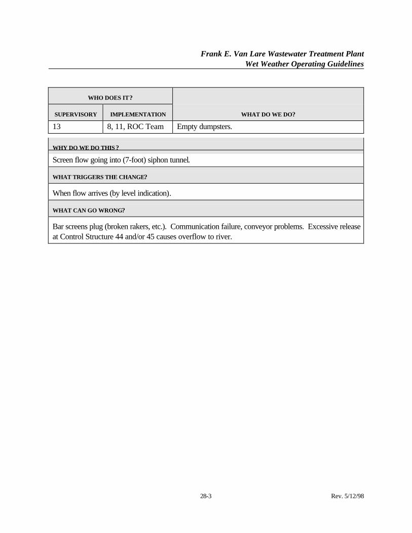
Frank E. Van Lare Wastewater Treatment PlantWet Weather Operating Guidelines
28-3 Rev. 5/12/98
WHO DOES IT?
SUPERVISORY IMPLEMENTATION WHAT DO WE DO?
13 8, 11, ROC Team Empty dumpsters.
WHY DO WE DO THIS ?
Screen flow going into (7-foot) siphon tunnel.
WHAT TRIGGERS THE CHANGE?
When flow arrives (by level indication).
WHAT CAN GO WRONG?
Bar screens plug (broken rakers, etc.). Communication failure, conveyor problems. Excessive releaseat Control Structure 44 and/or 45 causes overflow to river.
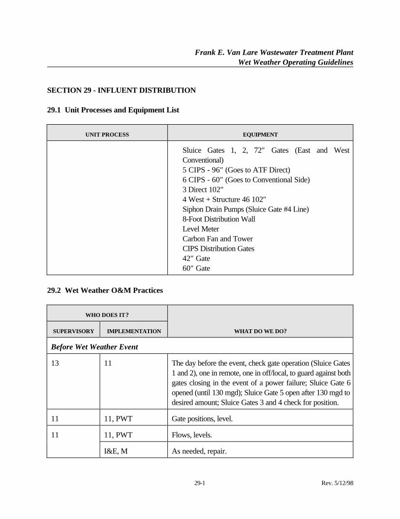
Frank E. Van Lare Wastewater Treatment PlantWet Weather Operating Guidelines
29-1 Rev. 5/12/98
SECTION 29 - INFLUENT DISTRIBUTION
29.1 Unit Processes and Equipment List
UNIT PROCESS EQUIPMENT
⋅ Sluice Gates 1, 2, 72″ Gates (East and WestConventional)
⋅ 5 CIPS - 96″ (Goes to ATF Direct)⋅ 6 CIPS - 60″ (Goes to Conventional Side)⋅ 3 Direct 102″⋅ 4 West + Structure 46 102″⋅ Siphon Drain Pumps (Sluice Gate #4 Line)⋅ 8-Foot Distribution Wall⋅ Level Meter⋅ Carbon Fan and Tower⋅ CIPS Distribution Gates⋅ 42″ Gate⋅ 60″ Gate
29.2 Wet Weather O&M Practices
WHO DOES IT?
SUPERVISORY IMPLEMENTATION WHAT DO WE DO?
Before Wet Weather Event
13 11 The day before the event, check gate operation (Sluice Gates1 and 2), one in remote, one in off/local, to guard against bothgates closing in the event of a power failure; Sluice Gate 6opened (until 130 mgd); Sluice Gate 5 open after 130 mgd todesired amount; Sluice Gates 3 and 4 check for position.
11 11, PWT Gate positions, level.
11, PWT Flows, levels.11
I&E, M As needed, repair.
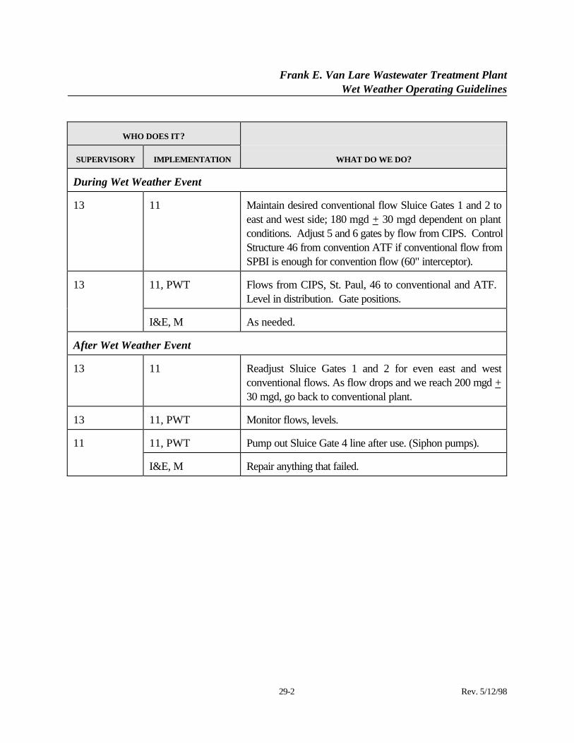
Frank E. Van Lare Wastewater Treatment PlantWet Weather Operating Guidelines
29-2 Rev. 5/12/98
WHO DOES IT?
SUPERVISORY IMPLEMENTATION WHAT DO WE DO?
During Wet Weather Event
13 11 Maintain desired conventional flow Sluice Gates 1 and 2 toeast and west side; 180 mgd + 30 mgd dependent on plantconditions. Adjust 5 and 6 gates by flow from CIPS. ControlStructure 46 from convention ATF if conventional flow fromSPBI is enough for convention flow (60" interceptor).
11, PWT Flows from CIPS, St. Paul, 46 to conventional and ATF. Level in distribution. Gate positions.
13
I&E, M As needed.
After Wet Weather Event
13 11 Readjust Sluice Gates 1 and 2 for even east and westconventional flows. As flow drops and we reach 200 mgd +30 mgd, go back to conventional plant.
13 11, PWT Monitor flows, levels.
11, PWT Pump out Sluice Gate 4 line after use. (Siphon pumps).11
I&E, M Repair anything that failed.
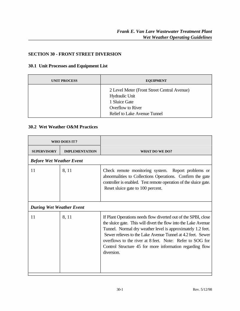
Frank E. Van Lare Wastewater Treatment PlantWet Weather Operating Guidelines
30-1 Rev. 5/12/98
SECTION 30 - FRONT STREET DIVERSION
30.1 Unit Processes and Equipment List
UNIT PROCESS EQUIPMENT
⋅ 2 Level Meter (Front Street Central Avenue)⋅ Hydraulic Unit⋅ 1 Sluice Gate⋅ Overflow to River⋅ Relief to Lake Avenue Tunnel
30.2 Wet Weather O&M Practices
WHO DOES IT?
SUPERVISORY IMPLEMENTATION WHAT DO WE DO?
Before Wet Weather Event
11 8, 11 Check remote monitoring system. Report problems orabnormalities to Collections Operations. Confirm the gatecontroller is enabled. Test remote operation of the sluice gate. Reset sluice gate to 100 percent.
During Wet Weather Event
11 8, 11 If Plant Operations needs flow diverted out of the SPBI, closethe sluice gate. This will divert the flow into the Lake AvenueTunnel. Normal dry weather level is approximately 1.2 feet. Sewer relieves to the Lake Avenue Tunnel at 4.2 feet. Seweroverflows to the river at 8 feet. Note: Refer to SOG forControl Structure 45 for more information regarding flowdiversion.
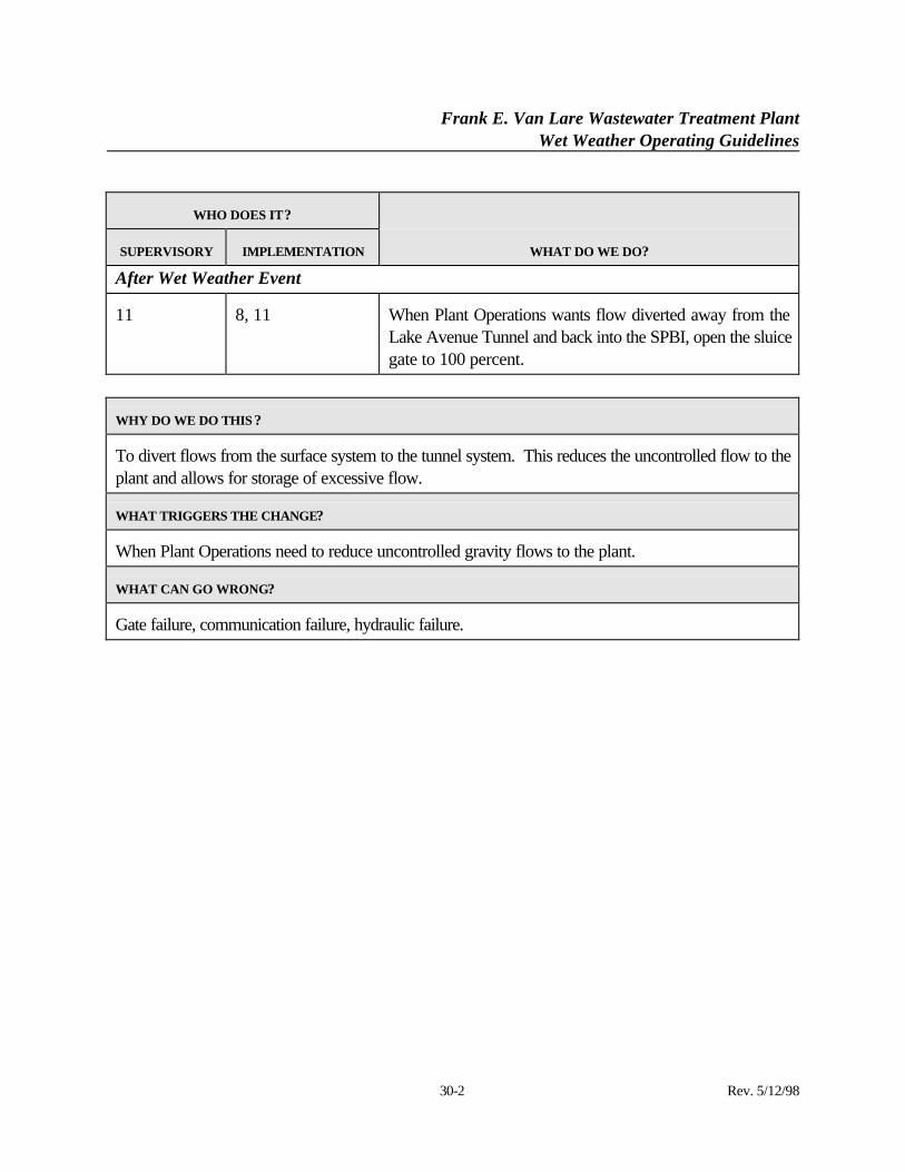
Frank E. Van Lare Wastewater Treatment PlantWet Weather Operating Guidelines
30-2 Rev. 5/12/98
WHO DOES IT?
SUPERVISORY IMPLEMENTATION WHAT DO WE DO?
After Wet Weather Event
11 8, 11 When Plant Operations wants flow diverted away from theLake Avenue Tunnel and back into the SPBI, open the sluicegate to 100 percent.
WHY DO WE DO THIS ?
To divert flows from the surface system to the tunnel system. This reduces the uncontrolled flow to theplant and allows for storage of excessive flow.
WHAT TRIGGERS THE CHANGE?
When Plant Operations need to reduce uncontrolled gravity flows to the plant.
WHAT CAN GO WRONG?
Gate failure, communication failure, hydraulic failure.
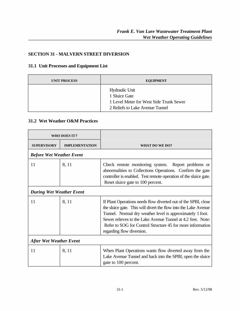
Frank E. Van Lare Wastewater Treatment PlantWet Weather Operating Guidelines
31-1 Rev. 5/12/98
SECTION 31 - MALVERN STREET DIVERSION
31.1 Unit Processes and Equipment List
UNIT PROCESS EQUIPMENT
⋅ Hydraulic Unit⋅ 1 Sluice Gate⋅ 1 Level Meter for West Side Trunk Sewer⋅ 2 Reliefs to Lake Avenue Tunnel
31.2 Wet Weather O&M Practices
WHO DOES IT?
SUPERVISORY IMPLEMENTATION WHAT DO WE DO?
Before Wet Weather Event
11 8, 11 Check remote monitoring system. Report problems orabnormalities to Collections Operations. Confirm the gatecontroller is enabled. Test remote operation of the sluice gate. Reset sluice gate to 100 percent.
During Wet Weather Event
11 8, 11 If Plant Operations needs flow diverted out of the SPBI, closethe sluice gate. This will divert the flow into the Lake AvenueTunnel. Normal dry weather level is approximately 1 foot. Sewer relieves to the Lake Avenue Tunnel at 4.2 feet. Note: Refer to SOG for Control Structure 45 for more informationregarding flow diversion.
After Wet Weather Event
11 8, 11 When Plant Operations wants flow diverted away from theLake Avenue Tunnel and back into the SPBI, open the sluicegate to 100 percent.
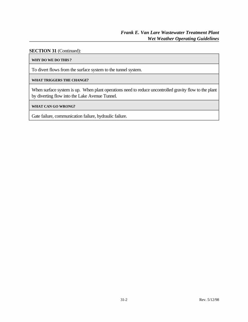
Frank E. Van Lare Wastewater Treatment PlantWet Weather Operating Guidelines
SECTION 31 (Continued):
31-2 Rev. 5/12/98
WHY DO WE DO THIS ?
To divert flows from the surface system to the tunnel system.
WHAT TRIGGERS THE CHANGE?
When surface system is up. When plant operations need to reduce uncontrolled gravity flow to the plantby diverting flow into the Lake Avenue Tunnel.
WHAT CAN GO WRONG?
Gate failure, communication failure, hydraulic failure.
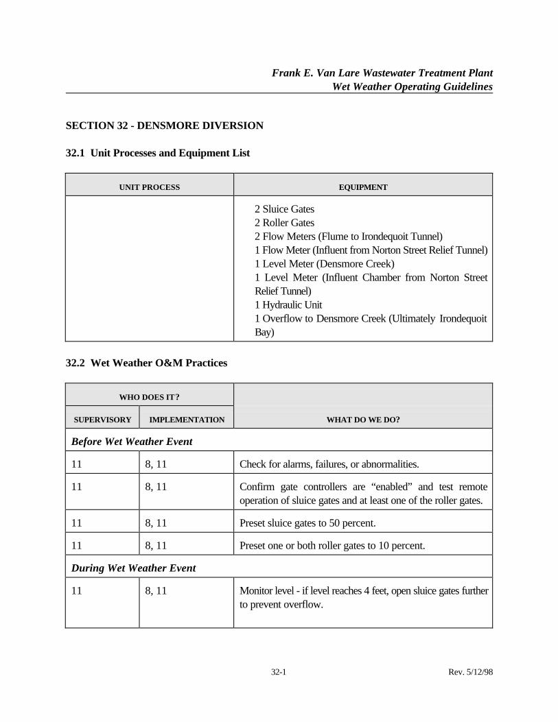
Frank E. Van Lare Wastewater Treatment PlantWet Weather Operating Guidelines
32-1 Rev. 5/12/98
SECTION 32 - DENSMORE DIVERSION
32.1 Unit Processes and Equipment List
UNIT PROCESS EQUIPMENT
⋅ 2 Sluice Gates⋅ 2 Roller Gates⋅ 2 Flow Meters (Flume to Irondequoit Tunnel)⋅ 1 Flow Meter (Influent from Norton Street Relief Tunnel)⋅ 1 Level Meter (Densmore Creek)⋅ 1 Level Meter (Influent Chamber from Norton Street
Relief Tunnel)⋅ 1 Hydraulic Unit⋅ 1 Overflow to Densmore Creek (Ultimately Irondequoit
Bay)
32.2 Wet Weather O&M Practices
WHO DOES IT?
SUPERVISORY IMPLEMENTATION WHAT DO WE DO?
Before Wet Weather Event
11 8, 11 Check for alarms, failures, or abnormalities.
11 8, 11 Confirm gate controllers are “enabled” and test remoteoperation of sluice gates and at least one of the roller gates.
11 8, 11 Preset sluice gates to 50 percent.
11 8, 11 Preset one or both roller gates to 10 percent.
During Wet Weather Event
11 8, 11 Monitor level - if level reaches 4 feet, open sluice gates furtherto prevent overflow.
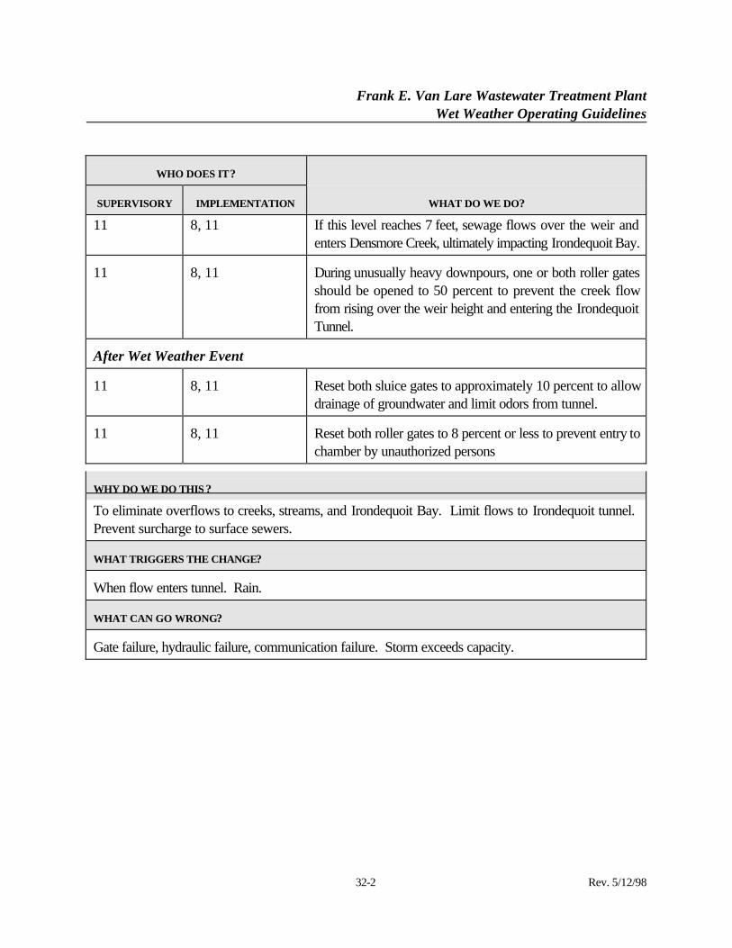
Frank E. Van Lare Wastewater Treatment PlantWet Weather Operating Guidelines
32-2 Rev. 5/12/98
WHO DOES IT?
SUPERVISORY IMPLEMENTATION WHAT DO WE DO?
11 8, 11 If this level reaches 7 feet, sewage flows over the weir andenters Densmore Creek, ultimately impacting Irondequoit Bay.
11 8, 11 During unusually heavy downpours, one or both roller gatesshould be opened to 50 percent to prevent the creek flowfrom rising over the weir height and entering the IrondequoitTunnel.
After Wet Weather Event
11 8, 11 Reset both sluice gates to approximately 10 percent to allowdrainage of groundwater and limit odors from tunnel.
11 8, 11 Reset both roller gates to 8 percent or less to prevent entry tochamber by unauthorized persons
WHY DO WE DO THIS ?
To eliminate overflows to creeks, streams, and Irondequoit Bay. Limit flows to Irondequoit tunnel. Prevent surcharge to surface sewers.
WHAT TRIGGERS THE CHANGE?
When flow enters tunnel. Rain.
WHAT CAN GO WRONG?
Gate failure, hydraulic failure, communication failure. Storm exceeds capacity.
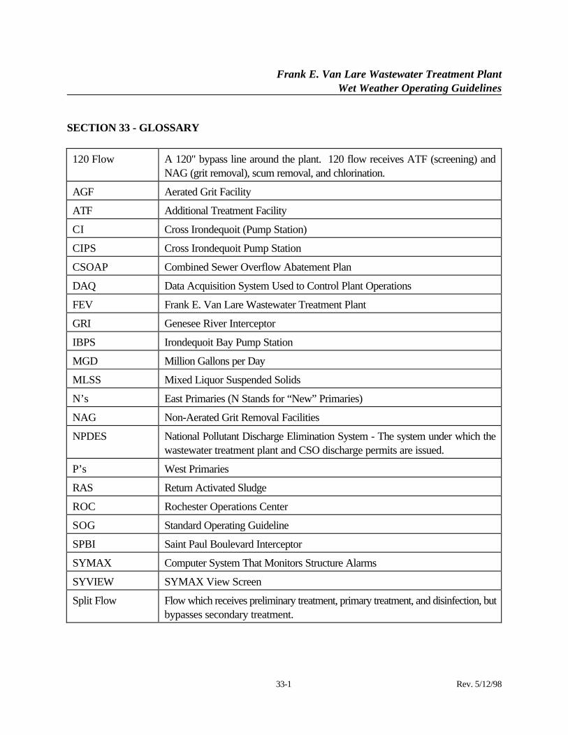
Frank E. Van Lare Wastewater Treatment PlantWet Weather Operating Guidelines
33-1 Rev. 5/12/98
SECTION 33 - GLOSSARY
120 Flow A 120" bypass line around the plant. 120 flow receives ATF (screening) andNAG (grit removal), scum removal, and chlorination.
AGF Aerated Grit Facility
ATF Additional Treatment Facility
CI Cross Irondequoit (Pump Station)
CIPS Cross Irondequoit Pump Station
CSOAP Combined Sewer Overflow Abatement Plan
DAQ Data Acquisition System Used to Control Plant Operations
FEV Frank E. Van Lare Wastewater Treatment Plant
GRI Genesee River Interceptor
IBPS Irondequoit Bay Pump Station
MGD Million Gallons per Day
MLSS Mixed Liquor Suspended Solids
N’s East Primaries (N Stands for “New” Primaries)
NAG Non-Aerated Grit Removal Facilities
NPDES National Pollutant Discharge Elimination System - The system under which thewastewater treatment plant and CSO discharge permits are issued.
P’s West Primaries
RAS Return Activated Sludge
ROC Rochester Operations Center
SOG Standard Operating Guideline
SPBI Saint Paul Boulevard Interceptor
SYMAX Computer System That Monitors Structure Alarms
SYVIEW SYMAX View Screen
Split Flow Flow which receives preliminary treatment, primary treatment, and disinfection, butbypasses secondary treatment.
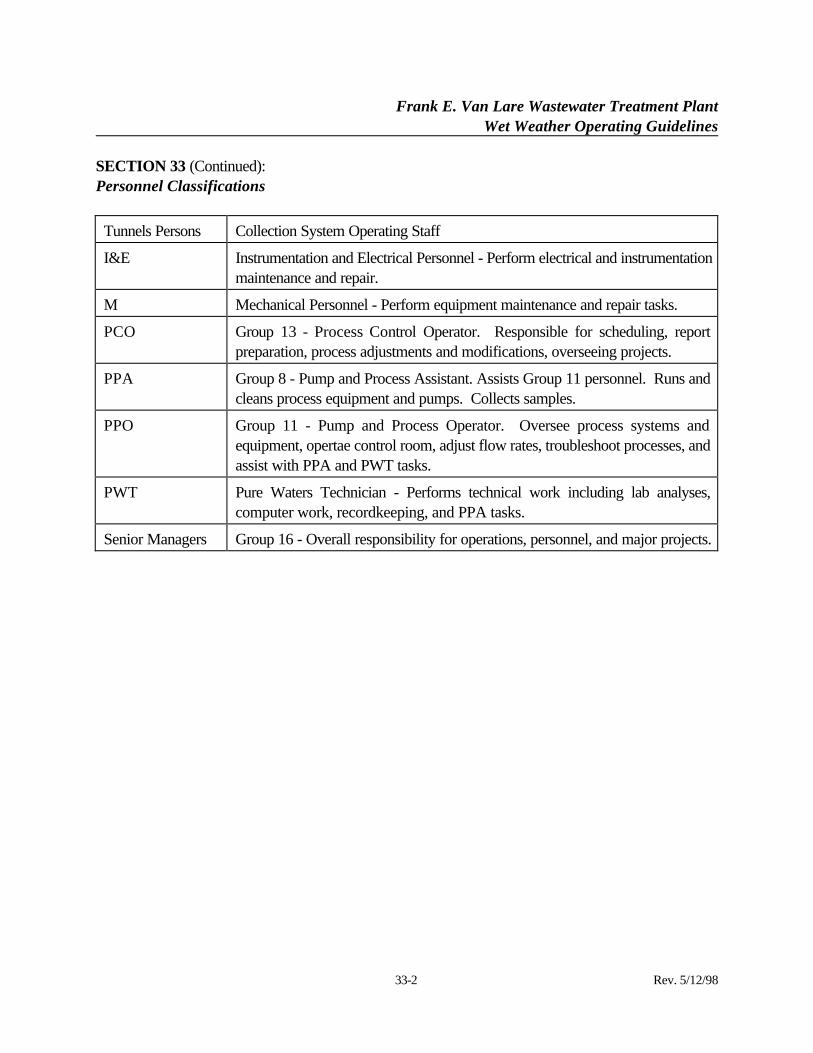
Frank E. Van Lare Wastewater Treatment PlantWet Weather Operating Guidelines
SECTION 33 (Continued):
33-2 Rev. 5/12/98
Personnel Classifications
Tunnels Persons Collection System Operating Staff
I&E Instrumentation and Electrical Personnel - Perform electrical and instrumentationmaintenance and repair.
M Mechanical Personnel - Perform equipment maintenance and repair tasks.
PCO Group 13 - Process Control Operator. Responsible for scheduling, reportpreparation, process adjustments and modifications, overseeing projects.
PPA Group 8 - Pump and Process Assistant. Assists Group 11 personnel. Runs andcleans process equipment and pumps. Collects samples.
PPO Group 11 - Pump and Process Operator. Oversee process systems andequipment, opertae control room, adjust flow rates, troubleshoot processes, andassist with PPA and PWT tasks.
PWT Pure Waters Technician - Performs technical work including lab analyses,computer work, recordkeeping, and PPA tasks.
Senior Managers Group 16 - Overall responsibility for operations, personnel, and major projects.