Embed Size (px)
Citation preview

Westpower Asset Management Plan 2004
Page - 1
Executive Summary
The Asset Management Plan is a foundation document, which summarises the work undertaken on all ofWestpower’s assets.
Each year, a comprehensive update of the plan is completed including network changes that have takenplace. Furthermore, the results of a formal, external peer review process are taken into account to ensurethat this plan meets current disclosure requirements, in terms of the Electricity (Information Disclosure)Regulations 1999 and is continually improved in both content and layout.
Period CoveredThis particular plan was completed in March 2004 and covers a planning period from 1 April 2004 through to31 March 2014. The main focus is placed on the next three years, with updates being completed annually.
The summary is prepared for people who may not be involved within the business of electricity distributionnetworks and associated services, but who understand and have an interest in efficient management.
Objective of the Plan
The defined objective of the Asset Management Plan is:
“To provide a systematic approach to the planning of programmes which are intended toensure that the condition and performance of infrastructure assets are being efficientlymaintained or improved to satisfy stakeholders requirements.”
Westpower has developed a mature approach to asset management that will protectthe value of the infrastructure assets for stakeholders. In the continual pursuit of
excellence, every effort will be made to improve the high standard already achievedand provide management of Westpower assets.

Westpower Asset Management Plan 2004
Page - 2
Asset Management Systems and Information
Technology
The basic technology involved in the transmission and distribution of electrical energy has changed little overthe last fifty years. Nevertheless, small incremental changes continue to be made in the materials employedleading to improved performance and higher efficiency, and Westpower will continue to monitor these andapply the technologies where appropriate.
The major impact of technology on Westpower’s activities will be in the areas of Information Technology,SCADA (Supervisory Control and Data Acquisition) operation of remote pieces of plant, and the potentialimpact of distributed generation. By means of an ongoing Distribution Automation (DA) programme usingthese technologies, Westpower intends to continually improve the reliability of its network by reducing faultrestoration times. This allows remote switches to be immediately operated from the control room over radiolinks that previously could have taken up to an hour for fault staff to reach, leading to greatly reduced poweroutage times.
A recently implemented GIS (Geographic Information System) has allowed Westpower to analyse the condi-tion of the network and make informed decisions crucial to achieving optimal Asset Management levels. Inaddition, the GIS has also allowed Westpower to view lightning strikes within the network area. This helps tospeed up the recovery of lightning related faults and identify lightning prone areas.
A tree structured job costing system ensures any costs incurred on the network are reportable to feeder level.This system divides network expenditure into appropriate activities (Inspection-Service and Testing, Faults,Repairs, Replacements, Enhancements and Development), Asset Type and Location. Detailed reports in-cluding capital and operating expenditure may be generated at any time.
A computerised Service Maintenance Management maintenance tracking system has been developed tomaintain a complete history of each asset and to ensure that regular scheduled maintenance is carried outwhen needed.
When maintenance is required, live line maintenance techniques will be used wherever possible to reducethe number and duration of power outages. Westpower’s line contractor is trained in live line Glove andBarrier techniques and has all of the specialist equipment needed to provide a level of repair service equal toany in the country. Most maintenance tasks involving voltages from 400V to 33,000V can now be carried outwithout taking the power off.
New technology will continue to be employed where Westpower group engineers are satisfied that it will bereliable and it is shown to improve service quality and performance.
Information
Adequate and accurate information is a fundamental need in order to manage assets efficiently. Historicinformation about the assets currently in place has some gaps. Previous records were inconsistent andlacked detail of equipment types.
Westpower now has practices established for all contractors in the field who carry out work on the networksto improve this information.
Accurate records are also being obtained for all new work and replacement projects carried out on thenetwork.

Westpower Asset Management Plan 2004
Page - 3
Asset Management Practices
Westpower is constantly striving to find more efficient ways to carry out its daily functions, by reducing costsand improving productivity.
The benchmark of best commercial practice is constantly moving, particularly with the introduction of regula-tory control by the government, which looks at factors such as price and supply reliability. Therefore, Westpowermust be dynamic and innovative, and this culture starts with the Board of Directors, which includes significantcommercial and financial experience.
The condition of all equipment is regularly assessed and equipment technical and condition data is stored ina sophisticated database. The GIS system is used to present this data geographically.
Best practice maintenance techniques are employed wherever possible, and the company regularly ex-changes information with other utilities. Furthermore, the technical awareness of staff is maintained throughregular staff training programmes
Westpower encourages suppliers to continuously improve their services and techniques, and at the sametime negotiates competitive supply and maintenance contracts. A fully commercial relationship exists be-tween Westpower and its contracting subsidiary ElectroNet Services, which encourages price efficiency andhigh productivity through commercial discipline.
Network and Asset Description
Westpower’s distribution lines comprise 1970 circuit kilometres of high voltage AC distribution lines of vary-ing line capacities, which are dependent upon local demands and geographical considerations. Operatingvoltages include 66 kilovolt (kV), 33 kV, and 11 kV. These lines involve a large population of power poles ofvarying types.
The Asset Management Plan covers the electrical and associated systems owned by Westpower.
Service Level Objectives
While ultimately it is customers’ requirements and financial commitments that drive work that might altersystem reliability, the asset management plan is based upon maintaining the target of 110 system-minuteslost per year for 2004/05. It is intended to maintain a constant level of service from this date on. Customerscommitting to commercial agreements may be provided with supply reliability either greater or lesser thanthat projected for the network as a whole.
SAIDI - System Average Interruption Dura-tion IndexThis gives the average total time in minutesper year that each customer is without supply.A SAIDI of say 100 minutes means that everycustomer on a particular network experiencesan average total time without electricity of 100minutes per year.
SAIDI
0
50
100
150
200
250
1999-00 2000-01 2001-02 2002-03 2003-04 2004-05 2005-06 2006-07
SAIDI

Westpower Asset Management Plan 2004
Page - 4
Lifecycle Asset Management and Development Plan
Regular site checks of all Zone Substations take place on a monthly basis. For large distribution substationsthis is extended to three months, while for a small rural distribution substation this is further extended to fiveyears.
Large transformers are subjected to extensive testing because of their critical role in network reliability. Thisincludes Dissolved Gas Analysis (DGA) which monitors the internal transformer condition based on gasesdissolved in the transformer oil.
For distribution transformers, regular demand checks, visual inspections and basic oil tests provide thenecessary baseline condition data. For some of the older painted transformers, refurbishment or replace-ment is required rather than general maintenance.
Risk Assessment
Risk Management practices have been embraced as a means of ensuring that all commercial risks are takeninto account and appropriate strategies are in place to manage these risks. In this way the long-term viabilityof Westpower is protected.
A full Risk Management Plan (RMP) has been completed after an in-depth look at Westpower’s operationsand environment in conjunction with risk management consultants.
SAIFI - System Average Interruption Fre-quency IndexThis gives the average number of interruptionsevery customer experiences in a year. A SAIFIof 2.5 means that, on average, every customerexperiences 2.5 interruptions in the year.
CAIDI - Customer Average InterruptionDuration IndexThis gives the average duration of aninterruption. In other words a CAIDI of 60minutes means that if a customerexperiences an interruption, the averageduration of that interruption is 60 minutes.It is a measure of how long a powercompany takes to locate and repair a“typical” fault.
SAIFI
CAIDI
SAIFI
0
0.5
1
1.5
2
2.5
3
1999-00 2000-01 2001-02 2002-03 2003-04 2004-05 2005-06 2006-07
CAIDI
0
20
40
60
80
100
120
1999-00 2000-01 2001-02 2002-03 2003-04 2004-05 2005-06 2006-07
Westpower Asset Management Plan 2004
Page - 5
Westpower network assets can be at risk from:
• Natural disasters – earthquakes, flood, slippage, climatic conditions etc.• People related – excavations, vandalism, poor workmanship etc.• Non-supply – non-supply by Transpower, Generators.• Asset failure – capacity, reliability, structural, cost.
At all stages through the Asset Management planning process, Westpower’s staff strive to reduce the impactof such risks.
Performance and Plans for Improvement
Westpower’s Asset Management approach is based on evaluating the following key areas of life cycle assetmanagement:
• Processes and Practices • Commercial Tactics;• Data and Knowledge • Organisational / People issues• Information Support Systems • Asset Management Plans
Westpower has a goal of meeting and exceeding industry best practice through a process of continualimprovement. This is achieved by means of ongoing reviews based on a gap analysis, which categorisesareas and individual processes that need attention.
As each area is dealt with as a team exercise throughout the year, the gap analysis is updated to showcurrent performance levels.
MAJOR PROJECTS
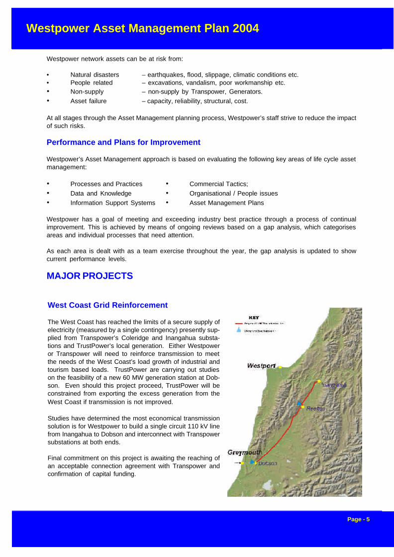
West Coast Grid Reinforcement
The West Coast has reached the limits of a secure supply ofelectricity (measured by a single contingency) presently sup-plied from Transpower’s Coleridge and Inangahua substa-tions and TrustPower’s local generation. Either Westpoweror Transpower will need to reinforce transmission to meetthe needs of the West Coast’s load growth of industrial andtourism based loads. TrustPower are carrying out studieson the feasibility of a new 60 MW generation station at Dob-son. Even should this project proceed, TrustPower will beconstrained from exporting the excess generation from theWest Coast if transmission is not improved.
Studies have determined the most economical transmissionsolution is for Westpower to build a single circuit 110 kV linefrom Inangahua to Dobson and interconnect with Transpowersubstations at both ends.
Final commitment on this project is awaiting the reaching ofan acceptable connection agreement with Transpower andconfirmation of capital funding.
Westpower Asset Management Plan 2004
Page - 6
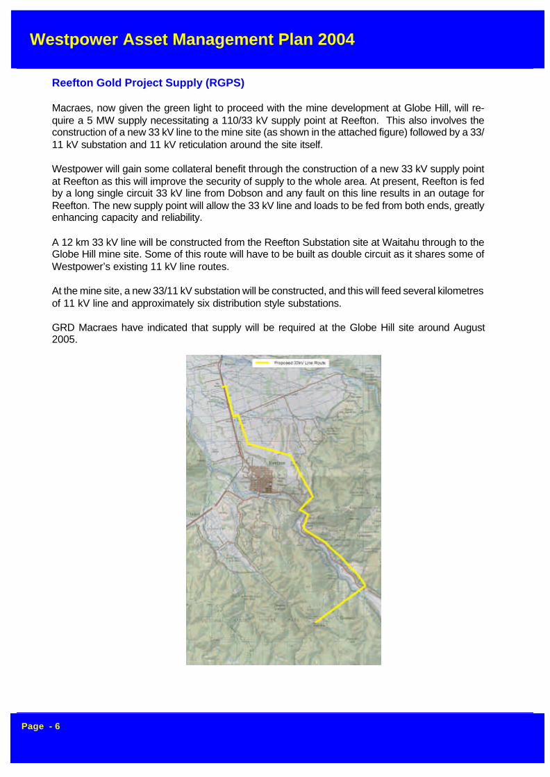
Reefton Gold Project Supply (RGPS)
Macraes, now given the green light to proceed with the mine development at Globe Hill, will re-quire a 5 MW supply necessitating a 110/33 kV supply point at Reefton. This also involves theconstruction of a new 33 kV line to the mine site (as shown in the attached figure) followed by a 33/11 kV substation and 11 kV reticulation around the site itself.
Westpower will gain some collateral benefit through the construction of a new 33 kV supply pointat Reefton as this will improve the security of supply to the whole area. At present, Reefton is fedby a long single circuit 33 kV line from Dobson and any fault on this line results in an outage forReefton. The new supply point will allow the 33 kV line and loads to be fed from both ends, greatlyenhancing capacity and reliability.
A 12 km 33 kV line will be constructed from the Reefton Substation site at Waitahu through to theGlobe Hill mine site. Some of this route will have to be built as double circuit as it shares some ofWestpower’s existing 11 kV line routes.
At the mine site, a new 33/11 kV substation will be constructed, and this will feed several kilometresof 11 kV line and approximately six distribution style substations.
GRD Macraes have indicated that supply will be required at the Globe Hill site around August2005.
Westpower Asset Management Plan 2004
Page - 7
FINANCIAL SUMMARY
Financial Forecasts
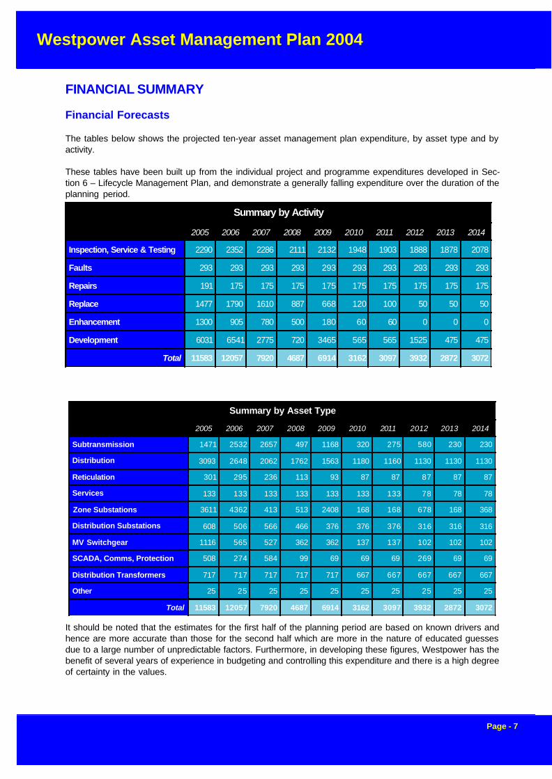
The tables below shows the projected ten-year asset management plan expenditure, by asset type and byactivity.
These tables have been built up from the individual project and programme expenditures developed in Sec-tion 6 – Lifecycle Management Plan, and demonstrate a generally falling expenditure over the duration of theplanning period.
It should be noted that the estimates for the first half of the planning period are based on known drivers andhence are more accurate than those for the second half which are more in the nature of educated guessesdue to a large number of unpredictable factors. Furthermore, in developing these figures, Westpower has thebenefit of several years of experience in budgeting and controlling this expenditure and there is a high degreeof certainty in the values.
Summary by Activity
2005 2006 2007 2008 2009 2010 2011 2012 2013 2014
Inspection, Service & Testing 2290 2352 2286 2111 2132 1948 1903 1888 1878 2078
Faults 293 293 293 293 293 293 293 293 293 293
Repairs 191 175 175 175 175 175 175 175 175 175
Replace 1477 1790 1610 887 668 120 100 50 50 50
Enhancement 1300 905 780 500 180 60 60 0 0 0
Development 6031 6541 2775 720 3465 565 565 1525 475 475
Total 11583 12057 7920 4687 6914 3162 3097 3932 2872 3072
Summary by Asset Type
2005 2006 2007 2008 2009 2010 2011 2012 2013 2014
Subtransmission 1471 2532 2657 497 1168 320 275 580 230 230
Distribution 3093 2648 2062 1762 1563 1180 1160 1130 1130 1130
Reticulation 301 295 236 113 93 87 87 87 87 87
Services 133 133 133 133 133 133 133 78 78 78
Zone Substations 3611 4362 413 513 2408 168 168 678 168 368
Distribution Substations 608 506 566 466 376 376 376 316 316 316
MV Switchgear 1116 565 527 362 362 137 137 102 102 102
SCADA, Comms, Protection 508 274 584 99 69 69 69 269 69 69
Distribution Transformers 717 717 717 717 717 667 667 667 667 667
Other 25 25 25 25 25 25 25 25 25 25
Total 11583 12057 7920 4687 6914 3162 3097 3932 2872 3072

Westpower Asset Management Plan 2004
Page - 8
Figure A below shows the distribution of expenditure in terms of work activity. As expected, the level ofexpenditure for Development is significantly greater than for other activities, due to major projects such asthe West Coast Grid Reinforcement Project .
Previously Westpower has had a large proportion of older lines that were rapidly approaching failure, and areplacement programme ofthe last five years has sub-stantially overcome this prob-lem. The I,S&T expenditurehas been increased whencompared to the previous yearto provide enhanced monitor-ing of the condition of oldercomponents such as smalltransformers that have devel-oped a gasket problem. Bydoing this, future mainte-nance may be targeted towardlife extension of ageing as-sets.
The enhancement expendi-ture also reflects a continuedemphasis on distribution au-tomation as reclosers anddisconnectors are progres-sively automated. By doingthis, Westpower is able togreatly reduce outage dura-tions and switching times, re-sulting in an improved SAIDIreliability statistic.
The expenditure by assettype is depicted in figure B.As would be expected, thebulk of the expenditure in-volves subtransmission andzone substation assets re-lated to the major projectsdiscussed above.
Assumptions and Sensitivity Analysis
Some basic assumptions have been made. These include:• As a Lines Business, Westpower will continue to be a going concern under the new regulatory
regime.• Asset Management, System Control and Corporate Services functions will be provided by ElectroNet
Services and be based in Greymouth.• The Lines Business will continue to own ElectroNet Services and to operate it on an arms length
basis
Figure B Expenditure by Asset Type
Expenditure by Asset Type
13%
1%31%
5%
10%4% 6% 0%
3%27%
Subtransmission Lines
Distribution Lines
Reticulation Lines
Services
Zone Substations
Distribution Substations
MV Switchgear
Scada, Comms, Protection
Distribution Transformers
Other
Figure A Expenditure by Activity
Expenditure by Activity
20%
3%2%
13%
11%
51%
I,S & T
Faults
Repairs
Replacement
Enhancement
Development

Westpower Asset Management Plan 2004
Page - 9
Contents
Executive Summary ..........................................................................................................................1Period Covered .........................................................................................................................1Objective of the Plan .................................................................................................................1
Asset Management Systems and Information ..................................................................................2Technology ...............................................................................................................................2Information ...............................................................................................................................2Asset Management Practices ....................................................................................................3Network and Asset Description ..................................................................................................3Service Level Objectives ...........................................................................................................3Lifecycle Asset Management and Development Plan ...................................................................4
Risk Assessment ..............................................................................................................................4Performance and Plans for Improvement ....................................................................................5
MAJOR PROJECTS ..........................................................................................................................5West Coast Grid Reinforcement .................................................................................................5Reefton Gold Project Supply (RGPS) .........................................................................................6
FINANCIAL SUMMARY .....................................................................................................................7Financial Forecasts ...................................................................................................................7................................................................................................................................................8Assumptions and Sensitivity Analysis .........................................................................................8
FOREWORD ...................................................................................................................................15Overview of Westpower Organisation .......................................................................................16
1.0 INTRODUCTION ........................................................................................................................171.1 Westpower Yesterday .......................................................................................................171.2 Westpower Today .............................................................................................................171.3 Westpower Tomorrow .......................................................................................................181.4 Issues Facing Westpower .................................................................................................181.5 Objective and Stakeholders ...............................................................................................18
1.5.1 Objective of the Plan 181.5.2 Stakeholders in the Plan 18
1.6 Scope of Asset Management Plan .....................................................................................191.6.1 Working Assumptions of the Asset Management Plan 19
1.7 Corporate Asset Management Drivers ................................................................................201.7.1 Safety 201.7.2 Customer Service 201.7.3 Economic Efficiency 221.7.4 Environmental Responsibility 221.7.5 Corporate Profile 221.7.6 Legislation and Compliance 22
1.8 Asset Management Linkage with Westpower Performance ..................................................231.9 Plan Structure and Approach .............................................................................................23
2.0 LEVELS OF SERVICE ...............................................................................................................242.1 Introduction .......................................................................................................................242.2 Customer Research and Expectations ...............................................................................24
252.2.1 Impact of the Proposed New Regulatory Regime 25
Westpower Asset Management Plan 2004
Page - 10
2.3 Statutory Requirements .....................................................................................................252.4 Strategic and Corporate Goals ...........................................................................................262.5 Target Levels of Service ....................................................................................................27
3.0 PLANNING FRAMEWORK ........................................................................................................293.1 Load Forecasting ..............................................................................................................29
3.1.1 Introduction 293.1.2 Historical Drivers 303.1.3 Future Load Projections 313.1.4 Options for Handling Load Increases 33
3.2 Design Policy and Planning Guidelines 343.2.1 Security Guidelines 343.2.2 Voltage Policy 353.2.3 Voltage Control 353.2.4 Protection Policy 36
3.3 Strategic Plans by Area .....................................................................................................373.3.1 Reefton Network 373.3.2 Greymouth Network 373.3.3 Hokitika Network 383.3.4 South Westland Network 38
4.0 ASSET DESCRIPTION ..............................................................................................................394.1 Sub-transmission Assets ....................................................................................................40
4.1.1 Asset Justification 404.1.2 66 kV Lines 404.1.3 33 kV Lines and Cables 41
4.2 Distribution Assets ............................................................................................................454.2.1 Asset Justification 454.2.2 11 kV Overhead Lines 454.2.3 11 kV Distribution Line Components 464.2.4 11 kV Cables 47
4.3 Reticulation Assets ...........................................................................................................474.3.1 Asset Justification 474.3.2 Overhead 400 V Lines 474.3.3 Underground 400 V Cables 47
4.4 Services ...........................................................................................................................484.4.1 Asset Justification 48
4.5 Zone Substations ..............................................................................................................484.5.1 Asset Justification 504.5.2 Power Transformers 504.5.3 Switchgear 504.5.4 Oil Containment 50
4.6 Distribution Substations .....................................................................................................514.6.1 Asset Justification 53
4.7 Medium Voltage Switchgear ..............................................................................................534.7.1 Asset Justification 53
4.8 SCADA, Communications and Protection ...........................................................................544.8.1 Asset Justification 544.8.2 Supervisory Control And Data Acquisition System (SCADA) 544.8.3 Remote Terminal Units (RTUs) 554.8.4 Communication System 554.8.5 Power Line Carrier (PLC) 564.8.6 Communication Cables 564.8.7 VHF Network 564.8.8 UHF Network 564.8.9 Protection 57
4.9 Distribution Transformers ..................................................................................................574.9.1 Asset Justification 58
58

Westpower Asset Management Plan 2004
Page - 11
4.10 Ripple Injection Plants ......................................................................................................584.10.1 Asset Justification
5.0 Asset Condition .......................................................................................................................605.1 Sub-Transmission Asset Condition .....................................................................................60
5.1.1 Current Overhead Line Asset Condition Overview 615.1.2 Condition of Specific Line Components 625.1.3 Condition of Access Roads 635.2.0 Distribution Line Condition 645.2.1 Current Overhead Line Asset Condition Overview 645.2.2 Condition of Specific Line Components 65
5.3 Low Voltage Reticulation Lines ..........................................................................................665.3.1 Current Asset Condition 665.3.2 Condition of Specific LV Line Components 67
5.4.0 Service Lines .................................................................................................................675.5.0 Zone Substations ...........................................................................................................68
5.5.1 General Condition 685.5.2 Transformers 685.5.3 Switchgear 685.5.4 Minimum Oil Switchgear 685.5.5 Outdoor Reclosers 695.5.6 Indoor Switchgear 695.5.7 Disconnectors 705.5.8 Buswork 705.5.9 Instrument Transformers 705.5.10 Oil Containment 705.5.11 Earthing Systems 715.5.12 SCADA Remote Terminal Units 715.5.13 Protection Relays 715.5.14 Other Station Equipment 71
5.6.0 Distribution Substations ..................................................................................................715.6.1 Dominion Drop Out (DDO) Fuses 725.6.2 Earthing Systems 72
5.7 Medium Voltage Switchgear ..............................................................................................725.7.1 Regulators 725.7.2 Circuit Breakers 735.7.3 Pole Mounted Reclosers 735.7.4 Disconnectors 73
5.8 SCADA, Communications and Protection ...........................................................................735.8.1 Supervisory Control and Data Acquisition (SCADA) 735.8.2 Communication System 73
5.9 Distribution Transformers ..................................................................................................745.10 Ripple Control ................................................................................................................74
5.10.1 Ripple Injection Plants 74
6.0 LIFECYCLE MANAGEMENT PLAN ...........................................................................................756.1 Overview .........................................................................................................................75
6.1.1 Maintenance 756.1.2 Replacements 766.1.4 Development 776.1.3 Enhancement 77
6.2 Sub-Transmission Assets ..................................................................................................796.2.1 Greymouth-Kumara 66 kV Line 796.2.2 Kumara-Kawhaka 66 kV Line 816.2.3 North Westland 33 kV Network 81
Projected Sub-Transmission Expenditure .................................................................................826.2.4 South Westland 33 kV Network 846.2.45 Other 33 kV Network Projects 86
6.3 Distribution Assets ............................................................................................................86

Westpower Asset Management Plan 2004
Page - 12
6.3.1 Reefton Area 876.3.2 Greymouth Area 906.3.3 Hokitika Area 966.3.4 South Westland Area 97
6.4.0 Reticulation Assets .........................................................................................................996.4.1 Reefton Area 996.4.2 Greymouth Area 1016.4.3 Hokitika Area 1026.4.4 South Westland 103
6.5.0 Services ...................................................................................................................... 1046.5.1 Service Poles 104
6.6 Zone Substations ............................................................................................................ 1056.6.3 Planned Repairs and Refurbishment ................................................................................... 1086.6.4 Replacement Programmes .................................................................................................. 1086.6.5 Maintenance Summary ........................................................................................................ 1106.6.6 Enhancement ...................................................................................................................... 1106.6.7 Development ....................................................................................................................... 111
6.7.0 Distribution Substations ................................................................................................ 1156.7.1 Inspection, Servicing and Testing 1156.7.2 Fault Repairs 1156.7.3 Planned Repairs and Refurbishment 1156.7.4 Replacement Programmes 1166.7.5 Enhancement 1176.7.6 Development 118
6.8 MV Switchgear ............................................................................................................... 1186.8.1 Inspection, Servicing and Testing 1186.8.2 Fault Repairs 1196.8.3 Planned Repairs and Refurbishment 1196.8.4 Replacement Programmes 1196.8.5 Enhancements 1216.8.6 Development 122
6.9 SCADA, Comms and Protection ...................................................................................... 1246.9.1 Periodic Inspections, Servicing and Testing 1246.9.2 Planned Repairs and Refurbishment 1256.9.3 Replacement Programmes 1256.9.4 Maintenance Summary 1266.9.5 Enhancement 1266.9.6 Development 127
6.10 Distribution Transformers .............................................................................................. 1286.10.1 Maintenance 1286.10.2 Enhancement 1316.10.3 Development 131
6.11 Other ........................................................................................................................... 1316.11.1 Maintenance 1326.11.2 Enhancement 1326.11.3 Development 132
7.0 FINANCIAL SUMMARY ........................................................................................................... 1337.1 Financial Forecasts ......................................................................................................... 1337.2 Assumptions and Sensitivity Analysis ............................................................................... 1357.3 Actual Deviations from Previous Asset Management Plans ............................................... 136
8.0 ASSET MANAGEMENT PRACTICES ....................................................................................... 1378.1 Introduction .................................................................................................................... 1378.2 Rationalisation of Responsibilities and Procedures ............................................................ 1408.3 Network Services Operational Support ............................................................................. 1408.4 Information Systems Development ................................................................................... 1408.5 Specifications, Procedures and Manuals .......................................................................... 1408.6 Deregulation/Compliance with MoC Requirements ............................................................ 1408.7 Electricity Industry Reform Act ......................................................................................... 140

Westpower Asset Management Plan 2004
Page - 13
8.7.1 Economies of Scale 1418.8 Commerce Commission Requirements ............................................................................ 1418.9 Regulatory Risk .............................................................................................................. 142
8.9.1 Pricing Regulation 142 Countervailing Power 142
8.10 Asset Renewal Policy .................................................................................................... 1428.11 CAPEX Analysis ........................................................................................................... 143
9.0 NETWORK RELIABILITY ........................................................................................................ 1448.11 Distributed Generation ................................................................................................... 1449.1 Westpower Sub-transmission and Distribution Networks ................................................... 145
9.1.1 Cables 1459.1.2 Aerial Bundled Cable 1469.1.3 Overhead Lines 146
9.2 ZONE SUBSTATIONS .................................................................................................... 1469.3 TRANSPOWER NETWORK ............................................................................................ 1479.4 Overall Reliability ............................................................................................................ 147
10 RISK MANAGEMENT PLAN ..................................................................................................... 15010.1Risk Management Planning Framework ........................................................................... 15010.2Risk Planning Methodology ............................................................................................. 151
Stage 1. Assess Potential Risk Consequence 152Stage 2. Identify Responsibility 152Stage 4. Identify Current Controls 153Stage 5. Assess Control Effectiveness 153Stage 3. Identify High Consequence Risks 153Stage 6. Review Control Weakness and Loss History 154Stage 7. Assess Likelihood of Occurrence 154Stage 8. Calculate Exposure and Residual Risk 155Stage 9. Prioritise Risks 155Stage 10. Action Plan Development 155
10.3 Failure Mode and Effects Critically Analysis .................................................................... 15510.4 Safety .......................................................................................................................... 15710.5 Environmental .............................................................................................................. 15710.6 Key Risks Identified ...................................................................................................... 15710.7 Mitigation Measures ...................................................................................................... 159
11 IMPROVEMENT PLAN ............................................................................................................. 16011.1 Asset Management Planning Framework ........................................................................ 160
11.1.1 Processes 16111.2 Knowledge of Asset 16111.3 Asset Accounting and Costing 16211.4 Strategic Planning Life Cycle 16311.5 Asset Creation / Disposal 16411.6 Asset Operations 16511.7 Asset Maintenance 16511.8 Job / Work Resource Management 16611.9 Review Audit (Continuous improvement) 16711.10 Data and Knowledge (Data Availability / Quality) 16711.11 Asset Information (Support) Systems 16911.12 Primary Applications 16911.13 Secondary Applications 17011.14 Life Cycle Applications 17011.15 General Overall System Issues 17111.16 Commercial Tactics (Contestability/Contracted Services) 17111.17 Organisational/People Issues 17211.18 Asset Management Plans 173
Westpower Limited: Gap Analysis ......................................................................................... 175Westpower Limited: Gap Analysis ......................................................................................... 176

Westpower Asset Management Plan 2004
Page - 14
Westpower Limited: Gap Analysis ......................................................................................... 177Westpower Limited: Gap Analysis ......................................................................................... 178
APPENDIX A ................................................................................................................................. 179Maintenance Activity Definitions ............................................................................................. 179Inspection, Service and Testing .............................................................................................. 179Enhancement and Development Activity Definitions ................................................................. 179Other Activity Definitions ........................................................................................................ 180Asset Type Definitions ........................................................................................................... 180

Westpower Asset Management Plan 2004
Page - 15
FOREWORD
This is the eleventh Asset Management Plan to be produced for Westpower and includes only minor changesfrom last year.
The Plan defines the service objectives and gives focus on life cycle management by presenting operations,maintenance and renewal policies, needs and programmes by asset type. The following Asset Managementplanning process has been suggested in order to effectively integrate best practice features. These establishthe service standards and future demands to meet business, legislative and other needs, while developingoptimum lifecycle Asset Management strategies, and cash flow projections based on assessing non assetsolutions, failure modes, cost/benefits and risk.
Figure 1 : Asset Management Plan Process
DATA COLLECTION /MEASURE PERFORMANCE
LEVEL OFSERVICE
ASSET MANAGEMENTPLAN
ASSESS FINANCIALIMPACTS (Cash flow)
PREDICT DEMAND
RISK ASSESSMENT /PRIORITISATION
PREDICT MODESOF FAILURE
TREATMENT OPTIONSAVAILABLE
DETERMINE AND EVALUATECOSTS & BENEFITS
• Environmental• Strategic• Legislative
• Customer• Financial• Political
(Advanced Asset Management Improvement Area)
EXISTING DATA
Figure 1: Asset Management Plan Process
Westpower Asset Management Plan 2004
Page - 16
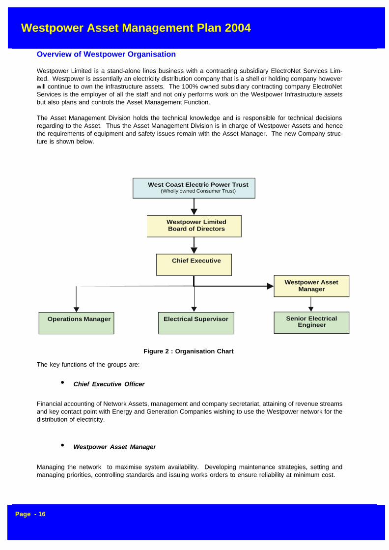
Overview of Westpower Organisation
Westpower Limited is a stand-alone lines business with a contracting subsidiary ElectroNet Services Lim-ited. Westpower is essentially an electricity distribution company that is a shell or holding company howeverwill continue to own the infrastructure assets. The 100% owned subsidiary contracting company ElectroNetServices is the employer of all the staff and not only performs work on the Westpower Infrastructure assetsbut also plans and controls the Asset Management Function.
The Asset Management Division holds the technical knowledge and is responsible for technical decisionsregarding to the Asset. Thus the Asset Management Division is in charge of Westpower Assets and hencethe requirements of equipment and safety issues remain with the Asset Manager. The new Company struc-ture is shown below.
The key functions of the groups are:
• Chief Executive Officer
Financial accounting of Network Assets, management and company secretariat, attaining of revenue streamsand key contact point with Energy and Generation Companies wishing to use the Westpower network for thedistribution of electricity.
• Westpower Asset Manager
Managing the network to maximise system availability. Developing maintenance strategies, setting andmanaging priorities, controlling standards and issuing works orders to ensure reliability at minimum cost.
Figure 2 : Organisation Chart
West Coast Electric Power Trust(Wholly owned Consumer Trust)
Westpower LimitedBoard of Directors
Chief Executive
Operations Manager
Westpower AssetManager
Electrical Supervisor Senior ElectricalEngineer

Westpower Asset Management Plan 2004
Page - 17
1.0 INTRODUCTION
1.1 Westpower Yesterday
In the late 1800’s early1900’s private power gen-erating schemes were be-ing built throughout theWest Coast Region to sup-ply mainly gold claims.Reefton was the first pub-lic supply connected in theSouthern Hemisphere inDecember 1887. Othersupplies were atDillmanstown and Kanierein the Hokitika area.
1.2 Westpower Today
Westpower is a combination of a number of these early power companies and generators on the West Coast.In 1972 the West Coast Electric Power Board was formed by the amalgamation of the Amethyst, Grey andWestland Electric Power Boards. Westpower has network assets throughout the 18,017 square kilometersof the West Coast from the Lyell in the North to Paringa in South Westland
The distribution system comprises 1,970 kilometers of high voltage AC distribution lines, 15 zone substationsand switch-yards, 1,821 distribution substations, 1 control room, and a telecommunications network.
Westpower’s distribution lines consist of varying line capacities, dependent upon local demands and geo-graphical considerations. Operating voltages include 66 kilovolt (kV), 33 kV, and 11 kV.
The maintenance of the network is carried out by ElectroNet Services as the preferred contractor and awholly owned subsidiary of Westpower. They are contracted to undertake the Inspection, Servicing andTesting, along with Fault Callout and Fault Repair work. Major lines Replacement, Enhancement or Develop-ment projects are also issued to ElectroNet Services as design build contracts.
0
10000
20000
30000
40000
50000
60000
70000
80000
kW
98 99 00 01 02 03 04 05 06 07 08 09 10 11 12 13 14
C a l e n d a r Y e a r
Load Trend(Actual/Forecast)
Dobson G r e y m o u t h K u m a r a H o k i t i k a R e e f t o n O t i r a

Westpower Asset Management Plan 2004
Page - 18
1.3 Westpower Tomorrow
Asset Management Plans must address growth. Projections for the West Coast are continually studied byWestpower to ensure that the sub-transmission and distribution network is adequate for the demand. Thisplan projects that the total load will be over 70 MW in ten years.
1.4 Issues Facing Westpower
Key Asset Management issues facing Westpower are:-
• Maintaining network performance and reliability. Included in this are setting clearly defined servicelevels and backing these up with customer guarantees.
• The cost of environmental improvements and easements need to be factored into planning.
• Decision making between maintenance of assets and their renewal, will be a major part of assetmanagement.
• Acquiring revenue funding through prices at a level acceptable to customers.
1.5 Objective and Stakeholders
1.5.1 Objective of the Plan
The defined objective of the Asset Management Plan is:
“To provide a systematic approach to the planning of programmes which are intended to ensure that thecondition and performance of infrastructure assets are being efficiently maintained or improved to satisfystakeholders requirements.”
1.5.2 Stakeholders in the Plan
Stakeholders are defined as those parties with an interest in Westpower’s asset management. The principalstakeholders are:
• Westpower’s shareholders;
• Westpower’s customers, that is electricity retailers, generators and end-use electricity customers.
Mass market customers have not expressed any dissatisfaction in the status quo combination of price andreliability. Some of the 25 largest customers have expressed an interest in paying for additional reliability,mainly based on the criticality of their operations.
Westpower shareholders wish to ensure, as owners of the assets, that their financial capital is protected inthe long term, by ensuring that the operating capability of the system is protected and that the system ismaintained efficiently so that they earn an acceptable return on their investment.
The shareholders also have an interest in how Westpower provides customer service and how it meets itsobligations to other parties (as described below).
Other parties with a potential interest in Westpower’s asset management include workers (including contrac-tors) who physically work on the system, the public through whose land the distribution system is built and

Westpower Asset Management Plan 2004
Page - 19
any agencies with which Westpower comes into regulatory contact.
ElectroNet Services Asset Management has responsibility for the day to day management of the companyand its assets and for carrying out company policies. Westpower is the “owner” of the plan, responsible forits creation and for using it as a tool for improving the efficiency and effectiveness of the management ofWestpower’s assets.
1.6 Scope of Asset Management Plan
The Asset Management Plan covers a period of 10 years from the financial year beginning on 1 April 2004until the year ended 31 March 2014. The main focus of analysis is the first 3 to 5 years and for this period,most of the specific projects have been identified. Beyond this time, analysis tends to be more indicativebased on long-term trends and it is likely that new development project requirements will arise in the latterhalf of the planning period, that are not identified here.
To provide a framework for asset management within the planning period, it is necessary to determine thelonger-term direction in which the system should be developed. For example, it would not be prudent toinvest heavily in enhancing a system at a particular voltage if, beyond the planning horizon but well within thelife of those assets, it was likely that they would be overlaid by a new higher voltage system. A case in pointis the augmentation of supply to the Hokitika area. Further, strategic development planning must be respon-sive to a range of scenarios that might occur.
1.6.1 Working Assumptions of the Asset Management Plan
It is important for stakeholders that the manner and the basis upon which the asset management plan areintended to operate are clearly understood. For the purposes of clarity, and in order to avoid any confusion,the following underlying assumptions need to be taken into account by the shareholders in dealing with theAsset Management Plan:
• The plan interacts with other Westpower working plans. Of particular importance are the annualbudgets, which set out the specific resources required for asset management activities. Those partsof the annual estimates relating to the management of the system are closely based on the annualAsset Management Plans.
• Authorisation of expenditure results from approval of the annual estimates by the Board of Directorsand from specific approvals. The Asset Management Plan does not represent an authorisation byWestpower to commit expenditure, nor does it represent a commitment on the part of Westpower toproceed with any specific projects or programmes.
Customer Consultation
Asset management Plan• Background framework
Long term strategic asset overviewDevelopment PlansMaintenance PlansExpenditure Plans
Annual Budget Summary of Business Direction
Summary of AMP Expenditure PlansNon-AMP Expenditure Plans (including personnel)Distribution Revenue PlansConsolidation Financial Plans
Submission of theAsset management Plan to the
Board
Board Approval of the Annual
WorkUndertaken
Budget Authorisation ofexpenditure in accordance with the
approved delegations
Submission of theAsset Management Plan to the
Board
Asset Management Plan – Relationship with Other Plans and Approval Process
Review Work Completed Report to Stakeholders
•

Westpower Asset Management Plan 2004
Page - 20
• A process of annual consultation will be initiated with the customers described above, starting withthe release of this asset management plan.
The previous figureshows the interaction of the different Westpower plans.
1.7 Corporate Asset Management Drivers
The factors that drive asset management activities and their relationship to Westpower’s performance arederived from the external performance required of Westpower by its customers, workers (including contrac-tors), shareholder(s) and the public. The drivers that have been determined for this plan are as follows.
1.7.1 Safety
Safety is determined by a combination of asset design, maintaining the assets in a safe condition and the useof safe operation and work practices.
The Electricity Regulations 1997 contain the principle legal drivers for Westpower’s safety related assetmanagement. These standards require Westpower to operate as a reasonable and prudent operator.
The Electricity Regulations 1997 specify criteria for new lines which take into account the design and con-struction strength, physical security of substations, high voltage feeder electrical protection, overhead con-struction of electric lines and the insulation and protection of underground electric lines along with earthingrequirements for distribution lines
They also require existing assets to be maintained in good order and repair to secure immunity from danger.
The Building Act 1991 puts in place a building maintenance regime that is aimed at ensuring the existence ofessential safeguards for the users of buildings; specifically that buildings are safe, sanitary and offer ad-equate means of escape from fire.
The Health and Safety in Employment Act and the Electricity Act 1992 now dictate the legislative frameworkwith a performance based regime which puts the onus on Westpower as the employer and as a principal totake control for ensuring the safety of workers and others in the work place.
The Health and Safety in Employment Act’s main objective is to provide for the prevention of harm to employ-ees, contractors and subcontractors, who in Westpower’s case will be working on Westpower equipment.Westpower has the responsibility for putting in place preventive measures. The way in which Westpowerdoes it is discretionary, but the outcome is not.
1.7.2 Customer Service
Westpower’s customer service objective is to manage the network reliably, efficiently and economically tomeet the needs of its customers.
1.7.2.1 Capacity (i.e. Adequacy of Service)
Westpower’s policy is to provide sufficient capacity to meet customers’ requirements, subject to satisfactoryarrangements to cover the additional costs associated with any capacity additions required.
For asset management planning purposes, projected demands, security and capacity criteria are assumedfrom additions and modifications to the network which have been projected.
Westpower Asset Management Plan 2004
Page - 21
Large step changes in load cannot be accurately forecast as these are often associated with large industrialprojects whose promoters are notoriously loath to make firm commitments until the latest possible point intime. Nevertheless, Westpower keeps up regular dialogue with these parties so that it can take possiblechanges into account when carrying out its regular planning activities.
1.7.2.2 Reliability (i.e. Continuity of Service)
Reliability is a function of
• Asset design, the most important mechanism being built-in equipment redundancy (referred to asthe security level) so that, for example, failure of any one component does not lead to a supplyoutage. 1
• Asset condition where this affects the likelihood of failure of a component
• Efficient operation and maintenance practices (i.e. minimising the effects of planned equipmentoutages). With the introduction of Live Line Work the incidents of planned outages has reduceddramatically.
Within the network Westpower’s policy is to focus expenditure on areas that give reliability improvementswhere the greatest benefits can be achieved for its customers in the most economical manner. Generally thisinvolves focusing attention on distribution automation including the installation of
• modern reclosers for automatic fault isolation; and
• remote controlled disconnectors for fault sectionalising.
Consultation with the 25 largest customers has revealed a high degree of satisfaction with existing reliabilitybut with a recognition that additional reliability might be useful.
1.7.2.3 Transient Effects
Where problems are identified in relation to short-term voltage variations, Westpower works with individualcustomers to identify the best economic and engineering solution. Modern technology is available to cus-tomers to record supply profiles at individual installations and provide analysis of reoccurring problems.
Consultation of the 25 largest customers revealed a high level of dissatisfaction with sags, spikes and similareffects. Customers have difficulty understanding that the rural, bush-clad, lightning-prone nature of Westpower’snetwork makes such transient events inevitable, and also have difficulty understanding that their own equip-ment or that of other customers may be a source of transients. Nevertheless, Westpower will aim to resolvesuch difficulties where technically and financially possible.
1.7.2.4 Voltage Profile
The present terms and conditions of supply specify voltage levels and tolerances at points of supply.
1. This is referred to as an n-1 security level. Security in which failure of a single component causes a supply outage is referred to as “n level” security, while design which allows for any 2 components to fail without causing a supply outage is referred to as n-2

Westpower Asset Management Plan 2004
Page - 22
Westpower generally adopts the policy that the supply bus voltage will not vary from the nominal voltage bymore than +/-4 % for supplies at 11kV or +/- 6 % at a customer’s low voltage switchboard. Specific values areagreed with individual customers where required or there is a need to reduce these tolerances due to specialisedequipment.
1.7.3 Economic Efficiency
Economic efficiency is an important driver for maintenance and development work. A large proportion ofrepair work, refurbishment and asset replacement work is undertaken only after economic analysis to deter-mine the most cost-effective solution. This frequently involves the choice between a development option andcontinued maintenance.
Westpower’s policy is to conduct an economic cost benefit analysis on key projects, where these are justifiedby some other consideration. Economic analyses are conducted on a discounted cash flow basis using an8% per annum real discount rate after tax.
1.7.4 Environmental Responsibility
Westpower’s policy is to act in an environmentally responsible manner and as required under legislation.
The Resource Management Act 1991 is the major legal driver for Westpower. The provisions relating to thedischarge of contaminants into the environment, the duty to avoid unreasonable noise and the duty to avoid,remedy or mitigate any adverse effect on the environment are of particular relevance to Westpower.
1.7.5 Corporate Profile
Westpower’s policy is to develop and maintain assets in a way, which reflects well on the organisation, and toadopt a socially responsible attitude towards community impacts. While this is not a major driver of assetmanagement work, it is a consideration in all work.
1.7.6 Legislation and Compliance
Westpower operates an active compliance management regime and this is driven from the Board of Direc-tors downward.
Each month, management are required to provide full disclosure to the Board of any actual or impendingbreaches of legislative compliance along with action plans for dealing with the issues that have arisen.
As an example of this, monthly reports are made on progress toward completing the bunding of all transform-ers in Zone Substations that hold more than 1500 litres of oil, and this stays on the reporting agenda untilsuccessfully completed.
In the area of Health and Safety, the company ensures that the main contractor ENS, has an active safetymanagement program in place and that regular audits are carried out. A recent audit of safety processes bythe Accident Compensation Corporation (ACC) resulted in the award of a tertiary level Workplace SafetyManagement Practices certificate, the highest standard available.
Health and Safety is paramount in everything that the company does and this culture extends throughout theorganisation with all staff encouraged to take any active role in this area.
Compliance checks include, but are not necessarily limited to, the following key pieces of legislation: -
• Electricity Industry Reform Act
• Electricity Act 1992
Westpower Asset Management Plan 2004
Page - 23
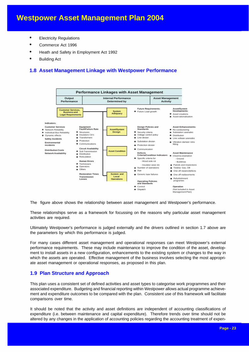
The figure above shows the relationship between asset management and Westpower’s performance.
These relationships serve as a framework for focussing on the reasons why particular asset managementactivities are required.
Ultimately Westpower’s performance is judged externally and the drivers outlined in section 1.7 above arethe parameters by which this performance is judged.
For many cases different asset management and operational responses can meet Westpower’s externalperformance requirements. These may include maintenance to improve the condition of the asset, develop-ment to install assets in a new configuration, enhancements to the existing system or changes to the way inwhich the assets are operated. Effective management of the business involves selecting the most appropri-ate asset management or operational responses, as proposed in this plan.
1.9 Plan Structure and Approach
This plan uses a consistent set of defined activities and asset types to categorise work programmes and theirassociated expenditure. Budgeting and financial reporting within Westpower allows actual programme achieve-ment and expenditure outcomes to be compared with the plan. Consistent use of this framework will facilitatecomparisons over time.
It should be noted that the activity and asset definitions are independent of accounting classifications ofexpenditure (i.e. between maintenance and capital expenditure). Therefore trends over time should not bealtered by any changes in the application of accounting policies regarding the accounting treatment of expen-
OutputPerformance
Internal PerformanceDetermined by
Asset ManagementActivity
Performance Linkages with Asset Management
Customer Services,Business and
Legal Requirements
System andLocal
Operations
Asset Condition
Asset/SystemDesign
SystemAdequacy
Indicators:
Customer ServicesNetwork ReliabilityIndividual Bus ReliabilityDynamic effects
EquipmentFault/Failure RateStructuresInsulators Cb’sTransformersProtectionCommunications
Circuit AvailabilitySub TransmissionDistributionReticulation
Human ErrorsTechniciansOperatorsOthers
Restoration TimesTransmissionLosses
Safety Incidents
Environmentalincidents
Distribution CostsNetwork Availability
Future Requirements:Future Load growth
Design Policies and StandardsSecurity criteriaVoltage control policyLine design
Substation design
Protection design
Communication
DefectsCriteria/Condition IndicatorsSpecific criteria for
- Wood pole rot
Number of operationsAge
Generic type failures
- Insulator wear etc
Operating Policiesand StandardsControlDispatch
Asset/SystemDevelopments:Asset creationsAsset rationalisation
Asset Enhancements:Re-conductoringSubstation upgradesDistributionLine voltage upgrades
Vibration damper retrofitting
Asset MaintenanceClearing vegetation
Patrols and inspectionsTesting- Gas, OillOne off repairs/defects
One off replacements
Refurbishmentprogrames
- Ground
- Buildings
Operation(Not included in AssetManagement Plan)
• Electricity Regulations
• Commerce Act 1996
• Heath and Safety in Employment Act 1992
• Building Act
1.8 Asset Management Linkage with Westpower Performance

Westpower Asset Management Plan 2004
Page - 24
2.0 LEVELS OF SERVICE
2.1 Introduction
Amendments to the Electricity (Information Disclosure) Regulations are designed to ensure that NetworkLine Companies provide an appropriate level of security of supply to their customers. The indices used are“faults per 100km”, “SAIDI” (System Average Interruptions Duration Index) and “CAIDI” (Customer Aver-age Interruption Duration Index). The regulations also require the disclosure of “Proportion of interruptionsnot restored within 3 hours” and Proportion of Interruptions not restored within 24 hours”.
These principles of condition-based maintenance provide the framework within which Westpower plans andundertakes system maintenance work. The successful application of these principles relies on
• accurate knowledge of the condition of the assets, and
• defined defect criteria for each asset type
Taken together, these determine whether work is required. Thus, the amount of maintenance work is deter-mined by and therefore is sensitive to the defect criteria. These criteria are to be documented in Westpower’smaintenance standards, which will be used as a reference point during inspections and servicing.
Once it is determined that work is required, Westpower must decide when and how the work should beundertaken. Westpower determines the preferred course of action to remedy the problem, and its priority, byanalysis and judgements taking into account the number and type of customers that may be affected due tofuture outages. Where an individual customer’s service is affected, then Westpower’s policy is to consultwith the customer affected to help ensure that the solution meets their needs while not unduly affecting othercustomers connected to the Network.
2.2 Customer Research and Expectations
In order to set reasonable security standard targets, that are compatible with end user expectations,appropriate research must be carried out.
The needs of electricity users have changed greatly over the last ten years with the rapid introduction of
diture. However it should also be noted that, under the current application of accounting policies, all activitiescould be classified as either entirely operating expenditure or entirely capital expenditure.
Similarly, the activity and asset type definitions are also independent of Westpower’s organisational structureand responsibilities, although closely aligned with the present structure. In the long run, adherence to thedefinitions will ensure that the plan remains meaningful in spite of any changes in organisational structure orresponsibilities.
The asset and activity planning categories are defined in Appendix A “Asset Types and Activity Categories”,otherwise known as the Job Costing Tree Structure. It is obvious that not all asset type and activity combina-tions are used. In addition maintenance activities can generally be planned at the detailed asset level (e.g.servicing of transformers, of circuit breakers etc), whereas development projects or programmes, whichtypically involve a combination of different asset types (e.g. lines, transformers, circuit breakers, protection,communications and network management) are kept intact rather than attempting to allocate the expenditureagainst the component asset types.
One further definitional distinction is made throughout this plan: between projects and programmes. Theword “programme” is used to define a generic activity with a generic justification, but which may apply at anumber of different sites. Replacement of defective insulators, fitting vibration dampers to lines, and upgrad-ing metering are therefore classed as such programmes. On the other hand “projects” are site (or asset)specific; for example adding a second circuit to a particular line, or upgrading a particular transformer bank.
Westpower Asset Management Plan 2004
Page - 25
technology into the domestic market. Appliances from video recorders to bread makers are now common-place in many homes and have greatly increased the sensitivity of householders to power outages andminor interruptions. Consultation with the 25 largest customers has confirmed that adoption of PLC’s andSCADA by industry has reduced tolerance to fleeting events – rotating and thermal plant that has sufficientinertia to continue through a fleeting outage will now probably be tripped when its controller loses power fora cycle or two
The degree to which modern society has come to be reliant on a secure supply of electricity was clearlyenunciated during the Auckland CBD Power Failure in February 1998. While Westpower’s area cannotboast a similar level or density of critical business users, this perception is merely a matter of degree. Thesmall gift shop owner in Greymouth, running on small margins and high overheads, is just as reliant onelectricity to power cash registers and EFTPOS terminals as the largest multinational company is forpower to it’s multi-storey tower office block.
Part of Westpower’s Vision is to “maintain an efficient and reliable electricity distribution network on theWest Coast”. In this context, “efficiency” and “reliability” are relative terms that are subject to personalperceptions. In turn, these perceptions must be viewed from the customer’s viewpoint, which must beactively sought.
Westpower intends to liaise closely with the Energy Retailers to determine the expectations of their cus-tomers, and quantify these in terms of desirable reliability indices.
2.2.1 Impact of the Proposed New Regulatory Regime
In September 2003 the Commerce Commission released its Final Threshold Decisions on the new regula-tory environment for electricity lines businesses. This consists of a targeted control regime whereby indi-vidual businesses will be investigated with a view to imposing individual price control in the event that theyexceed particular thresholds with respect to:
1. Price Path2. Reliability
At present, the proposed price path involves an annual adjustment of Consumer Price Index (CPI) – X% perannum, where X is currently set at 1% for Westpower, effectively resulting in a 1% revenue drop in real termsover each year of a five year period beginning in 2003.
If this price path is adopted in the final decision, the resulting reduction in revenue will require that Westpowercontinue to focus clearly on cost reduction, while at the same time ensuring that there is no material reductionin reliability. The professional asset management planning processes applied by Westpower over the last tenyears have placed the company in an excellent position to respond to the challenges of the new environmentwith a well-maintained asset base. New disciplines required by the regulatory environment will be incorpo-rated into future asset management plans.
2.3 Statutory Requirements
Westpower is required by statute to take all reasonable precautions to secure continuity of service. How-ever a certain level of outages is inevitable and they occur in all utilities. Westpower is subject to largeoccurrence of lightning strikes in relation to other areas of the country and these contribute to a highpercentage of fault outages. The overall level of system reliability can be measured in annual outagesystem minutes. This is the average time for which power is not supplied due to transmission systemfaults, measured as if the various outages that occur are a single outage affecting all users simulta-neously.
In addition, the following published parameters are used to measure Westpower’s performance in com-parison to other power companies.

Westpower Asset Management Plan 2004
Page - 26
SAIDI System Average Interruption Duration IndexSAIFI System Average Interruption Frequency IndexCAIDI Customer Average Interruption Duration Index
Other statutes apply to Westpower in its operation and maintenance of the distribution network.
These include the Resource Management Act.
Section 9 of RMA relates to Restrictions on use of land
1 No person may use any land in a manner that contravenes a rule in a district plan or proposeddistrict plan unless the activity is:
(a) Expressly allowed by a resource consent granted by the territorial authority responsiblefor the plan; or
(b) An existing use allowed by section 10 (certain existing uses protected).
Westpower’s Network currently crosses land governed by three different Territorial Authorities, each withtheir own District Plan and each slightly different in the rules governing the construction of new distributionlines.
Westpower’s protection of existing works are covered by Section 22 of the Electricity Act 1992 and therights of entry in respect of these works is covered in Section 23 of the Act. Prior to commencement of anyConstruction or Maintenance of Works, Westpower must give notice to other utility owners and the appro-priate Territorial Authority of its intention to commence construction or maintenance on its works.
Westpower’s Distribution Network runs throughout a very high sensitivity area along the length of theWest Coast due to the number of National Parks and their importance to the clean green image of NewZealand. Westpower does have a high regard for the environment. For this reason Westpower may berequired to use alternative methods of construction to minimise the effects on the environment. An ex-ample of this have been the placing of overhead conductors underground across the flight path of theWestland Black Petrel in the Punakaiki area. Consideration is also given to areas of high scenic value andWestpower consults and works with the Department of Conservation when working in these areas. Thismay be required for tree trimming, agreement on line routes or just general distribution line upgrades.
2.4 Strategic and Corporate Goals
Westpower is committed to an open and neutral policy of operation. Its prime responsibilities are tomanage the distribution system reliably, efficiently and economically and also to meet its users’ needs inproviding quality electricity supply services. Westpower operates to meet those needs effectively andefficiently, recognising its position as the West Coast’s dominant provider of electricity distribution ser-vices. Minimisation of industry costs is sought through the introduction of distribution automation asappropriate and the strict management of all projects to set standards of safety, performance, budget andtiming.
The present condition of any distribution line is largely a factor of its age and the environmental corrosive-ness of the locations it traverses. Figure 5.2a shows the age profile of distribution lines, by route kilome-ter.
The construction of lines in the past has often been driven by customer demands and political influences,which has resulted in the seemingly erratic nature of the line ages. The aim of the Asset ManagementPlan is to normalise the age profile of the system as much as possible by maintaining the average age ofthe network at approximately half of the weighted service life of the assets. At the same time, the condi-
Westpower Asset Management Plan 2004
Page - 27
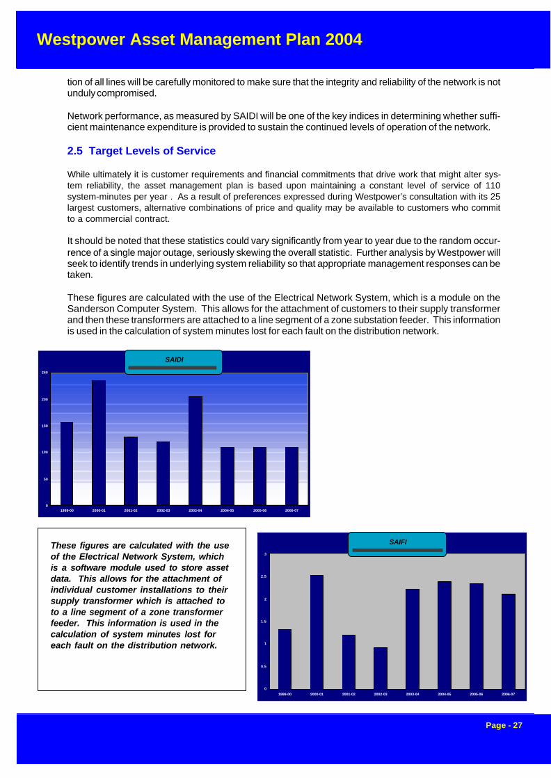
These figures are calculated with the useof the Electrical Network System, whichis a software module used to store assetdata. This allows for the attachment ofindividual customer installations to theirsupply transformer which is attached toto a line segment of a zone transformerfeeder. This information is used in thecalculation of system minutes lost foreach fault on the distribution network.
tion of all lines will be carefully monitored to make sure that the integrity and reliability of the network is notunduly compromised.
Network performance, as measured by SAIDI will be one of the key indices in determining whether suffi-cient maintenance expenditure is provided to sustain the continued levels of operation of the network.
2.5 Target Levels of Service
While ultimately it is customer requirements and financial commitments that drive work that might alter sys-tem reliability, the asset management plan is based upon maintaining a constant level of service of 110system-minutes per year . As a result of preferences expressed during Westpower’s consultation with its 25largest customers, alternative combinations of price and quality may be available to customers who committo a commercial contract.
It should be noted that these statistics could vary significantly from year to year due to the random occur-rence of a single major outage, seriously skewing the overall statistic. Further analysis by Westpower willseek to identify trends in underlying system reliability so that appropriate management responses can betaken.
These figures are calculated with the use of the Electrical Network System, which is a module on theSanderson Computer System. This allows for the attachment of customers to their supply transformerand then these transformers are attached to a line segment of a zone substation feeder. This informationis used in the calculation of system minutes lost for each fault on the distribution network.
SAIDI
0
50
100
150
200
250
1999-00 2000-01 2001-02 2002-03 2003-04 2004-05 2005-06 2006-07
SAIDI
SAIFI
0
0.5
1
1.5
2
2.5
3
1999-00 2000-01 2001-02 2002-03 2003-04 2004-05 2005-06 2006-07
SAIFI

Westpower Asset Management Plan 2004
Page - 28
Number of Faults per Feeder
0 10 20 30 40
HKK4HKK5HKK9
HKK10HKK11HKK12
ALD3ALD4DIL4
DOB1DOB3FOX1FRZ3
GYM6GYM8
GYM11GYM12GYM13
HHI1HHI3
KUM1NGH1NGH3OTI10RAP1RAP3RFT1RFT3
RSS1RSS3
WAH1WAT1WTH1
Fee
der
s
Number of Faults
CAIDI
0
20
40
60
80
100
120
1999-00 2000-01 2001-02 2002-03 2003-04 2004-05 2005-06 2006-07
CAIDI

Westpower Asset Management Plan 2004
Page - 29
3.0 PLANNING FRAMEWORK
3.1 Load Forecasting
3.1.1 Introduction
Typical customer requests relate to issues of capacity, quality and or security of supply and can lead to plansfor asset enhancement or development.
The most common upgrade in relation to capacity is that of installation of new or transferred supply trans-formers at connected points thus providing sufficient capacity to allow for future demand growth.
Supply quality typically includes provision of local voltage support in the form of regulators or capacitors tomaintain the steady state voltage within specified ranges.
Alternatively, network analysis including load projections at points of supply, power flows, network and pointof supply performance lead to options for consideration by customers and Westpower management.
Figure 3.1 Load Trends
0
10000
20000
30000
40000
50000
60000
70000
80000
kW
98 99 00 01 02 03 04 05 06 07 08 09 10 11 12 13 14
C a l e n d a r Y e a r
Load Trend(Actual/Forecast)
Dobson G r e y m o u t h K u m a r a H o k i t i k a R e e f t o n O t i r a

Westpower Asset Management Plan 2004
Page - 30
3.1.2 Historical Drivers
Future load projection is a difficult task and is based on a complex multivariate environment.
Some of the drivers that effect future load include
• climatic conditions
• economic activity
• gold prices
• coal export markets
• major step load increases/decreases
A relatively warm winter has a significant impact on winter heating loads and as a result has a major effect onthe annual peak load.
0
2000
4000
6000
8000
10000
12000
14000
kW
0
1000
2000
3000
4000
5000
6000
7000
MW
h
Jan Mar May Jul Sep Nov
Demand
Energy
Dobson
0
2000
4000
6000
8000
10000
12000
14000
kW
0
1000
2000
3000
4000
5000
6000
7000
MW
h
Jan Mar May Jul Sep Nov
Demand
Energy
Hokitika
0
2000
4000
6000
8000
10000
12000
14000
kW
0
1000
2000
3000
4000
5000
6000
7000
MW
h
Jan Mar May Jul Sep Nov
Demand
Energy
Greymouth
0
2000
4000
6000
8000
10000
12000
kW
0
1000
2000
3000
4000
5000
6000M
Wh
Jan Mar May Jul Sep Nov
Demand
Energy
Kumara
0
200
400
600
800
1000
1200
kW
0
100
200
300
400
500
600
MW
h
Jan Mar May Jul Sep Nov
Demand
Energy
Otira
0
10000
20000
30000
40000
kW
0
4000
8000
12000
16000
MW
h
Jan Mar May Jul Sep Nov
Demand
Energy
Total

Westpower Asset Management Plan 2004
Page - 31
Overall economic activity, which is to some extent also linked to gold prices and coal markets, has a filterdown effect on electricity consumption, and this can slowly take effect over the medium term.
With the relatively small overall demand of 38 MW, it is the major step load changes that have the greatestimpact on system demand. Unfortunately these are also the most difficult to predict or quantify as theydepend on investment decisions from major industries. Historically, final commitments on these projectshave been deferred to a very late stage, often involving significant last minute load revisions, leaving Westpowerin a difficult situation from a planning perspective.
A careful and rigorous approach has been taken to developing future load projections based on historicaltrends, available information and estimates on future changes.
Firstly, load trends at each Grid Exit Point over the previous 7 years are studied to try and identify historicbaseline changes. The effects of known step load increases are extracted leaving the underlying long-termhistoric load profile.
Based on this data, and general knowledge of the local economy and other drivers discussed above, anestimate is made of the likely future trend in load growth on a Grid Exit point basis. This then provides a newbaseline for further work.
3.1.3 Future Load Projections
Customer input is sought through forums where major potential users are gathered and provided with up-dates on current load trends and capacity projections. Following this, each customer or customer group (e.g.tourism) is asked to provide realistic forward load projections based on their specific industry knowledge.This information has proved to be extremely valuable, and the data collected for the current planning exer-cise has resulted in a significantly increased projection for future loads. This will have a marked impact onWestpower’s future plans for network reinforcement.
Table 3.1.1 shows the forward load projections for the next ten years based upon the information collected.
Recent economic growth on the West Coast coupled to the dairy and coal mining industries are beginning tohave a downstream effect on the general economy. Over the next three years this effect is expected tocontinue, and when added to the large step loads that are projected, the net result is a doubling of Westpower’scurrent load. Furthermore, the current transmission constraints that exist in the network feeding the WestCoast means that Westpower needs to take urgent and affirmative action to ensure that extra capacity will bemade available and an example of this is the West Coast Grid Reinforcement (WCGR) project.
The greatest challenge is determining the likelihood and size of future step changes and this is based to alarge extent on discussion with existing or potential large consumers. Early load indications provided bythese consumers are often very approximate and are subject to major variation if and when the projectproceeds.
The West Coast has a history of premature major development announcements being made, only to fallthrough when macro environmental changes occur such as the gold price dropping or a change in govern-ment policy occurs. For this reason, the projected step load changes must be viewed circumspectly untilthere is a firm commitment.
Four of the larger industrial customers have indicated they will be requiring significantly increased capacityover the next three years including
1. The Solid Energy Mine at Spring Creek is now coming on stream with full load likely to be reached in mid2004. The total load of this new mine is expected to start at around 4 MW and increase as further minedevelopment occurs. This new load is partially offset by the closure of the existing Strongman Mine.
2. GRD Macraes is now planning to reopen the Globe Progress mine with a projected demand of around 8

Westpower Asset Management Plan 2004
Page - 32
Table 3.1.1 - Load Trends and Forcasts to 2013/14

Westpower Asset Management Plan 2004
Page - 33
MW. In addition to this it is also investigating additional mining load in the Waiuta area which could add afurther 4 MW to this figure. The load is expected to come on stream in 2005.
3. The Westland Dairy Products factory at Hokitika is continuing to grow with a further 500 kW demandexpected by August 2004, followed by an additional 4 MW by August 2005. There is a high level of confi-dence in these figure based upon experience to date.
4. With the Pike River Coal Company securing critical access permission through DoC estate the next stageof the opening of a coal field at Pike River north of Greymouth has proceeded. Depending on the finaloutcome of further consents and other issues, a demand of 5 MW is expected around 2006.
As can be readily noted, the projected additional demand over the next three years could potentially reach ashigh as 40 MW, and considering that the total system demand is around 38 MW with around 24 MW of thisfed by Transpower, the capacity of the transmission network will effectively need to triple of the demand is tobe met.
This projection forms a key driver for investment in sub-transmission infrastructure over the next three yearsand associated projects are expected to dominate Westpower’s capital expenditure program.
3.1.4 Options for Handling Load Increases
A number of strategies are available for dealing with load increases and include:
• Economic tariff structure models
• Demand Side Management
• Line Drop Compensation
• Distributed Generation
• Voltage Regulation/Support
• System Reconfiguration
• Reactive Compensation (Capacitors)
• Reconductoring
• Overlaying with a higher voltage
Each of these options is carefully evaluated based on economic efficiency and technical performance. Wher-ever possible, capital intensive development is delayed until absolutely necessary and non-asset intensivesolutions used where these are not incompatible with future development plans.
Very large load increases are unlikely to be handled by the present Transpower transmission infrastructure,which is already voltage constrained. To provide for such load increments, either further local generation ora major upgrade to the transmission network will be required. This is likely to involve both the upgrade of theTranspower Dobson-Inangahua Circuit to 110 kV and for Westpower to construct its own 110 kV transmis-sion line from Inangahua to Dobson along with a 110/33/11 kV Substation at Reefton.
Ignoring such increases, the first three solutions identified above are essentially non-asset intensive
Demand based tariffs give the end user strong incentives to reduce peak demand and maximise plant loadfactors. This results in less peak demand and better regulation on the Westpower network.
Use of Demand Side Management is linked to the tariff structure and allows the plant or Westpower to controlits internal demand by shedding nonessential load at peak periods.
Line Drop Compensation (or LDC) can be used in specific circumstances to boost the sending end voltageon a feeder to improve down line regulation. This effectively increases the available capacity on a feeder.

Westpower Asset Management Plan 2004
Page - 34
Westpower has also begun a programme of installing capacitors at strategic points in the network wherevoltage constraints are present or imminent. In some cases, load growth for a particular installation is depen-dent upon increased reactive support, and the consumer is required to contribute to the capital expenditureinvolved.
Reconductoring and overlaying with a higher voltage are very asset intensive, and often cannot be justified interms of the cost involved. In many cases this cost must be borne by the consumer requesting the supply,and becomes their decision in the final analysis.
Distributed Generation is seen as an excellent means of reducing demand on the Transpower network andenhancing the performance of Westpower’s distribution network. As such, Westpower actively supports thisapproach, and a transparent pricing methodology is being developed to ensure that there are low entrybarriers for new generators, and that they receive the full avoided cost of transmission benefits that they areentitled to.
Technical requirements for connection of distributed generation are based on the industry standard EEAGuidelines.
Notwithstanding the above comments, the quantum of the increase Westpower is currently facing, as de-picted in Figure 3.1, means that energy conservation, distributed generation or small renewable generationprojects are not, in themselves, viable solutions to the constraints now being faced, but they do improve thequality of supply and reduce the marginal costs and losses associated with transmitting energy into the area.
Any capital expenditure must be fully justified and in normal circumstances such a project is expected to addvalue to the company by providing a Return on Investment (ROI) of at least 7% after tax. Competing projectsare compared using Discounted Cash Flow (DCF) studies, and this is used to prioritise the order of projectsin terms of Net Present Value (NPV). This determines which projects can be funded out of a limited capitalbudget. The consumer must meet any shortfalls if they are the initial drivers for the upgrade.
Projections of future loads on the system scenarios have been developed and modified where necessary forthis plan. The load growth projections were used as a basis for determining the likely timing of those projects,which are justified by load growth.
3.2 Design Policy and Planning Guidelines
The following design policies act as drivers for Asset Management purposes.
3.2.1 Security Guidelines
The security guidelines are the basis for analysis and for determining the future performance of the distribu-tion system.
The security guidelines adopted for planning purposes are outlined on the following page. Customers whoare prepared to enter into commercial agreements can be provided with alternative levels of security

Westpower Asset Management Plan 2004
Page - 35
3.2.2 Voltage Policy
Programmes and projects are typically justified on the basis of the following benefits from improved voltagelevel or controls:
Ø the ability to meet any regulatory requirements with respect to voltage standards
Ø specific customer requirements which the customer is willing to pay for
Ø savings in losses
Ø improvements in transmission circuit capacity and the consequential deferment of capital expendi-ture
Most initial customers were connected to the system at 400 V and Westpower undertake to control this withina range of +/- 6%.
For 11kV and higher voltage customers, the design voltage range is from 96% to 102% of rated voltage.
3.2.3 Voltage Control
Supply Transformers
In order to allow the system to be operated as efficiently as possible, all new Zone Substation transformerswill be purchased with on load tap change facilities (OLTC) with HV tapping ranges of -15% to +5%.Where applicable, Line Drop Compensation techniques are used to improve downline regulation and reducelosses.
Distribution transformers will have off load tapchangers to a range of –7.5%. These will allow greater flexibil-ity in the operation of the main distribution system while meeting the obligations to customers.
Where obligations to existing customer to control the connection voltage level restricts the flexibility of opera-tion of the distribution system then Westpower may replace the supply transformer with one, which is better,suited to the situation.
Security Guidelines for Distribution Planning
Load (MW) BasicSecurity
Level
TransmissionCircuits
Busbars Transformers
Less than 10 n One circuit One Bus or Bus section 4 x 1-phase units or
1 x 3-phase unit, if backed upfrom alternative supply points
10 to 300 n-1 circuits Two circuits Two busbars or bus sections
More than300
n-2 circuitsn-1 lines
Three circuitson at least two
routes
One redundant bus or bus section,such that supply not lost after a
single contingency while one bus
out of service for maintenance
7 x 1-phase units or
2 x 3-phase units
Firm supply of peak demandusing any short term overload
capacity

Westpower Asset Management Plan 2004
Page - 36
Direct Customer Connections
For new customers Westpower will require agreement to the standard tolerances on the system voltage atthe point of customer connection.
However if a closer tolerance is required, the customer will be required to pay the additional cost associatedwith the installation of any voltage control equipment necessary to achieve this.
For existing customers Westpower will continue to observe the agreed supply voltage tolerances by restrict-ing the system voltage variations as far as practicable.
3.2.4 Protection Policy
Protection systems for the Westpower distribution network will be designed to;
Ø detect faults between phases or between phases and earth
Ø allow plant to carry rated emergency load without disconnection
Ø disconnect faulty plant from the system with minimum damage
Ø disconnect faults quickly enough to avoid system instability
Ø minimise the likelihood of personal injury or property damage
Ø minimise supply interruptions
Ø detect abnormal operating conditions which could result in plant damage
Ø disconnect only plant item effected
Ø prevent damage due to faults
Ø operate reliably as economically justified
Sensitivity
Protection sensitivity will be adequate for each application but not so sensitive that it will result in tripping ofcircuit breakers unnecessarily at normal load levels.
Abnormal Conditions
For transformers the protection will be set to detect conditions which may lead to overheating and possiblefailure of equipment. No overload protection will be provided for transmission circuits.
Selectivity
The protection will be set so that when all protective relays and circuit breakers are functioning as designed,the protection system will clear only the faulted equipment from the system.

Westpower Asset Management Plan 2004
Page - 37
3.3 Strategic Plans by Area
3.3.1 Reefton Network
In 1999, Westpower extended its 33 kV sub-transmission network in the Grey Valley as far as Reefton andbuilt a new Zone Substation on the Transpower Reefton Substation site. The Reefton area demand is cur-rently within the supply capability of this Zone Substation and associated 11 kV network. The current de-mand of 2.3 MW can increase to 3.0 MW before further voltage support measures such as reactive compen-sation are required.
Development of the 5 MW Macraes Gold Project at Reefton will require significant strengthening of thesupply into the Reefton area. After considerable investigation, the solution chosen is for Westpower to con-struct a 110 kV spur from Inangahua to Reefton with a 20 MVA 110/33/11 kV Zone Substation at Reefton.This work will be carried out in such a way as to be compatible with Transpower’s own transmission develop-ment in the area to ensure that asset ownership does not get in the way of a superior technical and economicsolution.
The future 11 kV distribution capacity to the Ikamatua area is limited by voltage support considerations. Anew Zone Substation will be required at Blackwater, when load growth of around 200 kW is realised. Basedon current trends it is expected this will occur around 2009. This project is likely to be initiated, in any case,by Oceana Gold requiring power for the re-opened Waiuta Gold Mine.
3.3.2 Greymouth Network
Several significant coal-mining projects are in the planning stages including Pike River and the Grey CoalCompany at Rapahoe. The estimated loads for these projects are 5 MW for Pike River and 1 MW for GreyCoal (after allowing for the decommissioning of the existing Strongman II Mine). In addition, base loadgrowth, and continuing improvement in the exotic timber milling and tourism industries will require significantcapacity increases in the short term. The existing 33 kV transmission network can support these loads,however, this does not also hold true for the existing 66 kV transmission network into the West Coast, whichis severely constrained.
If a circuit breaker fails to operate correctly, it is desirable that the remaining equipment operates selectively.
Fault Clearance Time
Ø clearance times will be limited so that damage at the point of fault is reduced to that economicallyjustified by the increasing protection expenditure
Ø clearance times will be such that the short time rating of equipment is not exceeded
Ø clearance time will be short enough to ensure that system stability is maintained for all foreseeablefault conditions, where the fault is cleared by the main protection It is desirable that this time is alsoshort enough if the fault is cleared by backup protection
Risk to People
The protection system will always be set to comply with the Electrical Supply Regulations. Particular atten-tion will be paid to providing fast and reliable protection in urban areas.
Protection Reliability
Protection systems will be designed to have a high degree of reliability because of the extreme conse-quences of failure to operate.

Westpower Asset Management Plan 2004
Page - 38
Accordingly, the 66 kV transmission network on the West Coast will need upgrading immediately if any of themajor new loads proceed, and certainly within three years just to cover base load growth. To achieve this,after commissioning of the new Reefton Substation, the Westpower 110 kV line will be extended down toDobson. Contemporaneously, Transpower are planning the conversion of their Dobson-Inangahua line to110 kV, as well as installing a 110/66 kV interconnecting transformer bank at Dobson. This will result insignificantly improved transmission capacity and security with two 110 kV transmission lines into the area tothe whole central West Coast region.
This development has been allowed for in the design of the Transpower Dobson Substation.
To support the more demanding communication requirements of the transmission development projects, anew digital radio backbone is being installed, initially serving the Greymouth and Hokitika areas, but de-signed to be extended to other areas of the network as required. This will replace aging analogue UHF radiosthat have become technically obsolete.
Older distribution lines will be repaired and refurbished as required by ongoing condition assessment.
3.3.3 Hokitika Network
The recent completion of the Westland Dairy Factory Supply, comprising a new Westpower 30 MVA 66/33/11kV substation at the East Town Belt of Hokitika, has vastly improved both the capacity and security of supplyto the town of Hokitika and surrounding districts including all of South Westland. This will also provide forcontinuing expansion at the Westland Dairy Products factory, along with downstream growth in the dairyindustry in general, for at least the next ten years.
With the exception of some additional strengthening required in the Kokatahi/Kowhitirangi and Ruatapuareas due to industrial and farming growth over the next few years, there is little major work required withinthe planning period.
The South Westland Grid Reinforcement Project (SWGR), when it proceeds, will involve an extension of theHokitika 66 kV bus and provision of an additional 66 kV feeder
3.3.4 South Westland Network
After the amalgamation of the Grey, Westland and Amethyst Boards in 1972, it was found that the infrastruc-ture assets in South Westland were in a very poor condition. Considerable expenditure has occurred overthe last thirty years to bring the reticulation system up to an acceptable standard.
Notwithstanding the above, significant load growth due to expansion in the tourism industry is currently beingexperienced and the network is approaching voltage constraint limits under certain operating scenarios. Inview of this, system planning studies have identified the need for additional voltage support in the short term,and this will be provided by a mixture of fixed, switched and variable capacitor banks at both 11 kV and 400V.
To support the load growth at Fox Glacier in particular, a new 33/11 kV zone substation has been constructedand the existing line from Franz Josef to Fox Glacier upgraded to operate at 33 kV. The reduction in both realand reactive power losses incurred by the current 11 kV operating voltage on this line will significantly im-prove voltage regulation throughout all of South Westland, and defer other more costly reinforcement projects.The construction of this substation will also facilitate expanded local hydro generation in the area resulting incollateral benefits to Westpower’s network.
Depending upon actual load growth, it is possible that the South Westland Grid Reinforcement Project (SWGR)may be required toward the end of the planning period and this will involve upgrading the Hokitika-Harihariline to 66 kV along with converting of the Waitaha and Harihari Substations to 66 kV operation.
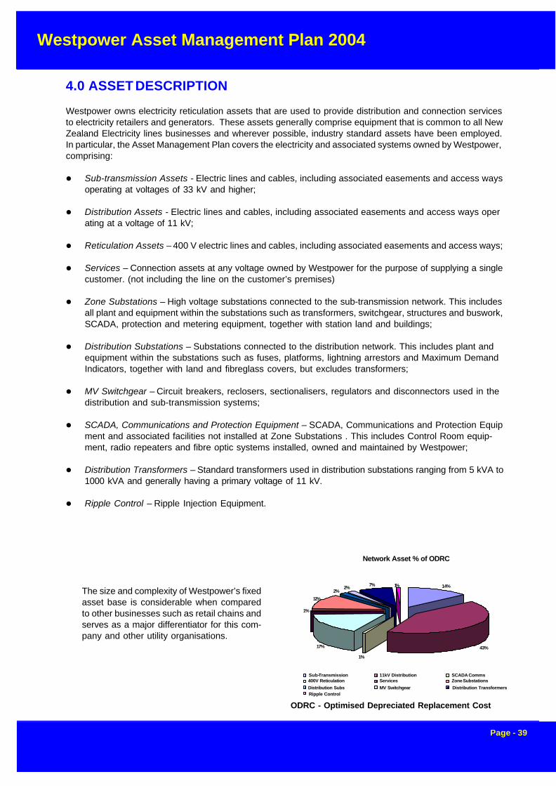
Westpower Asset Management Plan 2004
Page - 39
4.0 ASSET DESCRIPTION
Westpower owns electricity reticulation assets that are used to provide distribution and connection servicesto electricity retailers and generators. These assets generally comprise equipment that is common to all NewZealand Electricity lines businesses and wherever possible, industry standard assets have been employed.In particular, the Asset Management Plan covers the electricity and associated systems owned by Westpower,comprising:
l Sub-transmission Assets - Electric lines and cables, including associated easements and access waysoperating at voltages of 33 kV and higher;
l Distribution Assets - Electric lines and cables, including associated easements and access ways operating at a voltage of 11 kV;
l Reticulation Assets – 400 V electric lines and cables, including associated easements and access ways;
l Services – Connection assets at any voltage owned by Westpower for the purpose of supplying a singlecustomer. (not including the line on the customer’s premises)
l Zone Substations – High voltage substations connected to the sub-transmission network. This includesall plant and equipment within the substations such as transformers, switchgear, structures and buswork,SCADA, protection and metering equipment, together with station land and buildings;
l Distribution Substations – Substations connected to the distribution network. This includes plant andequipment within the substations such as fuses, platforms, lightning arrestors and Maximum DemandIndicators, together with land and fibreglass covers, but excludes transformers;
l MV Switchgear – Circuit breakers, reclosers, sectionalisers, regulators and disconnectors used in thedistribution and sub-transmission systems;
l SCADA, Communications and Protection Equipment – SCADA, Communications and Protection Equipment and associated facilities not installed at Zone Substations . This includes Control Room equip-ment, radio repeaters and fibre optic systems installed, owned and maintained by Westpower;
l Distribution Transformers – Standard transformers used in distribution substations ranging from 5 kVA to1000 kVA and generally having a primary voltage of 11 kV.
l Ripple Control – Ripple Injection Equipment.
The size and complexity of Westpower’s fixedasset base is considerable when comparedto other businesses such as retail chains andserves as a major differentiator for this com-pany and other utility organisations.
Network Asset % of ODRC
14%
43% 1%
17%
1%
7% 12%
2% 1% 2%
Sub-Transmission 11kV Distribution SCADA Comms 400V Reticulation Services Zone Substations Distribution Subs MV Switchgear Distribution Transformers Ripple Control
ODRC - Optimised Depreciated Replacement Cost

Westpower Asset Management Plan 2004
Page - 40
Westpower own assets throughout the length of the West Coast of the South Island, and its area extendsabout as far as the distance from Christchurch to Dunedin as shown in Figure 4.0a
4.1 Sub-transmission Assets
Westpower owns two distinct classes of sub-transmission assets, running at 66 kV and 33 kV respectively.The 66 kV assets are leased back to Transpower for operation as part of their West Coast transmissionnetwork.
4.1.1 Asset Justification
Subtransmission assets, either at 66kV or 33 kV, are required to transmithigh levels of electrical energy oversignificant distances, prior to break-ing the voltage back down to 11 kVfor local distribution. The long dis-tances involved in reticulation of elec-tricity on the West Coast mean thatthese assets are essential for thecapacity and load diversity involved.
4.1.2 66 kV Lines
Westpower owns three overhead 66kV sub-transmission lines. Two ofthese are connected to theWestpower Kumara Substation, whileanother is an extension of theTranspower owned AHA-OTI circuit.Figure 4.1a shows the locations of these as-sets.
As discussed above, all three of these assets are currently leased to Transpower on a long-term leasearrangement.
Figure 4.0a
Figure 4.1a - Westpower’s 66 kV Assets

Westpower Asset Management Plan 2004
Page - 41
The line between Greymouth and Kumara is a 25 km hardwood-pole line strung with Dog ACSR conductor. This was constructedin 1977 to connect the Kumara Power Station to the WestpowerGreymouth Substation and then to the Transpower Grid.
The 66 kV double-circuit treated hardwood pole line betweenKumara and Kawhaka was commissioned in 1997,and this was subsequently leased to Transpower,allowing them to reconfigure the grid on the WestCoast.The line is 11km long and uses Iodine AAAC con-ductor on both circuits.
The most recently constructed 66 kV line, betweenTwo Mile and Hokitika substation, was completedin July 2002. This too is a double circuit line, how-ever pre- stressed concrete poles have been usedto support the 7.8 km of Iodine AAAC conductor.Westpower has no underground cables at trans-mission voltages of 66kV and above.
4.1.3 33 kV Lines and Cables
There are two general areas served by Westpower’s33 kV sub-transmission network, one based aroundthe Dobson and Grey Valley areas and the otherserving South Westland
Figures 4.1c and 4.1d show the geographical spreadof these two assets.
The Transpower Dobson Point of Supply serves asthe hub of the northern sub-transmission systemand is used to feed substations at Rapahoe,Ngahere, Reefton and Arnold.
The line to Arnold was originally built in the 1930’sand uses 7/.080” copper conductor. Except for ashort length of Mink ACSR line over Mt Hercules andsome fully insulated 33 kV overhead line in South Westland, the rest of the sub-transmission lines are strungwith either Dog ACSR or Iodine AAAC conductor.The 33 kV sub-transmission line from Hokitika to Harihari originally constructed in 1966 was purchased from
Figure 4.1b - Kumara -Kawhaka 66kV line during
construction
Table 4.2c: 66 kV Lines Summary
Type Route Length (km)
Light Overhead 0
Medium Overhead 42
Heavy Overhead 0
Figure 4.1c - Northern 33 kV Network

Westpower Asset Management Plan 2004
Page - 42
Figure 4.1f Hendrix Spacer Cable
Transpower. The large majority of the remaining33 kV assets have been constructed since 1983and are mainly of concrete pole construction.
Westpower uses some short lengths of PILCSWA33 kV underground cable as feeder cables at itsDobson Substation.
4.1.3.1 Aerial Bundled Conductor (ABC) andHendrix Cable Systems
In South Westland, there are two sections of fullyinsulated 33kV overhead conductor. The first is afully insulated cable, which is bundled together toform three phases, and then suspended betweenpoles and an example of this type of asset is shownin Figure 4.1e.
By using this specialist conductor, Westpower wasable to mitigate the environmental effects on a sen-sitive environment with high scenic values. In fact,this line runs through a National Park.
A 2 km stretch of cable runs close to Lake Wahapo.Similarly, a 3.6 km section of line that traversesLake Mapourika in South Westland was replacedwith a Hendrix Cable in 2000 and is shown in Fig-ure 4.1f. This is often called Spacer Cable con-struction, and uses three separate, fully insulatedconductors, held apart by insulated spacers.
Figure 4.1d Southern 33 kV Network
Figure 4.1e – Aerial Bundled Cable inSouth Westland

Westpower Asset Management Plan 2004
Page - 43
Figure 4.2a - Northern section of Westpower’s distribution line assets

Westpower Asset Management Plan 2004
Page - 44
Figure 4.2b - Southern section of Westpower’s distribution line assets

Westpower Asset Management Plan 2004
Page - 45
4.2.1 Asset Justification
These are core assets for lines businesses and comprise the distribution lines and cable that deliver electric-ity at 11 kV to the distribution substations that supply 415 V or 230 V to individual installations. These assetsare therefore essential to the operation of the network.
4.2.2 11 kV Overhead Lines
Table 4.2c above lists the total overhead distribution line assets owned by WestpowerWestpower owns a large variety of distribution lines and cables that cover a wide age profile. Overhead linescover three broad groups including
l Early hardwood pole lines
l Concrete Pole lines
l Treated Softwood Pole linesSince 1972, most of the major lines have beenreconstructed with concrete poles and AAAC orACSR aluminium conductors. Notwithstandingthis, there are some notable exceptions such asthe Fox-Paringa and Coast Road lines whichused treated softwood poles for environmentaland constructability reasons.
All of the major 11 kV feeder distribution lineshave been completely rebuilt over the last 25years and this has resulted in a few remainingpockets of earlier hardwood lines in theGreymouth and Reefton areas.
Softwood or concrete poles are used for all re-placement or new construction work and thesetypes make up over 60% of the pole population.An example of a modern construction is shownin Figure 4.2eFigure 4.2e – Modern Pole Construction
Table 4.2c: 11 kV Lines Summary
Type Route Length (km)
Light Overhead 1056
Medium Overhead 361
Heavy Overhead 5
4.2 Distribution Assets
Electric lines and cables, including associated easements and access ways operating at a voltage of 11 kVmake up the bulk of Westpower’s infrastructure assets, in terms of both value and number.
Figure 4.2a and 4.2b on the previous pages show the extent of Westpower distribution line assets spreadthroughout the length of the West Coast.
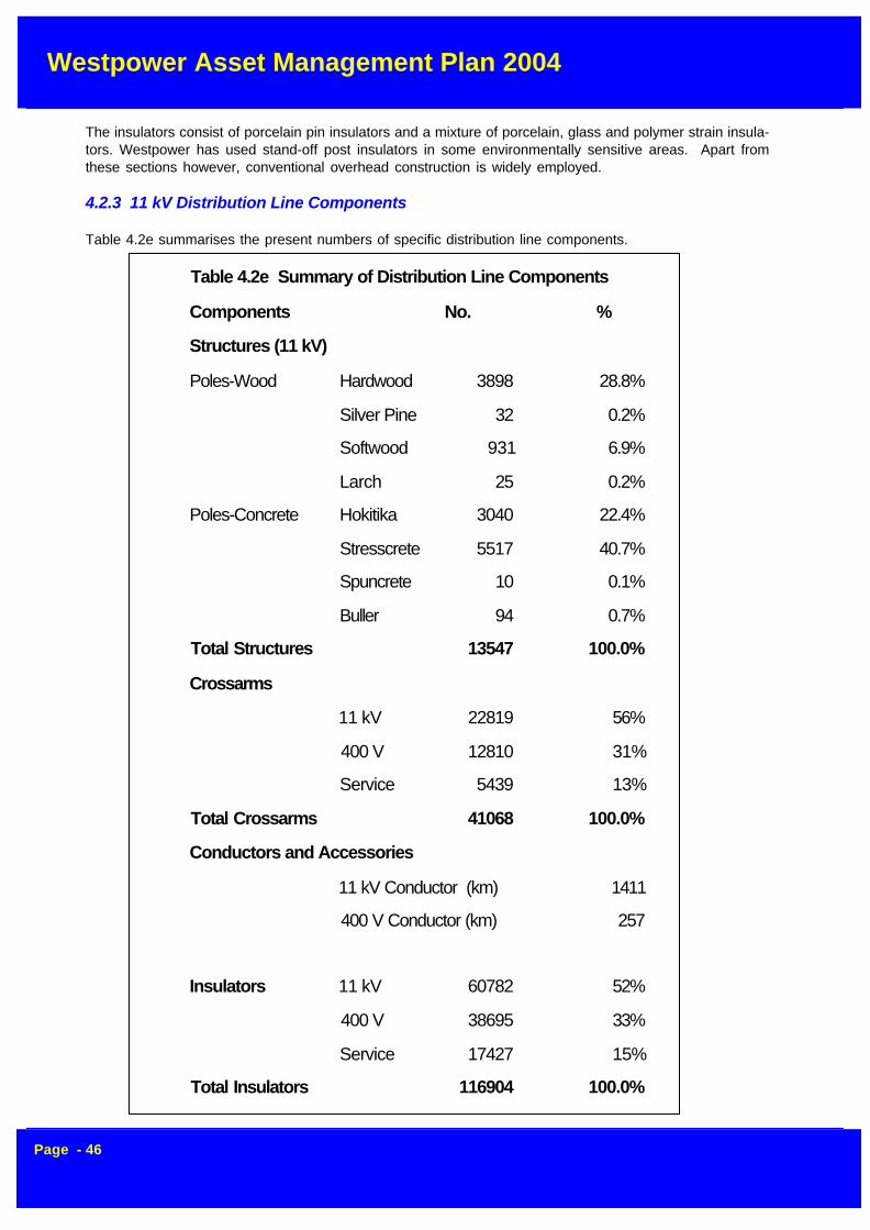
Westpower Asset Management Plan 2004
Page - 46
The insulators consist of porcelain pin insulators and a mixture of porcelain, glass and polymer strain insula-tors. Westpower has used stand-off post insulators in some environmentally sensitive areas. Apart fromthese sections however, conventional overhead construction is widely employed.
4.2.3 11 kV Distribution Line Components
Table 4.2e summarises the present numbers of specific distribution line components.
Table 4.2e Summary of Distribution Line Components
Components No. %
Structures (11 kV)
Poles-Wood Hardwood 3898 28.8%
Silver Pine 32 0.2%
Softwood 931 6.9%
Larch 25 0.2%
Poles-Concrete Hokitika 3040 22.4%
Stresscrete 5517 40.7%
Spuncrete 10 0.1%
Buller 94 0.7%
Total Structures 13547 100.0%
Crossarms
11 kV 22819 56%
400 V 12810 31%
Service 5439 13%
Total Crossarms 41068 100.0%
Conductors and Accessories
11 kV Conductor (km) 1411
400 V Conductor (km) 257
Insulators 11 kV 60782 52%
400 V 38695 33%
Service 17427 15%
Total Insulators 116904 100.0%

Westpower Asset Management Plan 2004
Page - 47
4.2.4 11 kV Cables
Cable makes up a very small portion of Westpower’s total high voltage assets, and is generally limited toCentral Business Districts or Zone Substations. There are however some exceptions to this, such as therecreational areas of Moana and Punakaiki.
Throughout the 1980’s Westpower, had a policy of undergrounding urban areas and this resulted in a signifi-cant amount of the overhead reticulation in those areas being replaced. As a case in point, the majority ofHokitika is reticulated underground, and underground high voltage cables are used throughout the CBD andpast the airport.
While some of the older 11 kV cables around Greymouth were installed in the 1950’s, many of these havesince been overlaid or replaced with modern equivalents. Paper insulated lead sheathed cable was thestandard for normal distribution purposes until the mid-1980’s when XLPE insulation gradually came intovogue.
4.3 Reticulation Assets
These assets include 400 V overhead lines and cables used to reticulate electricity to the boundary ofconsumer’s premises.
4.3.1 Asset Justification
Once the electricity is broken down from 11,000 Volts to 230 Volts at distribution substations, the 400 voltreticulation assets comprising overhead lines and cables are necessary to deliver electricity to the bound-aries of individual installations. As such, these assets are a core part of Westpower’s network.
4.3.2 Overhead 400 V Lines
Westpower uses a conventional overhead low voltage configuration with insulated conductors and cross-arms; Aerial Bundled Cable (ABC) construction techniques are not employed.
In terms of conductor selection, copper was used extensively until the mid-1970’s, but was gradually re-placed with PVC covered aluminium because of economic and constructability considerations.
Virtually all of the low voltage networks from Hokitika south, and some within the urban area of Greymouthhave been replaced in the last twenty years with underground cable. Long lengths of low voltage line in thesatellite towns of Greymouth including Cobden, Blaketown and Runanga were rebuilt with new overhead LVconstruction in the 1990’s.
However, in some older areas such as the towns of Dobson and Reefton, there are still sections of olderwood-pole low-voltage reticulation.
4.3.3 Underground 400 V Cables
A variety of underground cable types have been used for low voltage reticulation spanning a period of some30 years.
In the early days, single-core aluminium cables, with either a stranded or solid core was widely used. Overtime however, multi-core cables became popular because of the cost advantages.
A standard cable now used in residential areas is 95mm2 stranded aluminium with a copper neutral screen.For denser CBD areas such as the town of Greymouth, four-core 185mm2 cables were used.

Westpower Asset Management Plan 2004
Page - 48
Currently, all new urban subdivisions are reticulated underground as a requirement of the appropriate DistrictPlan.
4.4 Services
This asset consists of the equipment used to connect approximately 10,500 consumers to Westpower’snetwork.
The major component of this asset is the service protective device, which may be one of the following
l 400 V rewireable pole fuse
l 400 V HRC pole fuse
l 11 kV Drop-Out Fuse
l 11 kV Circuit Breaker
In the last case, the consumer would own the 11kV circuit breaker and in this situation the connection assetwould be an 11kV disconnector.
The service line on the premises of the consumer is owned and maintained by the consumer.
4.4.1 Asset Justification
Services include assets required to make the final connection between the customer’s installation andWestpower’s network. These are necessary for an individual customer to take supply from Westpower.
4.5 Zone SubstationsZone Substations are used to transform power from transmission and sub-transmission voltages of 33kVand higher down to Westpower’s standard distribution voltage of 11 kV.
These substations comprise buildings, switch-yard structures and associated hardware, high voltage circuitbreakers, power transformers, instrument transformers, and a multitude of other associated power supplycabling and support equipment. Furthermore, the substations range in size from 1 MVA to 20 MVA and areused to feed large areas of Westpower’s network thus playing a critical role in the overall reliability ofWestpower’s network.
Fig 4.5a shows the location and size of Westpower’s 15 Zone Substations.
Fig 4.5b show Westpower’s Zone Substation at Greymouth which houses two 10 MVA 66/11 kV transformerbanks and was constructed in 1977.
The latticework steel structure is unique within Westpower’s area and reflects the common standards usedby Transpower at the time.
The high voltage bus and equipment in this substation is leased to Transpower for operation as part of thenational grid.
At the other end of the scale are the 1 MVA 33/11 kV substations utilised at sites such as Whataroa Substa-tion and this is shown in Fig 4.5c.
Installations at Harihari, Ross and Waitaha use similar standard designs to the Whataroa site.
These substations use a small transformer with an external regulator for economic reasons.
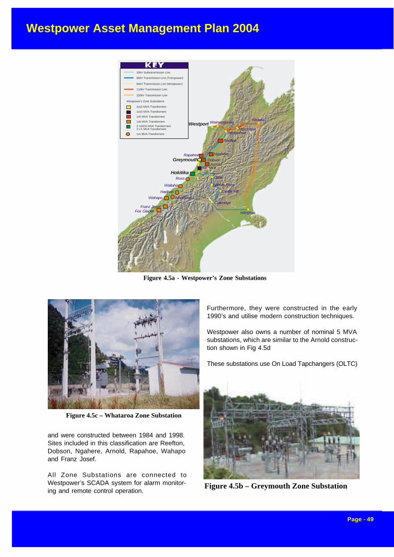
Westpower Asset Management Plan 2004
Page - 49
Furthermore, they were constructed in the early1990’s and utilise modern construction techniques.
Westpower also owns a number of nominal 5 MVAsubstations, which are similar to the Arnold construc-tion shown in Fig 4.5d
These substations use On Load Tapchangers (OLTC)
and were constructed between 1984 and 1998.Sites included in this classification are Reefton,Dobson, Ngahere, Arnold, Rapahoe, Wahapoand Franz Josef.
All Zone Substations are connected toWestpower’s SCADA system for alarm monitor-ing and remote control operation.
Figure 4.5b – Greymouth Zone Substation
Figure 4.5c – Whataroa Zone Substation
Figure 4.5a - Westpower’s Zone Substations
Wahapo
Franz JosefColeridge
Islington
Castle Hill
Arthurs Pass
Otira
DobsonArnold
Kumara
Harihari
Waitaha
Ross
Reefton
Ngahere
InangahuaMurchison
KikawaWaimangaroa
Greymouth
Westport
Hokitika
33kV Subtransmission Line
66kV Transmission Line (Transpower)
66kV Transmission Line (Westpower)
110kV Transmission Line
220kV Transmission Line
Westpower’s Zone Substations
2x10 MVA Transformers
1x10 MVA Transformers
1x5 MVA Transformers
1x6 MVA Transformers
2 x10/15 MVA Transformers2 x 5 MVA Transformers
1x1 MVA Transformers
Rapahoe
Whataroa
Fox Glacier

Westpower Asset Management Plan 2004
Page - 50
Table 4.5b Circuit Breakers
Type 66 kV 33 kV 11 kV Total Units
Outdoor
SF6 7 0 0 6
Minimum Oil 3 0 0 4
Oil Recloser 0 6 0 6
Vacuum Recloser 0 13 18 31
Total Outdoor 10 19 18 47
Indoor
SF6 0 0 4 4
Vacuum 0 0 24 24
Metalclad Panels (Bulk Oil) 0 0 3 3
Total Indoor 0 0 31 31
Total Circuit Breakers 10 23 49 82
4.5.1 Asset Justification
Zone Substations are required to break downsubtransmission voltages (66,000 volts and 33,000volts) to the local distribution voltage of 11,000 volts.These assets form an integral part of the supply chainand are strategically spread throughout Westpower’sarea
4.5.2 Power Transformers
Westpower has 18 power and earthing transform-ers installed at its Zone Substations, (as opposed todistribution transformers, which are used in Distri-bution Substation). Of these, 11 are fitted withon-load tapchangers.
Table 4.5a gives the general details of thepower transformer population.
Table 4.5a Summary of Zone Substation Transformers
Type 66 kV 33 kV 11 kV Total Units
Power Transformers
Supply 3 phase 5 14 0 19
Subtotal 5 14 0 19
Other Transformers
Earthing 0 2 1 3
Regulating 0 0 6 6
Subtotal 0 2 7 9
Total Transformers 5 16 7 28
All of the larger (above 1 MVA) power trans-formers are three phase units fitted withon-load tapchangers.
Earthing transformers are used at Zone Sub-stations connected to generating stations toprovide appropriate source earthing require-ments. These are high impedance units de-signed to limit earth fault currents and pro-vide reactance earthing for injection into thenetwork. They also comprise a 400 V sec-ondary to provide local service to the site.
4.5.3 SwitchgearTable 4.5b summarises the present asset mixfor this equipment used in Zone Substations
4.5.4 Oil Containment
Oil containment facilities have been installed at major substations constructed since 1993, including Dobson,
Figure 4.5d – Arnold Zone Substation

Westpower Asset Management Plan 2004
Page - 51
Figure 4.8a – Typical
Extra assets required for these substations are
l Concrete pad
l Fibreglass cover
l HV and LV Feeder Cables
l DIN LV Fusegear
Table 4.6d lists the overall range of distribution substation sites, sub-totalled by number and total capacity.
All substation data including servicing records are stored in the Elec-trical Network System (ENS) and Service Maintenance Management(SMM) System. In addition, all substations are logically linked to indi-vidual Installation Control Points (ICPs) for the purposes of outagenotifications and network reliability analysis.
Reefton, Arnold and Hokitika substations. These facilities have also been retrofitted at the Greymouth,Kumara, Wahapo, Rapahoe, Ngahere and Franz Josef Substations.
4.6 Distribution Substations
Distribution Substations generally consist of a distribution transformer and associated equipment including
l 11kV Drop Out Fuses
l Lightning Arrestors
l Low Voltage Fuses
l Support Crossarms
• Earthing System
Figure 4.6a shows a typical three-phase distribution substation.
The fitting of lightning arrestors is now standard on all substations, and a retrofitting programme over recentyears has ensured that virtually every existing substation meets this requirement.
In addition to these items, larger substations rated at 100 kVA and above, such as that shown in Figure 4.6bwill often have the following additional components:
l Galvanised Steel Platform
l Maximum Demand Indicator
Because of the extremely corrosive coastal environment that Westpower is confronted with, galvanised steelor coreten tanks are standard for all distribution transformers.
For large substations over 200 kVA, pad-mount construction is normally used, where the transformer isplaced on the ground under as shown in Figure 4.6c.
Figure 4.6a - TypicalDistribution Substation

Westpower Asset Management Plan 2004
Page - 52
Figure 4.8b – DistributionFigure 4.6b - Distribution Substation>100 kVA < 200 kVA
Figure 4.6c - Pad Mount Substation
Table 4.6d - Age Distribution of Transformers
Age Distribution of Westpowers Transformers
0%
2%
4%
6%
8%
10%
12%
14%
16%
18%
20%
0-5 6-10 11-15 16-20 21-25 26-30 31-35 36-40 41-45 46-50 51-55 56-60 61-65 66+
Age (years)
% o
f To
tal
Quantity MVA

Westpower Asset Management Plan 2004
Page - 53
4.6.1 Asset Justification
Distribution Substations are required to break down the distribution voltage of 11,000 volts to either 400 voltsor 230 volts suitable for supplying individual installations.
4.7 Medium Voltage Switchgear
This class of equipment includes:
l Regulatorsl Disconnectorsl 11kV circuit breakersl Reclosersl Sectionalisersl Ring Main Unitsl 11kV dry fuse units
These are not installed at Zone Substations. (MV switchgear within Zone Substations is included in thatclassification).
Line regulators are installed on long 11kV lines with significant loads near the end. Westpower has two suchinstallations at Longford Corner (near Kokatahi), at Cronadun (north of Reefton).
In general, disconnectors are standard two or three post units made by Schneider (ex Canterbury Engineer-ing), but mainly type DA2. Some units are fitted with “CE Break” load-break heads.
Westpower has used a range of circuit breaker equipment over the last fifty years, but has now standardisedon the use of Cooper Power Systems vacuum reclosers and bulk oil sectionalisers, which make up the majorshare of the population.
Small numbers of old 11 kV circuit breakers are still in use as distribution substation HV breakers and in thetest bay.
Table 4.7a summarises the present population of MV Switchgear
The Ring Main Units are either Reyrolle or ABB “SD” type and are all less then 25 years old.
Some Hazemeyer dry type equipment has also been installed in the network, but its use is not widespread.
A variant of this equipment made by Krone has been phased out and replaced because of reliability con-cerns.
4.7.1 Asset Justification
These assets cover a diverse range of devices, but generally include switches of various types that are usedto protect and sectionalise the network. In the event of a fault on the network, fuses, reclosers and sectionalisersare needed to isolate the faulted section safely and quickly, and thereby maintain supply to other customerson unfaulted sections of the network. The devices are also necessary to isolate sections of line to allowmaintenance to be carried out.

Westpower Asset Management Plan 2004
Page - 54
Table 4.7a - MV Switchgear
Type 33 kV 11 kV Total Units
Disconnectors 15 356 371
Load Break Disconnectors 0 12 12
Motorised Disconnectors 5 16 21
Vacuum Recloser 0 23 23
Oil Sectionaliser 0 1 1
Ring Main Unit 0 26 26
Dry Switch Unit 0 2 2
Total Units 20 436 456
4.8 SCADA, Communications and Protection
This includes all communications equipment and radio repeater sites as well as vehicle-mounted equipmentand the Supervisory Control and Data Acquisition plant including the Master Station in the Control Room.Any equipment installed at Zone Substations has already been covered under that area.
4.8.1 Asset Justification
The SCADA and communications networks are essential to allow Westpower to monitor and operate itsnetwork. In the event of a fault, these systems allow for safe isolation of the defective plant and also for fastrestoration of supply to as many customers as possible. The system is also required for Westpower tomonitor the real time performance of the asset. Protection systems are required by legislation to ensure safeisolation of faulted equipment.
4.8.2 Supervisory Control And Data Acquisition System (SCADA)
4.8.2.1 Master Station
Plessey, now part of Siemens GEC Telecommunications, supplied Westpower’s SCADA equipment.
The high level Man Machine Interface (MMI) is aRealflex system and comprises two hot standby nodesrunning on standard PCs under a QNX operating sys-tem. It provides full alarming, control and trending func-tionality along with load management, historical datacollection and reporting modules.
The QNX operating system is similar to UNIX and pro-vides a peer-to-peer network operating system (NOS)designed for real-time application such as SCADA.
All of the Master Station equipment is housed in theControl Room and is powered by a 3 kVA UninterruptiblePower supply (UPS) which provides a four-hour backupin the case of a major power outage. Furthermore, asmall auto-start diesel standby generator is installed toprovide further backup in the case of a major disaster.
Figure 4.10a – SCADA Master StationFigure 4.8a - SCADA Master Station

Westpower Asset Management Plan 2004
Page - 55
Access to the Realflex data is either via a telnet server for real-time statuses and values, or through a DDE link for access tohistorical data.
The Realflex system communicates with Siemens RemoteTerminal Units (RTU) and the Abbey communications server.
For Hokitika Substation a new digital IP based network hasbeen used to connect directly to station PLC’s and protectionrelays.
This secondary communications server is based on an AbbeySystems Powerlink master station which is used to communi-cate with low density sites via the VHF speech network. Thecommunications server is connected to the Realflex systemthrough a high speed serial interface running the industry stan-dard MODBUS protocol.
4.8.3 Remote Terminal Units (RTUs)
Major Zone Substations are fitted with Siemens Dataterm RTU’s. These are a proprietary unit based on theMotorola 68000 microprocessor and are a 19” rack mounted unit with slot mounted modules to provide aflexible I/O mix.
The RTU’s handle digital statuses, with optional event logging to 10 ms resolution, analogues (at either 8- or12-bit resolutions), controls, metering pulses, ripple injection plant control as well as providing a MODBUScommunications port for connecting with PLC’s and other intelligent devices.
The Dataterm RTU’s are connected to the Realflex Master Station via 1200-baud UHF radio links or landlines.A proprietary communications protocol is used.
For smaller Zone Substations and remote sites such as reclosers and automated disconnectors in the distri-bution network, Abbey Systems ModuLink and MicroLinkRTU’s are installed.
The MicroLink is a small unit, with fixed I/O, while theModuLink has a MODBUS port to connect to a PLC, whichprovides the I/O capability.
A feature of these units is the pre-emptive communicationsprotocol, which allows the RTU to be polled very infrequently,while at the same time providing the ability for the RTU toupdate the Master Station whenever a change of state oc-curs.
Abbey RTU’s use Westpower’s VHF speech radio channelsto communicate with the Master Station.
4.8.4 Communication System
The Westpower communications network consists of a mixof a number of technologies of various ages and age pro-files. This equipment provides bearers for operationalspeech, operational SCADA and management information.
Figure 4.8b - Control Room BatteryBacked UPS
Figure 4.8c - Abbey Microlink

Westpower Asset Management Plan 2004
Page - 56
Table 4.10d: Summary of Communications System Components
Assets Number
Power Line Carriers 1
Radio Links UHF (analogue) ( digital)
124
Aerial Communications Carriers 1
Fibre Optic Cables 1
VHF Land Mobile Network - Mobiles 36
VHF Land Mobile Network - Bases 3
The network consists of assets shown in Table 4.10d
4.8.5 Power Line Carrier (PLC)
A Power Line Carrier is used as a communication link between Greymouth Substation and Kumara PowerStation providing metering data. The age of the installed equipment is about 20 years and is to be removedfrom service later this year, with it’s functions to be replaced by the digital radio network.
4.8.6 Communication Cables
A Self-Supporting Aerial (SSA) 25 pair cable runs from the Control Room to Greymouth Substation for speechand SCADA purposes. A fibre optic link, also in place, is to be used for a number of purposes, such as IPsurveillance monitoring, offsite computer network backup and IP communications with relays etc.
4.8.7 VHF Network
The VHF speech network is an extensive system used by Westpower, ElectroNet Services and Trustpower(West Coast Generation).
A major replacement project that took place in 1994 resulted in reliable, modern Tait 20000 series equipmentbeing deployed throughout Westpower’s area. As a result of this, the communications network is able tocater for Westpower’s current and foreseeable future needs.
Possible expansion of the VHF network may be required near the middle of the planning period as the levelof distribution automation places increasing loads on the existing speech channel. The single channel is ableto cope with present loadings with no discernible problems however.
As vehicles are replaced, regular removal and reinstallation of existing mobile sets takes place.
4.8.8 UHF Network
The UHF network is used exclusively to provide communication paths for the SCADA network and covers allmajor substation and power station sites.
This equipment is almost exclusively Tait 300 series equipment, with a small amount of 800 series equipmentinstalled in recent years.
Repeater sites are located at Reefton, Paparoa (near Greymouth), Mt Hercules (near Harihari) and WhataroaSubstation.

Westpower Asset Management Plan 2004
Page - 57
Mains power is reticulated to all of these sites.
During 2004, the new digital radio network, already in place inHokitika and Rapahoe, will be extended to cover the Grey Val-ley and Reefton areas.
As a result of this project, the existing UHF equipment will beused to enhance the South Westland link.
4.8.9 Protection
Protection systems are mainly restricted to Zone Substations,with the notable exception of line reclosers, which use internalproprietary protection relays.
As Westpower has standardised on Cooper Power Systemstype reclosers, the protection involved is often that suppliedwith the reclosers. These often comprise a mixture of the typeKFE Reclosers and FXA /FXB protection controllers.
All protection units are less than 25 years old and are of solidstate construction.
All other protection systems are included in the section 4.4, Zone Substations.
Most of the protection assets owned by Westpower are related to overhead line protection and the majoritiesof lines are protected by overcurrent and earth fault relays.
The 33 kV and 11 kV feeder protection equipment are generally of the same age as the switchgear (at 11 kV,the protection is often an integral part of the circuit breaker).
Schweitzer Engineering Labs (SEL) protection relays are now used for all new zone substation feeders.
4.9 Distribution Transformers
Table 4.9.1 summarises the population of distribution transformers
A variety of styles exist on the network, from early painted steel tank units through to the current moderngalvanised tank transformers.
During the early 1980’s, a common small three-phase unit employed a Scott or TEE-TEE connection, butthese units were not directly compatible with standard three-limbed units and were discontinued after a shortperiod of use. A so-called stainless-steel tank was also trialed for a short period, but the poor quality tankmaterial exhibited low corrosion resistance and the unit was no longer accepted.
All units used in Westpower’s network must now have galvanised or coreten tanks and use stainless steelbolts to maintain resistance from corrosion.
A number of small transformers purchased in the 1990’s are exhibiting bushing gasket deterioration and aprogramme is in place to refurbish these units.
In addition, all units have an off load tap switch fitted to provide a range of +2.5% to –7.5% (on the HV side)for voltage regulation.
Two three-phase 33 kV/400 V units were purchased specifically to supply the remote South Westland broad-casting site at Mt Hercules, one unit maintained in service and the other kept as a spare.
Figure 4.8f - NASAT Switch

Westpower Asset Management Plan 2004
Page - 58
Table 4.9.1: Summary of Distribution Transformers
Primary Voltage
Type 66 kV 33 kV 11kV TotalUnits
Power Transformers
Distribution 1 phase 0 1 773 774
Distribution 3 phase 0 3 1044 1047
Total Transformers 0 4 1817 1821
Single-phase 33 kV/400 V units supply customers in the South Westland area remote from Westpower’sdistribution network, but close to the Hokitika-Harihari 33 kV line. The customers accept that no spare will beprovided for these units.
4.9.1 Asset Justification
Distribution transformers are the key component of a distribution substation and the justification for theseassets is the same as for distribution substations covered in 4.6.1 above.
4.10 Ripple Injection Plants
Westpower owns three ripple injection plants with one each at Reefton, Greymouth and Hokitika.
These plants are used for load control purposes as well as providing tariff-switching signals for use byretailers.
Retailers also use this system, by contractual arrangement with Westpower, to shift load from high cost tolow cost periods, provided that load control operational requirements are not compromised.
The three sites have Plessey TR series 75 kVA injection plants installed along with associated injectiontransformers, coupling cells and high voltage fuse equipment. In all cases, the injection plant and majorcoupling cell components are housed either in a building or a PortaCom type hut. These units were pur-chased second hand from Electra in 1995 and are now about twelve years old.
In addition, the spare unit at Greymouth Substation is a 150kVA unit manufactured by Oxy Metal Industries(OMI) being the original plant installed in 1982. This was the only injection point from 1982 until 1996 whenthe supplementary plants were installed. During this period, the system relied on the Transpower 66kVtransmission system for a signal path to outlying areas.
All plants are controlled by Siemens Dataterm Injection Controllers connected to Westpower’s SCADA LoadManagement system.
The three on-line plants run synchronously, that is they are able to inject the identical ripple waveform at eachof the three sites at the same point in time. Global Positioning System (GPS) technology has made thispossible by providing an accurate time base at each and every site which is perfectly synchronised in fre-quency and phase.
Should the GPS system ever fail, the control system falls back to a standard slotted injection algorithm whereone plant injects at a time in sequence.

Westpower Asset Management Plan 2004
Page - 59
4.10.1 Asset Justification
Ripple injection plants are a key part of Westpower’s demand side management strategy and are used tosend ripple signals to receivers in customer’s premises that allow interruptible loads such as water heating tobe switched on or off. This is critical to maximise use of existing assets and avoid unnecessary asset expen-diture to cover unnecessarily high peak demands

Westpower Asset Management Plan 2004
Page - 60
5.0 Asset Condition
This section describes the present condition of the assets, based on information from routine inspections.
The reader unfamiliar with the geographical layout of the system is referred to the maps in Section 4.
This assessment of the present condition of the assets and their implications, is the basis for the proposedmaintenance programmes. The asset management drivers are:
l Safety
l Network performance
l Economic efficiency
l Environmental responsibility
l Corporate profile
l Regulatory compliance
5.1 Sub-Transmission Asset Condition
The condition of the sub-transmission assets largely reflects their age and the quality of materials used inconstruction.
In general, the 33 kV lines are constructed with concrete poles and the 66 kV lines with hardwood poles.
Figure 5.1a shows the age profile of sub-transmission lines, by route kilometre.
Sub-Transmission Line Age Profiles
0
10
20
30
40
50
60
70
80
90
100
0-5 6-10 11-15 16-20 21-25 26-30 31-35 36-40 40+
Age (years)
Len
gth
of
Lin
e (K
m)
33kv 66kv
Figure 5.1a - Sub-Transmission Line Ages

Westpower Asset Management Plan 2004
Page - 61
5.1.1 Current Overhead Line Asset Condition Overview
The present condition of any sub-transmission line is largely a factor of its age, the quality of materials usedand the environmental corrosiveness of the locations it traverses.
Westpower sub-transmission lines fall into three broad groups 66 kV wood pole lines, 33 kV pole lines and 33kV Aerial Bundled Conductor (ABC) and 33 kV Spacer Cable.
5.1.1.1 66 kV Wood Pole Lines
The Greymouth-Kumara 66 kV line constructed in 1977 was constructed with de-sapped, untreated hard-wood poles, which are now showing signs of early ground-line deterioration. A recent major ground-lineinspection has shown that there is no reason for immediate concern, but a management plan needs to be putinto place within the next five years to contain any risk of premature failure.
The Kumara-Kawhaka line was completed in 1997 and used non-de-sapped treated hardwood poles whichare expected to last for at least 45 years. This line is in excellent condition with annual patrols showing nosigns of deterioration as would be expected from a brand new line.
Both lines use stand-off porcelain insulators and this has greatly reduced the component count on each pole.
Of note, both the Greymouth-Kumara and Kumara-Kawhaka circuits are leased to Transpower who operatethem as part of the national grid. A performance based contract exists between Transpower and Westpower,whereby Westpower provides a minimum level of reliability, and this in turn requires a higher than usualstandard of maintenance.
During the early 1990’s a programme of pole bandaging was carried out on approximately 50% of the poleson this line. This involved cleaning off any rotten sapwood, placing a heat shrink bandage around the pole atground line and injecting a fungicidal emulsion to halt any further deterioration. In 1994 however, thisprogramme was discontinued because of concerns over the effectiveness of the process.
5.1.1.2 33 kV Pole Lines
These lines are mostly double-circuit under-built construction, (33 kV above with 11 kV and/or 400 V circuitsbelow) wired in Aluminium Conductor Steel Reinforced (ACSR) and All Aluminium Alloy (AAAC) conductorand are between 3 and 37 years old.
Three distinct construction types are present in the sub-transmission network
• Hardwood poles on the Harihari-Whataroa and Dobson-Arnold lines
• Stresscrete pre-stressed 12.2m concrete poles (used on the majority of lines constructed in the last15 years)
• Two type of Aerial Bundled Cable (ABC) Construction on hardwood poles
A recent survey of the Mt Hercules line showed the hardwood poles to be in good condition with a remaininglife of at least 10 years. A number of minor problems with guys and insulators were noted however and aremedial project was carried out to fix up these problems.
The Dobson-Arnold Line purchased from Transpower in 1994 is over fifty years old and several of the woodpoles are approaching the end of their life. Notwithstanding this, a similar survey to that carried out for the MtHercules line has shown that all of the poles are operating well within their maximum stress limits. This maybe due in part to the maintenance procedures imposed by its previous owner, which resulted in several polesbeing replaced where there was even a small sign of deterioration. Ongoing inspections are likely to result insmall numbers of poles being replaced each year.

Westpower Asset Management Plan 2004
Page - 62
The remaining 33 kV lines in the Grey Valley area and South Westland are all less than 15 years old and inexcellent condition. The concrete poles are structurally sound and have an expected life of sixty years.
Premature ageing of some polymer disc insulators has been noted and further investigations are beingcarried out as discussed in section 5.1.2.3 below.
5.1.1.3 33 kV Aerial Bundled Cable
The Aerial Bundled Cable lines have experienced poor reliability due to insulation failure and tree damage.Because of the long repair times involved, which in difficult circumstances can take up to 24 hours, and theunavailability of alternative feeds into the area, a higher standard of performance and maintenance is re-quired.
In 1996, a section of cable through virgin podocarp forest around Lake Wahapo was re-routed around thestate highway after several events where the line was severed by trees falling through it. Although thisovercame tree damage and difficult access problems, there was a subsequent electrical failure in 1997without apparent explanation.
The 4km ABC cable around Lake Mapourika was commissioned in 1993 and comprised sections adjacent tothe State Highway as well as a section of around 1km through dense bush. There had been a number offailures on this line, including a critical failure in the cable in January 1999 which resulted in a loss of supplyto Franz Josef and Fox Glacier lasting 16 hours
Attempts to identify the failure mechanism and work with the manufacturer in overcoming it have proved futileand the line was replaced with a new Hendrix Aerial Cable System on hardwood poles all of which are nowlocated around the road.
5.1.1.4 Hendrix 33 kV Spacer Cable
After considerable investigation, the Hendrix Spacer Cable System was identified as a suitable replacementfor the ABC system, while retaining the advantages of a fully-insulated overhead configuration. The Hendrixsystem has a 40 year track record in the United States and has proven to be very reliable; in particular doesnot suffer from the same reliablity issues as the ABC system.
Spacer cable was installed for a 6 km stretch of line around Lake Mapourika in 2000, and this replaced theexisting ABC system.
This new system also involves fully insulated overhead conductors, but instead of the individual phasesbeing bundled together, they are spaced apart by insulating “spacers” every 10 metres, and supported by aseparate, high strength catenary wire.
Experience to date with this system has been excellent, even when large trees have fallen across the cat-enary wire, as the system continues to operate without the conductors being damaged. Repairs can also bemade much more quickly than with ABC because there is no need to apply stress control measures whenjointing.
5.1.2 Condition of Specific Line Components
5.1.2.1 Wood Poles
There are approximately 550 wooden poles in service. An estimated 30 poles (6%) are assessed to becurrently at replacement criteria, or to reach it within 5 years, these mainly being on the Dobson-Arnold line.
Approximately another 30 are estimated as needing to be replaced between 2004 and 2009.

Westpower Asset Management Plan 2004
Page - 63
5.1.2.2 Conductors and Conductor Accessories
Copper 7/.080” conductor is fitted to the Dobson-Arnold lines. Much of it is still in reasonable condition andcan remain in service for a further 10 years. However vibration damage and corrosion has taken its toll.
No replacement is planned at this stage, as any further hydro-generation development at Arnold will requirethat the conductor be upgraded anyway to remove an effective constraint.
Mink ACSR conductor installed on the Mt Hercules line is in good condition and will not require attentionwithin the planning period.
Most of the conductor installed since the 1960’s up to mid 1990’s, has been conventional Dog ACSR withgreased steel core. All conventional ACSR is prone to corrosion, especially where the line is subject to windborne salt contamination. This will be carefully watched, although there is no evidence to date of suchdeterioration.
Since the mid 90’s, Iodine AAAC conductor has been used exclusively for sub-transmission lines and theenhanced corrosion protection afforded by this alloy material should result in at least sixty years effective life.
Most lines are fitted with spiral vibration dampers where appropriate and this has greatly reduced the inci-dence of vibration damage to conductors and fittings. The Arnold-Dobson and Greymouth-Kumara lines areexceptions to this and a study will be carried out to determine whether a retro-fitting programme is warrantedto minimise any risk of damage.
5.1.2.3 Insulators and Insulator Fittings
There are a number of older porcelain discs now known to be unreliable due to inherent design faults plusin-service internal deterioration. This has not been a major problem on sub-transmission lines because ofthe use of multiple discs, which affords some redundancy. Nevertheless, the effects of ongoing deteriorationwill have to be taken into account in the lifecycle management plan.
Replacement insulators are either glass or a polymer disc insulator with round pins.
Problems have been noted with the 33 kV EPDM polymer deadend insulators that have failed and showedsigns of chalking and cracking. The cracking is through the sheds, and axial to the fibreglass strengthmember, with no apparent penetration toward the core.
An investigation was carried out to assess the seriousness of the problem and the risk, if any, that thisapparent deterioration poses. An independent consultant suggested that the LAPP manufactured 33 kVunits have an effective in-service life of approximately ten years, however the oldest units currently in serviceare only about six years old. The risk is minimal in the meantime, although a replacement programme willneed to be initiated to mitigate the risk of future failure.
5.1.3 Condition of Access Roads
The Dobson-Arnold line is serviced by a good quality access road that may be used by trucks and four-wheeldrive vehicles. While it is not Westpower policy to provide for this standard of access road, it existence owesmuch to the line’s heritage as a Transpower asset. The road is in excellent condition for the purpose in-tended.
The Kumara-Kawhaka line had an access road constructed to allow the line to be built and is suitable for fourwheel drive vehicle and excavator access. This road is in reasonable condition for the level of use required.
No specific access roads have been constructed to gain access to the Greymouth-Kumara or Mt Hercules.lines.A contingency sum has been included in the annual budget to provide maintenance on already formedaccess roads.
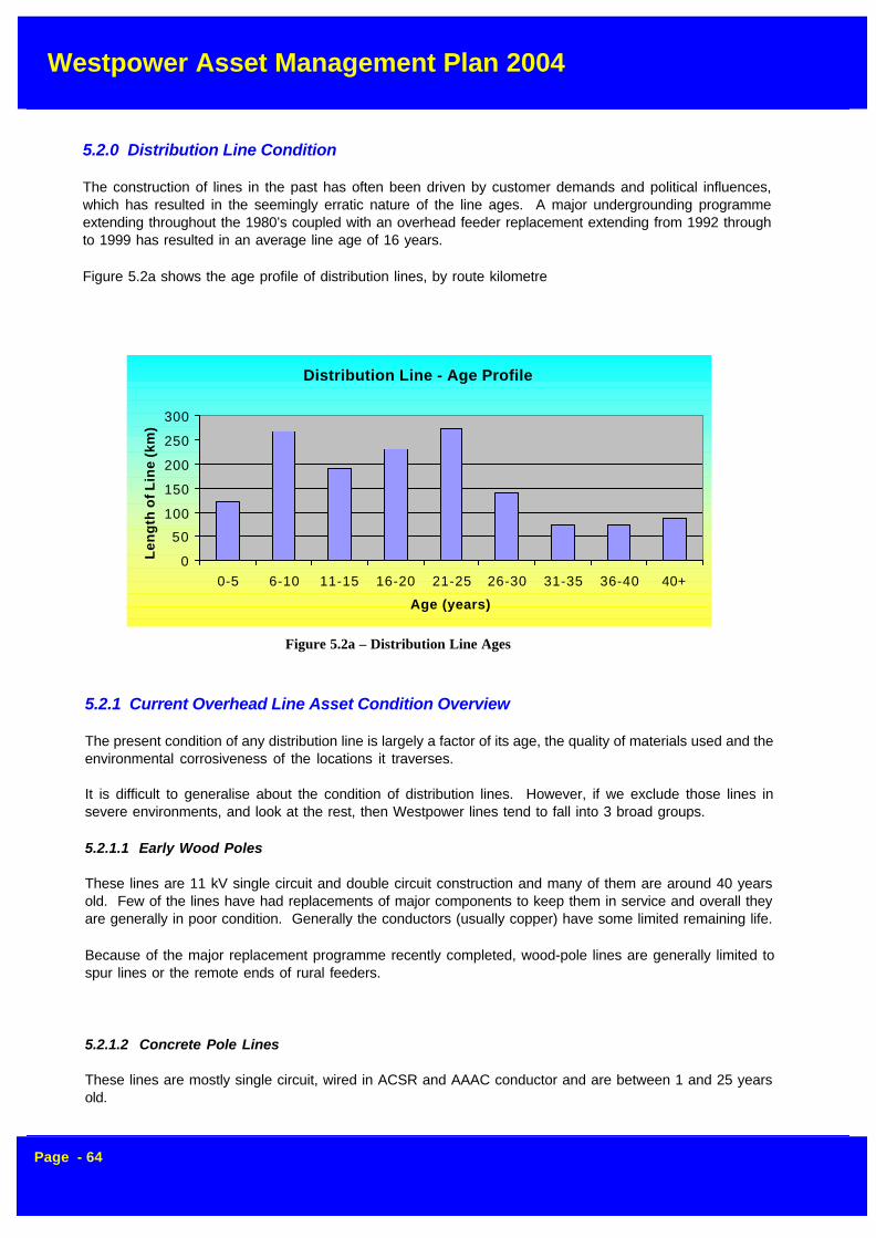
Westpower Asset Management Plan 2004
Page - 64
5.2.0 Distribution Line Condition
The construction of lines in the past has often been driven by customer demands and political influences,which has resulted in the seemingly erratic nature of the line ages. A major undergrounding programmeextending throughout the 1980’s coupled with an overhead feeder replacement extending from 1992 throughto 1999 has resulted in an average line age of 16 years.
Figure 5.2a shows the age profile of distribution lines, by route kilometre
5.2.1 Current Overhead Line Asset Condition Overview
The present condition of any distribution line is largely a factor of its age, the quality of materials used and theenvironmental corrosiveness of the locations it traverses.
It is difficult to generalise about the condition of distribution lines. However, if we exclude those lines insevere environments, and look at the rest, then Westpower lines tend to fall into 3 broad groups.
5.2.1.1 Early Wood Poles
These lines are 11 kV single circuit and double circuit construction and many of them are around 40 yearsold. Few of the lines have had replacements of major components to keep them in service and overall theyare generally in poor condition. Generally the conductors (usually copper) have some limited remaining life.
Because of the major replacement programme recently completed, wood-pole lines are generally limited tospur lines or the remote ends of rural feeders.
5.2.1.2 Concrete Pole Lines
These lines are mostly single circuit, wired in ACSR and AAAC conductor and are between 1 and 25 yearsold.
Figure 5.2a – Distribution Line Ages
Distribution Line - Age Profile
0
50
100
150
200
250
300
0-5 6-10 11-15 16-20 21-25 26-30 31-35 36-40 40+
Age (years)
Len
gth
of
Lin
e (k
m)
Westpower Asset Management Plan 2004
Page - 65
Two types of concrete poles were used
The earlier heavy-reinforced type manufactured by Westpower from the 1970’s until the early 1980’s. Theseare often referred to as “Hokitika” concrete poles because of where they were manufactured.
Pre-stressed concrete poles manufactured since the early 1980’s by a local bridge-beam builder underlicense to Stresscrete
The poles are structurally sound and have an expected life of sixty years.
There has been some concern regarding the long-term effect of the leaching out of cement below groundlevel in the “Hokitika” concrete poles in certain soil conditions, however the extent to which this affects thestructural integrity of the pole is still under investigation.
5.2.1.3 Treated Softwood Pole Lines
Construction of treated softwood pole lines began in 1992 for economic reasons, and continued through until1994 for main lines, when the cost differential between concrete and treated softwood poles underwent areversal. These lines are wired in ACSR or AAAC conductor.
5.2.2 Condition of Specific Line Components
5.2.2.1 Wood Poles
There are approximately 4000 distribution wood poles in service. An estimated 300 poles (7.5%) are as-sessed to be currently at replacement criteria, or to reach it within 5 years. Approximately another 300 areestimated as needing to be replaced between 2006 and 2011.
5.2.2.2 Conductors and Conductor Accessories
Copper conductor is fitted to the majority of older lines. Much of it is still in reasonable condition and canremain in service for a further 10-20 years. However vibration damage and corrosion has taken its toll.
Most of the conductor installed since the 1960’s have been conventional ACSR with greased steel core. Allconventional ACSR is prone to corrosion, especially where the line is subject to wind borne salt contamina-tion. Much of the early ACSR in exposed areas has been identified for careful inspection over the next 10years to determine what, if any, replacement programme should be undertaken.
5.2.2.3 Insulators and Insulator Fittings
There are a number of older porcelain discs now known to be unreliable due to inherent design faults plusin-service internal deterioration. In particular the relatively recent international discovery that older conven-tional porcelain can develop porosity during its service life (leading to punctures and mechanical separation)plus the known poor quality of much of the older porcelain insulation has provided added weight to thereplacement programme.
There are approximately 130,000 insulators in service. Of these, 2000 have currently been identified as duefor replacement over the next year due to inherent quality problems.
Replacement insulators are either glass or a polymer disc insulator with round pins.
Problems have also been noticed with EPDM polymer insulators showing signs of chalking and even crack-ing. An investigation is currently underway to assess the seriousness of the problem at 11 kV and the risk, ifany, that this apparent deterioration poses.
A condition assessment programme was begun to confirm the service life of a number of older NGK 33 kVporcelain pin-insulators used on the 33 kV sub-transmission line from Ngahere to Reefton.

Westpower Asset Management Plan 2004
Page - 66
Approximately 800 of these insulators were installed second-hand in the mid-1990’s as a cost saving mea-sure. Initially, they were installed in the 1960’s on the line to Ruatapu south of Hokitika, but then removedabout ten years later and placed in storage until being used on the line to Reefton
During commissioning of the line in 1999, two of these insulators failed resulting in spectacular earth faults. Afurther insulator failed in January 2000 following a severe lightning storm and these events, combined, raisedsome doubt as to the BIL and ongoing serviceability of this particular type of insulator. Subsequent analysisof a random sample of insulators confirmed that the general population of insulators is in good condition,however, and no further remedial action is required.
Corrosion problems have recently been identified with Dulmison pre-formed insulator ties used to attachaluminium conductors to insulators. When these are installed in coastal environments, severe corrosionoccurs under the neoprene cover used to cushion contact between the Helitie and the insulator, leading tocomplete failure of the unit. All new Helities are purchased to an updated standard that overcomes theseissues.
5.3 Low Voltage Reticulation Lines
Westpower currently owns 99 km of 400 V low voltage line assets, and this is not expected to changedramatically over the planning period. The largest single contribution to more LV lines is likely to come fromnew subdivisions, and in this case the reticulation will almost certainly be of underground construction be-cause of the requirements of local District Plans.
5.3.1 Current Asset Condition
Many of the factors described in section 5.2 – “Distribution Lines” - applies equally to their low voltagecounterparts.
In general, the age distribution of this asset is such that most of the asset is either very old or relatively new,with only a small proportion being constructed over the in between period.
The reason for this is that most of the LV construction was carried out at an early time in the town areas wherethe population density was the greatest. Over the years, this large population of assets aged together to thepoint where they reached the end of their service life. This, in turn, required a major refurbishment programme.
5.3.1.1 South Westland
The areas of Hokitika and South Westland have largely been rebuilt over the last 15 years. During this time,most of the urban reconstruction has been carried out using underground reticulation, which has a life of upto 50 years. Little further LV work is therefore planned in these areas.
5.3.1.1 Greymouth
In the Central Greymouth Area, some of the oldest lines were placed underground during the 1980’s. Thechange in focus during the late 1980’s to a more commercial footing led to the demise of undergroundingbecause of the substantially higher capital cost involved. From the early 1990’s on, remaining refurbishmentwork has been carried out with overhead reticulation.
The LV networks in the satellite towns of Blaketown, Cobden and Runanga have been reconstructed over-head in the last five years and are now in good condition.
5.3.1.2 Reefton
The Reefton area consists of mainly very old overhead LV lines which are in need of replacement. During the1980’s there was an undergrounding programme in place, which resulted in several streets, including themain business area, being undergrounded. In conjunction with Telecom, some areas will continue to be

Westpower Asset Management Plan 2004
Page - 67
undergrounded where cost sharing can be achieved.
About 30% of the LV reticulation has an age of 15 years or less, while the rest of the network would be over40 years old on average.
Several other small pockets of LV, such as Dobson and Blackball will also need attention during the planningperiod, and the required level of replacement for these areas will be identified during condition assessment ofthe asset. This will enable maintenance to be effectively targeted and provide a solid foundation for the moveto a Condition Based Maintenance (CBM) programme.
5.3.2 Condition of Specific LV Line Components
5.3.2.1 Underground Network
With the exception of a small number of old 400 V feeder cables in the Central Greymouth business district,most of the underground LV reticulation throughout Westpower’s area is less than 20 years old and in goodcondition.
The underground fittings used are also in good condition, mainly because of their age, however constantminor maintenance is still required to overcome problems due to corrosion or water ingress.
5.3.2.2 Wood Poles
Most of the LV wood poles are very old, predominantly hardwoods and range in condition from very poor togood. Their condition is best assessed through an objective testing programme.
5.3.2.3 Conductors and Conductor Accessories
All of the overhead lines constructed over the last twenty years consist mainly of PVC covered All AluminiumConductor (AAC) and are in generally good condition.
For a further period of about twenty years prior to this, PVC covered copper conductors were used, andthese also are in good condition. Where a LV line is replaced or refurbished, this type of conductor is reusedif it is in good condition and of an adequate cross-sectional area.
All lines over forty years of age that have not been refurbished during their life still use original braid coveredconductor. The major population of this type of conductor can be found in the Reefton Area where approxi-mately 40% of the remaining overhead LV conductor is braid. The condition of this conductor is very poorand could become a significant safety hazard if not attended to in the short term.
Other accessories demonstrate a condition commensurate with the age of the line and are replaced as partof the overall replacement programme.
5.4.0 Service Lines
Service lines on customer’s premises are owned and maintained by the individual customers.
Notwithstanding this, there are some service lines which are not of an acceptable standard due to insufficientclearance or other reasons. Westpower is responsible for bringing these up to standard before transferringthem to the customer.
Most service lines are either PVC covered copper or neutral screened copper and should give good servicefor many years. A few of the very old services are still of the braid variety, and these are replaced as a matterof course and at Westpower’s cost when a section of LV line is refurbished or replaced.

Westpower Asset Management Plan 2004
Page - 68
5.5.0 Zone Substations
5.5.1 General Condition
All of Westpower’s Zone Substations are less than 25 years old and demonstrate a condition commensuratewith their age. Two of the oldest substations at Whataroa and Kumara have since been substantially rebuiltover the last five years due to major enhancement projects and are in as new condition.
The enactment of new legislation in the areas of occupational health and safety and the Resource Manage-ment Act (1991) may require upgrading work at stations in the areas of oil interception facilities, fire protectionstation earthing and security fencing.
5.5.2 Transformers
Because of the proximity to a coastal environment, corrosion of tanks and fittings is a constant problem,which needs to be addressed by an ongoing painting programme.
The remaining population of transformers is now in a generally good condition, and no major maintenancewill be required throughout the planning period.
Dissolved Gas Analysis (DGA), performed annually for the last 3 years, has allowed Westpower to monitorthe internal condition of its power transformer population and demonstrate that in general there is little evi-dence of insulation ageing or deterioration.
In September 2000, a 1984 Tolley 5 MVA 33/11 kV transformer failed catastrophically after a series of heavyline faults. While the unit was successfully repaired, a failure mode analysis revealed a design fault wherebythe windings were insufficiently braced to withstand strong short-circuit forces. This particularly affected thetertiary winding. As a result of this, both the faulted unit and a sister unit purchased at the same time werefully refurbished with additional windings. Both units are now expected to give good service for at leastanother thirty years.
5.5.3 Switchgear
In general, all switchgear is in very good condition, partly due to Westpower’s very low fault duty. Vacuumreclosers in particular have very low maintenance requirements and are expected to remain in service for atleast the next twenty years.
At Kumara Substation, new Siemens SF6 66 kV circuit breakers were installed in 1997 as part of an upgradeproject and are in excellent condition.
Disconnectors are constantly subject to corrosion of bolts and operating linkages and need continual minormaintenance to keep them in good order.
5.5.4 Minimum Oil Switchgear
66 kV Minimum Oil Circuit Breakers were supplied during the late 1970’s. They are physically smaller thanBulk Oil Circuit Breakers, containing a much lower volume of oil, which leads to high electrical stresses andtheir performance is more susceptible to maintenance standards. Rigorous maintenance schedules need tobe strictly adhered to prevent failures from occurring.
Experience has shown that these units are susceptible to water ingress and need ongoing regular checks.Another problem encountered is seizing of the mechanism due to corrosion of exposed linkages. Apart fromthese points however, the units are in good condition.

Westpower Asset Management Plan 2004
Page - 69
5.5.5 Outdoor Reclosers
There are 47 outdoor reclosers in Westpower’s zone substations. This population has an age profile asshown in figure 5.5.5a. CIGRE studies indicate typical replacement ages of 40-45 years for circuit breakersrated at 80 kV and below.
5.5.6 Indoor Switchgear
Westpower indoor switchgear installations comprise 31 switch units in 4 locations. These comprise thefollowing types:-
- 4 SF6 reclosers- 24 Vacuum type reclosers- 3 Bulk oil reclosers
In early 1999, Westpower’s oldest 11 kV indoor switchgear at Kumara was upgraded with the retrofitting ofSF6 circuit breaker trucks. A life expectancy of thirty years is now expected from this equipment
A potential reliability problem was identified with the indoor bulk oil switchgear at Greymouth after a series ofcatastrophic failures elsewhere in New Zealand. Prior to this the SO-HI type equipment used has had achequered history, suffering from low internal clearances, resin insulation breakdown and poor immunity towater ingress. Furthermore, these indoor circuit breakers, while being relatively young at an average age of22 years, have been subjected to a heavy-duty cycle throughout their lives. Accordingly this switchboardwas be replaced with new vacuum circuit breakers during 2003.
The only other bulk oil switchgear in use is GEC type BVP equipment installed at Rapahoe in 1984 and itsgood condition coupled with low fault levels means that it will not require major attention within the planningperiod.
Age Distribution of Westpower Outdoor Switchgear (Zone Substations)
0%
5%
10%
15%
20%
25%
30%
35%
40%
45%
50%
0-5 6-10 11-15 16-20 21-25 26-30 31-35 35+
Age (Years)
% o
f To
tal
Figure 5.5.5a - Outdoor Switchgear Ages
Age Distribution of Westpower Indoor Switchgear (Zone Substations)
0%
10%
20%
30%
40%
50%
60%
0-5 6-10 11-15 16-20 21-25 26-30 31-35 35+
Age (Years)
% o
f To
tal
Figure 5.5.6a - Indoor Switchgear Ages

Westpower Asset Management Plan 2004
Page - 70
5.5.7 Disconnectors
Disconnectors are high voltage switches, which are used to disconnect sections of overhead line or otherprimary plant.
Over recent years there was a particular make of disconnector installed on the system with faulty insulators.These have all now been identified and taken out of service. The insulators have been replaced and thedisconnectors have been reused.
Some of the older Canterbury Engineering type DA7 disconnectors have also had problems with failinginsulators, but the occurrence of this type of failure has been infrequent enough not to require a specialreplacement programme.
New disconnectors generally give satisfactory service, but older designs are unreliable, and very old modelsare now becoming electrically inadequate. The only effective remedy is replacement of these units.
5.5.8 Buswork
Most buswork systems have been constructed in the last ten years and consist of concrete poles and tubularaluminium bus. These items require virtually no maintenance throughout their lives.
At the Greymouth Substation, a galvanised steel lattice structure is in place and is in good condition. Aconcern with this type of construction occurs when they reach an age where rusting develops which requirescontinuous maintenance to contain. A common problem is advanced deterioration of bolts, which graduallyreduces the overall strength of the structure. Severe structure corrosion is generally found at substationslocated near marine environments and where industrial works nearby give rise to a corrosive atmosphere.The proximity of Greymouth Substation to the coast means that a regular inspection programme will have tobe maintained to counter this.
Corrosion is also a problem in the metal parts of cap and pin insulators, which support buswork. On both postinsulators and string insulators severe rusting of the pins, leads to cracking of the porcelain causing theinsulator to fail. Also, the older type porcelain itself has been found to deteriorate. These are the sameproblems, which affect line insulators. In the case of strung buswork a failure could result in collapse of theconductor. Replacement with modern insulators and general upgrading of other hardware components isnecessary to reduce the risk of failures.
Cracking or spalling of concrete support structures and rusting of the reinforcing steel can be a problem thatrequires remedial action.
5.5.9 Instrument Transformers
Westpower has several outdoor oil filled instrument transformers, comprising current (excluding bushingtypes) and voltage units in the voltage range 11 kV to 66 kV. It is estimated that the average age is overfifteen years and only a small percentage is in excess of thirty years of age.
Generally they are in a good condition and require minimal maintenance. The cost of refurbishment andregular monitoring is such that in most instances it is more economic to replace the units if they fail.
The most common form of failure is due to stone damage by vandals, and this is handled as required.
5.5.10 Oil Containment
Oil containment facilities have been installed at most major Zone Substations within the last four years andare in excellent condition. The remaining installation at Ngahere is scheduled to have facilities installed inearly 2004.

Westpower Asset Management Plan 2004
Page - 71
5.5.11 Earthing Systems
Earthing systems in substations constructed within the last 15 years were designed to a high standard andmeet current industry guidelines.
All of the older Zone Substations that did not comply, including Greymouth, Kumara and Whataroa, under-went major upgrades of their earthing systems contemporaneous with other substation enhancement workcompleted within the last six years.
5.5.12 SCADA Remote Terminal Units
The existing Remote Terminal Units (RTU) installed at each remote site received a life extending upgrade inearly 1995, but are now technically obsolete, with spares and ongoing support no longer available. Completereplacement during the early stages of the planning period will be required. In conjunction with the digitalradio project, it is likely that local networked PLC’s will take over the role of RTU’s in future designs, andwhere possible, this will be included into the replacement programme.
5.5.13 Protection Relays
Most protection relays are in excellent condition and will only require minor inspection and servicing through-out the planning period.
A minor problem has been identified with sealed batteries in Cooper Form 4C and Form 3A recloser controlunits whereby the units succumb to a high rate of battery failure after three years of service. The interimsolution has been to carry out a cyclic battery replacement program of all recloser batteries after three years,but even this has proved ineffective in isolated circumstances. The net result has been some loss of discrimi-nation during fault events leading to wider power outages than would have been expected.
Accordingly, all critical protection relays at Zone Substations will be brought up to the current Westpowerstandard, which includes modern numerical Schweitzer Protection Relays, over the next three years.
Some replacement of protection relays due to obsolescence reasons is scheduled within the planning period.
5.5.14 Other Station Equipment
Battery banks at stations were originally fitted with automotive lead-acid type cells, which typically give a lifeof about 10 years. These have now been progressively replaced with sealed lead acid type batteries, whichhave a higher initial cost but give a far greater life (up to 20 years) and also have low maintenance require-ments.Notwithstanding the above, a number of unexplained internal high impedance faults on these sealed unitshas led Westpower to recently review its policy for future new or replacement banks. The current acceptedstandard has been to use Faure-X wet cells which have proven lives of at least 16 years, and are currently inuse in many Westpower substations. Recent problems with availability of these units, however has forcedWestpower to move back to the sealed units.
With the introduction of new safety regulations (SR-EI), it has been necessary to add safety authorisationrope and stands to station inventories.
5.6.0 Distribution Substations
Within Westpower’s network there are around 1600 distribution substations comprising single and threephase units ranging from 5 kVA to 1 MVA, in the voltage range of 33 kV to 11 kV.
The condition of these assets covers the whole range from being in need of immediate replacement to brand

Westpower Asset Management Plan 2004
Page - 72
new.All main line substation have been rebuilt over the last 20 years as part of Westpower’s refurbishmentprogramme and are generally in very good condition. There are still some very old substations on some spurlines however, which will need ongoing refurbishment throughout the planning period.
5.6.1 Dominion Drop Out (DDO) Fuses
As a standard design policy, a DDO fuse unit fuses all the distribution transformers, which are fed directlyfrom an overhead High Voltage Line.
Up until 1996, all fuse units were of the “E C Gough” type manufactured locally for many years. A majorreliability problem with these units caused Westpower to move to the AB Chance style of DDO. Howeverthese units were found not to pivot open properly when exposed to a corrosive environment for a period oftime. AM type dropouts imported from Austrailia are now being implemented with the Gough and Chanceunits being replaced as scheduled maintenance takes place on distribution substations.
5.6.2 Earthing Systems
The Electricity Regulations suggest that all substation-earthing systems should be brought up to a standardof 10 ohms. In Westpower’s situation, because of the very high soil resistivity that is often encountered, adesired earth resistance of 10 ohms is not practically achievable in all cases.
Nevertheless, the regulations do require that earthing systems be tested every five years, and Westpower isnow addressing this issue in earnest. To meet the requirements, a programme of earth testing has begunand will continue until the total substation population has been covered. After this time, a programme ofregular five-yearly tests will be instituted.
Based on experience, it is expected that during the testing phase, several substandard earthing installationswill be identified that are capable of being practically upgraded. A programme of upgrading these earthsystems using driven rods and extra copper conductor will follow on directly from the earth testing exercise.
5.7 Medium Voltage Switchgear
Most of Westpower’s MV switchgear is relatively modern and in good condition. However a recent series offaults on the Andelect Outdoor type Ring Main Unit has given cause to these units being replaced over thenext ten years using the new SF6 or Vacuum units. Westpower no longer use Series I oil insulated ABB RingMain Units to close onto expected faults.
Other exceptions to this are the large and diverse population of disconnectors, which will need to be man-aged on an asset-wide basis. See section 5.7.4 below.
5.7.1 Regulators
The oldest line regulator in service is at Cronadun, and is an old tap-changing unit purchased second-handfrom Transpower. This unit is reaching the end of its economic life and requires constant maintenance.Spare parts are hard to source and the unit is costly to maintain. A remaining life of at least five years shouldbe attainable however if the unit is carefully maintained.
A moving coil three phase regulator is installed at Longford Corner and is about 30 years old. The 1500 kVAunit is in good condition having experienced a relatively easy service life and will remain serviceable through-out the planning period.
A relatively modern set of Cooper SR32 single-phase 32-step regulators were commissioned at Hariharisubstation. This unit is expected to have at least twenty years of remaining life.

Westpower Asset Management Plan 2004
Page - 73
5.7.2 Circuit Breakers
Aged indoor bulk-oil circuit breakers have reached the end of their economic lives. These will be replacedwith fused switch units or modern equivalents over the next five years.
5.7.3 Pole Mounted Reclosers
All pole mounted circuit breakers are of the modern vacuum type and should give many years of acceptableservice.
5.7.4 Disconnectors
The most diverse asset type is that of disconnectors and these are constantly prone to corrosion damage.Most main line disconnectors have been replaced with new units during the recent feeder upgrade programme.
As older two-insulator models without “flicker” arcing horns are not suitable for use on main lines, a programmefor replacement has begun. Other three insulator models are also unsuitable on some lines because ofsystem loadings and an effort will be made to identify and replace these units within the next five years.
Some very old substations still use disconnectors in addition to the Dominion Drop Out (DDO) fuse unit as ameans of isolation for a fault on a DDO base. The intention is to replace these substation disconnectors withlive-line taps.
Other newer units do not have sufficient current breaking capacity because of individual line loadings and theonly solution in this case is to fit suitable load break heads.
5.8 SCADA, Communications and Protection
5.8.1 Supervisory Control and Data Acquisition (SCADA)
The SCADA Realflex Master Station underwent a mid-life hardware and software upgrade in March 1998followed by a more minor upgrade in 2001 and will not need further attention until 2005. At this time, a fullreplacement will likely be required, and a detailed investigation will need to be completed to determine suit-able technical requirements, and this has been allowed for in the current year.
Ongoing problems have been experienced with the historical collection module resulting in intermittent fail-ures of the data extraction utilities, however this is a systemic problem within the application software that themanufacturer is currently investigating. In the meantime a workaround has been devised.
The hardware is based on reputable brand name product and is proving very reliable.
Existing modems and changeover racks from the original SCADA system installed in 1982 are still in serviceand are still proving reliable.
5.8.2 Communication System
All VHF communication equipment is in excellent condition after a complete replacement programme thattook place in the early 90’s. Tait 2000 series equipment is now used throughout the network and rarely givestrouble.
The UHF network has equipment dating back to the mid 80’s, which, although still running well, is now gettingtoward the end of it’s economic life. Regular maintenance is required, however contractors are very familiarwith the equipment and a good stock of spares are held meaning that repair times are kept to a minimum.Nevertheless, the equipment is now technically obsolete, and unable to handle the automation and datacollection needs of the modern transmission substations that Westpower are now constructing. For this

Westpower Asset Management Plan 2004
Page - 74
reason, a digital radio backbone is currently being installed to support these new sites, with Stage 2 due forcompletion in October 2004. Over the following three years, this network will gradually be extended to coverall major Zone Substations, replacing the existing UHF radios.
The existing UHF analogue system in South Westland will be maintained for several years with spares wonfrom the upgrade project.
5.9 Distribution Transformers
The majority of transformer capacity is less than 30 years old, with a median age just over 20 years andnegligible capacity beyond 50 years old (3%). This coincides with the period of system development in the1960’s and early 1970’s.
Transformers are generally in good condition, although for some of the older painted transformers refurbish-ment and/or replacement is required rather than general maintenance.
A problem has been identified with deterioration of bushing gaskets on smaller units in the 6-10 year agebracket where these are installed near the coast. It appears that the surface leakage current attacks thegasket material, eventually leading to failure of the gasket and water ingress resulting in electrical failure ofthe transformer. To address this issue, a refurbishment programme has begun to replace at risk gaskets, andto install replacement bushings with a partial semi-conductive coating around the flange area.
5.10 Ripple Control
Westpower sold all of its ripple relays to the new incumbent retailer on 31 March 1999 along with exclusiveuse of channels existing at that time. The ripple injection plants were retained for the purpose of load controlas well as providing a load switching service to retailers under contract.
5.10.1 Ripple Injection Plants
All ripple injection plants are in good order as would be expected from their age profile. Nevertheless they arereaching the end of their useful life, with spare parts becoming increasingly difficult to obtain.
Because of their solid state construction, however, faults are unlikely to occur frequently.
It is, however, planned to replace one plant at Greymouth Substation with a new plant in the current year toprovide a source of spare parts for the existing population.

Westpower Asset Management Plan 2004
Page - 75
6.0 LIFECYCLE MANAGEMENT PLAN
6.1 Overview
This section outlines the lifecycle management plan required to maintain, enhance and develop the operatingcapability of the system. The programmes are outlined by asset type and, within this, according to area andthen by maintenance activity.
l Maintenance– servicing, inspections and testing– fault repairs– planned repairs and refurbishment (including replacement at the component level)
l Replacement– planned replacement programmes (at the asset level)
l Enhancement
l Development
6.1.1 Maintenance
Maintenance work is largely based on the condition of the assets, as outlined in section 5.The scope of work planned under each maintenance activity is quantified wherever possible to assist inreviewing Westpower’s achievement in future years. The estimated maintenance expenditure is projected inthis section and where relevant, the consequences of the proposed maintenance programmes are noted. Itshould be noted that analysis of maintenance strategies and programmes is an ongoing process and themost cost-effective means of maintaining the system is constantly under review. In some instances (e.g.pole replacement) further investigation and analysis is required to determine a suitable strategy.
The maintenance requirements are influenced by development projects, many of which, if they proceed, willlead to dismantling and decommissioning of assets which would otherwise require significant repairs.
Expenditure by Activity
0
2000
4000
6000
8000
10000
12000
14000
2005 2006 2007 2008 2009 2010 2011 2012 2013 2014
Year
$(00
0)
Faults Repairs Replacement Enhancement Inspection, Service & Testing Development

Westpower Asset Management Plan 2004
Page - 76
Maintenance Projects and Programmes ($'000)
2005 2006 2007 2008 2009 2010 2011 2012 2013 2014
Inspect Service & Test 2290 2352 2286 2111 2132 1948 1903 1888 1878 2078
Faults 293 293 293 293 293 293 293 293 293 293
Repairs 191 175 175 175 175 175 175 175 175 175
Total 2774 2820 2754 2579 2600 2416 2371 2356 2346 2546
The base-line planned maintenance expenditure projections assume, for consistency within this plan, thatdevelopment projects take place as projected in this section. It will be necessary to monitor closely thelikelihood of each project proceeding and additional remedial work will need to be programmed if certainprojects do not proceed or are significantly delayed.
(i) Repairs and Refurbishment
All line repairs are carried out to the requirements laid down in Westpower’s line maintenance standards.These are based on international practice combined with local knowledge and New Zealand legislative re-quirements.
6.1.2 Replacements
(i) Major Refurbishment’s
It is necessary to retain in service some older lines, which are in poor overall condition, and these linesrequire ongoing repairs and refurbishment.
Replacement Projects and Programmes ($'000)
2005 2006 2007 2008 2009 2010 2011 2012 2013 2014
Replacements 1477 1790 1610 887 668 120 100 50 50 50
(ii) Wood Poles and Crossarms
It is currently projected that approximately 250 poles would need changing over the next year in order tocope with defects arising on the existing wood pole lines.
Wood poles are being changed to concrete or treated softwood wherever possible, due to the increasinglypoor quality and increasing price of imported hardwoods from Australia. Local softwoods of the height andstrengths needed are beginning to become more expensive and may require ground line preservation tech-niques to extend their in service life.
The use of concrete poles, providing they can be sourced at the right price from the local supplier, can resultin significant savings in ongoing maintenance, increase line reliability, and increase line worker safety.
(iii) Conductors and Accessories
As a policy, all replacement Aluminium Conductor Steel Reinforced (ACSR) is being purchased with a greasedcore wire. Where corrosion resistance is critical in coastal areas, All Aluminium Alloy Conductor (AAAC) isused for its superior corrosion resistance properties
Major refurbishment on all line types is estimated to absorb only a small proportion of the total money pro-posed to be spent on line work in any year.

Westpower Asset Management Plan 2004
Page - 77
Development Projects and Programmes ($'000)
2005 2006 2007 2008 2009 2010 2011 2012 2013 2014
Development 6031 6541 2775 720 3465 565 565 1525 475 475
outages. These insulators have been proven to deteriorate rapidly after 10 years therefore a proactiveapproach is required to manage the risk of failure.
The replacement of such insulation is being afforded a high priority because of its immediate impact onsystem reliability, and because of the safety risk of line drops if the work is not attended to.
6.1.3 Enhancement
This activity outlines work which is planned to enhance the system. By this, it means that this increases tothe capacity of the system:
l provide more loadl enhance voltage regulationl improve security and reliability
Enhancement Projects and Programmes ($'000)
2004 2005 2006 2007 2008 2009 2010 2011 2012 2013
Enhancements 1300 905 780 500 180 60 60 0 0 0
It includes projects (at specific sites) and programmes of related work covering a number of sites.
6.1.4 Development
This section outlines the projects currently anticipated over the planning period. The nature of each projectis briefly described along with the reason why it appears to be required. The justifications for including eachof the projects in the plan are categorised as described in section 6, ie:
l specific customer requests (and commitment to incur project-related charges)l anticipated demand growthl to meet security planning guidelinesl economics (ie where the project produces overall cost savings)
The projects described in this section represent an indicative plan based on the best information currentlyavailable. There is currently no commitment by Westpower to undertake all or any of the specific projectslisted, nor should customer commitment be inferred from the inclusion of any project in this plan, exceptwhere they are described as being already committed. Further, it should be noted that more detailed inves-tigations will undoubtedly lead to changes in the scope of projects that do proceed. There may be consider-able scope for integrated transmission/distribution system planning to achieve the required results by some-what different means.
For larger conductors, with an aluminium cross-sectional area of over 95 mm2, Westpower policy is to useAAAC exclusively.
(iv) Insulators and Insulator Fittings
From the condition assessment programme it is estimated that there are approximately 300 33 kV EPDMstrain insulators requiring replacement over the next 5 years to avoid an unnecessary risk of line drop or fault
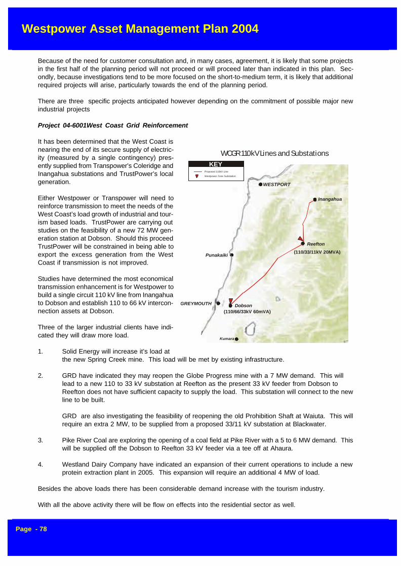
Westpower Asset Management Plan 2004
Page - 78
GREYMOUTH
Punakaiki
Dobson
Reefton
Inangahua
Kumara
WESTPORT
WCGR 110kV Lines and Substations
Proposed 110kV Line
Westpower Zone Substation
KEY
(110/33/11kV 20MVA)
(110/66/33kV 60mVA)
Because of the need for customer consultation and, in many cases, agreement, it is likely that some projectsin the first half of the planning period will not proceed or will proceed later than indicated in this plan. Sec-ondly, because investigations tend to be more focused on the short-to-medium term, it is likely that additionalrequired projects will arise, particularly towards the end of the planning period.
There are three specific projects anticipated however depending on the commitment of possible major newindustrial projects
Project 04-6001West Coast Grid Reinforcement
It has been determined that the West Coast isnearing the end of its secure supply of electric-ity (measured by a single contingency) pres-ently supplied from Transpower’s Coleridge andInangahua substations and TrustPower’s localgeneration.
Either Westpower or Transpower will need toreinforce transmission to meet the needs of theWest Coast’s load growth of industrial and tour-ism based loads. TrustPower are carrying outstudies on the feasibility of a new 72 MW gen-eration station at Dobson. Should this proceedTrustPower will be constrained in being able toexport the excess generation from the WestCoast if transmission is not improved.
Studies have determined the most economicaltransmission enhancement is for Westpower tobuild a single circuit 110 kV line from Inangahuato Dobson and establish 110 to 66 kV intercon-nection assets at Dobson.
Three of the larger industrial clients have indi-cated they will draw more load.
1. Solid Energy will increase it’s load atthe new Spring Creek mine. This load will be met by existing infrastructure.
2. GRD have indicated they may reopen the Globe Progress mine with a 7 MW demand. This willlead to a new 110 to 33 kV substation at Reefton as the present 33 kV feeder from Dobson toReefton does not have sufficient capacity to supply the load. This substation will connect to the newline to be built.
GRD are also investigating the feasibility of reopening the old Prohibition Shaft at Waiuta. This willrequire an extra 2 MW, to be supplied from a proposed 33/11 kV substation at Blackwater.
3. Pike River Coal are exploring the opening of a coal field at Pike River with a 5 to 6 MW demand. Thiswill be supplied off the Dobson to Reefton 33 kV feeder via a tee off at Ahaura.
4. Westland Dairy Company have indicated an expansion of their current operations to include a newprotein extraction plant in 2005. This expansion will require an additional 4 MW of load.
Besides the above loads there has been considerable demand increase with the tourism industry.
With all the above activity there will be flow on effects into the residential sector as well.

Westpower Asset Management Plan 2004
Page - 79
Project 04-6002 33 kV Supply to Industrial Mine Site Reefton
An enhanced 33 kV point of supply will be required from the grid at Reefton if GRD’s Globe Progress mineproceeds. A dedicated 33 kV feeder to the Globe Progress mine site will be required from the new 110/33/11kV Substation at Reefton.
33 kV Supply to Industrial Mine Site Pike River
Pike River Coal are exploring the opening of a coal field at Pike River with a 5 to 6 MW demand. This will besupplied off the Dobson to Reefton 33 kV feeder via a tee off at Ahaura.
A switching station will be required at Ahaura to allow for the Ngahere-Reefton section of the 33 kV feeder tobe split at Ahaura for a fault either side allowing supply to be continued to the Tee off. A third CB will connectthe spur to protect the feeder against faults on the spur.
6.2 Sub-Transmission Assets
As discussed in section 4, this asset class involves 33 kV and 66 kV power lines. The 66 kV assets areleased to Transpower and are a critical factor in the reliability of the national grid in the area. Accordingly, ahigher standard of care and maintenance is required.
6.2.1 Greymouth-Kumara 66 kV Line
The age of this asset is approaching mid-life requiring increased levels of inspection to manage risk andidentify early signs of deterioration.
6.2.1.1 Maintenance
(i) Routine Patrols and Inspections
An aerial and ground patrol of this line is performed annually. Fault patrols and fault repairs are carried out onan as required basis.
In addition to patrols, a detailed inspection of the entire line was carried out in 2003. During this inspectionevery aspect of the line was checked and recorded. The results will determine the extent of maintenance tobe carried out in the coming years.A full 100% ground line inspection, including ultrasonic pole density analysis was carried out in 1998 to give
Sub-Transmission Replacement Projects and Programmes ($'000)
2005 2006 2007 2008 2009 2010 2011 2012 2013 2014
Inspect Service & Test 413 404 389 274 375 287 242 217 217 217
Faults 10 10 10 10 10 10 10 10 10 10
Repairs 3 3 3 3 3 3 3 3 3 3
Replacements 45 45 45 45 20 20 20 0 0 0
Enhancements 0 115 110 60 60 0 0 0 0 0
Development 1000 1955 2100 105 700 0 0 350 0 0
Total 1471 2532 2657 497 1168 320 275 580 230 230
Westpower Asset Management Plan 2004
Page - 80
a baseline for future inspections.
Thermograph surveys are carried out on an annual basis to check for hot joints that could lead to later failure.These surveys are normally carried out at times of high load such as the winter period to increase thechances of detecting a marginal joint.
A tree trimming regime has been established due to the high growth experienced on the West Coast. Thisentails the sub-transmission lines being cleared of vegetation every two years so as to reduce the incidenceof accidental contact during storm conditions.
Project 05-1003: Greymouth - Kumara 66 kV Porcelain Strain Disc Replacement
As porcelain strain disc insulators have a limited life of around 25 years, the strain insulators on the Greymouth- Kumara 66 kV line have reached the end of their operational life. There are approximately 250 porcelainstrain insulators and associated hardware which will be replaced with glass strain insulators.
Project 05-1003: Greymouth - Kumara 66 kV Pole Replacement
The 03-04 Condition Assessment programme has revealed several poles and crossarms require replace-ment. Funds have been made available to replace any of these line components on an ongoing basis.
(ii) Faults
The level of fault occurrence is closely linked to condition of the asset and to external factors such as climaticconditions.
As far as climatic conditions are concerned, lightning and windstorms are usually the greatest sources ofproblems. This line has also at times developed transient earth faults during wet weather after long dryspells, possibly symptomatic of insulator contamination, but this is very rare.
It is very difficult to predict the number of faults from year to year due to climatic conditions. An estimate forfault work is provided based on information in the Job Costing and Service Maintenance Management sys-tems now used by the Asset Management Division.
(iii) Repairs and Refurbishment
All line repairs are carried out to the requirements laid down in Westpower line maintenance standards.These are based on international practice combined with local knowledge and legislative requirements.
A decision will be made on possible insulation replacement toward the middle of the planing period on quan-titative data has been gathered on the actual condition of the current insulators.
6.2.1.2 Enhancement
As a condition of the lease of this asset to Transpower, a circuit rating of 35 MVA must be maintained. Thecurrent Dog ACSR conductor has a summer time rating slightly below this value and re-conductoring may berequired in the future.Notwithstanding this, Transpower have accepted the current circuit rating until the full rating is required andit is very unlikely that load growth within the planning period will require the extra capacity.
Westpower Asset Management Plan 2004
Page - 81
6.2.2 Kumara-Kawhaka 66 kV Line
6.2.2.1 Maintenance
(i) Routine Patrols and Inspections
Fault patrols and fault repairs are carried out on an as required basis.
This line, although only 7 years old, will be included in the condition assessment programme , with 20 percentof the line thoroughly inspected annually. This will be in additional to a full ground and aerial patrol annually.
All joints used are of the compression type and were carefully tested by micro-ohmmeter during installation.As a result, thermograph surveys are unlikely to be of any benefit throughout the planning period and are notplanned for.
Project 05-1009: Fit Dogbone Vibration Dampers KUM-KHA 66 kV cct
To provide maximum protection to the conductor and associated fittings on the Kumara - Kawhaka cct,dogbone vibration dampers are to be fitted on spans exceeding 120m and meeting the design criteria for theinstallation of such dampers.
(ii) Faults
The level of fault occurrence is closely linked to condition of the asset and to external factors such as climaticconditions.
As far as climatic conditions are concerned, lightning is the most likely cause of problems. In the three yearsthat the line has been in service, it has only sustained one transient fault, and this was during a severelightning storm.
(iii) Repairs and Refurbishment
No repairs or refurbishment is planned for this line. Trees likely to cause a problem were cleared from theroute prior to construction and will not impact on the reliability of the line during the first half of the planningperiod
6.2.2.2 Enhancement
With the exception of the possible installation of enhanced lightning protection, should this prove necessary,no enhancement programmes are planned for this asset.
6.2.3 North Westland 33 kV Network
With the exception of the Dobson-Arnold Line, all of the lines in this area were constructed since 1984 givinga maximum age of only 16 years. The median age of this asset group is less than five years.
The age of the Dobson-Arnold line at around 60 years warrants higher levels of inspection and refurbishmentIn addressing this matter, a programme has been implemented to renew any pole identified as defective overa five year period.
6.2.3.1 Maintenance
(i) Routine Patrols and Inspections
Fault patrols and fault repairs are carried out on an as required basis.

Westpower Asset Management Plan 2004
Page - 82
I,S&T Sub-Transmission - Condition Assessment
Sub-Transmission Area 2005 2006 2007 2008 2009 2010 2011 2012 2013 2014
Dobson Arnold 33 kV Line Condition Assessment DOB1382 10 10 10 10 10 10 10 10 10 10
Dobson Rapahoe 33 kV Line Condition Assessment DOB1322 10 10 10 10 10 10 10 10 10 10
Dobson Reefton 33 kVLine Condition Assessment DOB1362 10 10 10 10 10 10 10 10 10 10
General Sub-Transmission Condition Assessment SYS 10 10 10 10 10 10 10 10 10 10
Greymouth Kumara 66kV Line Condition Assessment GYM-KUM 0 0 0 0 10 10 10 10 10 10
Harihari Franz 33 kVLine Condition Assessment HKK1012 10 10 10 10 10 10 10 10 10 10
Hokitika Harihari 66kV Line Condition Assessment HKK1012 22 0 0 0 0 10 10 10 10 10
Two Mile Hokitika 66kV Line Condition Assessment HKK1012 2 2 2 2 2 2 2 2 2 2
Total 74 52 52 52 62 72 72 72 72 72
Sub-Transmission Projects ($'000)
ID Act Project Description A r e a 2 0 0 5 2006 2007 2008 2 0 0 9 2 0 1 0 2011 2012 2013 2 0 1 4
- D Build New 33 kV Line to Pike River A H A 0 500 0 0 0 0 0 0 0 0
05-1001 I Dobson - Arnold 33 kV Line Maintenance DOB1342 11 0 0 0 0 0 0 0 0 0
- E Dobson Reefton 33 kV Line Insulator/Xarm Replacement DOB1362 0 15 1 0 10 10 0 0 0 0 0
05-1002 I Arnold Dobson 33 kV Line Pole Replacement DOB1382 28 25 2 5 25 25 25 25 0 0 0
- E GYM - KUM 66 kV cct Reconductor GYM-KUM 0 100 1 0 0 50 50 0 0 0 0 0
05-1003 I GYM - KUM Porcelain Strain Disc Replacement GYM-KUM 18 18 1 8 18 18 0 0 0 0 0
05-4001 RPL Pole Replacement GYM-KUM 66 kV cct GYM-KUM 20 20 2 0 20 20 20 20 0 0 0
05-1004 I Condemned pole replacement HKK-HHI HKK1012 30 30 3 0 30 30 30 30 3 0 30 30
- I Hendrix Line Pole Replacement HKK1012 0 30 3 0 30 30 30 0 0 0 0
05-1007 I Mount Hercules 33 kV Line Pole Replacement HKK1012 25 20 1 5 15 15 15 0 0 0 0
05-1006 I 33 kV Line Maintenance Franz Josef - Fox Glacier HKK1012 4 4 4 4 15 15 1 5 1 5 15 15
05-1005 I Fit new guys to structures on HHI-HKK cct HKK1012 15 15 1 5 0 0 0 0 0 0 0
05-1008 I HKK-HHI Porcelain Disc Replacement HKK1012 100 100 1 0 0 0 0 0 0 0 0 0
- D WCGR 110 kV Line Dobson Reefton IGH 0 105 2 1 0 0 105 0 0 0 0 0 0
05-6001 D WCGR 110 kV Line Ingangahua Reefton IGH372 900 900 0 0 0 0 0 0 0 0
05-1009 I Fi t Dogbone Vibrat ion Dampers KUM-KHA cct KUM-KAW 10 10 0 0 0 0 0 0 0 0
05-6002 D RGSP Macraes 33 kV Line - RFT - GLB RFT 100 450 0 0 0 0 0 0 0 0
- D SWGR Bui ld New 33 kV Line to Ross R S S 0 0 0 0 700 0 0 0 0 0
- D SWGR Build New 33 kV Line Ross - Kokatahi R S S 0 0 0 0 0 0 0 3 5 0 0 0
- I Paint subtransmission towers and comms towers SYS 0 0 0 0 80 0 0 0 0 0
05-1010 I Access Road Maintenance SYS 25 15 1 5 15 15 15 1 5 1 5 15 15
05-4002 RPL Replace All 33 kV EPDM Strain Insulators SYS 25 25 2 5 25 0 0 0 0 0 0
1311 2 3 8 2 2 5 0 7 347 1008 150 1 0 5 4 1 0 60 60
I ,S&T Sub-Transmission - Tree Trimming
Area 2005 2006 2007 2008 2009 2010 2011 2012 2013 2014
Dobson Arnold Line Tree Trimming DOB1382 5 1 0 1 0 1 0 1 0 1 0 1 0 10 10 10
Dobson Rapahoe Line Tree Trimming DOB1322 5 1 0 1 0 1 0 1 0 1 0 1 0 10 10 10
Dobson Reefton Line Tree Trimming DOB1362 5 1 0 1 0 1 0 1 0 1 0 1 0 10 10 10
Franz - Fox 33 kV Line Tree Trimming HKK1012 10 1 5 1 5 1 5 1 5 1 5 1 5 15 15 15
Greymouth Kumara 66kV Line Tree Trimming GYM-KUM 10 5 5 5 5 5 5 5 5 5
Harihari Wahapo Line Tree Trimming HKK1012 5 5 5 5 5 5 5 5 5 5
Hokitika Harihari 33kV Line Tree Trimming HKK1012 10 1 0 1 0 1 0 1 0 1 0 1 0 10 10 10
Kumara Kawhaka 66kV Tree Trimming KUM-KAW 10 1 0 1 0 1 0 1 0 1 0 1 0 10 10 10
Two Mile Road Hokitika 66kV Tree Trimming HKK1012 5 5 5 5 5 5 5 5 5 5
Wahapo Franz Line Tree Trimming HKK1012 8 5 5 5 5 5 5 5 5 5
Total 7 3 8 5 8 5 85 85 85 85 8 5 8 5 8 5
Projected Sub-Transmission Expenditure

Westpower Asset Management Plan 2004
Page - 83
In addition to patrols, a detailed inspection of this line is to be carried out on a rolling 5-year basis, covering20% of the route length per year. During the inspection every aspect of the line is checked. The aim is toidentify and document all components that do not meet Westpower standards.
The Dobson-Arnold line had a major inspection completed in 1997 which included an assessment of poleand hardware condition as well as an estimate of the pole safety factors in terms of bending moment. Allpoles were shown to be adequate at the time, however the age of the line means that annual general inspec-tions will continue to be carried out.
All pole hardware will be included in the inspections.
Project 05-1001: Dobson - Arnold 33 kV Line Maintenance
Recent condition assessment on the DOB-ALD 33 kV cct has discovered many insulators on the DobsonBack Road - Arnold Valley Road section of the line are in urgent need of replacement. In all, some 27 poleswill require re-insulation. In addition, the crossarms on pole 28577 require replacement. A contingency hasalso be allowed for the replacement of the wire rope guys (5x) on pole 28593 and pole step replacement on4 poles. This scope does not include poles replaced in the pole replacement project.
Project 05-1002: Dobson - Arnold 33 kV Line Pole Replacement
With some sections of the 33 kV line between the Dobson Substation and the Arnold Substation being part ofthe original line built in 1932, it is imperative poles which have reached replacement criteria be renewed. Acondition assessment programme on the line has indicated another eight poles will require replacement thisyear.
A regular annual thermograph survey will be carried out on these lines to monitor the condition of joints.
(ii) Faults
The level of fault occurrence is closely linked to condition of the asset and to external factors such as climaticconditions.
As far as climatic conditions are concerned, lightning and windstorms are usually the greatest sources ofproblems.
It is very difficult to predict the number of faults from year to year, due to climatic conditions. An estimate forfault work is provided based on information gathered in the Job Costing system and Service MaintenanceManagement system and Lightning Tracking software now used by the Asset Management Group.
(iii) Repairs and Refurbishment
All line repairs are carried out to the requirements laid down in Westpower line maintenance standards.These are based on international practice combined with local knowledge and legislative requirements.
With the above exceptions, no repair or refurbishment work is required on the concrete pole lines because ofthe low average age.
The Arnold-Dobson line will require individual pole replacement as well as re-conductoring and re-insulationwithin the next ten years unless a planned enhancement project proceeds.
(iv) Replacement
If the level of refurbishment on the Arnold-Dobson line becomes greater than 50% of the asset, complete linereplacement may be more cost effective. This will be reviewed toward the end of the planning period.

Westpower Asset Management Plan 2004
Page - 84
No replacement is foreseeable on the concrete pole lines.
6.2.3.2 Enhancement
Enhancement of any of the concrete pole sections is not envisaged unless driven by a major load increase.In this case, re-conductoring is the most likely activity.
The capacity of the existing Arnold-Dobson line is sufficient for the 3 MW Arnold Power Station to connectinto the grid, but has no spare capacity. Any significant increase in the injection demand at this site up toapproximately 5 MW will require the Arnold-Dobson line to be upgraded by re-conductoring and partial re-poling.
6.2.3.3 Development
Project 05-6002: New 33 kV Line from Reefton Sub to Macraes Mine Site at Globe Hill
With Macraes Mining receiving the green light to reopen an old hard rock gold mine at Globe Hill nearReefton, a processing plant will be built on this site, with an expected demand of around 5 MW. A new 12 kmIodine AAAC 33 kV line will be constructed from Reefton substation to Globe Hill, with a portion to be builtconjoint with an existing Westpower 11 kV line in the vicinity of Blacks Point. This is part of the Reefton GoldSupply Project (RGSP)
6.2.4 South Westland 33 kV Network
Much of the network in South Westland was constructed at the same time as that in North Westland and thesame comments apply to both areas.
South Westland does have some unique features, though, in the wood pole Mt Hercules section of theHarihari-Whataroa line and the fully insulated overhead cable routes around Lakes Wahapo and Mapourika,which require special management
The Mount Hercules line, with an age of 34 years, is to be refurbished over the next five years due to thedeterioration of poles and conductor. This line provides an essential link to South Westland, therefore de-manding priority within maintenance programmes.
With the addition of the Fox Glacier 33/11 kV substation on the network in 2003, the 11 kV line from FranzJosef to Fox Glacier was uprated to 33 kV. This line had major refurbishment carried at this time and shouldnot need any further major maintenance work for some time.
6.2.4.1 Maintenance
(i) Routine Patrols and Inspections
Fault patrols and fault repairs are carried out on an as required basis.
In addition to patrols, a detailed inspection of this line is to be carried out on a rolling 5-year basis, covering20% of the route length per year. During the inspection every aspect of the line is checked. The aim is toidentify and document all components that do not meet Westpower standards.
All pole hardware will be included in the inspections.
A regular annual thermograph survey will be carried out on these lines to monitor the condition of joints.
Westpower Asset Management Plan 2004
Page - 85
Project 05-1004: Condemned Pole Replacement HKK-HHI
This project will see approximately 10 poles which have been identified to have reached replacement criteria,be replaced on an on-going basis. This is a risk mitigation exercise and consideration will also be given toensure the design standards are appropriate for 66 kV construction.
Project 05-1005: Fit New Guys to Structures on the HHI-HKK cct
This project, a continuation of last years guy replacement project, will see a further 12 guys replaced. Theseare within 1 km of the coastline and have been awarded a higher priority. The replacements will include theguy wire, insulators and all associated hardware except the deadman and eyebolts, unless these compo-nents are deemed inadequate for the job.
Project 05-1006: 33 kV Line Maintenance Franz Josef - Fox GlacierThe Fox-Franz 33 kV line was given a large refurbishment in 2003/04 year, the criteria was to replace anycomponent that did not have five years life in it, unless a pole or component could be replaced live. Littlemaintenance should be required on the line itself for five years, however a contingency sum is available forsuch maintenance.
Project 05-1007: Mount Hercules 33 kV Line Pole Replacement
The continuation of the Mt Hercules 33 kV Line Pole Replacement project will see a further 7 poles bereplaced in the 04-05 financial year. This is a risk mitigation exercise and will be an ongoing project, whencomplete will see pole replacement across the entire Mt Hercules section of line.
Project 05-1008: HHI-HKK Porcelain Disc Replacement
Many of the 6300 suspension insulators on the HHI-HKK cct are porcelain pre 1970 type insulators. Toensure network security to the South Westland area these discs will need to be replaced with the glass typedisc insulator. This project see these discs replaced and will also include the insertion of an additional glassdisc where any 1990's era insulator strings are found to only have four disc per string.
(ii) Faults
The level of faults in this area is similar to that in North Westland. It may be reasonably argued however thatthe incidence of heavy rain, strong winds and lightning is slightly higher than in other areas.
(iii) Repairs and Refurbishment
All line repairs are carried out to the requirements laid down in Westpower line maintenance standards.These are based on international practice combined with local knowledge and legislative requirements.
(iv) Replacement
1 Project 04-4001: Replace all 33 kV EPDM Strain Insulators.
The rapid deterioration of EPDM type strain insulators has forced the replacement of this type of insulatorsystem wide. Glass Strain type insulator strings shall used as replacement discs. This is an on-goingproject, with investigations being completed in the 2002-03 financial year.
6.2.4.2 Enhancement
As the load in South Westland rises, it will be necessary to provide more capacity between Harihari andWhataroa to meet the substantially increased load being supplied south of Whataroa substation. The maxi-mum acceptable load on this circuit without incurring excessive volt drop is 2.0 MVA. This given little marginwhen supplying the present tourist season peak load of 1.6 MVA.

Westpower Asset Management Plan 2004
Page - 86
As the load continues to grow in South Westland, a decision will need to be made on when to increase thesub-transmission voltage from 33 kV to 66 kV. The line from Arahura to Harihari was originally built as a 66kV line by the New Zealand Electricity Department in the mid-1960’s, and was then leased to Westpower foroperation at 33 kV in 1993 before finally being sold to Westpower in 2001. It is therefore relatively easy to re-liven the line at 66 kV in the future.
Of course, this will also mean that Zone Substations at Ross and Waitaha need to be upgraded to run at 66kV and a new 66/33 kV substation be established at Harihari.
Based on current load growth projections, it is likely that the conversion will need to take place around 2007.In the meantime, additional reactive support will be required from 2003, followed by the installation of 33 kVregulators at Harihari in 2004 to overcome unacceptable voltage regulation, particularly when Wahapo PowerStation is not running. The reactive support will be in the form of a mixture of fixed and switched capacitorbanks.
6.2.4.3 Development
No major development work is planned on this network within the planning period. Any development thatdoes come about will likely be driven by customer requirements.
6.2.45 Other 33 kV Network ProjectsProject 05-1010: Access road maintenance
To assist in the swift restoration of faults in the area it is imperative access to lines are kept open and clear.Westpower administers many access roads, particularly roads adjacent to sub-transmission lines.
Project 05-4002: Replace all 33 kV EPDM strain insulators
The rapid deterioration of the EPDM type strain insulators has forced the replacement of this type of insulatorsystem wide. Glass strain type insulator strings shall be used as replacement discs. This is an on goingproject until all 33 kV EPDM strain insulators are replaced. This financial year will see the "Dobson-StillwaterTriangle" area targeted for replacement.
6.3 Distribution Assets
These assets comprise the majority of Westpower’s network by distance and value. As a logical result ofthis, the asset type also accounts for the greatest share of maintenance and enhancement expenditure.
Distribution Projects and Programmes ($'000)
2005 2006 2007 2008 2009 2010 2011 2012 2013 2014
Inspect, Service & Test 892 961 924 914 909 909 909 909 909 909
Faults 166 166 166 166 166 166 166 166 166 166
Repairs 71 55 55 55 55 55 55 55 55 55
Replacements 804 975 762 487 343 20 0 0 0 0
Enhancement 615 155 155 90 90 30 30 0 0 0
Development 545 336 0 50 0 0 0 0 0 0
Total 3093 2648 2062 1762 1563 1180 1160 1130 1130 1130

Westpower Asset Management Plan 2004
Page - 87
Inpection, Service and Testing - Condition Assessment ($'000 )
Area 2005 2006 2007 2008 2009 2010 2011 2012 2013 2014
Arnold Feeder 3 Condition Assessment ALD3 0.8 0.8 0.8 0.8 0.8 0.8 0.8 0.8 0.8 0.8
Arnold Feeder 4 Condition Assessment ALD4 4.5 4.5 4.5 4.5 4.5 4.5 4.5 4.5 4.5 4.5
Dillmans Feeder 4 Condition Assessment DIL4 1.5 1.5 1.5 1.5 1.5 1.5 1.5 1.5 1.5 1.5
Dobson Feeder 1 Condition Assessment DOB1 1.5 1.5 1.5 1.5 1.5 1.5 1.5 1.5 1.5 1.5
Dobson Feeder 3 Condition Assessment DOB3 1.5 1.5 1.5 1.5 1.5 1.5 1.5 1.5 1.5 1.5
Franz Feeder 1 Condition Assessment FRZ1 2.3 2.3 2.3 2.3 2.3 2.3 2.3 2.3 2.3 2.3
Franz Feeder 3 Condition Assessment FRZ3 0.8 0.8 0.8 0.8 0.8 0.8 0.8 0.8 0.8 0.8
Greymouth Feeder 6 Condition Assessment GYM11 1.5 1.5 1.5 1.5 1.5 1.5 1.5 1.5 1.5 1.5
Greymouth Feeder 7 Condition Assessment GYM12 0.8 0.8 0.8 0.8 0.8 0.8 0.8 0.8 0.8 0.8
Greymouth Feeder 11 Condition Assessment GYM13 0.8 0.8 0.8 0.8 0.8 0.8 0.8 0.8 0.8 0.8
Greymouth Feeder 12 Condition Assessment GYM6 0.8 0.8 0.8 0.8 0.8 0.8 0.8 0.8 0.8 0.8
Greymouth Feeder 13 Condition Assessment GYM8 1.5 1.5 1.5 1.5 1.5 1.5 1.5 1.5 1.5 1.5
Harihari Feeder 1 Condition Assessment HHI1 0.8 0.8 0.8 0.8 0.8 0.8 0.8 0.8 0.8 0.8
Harihari Feeder 3 Condition Assessment HHI3 0.8 0.8 0.8 0.8 0.8 0.8 0.8 0.8 0.8 0.8
Hokitika Feeder 10 Condition Assessment HKK10 7.5 7.5 7.5 7.5 7.5 7.5 7.5 7.5 7.5 7.5
Hokitika Feeder 12 Condition Assessment HKK12 0.8 0.8 0.8 0.8 0.8 0.8 0.8 0.8 0.8 0.8
Hokitika Feeder 4 Condition Assessment HKK4 2.3 2.3 2.3 2.3 2.3 2.3 2.3 2.3 2.3 2.3
Kumara Feeder 1 Condition Assessment KUM1 1.5 1.5 1.5 1.5 1.5 1.5 1.5 1.5 1.5 1.5
Kumara Feeder 2 Condition Assessment KUM2 0.8 0.8 0.8 0.8 0.8 0.8 0.8 0.8 0.8 0.8
Ngahere Feeder 1 Condition Assessment NGA1 1.5 1.5 1.5 1.5 1.5 1.5 1.5 1.5 1.5 1.5
Ngahere Feeder 3 Condition Assessment NGA3 4.5 4.5 4.5 4.5 4.5 4.5 4.5 4.5 4.5 4.5
Otira Feeder 1062 Condition Assessment OTI1062 0.8 0.8 0.8 0.8 0.8 0.8 0.8 0.8 0.8 0.8
Rapahoe Feeder 1 Condition Assessment RAP1 1.5 1.5 1.5 1.5 1.5 1.5 1.5 1.5 1.5 1.5
Rapahoe Feeder 3 Condition Assessment RAP3 1.5 1.5 1.5 1.5 1.5 1.5 1.5 1.5 1.5 1.5
Reefton Feeder 1 Condition Assessment RFT1 2.3 2.3 2.3 2.3 2.3 2.3 2.3 2.3 2.3 2.3
Reefton Feeder 3 Condition Assessment RFT3 2.3 2.3 2.3 2.3 2.3 2.3 2.3 2.3 2.3 2.3
Ross Feeder 1 Condition Assessment ROS1 0.3 0.3 0.3 0.3 0.3 0.3 0.3 0.3 0.3 0.3
Ross Feeder 3 Condition Assessment ROS3 0.8 0.8 0.8 0.8 0.8 0.8 0.8 0.8 0.8 0.8
Wahapo Feeder 1 Condition Assessment WAH1 0.8 0.8 0.8 0.8 0.8 0.8 0.8 0.8 0.8 0.8
Waitaha Feeder 1 Condition Assessment WTH1 0.8 0.8 0.8 0.8 0.8 0.8 0.8 0.8 0.8 0.8
Whataroa Feeder 1 Condition Assessment WAT1 1.5 1.5 1.5 1.5 1.5 1.5 1.5 1.5 1.5 1.5
Total 51.4 51.4 51.4 51.4 51.4 51.4 51.4 51.4 51.4 51.4
6.3.1 Reefton Area
The main feeders in the Reefton Area have been completely replaced over the last ten years with the excep-tion of Reefton Township itself Inangahua to the Iron Bridge and the line to Garvey’s Creek.
6.3.1.1 Maintenance
(i) Routine Patrols and Inspections
The 2004-05 financial year will see the continuation of the condition assessment programme. Each line(feeder) is to be inspected on a rolling 5-year basis, covering 20% of the route length per year. During theinspection every aspect of the line is checked.
Fault patrols and fault repairs are carried out on an as required basis.

Westpower Asset Management Plan 2004
Page - 88
(i) Faults
Faults in the Reefton area, like many others, are dependent on climatic conditions.
Trees have been a major problem in this area, particularly on the Garvey’s Creek line, which runs throughheavily forested areas including a pine plantation. A major tree-trimming project in 1998 coupled with har-vesting of mature pine trees in the pine plantation has reduced this risk, but it is still considerable.
A fault base will be maintained in the Reefton area contracted to ElectroNet Services for the foreseeablefuture to minimise the repair times that are involved during outage.
(ii) Repairs and Refurbishment
The condition assessment project discussed previously is likely to highlight several components requiringreplacement on those lines. This will be handled by a live-line refurbishment programme including individualpole, crossarm, insulator and conductor replacement where required.
Project 05-1102: 11 kV pole replacement, Upper Buller Gorge
Pole replacement through the Upper Buller Gorge is to take place on a priority basis. Eight poles have beenidentified as requiring replacement this year with a contingency sum to allow for another 5 poles to bereplaced.
(iii) Replacement
Project 05-4125:11 kV line replacement, Snowy River, Hukarere
Built in 1962, the section of line traversing Mossy Creek Road from Snowy River Road to Lemons property(S211) is beyond it's serviceable life. This project will eventually include the replacement of all sub-standardhardwood poles and associated fittings with 4-5 poles replaced per year. This financial year will see the first5 poles replaced.
Project 05-4126: 11 kV line replacement, Blackwater
Many poles on the Blackwater 11 kV line require replacement. The condition assessment programme willdetermine which of these poles will take a priority, with a contingency sum allowed for the replacement of 4poles per year, for the next 5 years.
Project 05-4127: 11 kV pole replacement, Thompsons Road, Mawheraiti
A recent inspection revealed several hardwood poles at the State Highway end of Thompsons Road, Mawheraitiwere in need of replacement. Six poles from the main line takeoff to, and including termination pole 09945,were found to have rotted at ground level and needed urgent attention. Disconnector HM2 shall be replacedwith gang type dropout fuses. These fuses will be funded from the Gang Type Fuse installation project.
Project 05-4128: 11 kV pole replacement, Aharua
Recent condition assessment of the 11 kV in the Aharua township has revealed some hardwood poles are inneed of replacement. In all, 5 poles require replacement due to rot or general deterioration. The poles to bechanged out this year will be from and including 05349 (HR19) along Clifton St to and including 05352 on thecorner of Clifton and Manuka St. 180 m Squirrel ACSR conductor shall be strung from 05348 to 05352. Inaddition, pole 05325 in Grey St shall also be replaced.

Westpower Asset Management Plan 2004
Page - 89
6.3.1.2 Enhancement
Project 05-5101: 11 kV line upgrade, Blackwater - Waiuta
Oceana Gold plan to reopen the Waiuta Mine and need a 2 MW supply for pumping and mining operations.Using existing poles where possible, a new 11 kV Iodine AAAC line will be built from the new BlackwaterSubstation to the mine shaft to supply this load. The existing line is constructed with very light Mullet conduc-tor and cannot handle the load from either a voltage regulation or thermal load perspective.
Project 05-5107: Upgrade Copper conductor,Reefton - Soldiers Rd to HM10
The existing 7/.064 conductor between the Inangahua River crossing south of Reefton to HM10 near Sol-diers Road is too light for the current load. This 520 m section of line shall be replaced with Ferret ACSR andwill remove a 'weak point' from the network. The two remaining hardwood poles on this section of line (09560& 09561) shall also be replaced.
Distribution Tree Trimming ($'000)
Area 2005 2006 2007 2008 2009 2010 2011 2012 2013 2014
Arnold Feeder 3 Tree Trimming ALD3 5 5 5 5 5 5 5 5 5 5
Arnold Feeder 4 Tree Trimming ALD4 12 15 15 15 15 15 15 15 15 15
Dillmans Feeder 4 Tree Trimming DIL4 5 10 10 10 10 10 10 10 10 10
Dobson Feeder 1 Tree trimming DOB1 5 10 10 10 10 10 10 10 10 10
Dobson Feeder 3 Tree Trimming DOB3 5 5 5 5 5 5 5 5 5 5
Fox Glacier Feeder 1 Tree Trimming FOX1 10 10 10 10 10 10 10 10 10 10
Franz Feeder 1 Tree Trimming FRZ1 2 2 2 2 2 2 2 2 2 2
Franz Feeder 3 Tree Trimming FRZ3 5 10 10 10 10 10 10 10 10 10
Greymouth Feeder 11 Tree Trimming GYM11 3 3 3 3 3 3 3 3 3 3
Greymouth Feeder 12 Tree Trimming GYM12 5 5 5 5 5 5 5 5 5 5
Greymouth Feeder 13 Tree Trimming GYM13 5 10 10 10 10 10 10 10 10 10
Greymouth Feeder 6 Tree Trimming GYM6 5 10 10 10 10 10 10 10 10 10
Greymouth Feeder 8 Tree Trimming GYM8 5 5 5 5 5 5 5 5 5 5
Harihari Feeder 1 Tree Trimming HHI1 5 10 10 10 10 10 10 10 10 10
Harihari Feeder 3 Tree Trimming HHI3 5 5 5 5 5 5 5 5 5 5
Hokitika Feeder 10 Tree Trimming HKK10 5 10 10 10 10 10 10 10 10 10
Hokitika Feeder 12 Tree Trimming HKK12 10 15 15 15 15 15 15 15 15 15
Hokitika Feeder 4 Tree Trimming HKK4 5 5 5 5 5 5 5 5 5 5
Kumara Feeder 1 Tree Trimming KUM1 5 5 5 5 5 5 5 5 5 5
Kumara Feeder 2 Tree Trimming KUM2 1 1 1 1 1 1 1 1 1 1
Ngahere Feeder 1 Tree Trimming NGA1 8 10 10 10 10 10 10 10 10 10
Ngahere Feeder 3 Tree Trimming NGA3 5 10 10 10 10 10 10 10 10 10
Otira Feeder 1062 Tree Trimming OTI1062 5 5 5 5 5 5 5 5 5 5
Rapahoe Feeder 1 Tree Trimming RAP1 5 10 10 10 10 10 10 10 10 10
Rapahoe Feeder 3 Tree Trimming RAP3 5 10 10 10 10 10 10 10 10 10
Reefton Feeder 1 Tree Trimming RFT1 5 10 10 10 10 10 10 10 10 10
Reefton Feeder 3 Tree Trimming RFT3 5 10 10 10 10 10 10 10 10 10
Ross Feeder 1 Tree Trimming ROS1 1 1 1 1 1 1 1 1 1 1
Ross Feeder 3 Tree Trimming ROS3 5 5 5 5 5 5 5 5 5 5
Wahapo Feeder 1 Tree Trimming WAH1 5 5 5 5 5 5 5 5 5 5
Waitaha Feeder 1 Tree Trimming WTH1 5 5 5 5 5 5 5 5 5 5
Whataroa Feeder 1 Tree Trimming WAT1 5 10 10 10 10 10 10 10 10 10
Total 167 242 242 242 242 242 242 242 242 242
Westpower Asset Management Plan 2004
Page - 90
Project 05-5108: Upgrade 11 kV line, Reefton Ring
Another progressive job is the replacement of the 11 kV ring in Reefton. Poles from Lucas Street through toBuller Road are to be replaced, along with 450 meters of Iodine AAAC strung to replace the existing MulletACSR conductor. This is to further strengthen the line in anticipation of greater load in the area.
6.3.1.3 Development
Any new development work in the Reefton area will only be required if major new loads materialise.
6.3.2 Greymouth Area
This is the largest area within Westpower’s district and also involves the greatest diversity of line types andcondition.
6.3.2.1 Maintenance
(i) Routine Patrols and Inspections
The 2004-05 financial year will see the continuation of the condition assessment programme. Each line(feeder) is to be inspected on a rolling 5-year basis, covering 20% of the route length per year. During theinspection every aspect of the line is checked.
As for the Reefton area, it is expected that this will form the basis of a repair programme involving individualcomponent replacements throughout the planning period.
Fault patrols and fault repairs are carried out on an as required basis.
A regular annual thermograph survey will be carried out on selected high-density lines to monitor the condi-tion of joints.
(ii) Faults
Faults in the Greymouth area, are normally caused by wind and lightning
Trees have been a major problem in this area, and a regular tree-trimming programme carried out at a feederlevel will contain this.
The base for Westpower’s contractor ElectroNet Services is located in Greymouth, and this will continue toserve as a fault base for the area.
(iii) Repairs and Refurbishment
Previous inspection projects have highlighted several components requiring replacement on the NelsonCreek, Blackball, Haupiri and Kopara lines. This will be handled, where possible, by a live-line refurbishmentprogramme including individual pole, crossarm, insulator and conductor replacement where required.
An ongoing programme to replace very old service poles will continue as required.
Project 05-1103: Relocate 11 kV fuses on spurs to main line takeoffs Greymouth area
Many spurs are not protected off main lines. Permanent faults down these spurs cost SAIDI's to a main line.Installing fuses at strategic locations will aid fault removal. 8 new three way gang type fuse units will beinstalled. In addition 13 fuse units will require relocation out to the main line from their existing positions atsub sites.

Westpower Asset Management Plan 2004
Page - 91
(iv) Replacement
With several lines within the Greymouth area and surrounding districts reaching the end of their economiclives, projects have been initiated to replace these lines. Some projects involve the replacement of conduc-tor and poles, while others will see only the poles being replaced.
Project 05-4101: 11 kV line replacement, Blair Block
The 2004-05 financial year will see the continuation of the Blair Block 11 kV line replacement programme.The line shall be upgraded from the final pole of the 03-04 project to the end of the line. All existing hardwoodpoles along with associated fittings and conductor are to be replaced.
Project 05-4102: 11 kV line replacement, Perkins - Haupiri
The 11 kV line from DH2, near the Perkins property, to Haupiri has a mix of old line, dating back to 1964, andrecently built sections. This project, which will eventually see the complete line upgraded (75 poles), is tocontinue with the section from DH26 to pole 04715 being replaced this financial year. The existing Ferretconductor shall remain.
Project 05-4103: 11 kV line replacement, Wainihinihi - Taipo River
Continuing from last years Turiwhate - Rocky Point project, this financial year will see sub-standard poleschanged out between the Big Wainihinihi River and the Taipo River. Over a two year period, approximately33 hardwood poles will be replaced, with the existing Ferret conductor remaining.
Project 04-4104: 11 kV line replacement, Inchbonnie
The 11 kV line from XD21, at the corner of the Inchbonnie-Rotomanu Road and Kumara - Inchbonnie Roadhas approximately 45 sub standard wooden poles. Recent development in this area, particularly the upsurgein the dairy industry, has seen this line fast tracked for replacement. The upgrade will be completed in stagesover the next two years. The 2004-05 financial year will see the section of line from the final pole changed outlast year (02394) to S175, including the spurline to S174 replaced. This will include the replacement ofapproximatley 23 wood poles and 1500 m of Mullet conductor.
Project 05-4105: 11 kV line replacement, , SH7, Stillwater
The replacement of six 11 kV hardwood poles at Stillwater will complete the wooden pole changeout in theimmediate area. These poles have shown signs of rapid deterioration in recent years and have reachedreplacement criteria. Staged over 2 years, the final year will see new Iodine AAAC replace the existing 19/.064 copper conductor from DH4 to DH32.
Project 05-4106: 11 kV line replacement, , Dobson Straight
Recent years have seen the 11 kV line from Greymouth to Dobson progressivley upgraded. The 04-05financial year will see this project continue with the substandard hardwood poles replaced from the end oflast years upgrade at pole 01375 to pole 01367, the takeoff to Nolans. Pole placement can become difficultin this area with the need to use culverts in the drain adjacent to the line increasing costs. The existingconductor shall remain until the 05-06 financial year.
Project 05-4107: 11 kV line replacement, Golf Links Road, Kaiata
The 11 kV pole replacement project at Golf Links Road, Kaiata has been deferred in recent years. The stateof the line has deteriorated to the point replacement has now become a high priority. The project includes thereplacement of eight hardwood poles along with associated fittings. The existing 7/.064 conductor shall bereplaced with Squirrel ACSR.
Project 05-4109: 11 kV line replacement, Murray St to Herbert Street
The majority of the line between the Greymouth substation and RA5 in Herbert Street has been upgraded inrecent years. One remaining section however is in need of replacement. The 11 kV hardwood line alongMurray Street to RA5 requires 8 hardwood poles to be replaced, with the existing conductor remaining. This

Westpower Asset Management Plan 2004
Page - 92
Distribution Projects ($'000)
ID Act Description Area 2005 2006 2007 2008 2009 2010 2011 2012 2013 2014
05-4101 RPL 11 kV Line Replacement, Blair Block ALD3 20 20 0 0 0 0 0 0 0 0
06-6101 D Install Moana 11 kV Ring ALD4 45 0 0 0 0 0 0 0 0 0
- E Iveagh Bay Underground ALD4 0 0 0 0 0 0 0 0 0 0
- RPL Christian Community - Kopara - Coates ALD4 0 48 48 48 0 0 0 0 0 0
- RPL Kopara Birchfield to Gloriavale ALD4 0 20 20 20 0 0 0 0 0 0
05-4102 RPL 11 kV Line Replacement, Perkins - Haupiri ALD4 37 0 0 0 0 0 0 0 0 0
- RPL 11 kV Pole Replacement, Moana-Ruru ALD4 0 35 0 0 0 0 0 0 0 0
05-5101 E 11 kV Line Replacement, Blackwater - Waiuta BWR 350 0 0 0 0 0 0 0 0 0
- RPL 11 kV Line Replacement Duffers - Wainihinihi DIL4 0 0 30 30 30 0 0 0 0 0
05-4104 RPL 11 kV Line Replacement, Inchbonnie DIL4 65 65 0 0 0 0 0 0 0 0
04-4103 RPL 11 kV Pole Replacement, Wainihinihi - Taipo River DIL4 40 40 0 0 0 0 0 0 0 0
05-4105 RPL 11 kV Line Replacement, SH 7, Stillwater DOB1 20 20 0 0 0 0 0 0 0 0
- RPL 11 kV Pole Replacement, Mt Sewell DOB1 0 15 15 15 15 15 0 0 0 0
05-4106 RPL 11 kV Line Replacement Dobson Straight DOB3 20 28 28 28 0 0 0 0 0 0
05-4107 RPL 11 kV Line Replacement, Golf Links Rd Kaiata DOB3 35 0 0 0 0 0 0 0 0 0
05-5102 E Fox Glacier 11 kV ring FOX1 40 0 0 0 0 0 0 0 0 0
05-4108 RPL 11 kV Line Replacement, Cook Flat Road - Fox Power Station FOX1 15 0 0 0 0 0 0 0 0 0
05-4136 RPR Retension conductor Paringa River to Lake Paringa FOX1 16 0 0 0 0 0 0 0 0 0
05-5103 E Replace Mullet Conductor with Mink - Franz Sub to Gibb Subdivision FRZ3 16 0 0 0 0 0 0 0 0 0
05-5104 E Upgrade Greens Rd Franz from 1 phase to 3 phase FRZ3 6 0 0 0 0 0 0 0 0 0
05-1101 I Fit pole caps to softwood poles, Waiho Flat Road FRZ3 5.5 0 0 0 0 0 0 0 0 0
- RPL Replace 11 kV conductor North of Franz Sub to Molloy's FRZ3 0 0 40 0 0 0 0 0 0 0
05-6102 D Globe Hill - Build Distribution Lines for Mine Site GLOBE 500 0 0 0 0 0 0 0 0 0
- D New feeder cable, Grey Hospital to New World GYM11 0 66 0 0 0 0 0 0 0 0
05-4109 RPL 11 kV Line Replacement, Murray St to Herbert Street GYM12 4 10 10 0 0 0 0 0 0 0
- D Alexander St -alternative feed to Greymouth CBD GYM13 0 70 0 0 0 0 0 0 0 0
05-4110 RPL Replace 11 kV underground cables, Greymouth CBD GYM7 5 20 20 20 0 0 0 0 0 0
- D Install 11 kV Alternate Feed, Cobden Bridge-Coal Creek GYM8 0 90 0 0 0 0 0 0 0 0
05-4111 RPL 11 kV Line Replacement, Cobden Bridge - Kaiata GYM8 80 50 0 0 0 0 0 0 0 0
05-4112 RPL Upgrade 11 kV Line La Fontaine Harihari HHI3 30 30 30 30 0 0 0 0 0 0
05-4113 RPL 11 kV Line Replacement, Hokitika to Ruatapu HKK10 27 50 50 50 50 0 0 0 0 0
05-4114 RPL 11 kV Pole Replacement Awatuna (larch poles) HKK10 20 20 0 0 0 0 0 0 0 0
- RPL Lake Kaniere Lodge Line Upgrade HKK10 0 9 11 0 0 0 0 0 0 0
- D Install 11 kV at Serpentine KUM1 0 0 0 50 0 0 0 0 0 0
05-5105 E Upgrade Conductor /Relocate Fuses - Kumara Area KUM1 7 0 0 0 0 0 0 0 0 0
- RPL 11 kV Line Replacement, Kumara Jnct Old School to Serpentine KUM1 0 10 10 10 15 0 0 0 0 0
05-4115 RPL 11 kV Line Replacement, Kumara Straight Jnct to Kumara KUM1 60 60 60 0 0 0 0 0 0 0
05-4117 RPL 11 kV Line Replacement, Bundi Road KUM1 22 20 20 20 0 0 0 0 0 0
- RPL 11 kV Pole Replacement, Langridge, Taramakau Settlement KUM1 0 15 0 0 0 0 0 0 0 0
05-4116 RPL 11 kV Line Replacement, Taramakau Settlement KUM1 30 30 30 30 30 0 0 0 0 0
05-5106 E Ngahere Dredge reconfiguration NGA1 50 0 0 0 0 0 0 0 0 0
05-4118 RPL 11 kV Line Replacement Blackball NGA1 14 0 0 0 0 0 0 0 0 0
05-4121 RPL 11 kV Line Replacement, Slatey Creek NGA1 23 22 22 22 22 0 0 0 0 0
05-4120 RPL 11 kV Pole Replacement Blackball/Atarau Rd NGA1 20 20 20 20 20 0 0 0 0 0
05-4119 RPL 11 kV Pole Replacement, Blackball - Taylorville Rd NGA1 23 25 25 25 0 0 0 0 0 0
- D Bell Hill alternative feed NGA3 0 110 0 0 0 0 0 0 0 0
- RPL 11 Kv Line Replacement Red Jacks Ngahere NGA3 0 28 0 0 0 0 0 0 0 0
05-4125 RPL 11 kV Line Replacement Snowy River, Hukarere NGA3 12 12 12 25 25 0 0 0 0 0
05-4126 RPL 11 kV line replacement, Blackwater NGA3 8 8 8 8 8 0 0 0 0 0

Westpower Asset Management Plan 2004
Page - 93
Distribution Projects continued ($'000)
ID Act Description Area 2005 2006 2007 2008 2009 2010 2011 2012 2013 2014
05-4124 RPL 11 kV Line Replacement, Camptown NGA3 18 0 0 0 0 0 0 0 0 0
05-4122 RPL 11 kV Pole Replacement Nelson Creek NGA3 10 10 10 10 10 0 0 0 0 0
- RPL 11 kV Pole Replacement Orwell Creek Rd NGA3 0 10 10 0 0 0 0 0 0 0
- RPL 11 kV Pole Replacement, M Ferguson, Waipuna NGA3 0 11 0 0 0 0 0 0 0 0
05-4123 RPL 11 kV Line Replacement, Rough River. NGA3 17 15 15 0 0 0 0 0 0 0
05-4127 RPL 11 kV Line Replacement, Thompsons Road, Mawheriti NGA3 15 0 0 0 0 0 0 0 0 0
05-4128 RPL 11 kV Line Replacement, Aharua NGH3 21 15 15 15 15 0 0 0 0 0
05-4129 RPL Replace H-Structure, Razorback, Punakaiki RAP1 15 0 0 0 0 0 0 0 0 0
05-1102 I 11 kV Pole Replacement, Upper Buller Gorge RFT1 10 10 10 0 0 0 0 0 0 0
- RPL 11 kV Line Replacement - T Lees Inangahua Junction RFT1 0 15 15 0 0 0 0 0 0 0
- RPL 11 kV Line Replacement, Gilmore Road Reefton RFT1 0 0 8 8 8 0 0 0 0 0
05-4130 RPL 11 kV Pole Replacement, Lower Buller Gorge RFT1 15 15 15 15 15 0 0 0 0 0
05-5108 E Upgrade 11 kV line - Reefton Ring RFT3 42 45 45 0 0 0 0 0 0 0
05-5107 E Upgrade Copper conductor, Reefton - Soldiers Rd to HM10 RFT3 14 20 20 0 0 0 0 0 0 0
05-4131 RPL 11 kV Line Replacement, Crushington-Garveys Creek RFT3 25 30 30 0 0 0 0 0 0 0
- RPL 11 kV Line Replacement, Garveys to Craigs Flat RFT3 0 11 10 0 0 0 0 0 0 0
- RPL 11 kV Line Replacement, Reefton to Blacks point. RFT3 0 25 35 0 0 0 0 0 0 0
05-4133 RPL 11 kV Line Replacement, Soldiers Road RFT3 8 8 8 8 0 0 0 0 0 0
- RPL 11 kV Line Replacement, Maimai Valley RFT3 0 13 10 0 0 0 0 0 0 0
05-4132 RPL 11 kV Line Replacement, Hinau RFT3 10 10 15 0 0 0 0 0 0 0
- RPL Upgrade 11 kV conductor, Ross township ROS3 0 7 7 0 0 0 0 0 0 0
05-5110 E Ganged fusing of 11 kV spurs SYS 60 60 60 60 60 0 0 0 0 0
05-5109 E Mullet Line Replacement SYS 30 30 30 30 30 30 30 0 0 0
05-1104 I Relocate 11 kV fuses on spurs to main line takeoffs Greymouth area SYS 27 27 0 0 0 0 0 0 0 0
05-1103 I Replace missing or unreadable danger notices on poles. SYS 20 20 10 10 5 5 5 5 5 5
05-4134 RPL Replace 11 kV Potheads SYS 5 5 5 5 5 5 0 0 0 0
- RPL 11 kV Line Replacement, Wahapo - Okarito WAH1 0 25 25 25 25 0 0 0 0 0
05-4135 RPL 11 kV Line Replacement South Side Waitaha WTH1 15 0 0 0 50 0 0 0 0 0
- RPL 11 kV Line Replacement, Waitaha WTH1 0 20 20 0 0 0 0 0 0 0
Total 2043 1523 937 637 438 55 35 5 5 5
financial year will see the replacement of the pole supporting disconnector RA2 and the condemned pole tothe west of RA2
Project 05-4110: Replace 11 kV underground cables, Greymouth CBD
A recent excavation by the council to lay storm water and sewage services in Badger lane exposed an 11 kVcable which runs from Badger Lane to Chapel St. This cable was in a poor state. As other Civil works arecarried out in the Greymouth CBD area, Westpower shall lay duct as a minimum to prepare for new cables tobe laid.
Project 05-4111: 11 kV line replacement, Cobden Bridge - Kaiata
The hardwood poles and between the Cobden Bridge and Kaiata have been identified as in need of replace-ment. In all, 35 poles and 2700m of conductor will be included in this project, which will see the double circuitline be replaced with a single circuit.

Westpower Asset Management Plan 2004
Page - 94
Project 05-4115: 11 kV line replacement, Kumara Straight Jnct to Kumara
The 2004-05 financial year will see the line from Greenstone Road to XD1, at the Kumara Power Station, bere-routed through Kumara township. The project will entail the re-routing of the line along Greenstone Roadto Tui Street where it will follow Tui Street to Fifth Street. This section of 400 V line will be converted to 11 kVA new section of 11 kV line will then be constructed from the State Highway to XD1. 2120 metres of 11 kVIodine AAAC will be strung the entire length of the project. The existing line from Greenstone Road to theTaramakau Settlement takeoff shall be dismantled.
Project 05-4116: 11 kV line replacement,Taramakau Settlement
This project will see more of the 11 kV line to Taramakau Settlement upgraded. The existing hardwood poleline was originally constructed in 1954 and will require progessive replacement over the next 5 years. The2004-05 financial year will see poles replaced from pole 02931, one kilometre before the turnoff to Mitchells,to pole 02958, approximatley 1.2 kilometres passed the Mitchells turnoff toward Taramakau Settlement.Although there are some new softwood and concrete poles already installed along this section of line, thesepoles may need to be relocated to accommodate optimum pole positions.
Project 05-4117: 11 kV line replacement, Bundi Road
Many hardwood poles on the Bundi Road 11 kV line require replacement. A condition assessment willdetermine the exact number of poles to be changed out and the priority awarded to each structure. To bestaged over 4 years, this years AMP will see 10 substandard poles replaced.
Project 05-4118: 11 kV line replacement, Blackball
The 11 kV line from the main line to S340 in Brodie Street, Blackball is in need of replacement. Poles05551,05552 and 05553 shall be replaced along with 160 m of Squirrel ACSR conductor to connect S340 tothe main line.
Project 05-4119: 11 kV pole replacement, Blackball - Taylorville Rd
The 2004-2005 financial year will see the pole replacement of the 11 kV line between Taylorvillle and Black-ball. 9 poles are to be replaced this year, continuing on from the 03-04 project, at pole 05470 to pole 05461at the south side of Blackwater Creek
Project 05-4120: 11 kV pole replacement Blackball - Atarau Rd
Last years AMP identified the section of 11 kV line passing Berrys property, and replaced poles accordingly.This year will see a continuation of this project with poles 05835, 05836, 05837, 05918 (DD27) and 05919being replaced.
Project 05-4121: 11 kV line replacement, Slatey Creek
With the first section built in 1966, the 11 kV line at Slatey Creek has reached the end of it's serviceable life.Ten hardwood poles and associated fittings between pole number 05839 (DD26) and 05851 (incl) shall bereplaced this year. Sections of line shall be replaced over the next 5 years until the entire line is completelyreplaced.
Project 05-4122: 11 kV pole replacement, Nelson Creek
The 11 kV line replacement from Potters Creek to Moores, Nelson Creek was started in the 03-04 financialyear. This year will see the continuation of this project with a further 10 poles and associated hardware to bereplaced. This will also serve to ensure the line is capable of carrying heavier conductors when the 11 kV tieis built between Ngahere 3 feeder and Arnold 4 feeder. The existing conductor shall remain until the plannedtie is constructed.
Project 05-4123:11 kV line replacement, Rough River
Continuing on from the 11 kV Pole Replacement Program in the previous financial year, this year will see thereplacement of a further six hardwood poles and associated fittings from pole 13493 to pole 13498 on MirfinRoad. This will include one sub pole, S188.
Westpower Asset Management Plan 2004
Page - 95
Project 05-4124: 11 kV line replacement, Camptown
A recent inspection has revealed the line from the rail crossing to S127 at Camptown is in need of replace-ment. The hardwood poles are showing signs of rot and in some cases have severe splitting. The existingMullet ACSR conductor has 'birdnested' in places and shall be replaced with Squirrel ACSR. The projectconsists of the replacement of 5 hardwood 11 kV poles and 2 LV poles along with the stringing of 500 m ofnew conductor.
Project 05-4129: Replace H-Structure, Razorback, Punakaiki
The H-Structure and its preceding pole positioned on top of the Razorback, Punakaiki, are condemned andrequire replacement. Access to these structures is very difficult, with motel units preventing vehicles orexcavators from being used to replace the poles.
Project 05-4130: 11 kV pole replacement, Lower Buller Gorge
As with the previous financial year, 2004-05 will see the replacement of hardwood poles in the Lower BullerGorge area carried out on a priority basis. Ten poles, along with associated fittings have been identified asreaching replacement criteria.
Project 05-4134: Replace 11 kV Potheads
There has been an ongoing project to replace pitch filled potheads in the system. This years target is toreplace the two at each of DIL and KUM. The DIL 04 cable isolator will need to be installed first.Provision for the replacement an extra 2 potheads at distribution substations has also been made.
6.3.2.2 Enhancement
Project 05-5105: Upgrade Conductor /Relocate Fuses - Kumara Area
Due to high fault currents injected on conductors close to the Kumara substation, it is necessary to upgradelight conductors and/or relocate fuses to protect such conductors within the area. All conductors within a 7km radius of the substation will require attention. This involves installing a new 3 way gang unit fuse at pole03101 in conjunction with conductor upgrade. Dropout fuses at S600 and S1968 will be relocated out to themain line.
Project 05-5106: Ngahere dredge reconfiguration
Westpower is waiting advice on whether the Ngahere dredge will be moving to the Western side of the GreyRiver or not. If it does L10, the dredge CB & metering positions will need reassessing.
Project 05-5109: Mullet line replacement
This is an ongoing project which will see the gradual replacement of Mullet conductor with Squirrel. Thisreplacement program was initiated due to the unstandard nature of the flat bodied Mullet. Jointing sleevesare extremely difficult to source and the corrosive nature of the conductor deemed it an undesirable compo-nent on the network.
Project 05-5110: Ganged fusing of 11 kV spurs
Recently a ganged fuse unit has become available for the protection of spur lines off important feeders. It isproposed to start installing these on tees off important feeders to allow permanent faults to remain isolatedfrom the feeder thus allowing power to be restored to the majority of the customers via a recloser. The speedof fault location will be faster as these will be easier to identify. Each set will cost in the order of $6k to install,it is proposed to install 10 sets a year until the majority of tees off essential feeders are equipped.
As for Reefton, it is possible that unanticipated new industrial load could trigger the need to enhance thenetwork. Notwithstanding this, the network is relatively strong in the Greymouth and lower Grey Valleyareas, with supply from major substations at Dobson and Greymouth and relatively new feeders emanatingfrom both sites.

Westpower Asset Management Plan 2004
Page - 96
6.3.2.3 Development
Project 05-6101: Install Moana 11 kV ring
Moana township is presently fed from a spur which offers no security. With recent subdivision activities therehas become an ideal route to form a ring for minimal cost through the Brownlee subdivision. This project willtie in with the RMU replacement project to simplify the replacement units.
Project 05-6102: Globe Hill - Build Distribution Lines for Mine Site
The Reefton Gold Project being developed by Oceana Gold requires site reticulation and Westpower plan toconstruct and maintain this, including 11 kV lines and cables along with distribution substations, as part of itsnetwork.
To significantly increase the capacity of the power system in the Greymouth Area, a major upgrade of theTranspower Dobson-Inangahua transmission circuit will be required to provide the necessary upstream ca-pacity.
6.3.3 Hokitika Area
The overall condition of distribution lines in the Hokitika is very good with almost all lines constructed usingeither concrete or treated wood poles.
6.3.3.1 Maintenance
(i) Routine Patrols and Inspections
A condition assessment programme will be continued to identify substandard components or constructionmethods.
Similar to the Reefton area, it is expected that this will form the basis of a repair programme involving indi-vidual component replacements throughout the planning period.
After the initial inspection, the line is to be inspected on a rolling 5-year basis, covering 20% of the routelength per year.
Fault patrols and fault repairs are carried out on an as required basis.
(ii) Faults
Faults in the Hokitika area are normally caused by wind and lightning, with trees falling through the line alsobeing a common occurrence.
A fault base will be maintained in the Hokitika area and contracted to ElectroNet Services.
(iii) Repairs and Refurbishment
On ongoing programme to replace very old service poles will continue as required.
(iv) Replacement
Project 05-4113: 11 kV line replacement, Hokitika to Ruatapu
At 38 years old, the 11 kV line from Hokitika to Ruatapu has reached replacement criteria. This 10 km sectionof line contains approximatley 120 poles. Provision should be made to allow for a 33 kV upgrade in future

Westpower Asset Management Plan 2004
Page - 97
years. Replacement will take place over the next 5 years with the 2004-05 financial year seeing the polesfrom the Hokitika Bridge, traversing Golf Links Road 1.2 km replaced along with three substandard polesnear the Hokitika River crossing. The existing Waxwing conductor shall remain.
Project 05-4114: 11 kV pole replacement Awatuna (larch poles)
A recent condition assessment of the section of 11 kv line between Stafford Road and S1597 at Awatuna hasrevealed a number of sub standard poles which are in need of replacement. In all, 19 hardwood and larchpoles require replacement with several being in rugged terrain. This project will be carried out in the next 2years. The existing squirrel ACSR conductor shall remain.
6.3.3.2 Enhancement
Apart from the specific projects discussed below, there is no general enhancement programme planned forHokitika.
6.3.3.3 Development
The Westland Dairy Factory Supply (WDFS) project provides a strong 11 kV bus near to the major loads inHokitika, and therefore remove an effective voltage constraint that has existed for several years. This allowsmajor new loads in the area to be supplied with significant development of distribution line infrastructure.
Of course, any major loads either some distance from Hokitika or some distance from the associated distri-bution lines, will require new line development.
6.3.4 South Westland Area
The distribution network in South Westland is contained in pockets based around Waitaha, Harihari, WhataroaWahapo, Franz Josef Glacier and Fox Glacier south to Paringa and is generally in good condition.
6.3.4.1 Maintenance
The lines around Waitaha, Harihari and Whataroa have been substantially rebuilt over the last ten years andare generally in excellent condition, requiring little planned maintenance work.
(i) Routine Patrols and Inspections
The Okarito line (from Wahapo Substation) is a wood pole line constructed in the 1970’s. Although this lineis in reasonable condition for its age, it will now require a higher level of inspection and servicing as it reachesmid-life.
As for other areas, it is expected that this will form the basis of a repair programme involving individualcomponent replacements throughout the planning period.
The line is to be inspected on a rolling 5-year basis, covering 20% of the route length per year.
Fault patrols and fault repairs are carried out on an as required basis.
(ii) Faults
Faults in the South Westland area, are normally caused by wind and lightning.
A notable feature of South Westland, particularly the Whataroa area, is the incidence of very strong gorgeeasterly winds. This can at times result in outages as branches and other debris gets caught up in thedistribution network.

Westpower Asset Management Plan 2004
Page - 98
A fault base will be maintained in the Harihari area as a sub-contractor to ElectroNet.
(iii) Repairs and Refurbishment
Project 05-1101: Fit pole caps to softwood poles, Waiho Flat Road
Although this section of line was recently constructed (1997), approximatley 25 softwood poles did not havepole caps fitted. Due to the high rainfall in the area, it is necessary to have these aluminium caps fitted.
An ongoing programme to replace very old service poles will continue as required.
Any poles identified as reaching replacement criteria as a result of the pole inspection programme will bereplaced as required, but these are not expected to comprise a significant number because of the ageinvolved.
(iv) Replacement
Project 05-4108: 11 kV line replacement, Cook Flat Road - Fox Power Station
Five hardwood poles in the section of 11 kV line emanating from the Fox Power Station along Cook Flat Roadare in need of replacement. This will see the last of the hardwood poles along this line replaced.
Project 05-4112: 11 kV pole replacement, La Fontaine, Harihari
The 11 kV line along La Fontaine Road in the Harihari area has reached the end of it's economic life. 50existing hardwood poles and associated fittings require replacement along the 5 km of line. This project is tobe staged over a 3 year period. Due to the physical location and minimal line usage the existing Mullet ACSRconductor will remain. The 2004-05 financial year will see pole replacement from existing pole 27194 to subpole 15966 (S1069).
6.3.4.2 Enhancement
Project 05-5102: Fox Glacier 11 kV Ring
Although an 11 kV ring exists in the Fox CBD, one of the legs between S1168 and S1344 is very light. Shoulda civil project occur, Westpower will align with it to re-lay this cable with a higher rated replacement.
Project 05-5103: Replace Mullet Conductor with Mink - Franz Sub to Gibb Subdivision
The West Coast Development Trust encouraged Westpower to provide a more secure power supply to theGlacier regions. The Gibb subdivision took a new supply and for a reasonable incremental cost a ring wasformed through their subdivision to the Franz CBD. The Franz CBD can now be supplied from two feedersand has the security of a ring to allow maintenance of parts of each feeder with minimal loss to customers.
The 1200 meters of over head conductor in the ring between the Franz Sub and the Gibb subdivision is verylight, being Mullet, and is only rated for the present Franz CBD load. As the load increases the conductor willneed to be upgraded. It is considered Mink ACSR conductor is the best option.
The above enhancement of supply to the Franz CBD is an incremental step towards the relieving West CoastDevelopment Trust's concerns as well as strengthening Westpower's ability to supply energy under the N-1criteria.
Project 05-5104: Upgrade Greens Rd Franz from 1 phase to 3 phase
With expectant developments in Greens Road, South Westland requiring greater capacity than is currentlyavailable it has become necessary to string an extra phase along the length of this 11 kV line. This projectwill see 1100 meters of Squirrel ACSR conductor run.
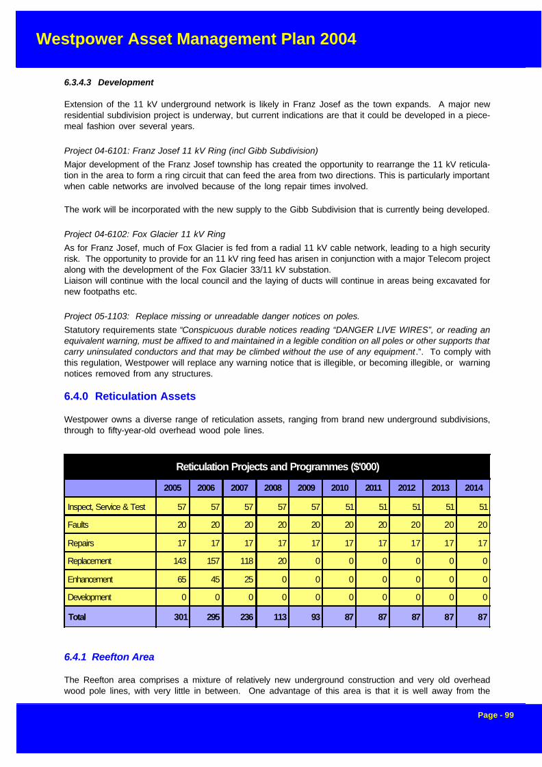
Westpower Asset Management Plan 2004
Page - 99
6.3.4.3 Development
Extension of the 11 kV underground network is likely in Franz Josef as the town expands. A major newresidential subdivision project is underway, but current indications are that it could be developed in a piece-meal fashion over several years.
Project 04-6101: Franz Josef 11 kV Ring (incl Gibb Subdivision)
Major development of the Franz Josef township has created the opportunity to rearrange the 11 kV reticula-tion in the area to form a ring circuit that can feed the area from two directions. This is particularly importantwhen cable networks are involved because of the long repair times involved.
The work will be incorporated with the new supply to the Gibb Subdivision that is currently being developed.
Project 04-6102: Fox Glacier 11 kV Ring
As for Franz Josef, much of Fox Glacier is fed from a radial 11 kV cable network, leading to a high securityrisk. The opportunity to provide for an 11 kV ring feed has arisen in conjunction with a major Telecom projectalong with the development of the Fox Glacier 33/11 kV substation.Liaison will continue with the local council and the laying of ducts will continue in areas being excavated fornew footpaths etc.
Project 05-1103: Replace missing or unreadable danger notices on poles.
Statutory requirements state “Conspicuous durable notices reading “DANGER LIVE WIRES”, or reading anequivalent warning, must be affixed to and maintained in a legible condition on all poles or other supports thatcarry uninsulated conductors and that may be climbed without the use of any equipment.”. To comply withthis regulation, Westpower will replace any warning notice that is illegible, or becoming illegible, or warningnotices removed from any structures.
6.4.0 Reticulation Assets
Westpower owns a diverse range of reticulation assets, ranging from brand new underground subdivisions,through to fifty-year-old overhead wood pole lines.
6.4.1 Reefton Area
The Reefton area comprises a mixture of relatively new underground construction and very old overheadwood pole lines, with very little in between. One advantage of this area is that it is well away from the
Reticulation Projects and Programmes ($'000)
2005 2006 2007 2008 2009 2010 2011 2012 2013 2014
Inspect, Service & Test 57 57 57 57 57 51 51 51 51 51
Faults 20 20 20 20 20 20 20 20 20 20
Repairs 17 17 17 17 17 17 17 17 17 17
Replacement 143 157 118 20 0 0 0 0 0 0
Enhancement 65 45 25 0 0 0 0 0 0 0
Development 0 0 0 0 0 0 0 0 0 0
Total 301 295 236 113 93 87 87 87 87 87

Westpower Asset Management Plan 2004
Page - 100
seacoast and suffers less from the effects of corrosion than most other areas within Westpower. For thisreason, the overhead lines can still be in serviceable condition at an older age than in other areas.
6.4.1.1 Maintenance
(i) Routine Patrols and Inspections
As with distribution lines, the 2004-05 financial year will see the continuation of the condition assessmentprogramme. Each line (feeder) is to be inspected on a rolling 5-year basis, covering 20% of the route lengthper year. During the inspection every aspect of the line is checked.
As for other areas, it is expected that this will form the basis of a repair programme involving individualcomponent replacements throughout the planning period.
Fault patrols and fault repairs are carried out on an as required basis.
(ii) Faults
Faults are limited to the occasionally substation fuse blowing or the failure of a pole, either during high winds,or when hit by a vehicle.
Fault staff in the area, are able to handle these faults locally.
(iii) Repairs and Refurbishment
Any poles identified as reaching replacement criteria as a result of the pole inspection programme will bereplaced as required, and if the level in particular sections of line exceeds 50% of the line value, this will beupgraded to a replacement programme for that section.
Reticulation Projects ($'000)
ID Act Description Area 2005 2006 2007 2008 2009 2010 2011 2012 2013 2014
05-5201 E Iveagh Bay Underground ALD4 30 0 0 0 0 0 0 0 0 0
05-4201 RPL Dobson LV Replacement DOB3 75 65 40 0 0 0 0 0 0 0
- RPL Replace overhead 400 V with underground, Condon Street FRZ3 0 0 18 0 0 0 0 0 0 0
- E Hampden Street 400 V Underground Conversion HKK12 0 10 0 0 0 0 0 0 0 0
- E Underground Cable Upgrades (Rolleston St) HKK12 0 10 0 0 0 0 0 0 0 0
- RPL 400V line replacement, North End Aharua NGA1 0 21 10 10 0 0 0 0 0 0
05-4202 RPL Blackball LV Replacement NGA1 12 10 10 10 0 0 0 0 0 0
05-5203 E Upgrade of Reefton LV Network RFT3 25 25 25 0 0 0 0 0 0 0
- RPL Upgrade 400V poles and conductor, Blacks Point township RFT3 0 20 20 0 0 0 0 0 0 0
05-4203 RPL Upgrade 400V poles and conductor, Ross township ROS3 30 20 20 0 0 0 0 0 0 0
05-5202 E Upgrade Hokitika link boxes to 3 way switching SYS 10 0 0 0 0 0 0 0 0 0
05-1201 I Replace All Motor Rated Fuses SYS 6 6 6 6 6 0 0 0 0 0
05-4204 RPL LV Upgrade, Okarito Township WAH1 21 21 0 0 0 0 0 0 0 0
05-4205 RPL Replace 400 V poles, Kakapotahi WTH1 5 0 0 0 0 0 0 0 0 0
Total 214 208 149 26 6 0 0 0 0 0

Westpower Asset Management Plan 2004
Page - 101
It is expected that most remedial work will be accomplished through simple component replacement.
(iv) Replacement
There are no reticulation line replacements planned for the upcoming financial year, however LV lines withinthe Blacks Point area will be replaced in future years.
6.4.1.2 EnhancementWith the development of the Macraes gold mine, the economic outlook for Reefton is expected to be bullish.Some upgrading of the LV network will be required to met expected growth demand in the area.
Project 05-5203: Upgrade of Reefton LV Network
This project will be run in conjunction with the "Upgrade 11 kV Line - Reefton Ring". An upgrade of the 400V reticulation supplying Reefton will help alleviate any anticipated shortfall in capacity, along with the replace-ment of any poles not capable of withstanding new design loads.
6.4.1.3 Development
There are no significant development works planned for the Reefton area. Any development that does occurwill be on the basis of new customer requirements.
6.4.2 Greymouth Area
The comments that applied to Reefton reticulation assets apply also to Greymouth, except that the relativeamount of very old wood pole lines is greatly reduced. The reason for this is the major replacement programmecompleted in the early 1990’s as discussed in section 5.3.1.2
6.4.2.1 Maintenance
(i) Routine Patrols and Inspections
As with Reefton, a detailed condition assessment programme will be continued.
Fault patrols and fault repairs are carried out on an as required basis.
(ii) Faults
Faults are limited to the occasionally substation fuse blowing or the failure of a pole, either during high winds,or when hit by a vehicle.
Fault staff in the area are able to handle these faults locally.
(iii) Repairs and Refurbishment
Any poles identified as reaching replacement criteria as a result of the pole inspection programme will bereplaced as required, and if the level in particular sections of line exceeds 50% of the line value, this will beupgraded to a replacement programme for that section.
It is expected that most remedial work will be accomplished through simple component replacement.
Project 05-1201: Replace all motor rated fuses
Motor rated fuses were installed to allow a certain amount of overload to be applied to prevent fusing. Thissituation is quite legal but general purpose fuses of Q1 or Q2 charateristic may be more appropriate. Asmotor rated fuses are found they shall be replaced.

Westpower Asset Management Plan 2004
Page - 102
(iv) Replacement
Project 05-4201: Dobson LV Replacement
The vast majority of wooden LV poles in the Dobson township are in need of replacement. These poles havebeen condemned during a recent condition assessment of the area. In all 47 poles have been identified, 3 ofthese being stub poles, while one is a transformer structure. The section of LV along the Main Road requiresa new PVC neutral strung, while Namu PVC shall replace all LV along Moa and the top end of Herald Streets.This project in be completed in stages over a 3 year period.
Project 05-4202: Blackball LV Replacement
Several LV poles from Brodie St to the school in Blackball are in urgent need of replacement. These polesshall be replaced along with 210 m of Kutu PVC conductor strung from S340 to the school.
6.4.2.2 Enhancement
As most of the reticulation in the Greymouth area has recently been rebuilt, there is unlikely to be a require-ment for capacity enhancement. There is a possibility that some small areas may require this work howeveras a result of in-fill development.
Project 05-5201: Iveagh Bay Underground
There are a number of subdivisions planned for the Iveagh Bay area, the full extent is not yet known. Theexisting 11 kV and 400 V assets in the bay are at the end of their economic life and may not be positionedcorrectly for the future. With the increased load that is likely to come on and the new layout some funds willbe required to bring new supply to the developers Lots. A provisional sum is included.
6.4.2.2 Development
New subdivisions often involve the development of reticulation networks that are handed over to Westpoweron completion. In most cases the developer builds these to Westpower’s standards.
6.4.3 Hokitika Area
Most of the reticulation in Hokitika has been undergrounded, as part of major replacement programmes inthe 1980’s and as a result these assets are in excellent condition. Only a small number of pockets ofoverhead reticulation remain, and those that do are concrete pole lines, also in good condition
(i) Routine Patrols and Inspections
No planned inspections are planned on the underground reticulation.
Fault patrols and fault repairs are carried out on an as required basis.
(ii) Faults
Faults are limited to the occasional substation fuse blowing or the failure of a pole, either during high winds,or hit by a vehicle.
Fault staff in the area, are able to handle these faults locally.
(iii) Repairs and Refurbishment
It is expected that most remedial work will be accomplished through simple component replacement.

Westpower Asset Management Plan 2004
Page - 103
(iv) Replacement
Project 05-4203: Upgrade 400V poles and Conductor, Ross Township.
This project, which is to span three years, comprises of the replacement of all substandard low voltage poleswithin the Ross township.
6.4.3.2 Enhancement
As most of the reticulation in the Hokitika area is already underground with significant spare capacity, there isunlikely to be a requirement for capacity enhancement.
No further undergrounding work is planned unless subsidised by the local District Council or the end user.
An exception to this is the case where a small section of overhead line is replaced in an otherwise under-ground area for instance.
Project 05-5202: Upgrade Hokitika Link Boxes to 3 Way Switching
As a means of reducing the installation cost, many LV link boxes in the Hokitika Area consist of a two sets oflinks, even when three separate LV feeders meet at that point. This reduces the operational flexibility of thesystem through reducing the number of configurations that can be utilized. These link boxes will be upgradedto provide for three sets of links to gain maximum flexibility and improve alternative supply options for con-sumers.
6.4.3.3 Development
New subdivisions often involve the development of reticulation networks that are handed over to Westpoweron completion. In most cases the developer builds these to Westpower’s standards.
6.4.4 South Westland
Most of the reticulation in the townships of Harihari, Franz Josef and Fox Glacier was undergrounded as partof major replacement programmes in the 1980’s and, as a result, these assets are in excellent condition.Only a small number of pockets of overhead reticulation remain, and those that do are concrete pole lines,also in good condition
(i) Routine Patrols and Inspections
No planned inspections are planned on the underground reticulation.
Fault patrols and fault repairs are carried out on an as required basis.
(ii) Faults
Faults are limited to the occasional substation fuse blowing or the failure of a pole, or when a pillar-box is hitby a vehicle.
Fault staff from the area are, able to handle these faults locally.
(iii) Repairs and Refurbishment
It is expected that most remedial work will be accomplished through simple component replacement.

Westpower Asset Management Plan 2004
Page - 104
(iv) Replacement
Project 05-4204: LV Upgrade, Okarito Township
With the poor state of the 400V network and the 'resort' designation of the Okarito township, undergroundingof this LV appears to be the most appropriate option. The 04-05 financial year will see 180 m of appropriatelyrated 400 V cable laid along The Parade to replace the 5 substandard hardwood poles currently in place.The following year, a further 280 m of appropriately rated 400 V cable will be buried on the sea side of TheStrand replacing the seven existing substandard hardwood poles.
Project 05-4205: Replace 400 V poles, Kakaotahi
A recent inspection revealed three hardwood LV poles and associated fittings at Beach Road, Kakapotahiare in need of replacement. In addition a new 400 V PVC conductor and neutral is required to replace theexisting bare conductors. Several service poles require replacement, however these shall be undertakenwith the Service Pole Replacement project.
6.4.4.2 Enhancement
No enhancement projects are planned for this area, as there is ample capacity generally available.
6.4.4.3 Development
New subdivisions often involve the development of reticulation networks that are handed over to Westpoweron completion. In most cases the developer builds these to Westpower’s standards.
6.5.0 Services
In general, Westpower does not carry out maintenance on customer owned service lines. These are theresponsibility of the customer to maintain and they can use any competent contractor to do so.There are several exceptions to this general rule however including
• replacement of blown service fuses due to faults• repair of substandard service lines where these were never brought up to standard prior to
transferring to the customer• replacement of service poles on the street where these were previously shared with Telecom and
are now substandard• repairs to network connection equipment• repairs to service spans across road reserve
Financial control procedures mean, that only approved work is carried out , and that the customer will berequired to pay for most work on customer-owned service lines.
The ongoing replacement of re-wireable fuses with HRC types as part of LV replacement projects has signifi-cantly reduced the number of premature service fuse failures, which should be reflected in a reduced cost offault work.
Service lines are generally owned by the end customer and as such are not maintained by Westpower,however, as discussed above, there are some notable exceptions to this and these create a maintenanceliability for Westpower
6.5.1 Service Poles
The condition assessment programme to be initiated this year is to include the assessment of service polesnot on private property. Any poles found to be in need of replacement will be done so as a high priority.These poles pose a Health and Safety risk which must be mitigated as soon as possible.

Westpower Asset Management Plan 2004
Page - 105
Project 05-1301: Service Pole Replacement
This project has been initiated to ensure funds are available to replace any substandard service pole foundon the network. These poles pose a health and safety risk so therefore the risk must be mitigated on a highpriority basis.
6.6 Zone Substations
Service Projects ($'000)
Area 2004 2005 2006 2007 2008 2009 2010 2011 2012 2013
D New Service Connections SYS 55 55 55 55 55 55 55 55 55 55
I Service Pole Replacement SYS 35 35 35 35 35 35 35 35 35 35
Total 90 90 90 90 90 90 90 90 90 90
Service Projects and Programmes ($'000)
2005 2006 2007 2008 2009 2010 2011 2012 2013 2014
Inspect, Service & Test 35 35 35 35 35 35 35 35 35 35
Faults 18 18 18 18 18 18 18 18 18 18
Repairs 25 25 25 25 25 25 25 25 25 25
Replacement 0 0 0 0 0 0 0 0 0 0
Enhancement 0 0 0 0 0 0 0 0 0 0
Development 55 55 55 55 55 55 55 55 55 55
Total 133 133 133 133 133 133 133 133 133 133
Zone Substation Projects and Programmes ($'000)
2005 2006 2007 2008 2009 2010 2011 2012 2013 2014
Inspect, Service & Test 250 267 263 213 178 138 138 148 138 338
Faults 12 12 12 12 12 12 12 12 12 12
Repairs 19 19 19 19 19 19 19 19 19 19
Replacement 35 260 0 0 0 0 0 0 0 0
Enhancement 146 390 120 270 0 0 0 0 0 0
Development 3150 3415 0 0 2200 0 0 500 0 0
Total 3611 4362 413 513 2408 168 168 678 168 368
Westpower Asset Management Plan 2004
Page - 106
6.6.1 Inspections, Servicing and Testing
Westpower’s station equipment is to be routinely inspected, tested and serviced in accordance with therequirements of Westpower’s “Maintenance Standards” relevant to the actual equipment. These standardrequirements which define the scope and frequency of work, are reflected in maintenance schedules forindividual stations.Equipment servicing is categorised as either “minor” (non-invasive), or “major” (invasive). Testing and in-spections are categorised as minor. Typical frequencies are:
• minor service - every 2 years• major service - every 4 years
The intervals vary according to the equipment and its location. Special inspections and tests are also in-cluded in maintenance schedules or may be arranged as required.
Work identified as a result of the routine inspections and tests is budgeted for as repairs and refurbishment.
6.6.1.1 Station Inspections and Testing
Westpower’s station maintenance involves a general monthly station inspection in accordance with specifiedprocedures from which reports are derived.
Other station inspections incorporate annual thermovision inspections, fire protection and security.
6.6.1.2 Switchgear
Oil insulated switchgear is regularly inspected and the oil is changed as necessary depending on the resultsof breakdown tests, or when there are obvious visual signs of high carbon content. Extra servicing is carriedout where the switchgear has sustained a higher than normal level of “heavy” faults.
Male and female contacts are checked for wear and dressed or replaced as necessary.
Vacuum or SF6 gas insulated switchgear undergoes regular visual inspection including checks of SF6 gaspressure.
A baseline ultrasonic discharge investigation was carried out early in 1999 for substations with indoor 11 kVswitchgear, and this has formed the basis for future studies which will be carried out at regular intervals.
Thermovision inspections are carried out on all switchgear on an annual basis.
6.6.1.3 Power Transformer Servicing and Testing
As part of Westpower’s maintenance programme, all major power transformers have an annual minor main-tenance service which encompasses a visual inspection, routine diagnostic tests and minor repair work inaccordance with Westpower standards which incorporate manufacturers’ recommendations and Westpower’sexperience.
In general, maintenance on the transformers consists of maintaining oil within acceptable dielectric andacidity standards, patching up corrosion, fixing oil leaks and annual diagnostic tests on the insulating oil. Inaddition the units fitted with on-load tapchangers require periodic inspection of the tapchangers and thecontacts are dressed or replaced as necessary. Additional remedial work required outside the scope of themaintenance contract is referred to Westpower for further action and budgeted as repairs and refurbishment.
Westpower Asset Management Plan 2004
Page - 107
(i) Oil Testing- Oil Conductivity and Dissolved Gas Analysis
Over the last three years, all Zone Substations have had dissolved gas analysis tests carried out and thisidentified potential problems that need monitoring. This will be followed up by further annual Oil Conductivityand DGA tests until trends are reliably established. Once this is done, the period will be reviewed, possiblyon an individual unit basis.
Costing for minor maintenance is very dependent on location and based on the present maintenance expen-diture.
Costing for major maintenance, i.e. on-load tapchangers, is not only dependent on the location of the site butalso the usage and types of unit and is such that some units have to be serviced every two years and othersevery six years.
6.6.1.4 Structures and Buswork
The routine maintenance of structures, buswork and disconnectors is usually performed simultaneouslywhen a particular circuit or section of bus is released from service.
Disconnectors are scheduled for servicing every 2 years but this is extended up to 4 years when there areoperational difficulties in getting a maintenance outage. The servicing is non-invasive and is generally limitedto checks, adjustments, lubrication, cleaning and corrosion control.
Buswork and associated hardware is inspected and maintained with disconnectors, and includes checkingand cleaning of insulators. At sites, which are subject to atmospheric pollution, insulator cleaning must bedone more frequently than usual.
Structures are maintained up to a maximum interval of 4 years and work is limited to corrosion control,general check of fixings, and removal of any debris. Wood poles are subject to a check for signs of rotting.It has been decided that for most stations earth testing can be carried out every 5 years, and this will becomethe practice in future.
6.6.1.5 Instrument Transformers
As part of Westpower’s maintenance programme all instrument transformers have an annual minor mainte-nance service which encompasses a visual inspection, routine diagnostic tests and minor repair work. Addi-tional remedial work required is outside the scope of the maintenance contract and is referred to Westpowerfor action.
Typically, the minor maintenance costs based on present maintenance for instrument transformers is in therange $40-$220 depending on type and voltage.
(i) Other Station Equipment
The new battery banks are virtually maintenance free and only a basic inspection and charger check isnecessary.
Fire protection and security alarm systems are to be inspected every 3 months and serviced annually. Otherswitchyard equipment such as local service transformers, surge diverters, line traps, cables, etc are main-tained as necessary when the associated circuit is taken out of service.
6.6.2 Fault Repairs
Equipment failures occur randomly and without warning and range from a simple circuit breaker mechanism

Westpower Asset Management Plan 2004
Page - 108
failure due to a broken circlip to a costly transformer winding failure. The cost budgeted is the cost to restoresupply or the service following the failure, not the cost of any repair work after supply or service has beenrestored.
It is estimated that there are approximately two such faults per month. It is expected this frequency will bereduced as aged/defective equipment is refurbished or replaced.
The projected expenditure is based on actual expenditure incurred in recent years. It is not practicable toallocate projected expenditure against each sub station asset category given the range of faults, which canoccur.
6.6.3 Planned Repairs and Refurbishment
This area of expenditure includes corrective work identified following inspections and tests and while under-taking routine maintenance or following equipment failures. The magnitude and costs of the work can varygreatly.
The planned expenditure also includes the cost of materials and spares.
6.3.3.1 Power Transformers
The major cause of power transformer failures is winding and internal connection faults. These are causedin general by electrical through faults or lightning strikes.
The other major internal maintenance on a power transformer is oil refurbishment and desludging which iscarried out as required based on oil acidity test results. It is not expected that this will be required on any ofWestpower’s units within the planning period
(i) Radiator Replacement
Radiator replacement is only carried out on coolers where the design of the radiators or extent of corrosionmeans repairs cannot be carried out satisfactorily
The corrosion occurs after 20 or more years of age in transformers in corrosive environments (such ascoastal). The radiators are replaced only once in the life of a transformer. Only two of Westpower’s currentpower transformers meet this criteria.
(ii) Repainting
Painting is carried out on a regular basis at a period of generally between 10 to 15 years depending on siteconditions. It is planned to paint approximately 1 unit per year over the period 2002-2011
(iii) Other Equipment
Ongoing repairs are required to a variety of other station equipment including portable earthing equipmentand battery banks.
6.6.4 Replacement Programmes
Westpower has formulated its replacement programme based on the following criteria:
Westpower Asset Management Plan 2004
Page - 109
6.6.4.1 Circuit Breakers - Outdoor
In line with the practice of overseas utilities as reported by CIGRE, Westpower has a policy, subject toproject-specific economic analysis, of replacement rather than life extension of aged deficient bulk oil andminimum oil circuit breakers by major refurbishment.
Circuit breakers are also replaced for the following reasons:• where they have high maintenance costs• where they are unreliable due to an increased defect rate• where a system node requires a maintenance free circuit breaker i.e. maintenance outages cannot
be tolerated
There are generic problems associated with minimum oil circuit breakers resulting from moisture ingress,which presents a safety hazard to personnel working in switchyards. This results in random explosive fail-ures where porcelain fragments can travel up to 50 metres and cause considerable damage to adjacentequipment. Such an incident has occurred on one of Westpower’s minimum oil circuit breakers due toinappropriate levels of maintenance.
It is internationally recognised that forty years is generally the “time expired” life of circuit breakers. Sometypes have an economic life greater or less than this figure. Bulk oil breakers generally have a longer life,while minimum oil breakers typically last only 30-35 years.
While age is not itself criteria for replacement, analysis based on likely total economic lives for each type,make and model of circuit breaker provides a means of assessing likely future replacement requirements.The replacements themselves would be determined by safety, economics and reliability assessments at thetime.
Westpower currently has four 66 kV minimum oil circuit breakers, and a replacement strategy is being formu-lated that will ensure ongoing performance of these sites.
6.6.4.2 Circuit Breakers - Indoor
Metalclad switchgear deteriorates with age resulting in ageing of insulation materials, such as formation ofvoids and penetration of moisture. Visible compound leaks and audible corona discharge often accompanythis.
Replacement is justified primarily on reliability/risk of failure grounds and customer service operating limita-tions. There is potential for explosive failure, which occurs infrequently (approximately one such failure everyten years). Recent failures of SO-HI metalclad switchgear has led to the Greymouth 11 kV switchboard,being the only SO-HI type in Westpower’s area, getting replaced in 2003.
As contractors work in close proximity to the equipment and the equipment is oil filled there is an increasedrisk of personal injury. Overseas utilities have adopted designs such that new oil filled equipment is notinstalled indoors and blast walls have been installed between old equipment and places where contractorsare required to work for extended periods.
Modern SF6/vacuum replacement installations with air insulated bus chambers rather than the old com-pound insulated types are virtually maintenance free. There is a high cost associated with maintenance ofold oil filled and compound insulated equipment, which requires annual major service and frequent faultmaintenance.
The typical economic life of Westpower’s indoor metalclad switchgear installations (typically 11 kV) has beenassessed to be 50 years based on past experience. At present only a small percentage are over 20 yearsold.
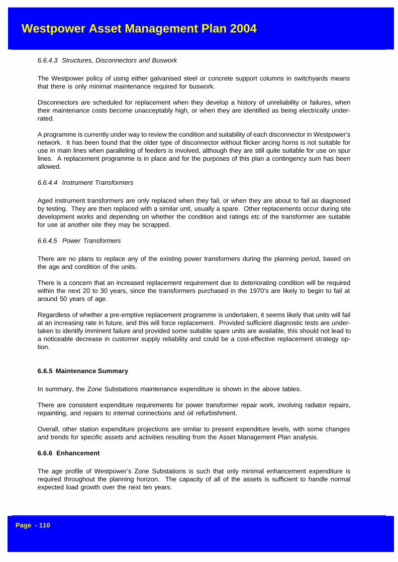
Westpower Asset Management Plan 2004
Page - 110
6.6.4.3 Structures, Disconnectors and Buswork
The Westpower policy of using either galvanised steel or concrete support columns in switchyards meansthat there is only minimal maintenance required for buswork.
Disconnectors are scheduled for replacement when they develop a history of unreliability or failures, whentheir maintenance costs become unacceptably high, or when they are identified as being electrically under-rated.
A programme is currently under way to review the condition and suitability of each disconnector in Westpower’snetwork. It has been found that the older type of disconnector without flicker arcing horns is not suitable foruse in main lines when paralleling of feeders is involved, although they are still quite suitable for use on spurlines. A replacement programme is in place and for the purposes of this plan a contingency sum has beenallowed.
6.6.4.4 Instrument Transformers
Aged instrument transformers are only replaced when they fail, or when they are about to fail as diagnosedby testing. They are then replaced with a similar unit, usually a spare. Other replacements occur during sitedevelopment works and depending on whether the condition and ratings etc of the transformer are suitablefor use at another site they may be scrapped.
6.6.4.5 Power Transformers
There are no plans to replace any of the existing power transformers during the planning period, based onthe age and condition of the units.
There is a concern that an increased replacement requirement due to deteriorating condition will be requiredwithin the next 20 to 30 years, since the transformers purchased in the 1970’s are likely to begin to fail ataround 50 years of age.
Regardless of whether a pre-emptive replacement programme is undertaken, it seems likely that units will failat an increasing rate in future, and this will force replacement. Provided sufficient diagnostic tests are under-taken to identify imminent failure and provided some suitable spare units are available, this should not lead toa noticeable decrease in customer supply reliability and could be a cost-effective replacement strategy op-tion.
6.6.5 Maintenance Summary
In summary, the Zone Substations maintenance expenditure is shown in the above tables.
There are consistent expenditure requirements for power transformer repair work, involving radiator repairs,repainting, and repairs to internal connections and oil refurbishment.
Overall, other station expenditure projections are similar to present expenditure levels, with some changesand trends for specific assets and activities resulting from the Asset Management Plan analysis.
6.6.6 Enhancement
The age profile of Westpower’s Zone Substations is such that only minimal enhancement expenditure isrequired throughout the planning horizon. The capacity of all of the assets is sufficient to handle normalexpected load growth over the next ten years.
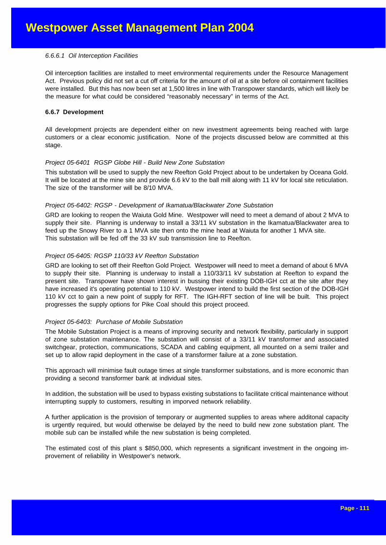
Westpower Asset Management Plan 2004
Page - 111
6.6.6.1 Oil Interception Facilities
Oil interception facilities are installed to meet environmental requirements under the Resource ManagementAct. Previous policy did not set a cut off criteria for the amount of oil at a site before oil containment facilitieswere installed. But this has now been set at 1,500 litres in line with Transpower standards, which will likely bethe measure for what could be considered “reasonably necessary” in terms of the Act.
6.6.7 Development
All development projects are dependent either on new investment agreements being reached with largecustomers or a clear economic justification. None of the projects discussed below are committed at thisstage.
Project 05-6401 RGSP Globe Hill - Build New Zone Substation
This substation will be used to supply the new Reefton Gold Project about to be undertaken by Oceana Gold.It will be located at the mine site and provide 6.6 kV to the ball mill along with 11 kV for local site reticulation.The size of the transformer will be 8/10 MVA.
Project 05-6402: RGSP - Development of Ikamatua/Blackwater Zone Substation
GRD are looking to reopen the Waiuta Gold Mine. Westpower will need to meet a demand of about 2 MVA tosupply their site. Planning is underway to install a 33/11 kV substation in the Ikamatua/Blackwater area tofeed up the Snowy River to a 1 MVA site then onto the mine head at Waiuta for another 1 MVA site.This substation will be fed off the 33 kV sub transmission line to Reefton.
Project 05-6405: RGSP 110/33 kV Reefton Substation
GRD are looking to set off their Reefton Gold Project. Westpower will need to meet a demand of about 6 MVAto supply their site. Planning is underway to install a 110/33/11 kV substation at Reefton to expand thepresent site. Transpower have shown interest in bussing their existing DOB-IGH cct at the site after theyhave increased it's operating potential to 110 kV. Westpower intend to build the first section of the DOB-IGH110 kV cct to gain a new point of supply for RFT. The IGH-RFT section of line will be built. This projectprogresses the supply options for Pike Coal should this project proceed.
Project 05-6403: Purchase of Mobile Substation
The Mobile Substation Project is a means of improving security and network flexibility, particularly in supportof zone substation maintenance. The substation will consist of a 33/11 kV transformer and associatedswitchgear, protection, communications, SCADA and cabling equipment, all mounted on a semi trailer andset up to allow rapid deployment in the case of a transformer failure at a zone substation.
This approach will minimise fault outage times at single transformer suibstations, and is more economic thanproviding a second transformer bank at individual sites.
In addition, the substation will be used to bypass existing substations to facilitate critical maintenance withoutinterrupting supply to customers, resulting in imporved network reliability.
A further application is the provision of temporary or augmented supplies to areas where additonal capacityis urgently required, but would otherwise be delayed by the need to build new zone substation plant. Themobile sub can be installed while the new substation is being completed.
The estimated cost of this plant s $850,000, which represents a significant investment in the ongoing im-provement of reliability in Westpower’s network.

Westpower Asset Management Plan 2004
Page - 112
Zone Substation Projects ($'000)
ID Act Description Area 2005 2006 2007 2008 2009 2010 2011 2012 2013 2014
05-1401 I Arnold transformer refurbishment & maintenance ALD 15 0 0 0 0 0 0 0 0 0
- I Cronadun regulator refurbishment & maintenance CRN 0 3 0 0 0 0 0 0 0 0
05-5402 E Zone Sub out going 11 kV cable isolation DIL 16 35 0 0 0 0 0 0 0 0
- I Dobson transformer refurbishment & maintenance DOB 0 15 0 0 0 0 0 0 0 0
05-6404 D Install Ripple Plant Dobson DOB 100 0 0 0 0 0 0 0 0 0
- E Fox regulator refurbishment and maintenance FOX 0 0 0 150 0 0 0 0 0 0
- I Fox transformer refurbishment & maintenance FOX 0 0 0 0 0 0 0 0 0 20
- I Franz transformer refurbishment & maintenance FRZ 0 60 0 0 0 0 0 0 0 0
05-1405 I FRZ 11 kV metering unit bus re-arrangement FRZ 25 0 0 0 0 0 0 0 0 0
05-6401 D RGSP Globe Hill - Build New Zone Substation GLB 200 600 0 0 0 0 0 0 0 0
05-5404 E Replace GYM Protection GYM 20 200 0 0 0 0 0 0 0 0
- RPL 66 kV minimum oil CB replacement GYM 0 240 0 0 0 0 0 0 0 0
- RPL Replace ODJB's, Greymouth Substation GYM 0 20 0 0 0 0 0 0 0 0
- I Greymouth transformer refurbishment & maintenance GYM 0 0 0 30 0 0 0 0 0 150
- I Paint Gantry Steelwork at Grey Substation GYM 0 20 30 0 0 0 0 0 0 0
- D SWGR Zone Sub Upgrade - Harihari Sub HHI 0 0 0 0 2000 0 0 0 0 0
- I Harihari regulator refurbishment & maintenance HHI 0 0 0 0 10 0 0 0 0 0
- I Harihari transformer refurbishment & maintenance HHI 0 0 0 0 10 0 0 0 0 0
05-1403 I Hokitika transformer refurbishment and maintenance HKK 15 0 20 0 0 0 0 0 0 0
05-1402 I Longford regulator refurbishment & maintenance LNG 3 20 0 0 0 0 0 0 0 0
- D Build New Zone Sub - Kokatahi KOK 0 0 0 0 0 0 0 500 0 0
- I Kumara transformer refurbishment & maintenance KUM 0 0 0 0 0 0 0 0 0 20
05-1404 I Ngahere transformer refurbishment & maintenance NGH 20 0 0 0 0 0 0 0 0 0
05-5405 E Ngahere 11 kV bus re-arrangement NGH 15 0 0 0 0 0 0 0 0 0
- D Pike River Coal - Development of Pike Zone Sub PIKE 0 800 0 0 0 0 0 0 0 0
- I Rapahoe transformer refurbishment & maintenance RAP 0 0 0 15 0 0 0 0 0 0
04-6405 D RGSP 110/33 kV Reefton Substation RFT 1000 1515 0 0 0 0 0 0 0 0
05-1406 I Reefton transformer refurbishment & maintenance RFT 5 0 0 0 20 0 0 0 0 0
- I Cronadun regulator refurbishment & maintenance CRN 0 3 0 0 0 0 0 0 0 0
- D SWGR Zone Sub Upgrade - Ross Sub RSS 0 0 0 0 100 0 0 0 0 0
- I Ross regulator refurbishment & maintenance RSS 0 8 0 0 0 0 0 0 0 0
- I Ross transformer refurbishment & maintenance RSS 0 0 15 0 0 0 0 0 0 0
- D Pike River Coal - Development of Ahaura Tee SYS 0 500 0 0 0 0 0 0 0 0
05-6403 D Purchase of Mobile Substation SYS 850 0 0 0 0 0 0 0 0 0
05-6402 D RGSP - Development of Ikamatua/Blackwater Sub SYS 1000 0 0 0 0 0 0 0 0 0
05-5401 E Install 33 kV Bypass Switches SYS 25 25 0 0 0 0 0 0 0 0
05-1410 I Earthing Review of Zone Subs SYS 15 0 0 0 0 0 0 0 0 0
05-1407 I On-Line oil treatment SYS 25 15 15 15 15 15 15 15 15 15
05-1411 I Perform Oil tests at Zone Subs SYS 20 20 20 20 20 20 20 20 20 20
05-5403 E Install New Ripple Control Static Convertors SYS 60 120 120 120 0 0 0 0 0 0
05-5406 E Retrofit Porcelain Lightning Arresters SYS 10 10 0 0 0 0 0 0 0 0
05-1409 I Zone Sub Building Climate Control SYS 5 0.5 0.5 0.5 0.5 0.5 0.5 0.5 0.5 0.5
05-1408 I Zone Sub Landscaping and Beautification SYS 5 5 5 5 5 5 5 5 5 5
05-1412 I Zone Substation Building Maintenance SYS 10 10 10 10 10 10 10 10 10 10
05-4401 RPL Replace 11 kV Station Class Surge Arrestors SYS 15 0 0 0 0 0 0 0 0 0
05-4402 RPL Replace 33 kV Station Class Surge Arrestors SYS 20 0 0 0 0 0 0 0 0 0
- I Wahapo transformer refurbishment & maintenance WAH 0 0 60 0 0 0 0 0 0 0
- D SWGR Zone Sub Upgrade - Waitaha Sub WTH 0 0 0 0 100 0 0 0 0 0
- I Waitaha regulator refurbishment & maintenance WTH 0 0 0 0 0 0 0 10 0 0
I Whataroa transformer refurbishment & maintenance WTH 0 0 0 15 0 0 0 0 0 0
- I Whataroa regulator refurbishment & maintenance WTH 0 0 0 0 0 0 0 0 0 10
- I Waitaha transformer refurbishment & maintenance WTH 0 0 0 15 0 0 0 0 0 0
3494 4245 296 396 2291 51 51 561 51 251

Westpower Asset Management Plan 2004
Page - 113
Zone Substation Projects 2004-05
Various Substations
Project 05-5402: Zone Sub out going 11 kV cable isolation
Many subs were built without a disconnector on the outgoing 11 kV feeders to give an isolation point to theCB/feeder cable. A minimum of two undetermined places need a contingent allowed for. Places of interestfor this work are Dillmans and Rapahoe substations.
Project 05-5401: Install 33 kV Bypass Switches
Some key 33 kV CBs require bypass switches to allow their testing. A contingency should be allowed toenable at least two CBs to have bypasses fitted. Actual switches determined by the call up list for testing.NGH and RFT look likely in 2004/2005. From time to time 1002 needs releasing for maintenance. At presentthis requires a zone sub shutdown. It is proposed to install a 33 kV bypass over 1002 to allow the trans-former to remain in service while maintenance is carried out
Project 05-1410: Earthing Review of Zone Subs
Westpower is required to carry out regular earth testing of its Zone Substations as a regulatory and healthand safety issue. The company must also ensure that damage to other plant such as Telecom equipment isminimised in the event of an earth fault, and a survey is currently being carried out of all Zone Substationearth mats to ensure compliance.
Project 05-1407: On-line oil treatment
Many of Westpower’s transformers have significant water content in their oil and the oil is rising in aciditylevels. Once a suitable filter plant is found, it will be rotated around the transformers to reduce the watercontent of oil and improve the acidity. The filter is likely to cost in the region of $25k and then a further $15kper year is required to allow for replacement cartridges and set up costs at each site. It is proposed it the filterwill visit five sites in one year for a two month period each.
Project 05-1411: Perform Oil tests at Zone Subs
An enhanced baseline analysis of transformer oil conductivity and dissolved gases will be continued in the2005 year to gain a better understanding of the asset.
Project 05-5403: Install New Ripple Control Static Convertors
Westpower's current population of ripple injection plants are nearing the end of their economic life with spareparts becoming difficult to obtain. The replacement programme planned involves replacing one critical plantat Greymouth with a modern, high capacity unit and using the plant that has been released from service asspare parts to maintain the other plants. This will extend the life of the remaining units until 2008 at whichtime an annual replacement programme over 3 years will be instituted to upgrade the remaining injectionplants.
Project 05-5406: Retrofit Porcelain Lightning Arrestors
Lightning arrestors can deteriorate over time as they survive the continual stresses of absorbing lightningsurges. In addition, porcelain lightning arrestors can create a safety hazard if they explode while staff areworking in the vicinity. Moreover, many of the older porcelain arrestors were rated at 9 kV, which is some-what lower than the 12 kV rating currently used throughout Westpower's network. (A 12 kV rating must beused when the supply to an area is fed with a Neutral Earthing Resistor) For this reason, a replacementprogram was instituted that a will result in new 12 kV rated polymer arrestors being fitted throughout all ZoneSubstations over the next two years.
Project 05-1409: Zone Sub Building Climate Control
This project was initiated to ensure that equipment, especially that of the electronic kind, enclosed inWestpower's zone substation buildings are kept at the correct temperature and humidity levels. This projectwill see an initial cost, with ongoing maintenance costs.

Westpower Asset Management Plan 2004
Page - 114
Project 05-1408: Zone Sub Landscaping and Beautification
This is an ongoing project which incorporates, as the title suggests, landscaping and gardening work aimedat improving the amenity values at Westpower's zone substation sites.
Project 05-1412: Zone Substation Building Maintenance
This too is an ongoing project which can include building maintenance such as cladding repairs, spoutingrepairs etc on all of Westpower's zone substation buildings.
Project 05-4401: Replace 11kV Station Class Surge Arrestors
Some of the older station class arrestors used on transformers in Zone Substations do not meet Westpower'scurrent standards. This project was initiated last year and will continue in the 2005 year.
Project 05-4402: Replace 33 kV Station Class Surge Arrestors
As with project 05-4401 above, except this project covers the 33 kV arrestors used on HV terminals oftransformers.
Reefton Substation
Project 05-1406: Reefton Zone Sub transformer refurbishment and maintenance
New in 1999, paint radiators 2005, paint unit and OLTC overhaul 2009.
Arnold Substation
Project 05-1401: Arnold transformer, refurbishment and maintenance
T1 new in 1995, paint radiators and unit in 2005, no major work foreseen for 15 years.
Dobson Substation
Project 05-6404: Install Ripple Plant Dobson
When Buller Electricity installed their new substation they realised that a ripple plant on the 11 kV was abetter solution than continuing with 33 kV injection. Their 33 kV plant is in good condition so Westpowersecured it for Dobson substation. This will be installed in a purpose built shed and connected to the 33 kVbus via a new recloser.
Greymouth Substation
Project 05-5404: Replace GYM Protection
Although the existing protection equipment on the banks at Greymouth is still quite serviceable, it does notprovide the communication and additional protection functions used in modern schemes. In particular, adap-tive settings, which are required to maintain protective discrimination under differing system configurations,such as bank outages, are not available with the current scheme. It is proposed to replace the existingCombiFlex relays with SEL units as installed in Hokitika recently
Franz Substation
Project 05-1405: FRZ 11 kV metering unit bus re-arrangement
The FRZ 11 kV metering unit has 100/50/5 CT ratios. This will become under rated in time as the load grows.The unit could be removed from service, now metering can be carried out in the new relay on 1612. In theposition of the metering unit, an isolating spar type ABS can be installed to allow the 11 kV bus to be livenedfrom local temporary generation or a mobile substation. Single phase VTs will need to be installed as wellRiser class surge arrestors.
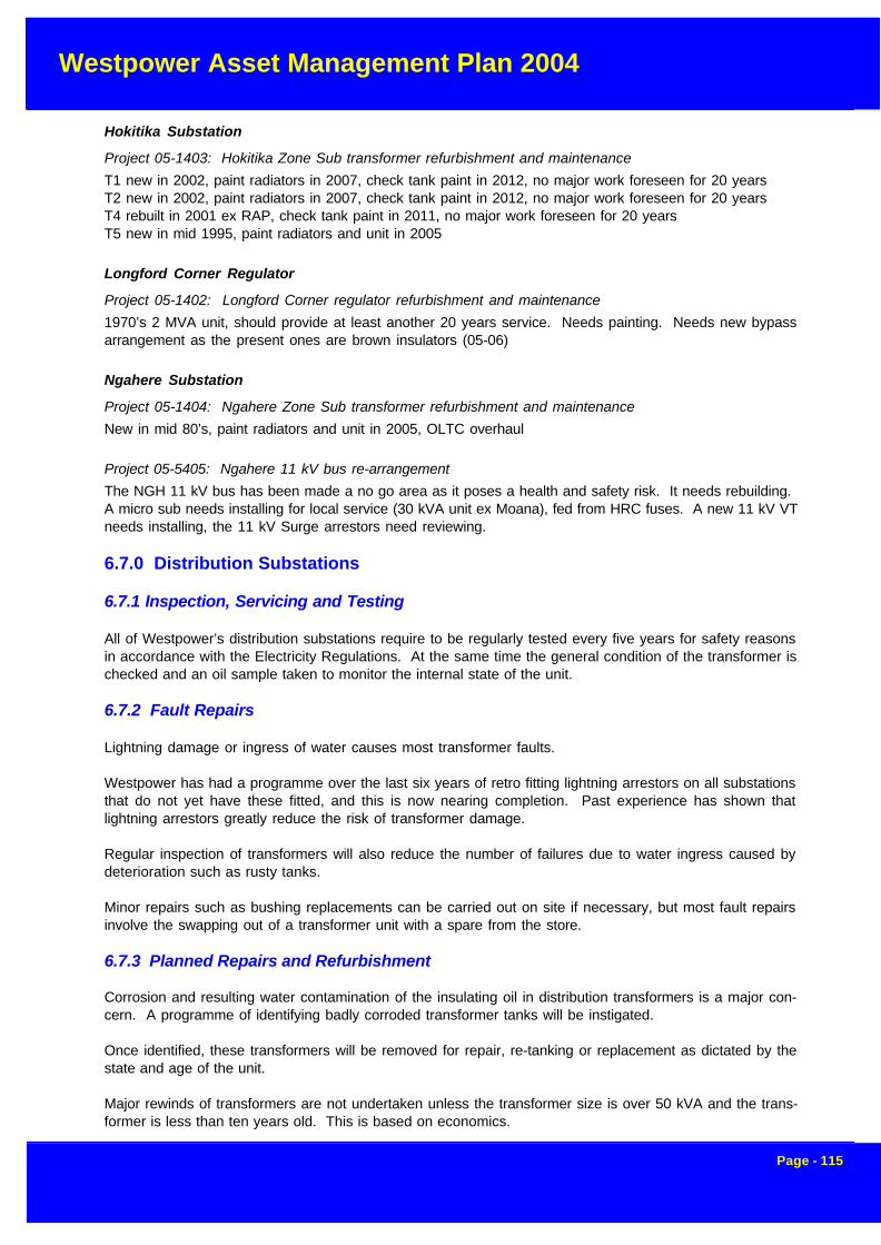
Westpower Asset Management Plan 2004
Page - 115
Hokitika Substation
Project 05-1403: Hokitika Zone Sub transformer refurbishment and maintenance
T1 new in 2002, paint radiators in 2007, check tank paint in 2012, no major work foreseen for 20 yearsT2 new in 2002, paint radiators in 2007, check tank paint in 2012, no major work foreseen for 20 yearsT4 rebuilt in 2001 ex RAP, check tank paint in 2011, no major work foreseen for 20 yearsT5 new in mid 1995, paint radiators and unit in 2005
Longford Corner Regulator
Project 05-1402: Longford Corner regulator refurbishment and maintenance
1970’s 2 MVA unit, should provide at least another 20 years service. Needs painting. Needs new bypassarrangement as the present ones are brown insulators (05-06)
Ngahere Substation
Project 05-1404: Ngahere Zone Sub transformer refurbishment and maintenance
New in mid 80’s, paint radiators and unit in 2005, OLTC overhaul
Project 05-5405: Ngahere 11 kV bus re-arrangement
The NGH 11 kV bus has been made a no go area as it poses a health and safety risk. It needs rebuilding.A micro sub needs installing for local service (30 kVA unit ex Moana), fed from HRC fuses. A new 11 kV VTneeds installing, the 11 kV Surge arrestors need reviewing.
6.7.0 Distribution Substations
6.7.1 Inspection, Servicing and Testing
All of Westpower’s distribution substations require to be regularly tested every five years for safety reasonsin accordance with the Electricity Regulations. At the same time the general condition of the transformer ischecked and an oil sample taken to monitor the internal state of the unit.
6.7.2 Fault Repairs
Lightning damage or ingress of water causes most transformer faults.
Westpower has had a programme over the last six years of retro fitting lightning arrestors on all substationsthat do not yet have these fitted, and this is now nearing completion. Past experience has shown thatlightning arrestors greatly reduce the risk of transformer damage.
Regular inspection of transformers will also reduce the number of failures due to water ingress caused bydeterioration such as rusty tanks.
Minor repairs such as bushing replacements can be carried out on site if necessary, but most fault repairsinvolve the swapping out of a transformer unit with a spare from the store.
6.7.3 Planned Repairs and Refurbishment
Corrosion and resulting water contamination of the insulating oil in distribution transformers is a major con-cern. A programme of identifying badly corroded transformer tanks will be instigated.
Once identified, these transformers will be removed for repair, re-tanking or replacement as dictated by thestate and age of the unit.
Major rewinds of transformers are not undertaken unless the transformer size is over 50 kVA and the trans-former is less than ten years old. This is based on economics.
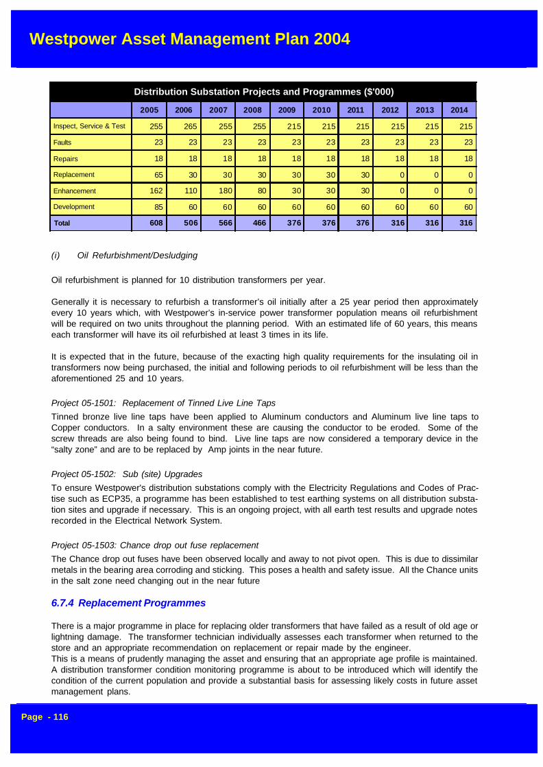
Westpower Asset Management Plan 2004
Page - 116
(i) Oil Refurbishment/Desludging
Oil refurbishment is planned for 10 distribution transformers per year.
Generally it is necessary to refurbish a transformer’s oil initially after a 25 year period then approximatelyevery 10 years which, with Westpower’s in-service power transformer population means oil refurbishmentwill be required on two units throughout the planning period. With an estimated life of 60 years, this meanseach transformer will have its oil refurbished at least 3 times in its life.
It is expected that in the future, because of the exacting high quality requirements for the insulating oil intransformers now being purchased, the initial and following periods to oil refurbishment will be less than theaforementioned 25 and 10 years.
Project 05-1501: Replacement of Tinned Live Line Taps
Tinned bronze live line taps have been applied to Aluminum conductors and Aluminum live line taps toCopper conductors. In a salty environment these are causing the conductor to be eroded. Some of thescrew threads are also being found to bind. Live line taps are now considered a temporary device in the“salty zone” and are to be replaced by Amp joints in the near future.
Project 05-1502: Sub (site) Upgrades
To ensure Westpower's distribution substations comply with the Electricity Regulations and Codes of Prac-tise such as ECP35, a programme has been established to test earthing systems on all distribution substa-tion sites and upgrade if necessary. This is an ongoing project, with all earth test results and upgrade notesrecorded in the Electrical Network System.
Project 05-1503: Chance drop out fuse replacement
The Chance drop out fuses have been observed locally and away to not pivot open. This is due to dissimilarmetals in the bearing area corroding and sticking. This poses a health and safety issue. All the Chance unitsin the salt zone need changing out in the near future
6.7.4 Replacement Programmes
There is a major programme in place for replacing older transformers that have failed as a result of old age orlightning damage. The transformer technician individually assesses each transformer when returned to thestore and an appropriate recommendation on replacement or repair made by the engineer.This is a means of prudently managing the asset and ensuring that an appropriate age profile is maintained.A distribution transformer condition monitoring programme is about to be introduced which will identify thecondition of the current population and provide a substantial basis for assessing likely costs in future assetmanagement plans.
Distribution Substation Projects and Programmes ($'000)
2005 2006 2007 2008 2009 2010 2011 2012 2013 2014
Inspect, Service & Test 255 265 255 255 215 215 215 215 215 215
Faults 23 23 23 23 23 23 23 23 23 23
Repairs 18 18 18 18 18 18 18 18 18 18
Replacement 65 30 30 30 30 30 30 0 0 0
Enhancement 162 110 180 80 30 30 30 0 0 0
Development 85 60 60 60 60 60 60 60 60 60
Total 608 506 566 466 376 376 376 316 316 316

Westpower Asset Management Plan 2004
Page - 117
Westpower has assessed it’s stock of spare transformers and its ability to cover potential failures. At presenta contingency allowance is made to cover this work.
Current levels of transformer replacements are planned to continue. Typical prices for new units range from$3,000 for small single-phase units to $20,000 for urban pad-mount transformers.
Project 05-4501: Wilson LaneSub Rebuild
The switchgear equipment in the two Wilson Lane Sub Buildings is in need of replacement. The existingcircuit breakers and associated switchgear are to be removed and replaced with a new ring main unit. AnRMU, ex-Fox, has already been purchased for this. New 400 V bus works have also been purchased andrequire fitting. A general tidy up of the buildings is required too, including painting and some minor repairs tothe concrete etc.
Project 05-4502: Changeout 300 kVA Tx at S649, Stafford St
The tap changer on the transformer at S649, Stafford St, Hokitika, is incapable of managing a high 11 kVsecondary potential. Therefore the change-out of this transformer has been included in this years budget.
6.7.5 EnhancementProject 05-5501: Uprate S817, Johns Road, Moana
S817 at Johns Road, Moana does not have isolators between the transformer and 400 V bus. A project willbe initiated to install 630 A isolators to this site.
Project 05-5502: Upgrade Greymouth CBD subs
A number of Greymouth CBD substations have components nearing the end of their economic life namelyGresson St., Badger Lane, Mawhera Quay and the Depot. Gresson St. should have work delayed until thedevelopment plans for the harbour are known, the remainder need a review of their 400 V switchgear andtheir suitability for future service.
Project 05-5503: Replace Chapel Street Sub
Chapel St. building has an irreparable crack in its floor so is being disbanded as a site. Preparation for thishas been carried out with the cable work around McDonalds and Big Fresh. The RMU at Chapel St. shouldbe more or less de-commissioned at the start of the 2004/2005 year. A replacement transformer will be
Distribution Substation Projects ($'000)
ID Act Description Area 2005 2006 2007 2008 2009 2010 2011 2012 2013 2014
05-5501 E Uprate S817, Johns Road, Moana ALD4 2 0 0 0 0 0 0 0 0 0
- I Uprate S541 Moana to 500 kVA ALD4 0 10 0 0 0 0 0 0 0 0
05-6501 D New transformer site, Cowper Street GYM11 25 0 0 0 0 0 0 0 0 0
05-5503 E Replace Chapel St Sub GYM6 50 0 0 0 0 0 0 0 0 0
05-5502 E Upgrade Greymouth CBD Subs GYM6 30 30 0 0 0 0 0 0 0 0
05-4501 RPL Wilson Lane Sub Rebuild GYM7 10 0 0 0 0 0 0 0 0 0
05-4502 RPL Changeout 300 kVA Tx ,S649, Stafford St HKK 25 0 0 0 0 0 0 0 0 0
- E Upgrade Sub, Hartmount Place, Punakaiki RAP1 0 0 100 0 0 0 0 0 0 0
05-6502 D New Transformer Sites SYS 60 60 60 60 60 60 60 60 60 60
05-5504 E Fitting Lightning Arrestors SYS 80 80 80 80 30 30 30 0 0 0
05-1503 I Chance drop out fuse replacement SYS 30 30 30 30 0 0 0 0 0 0
05-1501 I Replacement of Tinned Live Line Taps SYS 10 10 10 10 0 0 0 0 0 0
05-1502 I Sub (site) Upgrades SYS 80 80 80 80 80 80 80 80 80 80
05-4503 RPL Distribution Sub Replacements SYS 30 30 30 30 30 30 30 0 0 0
Total 432 330 390 290 200 200 200 140 140 140
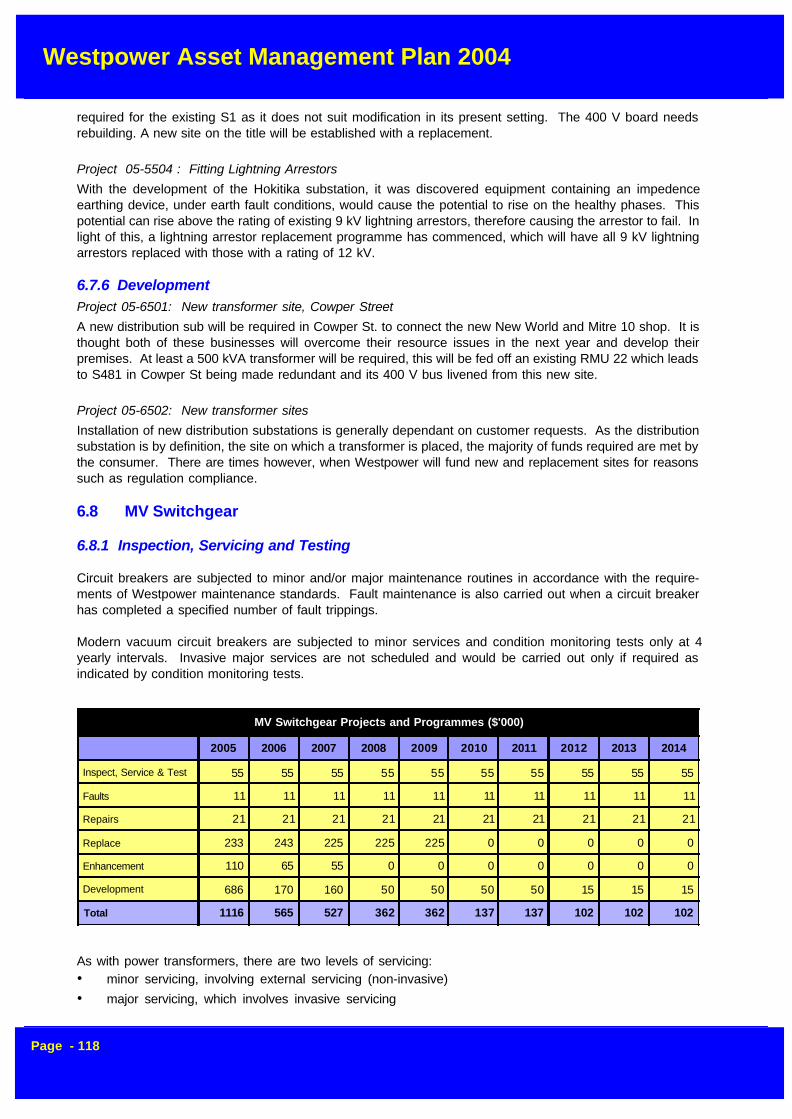
Westpower Asset Management Plan 2004
Page - 118
required for the existing S1 as it does not suit modification in its present setting. The 400 V board needsrebuilding. A new site on the title will be established with a replacement.
Project 05-5504 : Fitting Lightning Arrestors
With the development of the Hokitika substation, it was discovered equipment containing an impedenceearthing device, under earth fault conditions, would cause the potential to rise on the healthy phases. Thispotential can rise above the rating of existing 9 kV lightning arrestors, therefore causing the arrestor to fail. Inlight of this, a lightning arrestor replacement programme has commenced, which will have all 9 kV lightningarrestors replaced with those with a rating of 12 kV.
6.7.6 DevelopmentProject 05-6501: New transformer site, Cowper Street
A new distribution sub will be required in Cowper St. to connect the new New World and Mitre 10 shop. It isthought both of these businesses will overcome their resource issues in the next year and develop theirpremises. At least a 500 kVA transformer will be required, this will be fed off an existing RMU 22 which leadsto S481 in Cowper St being made redundant and its 400 V bus livened from this new site.
Project 05-6502: New transformer sites
Installation of new distribution substations is generally dependant on customer requests. As the distributionsubstation is by definition, the site on which a transformer is placed, the majority of funds required are met bythe consumer. There are times however, when Westpower will fund new and replacement sites for reasonssuch as regulation compliance.
6.8 MV Switchgear
6.8.1 Inspection, Servicing and Testing
Circuit breakers are subjected to minor and/or major maintenance routines in accordance with the require-ments of Westpower maintenance standards. Fault maintenance is also carried out when a circuit breakerhas completed a specified number of fault trippings.
Modern vacuum circuit breakers are subjected to minor services and condition monitoring tests only at 4yearly intervals. Invasive major services are not scheduled and would be carried out only if required asindicated by condition monitoring tests.
As with power transformers, there are two levels of servicing:• minor servicing, involving external servicing (non-invasive)
• major servicing, which involves invasive servicing
MV Switchgear Projects and Programmes ($'000)
2005 2006 2007 2008 2009 2010 2011 2012 2013 2014
Inspect, Service & Test 55 55 55 55 55 55 55 55 55 55
Faults 11 11 11 11 11 11 11 11 11 11
Repairs 21 21 21 21 21 21 21 21 21 21
Replace 233 243 225 225 225 0 0 0 0 0
Enhancement 110 65 55 0 0 0 0 0 0 0
Development 686 170 160 50 50 50 50 15 15 15
Total 1116 565 527 362 362 137 137 102 102 102

Westpower Asset Management Plan 2004
Page - 119
The frequency and scope of servicing is defined uniquely for each type, make and model of circuit breaker,and costs per breaker vary significantly. Typically, minor servicing is carried out annually, depending on typeat a cost ranging from a few hundred dollars to $1,000 per service. While major servicing, is typically under-taken every 2 to 10 years at a cost of $1,500 to $5,000 per service. There are breaker types that lie outsideof these ranges both for frequency of service and service cost.
The annualised servicing cost averages around $950 per year per breaker for outdoor circuit breakers andaround $305 per year per breaker for indoor metalclad switch gear.
6.8.2 Fault Repairs
6.8.2.1 Circuit Breakers
Fault repairs to switchgear take place as required, but as the population of older bulk-oil reclosers diminishesin line with the circuit breaker replacement programme, the occurrence of these faults has been greatlydiminished.
Failures in indoor switchgear are also relatively rare, but with the increasing age profile of this equipment, itis expected that the fault rate will begin to increase within the next five years. A case in point is the YorkshireSO-HI switchgear at Greymouth Substation that was replaced in 2002 because of the risk of failure.
6.8.2.2 Disconnectors
Disconnectors normally fail due to deterioration of the operating arms with corrosion or from an arc develop-ing across two or more phases. By identifying under-rated disconnectors and replacing these, the incidenceof arcing faults should be reduced.
6.8.3 Planned Repairs and Refurbishment
6.8.3.1 Circuit Breakers
Planned repair work in respect to circuit breakers would be additional corrective work and refurbishmentidentified during routine services, inspections and tests or following failures. Refurbishment work plannedincludes overhaul of decommissioned circuit breakers prior to placing in stores
This work amounts to an average of $5,000-$8,000 pa.
In addition, general corrective work arising out of defects identified from routine service inspections and testswill lead to an expected total cost of $11,000 pa.
6.8.4 Replacement Programmes
Westpower has determined its replacement programme for high voltage switchgear based on the followingcriteria:
(i) Safety
Where equipment presents a higher than normal risk to personnel during operating or maintaining the equip-ment e.g• generic types of aged bulk oil circuit breakers with history of failures• circuit breakers requiring hand closing

Westpower Asset Management Plan 2004
Page - 120
(ii) Technical Suitability
This applies to equipment that is no longer suitable for its service application e.g.• disconnectors and circuit breakers unreliable or inconsistent in performing their functions due to
excessively worn mechanisms• equipment which fails to meet Westpower’s seismic requirements• under-rated equipment
(iii) Economics
This is where replacement is justified purely for economic reasons, e.g.• equipment is excessively expensive to maintain or repair• high cost of spares or where spares can no longer be purchased
• maintenance intensive equipment installed at a sensitive supply location
6.8.4.4 Circuit Breakers - Outdoor
In line with the practice of overseas utilities as reported by CIGRE, Westpower has a policy, subject toproject-specific economic analysis, of replacement rather than life extension of aged deficient bulk oil andminimum oil circuit breakers by major refurbishment.Circuit breakers are also replaced for the following reasons
• where they have high maintenance costs• where they are unreliable due to an increased defect rate
Where a system node requires a maintenance free circuit breaker i.e. maintenance outages cannot be toler-ated.
MV Switchgear Projects ($'000)
Area 2005 2006 2007 2008 2009 2010 2011 2012 2013 2014
05-5601 E Automate XD21 Inchbonnie ALD4 18 0 0 0 0 0 0 0 0 0
05-6601 D Install Regulator Haupiri Area ALD4 120 0 0 0 0 0 0 0 0 0
05-6602 D Install Load Equalising Recloser at Inchbonnie ALD4 10 0 0 0 0 0 0 0 0 0
05-5602 E Automate Disconnector AK1, Arahura DIL4 10 0 0 0 0 0 0 0 0 0
05-5603 E Automate FF14 Fox Glacier FOX1 16 0 0 0 0 0 0 0 0 0
05-6603 D Franz Josef 11 kV Ring - RMU Automation FRZ1 50 0 0 0 0 0 0 0 0 0
05-4601 RPL Replace 11 kV links with disconnector South Waiho FRZ3 8 0 0 0 0 0 0 0 0 0
- E Relocate RW17T, Trickies Road GYM11 0 10 0 0 0 0 0 0 0 0
05-4602 RPL Ring Main Unit Replacement GYM13 75 75 75 75 75 0 0 0 0 0
- RPL Ruatapu switchyard rationalisation HKK10 0 18 0 0 0 0 0 0 0 0
05-6604 DSouth Westland Potential Support (SWPS) HarihariRegulator
HKK1012 300 0 0 0 0 0 0 0 0 0
05-5605 E Fit Earth Fault Indicators to RMU's SYS 15 15 15 0 0 0 0 0 0 0
05-5604 E Upgrade L27, Myers Mill SYS 15 0 0 0 0 0 0 0 0 0
05-4603 RPL Disconnector Replacements SYS 80 80 80 80 80 0 0 0 0 0
05-6605 D New Disconnectors SYS 15 15 15 15 15 15 15 15 15 15
05-5606 E Disconnector Automation General SYS 36 40 40 0 0 0 0 0 0 0
05-6607 D Install Ring Main Units - Unspecified Locations SYS 35 35 35 35 35 35 35 0 0 0
05-6606 D Install Capacitors at Various locations SYS 156 120 110 0 0 0 0 0 0 0
05-4604 RPL KFE Recloser replacement at Zone Substations SYS 70 70 70 70 70 0 0 0 0 0
Total 1029 478 440 275 275 50 50 15 15 15

Westpower Asset Management Plan 2004
Page - 121
It is internationally recognised that forty years is generally the “time expired” life of circuit breakers. Sometypes have an economic life greater or less than this figure. Bulk oil breakers generally have a longer life,while minimum oil breakers typically last only 30-35 years.
While age is not itself criteria for replacement, analysis based on likely total economic lives for each type,make and model of circuit breaker provides a means of assessing likely future replacement requirements.The replacements themselves would be determined by safety, economics and reliability assessments at thetime.
Many of the existing older bulk-oil reclosers have been replaced with modern, low-maintenance vacuumbreakers.
The continuing replacement programme for outdoor circuit breakers, has resulted in there being no breakersover 25 years of age.
6.8.4.5 Andelect Units
Westpower has experienced two serious failures of Series I versions of these oil switch units during routineoperation and they are considered to constitute a serious health and safety risk. A replacement programmehas been instituted to gradually replace all these units over the next four years. In the meantime, strictoperational procedures are being brought into force to mitigate the risk to operators of the equipment underthe particular circumstances.
Project 05-4601: Replace 11 kV links with disconnector South Waiho
The dairy expansion South of the Waiho River has rendered the 11 kV links at site FF26 inadequate as anisolation device. These links will be removed and a disconnector is to be installed at the same site. This willprovide three phase switching for this section of line.
Project 05-4602 Ring Main Unit Replacement
The Andelect Series 1 ring main units have come to the end of their economic life, as well some authoritiesconsider these to be a health and safety risk. They will be progressively removed from Westpower’s networkwith two a year being targeted. In 2004/2005 the two at Moana will be replaced. In 2005/2006 the GreymouthCourt House and RMU 5 at the base of Arnott’s Heights will be replaced. There will be an ongoing programmeto replace the rest.
Project 05-4603 Disconnector Replacements
Disconnectors normally fail due to deterioration of the operating arms with corrosion or from an arc develop-ing across two or more phases. By identifying under-rated disconnectors and replacing these, the incidentsof arcing faults should be reduced.
Project 05-4604 KFE Recloser replacement at Zone Substations
KFEs are starting to give variable performance in zone substations. Their settings selection is limited. It isproposed that as their setting limitations are identified as to cause nuisance they are to be replaced progres-sively with KFME/FXB or 351 combinations. The removed reclosers are then held for replacements of failedunits or put in less onerous positions in rural parts. It is proposed to change out the two NGH and one WATreclosers in the next year as their set-ability is not ideal and the protection replacement will lend with thegeneral communications upgrade to the site. One of the Ngahere reclosers also has an earlier version ofautomation that has not worked ideally. Two removed KFE’s will be reused at less important sites, one will beheld as spare, there are no spare KFE’s at present.
6.8.5 Enhancements
Several reclosers and sectionalisers (circuit breakers used to isolate faults on rural lines) are reaching theend of their economic life and are becoming unreliable. This results in prolonged and more widespread

Westpower Asset Management Plan 2004
Page - 122
power outages than necessary during fault conditions.
It is no longer possible to source replacement parts for many of these units and because of the bulk oil designof the earlier models, the maintenance costs will increase significantly.
It is proposed that the older models of reclosers and sectionalisers be replaced over the next two years.
Project 05-5601: Automate XD21 Inchbonnie
A number of faults occur on the spur toward Kumara from Inchbonnie. It is proposed to install an actuatorand automate XD21 so automatic clearance of this spur can occur following a fault.
Project 05-5602: Automate Disconnector AK1, Arahura
To aid fault response AK1 shall be automated to allow the area North of the ElectroNet depot to be restoredpromptly. Though this is close to fault people, they are often on other calls when AK1 needs to be openedthen AA10T closed to re-liven Arahura after a fault over the Blue Spur or to put L8 back on from the North fora fault in the Kaniere area. No FPI will be required, the disconnector is new so site works will be minimal.
Project 05-5603: Automate FF14 Fox Glacier
To aid fault response FF14 should be automated to allow the area south of Fox Glacier to be restored forfaults south of FF14. At present it takes a minimum of 1.5 hours for a fault person to respond, a minimum of0.4 SAIDI will be saved each time it is operated.
Project 05-5604: Upgrade L27, Myers Mill
Kopara is a site of regular faults with a large number recorded over the past few years. At present a fault atKopara requires interruption of the fault to occur by ALD CB4. The project entails upgrading L27 sectionaliserto a recloser and will allow for only Kopara to be interrupted in the occurrence of a fault. This project willimprove the SAIDI figures.
Project 05-5605: Fit Earth Fault Indicators to RMU's
A new type of fault passage indicator is being evaluated by ENS. If it proves suitable they should be fitted toall unprotected cables to detect current passage due to a fault down them. These will allow fault people toquickly identify a faulty cable to speed its isolation and prompter restoration of the feeder.
Project 05-5606: Disconnector Automation General
To aid faster restoration of load in remote areas the use of automated disconnectors have proved invaluable.Various remote areas are targeted to have their disconnectors automated. On occasion the disconnectorsare found to be of the old brown type and not suitable for automating.
6.8.6 Development
Reclosers are pole-mounted circuit breakers, which automatically isolate a faulted section of the line from therest of the network. Where a large radial network exists, reclosers are often fitted on spur lines to prevent themain line from tripping out due to a spur fault. The addition of extra reclosers to the network improves systemreliability and fault selectivity. Justification of each project is carried out on a case by case basis.
Supply to the West Coast in general is voltage constrained and this is partly due to the long inductive trans-mission lines. When a line outage occurs due to fault or planned maintenance events, voltage collapse canoccur unless significant support is available from local generation; this in turn may depend on water availabil-ity.
Investigations are continuing with Transpower on the need for further reactive voltage support on the WestCoast and the most efficient way of providing this.
Westpower Asset Management Plan 2004
Page - 123
Project 05-6601: Install Regulator, Haupiri Area
Kopara is experiencing unacceptable voltage variation with system loading variations. To ensure an accept-able supply, two single-phase voltage regulators are to be installed after L27. The regulators will be installedas an open delta configuration as to provide three-phase voltage regulation. In addition 300 kVA capacitorsare to be installed, with 5.5% blocking chokes, before the regulator. This is to provide the necessary voltagesupport during increased system loadings.
Project 05-6602: Install Load Equalising Recloser at Inchbonnie
Inchbonnie and Rotomanu’s supplies have become constrained due to an increase in dairy load over thepast few years. Capacitors are to be installed on the Rotomanu side to provide voltage support to the area.This project entitles installing a load equalising recloser to replace DH18T, enabling Inchbonnie to utilisevoltage support from the Rotomanu capacitors while avoiding excessive low load voltage rise.
Project 05-6603: Franz Josef 11 kV Ring - RMU Automation
When the FRZ 11 kV ring was installed it was not possible to automate the new RMU’s. Once a local radiolicense is gained, this project can be completed to give remote control of the RMU’s to speed the restorationof the Franz CBD for a cable fault.
Project 05-6604: South Westland Potential Support (SWPS) Harihari Regulator
The South Westland system potential could be augmented by installing a 33 kV regulator at Harihari in theline south to Whataroa. This will delay the need for 66 kV to be extended to South Westland by a few years.
Project 05-6605: New Disconnectors
Several new disconnectors are to be installed to further sectionalise the network and reduce the number ofcustomers affected by 11 kV switching operations. These disconnector installations will also assist in thelocating of faults.
Project 05-6606: Install Capacitors at Various locations
It is intended to continue to install capacitor banks in the rural distribution to provide local voltage support.It is proposed to install capacitors, the sizes below are an indication only, at:
- Kokatahi, 1 Mvar 11 kV fixed, this was planned for 2003/2004 – the capacitors were diverted to aSolid Energy Site – some of the work has already been carried out – estimated outstanding cost$18k
- Inchbonnie area, 0.5 Mvar bank, a modular 400 V system – estimated cost $60k
- Atarau, a 0.5 Mvar 11 kV fixed cap with 5% choke – estimated cost $26k
- Taramakau Settlement, a 0.5 Mvar 11 kV fixed cap with 5% choke – estimated cost $26k
- Ikamatua, a 0.5 Mvar 11 kV fixed cap with 5% choke – estimated cost $26k2005/2006 – $120k total
- South Westland, 0.5 Mvar bank, a modular 400 V system probably at Wahapo Zone Sub – estimatedcost $60k
- Haupiri, up to 0.5 Mvar bank, a modular 400 V system possibly at the Christian Community pendingtheir assistance – estimated cost $60k.2006/2007 – $110k total
- South Westland, up to 0.5 Mvar bank, a modular 400 V system possibly at the Fox Zone Sub –estimated cost $60k.

Westpower Asset Management Plan 2004
Page - 124
- Greymouth, a 2 of 1.0 Mvar 11 kV fixed cap with 5% choke – possibly use Ferguson Bros. bunker to housethese – this would be in reaction to IPL expanding or Transpower demanding more reactive support – estimated cost $50k
Project 05-6607: Install Ring Main Units - Unspecified Locations
Often a developer requires a new supply which includes the need for a RMU. An allowance is being made forone site to meet this unplanned demand.
6.9 SCADA, Comms and Protection
6.9.1 Periodic Inspections, Servicing and Testing
6.9.1.1 SCADA System
The integrity of the main hardware and software system at the control room is of the highest importance tothe ongoing management and safety of the grid network. Westpower’s Asset Management staff manage thecomputer system and maintain the operational state of the software and hardware systems. This is a 24-hour per day task with staff on call if required to ensure high availability of equipment. The main computerhardware and software are protected by a maintenance contract with the supplier.
An approved contractor will manage all communication and SCADA equipment external to the computersystem. This provides for continuous maintenance and fast response for fault repairs.
6.9.1.2 Communications
Every asset is to be inspected six-monthly, and serviced on an annual basis. The six-monthly inspection is,as far as possible, non-intrusive. No adjustments are made until items are out of tolerance, or performanceis affected.
Antenna support structures, e.g. wood poles, towers, and monopoles are inspected two or three yearly.
Antennae are to be checked annually with a “Bird” RF wattmeter.
6.9.1.3 Protection
The policy in this area is to maintain protection schemes with alternate major and minor services every 2years, on each circuit.
SCADA, Comms and Protection Projects and Programmes ($'000)
2005 2006 2007 2008 2009 2010 2011 2012 2013 2014
Inpect, Service & Test 62 37 37 37 37 37 37 37 37 37
Faults 19 19 19 19 19 19 19 19 19 19
Repairs 13 13 13 13 13 13 13 13 13 13
Replace 102 30 380 30 0 0 0 0 0 0
Enhancement 202 25 135 0 0 0 0 0 0 0
Development 110 150 0 0 0 0 0 200 0 0
Total 508 274 584 99 69 69 69 269 69 69

Westpower Asset Management Plan 2004
Page - 125
It should be noted that “maintenance” on protection equipment is essentially “recalibration/testing” ratherthan the conventional view of maintenance, which would imply replacement of consumable parts. Protectionmaintenance is mainly required to reaffirm that the protection is calibrated within tolerance and will operatewhen called upon to do so.
There are international trends towards reduced maintenance. Typically intervals are being increased tobetween 3 and 4 years in other utilities comparable to Westpower, in particular where microprocessor (nu-merical) protection systems are used. These protections have in-built self testing and monitoring routineswhich reduce the necessity for manually driven maintenance testing.
A new fully-automated protection relay test set is being introduced to facilitate maintenance testing. This willbe used for commissioning of new protection (developments and enhancements) as well as maintenance.
6.9.2 Planned Repairs and Refurbishment
6.9.2.1 Communications
Westpower maintains communications assets at approximately 28 base sites and on 5 repeater sites. Theplanned repair and refurbishment estimates are based on past expenditure.
Contract maintenance technicians are expected to respond to approximately 12 faults per annum.
6.9.2.2 Protection
The protection expenditure planned over the review period is mainly in the following areas• replacement of outdoor junction boxes
• replacement of aged feeder protection and controls• replacement of lead acid batteries with sealed cells• seismic strengthening of protection panels• seismic restraints for batteries• installation of DC monitoring and distribution panels
Project 05-1701: Replace UHF/VHF aerial assembly Tainui Street
The existing UHF/VHF aerial assembly at the Tainui Street depot is difficult to maintain because of restrictedaccess. It is not possible to climb the existing antenna mast, and long reach epv’s need to be used. As acritical part of Westpower’s important emergency response communications system, this mast will be up-graded to the same standard of other antenna masts at the Tainui Street depot.
Project 05-1702: Procurement South Westland UHF Spares
The analogue UHF equipment that will be released from service as a result of the Digital UHF upgradeproject in the northern area will be used to extend the life of the exsting analogue UHF radio equipment inSouth Westland.
6.9.3 Replacement Programmes
6.9.3.1 Communications
Communications equipment has in general a shorter life expectancy than heavy electrical equipment. Typi-cally electronic equipment reaches technical obsolescence in 5-10 years although generally the equipmentcan be supported in service for 10-15 years. Westpower has 1 power line carrier (PLC) system that is 16years old, however, this is likely to be retired from service when the new digital UHF radio network betweenGreymouth and Kumara is commissioned in 2004.

Westpower Asset Management Plan 2004
Page - 126
6.9.3.2 SCADA
As with all computer-based systems, it is expected that several upgrades of the operating system, software-applications and hardware will be required throughout the planning period.
Project 05-4701: SCADA Master Station Replacement
The existing SCADA Master Station has been in service, albeit with several upgrades, since 1994 and is nowbeginning to lag behind the functionality of modern systems. It is recommended that the current system beupgraded to the latest windows based version, giving more modern functionality and extending the life of thecurrent system.
Project 05-4702: Replace RTU units
With the extensive use of Abbey RTU's the licence range needs to be extended. Also, as new protectionrelays are fitted to Westpower substations the current dataterms are not capable of communicating the newinformation, It is important that new RTU's need to be purchased and commissioned.
6.9.4 Maintenance Summary
The table at the beginning of this section summarises expected system maintenance expenditure.
6.9.5 Enhancement
There are several small upgrade jobs planned for the SCADA, Communication and Protection systemsthroughout the planning period
6.9.5.1 Remote Controlled Disconnectors
With the advent of industry-wide performance monitoring, Westpower is now being benchmarked againstother Electricity Companies in terms of system reliability and continuity of supply. Furthermore, customersare becoming more aware of fault outages, this being partly due to the increase in the number of electronichome appliances and the resulting reliance on a continual supply of electricity. For these reasons, it isbecoming increasingly important to cut down on fault restoration times.
One way to do this is by automating remote air break switches. This greatly reduces the travelling timerequired for a faultman during sectionalising of faulted line sections. This also means that fewer staff arerequired to isolate the fault, reducing the overall cost of fault restoration.
SCADA, Comms Protection Projects ($'000)
Area 2005 2006 2007 2008 2009 2010 2011 2012 2013 2014
05-6702 D New Repeater, Mt Kakawau SYS 2 0 0 0 0 0 0 0 0 0 0
05-6703 D UHF at Whataroa and Wahapo SYS 3 0 0 0 0 0 0 0 0 0 0
05-6701 D UHF Digital Radio, Grey Valley SYS 6 0 1 5 0 0 0 0 0 0 0 0 0
- D VHF Digital Radio, South Westland SYS 0 0 0 0 0 0 0 2 0 0 0 0
05-5701 E Front end comms processor SYS 1 2 0 0 0 0 0 0 0 0 0
05-5702 E Protection upgrades SYS 1 6 0 2 5 1 0 5 0 0 0 0 0 0 0
E SCADA for protection upgrade SYS 0 0 3 0 0 0 0 0 0 0 0
05-5703 E Upgrade Generator for UPS at Greymouth SYS 3 0 0 0 0 0 0 0 0 0 0
05-1702 I Purchase South Westland UHF Spares SYS 1 0 0 0 0 0 0 0 0 0 0
05-1701 I Replace UHF/VHF aerial assembly Tainui Street SYS 1 5 0 0 0 0 0 0 0 0 0
05-4702 RPL Replace RTU Units SYS 3 2 3 0 3 0 3 0 0 0 0 0 0 0
04-4701 RPL SCADA Master Station Replacement SYS 7 0 0 3 5 0 0 0 0 0 0 0 0
Total 4 3 9 2 0 5 5 1 5 3 0 0 0 0 2 0 0 0 0
Westpower Asset Management Plan 2004
Page - 127
Project 05-5701: Front end comms processor
With the introduction of IP over the UHF digital radio to Westpower's major substations, a communications IOserver to interface between the field equipment and SCADA HMI was required. Currently this comms serveris located in the control room. This device has now become mission critical and now requires a fail overdevice. Also required for this project is a smart IP switch to monitor IP traffic on the radio network.
Project 05-5702: Protection upgrades
Cooper Form 4C and 3A controllers are coming to the end of their economic life. Below is a plan to replacethe rest of these and then address the ageing GEC electromechanical and ASEA Combiflex range of equip-ment.
2004/2005 – $190k total- DOB controller replacements, three 4C’s (install SEL 311C) and one 3A (install SEL 351A) to replace
estimated cost $100k.- RAP one 3A controller and GEC protection replacements, install three SEL 351 – estimated cost
$50k.- WAH controller replacement, one 4C (install SEL 351R ex HKK) – estimated cost $5k- NGH one 3A controller install the prototype SEL 351A – estimated cost $5k.2005/2006 – $225k total- KUM – carry out planning and design for protection upgrade. Estimated cost $20k.- DIL – carry out planning and design for protection upgrade. Estimated cost $5k.2006/2007 – $105k total- KUM – carry protection upgrade. Estimated cost $90k.- DIL – carry out protection upgrade. Estimated cost $15k.
Project 05-5703: Upgrade Generator for UPS Greymouth to 20 kVA
The generator which syncronizes automatically with the UPS system at the Greymouth depot has proved tobe unreliable due to voltage distortion at the UPS. Recent investigation undertaken by Vectek Electronicsdiscovered the current generators capacity was insufficient for the existing load. The rule of thumb is to havea generator which is capable of an output of three times the UPS rating. With this in mind, it has beenrecommended a 20 kVA generator be installed to replace the 5 kVA currently in use. This will ensure asecure power supply can indefinitely be provided to the control room and other critical points in the case of apower outage. or emergency.
6.9.6 Development
Digital UHF Radio System
Development of SCADA, Comms and Protection assets normally take place in conjunction with a majorsubstation development.
The construction of a major new substation at Hokitika and the pending construction of a similar substation atReefton caused Westpower to review the communications infrastructure supporting these new assets.
A number of changes in technology over recent years means that most equipment manufacturers are adopt-ing standard interfaces such as Ethernet IP (Internet Protocol) for their equipment. This is a standard plat-form allowing multiple equipment types to coexist on the same communications backbone and provide forenhanced diagnostic and monitoring functions required. In addition, protection relay signaling over commu-nications channels, which Westpower is now required to use for the first time for these new substations,requires high integrity digital data links.
The existing analogue UHF system is not capable of handling the additional scope and type of data trafficrequired.
Westpower Asset Management Plan 2004
Page - 128
As much of the existing UHF radio equipment is now over fifteen years old and reaching the end of it’seconomic life, a decision was made to embark on a replacement program that will see the existing equipmenttotally replaced with Exicomm 64K Digital UHF radio links.
Stage 1 of the project covering the repeater at Paparoa and bases at Greymouth, Hokitika, Kumara andDobson was completed by the end of third quarter of 2003.
Project 05-6701: UHF Digital Radio, Grey Valley
This project will see the completion of stage 2 of the digital radio rollout by October 2004. Once completedIP will be available in Hokitika, Kumara, Rapahoe, Ngahere, Arnold and Reefton.
Project 05-6702: New Repeater, Mt Kakawau
For several years, Westpower has been using it's existing VHF speech radio channels to provide SCADAcommunications facilities to outlying areas. While this has worked well, and made efficient use of existingchannel capacity, the number of Remote Terminal Units (RTU's) connected to the system has increasedrapidly over recent times as a result of Westpower's Distribution Automation Programme and the situationhas now reached the stage where a separate VHF SCADA channel is warranted.
Project 05-6703: UHF at Whataroa and Wahapo
To extend the life of the current UHF radio link into South Westland it is recommended Westpower install newRTU's in Whataroa and Wahapo substations and move all the UHF Radio equipment from the Railtech siteinto the BCL site.
6.10 Distribution Transformers
The population of distribution transformers covers a diverse range of sizes, types and ages. As such, it isimportant that a comprehensive management plan is put in place, as the condition of the asset is not alwayseasily discernible on an overall basis.
Westpower’s policy is to extend the life of distribution transformers where this is economically feasible. Insupport of this policy, many distribution transformers run well below their rated values for much of the timeresulting in long lives for the cores and windings. Provided that the tanks and oil is well maintained the overallunit may be kept in service for up to 55 years. In this way, the maximum return can be leveraged from thesehigh value assets.
6.10.1 Maintenance
6.10.1.1 Routine Patrols and Inspections
Smaller pole-mounted distribution transformers are regularly inspected on a rolling five-year basis in con-junction with Westpower’s substation earth testing programme.
The inspection includes checks for
• tank corrosion• paint chips• breakdown• oil leaks
• insulator damage• breather condition• termination faults
Where possible, the oil level is checked and recorded, and if an oil sample valve is available (standard issue

Westpower Asset Management Plan 2004
Page - 129
on all new transformers), a sample of the oil is taken and checked for dielectric breakdown.
Larger pole-mount and all pad-mount units have Maximum Demand Indicators (MDI’s) which are read everyquarter. These indicate loading trends to be monitored and allow for early intervention should a unit becomeoverloaded.
Very large transformers in areas such as the CBD of Greymouth and Hokitika have annual thermographsurveys carried out to check the tank and termination temperatures as well as to identify any other potentialhotspots. Any indications suggesting that the transformer requires attention results in prompt on-site repairs,or if this is not possible, the transformer is swapped with a spare unit from the store and sent back to thecontractor’s workshop for refurbishment.
Project 05-1802: General Transformer Servicing
Current levels of transformer servicing will be maintained including oil treatment and tank repairs as required.Westpower’s policy is to extend the life of distribution transformers as long as this is technically and economi-cally feasible and has arranged for its nominated contractor to supply appropriate workshop facilities inGreymouth to complete this work.
Project 05-1801: Refurbish ETEL, ABB & Tolley Transformers
A major gasket and bushing replacement programme will be continued to manage the unnacceptable failurerisk represented by the premature gasket failure problem identified with these transformers.
6.10.1.2 Faults
The majority of faults are caused by lightning damage; it is very rare for a unit to fail because of old age ordeterioration because of the regular inspection and servicing carried out. (It is likely that the level of faultswould be much higher but for Westpower’s policy of fitting lightning arrestors to all substations)
Most faults are handled by swapping the transformer with a spare and sending the damaged unit back to thetransformer workshop for inspection and repair - or scrapping if the damage is too severe.
An exception to this is bushing faults on large units where the bushing can be easily repaired or replaced onsite.
6.10.1.3 Repairs and Refurbishment
Repairs can range from a minor paint touch-up on earlier painted units through to insulator repairs and boltreplacements. Refurbishment may include oil changes, rewinds and even tank replacements.
Rewinds are only attempted on relatively modern units where modular replacement windings are readilyavailable.
Tanks are often subject to corrosion, especially in the case of older painted units. At the same time however,the internal core and windings may be in excellent condition. For this reason, tanks are often repaired orreplaced if the unit is otherwise in good condition.
Each unit is assessed on its age, condition and service history in determining whether to repair or replace theunit.
Transformer Gasket Issues
Further difficulties with gasket erosion, followed by a lack of satisfactory progress from our small transformersuppliers, led to a full investigation being carried out into this problem in conjunction with Industrial Researchto try and determine the exact failure mechanism. What was initially thought to be a partial discharge prob-lem turned out to be related to leakage current along the outside of the bushing, This leakage current in-

Westpower Asset Management Plan 2004
Page - 130
creases markedly when exposed to salt fog conditions, as commonly experienced on the West Coast of theSouth Island.
A number of measurements were taken in a test environment and a viable mechanism that explains thegasket erosion problem was developed. Interestingly, the zinc-rich paint that had been applied as an interimmeasure was found to be of little practical value as the paint was not particularly conductive and a new,conductive paint is now being used in the interim. Notwithstanding this, paint is likely to wear off over time,only stalling any deterioration rather than overcoming the problem.
The best long term solution identified has been to source an 11 kV bushing with a semi-conductive coatingfrom the flange, where it interfaces with the tank gasket, down to the internal thread where the securing nutis fitted. This provides a parallel low-impedance path for any leakage current away from the exposed gasketedge and should permanently overcome the problem.
Westpower is currently working with bushing suppliers and gasket manufacturers to provide a suitable bush-ing, and this is not expected to be difficult as the coating technology sought is already used on 22 kV andhigher voltage bushings.
Once a suitable bushing is found, this will be specified for all future transformer supplies and a long termreplacement programme will be instituted to upgrade the existing population of transformers; particularlythose at-risk units in the vicinity of the sea coast.
Distribution Transformer Projects and Programmes ($'000)
2005 2006 2007 2008 2009 2010 2011 2012 2013 2014
Inpect, Service & Test 257 257 257 257 257 207 207 207 207 207
Faults 10 10 10 10 10 10 10 10 10 10
Repairs 0 0 0 0 0 0 0 0 0 0
Replace 50 50 50 50 50 50 50 50 50 50
Enhancement 0 0 0 0 0 0 0 0 0 0
Development 400 400 400 400 400 400 400 400 400 400
Total 717 717 717 717 717 667 667 667 667 667
Distribution Transfomers Projects ($'000)
ID Act Description Area 2005 2006 2007 2008 2009 2010 2011 2012 2013 2014
05-6801 D Purchase of new transformers SYS 400 400 400 400 400 400 400 400 400 400
05-1802 I General Transformer Servicing SYS 90 90 90 90 90 90 90 90 90 90
05-1801 I Referbish ETEL, ABB & Tolley Transformers SYS 50 50 50 50 50 0 0 0 0 0
05-4801 RPL Transformer Replacements SYS 50 50 50 50 50 50 50 50 50 50
590 590 590 590 590 540 540 540 540 540

Westpower Asset Management Plan 2004
Page - 131
6.10.1.4 Replacement
Project 05-4801: Transformer replacement
Very old transformers that require extensive refurbishment or transformers that have been extensively dam-aged due to say lightning damage are often replaced rather than repaired. This is a purely economic deci-sion.
All replacement units are purchased to Westpower’s purchasing specifications, which prescribe galvanisedtanks, stainless steel fixings and oil sampling valves to minimise the cost of future maintenance.
6.10.2 Enhancement
Little enhancement work is carried out on distribution transformers, as these are essentially a standardmodule with no capacity for upgrading.
Occasionally duplex arcing horns may be fitted to existing units where lightning arrestors can not be used.
6.10.3 Development
New units are purchased to Westpower’s purchasing specifications as required. These are normally re-quired for new loads remote from Westpower’s existing reticulation network and are paid for by the customeror developer.
Independent contractors installing new substations for customers may provide new units and hand themover to Westpower on commissioning provided that test results are satisfactory.
6.11 Other
Westpower’s three in-service ripple injection plants are all of the same make and model (Plessey TR series)making lifecycle management easier to implement.
Other Projects and Programmes ($'000)
2005 2006 2007 2008 2009 2010 2011 2012 2013 2014
Inspect, Service & Test 15 15 15 15 15 15 15 15 15 15
Faults 5 5 5 5 5 5 5 5 5 5
Repairs 15 15 15 15 15 15 15 15 15 15
Replacement 0 0 0 0 0 0 0 0 0 0
Enhancement 0 0 0 0 0 0 0 0 0 0
Development 0 0 0 0 0 0 0 0 0 0
Total 35 35 35 35 35 35 35 35 35 35
Westpower Asset Management Plan 2004
Page - 132
6.11.1 Maintenance
6.11.1.1 Routine Patrols and Inspections
Monthly checks are carried out as part of regular Zone Substation visits which include the visual inspectionsof the• converters• coupling transformers• coupling cells• GPS time base receivers
Every three years independent experts determine injection levels, current balance, optimum tuning and loadsharing with other units carry out a full inspection.
6.11.1.2 Faults
The solid state construction of the injection plants, and the fact that they operate well below their maximumpower levels, means that faults are very rare.
On rare occasions the high-power output transistors may require replacement or the logic board may requirerepair.
At other times, vermin may get into the high voltage coupling cells causing flashover.
The redundancy built into the injection network means that the failure of any single plant will not severelyimpact on overall ripple signal propagation and faults are able to be handled without undue time pressure onrestoration.
6.11.1.3 Repairs and Refurbishment
Minor repairs are required on the coupling equipment and converters from time to time as a result of faultevents.
There is no planned repair and refurbishment program planned for this equipment which is relatively youngand in good condition. It is expected that the plants will give at least ten years of trouble-free service.
6.11.1.4 Replacement
No replacements are foreseen within the planning period.
6.11.2 Enhancement
The capacity of the existing equipment is fixed and provides ample room for network expansion. No en-hancement work is planned.
6.11.3 Development
No new plants are expected to be required for the foreseeable future however allowance has been made forunspecified development projects that ultimately turn up and require inclusion into the Asset ManagementPlan.

Westpower Asset Management Plan 2004
Page - 133
7.0 FINANCIAL SUMMARY
7.1 Financial Forecasts
Table 7.1a below shows the projected ten-year asset management plan expenditure, by asset type and byactivity.
These tables have been built up from the individual project and programme expenditures developed in Sec-tion 6 – Lifecycle Management Plan, and demonstrate a generally falling expenditure over the duration of theplanning period.
Table 7.1a – Asset Management Plan Expenditure
It should be noted that the estimates for the first half of the planning period are based on known drivers andhence are more accurate than those for the second half which are more in the nature of educated guessesdue to a large number of unpredictable factors. Furthermore, in developing these figures, Westpower hashad several years of experience in budgeting and controlling this expenditure and there is a high degree ofcertainty in the values.
Summary by Activity
2005 2006 2007 2008 2009 2010 2011 2012 2013 2014
Inspection, Service & Testing 2290 2352 2286 2111 2132 1948 1903 1888 1878 2078
Faults 293 293 293 293 293 293 293 293 293 293
Repairs 191 175 175 175 175 175 175 175 175 175
Replace 1477 1790 1610 887 668 120 100 50 50 50
Enhancement 1300 905 780 500 180 60 60 0 0 0
Development 6031 6541 2775 720 3465 565 565 1525 475 475
Total 11583 12057 7920 4687 6914 3162 3097 3932 2872 3072
Summary by Asset Type
2005 2006 2007 2008 2009 2010 2011 2012 2013 2014
Subtransmission 1471 2532 2657 497 1168 320 275 580 230 230
Distribution 3093 2648 2062 1762 1563 1180 1160 1130 1130 1130
Reticulation 301 295 236 113 93 87 87 87 87 87
Services 133 133 133 133 133 133 133 78 78 78
Zone Substations 3611 4362 413 513 2408 168 168 678 168 368
Distribution Substations 608 506 566 466 376 376 376 316 316 316
MV Switchgear 1116 565 527 362 362 137 137 102 102 102
SCADA, Comms, Protection 508 274 584 99 69 69 69 269 69 69
Distribution Transformers 717 717 717 717 717 667 667 667 667 667
Other 25 25 25 25 25 25 25 25 25 25
Total 11583 12057 7920 4687 6914 3162 3097 3932 2872 3072

Westpower Asset Management Plan 2004
Page - 134
The management fee, included in I,S&T, is a fixed annual fee paid to the maintenance contractor to covercosts such as spare transformer management and the provision of otherwise uneconomic fault bases atReefton and Harihari.
A contingency sum has also been provided to al-low for unexpected events. This is especially nec-essary in the fault activity area where expenditureis highly dependent on weather conditions. In factjust a few severe lightning storms can make a majorimpact on the annual result.
Figure 7.1b show the distribution of expenditure interms of work activity. The levels of expenditureare similar for Development, Enhancement, Re-placement and Inspection, Servicing and Testingwhile Faults and Fault Repairs are down at 2%.
The higher levels for Development and Enhance-ment are due to the major projects such as theWest Coast Grid Reinforcement project and theinstallation of Capacitor Banks. PreviouslyWestpower has had a large proportion of olderlines that were rapidly approaching failure, and areplacement programme of the last seven yearshas substantially overcome this issue. The I,S&Texpenditure has been kept to the same level ofexpenditure as the previous year to continue theenhanced monitoring of the condition of older com-ponents such as hardwood poles so that the fu-ture maintenance may be targeted toward life ex-tension of ageing assets.
The enhancement expenditure also reflects a con-tinued emphasis on distribution automation asreclosers and disconnectors are progressivelyautomated. By doing this, Westpower is able togreatly reduce outage durations and switching times, resulting in an improved SAIDI reliability statistic.
Figure 7.1c shows the expenditure by asset type.
Following this, is expenditure on distribution assets at 17%. This is due to the maintenance costs involvedwith Westpower’s long distribution network.
Most of the other asset types such as Zone Substations and SCADA Comms and Protection have a relativelyyoung age profile and little ongoing maintenance is required. Not surprisingly, these assets also have thelowest susceptibility to fault failure.
Figure 7.1b
Figure 7.1c
Expenditure by Asset Type
23%
17%
3%
5%
1%37%
0%5%4%
5%
Subtransmission
Distribution
Reticulation
Services
Zone Substations
Distribution Substations
MV Switchgear
SCADA, Comms, Protection
Distribution Transformers
Other
Expenditure by Activity
13%
11%
51%
3%
20%
2%
I,S&T
Faults
Repairs
Replace
Enhancement
Development

Westpower Asset Management Plan 2004
Page - 135
7.2 Assumptions and Sensitivity Analysis
Some basic assumptions have been made. These include:
• As a Lines Business, Westpower will continue to be a going concern under the new regulatoryregime.
• Asset Management, System Control and Corporate Services functions will be provided by ElectroNetServices and be based in Greymouth.
• The Lines Business will continue to own ElectroNet Services and to operate it on an arms lengthbasis.
• The Lines Business must satisfy the twin constraints of providing a risk-adjusted normal profit for itsbeneficiaries sufficient to retain investment performing within the regulatory limits set by governmentregulations
Other factors that will impact on network expenditure include
• Weather (which affects fault expenditure)• Load Growth / Decline
• Price Control (either through regulation or the countervailing monopsony power of retailersand generators)
Figure 7.2a gives a graphical representation of the likely sensitivities to these factors.
Weather affects the fault expenditure through the level of storm damage experienced. As it is very difficult topredict weather patterns over a 12 month period, the budget for fault expenditure can only be an estimatebased on historical averages and general knowledge of the asset condition.
The sensitivity of the network to storm damage has greatly reduced over the last 20 years as major sub-transmission and distribution feeders have been progressively replaced with better quality materials. Light-ning arrestors have been placed on all substations and reclosers to protect that equipment during lightningstorms. In addition, a continuing distribution automation programme has reduced the amount of time andeffort required for fault location and repair.
The exact effects of regulation (eitherthrough direct price control or thecountervailing power of retailers and gen-erators) are unknown, but it is likely thatthis will affect prices that can be charged.As a result, costs will need to be closelycontrolled to ensure continued companyprofitability.
If prices are forced downward, costs willhave to be reduced accordingly throughreduced maintenance expenditure. Themost likely area for attention would be thatof Inspection, Servicing and Testing, asthis has little immediate effect on systemperformance and can be deferred for shortperiods to smooth out expenditure.
GDP on the West Coast has a direct effect on Westpower’s revenue stream through reduced distribution tolarge customers. It also has an indirect effect as secondary and tertiary level consumers in the commercialand domestic area contract. As for price control, any reduction in revenue must be reflected in cost savingsif profitability is to be maintained.
Figure 7.2a – AMP Expenditure Sensitivity Analysis
AMP EXPENDITURE SENSITIVITY ANALYSIS
0
0.05
0.1
0.15
0.2
0.25
50% 60% 70% 80% 90% 100% 110% 120% 130% 140% 150%
Variance
Exp
end
itu
re
GDP Regulation Weather
Westpower Asset Management Plan 2004
Page - 136
Several major projects have been mooted for the West Coast over recent years involving primary extractiveindustries such as coal mining. Any large new loads will require major system reinforcement with associatedincreased expenditure on development and enhancement projects, however this will have to be funded bythe end user, either as a capital contribution or through a longer term contractual arrangement. Maintenanceexpenditure will not be directly affected except insofar as competition for resources may slightly reduce thelevel of non-critical work carried out.
7.3 Actual Deviations from Previous Asset Management Plans
The following changes to the Assest Management Plan took place in the 2003-04 year after the plan waspublished.
Recloser 1212 ReplacementRecloser 1212 at the Waitaha substation is being replaced following a failure during recent tests. The equip-ment is around 30 years old and technically obsolete. System security in the South Westland area was thekey driver for this project. ($25,000)
Whataroa Zone Substation MaintenanceWith notification that some safety clearances within the Whataroa substation were compromised, a projectwas initiated to raise buswork and other components to ensure full compliance. The opportunity also allowedother maintenance tasks to be carried out such as earthing upgrades, rust prevention, installation of newsurge arrestors and general maintenance. ($51,500)
Maintenance on Kumara T1An unexplained noise emanating from the 10 MVA step up transformer (T1) at Kumara Power Station re-sulted in unscheduled maintenance work being carried out. As this is a single transformer bank substationthat is required to perform a high cyclic duty a decision was made to carry out a mid life refurbishment at thesame time as the unit was detanked for inspection. The transformer was also dried, painted and oil treated.A replacement transformer from Greymouth was transported to Kumara and put into service while this workwas undertaken. ($125,000)
Oil Treatment for T1 and T2, Greymouth SubstationOil treatment was carried out on Greymouth T2 transformer while it was being prepared for temporary ser-vice at Kumara. With the specialised equipment already on site, it was decided GYM T1 should also havethis treatment applied, as the moisture content, acidity and number of particles in the oil suggested oil treat-ment would be beneficial. (($26,000)
Construct Bunding – Rapahoe Zone SubstationDue to the unavailability of tradesmen during the 2002-03 financial year, this project was carried over andcompleted late in the 2003-04 financial year. ($26,000)
Install 33 kV VT to 33 kV Bus at Dobson Zone SubstationThis project was initiated after a 33 kV VT become available, enabling the transfer of connections fromTranspower’s VT’s to Westpower’s own equipment. This removed Westpower’s reliance on Transpower’sinstrument transformers for a planned new protection upgrade in the current year. ($22,000)
Franz Josef 11 kV ReconfigurationWith the addition of the new Gibb subdivision at Franz Josef, the opportunity to further enhance systemsecurity in the area was presented by completion of a “ring” supply to the area. This increased switchingoptions in the case of outage for this rapidly developing tourist area. ($32,000)
Replace Cable Termination and Upgrade Sub, Lake KaniereA fault on the transformer at S809, Lake Kaniere, revealed the 11 kV cable, termination and associatedfittings were in urgent need of replacement. A complete substation upgrade was completed, along with theuprating of the transformer. ($26,000)
Westpower Asset Management Plan 2004
Page - 137
Purchase of Mobile SubstationThis project was deferred while further detailed investigations were carried out to confirm design and pricing.With this investigation complete, and final Board approval received, the bulk of the funds have been includedin the 2004-05 budget. ($41,000)
New Transformer Site and Ring Main Unit installation – Fresh ChoiceThe construction of the Fresh Choice supermarket in Greymouth has enabled Westpower to tie 11 kV cablesat this site to the RMU8 at the Badger Lane substation and to Chapel Street substation. The key driver forinstallation of this transformer and ring main unit was to supply additional load. ($21,000)
Install Additional 33 kV Circuit Breaker Franz Josef SubstationThe installation of an additional 33 kV circuit breaker at the Franz Josef substation has increased systemsecurity. It was deemed essential to ensure adequate protection was provided for the 33 kV line betweenFranz Josef and Fox Glacier, which has above average faults due to the rugged terrain it follows, so thatsecurity of supply to Franz Josef would not be compromised. ($49,000)
Due to a delay in the GRD Macraes gold project, the WCGR project was not commenced duringthe year.
8.0 ASSET MANAGEMENT PRACTICES
8.1 Introduction
The electricity distribution system is comprised of assets with long lives. The management of these assets(comprising maintenance of existing assets and development of new assets) is Westpower’s primary focusin providing an effective and efficient distribution service to its customers. Further, because distribution isonly one part of an integrated electricity system, consultation and coordination of plans is an essential ingre-dient for the effective functioning of that system.
This plan is an annually produced plan covering the next 10 years and documents likely or intended assetmanagement requirements. The plan provides a focus for ongoing analysis within Westpower aimed atcontinuously improving the management of the distribution system and it provides a vehicle for communicat-ing asset management plans with customers.
In many cases, particularly where asset development is involved, the work will be driven directly by customerrequirements and associated financial commitments. This plan is based on Westpower’s present under-standing of its customers’ requirements. It is part of the process of communication with customers andWestpower will be responsive to customer input, with regard both to actual expenditure commitment and tolong term future planning.
The plan is also intended to demonstrate responsible stewardship of assets by Westpower to its customersand shareholders. The plan shows the maintenance and replacement requirements which are intended tomaintain the operating capability of the system over the long term. Each year a process is carried out whichreviews Westpower’s achievement with respect to this plan and the results of this are summarised in theprevious section.
This section broadly outlines Westpower’s Network Services current and desired Asset Management prac-tices and specific improvement initiatives prior to discussing proposed Asset Management improvements inSection 11.
To identify and prioritise the Asset management practices and needs of Network Services, Asset Manage-ment improvement tasks are discussed under broad headings of Processes, Information Systems andData.
Processes are the business processes, analysis and evaluation techniques needed for life cycle assetmanagement.

Westpower Asset Management Plan 2004
Page - 138
Process Current Business Practice Desired Business PracticeLevel of service
(See Section
11.1.1.18)
Draft level of service document.Limited performance measures in use.Consultation undertaken in association with
Resource consent applications, department ofconservation concession applications andspecific developments and enhancementsrequested by customers via ElectroNetServices.
Wider range of performance measures.Service level review process established and
implemented.Regular customer feedback surveys.Greater understanding of customer preferences.
Knowledge of
Assets
(See Sections
11.1.1.2:11.1.1.10:1
1.1.1.18)
Process for new as-builts to be entered into ODVdatabase.
Data capture for validation of ODV database inplace.
Attribute and condition information collectionprocess from maintenance activities notcomprehensive.
Asset Management system in place to maintainasset maintenance history.
Process for collection of data from maintenance bycontractor.
Condition
Assessment
(See Section
11.1.1.10)
No condition feedback requirement in servicedelivery contracts.
Routine maintenance inspection.Testing of specific sites undertaken where
performance is suspected to be outsidetargeted level of service.
Establish programme for condition assessment ofcritical assets.
Risk Management
(See Section11.1.1.18)
Risk management practised informally, based onthe knowledge of experienced staff.
Critical assets monitored, failure modes and effectsunderstood and used for contingency planningand Asset Management prioritisation.
Accounting/
Economics
(See Sections
11.1.1.3: 11.1.1.18)
Financial systems record costs against maintenanceactivities.
Maintenance expenditure allocated againstindividual feeders.
Valuation based on Infrastructure accounting.Deferred maintenance identified in plan.
Forecast renewals used to measure the drop inservice potential.
Operations
(See Sections11.1.1.6: 11.1.1.18)
Substantial documentation of operationalprocesses.
Ongoing training of operators.
Ongoing training/updating programme.
Maintenance
(See Sections11.1.1.7: 11.1.1.18)
Fault Service Contract with ElectroNet Services. Develop unit prices for all maintenance work withElectroNet Services.
Process for ongoing review of maintenance needsand delivery.
Performance
Monitoring
Feeder metering via telemetry for all zonesubstation feeders.
System quality monitoring via Call Cares reports offaults.
Power quality monitoring at individual installationsat customer request or complaint.
Load loss monitoring at Grid entry points.
Establish fault codes for easy identification offaults.
Greater range of performance standards for servicedelivery contracts.
Process for monitoring compliance of contractorswith performance standards established.
Optimised Life
Cycle Strategy
(See Sections
11.1.1.4: 11.1.1.5)
Replacement of Assets based on assessment byexperienced staff.
No formal risk management strategies.
Develop 10-year renewal programme with budgetsbased on predicting failure for critical assets,replacement on failure of non-critical assets.
Life cycle and risk costs considered in optimisationprocess.
Project Management Contract management process in place.Project management procedures reasonably well
documented.
Document project management procedures tooptimise lifecycle costs established.
Asset Utilisation Capacity of network assessed by load flow
monitoring and computer modelling.
Fully develop graphs and charts of feeder loadings
and power factor.
QA / Continuous
Improvement
(See Sections11.1.1.9)
Some inspection of work undertaken but no formal
process for quality assurance of decision
making; management procedure and data.
System of quality checks on all key Asset
management activities in place.
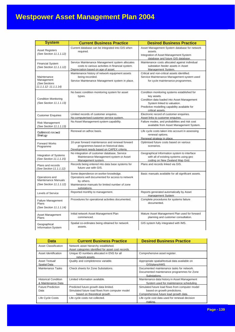
Westpower Asset Management Plan 2004
Page - 139
Data Current Business Practice Desired Business PracticeAsset Classification Network asset hierarchy established.
Asset categories identified for asset cost records.Asset Identification Unique ID numbers allocated in ENS for all
network assets.Comprehensive asset register.
Asset Textual/Spatial Data
Quality and completeness variable. Appropriate spatial/textual data available onGIS/plans/AMS.
Maintenance Tasks Check sheets for Zone Substations. Documented maintenance tasks for network.Documented maintenance programmes for Zone
Substations.Historical Condition& Maintenance Data
Limited information available. Maintenance data history in Asset ManagementSystem used for maintenance scheduling.
Future PredictionData
Predicted future growth data limited.Simulated future load flows from computer model
based on theoretical growth.
Simulated future load flows from computer modelbased on growth predictions.
Comprehensive future load growth data.Life Cycle Costs Life cycle costs not collected. Life cycle cost data used for renewal decision
making.
System Current Business Practice Desired Business Practice
Asset Registers(See Section 11.1.1.12)
Current database can be integrated into GIS whenrequired.
Asset Management System database for networkassets.
Integration of Asset Management Systemdatabase and future GIS database.
Financial System(See Section 11.1.1.12)
Service Maintenance Management system allocatescosts to various activities in financial system.
Depreciation based on age of asset.
Maintenance costs allocated against individualsubstation feeder assets in AssetManagement System.
MaintenanceManagement(See Sections
11.1.1.12: 11.1.1.14)
Maintenance history of network equipment assetsbeing recorded.
Service Maintenance Management system in place.
Critical and non-critical assets identified.Service Maintenance Management system used
for cycle maintenance programmes.
Condition Monitoring
(See Section 11.1.1.13)
No basic condition monitoring system for assettypes.
Condition monitoring systems established forkey assets.
Condition data loaded into Asset ManagementSystem linked to valuation.
Predictive modelling capability available forcritical assets.
Customer Enquiries Limited records of customer enquires.No computerised customer service system.
Electronic record of customer enquiries.Asset links to customer enquires.
Risk Management(See Section 11.1.1.13)
No Asset Management system capability. Failure modes, and probabilities and risk costavailable from Asset Management System.
Renewal on adhoc basis. Life cycle costs taken into account in assessingrenewal options.
Renewal strategy in place.
Forward WorksProgramme
10-year forward maintenance and renewal forwardprogrammes based on historical data.
Development needs based on CAPEX criteria.
Optimised future costs based on variousscenarios.
Integration of Systems(See Section 11.1.1.15)
No integration of customer database, ServiceMaintenance Management system or AssetManagement system.
Geographical Information system to interfacewith all of existing systems using geocoding on New Zealand Map Grid.
Plans and records(See Section 11.1.1.12)
Records being entered into data base systems forfuture use with GIS.
Plans and records linked via GIS.
Operations andMaintenance Manuals
(See Section 11.1.1.12)
Some dependence on worker knowledge.Operations well documented for access to network
by others.Maintenance manuals for limited number of zone
substations.
Basic manuals available for all significant assets.
Levels of Service Reported monthly to management. Reports generated automatically by Assetmanagement System
Failure ManagementPlans(See Section 11.1.1.14)
Procedures for operational activities documented. Complete procedures for systems failuredocumented.
Asset ManagementPlans
Initial network Asset Management Plancommenced.
Mature Asset Management Plan used for forwardplanning and customer consultation.
GeographicalInformation System
Spatial co-ordinates being obtained for networkassets.
GIS system fully integrated with IMS.

Westpower Asset Management Plan 2004
Page - 140
Information Systems are the information support systems used to store and manipulate the data.
Data is that required for effective decision making (ie for manipulation using information systems).
The previous tables broadly describe the current Westpower Asset Management practices and possiblefuture (desired) business practices it is intended to ultimately develop. The Asset Management Improvementplan discusses improvement priorities, timetables and resources for the next 3 years.
The following are specific issues and Asset Management procedures that are currently being addressed.
8.2 Rationalisation of Responsibilities and Procedures
The structure of Westpower’s asset management group continues to develop to meet business needs andlegislative change. Responsibilities, reporting lines, work flows and procedures have been implemented forthe different activities carried out in the office. These activities included action, planning, monitoring andreporting and form the basis of the monthly reporting to management.
8.3 Network Services Operational Support
Westpower uses ElectroNet Services as its preferred maintenance contractor for all network associatedinspection service and testing, faults, fault repair, maintenance replacement and network enhancement.Some development work is put out to tender or, where a third party is involved, outside contractors may carryout this work.
Service level agreements are currently in place with ElectroNet Services for Asset Management and AssetMaintenance. Any larger Enhancement and Development projects will have contracts on a specific projectbasis.
8.4 Information Systems Development
The Asset Management Group has implemented the Service Maintenance Management (SMM) system, thatis used for issuing works orders and reconcile monthly invoices with the purchasing system. Expenditurecan be tracked by activity and by asset type.
Also improvements have been made to the Electrical Network System which keeps information on types ofequipment installed at a site. This information tracks maintenance history of transformers and other associ-ated equipment.
8.5 Specifications, Procedures and Manuals
Westpower has spent considerable effort in preparing a set of manuals for use by contractors, which pro-vides information to contractors on Westpower Specifications, levels of competency, Network Releases andaccess to sites. A set of network design standards are also available to contractors who wish to undertakenetwork extensions and network reconstruction.
Procedures have also been completed which are deemed to be mandatory for contractors who wish to carryout work for Westpower or on Westpower’s network.
8.6 Deregulation/Compliance with MED & Commerce Commision Requirements
The specific external environment in which Westpower operates is the power supply industry in general.
8.7 Electricity Industry Reform Act

Westpower Asset Management Plan 2004
Page - 141
The passing of the Electricity Industry Reform Act (through Parliament on 3 July 1998) signalled a majorchange in the industry.
This has had a far reaching impact on the electricity industry in New Zealand and completely changed theway in which electricity was delivered to the end customer
The Act provided for:-
• Break-up of ECNZ into three competing SOE’s
• Ownership separation of all Line and Energy companies
• Introduction of low-cost retail competition
• Greater performance disclosure by line businesses
• Empowerment of Commerce Commission to impose price control on line charges.
8.7.1 Economies of Scale
A time of relative stability appears to have been reached within the industry with a commensurate reductionin merger and acquisition activity. While there is no direct imperative for mergers and acquisitions intrinsic inthe current legislation, market forces are likely to continue to act on inefficient operators with high fixed costsrelative to their asset base. This is particularly pertinent following the introduction of the new targeted thresh-old regime.
If Westpower is to remain profitable it needs to compare favourably with other lines businesses. Thus thechallenge for Westpower is to remain viable through appropriate cost control and superior standards of assetmanagement. Cost reduction alone is insufficient as it ignores the impact on asset performance, which is avital factor in the continued operation of the company.
A spin-off benefit from an intensified maintenance programme is a major reduction in fault outages, thebenefits of which will be ongoing. When combined with a reduction in planned outages through lower plannedmaintenance activity, a significant improvement in reliability can be expected.
8.8 Commerce Commission Requirements
The Commerce Commission will control information disclosure through the Electricity (Information Disclo-sure) Regulations.
These regulations have a direct impact on Westpower by forcing the line companies to disclose their financialand asset performance data to allow comparison with other line companies. The Commerce Commissionwill be taking a more active roll in these comparisons which could lead to further external interference inWestpower’s asset management practices.
Key performance statistics will need to be disclosed regularly under the proposed legislation, with the firstmajor review for price control purposes being undertaken after two years based on average weighted perfor-mance.
Westpower’s asset management performance will be visible for all interested parties to see and provide astrong incentive to Westpower to maintain and improve current standards. Regular reviews of Westpower’sprocedures will take place based on this disclosed information

Westpower Asset Management Plan 2004
Page - 142
8.9 Regulatory Risk
8.9.1 Pricing Regulation
In December 2002 the Commerce Commission released its Draft Decision on the new regulatory environ-ment for electricity lines businesses. This consists of a targeted control regime whereby individual linesbusinesses will be investigated with a view to imposing individual price control in the event that they exceedparticular thresholds with respect to
1. Price Path2. Reliability3. Profitability.
At present, the proposed price path involves an annual adjustment of Consumer Price Index (CPI) –X% perannum, effectively resulting in a 1% revenue drop in real terms over each year of a five year period beginningin 2003.
If this price path is adopted in the final decision, the resulting reduction in revenue will require that Westpowercontinue to focus clearly on cost reduction, while at the same time ensuring that reliability continues toimprove. The professional asset management planning processes applied by Westpower over the last tenyears have placed to company in an excellent position to respond to the challenges of the new environmentwith a well-maintained asset base. New disciplines required by the regulatory environment will be incorpo-rated into future asset management plans.
Westpower’s asset management will be targeted at providing the maximum service quality possible at thelowest price and cost while, at the same time, staying within regulatory limits.
Countervailing Power
Further pressure will be brought to bear by the monopsony power of vertically integrated generation/energycompanies (gentailers). This countervailing influence will reduce Westpower’s ability to set tariffs with strongprofit margins as the supplier and retailer will effectively be acting in unison during negotiations.
To use an illustration put forward by some commentators, the lines businesses will effectively become “truck-ing companies” used to shift electricity from generators and Transpower grid connection points to customers.The only difference is that Westpower owns all of the “trucks” in the area.
What the overall effect of these changes will be is difficult to forecast. It can be said with some certaintyhowever that the lines businesses will be operating in a highly regulated market including both price andprofit control with little opportunity for growth apart from that caused by a general upturn in the economy.Increasingly dominant and demanding suppliers and customers will exacerbate this situation.
The direct effect of this will be the need for Westpower to operate in an efficient manner to reduce costs
8.10 Asset Renewal Policy
The General renewal strategy is to rehabilitate or replace assets when justified by:
• Asset performance
Renewal of an asset is where it fails to meet the required level of service. The monitoring of asset reliability,capacity and efficiency during planned maintenance inspections and operational activity identifies non-per-forming assets. Indicators of non-performing assets include:

Westpower Asset Management Plan 2004
Page - 143
Renewal Criteria
1 (High) Asset failure has occurred.Asset failure of critical system component is imminent.Regular maintenance required.Complaints
2 Failure of non-critical asset is imminent and renewal is the most efficient life cycle costalternative.
Maintenance requiring more than six visits per year.
3 Reticulation maintenance involving two to three visits annually.Difficult to repair, due to fragile nature of material, obsolescence.
4 Existing assets have low level of flexibility and efficiency compared with replacementalternative.
5 (Low) Existing asset materials or types are such that known problems will develop in time
Priority
• Structural life• Repeated failure• Ineffective and/or uneconomic operation• Economics
Renewals are programmed with the objective of achieving:
• The lowest life cycle cost for the asset (uneconomic to continue repairing), or
• An affordable medium term cash flow, or• Savings by co-ordinating renewal works with other planned works• Risk
The Risk of failure and associated environmental, public health, financial or social impact justifies proactiveaction (e.g. impact and extent of supply discontinuation, probable extent of property damage, health risk etc).
Planned and reactive replacement works can be prioritised in accordance with the priority ranking shown inthe following table.
8.11 CAPEX Analysis
Capital expenditure needs to be carefully targeted to ensure that the greatest benefit is reaped from eachcapital dollar expended.
Westpower has always had a policy of producing well-researched business cases for major capital projects.A Discounted Cash Flow (DCF) is used to derive the Internal Rate of Return (IRR) of a project and then tocompare this with the hurdle rate. In general this hurdle rate is equivalent to the Weighted Average Cost ofCapital (WACC) for the business.
Any project that demonstrates a higher rate of return than the hurdle rate will add value to Westpower’sbusiness. If several projects are competing for capital funding, these may be ranked in terms of their rate ofreturn; however caution is needed if the projects are of markedly different size.

Westpower Asset Management Plan 2004
Page - 144
9.0 NETWORK RELIABILITY
This section reviews the current security levels of the Westpower Distribution Network.
In general, Westpower security levels meet accepted guidelines for loads of this size and type.
For loads of 10 MW and above, an n-1 security level are maintained, whereby supply can be maintained forany single component failure. For small loads of less than 1 MW, no backup is specifically provided exceptwhere these are conveniently available e.g. tying 11 kV feeders together.
Supply to the Central Business Districts of Reefton and Greymouth is secure with adequate redundancy builtin. Some work is being done on options to enhance the security of supply to Hokitika where system redun-dancy is limited by a voltage constraint.
Westpower does not use Extra High Voltage cables of the type made famous by the Mercury CBD disasterand is therefore not exposed to a similar risk.
The major risk to the security of supply to the West Coast lies with the Transpower network. There are twolong, exposed feeds into the West Coast, from Inangahua and Coleridge, and at peak times both of these
8.11 Distributed GenerationDistributed Generation is electricity generation equipment connected to the Customer’s installation, andcapable of generating electricity back to the electricity Network, as well as supplying electricity for theCustomer’s own use at the location it is installed.Usually it will be a fixed installation but it may be disconnectable and moveable if required. The installation willinclude all necessary protection equipment required for the safe operation of the Distributed Generationsystem.
In the context of Westpower’s guides for connection, Distributed Generation comprises:
• Small systems of less than 5 kW capacity• Medium systems of between 5 kW and 30 kW capacity• Large systems between 30 kW and 1000 kW capacity.
Small systems are likely to be installed in residential sites and would typically be Solar Panels, but could alsobe other technologies such as Wind powered, Micro-Hydro systems or Fuel Cells.Medium sized systems are more likely to be installed in commercial premises, and utilise existing plant orenergy sources.
Large systems would normally be associated with industrial sites or as dedicated generation facilities.Westpower’s policy is to actively encourage Distributed Generation as a means of reducing system lossesand improving both the reliability and quality of supply to the area.
Customers interested in developing such facilities are invited to contact Westpower’s agent ElectroNetServices to request a copy of the Distributed Generation Information Pack. This pack will provide valuableassistance in planning and engineering an acceptable solution.
Formal application forms will be available to ensure that the appropriate information is provided to allowWestpower to approve connection to its network and ensure compatibility with the existing reticulation net-work.
Any new Distributed Generation installation also requires contractual arrangements to be put in place with aretailer to purchase any excess electricity generated. Westpower may then credit the retailer for the energythat is exported at the same price that the retailer is charged for the delivery of energy, providing a net benefitto the Distributed Generator

Westpower Asset Management Plan 2004
Page - 145
feeds are required along with support from Trustpower generation.
Another area of concern is the exposure of South Westland to the availability of a section of Aerial BundledCable (ABC). Wahapo Power Station provides an effective backup for the section of ABC around LakeWahapo. As the Trustpower Wahapo Power Station is not always available however, this needs to be takenaccount of in assessing overall security to the area.
A recent realignment of the section of ABC around Lake Wahapo has improved the reliability of this link, anda replacement of a similar section around Lake Mapourika with Hendrix Spacer Cable has further reducedWestpower’s exposure.
Local generation has also greatly reduced the risk of major system outages when a Transpower fault occurs.
The security of Westpower’s network is thus considered to be satisfactory given the nature of the terrain andsize of loads involved.
9.1 Westpower Sub-transmission and Distribution Networks
System security and reliability depend on two factors
• Failure Rates
• Repair Times
These two areas will be looked at in terms of the two most common line construction types, cables andoverhead lines, which make up Westpower’s Subtransmission and Distribution Networks
9.1.1 Cables
In general, cables are very reliable as they are not exposed to the external environment and if carefully laid,should give at least 50 years of good service. The most likely mode of failure is damage by contractors usinghydraulic excavators.
Whilst the failure rate of cables is relatively low however, the Mercury CBD experience demonstrated thatrepair times are critical. Underground cables are the major constraint in this area. In fact, in the Mercurycase, when the 110 kV cables failed, it took several weeks to repair and repressurise each cable.
In Westpower’s case, the highest voltage underground cables it operates are at a voltage of 33 kV, and theseare of standard Paper-Lead construction over a very short distance of less than 100m with backup.
The majority of Westpower’s underground HV cable network consists of 11 kV cable of both Paper-Lead andXLPE construction. Both of these are dry-type constructions that allow for joints to be readily made withinfour hours after the fault has been located and the trench dug.
In the Greymouth area, the reticulation in the Central Business District (CBD) consists of a double-redundantring of 11 kV cables. At least two separate HV cables would have to fail to cause an outage of a distributiontransformer. Even if this was to happen, the LV networks are highly interconnected and would continue tosupply most of the load.
All of Westpower’s cables are operating well within their thermal ratings, even taking account of the possibil-ity of poor thermal resistivity backfill.

Westpower Asset Management Plan 2004
Page - 146
9.1.2 Aerial Bundled Cable
There is a section of 33 kV Aerial Bundled Cable (ABC) in South Westland forming part of the 33 kV Sub-Transmission Network.
Until recently, this section of ABC through the bush near Lake Wahapo, exhibited both high failure rates andlong repair times. This section of line has recently been rerouted alongside the State Highway which hasresulted in greatly improved reliability.
The failure rate has reduced because there are no longer large trees falling through the line. Furthermore,because there is good roadside access along the full length of the route, repairs can be effected very quickly.At the same time, a new type of heatshrink repair joint has been introduced for faster repair times.
As an example, the only fault on this line since the shift, occurred on an evening in December 1997. Thisresulted in South Westland being fed from Wahapo Power Station for the night. At first light the next morning,a repair crew was mobilised and a full repair completed within about four hours. Previously, it could take upto two days to effect a repair when all repair equipment had to be carted into the bush.Wahapo Power Station is the backup supply to the area when the Wahapo ABC fails, and providing water isavailable, all of the load in the area will be supplied. If Wahapo is unavailable, there is no alternative feed.
For the section of line around Lake Mapourika there is no alternative feed as this is located South of Wahapo.Part of this cable is also situated away from the road, increasing repair times. An alternative Spacer Cablesystem was constructed in 2000 around the State Highway, which has increased the reliability of this sectionof line.
Alternative risk management scenarios involving standby diesel generator merit further consideration for thistype of fault.
9.1.3 Overhead Lines
Most of Westpower’s reticulation consists of overhead lines.
Over the past fifteen years, all of the major 33 kV and 11 kV feeders have been replaced or refurbished andare in very good condition overall.
While overhead lines are subject to more faults than underground cables, due to such things as lightning andbird strikes, it is relatively easy and quick to get them back into service.
The maximum repair time of about three hours is required when a complex pole structure is damaged due tosay a vehicle running into it.
Distribution automation equipment installed over recent years has allowed Westpower to quickly diagnoseand locate rural faults, and then restore supply remotely to adjacent areas without having to get staff on site.
Spares of all types of conductor and poles are kept in stock to cover most eventualities. Access to othernetwork company’s stocks is likely in the event of a major disaster.
9.2 ZONE SUBSTATIONS
Westpower operates 15 Zone Substations at Reefton, Ngahere, Rapahoe, Dobson, Arnold, Greymouth,Kumara, Hokitika, Ross, Waitaha, Harihari, Whataroa, Wahapo, Franz Josef and Fox Glacier. These sub-stations are used to feed the 11 kV distribution networks and are therefore key components as far as networksecurity is concerned
Dual transformers are installed at Greymouth and Hokitika substations, in comparison to the other substa-tions, which rely on single transformers. The large power transformers installed at these sites are veryreliable however and rarely give problems.

Westpower Asset Management Plan 2004
Page - 147
Westpower’s network has been designed so that in the event of a power transformer failing, the networkcould be reconfigured, and a spare unit sourced from either elsewhere in the network or the emergencyspare stock.
The switchgear and protection equipment is relatively modern and well maintained with many years of effec-tive life still remaining.
The following tables give a breakdown of network reliability by Zone Substation and feeder. This shows thatmany feeders have some form of backup and that appropriate spare transformers are held for all majorsubstations.
9.3 TRANSPOWER NETWORK
The major risk to the security of supplyto the West Coast l ies with theTranspower network.
There are two long, exposed feeds intothe West Coast, from Inangahua andColeridge, as shown on the adjacentmap, and at peak times both of thesefeeds are required along with supportfrom the Trustpower generation. Thesignificant costs involved in providingextra security above the existing levelsmake this prohibitive
(NB. This plan was prepared in June2002 and since that time the ArahuraSubstation has been replaced byHokitika.)
The construction of the twin-circuitKumara-Kawhaka line in May 1997 byWestpower has greatly improved secu-rity of supply to the Kumara andGreymouth supply points.
9.4 Overall Reliability
It is considered that the levels of secu-rity are appropriate for Westpower’s net-work in line with industry best practicefor loads of this size and type

Westpower Asset Management Plan 2004
Page - 148
Reefton 2.5 1 CB1
CB3
CB3 at Sub
CB1 at Sub
NGA CB1 to Maimai
This substation is dependent on the integrity of the radialfeeder from Dobson.Repair times are short. A backup transformer is availableex Dobson.
SubstationLoad(MW)
# HVFeeds
Feeders Backup Comments
Ngahere 2.6 1 CB1
CB3
DOB CB1
ALD CB4
RFT CB1 to Ahaura
There is no backup for a 33 kV feeder fault. Backup isavailable for the Blackball feed from Dobson or Arnold.Partial back feed from Reefton to Ahaura is possible.Repair times are short. A backup transformer is availableex Dobson. In a substation fault, alternate feeds are notlarge enough to supply the major connected load, theNgahere Gold Dredge.
Rapahoe 4.0 1 CB1
CB3
CB3 at Sub
DOB CB1
There is no backup for a 33 kV feeder fault. Backup isavailable via a bypass switch for 33kV and 11 kV circuitbreaker faults. Dobson is able to supply the domestic11 kVload and minimal industrial load e.g. mine pumps. Abackup transformer is available ex Dobson. Repair timesare short.
Dobson11kV
2.7 1 CB1
CB3
RAP CB3
ALD CB3
NGA CB1
GYM CB8
This substation is fed directly from the TranspowerDobson 33 kV bus, and so is not subject to WestpowerSubtransmission Line Faults. The 33/11 kV transformeralso acts as a spare, which can be transported to Ngahere,Rapahoe, Hokitika, Wahapo or Franz Josef if required.Several 11 kV ties exist for the feeders out of thissubstation and repair times are short.
Dobson33kV
6.6 2 CB1322
CB1342
CB1362
CB1382
CB1362 at Sub
No Backup
CB1322 at Sub
11kV Tie to Arnold
This is the major 33 kV supply point for the Grey Valleyand is supplied direct from the Trans Power network. Theradial 33 kV feeders can be bypassed at the substation forcircuit breaker faults but there are no alternate feed for thefeeders themselves. Repair times are short. CB1382 is notprovided with a bypass, as Arnold Power Station providesan alternate source on the 11 kV network
Arnold 1.8 1 CB3
CB4
DOB CB1
KUM CB4
The backup for a 33 kV feeder fault is the local generatingstation tied in through the 11 kV network. Backup isavailable for the Stillwater feed from Dobson, and for theMoana feed from Kumara.Partial back feed to Dobson or Turiwhate is possible.Repair times are short. A backup transformer is availableex Dobson.
Greymouth 11.0 2 CB7
CB7
CB13
CB6
CB12
Cb11
CB12
No backup
CB6
DOB CB3
CB13
CB11
KUM CB1
CB7
CB11
CB6
CB12
This is Westpower’s largest Point of Supply that feeds theGreymouth Central Business District (CBD).There are several radial 11 kV feeders that are intermeshedat several points providing a significant amount ofdiversity.The Cobden Feeder has no backup once it crosses the GreyRiver, however the reticulation is all overhead with lowrepair times.The 11kV cable network in the CBD is highly intermeshedwith a “double-ring” construction. All substations havetwo, and many three, 11 kV cable feeds.
Kumara 1.1 3 CB1
CB4
GYM CB6
ALD CB4
HKK CB10
This supply is fed directly from the Kumara 11 kV bus,which is in turn supplied by a very reliable Transpower 66kV bus. Both 11kV feeders can be back fed fromGreymouth, Arnold or Arahura Substations. A sparetransformer is available from Greymouth Substation.
Hokitika 12.0 2 CB10 CB4
CB9CB5
CB4
CB12
CB5
CB11
CB11
CB10
CB11
CB9
CB4
CB5
CB13
CB9
WAH1512
CB12
This substation feeds Hokitika and all of South Westlanddown to Paringa.
In addition, it supplies 3 feeders to the Westland Dairy.

Westpower Asset Management Plan 2004
Page - 149
Ross 0.8 2 CB1
CB3
No Backup
HKK 10 Partial
CB1 is a dedicated feeder for the Birchfield Minerals minesite. Domestic load on CB3 can be fed from AHA C310 butthis is severely voltage constrained. Both feeders have ashort repair time.
Waitaha 0.1 2 CB1 No Backup The 33 kV substation feed can be from Arahura orWahapo if the Wahapo Power Station is available. This isa very small and isolated substation and no backup ispossible for the 11 kV feeders. A spare transformer isavailable.
Harihari 0.3 2 CB1
CB3
CB3 at Sub
CB1 at Sub
The 33 kV substation feed can be from Arahura orWahapo if the Wahapo Power Station is available. This isa small and isolated substation and no backup is possiblefor the 11 kV feeders apart from a bypass for the 11 kVcircuit breakers. A spare transformer is available.
Whataroa 0.3 2 CB1 No Backup The 33 kV substation feed can be from Arahura orWahapo if the Wahapo Power Station is available. This isa small and isolated substation and no backup is possiblefor the 11 kV. A spare transformer is available.
Wahapo 0.05 1 CB1 No Backup The 11 kV substation bus can be fed from Arahura orWahapo if the Wahapo Power Station is available. This isan isolated substation and no backup is possible for the 11kV. A spare transformer is available from Dobson. Thissubstation also connects Wahapo Power Station intoWestpower’s sub-transmission network.
Franz Josef 2.2 1 CB1 CB3 at Sub
CB1 at Sub
This substation, ffed from Hokitika feeds the Franz Josef area.There are two sections of Aerial Bundled Cable in this feeder, which terrain
have significant repair times. The aerial routes andcan be very difficult. There is no feasible backup.
CB3
Fox Glacier .4 1 CB1 This substation was constructed in 2003 to supplythe Fox Glacier area, south to Paringa.

Westpower Asset Management Plan 2004
Page - 150
10 RISK MANAGEMENT PLAN
Westpower has a separate Risk Management Plan completed as part of its overall business planning strat-egy. This included Business Impact Analysis and Business Continuity Planning.
In addition, Westpower is actively involved in a regional Lifelines project looking at ways of managing therisks involved with major disasters and ensuring that plans are in place to deal with most of the likely sce-narios.
A copy of the full Risk Management Plan is available from Westpower on request, however a general over-view of the process is included below to demonstrate the robust and professional approach taken to thisimportant aspect of planning.
10.1 Risk Management Planning Framework
A detailed risk assessment was conducted which:
• Defined specific risks.• Assessed the potential impact of each risk on a six-point scale from 100 [Minor] to 600
[Critical].• Assigned management responsibility to each risk.• Identified current control measures for all risks with a potential impact of 400 [Major] or
above and rated the effectiveness of the controls.• Explored the likelihood of occurrence.• Documented the results.
The methodology adopted was consistent with the joint Australian and New Zealand Standard AS/NZ4360:1999. It is a simple and effective method but remains subjective. The validity of the risk control assess-ments may require further investigation and analysis by Westpower, particularly where the risk is critical tothe business. An example of the one of the outputs is shown below.
Risk Factor Rating Recommendations
Physical Security 30 Review security requirements for each of the sub-stations.In particular investigate benefits of installing an alarmsystem in Franz Josef sub-station monitored throughSCADA and personal pagers
Key Register needs to be updated and unreturned keysretrieved where possible. If this can not be done then anassessment should be made of critical security points andlocks replaced in these places.
Plant Maintenance 24 Continue the process of improvement of the existing plantmaintenance and life cycle planning and reportingstrategy.
Ensure that the Service Maintenance Module (SMM)enhancements are matched with any revisions to theplant maintenance strategy.
Review the process of issuing scheduled work orders toensure a match to the Asset Management Plan. Need toensure there is a high degree of consistency.

Westpower Asset Management Plan 2004
Page - 151
10.2 Risk Planning Methodology
The risk management team facilitated a workshop with Westpower management to work through and assessthe impact of 60 risks presented in a framework under 13 categories.
The diagram shown below charts the methodology used for Westpower. In the diagram below the processboxes, numbered 1-10, correspond with the process methodology stage descriptions that follow.
POLICIES,PROCEDURES,ACCEPTEDPRACTICE,STANDARDS
ASSESS POTENTIALCONSEQUENCE OF
RISKS
RISKFRAMEWORKIDENTIFY
RESPONSIBILITY
LIST OUT HIGHPOTENTIAL
IMPACT RISKS
PRIORITISE RISKS
MONITOR RISK CONTROLAND IMPROVEMENT
PROGRESS
DECIDE ACTIONSTO IMPROVE
PROFILE
RISK PROFILE
RISK ACTIONPLANS
REPORTING ANDSIGN-OFF
ASSESS CONTROLEFFECTIVENESS
ASSESSLIKELIHOOD OFOCCURRENCE
IDENTIFYCURRENT
CONTROLS
REVIEW CONTROLWEAKNESSES AND
LOSS HISTORY
CALCULATEEXPOSURE ANDRESIDUAL RISK
RISKTEMPLATES
BUSINESS RISKS
LEGISLATIVECOMPLANCE RISKS
RESPONSIBLESTAFF
INPUTS TOOLSPROCESS
1
2
4
3
5
6
7
8
9
Outstanding Actions
10

Westpower Asset Management Plan 2004
Page - 152
Stage 1. Assess Potential Risk ConsequenceRisk is measured in terms of consequence and likelihood. At the workshop, Westpower management as-sessed the potential impact of each risk on the organisation. Their assessment of the potential risk conse-quence was based on the following table developed in consultation with senior Westpower Management.
RISK CONSEQUENCE TABLE - Westpower Limited
Rating Level Possible Impact on CompanyAnnualisedFinancialImpact
600 Critical Board approval for actions and on-going support from theCompany's bankers required.
High Priority actions needed to recover situation
Loss of stakeholder support
Major stakeholder concern
Viability of Company threatened
Greater than $5million
500 Severe Direct Intervention of the Board. Urgent and sustained Management action required toprevent crisis.
Stakeholder unease and reduced support
High number of people affected by an incident or over year by incidents
Between $1million and $5million
400 Major Immediate Management action needed to control thesituation.
Multiple incidents affect a significant number of people a yearin total (Non-random)
Major stakeholder concern
Adverse national media coverage (TV, radio and print)
Between$500,000 and$1 million
300 Significant Management action needed to prevent escalation. Multiple incidents affect a significant number of people a yearin total (Random)
Widespread complaints (public and community organisations) Adverse national media coverage (print)
Between$100,000 and$500,000
200 Moderate Action needed to confirm controls
Adverse local media coverage (not picked up nationally)Localised complaints (small groups or communities)
Single incident affects a small number of people
Between$50,000 and$100,000
100 Insignificant Covered under normal Management actions Negative local media coverage
Personal grievance claim
Less than$50,000
Stage 2. Identify Responsibility
One of the tasks completed at the workshop was to identify the responsible person for each of the risks givena consequence rating. It is the person identified that is best able to rate the current control methods andweaknesses.

Westpower Asset Management Plan 2004
Page - 153
CONTROL EFFECTIVENESS TABLE - Westpower Limited
ControlEffectiveness
Descriptor Definition
95% ExcellentThe controls in place mitigate the risk to the maximum extentand are being performed in the manner for which they weredesigned
80% Very good The controls and procedures are very good. There is smallroom for improvement.
70% GoodThe majority of the risk is managed, however there ispotential for the controls to fail. An improvement isrecommended.
55% AdequateThe controls and procedures manage the risk at face value.There is a great reliance on them operating correctly withoutany checks or assurances.
45% + Unacceptable The controls manage only some of the risk.
30% + Non-existent The controls are largely passive.
Stage 3. Identify High Consequence Risks
A key aim of the risk workshop was to separate out the significant, high-impact risks for further attention fromthose with lesser impacts. Using a cut-off risk impact level of 400 we prepared the following list of risks topursue further. Each of these risks were assessed in detail in interviews conducted with the staff responsibleidentified at the workshop.
Risk Consequence
Financial Management 400
Illegal or Unacceptable Behaviour 300
Government Regulation 550
Inventory Management and Purchasing 300
Project Management 500
Staff Planning 400
Succession Planning 400
Revenue Protection 400
Business Continuity Planning 500
Stage 4. Identify Current Controls
As part of the interview process, each high impact risk was discussed in detail and a description of thecurrent control methods obtained. These results were captured in Risk Templates .
Stage 5. Assess Control Effectiveness
Next, the control effectiveness of the current control methods was assessed using the following rating scale.
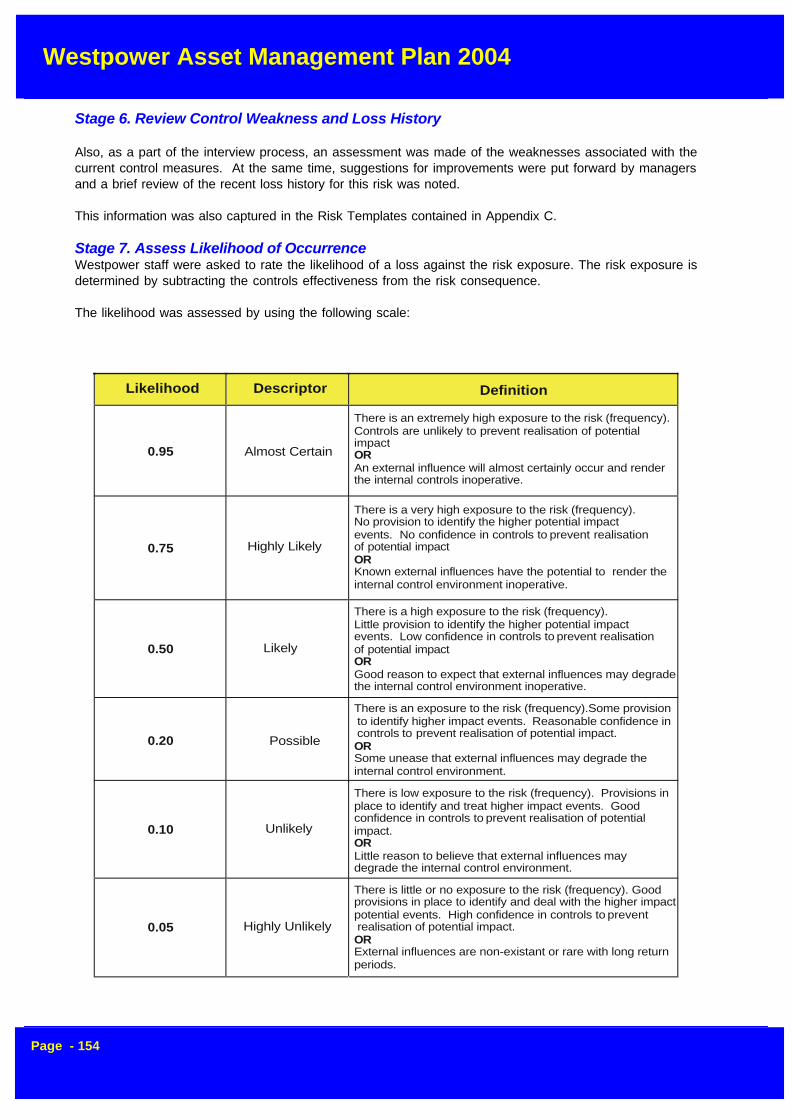
Westpower Asset Management Plan 2004
Page - 154
Stage 6. Review Control Weakness and Loss History
Also, as a part of the interview process, an assessment was made of the weaknesses associated with thecurrent control measures. At the same time, suggestions for improvements were put forward by managersand a brief review of the recent loss history for this risk was noted.
This information was also captured in the Risk Templates contained in Appendix C.
Stage 7. Assess Likelihood of OccurrenceWestpower staff were asked to rate the likelihood of a loss against the risk exposure. The risk exposure isdetermined by subtracting the controls effectiveness from the risk consequence.
The likelihood was assessed by using the following scale:
Likelihood Descriptor Definition
0.95 Almost Certain
There is an extremely high exposure to the risk (frequency).Controls are unlikely to prevent realisation of potentialimpact
An external influence will almost certainly occur and renderthe internal controls inoperative.
OR
0.75 Highly Likely
There is a very high exposure to the risk (frequency). No provision to identify the higher potential impactevents. No confidence in controls to
prevent realisation of potential impact
Known external influences have the potential to render theinternal control environment inoperative.
OR
There is a high exposure to the risk (frequency). Little provision to identify the higher potential impactevents. Low confidence in controls to
prevent realisation of potential impact
Good reason to expect that external influences may degradethe internal control environment inoperative.
OR
There is an exposure to the risk (frequency).Some provision to identify higher impact events. Reasonable confidence in controls to prevent realisation of potential impact.
Some unease that external influences may degrade theinternal control environment.
OR
There is low exposure to the risk (frequency). Provisions inplace to identify and treat higher impact events. Goodconfidence in controls to prevent realisation of potential impact.
Little reason to believe that external influences may degrade the internal control environment.
OR
There is little or no exposure to the risk (frequency). Good provisions in place to identify and deal with the higher impactpotential events. High confidence in controls to prevent realisation of potential impact.
External influences are non-existant or rare with long returnperiods.
OR
0.50 Likely
0.20 Possible
0.10 Unlikely
0.05 Highly Unlikely

Westpower Asset Management Plan 2004
Page - 155
ANNUALISEDPOTENTIAL RISKCONSEQUENCE
CONTROLEFFECTIVENESS
RISKEXPOSURE
RISKLIKELIHOOD
RESIDUALRISK LEVEL=X_ =
Risk Residual Rank
Government Regulation 114 1
Legislative Compliance 90 2
Business Continuity Planning 55 3
Capacity 50 4
Strategic Planning 45 5
Fire Protection 45 6
Stage 8. Calculate Exposure and Residual RiskAppendix C shows the results of the interviews as a series of templates that captures the key informationabout each risk. These templates include descriptions of the control methods and weaknesses as well as thecalculation the residual risk value using the following formula:
Stage 9. Prioritise RisksBy using the risk assessment formula shown on the previous page, we were able to prioritise the top risks forWestpower based upon the residual risk level. The risks are shown in order in the following table:
Stage 10. Action Plan Development
The Risk Management Team believes that any risk with a residual rating of 40 or above should be matchedby a corresponding Action Plan. There were 6 risks above this figure.
The suggested action plans developed by Aon have been included in Section 4 of this Report. These wereformulated from discussions held with key staff during the interview phase. These will be further developedby Westpower leader in consultation with the Risk Co-ordinator and Aon.
10.3 Failure Mode and Effects Critically Analysis
Asset failure will be managed using the failure mode and effects critically analysis (FMECA) process. Thisforms part of the "desired practice" for optimised renewal strategy as outlined in Table 6.1.
Having identified the failure modes, risk costs and treatment options for key assets, the appropriate optionwill be included in the Asset Management Plan. This process and typical failure modes, effects and treat-ments are summarised in figures 10.3a and 10.3b.

Westpower Asset Management Plan 2004
Page - 156
IDENTIFY FAILURE MODES
AVAILABILITYCAPACITY
RELIABILITYLEVEL OF SERVICE
MORTALITY COST
ASSESS CONSEQUENCE OF FAILURE COSTSDIRECT & INDIRECT BUSINESS RISK COSTS TO BUSINESS
DETERMINE TREATMENT OPTIONS AVAILABLE TO REDUCECONSEQUENCES OF FAILURE
IDENTIFY MOST APPROPRIATE TREATMENTOPTION FOR BUSINESS
IDENTIFY FAILURE MODES
AVAILABILITYDEMAND
CAPACITYQUALITY
RELIABILITYPERFORMANCE
LEVEL OF SERVICE
MORTALITYEND OF
PHYSICAL LIFE
COSTPERFORMS OKAYBUT COSTS TOO
MUCH
DemandExceedsCapacityQuantity
DemandInadequate
Utilisation ofAssets is Poor
Asset is Unreliableand InterruptsService Delivery toUnacceptableLevels
Non-performingFinancially TechnicallyInefficient or Obsoletehas Poor Utilisation andDerives Low Income
Asset StillPerformingAdequately ButFailure Likely
Fails to MeetLevel ofService orStandardsRequired
High Cost ofService Non-Performing Asset(Financially)
High Number ofFailures Impacts onCustomers PoorLevel of Service
Loss of ServiceImpactDependent onDirect / IndirectConsequences ofFailure
High Maintenance and /or Operating Costs
High DepreciationFailure Liabilities etc
AssetAugmentationNew AssetDemandManagement
AssetDisposalRationalisationIncrease IncomeContinue Subsidy
ImprovementMaintenance
RedesignRehabilitateReplace / DisposeLower Service
Level
Complete RiskAssessment
IdentifyOptimisedRenewal
RationalisationDisposalOptimised RenewalLower Levels of
Service ResponseTimes etc.
Figure 10.3a - Failure Modes Analysis Process
Figure 10.3b - Typical Failure Modes, Effects and Treatments

Westpower Asset Management Plan 2004
Page - 157
10.4 Safety
Safety is always a prime driver in and risk management strategy and Westpower takes this seriously. Toensure that these matters are properly addressed, a formal Health and Safety Committee structure has beencreated and this committee comprises a wide range of staff from all areas of the business.
In addition, Westpower’s contractor, ElectroNet Services Limited, has been audited by the AccidentComplensation Commission (ACC) and received a tertiary level grading for its safety processes and systems,the highest grading available.
Safety is kept to the fore through regular refresher courses and staff training programs designed to enhancethe awareness of safety issues throughout all aspects of the workplace.
In addition to the above, Westpower ensures that an active Hazard Identification Program is in place includingthe development of registers for specific types of hazard. At Zone Substations, hazard identification noticeboards are used to inform all personnel coming on to site of what the currently identified hazards are and theyare encouraged to add to the list any new hazards that present themselves.
New equipment is always checked for safety and specific operational procedures developed where necessary.All manufacturers are required to supply Material Safety Data Sheets for substances used in the workplaceand this is kept in a readily available register.
10.5 Environmental
Oil spills are the most likely form of environmental damage that is likely to occur as a result of Westpower’sactivities. This risk has been specifically identified for further attention and has been reported at Board level.
To mitigate this risk, Westpower has had in place an active program to upgrade bunding at all major substationswhere there are oil containment vessels with a capacity of more than 1500 litres. The one remaining ZoneSubstation sites that fit this criterion will be upgraded early 2004.
Spill response kits are supplied to all major sites and staff are trained in their use to mitigate the impact of anypotential spill.
10.6 Key Risks Identified
Key risks for Westpower are similar for most lines businesses and are mainly due to climatic and seismicfactors.
Westpower has identified the following major risks to its ability to supply electricity
• Earthquake• Storms (including high winds)• Lightning• Flooding• Ripple injection system failure
Earthquake
The likelihood of a major earthquake on the West Coast due to slippage on the Alpine Fault is considered tobe relatively high within the next 50 years. There is very little that can be done to minimise the risk to overheadlines and cables in the event of an earthquake, but it is also relatively straightforward to straighten poles andrestring conductors as long as access and materials are available.A seismic withstand report was prepared for most Zone Substations in the 2003/04 year to identify anyseismic strengthening measures that can be taken to mitigate the impact of a major earthquake.
Westpower Asset Management Plan 2004
Page - 158
In addition, Westpower closely co-operates with other lines businesses and uses similar industry standardequipment to ensure that a ready supply of spares will be available if required.
Storm Damage
Westpower faces this risk regularly with several major storm events experienced in any one year.
Damage is caused by poles being blown over or trees or other large objects being blown into the overheadlines.
Westpower mitigates this risk by maintaining a regular pole inspection program to check that poles areadequately rated for the service they are likely to face. Any poles that are found to be substandard arereplaced quickly.
A wide range of spares are kept by Westpower’s contractor, including poles, conductor, fittings and transformersto ensure that storm damage can be readily dealt with. The level of spares holding for various types ofequipment have been developed through experience over a number of years and a regular reporting andreordering program is maintained to ensure that minimum quantities are maintained.
In addition, regional depots are maintained at Reefton, Hokitika and Harihari so that a rapid response can beprovided throughout Westpower’s area.
Lightning
The West Coast is quite correctly known as the major lightning incidence region of New Zealand, both interms of strike density and intensity.
As Westpower has had to live with this phenomenon over many years, it has developed design practices tominimise the damage caused by lightning strikes. These include the fitting of modern surge diverters on alldistribution substations, something not common in most parts of the country.
For Zone Substations, Station Class (Line Discharge Level 3) Arrestors are fitted on the terminals of all majorpower transformers and overhead shield wires are fitted on incoming overhead circuits.
A substantial spares holding is maintained for transformers as this is a common cause of damage for thisplant and severe lightning events can sometimes last for several days.
Flooding
This risk mainly affects ground mounted assets such as pad mount distribution transformers and ring mainunits.
Where possible, the location of this equipment is chosen so that it is at least 300 mm above maximumrecorded flood levels, although this is not always feasible in areas such as the CBD of Greymouth.
In the event of a major flood, operational plans are in place to make sure that power is isolated from plantprior to flooding reaching levels where it could cause causing an electrical fault and possible hazards toworkers and the public. Of course, this is in addition to the normal protection systems used to isolate equipmentin the event of a fault.
Ripple Injection System Failure
The ripple injection system is an integral part of Westpower’s control system for managing demand on thenetwork and providing tariff switching signals for retailers. A failure of the ripple system could result inunmanageable peaks being applied to the system eventually resulting on brown-outs or, under extremecircumstances, blackouts.

Westpower Asset Management Plan 2004
Page - 159
Over recent years, Westpower has diversified its base of ripple injection plants and now has units installed atHokitika, Greymouth and Reefton. These are synchronized together so that if one unit should fail, coverageis provided from the remaining units.
In addition, each unit can be operated locally in an emergency.
To further improve the redundancy and coverage available, a new 33 kV ripple injection plant is to becommissioned at Dobson in 2004/05.
10.7 Mitigation Measures
A number of strategies and plans are in place to mitigate the risks identified to Westpower’s network andoperational capability
1. Regular inspection, service and testing is carried out to check the operational capability of allequipment. This includes checking of vegetation in close proximity to overhead lines and activevegetation management.
2. Distribution automation has been progressively expanded throughout the network over recentyears and this has allowed additional plant to be regularly monitored to give indications of anearly failure.
3. Westpower has Network Design and Construction standards as well as a materials approvalsystem to ensure that only quality materials are used and that a high standard of workmanship ismaintained. This ensures that the integrity of the network protected.
4. Regular staff training is implemented in system operation and the issue of permits so thataccess to the network is always carried out in a safe manner.
5. Contingency Plans and emergency procedures are in place. Included amongst these plans arethe following: -
• Regional Emergency Load Shedding Plan• Electrical Industry Emergency Contact List• Zone Substations - Emergency Operating Order Templates
As discussed above, a number of engineering measures have been taken to mitigate risk including:-
• A healthy complement of spares is maintained so that most eventualities can be covered withoutresort to external support.
• A seismic restraint study is to be carried out remaining Zone Substations during the current financialyear.
• All sites having vessels holding in excess of 1500 litres of oil will be fully bunded by the end of the2004/05 year.
• Development of a fully portable 33/11 kV substation is in the planning stages to provide coverage forsingle transformer Zone Substations. This could also be extended to provide coverage for 66/11 kVsubstation. Sufficient spare power transformers are available to cover faults.
• Spare circuit breakers and controllers have been purchased to cover expected failure rates. • A new 33kV ripple plant will be installed in the 2004/05 year

Westpower Asset Management Plan 2004
Page - 160
11 IMPROVEMENT PLAN
11.1 Asset Management Planning Framework
Westpower's Asset Management status approach is based on evaluating the following key areas of life cycleasset management:
1. Processes and Practices;2. Data and Knowledge;3. Information support Systems;4. Commercial Tactics;5. Organisational / People issues;6. Asset Management Plans.
The relationship between the Asset Management plan and its supporting practices (processes, data andinformation systems) and implementation tactics (commercial tactics and organisational / people issues isillustrated in figure 10.1.
Studies were undertaken using the following inputs:
• Interviews with key Asset Management staff.• Nominal assessments of existing Asset Management practices.• The assessment of key reports.• Audits of selected projects by the Lines Inspector.
• Workshops with Asset management staff.
The following is a detailed description of the key areas evaluated:
AssetManagement
Plan
Information Systems
DataProcesses
Information Systems(Organisational / Commercial)
Westpower Asset Management Plan 2004
Page - 161
11.1.1 Processes
11.1.1.1 Demand Analysis
The provision of infrastructure services really represents the provision of appropriate infrastructure to meetcustomer demands. If an organisation does not understand the demand for asset services from its keycustomers and stakeholders then the assets constructed and maintained may either over provide for thedemand or under provide. It is therefore important that an organisation clearly understands the demand forits services.
In this element Westpower takes into account the following;
• History Records
This assesses the past historical trends in demand and the depth of knowledge the organisation holds.
• Element Break-up
In this instance the knowledge the organisation holds on elements that make up the demand are assessedeg. temperature, unit demand variations, key customer groups, population changes etc.
• Customer and stakeholders Surveys
This sub-element assesses the method by which the organisation has assessed the levels of service andother details required by their customers.
• Trend Predictions
This sub-element assesses the organisation's ability to predict trends in terms of demand and service stan-dards.
11.2 Knowledge of Asset
This element assesses the organisation's processes and practices or policies relating to the methods used toacquire and maintain knowledge of their assets.
The key sub-elements assessed are:
• Hierarchical Level
The depth to which an organisation can access information on assets is vital to the overall AM performance.From a best practice perspective this hierarchical level should be taken down to a maintenance manageditem (MMI) and the information should be capable of been aggregated up to reflect assets, facilities, sub-systems or entire service programs.
• Physical Attributes and Data
This assesses the three priority levels of data namely:
1. Basic (primary) physical attributes;2. Detailed information on the construction of the assets, their manufacture and condition;3. Tertiary level information including risk, maintenance plans, detailed condition assessment and per
formance etc.

Westpower Asset Management Plan 2004
Page - 162
These quality elements vary for individual asset types and Westpower assesses these elements in terms ofthe type of asset being considered.
• Condition
The way in which the organisation assesses the condition of individual assets and their components and theprocess used for recording this data.
• Performance
The way in which the organisation assesses the performance of individual assets and their components andrecords the same.
• Utilisation
This sub-element relates to the knowledge the organisation has on the current demand for the asset serviceand the way in which it is tied to the capacity of the asset.
11.3 Asset Accounting and Costing
This element assesses the quality of the processes used to determine the true cost of service. The audittakes into account the following sub-elements:
• Valuations
The method of valuation used by the organisation, its appropriateness and the accuracy with which thevaluations have been developed. It also assesses the methods used to update this information.
• Depreciation and Effective Lives
The methodology used to establish the effective lives of the individual assets and if necessary their compo-nents and the accuracy of the depreciation calculations.
• Operational Costs
The quality with which the organisation can assess the operations of individual facilities and assets and thebreak-up of these operational costs in terms of labour, energy, chemicals, plant etc.
• Maintenance Costs
The method by which the organisation can assess their maintenance costs (planned and unplanned) includ-ing a break-up of these costs into labour, materials, plant and equipment etc. It also looks at the records ofindirect business costs.
• Renewal Liabilities and Risks
The processes used to identify future CAPEX renewal liabilities including backlog maintenance. This alsoconsiders the way the business reports on its risk exposure.
• Historical Cost Data
The ability of the organisation to identify past historical cost data for individual assets in all areas.

Westpower Asset Management Plan 2004
Page - 163
11.4 Strategic Planning Life Cycle
This quality element assesses the processes used by the organisation to complete their long term strategicplanning and this includes the following sub-elements:
• Failure Mode Prediction
The processes used to predict the way in which individual assets or their components will fail to meet the keyquality elements of service delivery namely:
- Capacity failures;- Reliability or levels of service type failures;- Mortality or physical asset failure;- Cost of service ie. Where the cost of service is likely to exceed the economic return necessary to justify
retention of the asset (or the customer's willingness to pay).
• Risk Assessment
The processes used by the organisation to assess their current risk exposure in regards to asset failure andthe way in which this is assessed as part of their business risk looking at both direct and indirect costs to thebusiness.
• Optimised Decision Making
The decision-making processes used to derive optimised renewal programs. The process reviews assetand non-asset solutions and (from an asset perspective) operations, maintenance and capital expenditurealternatives.
• Life Cycle Costing
The processes used by the organisation to assess the long-term life cycle costs in relation to new invest-ments. It also looks at individual asset strategies and the way in which these are aggregated to developwhole of portfolio type strategies based on least cost to the business in line with customer demands.
• Improvement Programs
The processes used by the organisation to identify cost reduction opportunities or improvements in levels ofservice and the way in which these are used via a continuous improvement process throughout the organisationin both operational and capital expenditure areas.
• Capital Expenditure Valuation
The processes used by the organisation to develop business cases for capital investment and assess thequality of that evaluation process with respect to different sized investments.
• Total Asset Management Plan Production
The ultimate output of a strategic planning process is an asset management plan and this assesses theprocesses by which the organisation put such a plan into production. The quality of the actual plan capableof being produced is assessed as the final element of our asset management assessment process (see Item6).
• Customer Review / Revision
The method by which the organisation presents their long term strategic planning information to their cus-

Westpower Asset Management Plan 2004
Page - 164
tomer and stakeholder groups and the process used to simulate the feedback from customers into their longterm strategic planning.
• Business Goal Linkages
The way in which the business is able to link their overall business goals with actual asset action plans interms of maintenance or capex investment eg. the meeting of environmental objectives and goals with re-spect to the way we plan to operate, maintain and renew our asset systems.
• Budget Rationalisation Process
The process by which an organisation can rationalise their ideal total asset management plan to suit theavailable resources, business drivers or budget constraints. It looks at the way in which this process ensuresthat the organisation gets the best benefit for the dollar that it is expending.
11.5 Asset Creation / Disposal
Once an organisation has identified capital expenditure activities this quality element assesses the way inwhich the organisation creates the necessary assets (or disposes of them should they no longer be re-quired). In this process the following sub-elements are assessed:
• Project Identification
The way in which projects are taken through the budget rationalisation process to actual decisions to createor dispose.
• Project Management
The processes used by the organisation to project manage the various different types of projects that wouldbe involved in the asset creation refurbishment or disposal activity.
• Design / Value Engineering
The processes used by the organisation to optimise the design activity, especially with respect to the way inwhich value engineering is used to optimise the design taking into account the strategic objectives of theasset.
• Construction Standards and Quality Control
The construction standards and processes used in building the assets. It also looks at the way in which theorganisation ensures that they are getting the quality specified or required for the assets concerned and theway in which this construction quality or acquisition quality is assessed.
• Contract Administration
The processes used from a contract administration perspective.
• Asset Hand Over
The way in which the organisation commissions and hands over new or renewed assets and in particular theway in which the necessary knowledge and data is transferred into the operational portfolio and asset man-agement information systems.

Westpower Asset Management Plan 2004
Page - 165
• Asset Rationalisation
The way in which the organisation approaches the issue of rationalising its portfolio and the way in whichassets are identified for disposal.
• Asset Disposal
The way in which the organisation proceeds through the disposal process whether this be actual sale, trans-fer of asset ownership or decommissioning of the asset involved.
11.6 Asset Operations
This quality element looks at the way in which the organisations operate their assets and the key quality sub-elements assessed include:
• Operating Procedures
The quality of the operating procedures used with the individual assets including automated processes andthe type of support systems provided.
• SCADA Systems
The appropriateness of the practices used in system control and data acquisition or automated processesand the appropriateness of the policies set for these investments.
• Operations Manuals
The policies and procedures in relation to operations manuals and the way in which these are availableacross the asset portfolio and staff including the appropriate quality levels from a business risk perspective.
• Emergency Response Plans
The process used to determine the need for an emergency response plan and the policy and guidelinesavailable for the development of these plans. (The plans themselves are dealt with under the data andknowledge section).
• Monitoring and Control
The processes used to monitor and control the systems operations from a performance and cost perspec-tive.
11.7 Asset Maintenance
This quality element looks at the processes and practices used to maintain the individual assets and systemportfolios in line with the business objectives and the overall asset management plan. The sub-elementsassessed in this activity include:
• Policy / Strategy
The overall policy or strategic objectives that the organisation uses for their maintenance functions and theway in which this is linked to their overall asset management plans and business risks.

Westpower Asset Management Plan 2004
Page - 166
• Planning
The way in which maintenance plans are developed and the logic contained in that development followingreliability centred maintenance (RCM) type approaches.
• Scheduling
The methods used to schedule the planned and unplanned maintenance activities and the way in whichthese are prioritised. It also looks at the economic basis behind the processes developed.
• Job Execution and Control Feedback
The processes involved in monitoring and controlling the maintenance works program and the quality of thedata feedback required in both planned and unplanned maintenance activities.
• Maintenance Costing
The method by which maintenance costs, their accuracy and the way in which the indirect costs of unplannedactivity or system shutdowns are recorded. It also looks at the elements of maintenance costs including therecording of non-productive activities such as travel time etc.
• Maintenance Manuals
The quality of the processes used to develop maintenance manuals and their availability to maintenance staffthroughout the organisation.
• Review / Analysis
The review and maintenance analysis process that is used to further refine the maintenance programs in-cluding:
- RCM analysis;- Cost benefit analysis;- Identification of cost reduction opportunities including the assessment of core and non-core activities with
respect to commercial tactics.
11.8 Job / Work Resource Management
This assesses the quality of the processes and practices used to manage the work arising out of thesemiscellaneous operational and maintenance activities. The sub-elements assessed under this categoryinclude:
• Resource Planning
The way in which the organisation is able to predict and plan their future workload and take appropriate actionto level out abnormalities so as to ensure effective workload planning for all personnel.
• Inventory Control
The way in which the organisation is able to link work activities and assets back to inventory systems so thatspare parts, materials etc. can be booked and organised ahead of time to suit the work plan. It also assessesthe quality of the inventory control system in terms of optimising spare parts and materials.

Westpower Asset Management Plan 2004
Page - 167
11.9 Review Audit (Continuous improvement)
This quality element looks at the way in which the organisation has set up its quality systems and processesand the way in which it regularly audits itself and derives specific improvement targets for coming years. Thesub-elements included in this assessment are:
• Improvement Programs Implementation
The process used to monitor and report on the progress being made in all asset management improvementprojects including cost reduction opportunities etc.
• Internal QA Practices
The way in which the organisation completes an internal quality assurance review of its activities and thework that it is completing in the asset management area.
• Cost Reduction Opportunities
The way in which the organisation identifies cost reduction opportunities through the audit process and takesthe necessary action to achieve these outputs.
• Independent Asset Management Audit
The degree to which the organisation exposes itself to independent external audit, the way in which theseaudit projects are developed and the action taken on the auditors reports etc.
• Asset Management Process Diagrams
The available process diagrams and flowcharts that are available to assist staff in this life cycle asset man-agement process.
• Asset Management Quality Manual
The quality of the asset management manuals, policy documents etc. that are available to assist staff in thelife cycle asset management area.
11.10 Data and Knowledge (Data Availability / Quality)
This major quality element looks at the data and knowledge available on the assets and their performance,the forms of that data and its availability or usefulness to the organisation.
The assessment process looks at the following sub-elements:
• Asset Categories
The way in which the asset data has been accumulated and the usefulness of that data from an assetmanagement perspective.
• Hierarchical Level
The level to which data is available and accurate against the various asset components and compares thiswith an appropriate level from a maintenance managed item (MMI) perspective.
• Location

Westpower Asset Management Plan 2004
Page - 168
The ability of the organisation to locate and identify an asset appropriately. Where GIS systems are involvedthen the location is assessed from a spatial electronic perspective.
• Physical Asset Attributes
The quality of the data available in the basic physical parameters or Priority 1 type asset data (Primary data).
• Full Detailed Data
The secondary and tertiary priority data on the assets including manufacturing details or other relevant data.
• Condition Data
The relative condition assessment information that is available at various hierarchical levels of assets andthe way in which this data is graded to provide appropriate intervention and risk reduction strategies.
• Maintenance Data
The actual data available and its quality in terms of maintenance from a history and current cost perspectiveincluding additional data such as:
- Cause of failure;- Activities undertaken to overcome failure;- Impacts or the consequences of failure.
• Job Resource Management
The data available in terms of job management activities including prioritisation and workforce details etc.
• Risk Assessment
The data available from a risk perspective to identify the consequence of failure of the various assets includ-ing:
- Safety;- Environmental damage;- Impact on customers and other associated issues.
It also considers the probability of failure and the ultimate application of risk cost to renewal decision making.Each of these consequences need to be related to the business risks involved.
• Cost Histories
The cost histories that are available against assets in terms of maintenance, operations, renewal and theoriginal creation cost.
• Intervention Options and Costs
The records that are held in terms of costs for standard procedures, activities and rehabilitation techniquesthat allow the analysts to determine the most appropriate long term life cycle cost approach for the assetsconcerned.
• Optimised Renewal Decision Making (ORDM)
Westpower Asset Management Plan 2004
Page - 169
The data available in terms of current strategies for individual asset renewals. With changing technology thisdata will need to be updated at regular intervals and revised or new strategies developed for individualassets. This assessment looks at the ability the organisation has to continually refine and update this data.
11.11 Asset Information (Support) Systems
This primary quality element assesses the asset information systems that are available to the organisation toassist or support the asset management processes.
This assessment looks at the functionality of the various applications required for asset management andassesses this against best practice.
The systems include the following sub-elements namely:
11.12 Primary Applications
• Finance System
The way in which financial costs can be assessed, aggregated and disaggregated in terms of asset manage-ment.
• Customer Records and Complaint System
The ability of the organisation to identify customers served by their assets and to link customer complaintswith either system, facility or individual assets under their control. The assessment takes into account theability of the organisation to monitor the asset performance from a customer perspective.
• Asset Register
The functionality of the asset register and the ability of the register to meet asset management needs in termsof asset hierarchy, aggregation and disaggregation as well as its flexibility in being able to expand andcontract to suit the specific needs of the assets and their management.
• Plans and Records
The system that the organisation has to link plans and records (documents) to individual assets and thelibrary system that is used to relate hard copy plans and/or electronic type diagrams and drawings to indi-vidual assets, facilities or systems.
• Geographic Information Systems (GIS)
The functionality of any GIS system that the organisation may have in place or propose to put in place. Thisis related to the benefits that would be derived from the management of the asset types as owned by theorganisation.
• Maintenance Management System
The functionality and application available through the maintenance management system to enable the properdevelopment of a planned maintenance program, the recording of all unplanned maintenance and the asso-ciated linkages to inventory and job management.
• Operations Manuals and Emergency Response Plans
The quality of the existing operations manuals and emergency response plans and looks at the ways inwhich these systems are linked to assets. It assesses their availability and their accessibility to staff. It also

Westpower Asset Management Plan 2004
Page - 170
reviews the overall quality of the key elements necessary for the appropriate operations plans and emer-gency response plans.
• Job Resource Management System
The ability of the organisation to plan, level and appropriately resource the workloads required through boththeir CAPEX and normal operations and maintenance activities.
• Inventory Spares and Purchasing System
The relative quality and functionality of any inventory system and the way in which it interfaces to the assetmanagement system from point of view of ordering materials and spare parts. It also looks at the way inwhich the system is linked to a purchasing process that will enable the optimisation and purchase of appro-priate materials together with specialist services or contracted activities.
11.13 Secondary Applications
• Condition Assessment and Record System
The condition assessment information system elements and the way in which this data is recorded over timeand enables condition predictions to be made.
• Predictive Models Decay and Cost
The ability of the information systems to predict the future condition, probability of failure and likely futurecosts i.e. maintenance that may be incurred by the organisation.
• Capacity Utilisation Models
The ability of the organisation to properly assess the overall capacity of the asset or its integrated system andto be able to predict future demand capacity failures and their associated risks.
11.14 Life Cycle Applications
Risk Assessment
The information systems available to assist personnel to assess the risks associated with their assets andtheir asset activities. The application is assessed on its ability to complete different levels of risk assessmentnamely; initial, secondary and tertiary and looks at its ability to:
- Develop an economic business risk exposure;- Enable predictive and hindsight calculations;- Develop risks or potential benefits in terms of business goals.
• Treatment or Risk Reduction Cost Options
This application is assessed on its ability to enable staff to extract base estimating data that can be used inrisk reduction opportunities, opportunity assessments (forward cashflows and CAPEX) including:
- Non asset solutions;- Maintenance or operations- Rehabilitation;- Replacement;- Disposal.

Westpower Asset Management Plan 2004
Page - 171
• Optimised Renewal Decision Making
This application is assessed on its ability to assist staff to complete the necessary economic evaluation of thevarious treatment options that may be applicable to the asset renewal, replacement. It also looks at life cyclecosts for the creation of new assets. The application is assessed on its ability to:
- Evaluate a series of alternative options;- Enable the input of data for the various parameters effecting the decision;- Cover the full life cycle of all options;- Enable the easy alteration and completion of various scenarios;- Display the resulting information in a satisfactory manner.
• Project Management Applications
The organisation's applications in regard to project management software and systems and in particular theirability to handle simple or complex projects management tasks.
• Maintenance Analysis Software (RCMIFMECA)
The organisation's applications that assist in maintenance management planning and analysis using reliabil-ity centred maintenance techniques.
11.15 General Overall System Issues
This assesses the integration and user friendliness or effectiveness of the existing applications from a wholeof life asset management perspective including:
• User Friendliness
This sub-element looks at the user friendliness of the various informations system applications from a per-spective of encouraging users to make use of the full functionality thereby deriving a greater effectiveness ofour asset management activities.
• Integration of Systems
This sub-element assesses the level of integration achieved by the various applications especially in theprimary system area and the way in which secondary and tertiary applications are interfaced or integratedwith the primary systems. This assessment concentrates on the effectiveness or efficiency elements of thesoftware and the way in which its integration avoids duplication and the need for multiple entries or dataquality-checking etc.
11.16 Commercial Tactics (Contestability/Contracted Services)
This quality element looks at the commercial tactics employed in the completion of the works identified by thelife cycle processes and practices. It looks at the way in which the organisation ensures the lowest unit costsfor the key activities involved in asset acquisition, creation, operations and maintenance or renewal. Theassessment looks at the way in which the organisation ensures that all elements of business activity areplaced under contestable pressure or are benchmarked to ensure effectiveness and efficiency in thoseareas. The assessment looks at items including:
• Core / Non-Core Activities Identified
The way in which the organisation assesses their core/non core (purchaser/ provider) activities and how thissplit is related to the readiness of the organisation or agency in terms of its information and contracts and theavailability or readiness of contractors to complete the various activities.

Westpower Asset Management Plan 2004
Page - 172
• Packaging of Contracts
The way in which the organisation has packaged up its provider contracts including the overall generaleconomic evaluation as well as the ability of the contracts to maintain true competitive pressure over the longterm.
• Specification Quality
The quality of the contracts or service agreements that will exist for both core and non core activities (man-agement functions).
• Information and Data Available
The quality of the information and knowledge available to the contractors in terms of their asset managementroles and also the quality of the information feedback process required by the contracts.
• Contract Supervision (Performance Monitoring)
The effectiveness and efficiency with which the organisation supervises or administers the contracts in-volved. The assessment looks at the quality assurance processes used and the cost effectiveness of theevaluation system. eg. Detailed random sampling. It also looks at the way in which benchmarking is used tosupplement this process especially in the core purchaser roles.
• Contract Evaluation
The way in which the organisation has gone about assessing its contractor evaluation (in terms of the initialcontract letting) and the way in which their performance is monitored throughout the contract period.
• Support Systems
The way in which the organisation's information systems support the management of these contracts. Itlooks at the way in which the work is identified and issued, the completion of the work and the necessarysupervision or approval roles as well as the ultimate invoicing and payment system.
11.17 Organisational/People Issues
Under this major element Worley-GHD assesses the way in which the organisational structure, roles andresponsibilities support or assist the life cycle asset management functions. The assessment is judgedagainst the key success factors that GHD have witnessed in our work with clients in this area. The key sub-elements investigated include:
• Corporate Sponsorship and Commitment
The organisation's commitment to asset management through their policy and corporate intent type state-ments as well as the direct sponsorship of the program and protection of asset value through the appoint-ment of a single executive manager with that responsibility.
• Asset Management Roles and Responsibilities
The way in which the organisation has allocated responsibility for the various life cycle functions and the wayin which the whole of this process is coordinated across the entire organisation through some form of assetmanagement team and steering committee.
• Asset Management Steering Committee

Westpower Asset Management Plan 2004
Page - 173
The key elements of asset management coordination throughout the organisation including:
- The role of the coordinating group and its responsibilities and direct authorisation;- The make-up of the steering committee- The way in which the steering committee is performing.- Business Asset Management Teams
The way in which individual business units have structured their asset management activity and the way inwhich these individual teams operate from a specific asset or asset service delivery programme perspective.eg. Faults, restoration of electricity supply etc. It also assesses the way in which these teams make use ofthe corporate services available.
• Overall Commitment
The actual overall commitment of the organisation to appropriate best practice in Asset Management. Itlooks at the way in which the overall organisation is working towards its goals in this area.
• Skills and Age Profiles
The organisation's knowledge of its individual staff skills and the general age profile of staff within the AssetManagement area. It assesses how the organisation matches its resource needs to its asset managementplanning capabilities and the way in which succession planning is addressed as a key risk to the business.
• Attitude and Culture
The general demeanour, and attitude of staff throughout the organisation and the way in which they work asa team to ensure the most appropriate outputs in the asset management area. It assesses any work that hasbeen done in this area in terms of monitoring or surveying staff attitudes and the activities undertaken to tryand improve general attitudes throughout the organisation.
• Training Programs
The training structure available to staff in regard to life cycle asset management and the way in which thesetraining programs are integrated into the professional development programs for individual staff members. Italso assesses the way in which the organisation blends both in-house and external training opportunitieswith regard to individual staff.
11.18 Asset Management Plans
This element draws together all of the above quality elements to assess the quality of the organisations AssetManagement Plans (AMP's).
The assessment process looks at the key elements of an asset management plan and assesses theorganisation's current ability in terms of the following components:
• Knowledge of Assets
The organisation's knowledge of its assets and their capabilities to meet the current and projected levels orstandards of service via the AMP is assessed. Key components of asset knowledge include:
- Primary info (location, size, scope)- Physical condition- Levels of service- Performance/reliability- Utilisation and capacity

Westpower Asset Management Plan 2004
Page - 174
• Demand Projections and Forecasts
The organisation's ability to project the forward needs or demands for assets and the levels of service thatwill be required by them.
• Levels of Service
This assesses the organisation's standards and levels of service against the demands by both customersand stakeholders. It looks at the appropriateness of these standards and their relationship to industry prac-tice and business goals. The ability of the AMP to outline methods used to determine the levels of service(i.e. stakeholder consultation) is also assessed. The way in which the organisation has then presented thisinformation to the key stakeholders in the process is also assessed.
• Predicted Failure Modes Prediction and Consequences
The organisation's ability to identify the various failure modes of assets and the accuracy of the timing withwhich these failures are predicted. The organisation's ability to clearly identify the economic consequencesof the predicted failure modes and the business risk exposure they represent in both present and future isassessed.
• Operations and Maintenance
This assesses how the AMP outlines long term operations and maintenance requirements including optimisationof the blend between proactive and reactive maintenance.
• Optimised Renewal Decision Making
This assesses the way in which the organisation identifies the optimal renewal strategy for individual assets,facilities and systems. It includes an assessment in relation to both asset and non asset solutions as well ascapital, maintenance and operating alternative options.
• New Works Identification
The predicted need for new assets or augmentations of the existing systems and assesses the economicevaluation process used to identify both the type of asset required, the time at which it will be required.
• Works Prioritisation
It assesses the way in which the organisation rationalises budgets to suit their current economic viability andbusiness goals. The use of risk cost analysis and cost benefit analysis to rank works is assessed.
• Financial Forecasts (Accuracy and Assumptions)
This assesses the accuracy of, and assumptions, which support the long-term cash-flow forecasts, pro-duced in the AMP. The following components of the cash-flow forecasts are assessed:
- Operations;- Maintenance;- Renewal expenditure- Capital expenditure
• Improvement Planning
This assesses how the AMP outlines a programme for improving the practices which support AM planningand therefore improving the level of confidence in the AM plan.
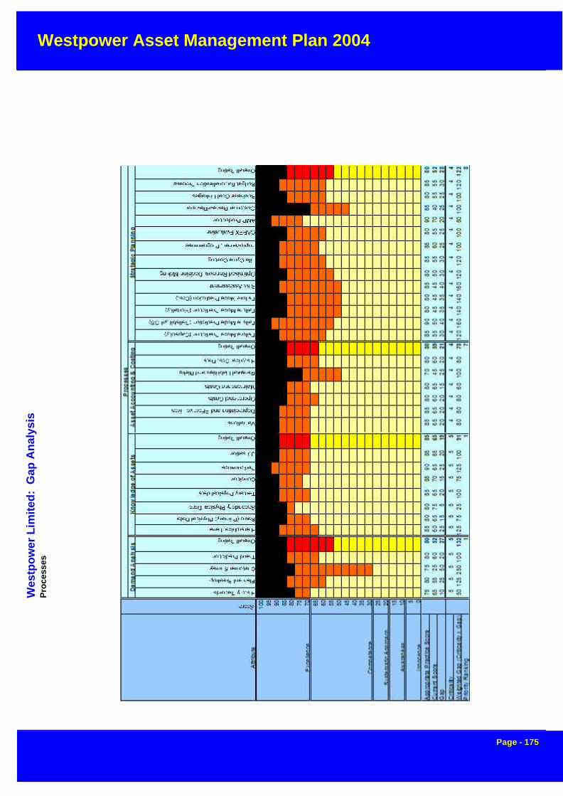
Westpower Asset Management Plan 2004
Page - 175
Wes
tpo
wer
Lim
ited
: G
ap A
nal
ysis
Pro
cess
es

Westpower Asset Management Plan 2004
Page - 176
Westpower Limited: Gap Analysis

Westpower Asset Management Plan 2004
Page - 177
Westpower Limited: Gap Analysis

Westpower Asset Management Plan 2004
Page - 178
Westpower Limited: Gap Analysis

Westpower Asset Management Plan 2004
Page - 179
APPENDIX A
Maintenance Activity Definitions
Inspection, Service and Testing
Routine
This is expenditure on patrols, inspections, servicing and testing of assets on a routine basis. Typically,these activities are conducted at periodic intervals defined for each asset or type of asset. This work doesnot involve any repairs other than some minor component replacements in the course of servicing.
Special Inspection, Service and Testing
Expenditure on patrols, inspections, servicing and testing which are based on a specific need, as opposed tobeing time-based as with periodic inspections and servicing.
Faults
Repairs undertaken during fault conditions to restore supply. This does not include the eventual repair of afaulted asset, where it is taken out of service in the course of repairing the fault; only the expenditure requiredto restore supply is included.
Planned repairs and refurbishment
Repairs to, and refurbishment of an asset, which may involve component replacement but not the completereplacement of the asset. This includes corrective repairs of defects identified within a year, "special" repairs(e.g. based on an identified type failure or type weakness) and planned refurbishment's which may involve asignificant proportion of component replacement. However to identify refurbishment's as distinct from gen-eral repairs would require identification of all specific refurbishment projects over the planning period, andthis has not proved feasible for this plan.
Planned replacement
Replacement of an existing asset with a modern equivalent asset providing similar capacity or other aspectof service provided. Note that the asset need not be identical in capacity etc, but should be materially similar.
Maintenance contingency
An explicit planning contingency, where it is not feasible to identify all minor work, or where it is expected thatwork will arise but its classification cannot be easily predicted. All contingencies are specifically identifiedand no implicit contingencies are included in the detailed expenditure projections for other activity classifica-tions.
This contingency is converted into one of the above activity classifications once committed. Therefore"Maintenance Contingency" is not a real activity for reporting purposes.
Enhancement and Development Activity Definitions
Enhancement
This is the replacement of an existing asset with a modern equivalent asset, which is materially improved onthe original asset, or modifications to an existing asset, which have this effect. Specifically, this will includeimprovements to the existing asset configuration, which are undertaken with the purpose of:

Westpower Asset Management Plan 2004
Page - 180
Further improving the inherent safety of the system (e.g. installing smoke/heat detectors and entry alarms insubstations)
Improving the level of customer service (e.g. increasing capacity by replacing a transformer with a larger unit,or adding an extra circuit to it to increase security)
Improving economic efficiency or investing to improve the asset by reducing operating or maintenance costs(e.g. fitting vibration dampers to specific lines to reduce the rate of component deterioration)
Improving environmental risk management (e.g. fitting oil containment facilities at substations)
Improvement to corporate profile (e.g. landscaping station grounds, although this is also fully justifiable onthe basis of reduced grounds maintenance)
Note that each aspect of improvement is related to a specific Asset Management performance driver.
Development
This is work, which involves installation of new assets in sites or configurations where none previouslyexisted. This may also include substantial upgrade work (e.g. re-building a substation at a higher voltage) inwhich the original configuration is significantly altered or extended.
Development contingency
An explicit planning contingency, where it is not feasible to identify all minor work, or where it is expected thatwork will arise but its classification can not be easily predicted. No implicit contingencies are included in thedetailed enhancement and development expenditure projections. For the same reasons as those discussedunder "Maintenance Contingency", this activity is not included in financial reports.
Other Activity Definitions
Revenue Protection
This is a programme of inspection of all customer meter systems to ensure accuracy and integrity. This is anenergy-related function, but is included in the plan because of future uncertainty over meter ownership.
Operating
Any disconnection of customer's services for any reason except non-payment of electricity accounts. Thisincludes activities such as house painting, transportation of high loads and low voltage switching. It alsoincludes operation of high voltage network where this is not directly associated with maintenance or en-hancement work.
Trees
This activity covers all tree cutting and trimming to maintain safe working clearances from power lines andany costs incurred during negotiations with customers regarding tree trimming.
Asset Type Definitions
High Voltage Lines
Includes all power distribution and sub-transmission lines with a rated voltage of 11kV or higher, together withassociated easements. Within the plan, line work is further desegregated into major line components, being:

Westpower Asset Management Plan 2004
Page - 181
• poles• conductors and accessories
• insulators and hardware
Low Voltage Lines
Includes all low voltage lines with a rated voltage of 400V or lower, together with associated easements, upto the customer's service fuse. As for high voltage lines, line work is further desegregated into major linecomponents, being:
• poles• conductors and accessories• insulators and hardware
Service Lines
Includes all service lines on road reserve from the customer's service fuse to the point at which it crosses thecustomer's boundary. This includes:
• fuse arms
• service fuses• service lines on road reserve
Zone Substations
This includes substation sites and the power transformers within them with a secondary voltage of 11kV orhigher. Individual items of equipment such as disconnectors, circuit breakers and bus-work are covered inother asset type definitions, which are generic for the whole network. That is, no distinction is made betweena disconnector in a substation and one on a distribution line.
• power transformers• other station equipment• regulator sites
Distribution Substations
All distribution substation equipment including
• distribution transformers• DDO fuses• lightning arrestors• earthing systems
Switchgear
All high voltage switchgear and other items of equipment, both on lines and within substations, including
• circuit breakers
• structures and bus-work• instrument transformers• capacitors• protection systems

Westpower Asset Management Plan 2004
Page - 182
• metering• buildings, grounds, fences and other services
SCADA, Communications and Protection
Includes SCADA Master Station and Remote Terminal Units at individual sites. Communication equipmentcomprises specific communications sites and associated equipment and facilities and radio communicationsequipment installed in vehicles and at substations and other bases. Protection assets included in this defini-tion covers protection relays and equipment, which is generally installed at substation site.
Buildings and Structures
Includes all building assets as well as some of the older "bunker" type distribution substations.
Ripple Control
Ripple Injection Plants installed in Zone Substations. This definition also includes the load control softwareincluded in the SCADA Master Station.