Embed Size (px)
Citation preview
Westford Antenna MIT Haystack Observatory
Westford Antenna
Michael Poirier
Abstract
Technical information is provided about the antenna and VLBI equipment at the Westford site of Haystack Observatory, and about changes to the systems since the 2002 IVS Annual Report.
1. Westford Antenna at Haystack Observatory
Since 1981 the Westford antenna has been one of the primary geodetic VLBI sites in the world. Located -70 km northwest of Boston, Massachusetts, the antenna is part of the MIT Haystack Observatory complex.
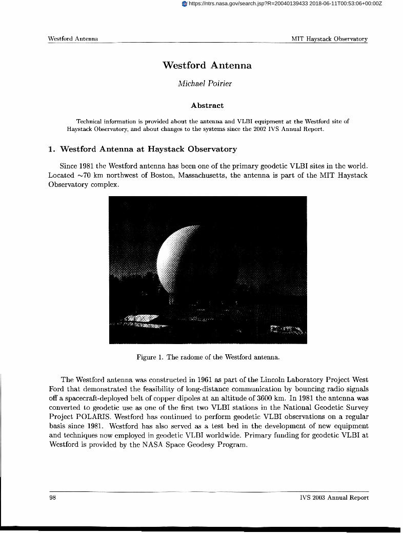
Figure 1. The radome of the Westford antenna.
The Westford antenna was constructed in 1961 as part of the Lincoln Laboratory Project West Ford that demonstrated the feasibility of long-distance communication by bouncing radio signals off a spacecraft-deployed belt of copper dipoles at an altitude of 3600 km. In 1981 the antenna was converted to geodetic use as one of the first two VLBI stations in the National Geodetic Survey Project POLARIS. Westford has continued to perform geodetic VLBI observations on a regular basis since 1981. Westford has also served as a test bed in the development of new equipment and techniques now employed in geodetic VLBI worldwide. Primary funding for geodetic VLBI at Westford is provided by the NASA Space Geodesy Program.
98 IVS 2003 Annual Report
https://ntrs.nasa.gov/search.jsp?R=20040139433 2018-06-11T00:53:06+00:00Z
MIT Haystack Obsenatory Westford Antenna
Table 1. Location and addresses of Westford antenna.
71-49" W
Off Route 40 Westford, MA 01886-1299 U.S.A.
I http://urrv.haystack.mit.edu I
2. Technical Parameters of the Westford Antenna and Equipment
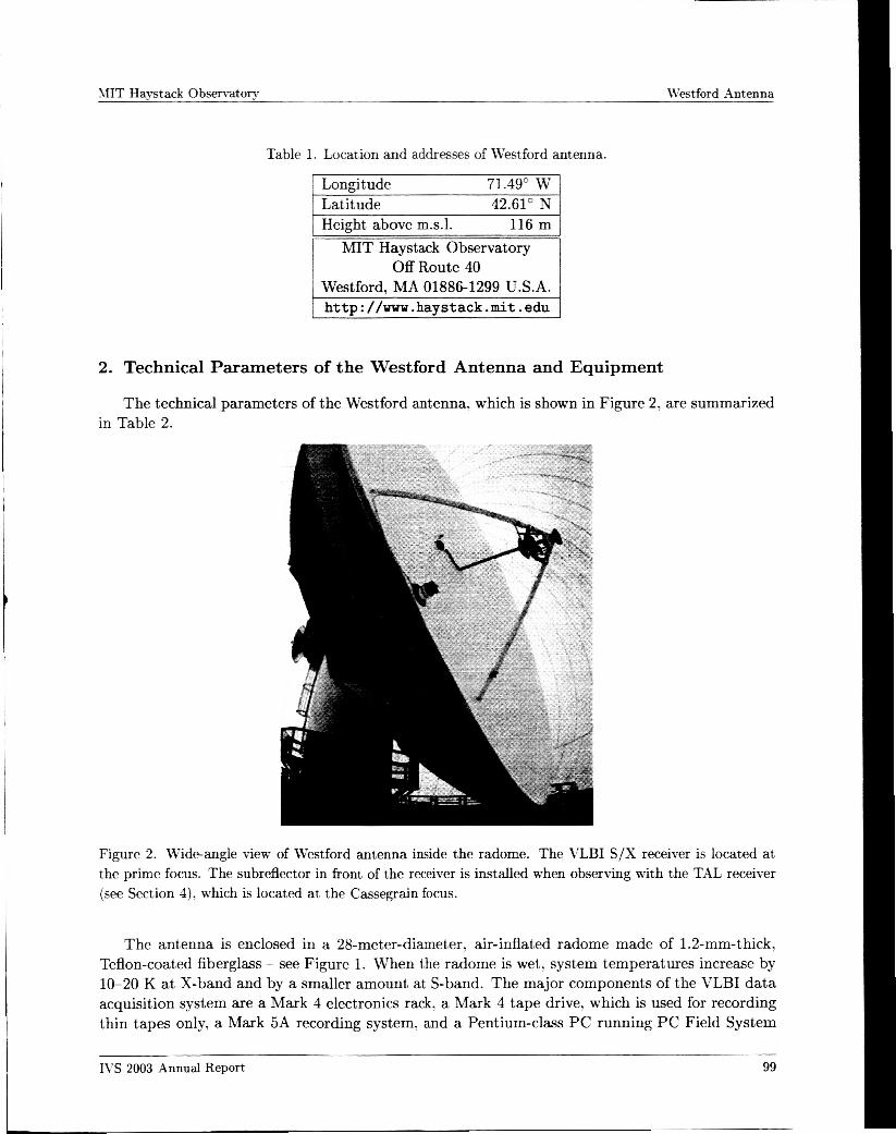
The technical parameters of the Westford antenna, which is shown in Figure 2, are summarized in Table 2.
Figure 2. P deangle view of Westford antenna inside the radome. The VLBI S/X receiver is located at the prime focus. The subreflector in front of the receiver is installed when observing with the TAL receiver (see Section 4), which is located at the Cassegrain focus.
The antenna is enclosed in a 28-meter-diameter, air-inflated radome made of 1.2-mm-thick, Teflon-coated fiberglass - see Figure 1. When the radome is wet, system temperatures increase by 10-20 K at X-band and by a smaller amount at S-band. The major components of the VLBI data acquisition system are a Mark 4 electronics rack, a Mark 4 tape drive, which is used for recording thin tapes only, a Mark 5A recording system, and a Pentium-class PC running PC Field System
IVS 2003 Annual Report 99
Westford Antenna MIT Haystack Observatory
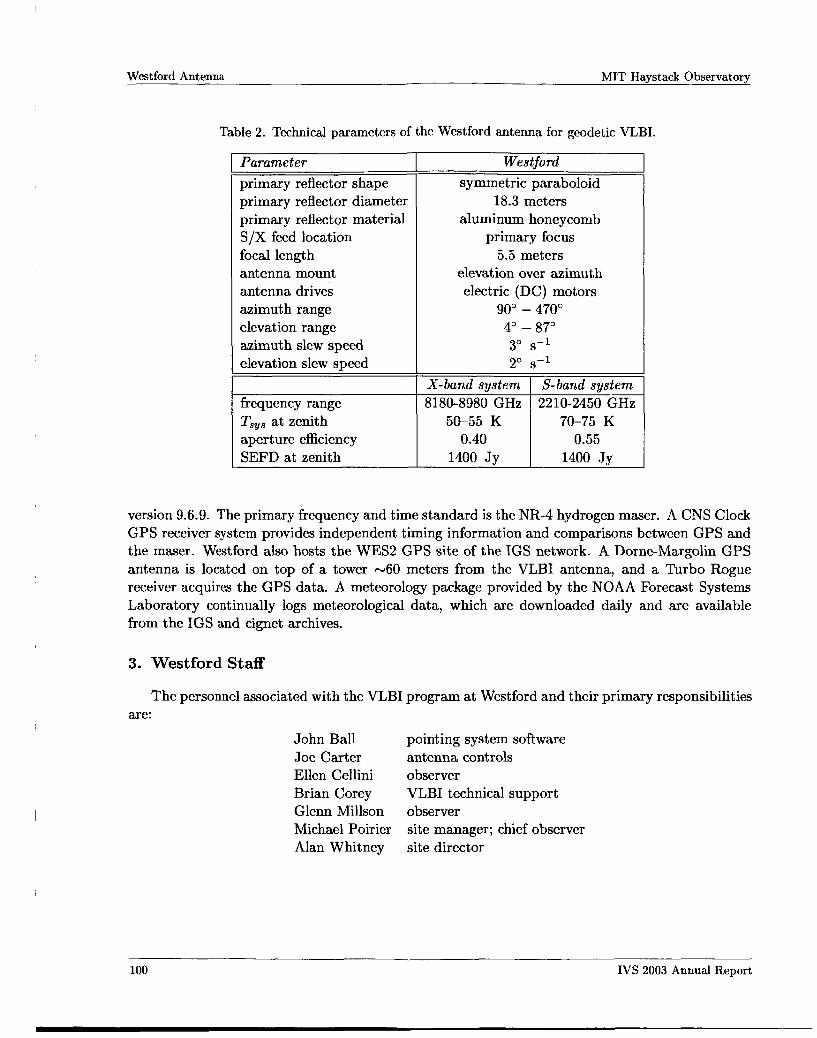
Table 2. Technical parameters of the Westford antenna for geodetic VLBI. ~~ ~
Parameter primary reflector shape primary reflector diameter primary reflector material S/X feed location focal length antenna mount antenna drives azimuth range elevation range azimuth slew speed elevation slew meed
Westford symmetric paraboloid
18.3 meters aluminum honeycomb
primary focus 5.5 meters
elevation over azimuth electric (DC) motors
90" - 470" 4" - 87" 3" s-l 2" s-l
frequency range Tsys at zenith 5&55 K 70-75 K aperture efficiency SEFD at zenith 1400 Jv 1400 Jv
version 9.6.9. The primary frequency and time standard is the NR-4 hydrogen maser. A CNS Clock GPS receiver system provides independent timing information and comparisons between GPS and the maser. Westford also hosts the WES2 GPS site of the IGS network. A Dorne-Margolin GPS antenna is located on top of a tower -60 meters from the VLBI antenna, and a Turbo Rogue receiver acquires the GPS data. A meteorology package provided by the NOAA Forecast Systems Laboratory continually logs meteorological data, which are downloaded daily and are available from the IGS and cignet archives.
3. Westford Staff
The personnel associated with the VLBI program at Westford and their primary responsibilities are:
John Ball pointing system software Joe Carter antenna controls Ellen Cellini observer Brian Corey VLBI technical support Glenn Millson observer Michael Poirier Alan Whitney site director
site manager; chief observer
100 IVS 2003 Annual Report
MIT Haystack Observatory Westford Antenna
4. Status of the Westford Antenna
During the period 2003 January 1 - 2003 December 31, Westford participated in a total of 71 24hour geodetic experiments. Westford participated regularly in the IVSR1, IVSR&D, and RD-VLBA series of geodetic experiments, as well as four IVST2 sessions and various fringe tests and e-VLBI experiments.
A Mark 5A recorder was installed at Westford in June 2003, as a replacement for the Mark 5P prototype used over the preceding year in occasional engineering tests and e-VLBI experiments. The Mark 5A has been used to record all geodetic sessions since June, with the exception of the RD-VLBA experiments, which are still recorded on tape.
There have been no significant equipment failures during this operational period. Use of the Westford antenna is shared with the Terrestrial Air Link (TAL) Program operated
by the MIT Lincoln Laboratory. In this project Westford serves as the receiving end on a 42- km-long terrestrial air link designed to study atmospheric effects on the propagation of wideband communications signals at 20 GHz.
5. e-VLBI Development at Westford
Westford continues to play a key role in the development of e-VLBI. In 2003, a number of e-VLBI demonstration experiments were carried out. Among them was a Kashima (Japan) to Westford UT1 experiment where data were recorded at Kashima and Westford on the K5 system, as well as on the Mark 5A system at Westford. Data were transferred via e-VLBI in both directions, with the necessary format conversion h m K5 to Mark 5A format done via software. Correlation was done both on a software correlator in Japan and the Mark 4 correlator at Haystack. Data from the Haystack correlator were transferred to NASA/GSFC for analysis of the UT1 results. All of this was done in less than 22 hours, from data collection to final results!
6. Outlook
We anticipate Westford will be able to participate in the 72 24hour geodetic experiments that are scheduled for Westford in 2004. More e-VLBI experiments are also planned for 2004.
IVS 2003 Annual Report 101


![CHAPTER 5 Multiband Reflector Antennas · Cassegrain antenna with FSS subreflector [1, 2]. Disadvantages of with this design include the loss associated with the FSS subreflector](https://img.pdfslide.us/doc/110x75/6122458fd4055649906f8c44/chapter-5-multiband-reflector-antennas-cassegrain-antenna-with-fss-subreflector.jpg)