Embed Size (px)
Citation preview
Western Electricity Coordinating Council
Western Interconnection Synchrophasor Program (WISP)
Mike Bianco, Program Manager, [email protected]
Vahid Madani, Program Lead, PG&[email protected]
NASPI Work Group MeetingOctober 5-6, 2010
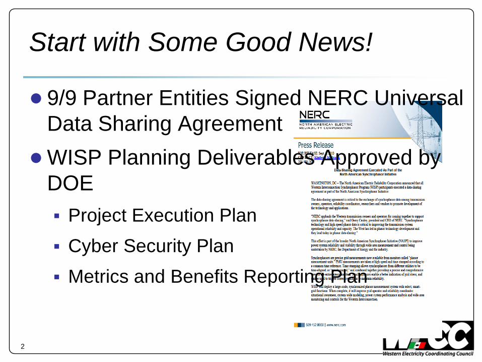
Start with Some Good News!
● 9/9 Partner Entities Signed NERC Universal Data Sharing Agreement
●WISP Planning Deliverables Approved by DOE Project Execution Plan Cyber Security Plan Metrics and Benefits Reporting Plan
2
Program Participants
● WECC Sponsorship and Delivery Management Mark Maher, WECC COO [email protected] Linda Perez, WECC Managing Director of RC & IT [email protected] Vickie VanZandt [email protected] Mike Bianco [email protected] Jim Dow [email protected]
● Partners 9 cost share partners; 11 additional participating entities throughout
West
● Academic and Other Montana Tech, the University of Wyoming and Pacific
Northwest National Laboratory
3
WISP Funding Overview
● 5-Yr Grant (3-yr deployment objective) –WECC awarded $54M
●Total program cost $108M
● $54M in cost share match from nine partner entities including WECC
● Largest of 10 Synchrophasor Projects
4
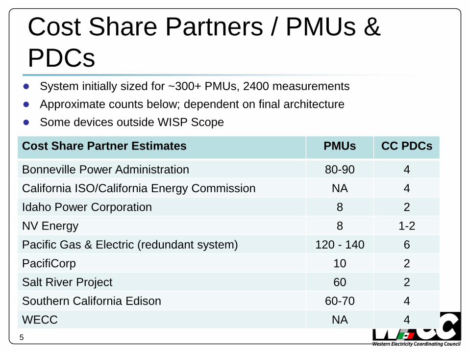
Cost Share Partners / PMUs & PDCs● System initially sized for ~300+ PMUs, 2400 measurements● Approximate counts below; dependent on final architecture● Some devices outside WISP Scope
5
Cost Share Partner Estimates PMUs CC PDCs
Bonneville Power Administration 80-90 4California ISO/California Energy Commission NA 4Idaho Power Corporation 8 2NV Energy 8 1-2Pacific Gas & Electric (redundant system) 120 - 140 6PacifiCorp 10 2Salt River Project 60 2Southern California Edison 60-70 4WECC NA 4
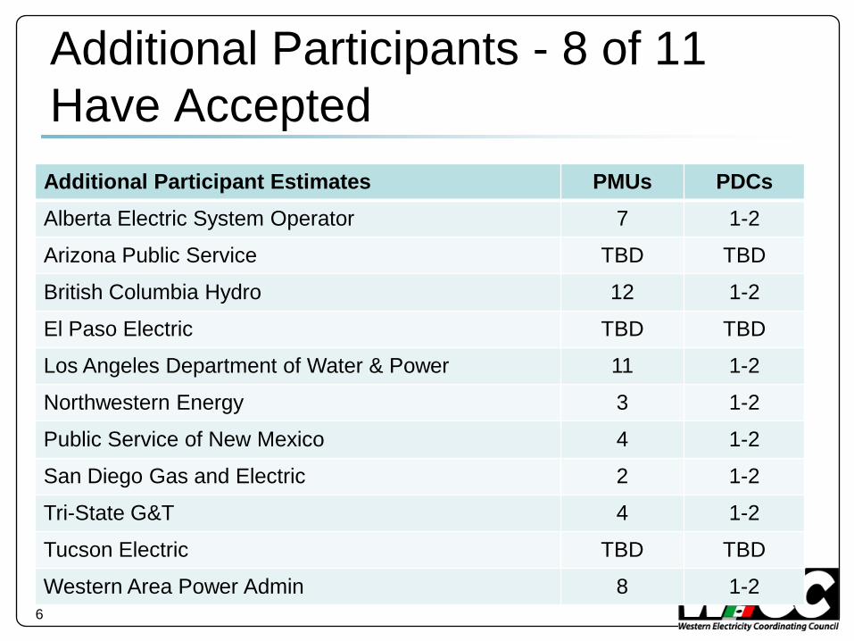
Additional Participants - 8 of 11 Have Accepted
6
Additional Participant Estimates PMUs PDCsAlberta Electric System Operator 7 1-2
Arizona Public Service TBD TBD
British Columbia Hydro 12 1-2
El Paso Electric TBD TBD
Los Angeles Department of Water & Power 11 1-2
Northwestern Energy 3 1-2
Public Service of New Mexico 4 1-2
San Diego Gas and Electric 2 1-2
Tri-State G&T 4 1-2
Tucson Electric TBD TBD
Western Area Power Admin 8 1-2
7
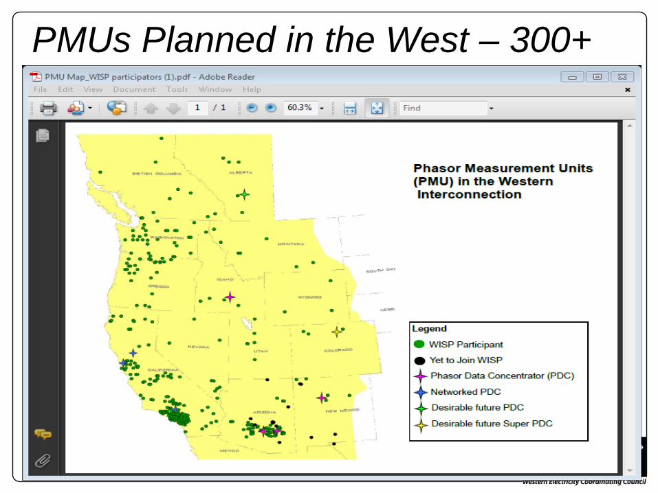
PMUs Planned in the West – 300+
Project Infrastructure Scope
● 300+ PMUs, 2400 signals, 50+ PDCs
● New Wide Area Network Managed telecommunications network for synchrophasor data
transport throughout the West
Aligns with NASPInet specifications
● Field Communications Partners extension of local area and campus networks
● Data Center IT Infrastructure Four new IT environments planned at WECC
● Phasor Gateways More planning and collaboration w/NASPI is required
8
PDCs
Redundant configuration planned at each partner and each WECC RC Key functionality includes
− Concentration (aggregation and time alignment) of C37.118-2005 frames
− Initially able to support approximately 300 PMUs, 2400 synchrophasors, 300 frequency and frequency rate of change values
− Scalable up to 120 frames/sec− Tools to assist in configuration and maintenance
and operation9
WISP Applications Scope
● Wide Area Situational Awareness
● General and rate-of-change monitoring & alarming
● Phase angle monitoring
● Voltage stability
● Oscillation detection, energy, damping estimate and mode meter
● Wide Area Shared View
● Event location & analysis
● System performance baselining
● System probing test monitoring
● State Estimation/Model Validation
10
COTS Approach – Minimal Customization Planned
WISP Cyber Security Guidelines● WECC and partners will comply with all applicable cyber security
standards
Minimum standard is NERC CIP
Leveraging NIST 7628 Risk Assessment Framework
Leveraging Department of Homeland Security: Cyber Security Procurement Language for Control Systems
● WECC and partners collaborating on an end to end synchrophasor system risk assessment
● Partners to determine how their synchrophasor equipment will be deployed and secured within the framework of the risk assessment and mitigating controls
● WECC may refuse data from a source that is deemed to present an unacceptable cyber security risk
11
Data Communications Approach
● What are you doing to assure interoperability? Leveraging current data transport standards – C37.118-2005
Work with NASPI PSTT on naming conventions
Define and develop a PMU / PDC Registry
● How will you test the effectiveness and security of your synchrophasor communications system? Coordinated testing with participants
− Connectivity testing
− Data validation testing
− Load and performance testing
− High-availability testing
− Validation of end to end security controls12
What else should we know about your project?● What are the most challenging things about your
project? End to end cyber security approach Balancing spend and reimbursement curve Interoperability validation Testing and certification
● What are the biggest challenges in resolving architecture for communications and data flow? Concerns about original partner budget commitments not
covering high-availability and critical asset implementation Predicting C37.118 and 61850 harmonization timeline
and migration strategy
13
What else should we know about your project?● Other useful information to share?
PG&E Approach for Proof of Concept and Validation
Collective Experience
● What can NASPI do to support your project? Facilitate collaboration on phasor gateway development and
implementation
Further define the implementation strategy for NASPInet – what do we collectively want to achieve next 2.5 years
Collaboration on Registry Specifications
PDC testing & certification requirements; PDC interoperability testing
Data archival requirements14
Key Accomplishments● DOE planning deliverables completed
● PMU placement criteria completed
● Draft business requirements completed
● Draft system architecture specifications completed
● Draft oscillation and detection requirements completed
● WAN specifications completed
● WAN, PDCs and Applications RFI efforts completed
● 8/11 additional entities have accepted WECC’s invitation to participate
15
Key Tasks in Progress
● WISP integrated schedule definition and critical path analysis
● Application and PDC RFP development
● WAN RFP development
● Cyber security requirements
● Oscillation detection design specifications
● WECC IT infrastructure technical requirements and test environment design
● WECC data center expansion design16
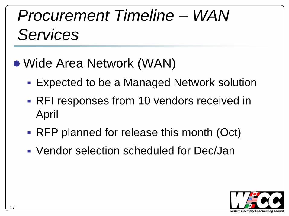
17
●Wide Area Network (WAN) Expected to be a Managed Network solution RFI responses from 10 vendors received in
April RFP planned for release this month (Oct) Vendor selection scheduled for Dec/Jan
Procurement Timeline – WAN Services
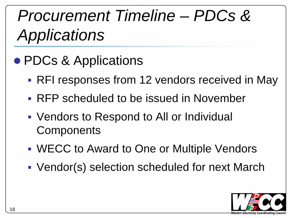
18
●PDCs & Applications RFI responses from 12 vendors received in May RFP scheduled to be issued in November Vendors to Respond to All or Individual
Components WECC to Award to One or Multiple Vendors Vendor(s) selection scheduled for next March
Procurement Timeline – PDCs & Applications
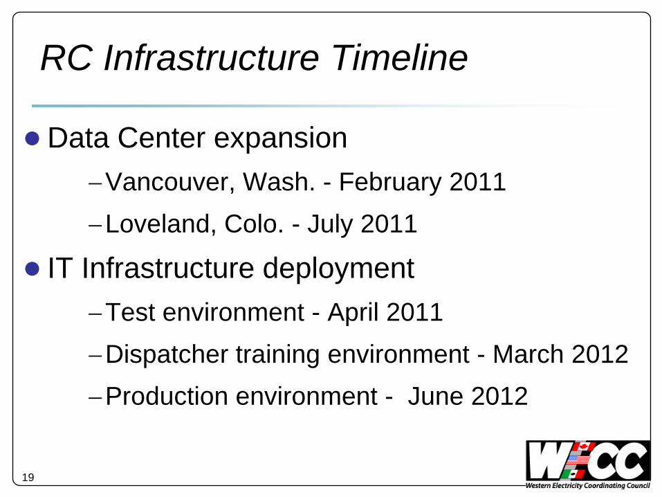
19
●Data Center expansion−Vancouver, Wash. - February 2011−Loveland, Colo. - July 2011
● IT Infrastructure deployment−Test environment - April 2011−Dispatcher training environment - March 2012−Production environment - June 2012
RC Infrastructure Timeline
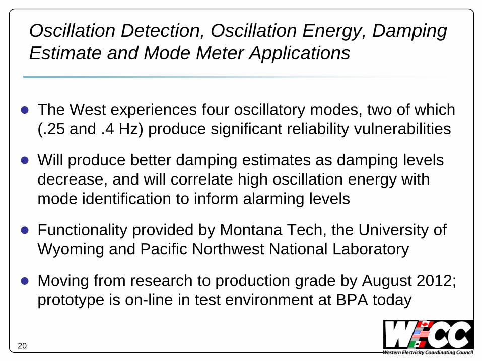
Oscillation Detection, Oscillation Energy, Damping Estimate and Mode Meter Applications
● The West experiences four oscillatory modes, two of which (.25 and .4 Hz) produce significant reliability vulnerabilities
● Will produce better damping estimates as damping levels decrease, and will correlate high oscillation energy with mode identification to inform alarming levels
● Functionality provided by Montana Tech, the University of Wyoming and Pacific Northwest National Laboratory
● Moving from research to production grade by August 2012; prototype is on-line in test environment at BPA today
20
Voltage Stability
● West has voltage stability vulnerabilities in major load centers; high path loadings also produce voltage stability concerns
● Voltage stability will be addressed by a combination of measurement-based and model-based tools
● Voltage displays Geographical view of voltage contours in the system
Voltage trends
Display reactive margin at a bus (estimated or calculated by model)
● Reactive Reserve tool Calculate and geographically display dynamic and
static reactive reserves21
Voltage Stability – PV-Curves
● Determine and display PV nose curves based on current topology
Operating point on the nose curve
Slope of curve (dV/dP) and margin to collapse point at operating point
Rate of change of slope as operating point moves
● Calculate PV curve for current operating state and contingency based on a state estimator model
● Alarm on slope, rate of change of slope and margin to collapse point
22
Power System Performance Baselining● Establishing seasonal norms for phase angles
● Baseline system frequency response, distribution of governor response, and impact of wind generation on system frequency performance
● Baseline oscillation damping – mode frequency and damping, mode shapes, oscillation energy, detecting and fixing forced oscillations, benchmark system models
● Deploy engineering tool to detect and study grid disturbances and unusual system conditions – outages, oscillations, power plant control failures
23
Phase Angle Displays and Alarms
● Phase angles across an interconnection indicate transmission system stress
● Baseline studies will establish seasonal norms for phase angles in the West
● Phase angle displays present phase angle in relation to the limits and historic norms and recent trends (last 10-15 min)
● Alarms notify operators when phase angles exceed safe operating limits; decision support tools to be included
24
System and Component Model Validation
● Accuracy of system and component models affects the precision of safe operating limits determined by off-line studies
● Better models may allow relaxation or tightening of operating limits where appropriate
● Synchrophasor data is compared against simulated model behavior to make correction in model parameters
● Baselining of system behavior is used to identify areas where models may need to be improved or off-line studies need to be expanded
25
WASA Shared View● Common views of west-wide reliability available to all
participants
Facilitates a simultaneous look at the same screens/ information by RCs and System Operators
Western Interconnection and four regional views planned Features planned:
Selectable, pre-configured views
Mode meter display with the four primary WECC oscillatory modes
Reactive reserve display, pre-defined reactive reserve groups
Pre-defined trends for key facilities (to capture oscillations)
Alarm indicators to draw users attention26


![NERC - Western Electricity Coordinating Council - Western ... NERC ERO CMEP-I…Translate this page%PDF-1.5 %âãÏÓ 9554 0 obj > endobj 9564 0 obj >/Filter/FlateDecode/ID[]/Index[9554](https://img.pdfslide.us/doc/110x75/5adae5b47f8b9a6d7e8d4b51/nerc-western-electricity-coordinating-council-western-nerc-ero-cmep-itranslate.jpg)