Embed Size (px)
Citation preview
High efficiency wall-mounted gas-fired boilers
Cazane murale pe gaz cu randament ridicat
Installer’s and User’s Instructions
Instruc^iuni de utilizare si instalare
BAXI S.p.A., unul dintre liderii europeni in produc^ia de centrale termicesi accesorii pentru uz casnic ( boilere de perete, de pardoseala,¶nc™lzitoare electrice de apa) a ob^inut certificatul de calitate QSCconform normelor UNI EN ISO 9001. Acest certificat garanteaz™ caSistemul de Calitate aplicat de BAXI S.p.A. fabrica din Bassano delGrappa, unde cazanul a fost produs, este conform standardelor UNIEN ISO 9001, care sunt stricte si se refera la toate procesele tehnologicesi la tot personalul implicat in produc^ie si distribu^ie.
BAXI S.p.A., one of the leading European enterprises to produce centralheating and hot water devices for domestic use (wall-mounted gas-operated boilers, floor-standing boilers, electrical water-heaters and steelheating plates) has obtained the CSQ certificate of conformity to theUNI EN ISO 9001 norms. This certificate guarantees that the QualitySystem applied at the BAXI S.p.A. factory in Bassano del Grappa, whereyour boiler was produced, meets the standards of the UNI EN ISO 9001norm, which is the strictest and concerns all organization stages andoperating personnel involved in the production and distribution processes. UNI EN ISO 9001
CERTIFICAZIONE DEI SISTEMIQUALITA' DELLE AZIENDE
Stimate client
Suntem convin`i ca noul produs BAXI vaveni in ¶nt™mpinarea cerin^elordumneavoastr™.
Cump™r<nd un produs BAXI asteptariledumneavoastr™ vor fi satisf™cute:func^ionare buna, simplu si u`or de utilizat.
Citi^i aceste instruc^iuni cu aten^ie: ve^i g™siaici informa^ii foarte utile, care va vor ajutasa porni^i si sa utiliza^i cazanul corect sieficient.
Nu lasati par^i de ambalaj (plastic, polistiren etc) la indemanacopiilor at<t timp cat acestea pot fi considerate periculoase.
Dear Customer,
We are sure your new boiler will comply withall your requirements.
Purchasing one of the BAXI products satisfiesyour expectations: good functioning, simplicityand ease of use.
Do not dispose of this booklet without readingit: you can find here some very usefulinformation, which will help you to run yourboiler correctly and efficiently.
Do not leave any parts of the packaging (plastic bags, polystyrene, etc.)within children’s reach as they are a potential source of danger.
BAXI S.p.A. attests that these models of boiler bear the CEmark in compliance with the basic requirements as laid downin the following Directives:- Gas Directive 90/396/CEE- Performance Directive 92/42/CEE- Electromagnetic Compatibility Directive 89/336/CEE- Low Voltage Directive 73/23/CEE
BAXI S.p.A
_ Centrale termice (cazane) murale cucombustibil gaz
_ Centrale termice (cazane) de podea cucombustibil gaz
_ ¶nc™lzitoare electrice de apa
_ ¶nc™lzitoare pe gaz de apa
_ Accesorii de baie din inox
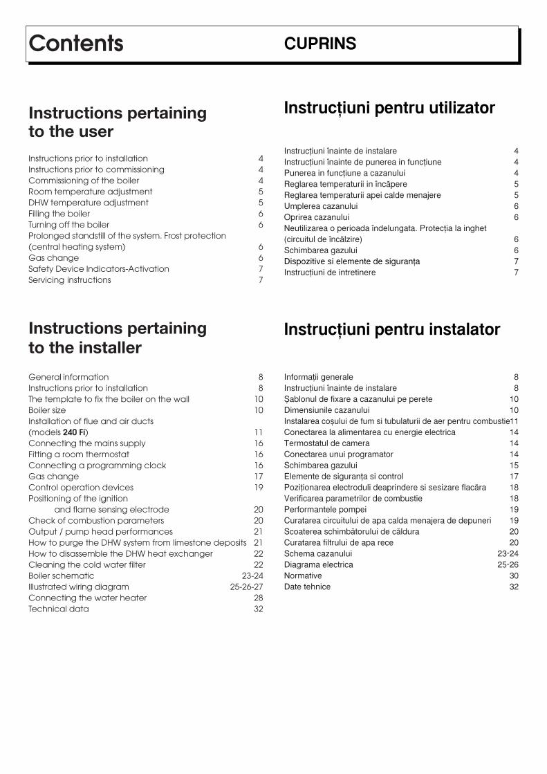
CUPRINS
Instruc^iuni pentru utilizator
Instruc^iuni ¶nainte de instalare 4Instruc^iuni ¶nainte de punerea in func^iune 4Punerea in func^iune a cazanului 4Reglarea temperaturii in ¶nc™pere 5Reglarea temperaturii apei calde menajere 5Umplerea cazanului 6Oprirea cazanului 6Neutilizarea o perioada ¶ndelungata. Protec^ia la inghet(circuitul de ¶nc™lzire) 6Schimbarea gazului 6Dispozitive si elemente de siguran^a 7Instruc^iuni de intretinere 7
Instruc^iuni pentru instalator
Informa^ii generale 8Instruc^iuni ¶nainte de instalare 8~ablonul de fixare a cazanului pe perete 10Dimensiunile cazanului 10Instalarea co`ului de fum si tubulaturii de aer pentru combustie11Conectarea la alimentarea cu energie electrica 14Termostatul de camera 14Conectarea unui programator 14Schimbarea gazului 15Elemente de siguran^a si control 17Pozi^ionarea electroduli deaprindere si sesizare flac™ra 18Verificarea parametrilor de combustie 18Performantele pompei 19Curatarea circuitului de apa calda menajera de depuneri 19Scoaterea schimb™torului de c™ldura 20Curatarea filtrului de apa rece 20Schema cazanului 23-24Diagrama electrica 25-26Normative 30Date tehnice 32
Contents
Instructions pertainingto the userInstructions prior to installation 4Instructions prior to commissioning 4Commissioning of the boiler 4Room temperature adjustment 5DHW temperature adjustment 5Filling the boiler 6Turning off the boiler 6Prolonged standstill of the system. Frost protection(central heating system) 6Gas change 6Safety Device Indicators-Activation 7Servicing instructions 7
Instructions pertainingto the installer
General information 8Instructions prior to installation 8The template to fix the boiler on the wall 10Boiler size 10Installation of flue and air ducts(models 240 Fi) 11Connecting the mains supply 16Fitting a room thermostat 16Connecting a programming clock 16Gas change 17Control operation devices 19Positioning of the ignition
and flame sensing electrode 20Check of combustion parameters 20Output / pump head performances 21How to purge the DHW system from limestone deposits 21How to disassemble the DHW heat exchanger 22Cleaning the cold water filter 22Boiler schematic 23-24Illustrated wiring diagram 25-26-27Connecting the water heater 28Technical data 32
4
Instruc^iuni ¶nainte deinstalareAcest produs este conceput pentru ¶nc™lzirea apei la o tempera-tura mai mica dec<t cea de fierbere, la presiunea atmosferica.Centrala termica trebuie conectata la sistemul de ¶nc™lzire si laalimentarea cu apa calda menajera in concordanta cu puterea siperformantele lui.Echipamentul trebuie sa fie instalat de personal calificat si totodat™trebuie ¶ndeplinite urm™toarele condi^ii
a) curatarea tuturor ^evilor pentru a ¶ndep™rta toate impuritatile;
b) centrala sa fie alimentat cu tipul de gaz adecvat. Pentru maimulte detalii vede^i ambalajul precum si eticheta de pe produsulin sine.
c) Co`ul de fum trebuie sa fie situat in apropiere, sa nu fie obturatsi sa nu existe ie`iri ale altor aparate cu gaz pe acela`i cos,dec<t in cazul in care co`ul este proiectat special pentruevacuarea gazelor / fumului de la mai multe echipamente, inconcordanta cu regulile si legile in vigoare.
d) Daca centrala se conecteaz™ la o evacuare mai veche,curatarea acestuia trebuie f™cuta cu grija pentru ca reziduurilecombustibile pot ajunge, in timpul func^ionarii, la boiler si saobtureze canalul de fum conduc<nd la situa^ii periculoase.
Instruc^iuni ¶nainte de punereain func^iunePrima aprindere a boilerului trebuie executata de c™tre untehnician autorizat.Nerespectarea urm™toarelor instruc^iuni atrage dup™ sinepierderea garan^iei.a) parametrii boilerului (electricitate, apa, gaz) trebuie sa
corespunda cu sistemul de alimentare existent;b) instalarea sa fie conforma cu legile si normele in vigoare;c) alimentarea cu energie sa fie aproape si sa existe
impamantarea.Verific™rile care preced punerea in func^iune trebuie efectuate depersonal autorizat in acest sens.Punerea in func^iune de personal neautorizat conduce la pierdereagaran^iei. ¶nainte de punerea in func^iune Indepartati plasticulprotector de pe echipament. Nu folosi^i scule sau detergen^iabrazivi pentru a nu zg<ria suprafe^ele vopsite.
Punerea in func^iune acazanuluiPentru aprinderea arz™torului proceda^i astfel:1) centrala sa fie conectata la sistemul de alimentare cu energie
electrica;2) Robinetul de alimentare cu gaz trebuie sa fie in pozi^ia deschis3) roti^i butonul (1) pentru selectarea pozi^iei de vara ( ) adic™
numai apa calda menajera (soarele pe panou) sau pozi^ia deiarna ( ) adic™ apa calda menajera si ¶nc™lzire (stelu^a pepanou);
4) roti^i butoanele 5 (pentru ¶nc™lzire) si 6 (apa calda menajera)pentru a putea aprinde arz™torul principal.
In pozi^ia vara ( ) arz™torul se va aprinde si pompa va fi infunc^iune numai daca se cere apa calda.
Instructions pertaining to the user - INSTRUCÿIUNI PENTRU UTILIZATOR
Instructions prior toinstallationThis boiler is designed to heat water at a lower than boiling temperatureat atmospheric pressure. The boiler must be connected to a central heatingsystem and to a domestic hot water supply system in compliance withits performances and output power.Have the boiler installed by a Qualified Service Engineer and ensure thefollowing operations are accomplished:
a) accurate purging of the whole pipework in order to remove anydeposits.
b) careful checking that the boiler is fit for operation with the type ofgas available. For more details see the notice on the packaging andthe label on the appliance itself.
c) that the terminal is not obstructed and that no other appliance exhaustgases are expelled through the same flue duct, unless the flue isespecially designed to collect the exhaust gas coming from more thanone appliance, in conformity with the laws and regulations in force.
d) careful checking that, in case the flue has been connected to pre-existing flue ducts, thorough cleaning has been carried out in thatresidual combustion products may come off during operation of theboiler and obstruct the flue duct thus engendering dangerous situations.
Instructions prior tocommissioningInitial lighting of the boiler must be carried out by a licensed technician.Ensure the following operations are carried out:a) compliance of boiler parameters with (electricity, water, gas) supply
systems settings.b) compliance of installation with the laws and regulations in force.c) appropriate connection to the power supply and grounding of the
appliance.
Failure to observe the above will render the guarantee null and void.Prior to commissioning remove the protective plastic coating from theunit. Do not use any tools or abrasive detergents as you may spoil thepainted surfaces.
Commissioningof the boilerTo correctly light the burner proceed as follows:1) provide power supply to the boiler;2) open the gas cock;3) turn the selector switch (1) to set the boiler on summertime ( ) or
wintertime ( ) operation;4) turn the central heating (5) and domestic hot water (6) adjusting
controls in order to light the main burner.To increase temperature values turn the control clockwise andanticlockwise to decrease it.When on summertime operation ( ) the main burner and the pumpwill start running only when there is a call for hot water.
5
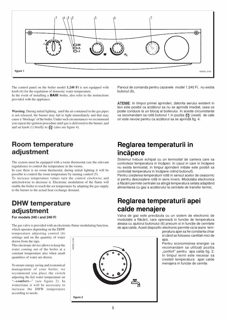
figure 1
Panoul de comanda pentru cazanele model 1.240 Fi, nu existabutonul (6),
ATENÿIE: In timpul primei aprinderi, datorita aerului existent in^evi este posibil ca arz™torul sa nu se aprind™ imediat, ceea cepoate conduce la un blocaj al boilerului. In aceste circumstan^eva recomandam sa roti^i butonul 1 in pozi^ia ( ) (reset) de cateori este nevoie pentru ca arz™torul sa se aprind™ fig. 4.
Reglarea temperaturii in¶nc™pereSistemul trebuie echipat cu un termostat de camera care sacontroleze temperatura in ¶nc™peri. In cazul in care in ¶nc™perenu exista termostat, in timpul aprinderii ini^iale este posibil sacontrola^i temperatura in ¶nc™pere rotind butonul5.Pentru cre`terea temperaturii roti^i in sensul acelor de ceasornicsi pentru descre`tere roti^i in sens invers. Modula^ia electronicaa fl™c™rii permite centralei sa ating™ temperatura setata adapt<ndalimentarea cu gaz a arz™torului la cerin^ele de transfer termic.
Reglarea temperaturii apeicalde menajereValva de gaz este prev™zuta cu un sistem de electronic demodula^ie a fl™c™rii, care opereaz™ in func^ie de temperaturaaleasa cu ajutorul butonului (6) precum si in func^ie de cerin^elede apa calda. Acest dispozitiv electronic permite ca la ie`ire tem-
peratura apei sa fie constanta chiarsi c<nd se folosesc cantitati mici deapa.Pentru economisirea energiei varecomandam sa utiliza^i pozi^ia„confort” pentru apa calda fig. 2.In timpul iernii este necesar sacresteti temperatura apei caldemenajera in func^ie de cerin^e.
figure 2
000522_0100
The control panel on the boiler model 1.240 Fi is not equipped withknob (6) for the regulation of domestic water temperature.In the event of installing a BAXI boiler, also refer to the instructionsprovided with the appliance.
Warning: During initial lighting, until the air contained in the gas pipesis not released, the burner may fail to light immediately and that maycause a ‘blockage’ of the boiler. Under such circumstances we recommendyou repeat the ignition procedure until gas is delivered to the burner, andand set knob (1) briefly to ( ) (also see figure 4).
Room temperatureadjustmentThe system must be equipped with a room thermostat (see the relevantregulations) to control the temperature in the rooms.In case there is no room thermostat, during initial lighting it will bepossible to control the room temperature by turning control (5).To increase temperature values turn the control clockwise andanticlockwise to decrease it. Electronic modulation of the flame willenable the boiler to reach the set temperature by adapting the gas supplyto the burner to the actual heat exchange demand.
DHW temperatureadjustmentFor models 240 i and 240 Fi
The gas valve is provided with an electronic flame-modulating function,which operates depending on the DHWtemperature adjusting control (6)settings and on the quantity of waterdrawn from the taps.This electronic device allows to keep thewater coming out of the boiler at aconstant temperature also when smallquantities of water are drawn.
To ensure energy saving and economicalmanagement of your boiler, werecommend you place the switchadjusting the hot water temperature on“--comfort--” (see figure 2). Inwintertime it will be necessary toincrease the DHW temperatureaccording to needs.
0005
29_0
100
6
9909
2701
00
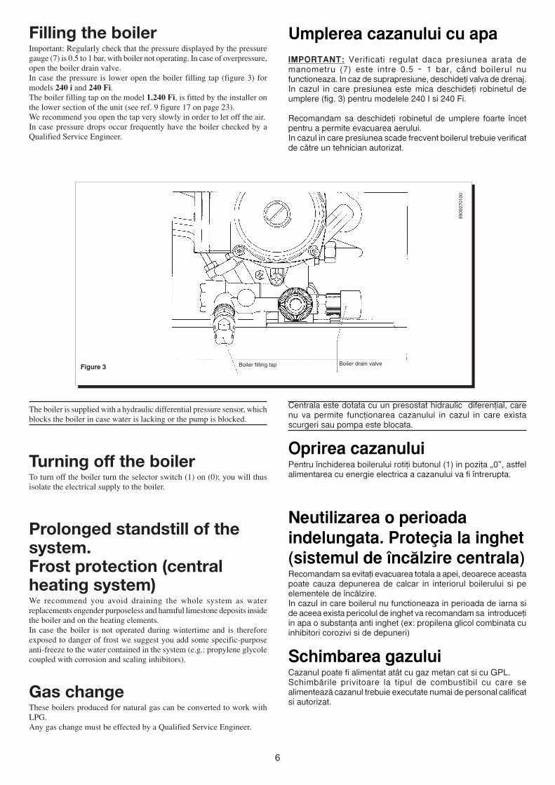
Umplerea cazanului cu apaIMPORTANT: Verificati regulat daca presiunea arata demanometru (7) este intre 0.5 – 1 bar, c<nd boilerul nufunctioneaza. In caz de suprapresiune, deschide^i valva de drenaj.In cazul in care presiunea este mica deschide^i robinetul deumplere (fig. 3) pentru modelele 240 I si 240 Fi.
Recomandam sa deschide^i robinetul de umplere foarte ¶ncetpentru a permite evacuarea aerului.In cazul in care presiunea scade frecvent boilerul trebuie verificatde c™tre un tehnician autorizat.
Boiler filling tap Boiler drain valveFigure 3
Centrala este dotata cu un presostat hidraulic diferen^ial, carenu va permite func^ionarea cazanului in cazul in care existascurgeri sau pompa este blocata.
Oprirea cazanuluiPentru ¶nchiderea boilerului roti^i butonul (1) in pozi^a „0”, astfelalimentarea cu energie electrica a cazanului va fi ¶ntrerupta.
Neutilizarea o perioadaindelungata. Prote≠ia la inghet(sistemul de ¶nc™lzire centrala)Recomandam sa evita^i evacuarea totala a apei, deoarece aceastapoate cauza depunerea de calcar in interiorul boilerului si peelementele de ¶nc™lzire.In cazul in care boilerul nu functioneaza in perioada de iarna side aceea exista pericolul de inghet va recomandam sa introduce^iin apa o substan^a anti inghet (ex: propilena glicol combinata cuinhibitori corozivi si de depuneri)
Schimbarea gazuluiCazanul poate fi alimentat at<t cu gaz metan cat si cu GPL.Schimb™rile privitoare la tipul de combustibil cu care sealimenteaz™ cazanul trebuie executate numai de personal calificatsi autorizat.
The boiler is supplied with a hydraulic differential pressure sensor, whichblocks the boiler in case water is lacking or the pump is blocked.
Turning off the boilerTo turn off the boiler turn the selector switch (1) on (0); you will thusisolate the electrical supply to the boiler.
Prolonged standstill of thesystem.Frost protection (centralheating system)We recommend you avoid draining the whole system as waterreplacements engender purposeless and harmful limestone deposits insidethe boiler and on the heating elements.In case the boiler is not operated during wintertime and is thereforeexposed to danger of frost we suggest you add some specific-purposeanti-freeze to the water contained in the system (e.g.: propylene glycolecoupled with corrosion and scaling inhibitors).
Gas changeThese boilers produced for natural gas can be converted to work withLPG.Any gas change must be effected by a Qualified Service Engineer.
Filling the boilerImportant: Regularly check that the pressure displayed by the pressuregauge (7) is 0.5 to 1 bar, with boiler not operating. In case of overpressure,open the boiler drain valve.In case the pressure is lower open the boiler filling tap (figure 3) formodels 240 i and 240 Fi.The boiler filling tap on the model 1.240 Fi, is fitted by the installer onthe lower section of the unit (see ref. 9 figure 17 on page 23).We recommend you open the tap very slowly in order to let off the air.In case pressure drops occur frequently have the boiler checked by aQualified Service Engineer.
7
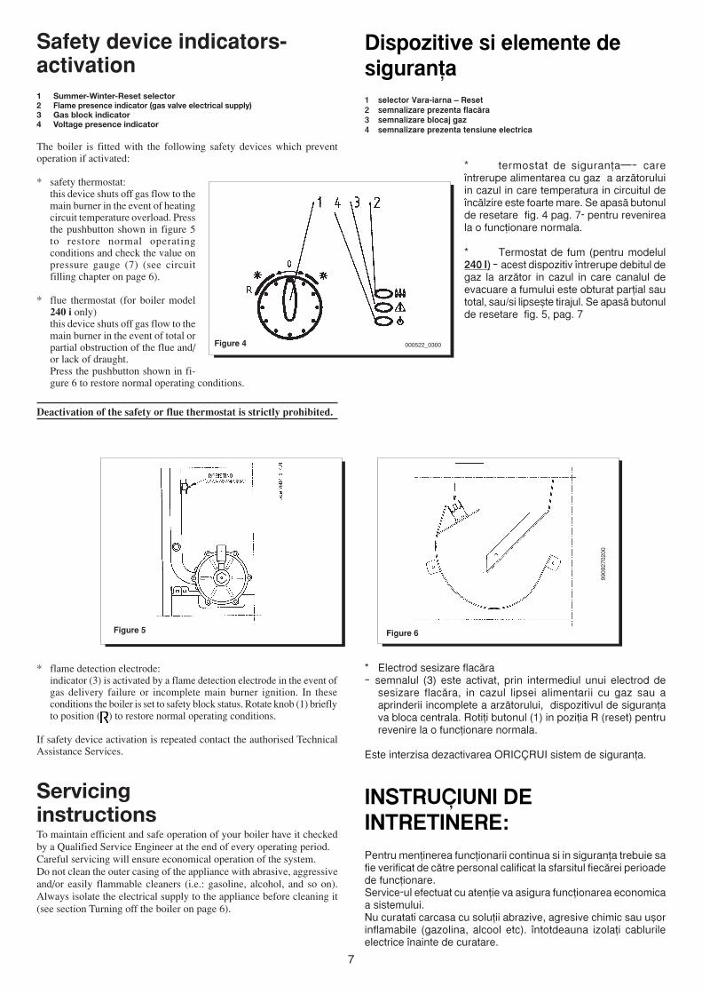
Dispozitive si elemente desiguran^a1 selector Vara-iarna – Reset2 semnalizare prezenta flac™ra3 semnalizare blocaj gaz4 semnalizare prezenta tensiune electrica
* termostat de siguran^a—– care¶ntrerupe alimentarea cu gaz a arz™toruluiin cazul in care temperatura in circuitul de¶nc™lzire este foarte mare. Se apas™ butonulde resetare fig. 4 pag. 7- pentru revenireala o func^ionare normala.
* Termostat de fum (pentru modelul240 I) – acest dispozitiv ¶ntrerupe debitul degaz la arz™tor in cazul in care canalul deevacuare a fumului este obturat par^ial sautotal, sau/si lipse`te tirajul. Se apas™ butonulde resetare fig. 5, pag. 7
Figure 4
Safety device indicators-activation1 Summer-Winter-Reset selector2 Flame presence indicator (gas valve electrical supply)3 Gas block indicator4 Voltage presence indicator
The boiler is fitted with the following safety devices which preventoperation if activated:
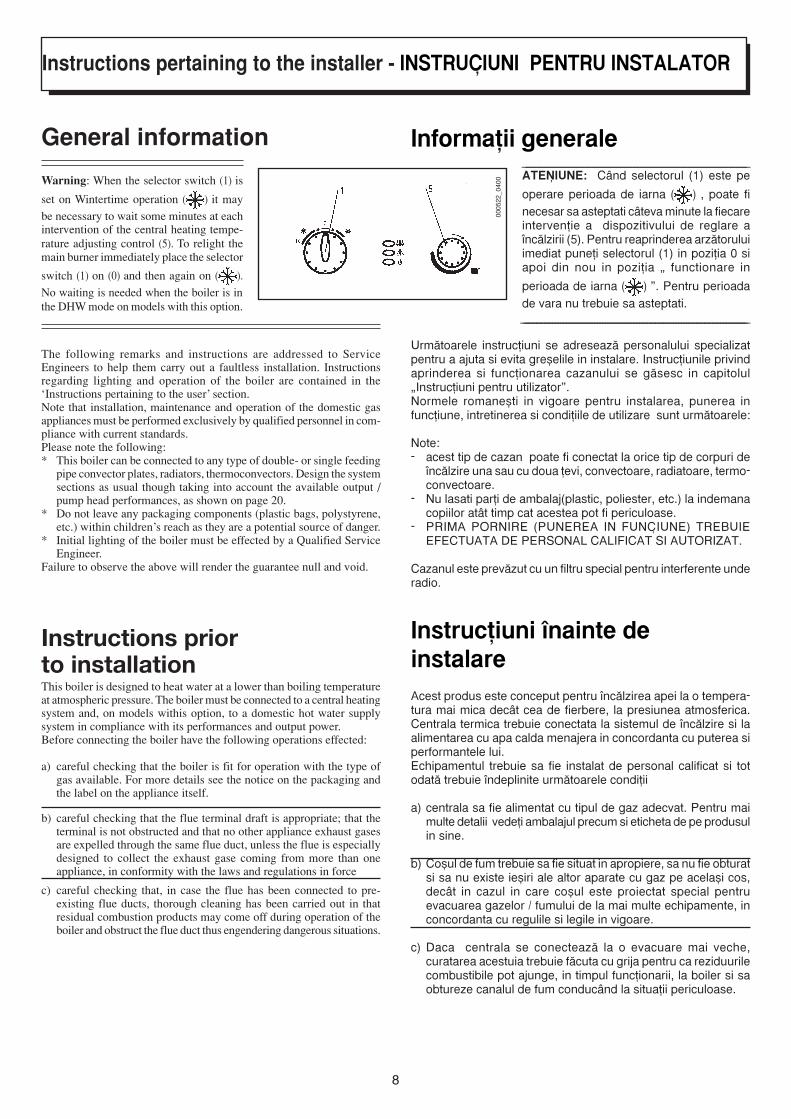
* safety thermostat:this device shuts off gas flow to themain burner in the event of heatingcircuit temperature overload. Pressthe pushbutton shown in figure 5to restore normal operatingconditions and check the value onpressure gauge (7) (see circuitfilling chapter on page 6).
* flue thermostat (for boiler model240 i only)this device shuts off gas flow to themain burner in the event of total orpartial obstruction of the flue and/or lack of draught.Press the pushbutton shown in fi-gure 6 to restore normal operating conditions.
Deactivation of the safety or flue thermostat is strictly prohibited.
Figure 5 Figure 6
9909
2702
00
* flame detection electrode:indicator (3) is activated by a flame detection electrode in the event ofgas delivery failure or incomplete main burner ignition. In theseconditions the boiler is set to safety block status. Rotate knob (1) brieflyto position ( ) to restore normal operating conditions.
If safety device activation is repeated contact the authorised TechnicalAssistance Services.
ServicinginstructionsTo maintain efficient and safe operation of your boiler have it checkedby a Qualified Service Engineer at the end of every operating period.Careful servicing will ensure economical operation of the system.Do not clean the outer casing of the appliance with abrasive, aggressiveand/or easily flammable cleaners (i.e.: gasoline, alcohol, and so on).Always isolate the electrical supply to the appliance before cleaning it(see section Turning off the boiler on page 6).
000522_0300
* Electrod sesizare flac™ra– semnalul (3) este activat, prin intermediul unui electrod de
sesizare flac™ra, in cazul lipsei alimentarii cu gaz sau aaprinderii incomplete a arz™torului, dispozitivul de siguran^ava bloca centrala. Roti^i butonul (1) in pozi^ia R (reset) pentrurevenire la o func^ionare normala.
Este interzisa dezactivarea ORIC¨RUI sistem de siguran^a.
INSTRUCÿIUNI DEINTRETINERE:Pentru men^inerea func^ionarii continua si in siguran^a trebuie safie verificat de c™tre personal calificat la sfarsitul fiec™rei perioadede func^ionare.Service-ul efectuat cu aten^ie va asigura func^ionarea economicaa sistemului.Nu curatati carcasa cu solu^ii abrazive, agresive chimic sau u`orinflamabile (gazolina, alcool etc). ¶ntotdeauna izola^i cablurileelectrice ¶nainte de curatare.
8
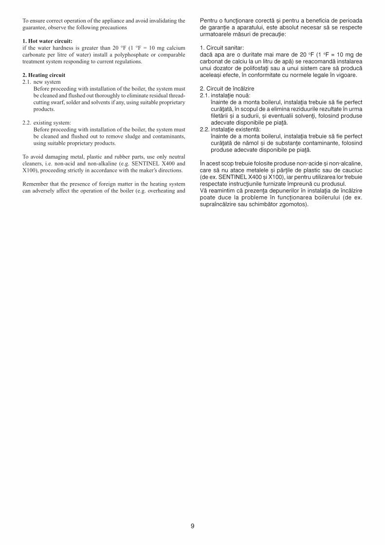
Informa^ii generale_____________________________________________________________ATENÿIUNE: C<nd selectorul (1) este pe
operare perioada de iarna ( ) , poate finecesar sa asteptati c<teva minute la fiecareinterven^ie a dispozitivului de reglare a¶nc™lzirii (5). Pentru reaprinderea arz™toruluiimediat pune^i selectorul (1) in pozi^ia 0 siapoi din nou in pozi^ia „ functionare in
perioada de iarna ( ) ”. Pentru perioadade vara nu trebuie sa asteptati. ______________________________________________________________________________________
Urm™toarele instruc^iuni se adreseaz™ personalului specializatpentru a ajuta si evita gre`elile in instalare. Instruc^iunile privindaprinderea si func^ionarea cazanului se g™sesc in capitolul„Instruc^iuni pentru utilizator”.Normele romane`ti in vigoare pentru instalarea, punerea infunc^iune, intretinerea si condi^iile de utilizare sunt urm™toarele:
Note:- acest tip de cazan poate fi conectat la orice tip de corpuri de
¶nc™lzire una sau cu doua ̂ evi, convectoare, radiatoare, termo-convectoare.
- Nu lasati par^i de ambalaj(plastic, poliester, etc.) la indemanacopiilor at<t timp cat acestea pot fi periculoase.
- PRIMA PORNIRE (PUNEREA IN FUNCÿIUNE) TREBUIEEFECTUATA DE PERSONAL CALIFICAT SI AUTORIZAT.
Cazanul este prev™zut cu un filtru special pentru interferente underadio.
Instruc^iuni ¶nainte deinstalareAcest produs este conceput pentru ¶nc™lzirea apei la o tempera-tura mai mica dec<t cea de fierbere, la presiunea atmosferica.Centrala termica trebuie conectata la sistemul de ¶nc™lzire si laalimentarea cu apa calda menajera in concordanta cu puterea siperformantele lui.Echipamentul trebuie sa fie instalat de personal calificat si totodat™ trebuie ¶ndeplinite urm™toarele condi^ii
a) centrala sa fie alimentat cu tipul de gaz adecvat. Pentru maimulte detalii vede^i ambalajul precum si eticheta de pe produsulin sine.
b) Co`ul de fum trebuie sa fie situat in apropiere, sa nu fie obturatsi sa nu existe ie`iri ale altor aparate cu gaz pe acela`i cos,dec<t in cazul in care co`ul este proiectat special pentruevacuarea gazelor / fumului de la mai multe echipamente, inconcordanta cu regulile si legile in vigoare.
c) Daca centrala se conecteaz™ la o evacuare mai veche,curatarea acestuia trebuie f™cuta cu grija pentru ca reziduurilecombustibile pot ajunge, in timpul func^ionarii, la boiler si saobtureze canalul de fum conduc<nd la situa^ii periculoase.
Instructions pertaining to the installer - INSTRUCÿIUNI PENTRU INSTALATOR
General information
Warning: When the selector switch (1) is
set on Wintertime operation ( ) it may
be necessary to wait some minutes at eachintervention of the central heating tempe-rature adjusting control (5). To relight themain burner immediately place the selector
switch (1) on (0) and then again on ( ).
No waiting is needed when the boiler is inthe DHW mode on models with this option.
The following remarks and instructions are addressed to ServiceEngineers to help them carry out a faultless installation. Instructionsregarding lighting and operation of the boiler are contained in the‘Instructions pertaining to the user’ section.Note that installation, maintenance and operation of the domestic gasappliances must be performed exclusively by qualified personnel in com-pliance with current standards.Please note the following:* This boiler can be connected to any type of double- or single feeding
pipe convector plates, radiators, thermoconvectors. Design the systemsections as usual though taking into account the available output /pump head performances, as shown on page 20.
* Do not leave any packaging components (plastic bags, polystyrene,etc.) within children’s reach as they are a potential source of danger.
* Initial lighting of the boiler must be effected by a Qualified ServiceEngineer.
Failure to observe the above will render the guarantee null and void.
Instructions priorto installationThis boiler is designed to heat water at a lower than boiling temperatureat atmospheric pressure. The boiler must be connected to a central heatingsystem and, on models withis option, to a domestic hot water supplysystem in compliance with its performances and output power.Before connecting the boiler have the following operations effected:
a) careful checking that the boiler is fit for operation with the type ofgas available. For more details see the notice on the packaging andthe label on the appliance itself.
b) careful checking that the flue terminal draft is appropriate; that theterminal is not obstructed and that no other appliance exhaust gasesare expelled through the same flue duct, unless the flue is especiallydesigned to collect the exhaust gase coming from more than oneappliance, in conformity with the laws and regulations in force
c) careful checking that, in case the flue has been connected to pre-existing flue ducts, thorough cleaning has been carried out in thatresidual combustion products may come off during operation of theboiler and obstruct the flue duct thus engendering dangerous situations.
0005
22_0
400
9
Pentru o func∑ionare corect™ `i pentru a beneficia de perioadade garan∑ie a aparatului, este absolut necesar s™ se respecteurmatoarele m™suri de precau∑ie:
1. Circuit sanitar:dac™ apa are o duritate mai mare de 20 oF (1 oF = 10 mg decarbonat de calciu la un litru de ap™) se reacomand™ instalareaunui dozator de polifosfa∑i sau a unui sistem care s™ produc™acelea`i efecte, ¶n conformitate cu normele legale ¶n vigoare.
2. Circuit de ¶nc™lzire2.1. instala∑ie nou™:
¶nainte de a monta boilerul, instala∑ia trebuie s™ fie perfectcur™∑at™, ¶n scopul de a elimina reziduurile rezultate ¶n urmafilet™rii `i a sudurii, `i eventualii solven∑i, folosind produseadecvate disponibile pe pia∑™.
2.2. instala∑ie existent™:¶nainte de a monta boilerul, instala∑ia trebuie s™ fie perfectcur™∑at™ de n™mol `i de substan∑e contaminante, folosindproduse adecvate disponibile pe pia∑™.
•n acest scop trebuie folosite produse non-acide ̀ i non-alcaline,care s™ nu atace metalele `i p™r∑ile de plastic sau de cauciuc(de ex. SENTINEL X400 ̀ i X100), iar pentru utilizarea lor trebuierespectate instruc∑iunile furnizate ¶mpreun™ cu produsul.V™ reamintim c™ prezen∑a depunerilor ¶n instala∑ia de ¶nc™lzirepoate duce la probleme ¶n func∑ionarea boilerului (de ex.supra¶nc™lzire sau schimb™tor zgomotos).
To ensure correct operation of the appliance and avoid invalidating theguarantee, observe the following precautions
1. Hot water circuit:if the water hardness is greater than 20 °F (1 °F = 10 mg calciumcarbonate per litre of water) install a polyphosphate or comparabletreatment system responding to current regulations.
2. Heating circuit2.1. new system
Before proceeding with installation of the boiler, the system mustbe cleaned and flushed out thoroughly to eliminate residual thread-cutting swarf, solder and solvents if any, using suitable proprietaryproducts.
2.2. existing system:Before proceeding with installation of the boiler, the system mustbe cleaned and flushed out to remove sludge and contaminants,using suitable proprietary products.
To avoid damaging metal, plastic and rubber parts, use only neutralcleaners, i.e. non-acid and non-alkaline (e.g. SENTINEL X400 andX100), proceeding strictly in accordance with the maker’s directions.
Remember that the presence of foreign matter in the heating systemcan adversely affect the operation of the boiler (e.g. overheating and
10
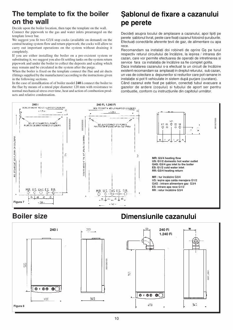
The template to fix the boileron the wallDecide upon the boiler location, then tape the template on the wall.Connect the pipework to the gas and water inlets prearranged on thetemplate lower bar.We suggest you fit two G3/4 stop cocks (available on demand) on thecentral heating system flow and return pipework; the cocks will allow tocarry out important operations on the system without draining itcompletely.If you are either installing the boiler on a pre-existent system orsubstituting it, we suggest you also fit settling tanks on the system returnpipework and under the boiler to collect the deposits and scaling whichmay remain and be circulated in the system after the purge.When the boiler is fixed on the template connect the flue and air ducts(fittings supplied by the manufacturer) according to the instructions givenin the following sections.In the case of installkation of of boiler model 240 i connect the boiler tothe flue by means of a mteal pipe diameter 120 mm with resistrance tonormal mechanical stress over time, heat and action of combustion prod-ucts and relative condensation.
0003
0305
00
Figura 7
MR: G3/4 heating flowUS: G1/2 domestic hot water outletGAS: G3/4 gas inlet to the boilerES: G1/2 cold water inletRR: G3/4 heating return
MR : tur ¶nc™lzire G3/4US: ie`ire apa calda menajera G1/2GAS : intrare alimentare gaz G3/4ES: intrare apa rece G1/2RR : retur ¶nc™lzire G3/4
Figura 8
9910
0703
00
0207
_290
1
0001
2601
00
Dimensiunile cazanuluiBoiler size
240 Fi, 1.240 Fi240 i
240 Fi1.240 Fi
240 i
~ablonul de fixare a cazanuluipe pereteDecide^i asupra locului de amplasare a cazanului, apoi lipi^i peperete ̀ ablonul livrat, peste care fixa^i cazanul folosind ̀ uruburile.Efectua^i conect™rile aferente ^evii de gaz, de alimentare cu aparece.Recomandam sa instala^i doi robineti de oprire G` pe turulrespectiv returul circuitului de ¶nc™lzire, la ie`irea / intrarea dincazan, care vor permite efectuarea de opera^ii de intretinerea siservice fara ca instala^ia de ¶nc™lzire sa fie complet golita.Daca instalarea cazanului s-a efectuat la un circuit de ¶nc™lzireexistent recomandam sa amplasa^i in dreptul returului, sub cazan,un vas de colectare a depunerilor si resturilor care pot ramane ininstala^ie si pot fi vehiculate in sistem dup™ purjare (curatare).C<nd cazanul este fixat pe `ablon, conecta^i tubul evacuare agazelor de ardere (co`ului) si tubului de aport ser pentrucombustie, conform cu instruc^iunile din capitolul urm™tor.
0003
0304
00
143
min
imo
11
Tip deConducta
CoaxialVerticale separate
Orizontale separate
Diametruconducteiexterior
100 mm80 mm80 mm
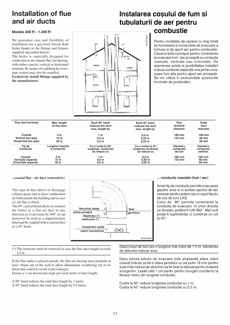
Instalarea co`ului de fum situbulaturii de aer pentru
combustiePentru modelele de cazane cu tiraj for^atse furnizeaz™ si conductele de evacuare afumului si de aport aer pentru combustie.Cazanul este conceput pentru conectareala evacuare fum / aer proasp™t cu conductecoaxiale, verticale sau orizontale. Deasemenea exista si posibilitatea instal™riia doua conducte separate una pentru eva-cuare fum alta pentru aport aer proasp™t.Se vor utiliza in exclusivitate accesoriilefurnizate de produc™tor.
Lungime maximaa conductei
5 m15 m30 m
Cu o curba la 90°lungimea conductei
se reduce cu
1 m0,5 m0,5 m
Cu o curba la 45°lungimea conductei
se reduce cu
0,5 m0,25 m0,25 m
Diametruconductei
de fum
100 mm133 mm
-
Installation of flueand air ductsModels 240 Fi - 1.240 Fi
We guarantee ease and flexibility ofinstallation for a gas-fired forced draftboiler thanks to the fittings and fixturessupplied (described below).The boiler is especially designed forconnection to an exhaust flue / air ducting,with either coaxial, vertical or horizontalterminal. By means of a splitting kit a two-pipe system may also be installed.Exclusively install fittings supplied bythe manufacturer.
Flueterminaldiameter
100 mm133 mm
-
Each 45° bendreduces the ductmax. length by
0,5 m0,25 m0,25 m
Each 90° bendreduces the ductmax. length by
1 m0,5 m0,5 m
Max. lengthof flue duct
5 m15 m30 m
Flue duct terminal
CoaxialVertical two-pipe
Horizontal two-pipe
Outerduct
diameter
100 mm80 mm80 mm
9405030830
... conducte coaxiale (fum / aer)
Acest tip de conducte permite evacuareagazelor arse si in acelasi aportul de aernecesar pentru ardere sau in cazul tipuluide cos de fum LAS.Cotul de 90° permite conectarea laconducta de evacuare in orice direc^iese dore`te, put<nd fi rotit 360°. Mai multpoate fi suplimentar si combinat cu cotla 45°.
Daca cosul de fum are o lungime mai mare de 1.5 m elementulde obturare trebuie scos.
Daca iesirea tubului de evacuare este amplasata afara, tubulcoaxial trebuie sa fie in afara peretelui cu cel putin 18 mm pentrua permite inelului de aluminiu sa fie fixat si etansat pentru evitareascurgerilor. Lasati cate 1 cm panta pentru scurgeri (condens) lafiecare metru din lungime conductei.
Curba la 90° reduce lungimea conductei cu 1 m.Curba la 45° reduce lungimea conductei cu 0,5 m.
...coaxial flue - air duct (concentric)
This type of duct allows to disengageexhaust gases and to draw combustionair both outside the building and in casea LAS flue is fitted.The 90° coaxial bend allows to connectthe boiler to a flue-air duct in anydirection as it can rotate by 360°. It canmoreover be used as a supplementarybend and be coupled with a coaxial ductor a 45° bend.
(*) The restrictor must be removed in case the flue duct length exceeds1,5 m.
If the flue outlet is placed outside, the flue-air ducting must protrude atleast 18mm out of the wall to allow alluminium weathering tile to befitted and sealed to avoid water leakages.Ensure a 1 cm downward slope per each metre of duct length.
A 90° bend reduces the total duct length by 1 metre.A 45° bend reduces the total duct length by 0.5 metre.
clema prindere
obstructor (*)
tuburi concentrice
garnitura
Securing clamp Seal
Restrictor (*)
Concentric outlet
9910
0706
00
12
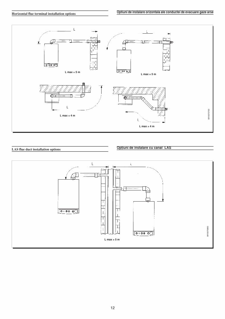
Optiuni de instalare orizontala ale conductei de evacuare gaze arseHorizontal flue terminal installation options
L max = 5 mL max = 5 m
L max = 4 m
L max = 4 m
L max = 5 m
Op^iuni de instalare cu canal LASLAS flue duct installation options
9910
0707
0099
1007
0800
13
L max = 4 m L max = 4 m L max = 3 mL max = 2 m
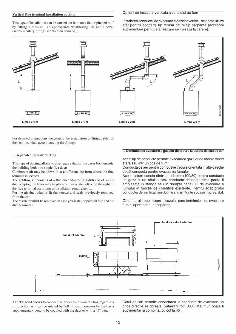
Op^iuni de instalare verticala a canalului de fum
Instalarea conductei de evacuare a gazelor vertical: se poate utilizaat<t pentru acoperi` tip terasa cat si tip `arpanta (accesoriisuplimentare pentru etanseizare se livreaz™ la cerere).
Vertical flue terminal installation options
This type of installation can be carried out both on a flat or pitched roofby fitting a terminal, an appropriate weathering tile and sleeve,(supplementary fittings supplied on demand).
For detailed instructions concerning the installation of fittings refer tothe technical data accompanying the fittings.
… separated flue-air ducting
This type of ducting allows to disengage exhaust flue gases both outsidethe building both into single flue ducts.Comburant air may be drawn in at a different site from where the flueterminal is located.The splitting kit consists of a flue duct adaptor (100/80) and of an airduct adaptor; the latter may be placed either on the left or on the right ofthe flue terminal according to installation requirements.For the air duct adaptor fit the screws and seals previously removedfrom the cap.The restrictor must be removed in case you install separated flue and airduct terminals.
... Conducta de evacuare a gazelor de ardere separata de cea de aer
Acest tip de conducte permite evacuarea gazelor de ardere directafara sau intr-un cos de fum.Conducta de aer pentru combustie trebuie orientata in alte direc^iedec<t conducta pentru evacuarea fumului.Acest sistem consta dintr-un adaptor (100/80) pentru conductade gaze si un altul pentru conducta de aer; ultima poate fiamplasata in st<nga sau in dreapta canalului de evacuare afumului in func^ie de condi^iile existente. Pentru adaptoruluiconductei de aer fixa^i ̀ uruburile si garniturile scoase in prealabil.
Obturatorul trebuie scos in cazul in care terminalele de evacuarefum si aport aer sunt separate.
Intake air duct adaptor
flue duct adaptor
clamp
The 90° bend allows to connect the boiler to flue-air ducting regardlessof direction as it can be rotated by 360°. It can moreover be used as asupplementary bend to be coupled with the duct or with a 45° bend.
Cotul de 90° permite conectarea la conducta de evacuare inorice direc^ie se dore`te, put<nd fi rotit 360°. Mai mult poate fisuplimentar si combinat cu cot la 45°.
9910
0709
0099
1007
1000
14
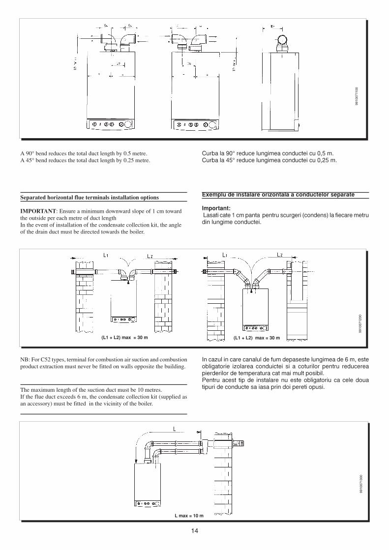
(L1 + L2) max = 30 m (L1 + L2) max = 30 m
Curba la 90° reduce lungimea conductei cu 0,5 m.Curba la 45° reduce lungimea conductei cu 0,25 m.
Exemplu de instalare orizontala a conductelor separate
Important: Lasati cate 1 cm panta pentru scurgeri (condens) la fiecare metrudin lungime conductei.
A 90° bend reduces the total duct length by 0.5 metre.A 45° bend reduces the total duct length by 0.25 metre.
Separated horizontal flue terminals installation options
IMPORTANT: Ensure a minimum downward slope of 1 cm towardthe outside per each metre of duct lengthIn the event of installation of the condensate collection kit, the angleof the drain duct must be directed towards the boiler.
L max = 10 m
NB: For C52 types, terminal for combustion air suction and combustionproduct extraction must never be fitted on walls opposite the building.
The maximum length of the suction duct must be 10 metres.If the flue duct exceeds 6 m, the condensate collection kit (supplied asan accessory) must be fitted in the vicinity of the boiler.
9910
0711
0099
1007
1200
9910
0713
00In cazul in care canalul de fum depaseste lungimea de 6 m, esteobligatorie izolarea conduictei si a coturilor pentru reducereapierderilor de temperatura cat mai mult posibil.Pentru acest tip de instalare nu este obligatoriu ca cele douatipuri de conducte sa iasa prin doi pereti opusi.
15
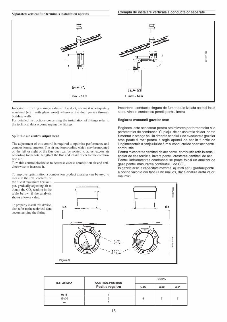
L max = 14 mL max = 15 m
Exemplu de instalare verticala a conductelor separateSeparated vertical flue terminals installation options
Important: if fitting a single exhaust flue duct, ensure it is adequatelyinsulated (e.g.: with glass wool) wherever the duct passes throughbuilding walls.For detailed instructions concerning the installation of fittings refer tothe technical data accompanying the fittings.
Split flue air control adjustment
The adjustment of this control is required to optimise performance andcombustion parameters. The air suction coupling which may be mountedon the left or right of the flue duct can be rotated to adjust excess airaccording to the total length of the flue and intake ducts for the combus-tion air.Turn this control clockwise to decrease excess combustion air and anti-clockwise to increase it.
To improve optimisation a combustion product analyser can be used tomeasure the CO
2 contents of
the flue at maximum heat out-put, gradually adjusting air toobtain the CO
2 reading in the
table below, if the analysisshows a lower value.
To properly install this device,also refer to the technical dataaccompanying the fitting.
Important : conducta singura de fum trebuie izolata aastfel incatsa nu vina in contact cu peretii.pentru instru
Reglarea evacuarii gazelor arse
Reglarea este necesarar pentru otpimizarea performantelor si aparametrilor de combustie. Cuplajul de pe aspiratia de aer poatefi montat in stanga sau in dreapta canalului de evacuare a gazelorarse poate fi rotit pentru a regla aportul de aer in functie delungimea totala a canjalului de fum si conductei de poart aer pentrucombustie.Pentru micsorarea cantitatii de aer pentru combustie rotiti in sensulacelor de ceasornic si invers pentru cresterea cantitatii de aer.Pentru imbunatatirea combustiei se poate folosi un analizor degaze pentru masurarea continutului de CO 2In gazele arse la capacitate maxima, ajustati aerul gradual pentrua obtine valorile din tabelul de mai jos, daca analiza arata valorimai mici.
9910
0714
00
0003
1702
00
Figure 9
sx dx
0004
0601
00
CO2%(L1+L2) MAX CONTROL POSITION
Pozitie regsitru G.20 G.30 G.31
0÷15 115÷30 2 6 7 7
— 3
16
Figura 11
9402
2507
15
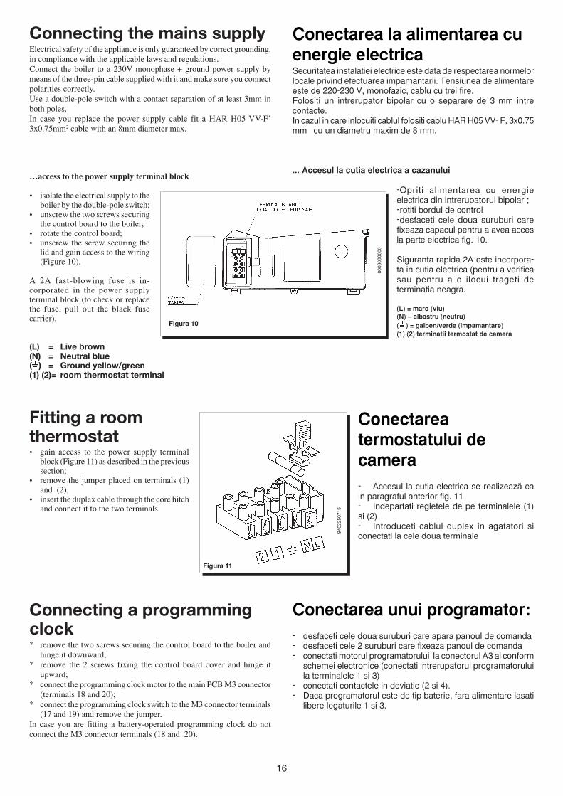
Connecting the mains supplyElectrical safety of the appliance is only guaranteed by correct grounding,in compliance with the applicable laws and regulations.Connect the boiler to a 230V monophase + ground power supply bymeans of the three-pin cable supplied with it and make sure you connectpolarities correctly.Use a double-pole switch with a contact separation of at least 3mm inboth poles.In case you replace the power supply cable fit a HAR H05 VV-F’3x0.75mm2 cable with an 8mm diameter max.
…access to the power supply terminal block
• isolate the electrical supply to theboiler by the double-pole switch;
• unscrew the two screws securingthe control board to the boiler;
• rotate the control board;• unscrew the screw securing the
lid and gain access to the wiring(Figure 10).
A 2A fast-blowing fuse is in-corporated in the power supplyterminal block (to check or replacethe fuse, pull out the black fusecarrier).
(L) = Live brown(N) = Neutral blue( ) = Ground yellow/green(1) (2)= room thermostat terminal
Figura 10
Conectarea la alimentarea cuenergie electricaSecuritatea instalatiei electrice este data de respectarea normelorlocale privind efectuarea impamantarii. Tensiunea de alimentareeste de 220-230 V, monofazic, cablu cu trei fire.Folositi un intrerupator bipolar cu o separare de 3 mm intrecontacte.In cazul in care inlocuiti cablul folositi cablu HAR H05 VV- F, 3x0.75mm cu un diametru maxim de 8 mm.
... Accesul la cutia electrica a cazanului
-Opriti alimentarea cu energieelectrica din intrerupatorul bipolar ;-rotiti bordul de control-desfaceti cele doua suruburi carefixeaza capacul pentru a avea accesla parte electrica fig. 10.
Siguranta rapida 2A este incorpora-ta in cutia electrica (pentru a verificasau pentru a o ilocui trageti determinatia neagra.
(L) = maro (viu)(N) – albastru (neutru)( ) = galben/verde (impamantare)(1) (2) terminatii termostat de camera
0003
0306
00
Conectareatermostatului decamera- Accesul la cutia electrica se realizeaz™ cain paragraful anterior fig. 11- Indepartati regletele de pe terminalele (1)si (2)- Introduceti cablul duplex in agatatori siconectati la cele doua terminale
Conectarea unui programator:- desfaceti cele doua suruburi care apara panoul de comanda- desfaceti cele 2 suruburi care fixeaza panoul de comanda- conectati motorul programatorului la conectorul A3 al conform
schemei electronice (conectati intrerupatorul programatoruluila terminalele 1 si 3)
- conectati contactele in deviatie (2 si 4).- Daca programatorul este de tip baterie, fara alimentare lasati
libere legaturile 1 si 3.
Fitting a roomthermostat• gain access to the power supply terminal
block (Figure 11) as described in the previoussection;
• remove the jumper placed on terminals (1)and (2);
• insert the duplex cable through the core hitchand connect it to the two terminals.
Connecting a programmingclock* remove the two screws securing the control board to the boiler and
hinge it downward;* remove the 2 screws fixing the control board cover and hinge it
upward;* connect the programming clock motor to the main PCB M3 connector
(terminals 18 and 20);* connect the programming clock switch to the M3 connector terminals
(17 and 19) and remove the jumper.In case you are fitting a battery-operated programming clock do notconnect the M3 connector terminals (18 and 20).
17
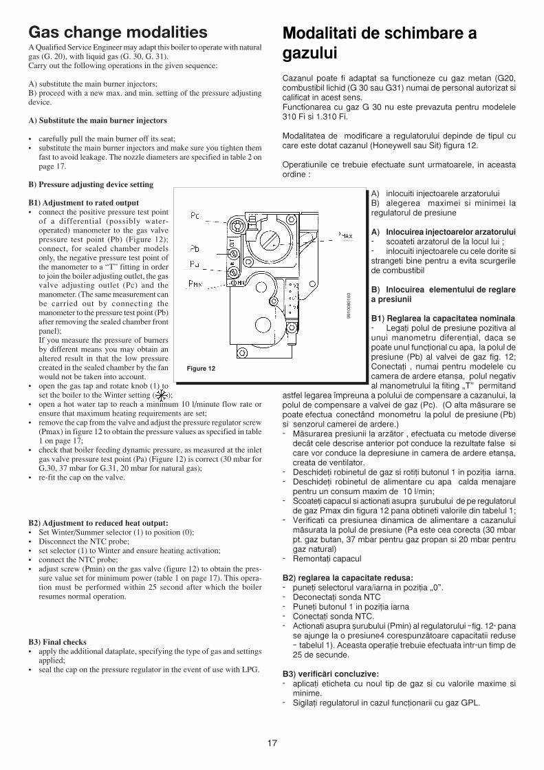
Figure 12
Gas change modalitiesA Qualified Service Engineer may adapt this boiler to operate with naturalgas (G. 20), with liquid gas (G. 30, G. 31).Carry out the following operations in the given sequence:
A) substitute the main burner injectors;B) proceed with a new max. and min. setting of the pressure adjustingdevice.
A) Substitute the main burner injectors
• carefully pull the main burner off its seat;• substitute the main burner injectors and make sure you tighten them
fast to avoid leakage. The nozzle diameters are specified in table 2 onpage 17.
B) Pressure adjusting device setting
B1) Adjustment to rated output• connect the positive pressure test point
of a differential (possibly water-operated) manometer to the gas valvepressure test point (Pb) (Figure 12);connect, for sealed chamber modelsonly, the negative pressure test point ofthe manometer to a “T” fitting in orderto join the boiler adjusting outlet, the gasvalve adjusting outlet (Pc) and themanometer. (The same measurement canbe carried out by connecting themanometer to the pressure test point (Pb)after removing the sealed chamber frontpanel);If you measure the pressure of burnersby different means you may obtain analtered result in that the low pressurecreated in the sealed chamber by the fanwould not be taken into account.
• open the gas tap and rotate knob (1) toset the boiler to the Winter setting ( );
• open a hot water tap to reach a minimum 10 l/minute flow rate orensure that maximum heating requirements are set;
• remove the cap from the valve and adjust the pressure regulator screw(Pmax) in figure 12 to obtain the pressure values as specified in table1 on page 17;
• check that boiler feeding dynamic pressure, as measured at the inletgas valve pressure test point (Pa) (Figure 12) is correct (30 mbar forG.30, 37 mbar for G.31, 20 mbar for natural gas);
• re-fit the cap on the valve.
B2) Adjustment to reduced heat output:• Set Winter/Summer selector (1) to position (0);• Disconnect the NTC probe;• set selector (1) to Winter and ensure heating activation;• connect the NTC probe;• adjust screw (Pmin) on the gas valve (figure 12) to obtain the pres-
sure value set for minimum power (table 1 on page 17). This opera-tion must be performed within 25 second after which the boilerresumes normal operation.
B3) Final checks• apply the additional dataplate, specifying the type of gas and settings
applied;• seal the cap on the pressure regulator in the event of use with LPG.
9910
0801
00
Modalitati de schimbare agazuluiCazanul poate fi adaptat sa functioneze cu gaz metan (G20,combustibil lichid (G 30 sau G31) numai de personal autorizat sicalificat in acest sens.Functionarea cu gaz G 30 nu este prevazuta pentru modelele310 Fi si 1.310 Fi.
Modalitatea de modificare a regulatorului depinde de tipul cucare este dotat cazanul (Honeywell sau Sit) figura 12.
Operatiunile ce trebuie efectuate sunt urmatoarele, in aceastaordine :
A) inlocuiti injectoarele arzatoruluiB) alegerea maximei si minimei laregulatorul de presiune
A) Inlocuirea injectoarelor arzatorului- scoateti arzatorul de la locul lui ;- inlocuiti injectoarele cu cele dorite sistrangeti bine pentru a evita scurgerilede combustibil
B) Inlocuirea elementului de reglarea presiunii
B1) Reglarea la capacitatea nominala- Lega^i polul de presiune pozitiva alunui manometru diferen^ial, daca sepoate unul func^ional cu apa, la polul depresiune (Pb) al valvei de gaz fig. 12;Conecta^i , numai pentru modelele cucamera de ardere etan`a, polul negatival manometrului la fiting „T” permitand
astfel legarea ¶mpreuna a polului de compensare a cazanului, lapolul de compensare a valvei de gaz (Pc). (O alta m™surare sepoate efectua conect<nd monometru la polul de presiune (Pb)si senzorul camerei de ardere.)- M™surarea presiunii la arz™tor , efectuata cu metode diverse
dec<t cele descrise anterior pot conduce la rezultate false sicare vor conduce la depresiune in camera de ardere etan`a,creata de ventilator.
- Deschide^i robinetul de gaz si roti^i butonul 1 in pozi^ia iarna.- Deschide^i robinetul de alimentare cu apa calda menajare
pentru un consum maxim de 10 l/min;- Scoate^i capacul si actionati asupra ̀ urubului de pe regulatorul
de gaz Pmax din figura 12 pana obtineti valorile din tabelul 1;- Verificati ca presiunea dinamica de alimentare a cazanului
m™surata la polul de presiune (Pa este cea corecta (30 mbarpt. gaz butan, 37 mbar pentru gaz propan si 20 mbar pentrugaz natural)
- Remonta^i capacul
B2) reglarea la capacitate redusa:- pune^i selectorul vara/iarna in pozi^ia „0”.- Deconecta^i sonda NTC- Pune^i butonul 1 in pozi^ia iarna- Conecta^i sonda NTC.- Actionati asupra ̀ urubului (Pmin) al regulatorului –fig. 12- pana
se ajunge la o presiune4 corespunz™toare capacitatii reduse– tabelul 1). Aceasta opera^ie trebuie efectuata intr-un timp de25 de secunde.
B3) verific™ri concluzive:- aplica^i eticheta cu noul tip de gaz si cu valorile maxime si
minime.- Sigila^i regulatorul in cazul func^ionarii cu gaz GPL.
18
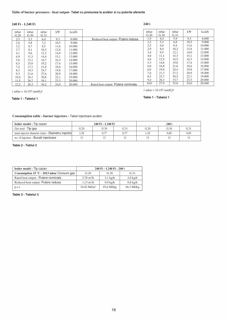
Table of burner pressures - heat output- Tabel cu presiunea la arz™tor si cu puterile aferente
240 Fi - 1.240 Fi
mbar mbar mbar kW kcal/hG.20 G.30 G.312,5 5,3 6,4 9,3 8.000 Reduced heat output- Putere redusa2,8 5,8 7,2 10,5 9.0003,2 6,7 8,5 11,6 10.0003,7 8,1 10,3 12,8 11.0004,1 9,6 12,3 14,0 12.0004,9 11,3 14,4 15,1 13.0005,6 13,1 16,7 16,3 14.0006,5 15,0 19,2 17,4 15.0007,4 17,1 21,8 18,6 16.0008,3 19,3 24,7 19,8 17.0009,3 21,6 27,6 20,9 18.00010,4 24,1 30,8 22,1 19.00011,5 26,7 34,1 23,3 20.00012,2 28,3 36,2 24,0 20.600 Rated heat output- Putere nominala
1 mbar = 10,197 mmH20
Table 1 - Tabelul 1
Consumption table - burner injectors - Tabel injectoare arz™tor
boiler model - Tip cazan 240 Fi - 1.240 Fi 240 i
Gas used - Tip gaz G.20 G.30 G.31 G.20 G.30 G.31
main injector diameter (mm) - Diametru injector 1,28 0,77 0,77 1,18 0,69 0,69
no. of injectors - Bucati injectoare 12 12 12 15 15 15
Table 2 - Teblul 2
240 i
mbar mbar mbar kW kcal/hG.20 G.30 G.311,9 4,4 5,9 9,3 8.0002,2 5,3 6,8 10,5 9.0002,5 6,6 8,4 11,6 10.0002,9 8,0 10,2 12,8 11.0003,4 9,5 12,1 14,0 12.0004,0 11,1 14,3 15,1 13.0004,6 12,9 16,5 16,3 14.0005,3 14,8 19,0 17,4 15.0006,0 16,8 21,6 18,6 16.0006,8 19,0 24,4 19,8 17.0007,6 21,3 27,3 20,9 18.0008,5 23,7 30,5 22,1 19.0009,4 26,3 33,7 23,3 20.000
10,0 27,9 35,8 24,0 20.600
1 mbar = 10,197 mmH20
Table 1 - Tabelul 1
boiler model - Tip cazan 240 Fi - 1.240 Fi - 240 i
Consumption 15 °C - 1013 mbar Consum gaz G.20 G.30 G.31
Rated heat output - Putere nominala 2,78 m3/h 2,1 kg/h 2,0 kg/h
Reduced heat output- Putere redusa 1,13 m3/h 0,9 kg/h 0,8 kg/h
p.c.i. 34,02 MJ/m3 45,6 MJ/kg 46,3 MJ/kg
Table 3 - Tabelul 3
19
Elemente de siguran^a sicontrolCazanele sunt construite pentru a satisface toate prescrip^iileNormativelor Europene aferente, si in particular sunt dotate cu:
- Poten^iometru pentru reglare in timpul func^ionarii de iarna(¶nc™lzire); - Acest dispozitiv define`te temperatura maxima aapei pe circuitul de ¶nc™lzire, temperatura ce are un minim de30º C si o maxima de 85 º C. Pentru cre`terea temperaturii incircuit roti^i butonul 12 in sensul acelor de ceasornic si roti^iinvers pentru mic`orarea temperaturii.
- Poten^iometru pentru reglarea temperaturii apei caldesanitare (1.240 I ) – acest dispozitiv define`te temperaturamaxima a apei calde sanitare. Temperatura minima 35º C si omaxima de 65 º C. Pentru cre`terea temperaturii in circuit roti^ibutonul 13 in sensul acelor de ceasornic si roti^i invers pentrumic`orarea temperaturii.
- Presostat pentru modelul cu tiraj natural.- Acest dispozitivpermite aprinderea arz™torului numai in cazul in care sistemulde evacuare a fumului este in perfecta stare de func^ionare.Daca una din anomaliile de mai jos exista atunci centrala varamane in stand by:- Canalul de fum este obturat- Sistemul de ventila^ie este obturat- Ventilatorul este blocat- Conexiunea dintre canalul de aer de dup™ ventilator sipresostat este ¶ntrerupta (semnalizatorul 4).
- Termostat de fum pentru modelul 240 i Acest dispozitiv, alc™rui senzor este pozi^ionat in partea st<nga a convectoruluide fum, ¶ntrerupe debitul de gaz la arz™tor in cazul in carecanalul de fum este obturat sau lipse`te tirajul. In aceste condi^iicentrala va ramane blocata si numai dup™ ¶ndep™rtarea cauzeide obturare si ap™sarea butonului de resetare 1 este posibilarepetarea aprinderii arz™torului
- Termostat de siguran^a – acest dispozitiv, al c™rui senzor estepozi^ionat deasupra circuitului de ¶nc™lzire, ¶ntrerupe debitulde gaz la arz™tor in cazul supra¶nc™lzirii apei in circuitul primar.In aceste condi^ii centrala va fi blocata si numai dup™¶ndep™rtarea cauzei si resetarea prin rotirea butonului 1 inpozi^ia ( ) .
- Detector al flacarii ionizate- electrodul de detectare a fl™c™rii,amplasat in partea sting™ a arz™torului, garanteaz™ operareain siguran^a in cazul in care nu exista flac™ra sau arz™torul nuse aprinde complet. In aceste condi^ii sistemul se va bloca. Enecesara rotirea butonului (1) in pozi^ia ( ) .
- Presostat diferen^ial hidraulic - - acest dispozitiv, montat pesistemul hidraulic, permite aprinderea arz™torului numai dacapompa indeplineste condi^iile de pornire, si totodat™ acestsistem protejeaz™ pompa de eventuale scurgeri dinschimb™torul apa – fum sau blocaje. Se roteste butonul 1 inpozi^ia ( ) .
- Valva de siguran^a hidraulica (circuitul de ¶nc™lzire) – acestdispozitiv, setat la 3 bar, deserve`te sistemul de ¶nc™lzire cen-trala. Se recomanda conectarea acestui dispozitiv la un sistemde drenaj. Este absolut interzisa folosirea acestui dispozitivpentru golirea totala a instala^iei.
Este interzisa dezactivarea ORIC¨RUI sistem de siguran^a.
Recomandam conectarea valvei relief de presiune la un punctde drenaj. Este absolut interzis ca acest punct de drenaj sa fieutilizat pentru golirea instala^iei de ¶nc™lzire.
Control and operationdevicesThe boiler has been designed in full compliance with European referencestandards and in particular is equipped with the following:
• Central heating temperature adjustment potentiometerThis potentiometer sets the central heating flow max. temperature.Its temperature range goes from 30 °C min. to 85 °C max.To increase the temperature turn knob (5) clockwise and anticlockwiseto decrease it.
• Domestic hot water temperature adjusting potentiometer (not fiitedon model 1.240 Fi)This potentiometer sets the domestic hot water max. temperature. Itstemperature range goes from 35 °C min. to 65 °C max according tothe water inlet flow rate.To increase the temperature turn knob (6) clockwise and anticlockwiseto decrease it.
• Air pressure switch for models 240 Fi and 1.240 FiThis switch allows the main burner to switch on provided the exhaustflue duct efficiency is perfect.In the event of one of the following faults:• the flue terminal is obstructed• the venturi is obstructed• the fan is blocked• the connection between the venturi and the air pressure switch is
not activethe boiler will stay on stand-by.
• Flue thermostat for model 240 iThis device has a sensor positioned on the left section of the flueextraction hood and shuts off the gas flow to the main burner if theflue duct is obstructed or in the event of draught failure.Under such conditions the boiler is blocked and relighting (by meansof button in Figure 6 page 7) will only be possible after the cause ofthe anomaly has been removed.
• Overheat thermostatThanks to a sensor placed on the heating flow, this thermostatinterrupts the gas flow to the main burner in case the water containedin the primary system has overheated. Under such conditions the boileris blocked and relighting (by means of button in Figure 5 page 7) willonly be possible after the cause of the anomaly has been removed.
It is forbidden to disenable this safety device
• Flame ionization detectorThe flame sensing electrode, placed on the right of the burner,guarantees safety of operation in case of gas failure or incompleteinterlighting of the main burner.Under such conditions the boiler is blocked.Rotate selector (1) briefly to position ( ) to restore normal operatingconditions.
• Hydraulic differential pressure sensorThis pressure sensor, fitted on the hydraulic assembly, allows themain burner to light provided the pump head is as required and protectsthe flue-water exchanger from possible lacks of water or blockingsof the pump.
• Hydraulic safety valve (heating circuit)This device is set to 3 bar and is used for the heating circuit.
The safety valve should be connected to a siphoned drain. Use a a meansof draining the heating circuit is strictly prohibited.
20
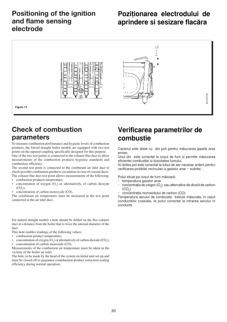
Pozi^ionarea electrodului deaprindere si sesizare flac™ra
Figure 13
Positioning of the ignitionand flame sensingelectrode
Check of combustionparametersTo measure combustion performance and hygiene levels of combustionproducts, the forced draught boiler models are equipped with two testpoints on the tapered coupling specifically designed for this purpose.One of the two test points is connected to the exhaust flue duct to allowmeasurements of the combustion products hygienic standards andcombustion efficiency.The second test point is connected to the comburant air inlet duct tocheck possible combustion products circulation in case of coaxial ducts.The exhaust flue duct test point allows measurements of the following:• combustion products temperature;• concentration of oxygen (O
2) or, alternatively, of carbon dioxyde
(CO2);
• concentration of carbon monoxyde (CO).The comburant air temperature must be measured at the test pointconnected to the air inlet duct.
For natural draught models a hole should be drilled on the flue exhaustduct at a distance from the boiler that is twice the internal diameter of theduct.This hole enables readings of the following values:• combustion product temperature;• concentration of oxygen (O
2) or alternatively of carbon dioxide (CO
2);
• concentration of carbon monoxide (CO).Measurements of the combustion air temperature must be taken in thevicinity of the boiler air inlet.The hole, to be made by the head of the system on initial unit set-up andmust be closed off to guarantee comnbustion product extraction sealingefficiency during normal operation.
9912
0701
00
Verificarea parametrilor decombustieCazanul este dotat cu doi poli pentru m™surarea gazele arseemise.Unul din este conectat la co`ul de fum si permite m™surareaeficientei combustiei si toxicitatea fumului.Al doilea pol este conectat la tubul de aer necesar arderii pentruverificarea posibilei recirculari a gazelor arse – sc<ntei .
Polul situat pe co`ul de fum m™soar™:- temperatura gazelor arse- concentra^ia de oxigen (O2), sau alternative de dioxid de carbon
(CO2)- concentra^ia monoxidului de carbon (CO)Temperatura aerului de combustie trebuie m™surata, in cazulconductelor coaxiale, la polul conectat la intrarea aerului inconducta.
21
OUTPUT l/h -
Graph 1 - Graficul 1
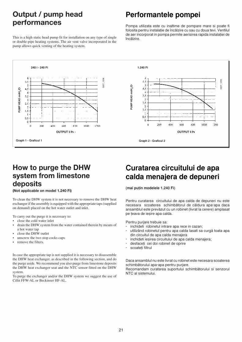
Performantele pompeiPompa utilizata este cu inaltime de pompare mare si poate fifolosita pentru instala^ie de ¶nc™lzire cu sau cu doua tevi. Ventilulde aer incorporat in pompa permite aerisirea rapida instala^iei de¶nc™lzire.
PU
MP
HE
AD
mH
2O
Output / pump headperformances
This is a high static head pump fit for installation on any type of singleor double-pipe heating systems. The air vent valve incorporated in thepump allows quick venting of the heating system.
Curatarea circuitului de apacalda menajera de depuneri(mai pu^in modelele 1.240 Fi)
Pentru curatarea circuitului de apa calda de depuneri nu estenecesara scoaterea schimb™torul de c™ldura apa-apa dacaansamblul este prev™zut cu un robinet (livrat la cerere) amplasatpe ^eava de ie`ire apa calda.
Pentru purjare trebuie sa:- inchideti robinetul intrare apa rece in cazan;- utiliz<nd robinetul pentru apa calda lasati sa curg™ toata apa
din circuitul de apa calda menajera- inchideti ie`irea circuitului de apa calda menajera;- desface^i cei doi robinet de oprire- scoate^i filtrul
Daca ansamblul nu este livrat cu robinet este necesara scoatereaschimb™torului apa-apa pentru purjare.Recomandam curatarea suportului schimb™torului si senzorulNTC al sistemului.
How to purge the DHWsystem from limestonedeposits(Not applicable on model 1.240 Fi)
To clean the DHW system it is not necessary to remove the DHW heatexchanger if the assembly is equipped with the appropriate taps (suppliedon demand) placed on the hot water outlet and inlet.
To carry out the purge it is necessary to:• close the cold water inlet• drain the DHW system from the water contained therein by means of
a hot water tap• close the DHW outlet• unscrew the two stop cocks caps• remove the filters.
In case the appropriate tap is not supplied it is necessary to disassemblethe DHW heat exchanger, as described in the following section, and dothe purge aside. We recommend you also purge from limestone depositsthe DHW heat exchanger seat and the NTC sensor fitted on the DHWsystem.To purge the exchanger and/or the DHW system we suggest the use ofCillit FFW-AL or Beckinser HF-AL.
PU
MP
HE
AD
mH
2O
OUTPUT l/h
Graph 2 - Graficul 2
240 i - 240 Fi 1.240 Fi
0207
_120
5
0207
_120
6
22
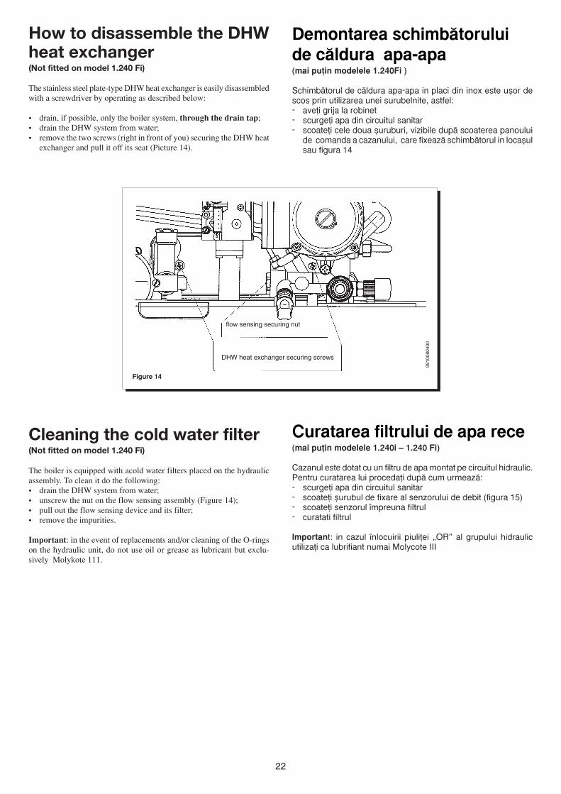
Figure 14
DHW heat exchanger securing screws
flow sensing securing nut
9910
0804
00
How to disassemble the DHWheat exchanger(Not fitted on model 1.240 Fi)
The stainless steel plate-type DHW heat exchanger is easily disassembledwith a screwdriver by operating as described below:
• drain, if possible, only the boiler system, through the drain tap;• drain the DHW system from water;• remove the two screws (right in front of you) securing the DHW heat
exchanger and pull it off its seat (Picture 14).
Demontarea schimb™toruluide c™ldura apa-apa(mai pu^in modelele 1.240Fi )
Schimb™torul de c™ldura apa-apa in placi din inox este u`or descos prin utilizarea unei surubelnite, astfel:- ave^i grija la robinet- scurge^i apa din circuitul sanitar- scoate^i cele doua `uruburi, vizibile dup™ scoaterea panoului
de comanda a cazanului, care fixeaz™ schimb™torul in loca`ulsau figura 14
Curatarea filtrului de apa rece(mai pu^in modelele 1.240i – 1.240 Fi)
Cazanul este dotat cu un filtru de apa montat pe circuitul hidraulic.Pentru curatarea lui proceda^i dup™ cum urmeaz™:- scurge^i apa din circuitul sanitar- scoate^i `urubul de fixare al senzorului de debit (figura 15)- scoate^i senzorul ¶mpreuna filtrul- curatati filtrul
Important: in cazul ¶nlocuirii piuli^ei „OR” al grupului hidraulicutiliza^i ca lubrifiant numai Molycote III
Cleaning the cold water filter(Not fitted on model 1.240 Fi)
The boiler is equipped with acold water filters placed on the hydraulicassembly. To clean it do the following:• drain the DHW system from water;• unscrew the nut on the flow sensing assembly (Figure 14);• pull out the flow sensing device and its filter;• remove the impurities.
Important: in the event of replacements and/or cleaning of the O-ringson the hydraulic unit, do not use oil or grease as lubricant but exclu-sively Molykote 111.
23
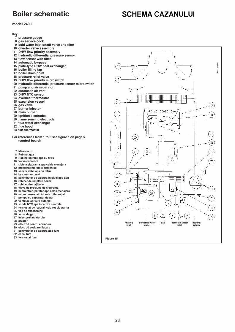
SCHEMA CAZANULUIBoiler schematicmodel 240 i
9910
0806
00
Key:7 pressure gauge8 gas service cock9 cold water inlet on/off valve and filter
10 diverter valve assembly11 DHW flow priority assembly12 hydraulic differential pressure sensor13 flow sensor with filter14 automatic by-pass15 plate-type DHW heat exchanger16 boiler filling tap17 boiler drain point18 pressure relief valve19 DHW flow priority microswitch20 hydraulic differential pressure sensor microswitch21 pump and air separator22 automatic air vent23 DHW NTC sensor24 overheat thermostat25 expansion vessel26 gas valve27 burner injector28 main burner29 ignition electrodes30 flame sensing electrode31 flue-water exchanger32 flue hood33 flue thermostat
For references from 1 to 6 see figure 1 on page 5(control board)
7 Manometru8 Robinet gaz9 Robinet intrare apa cu filtru
10 Valva cu trei cai11 sistem siguran^a apa calda menajera12 presostat hidraulic diferen^ial13 senzor debit apa cu filtru14 by-pass automat15 schimbator de c™ldura in placi apa-apa16 robinet de umplere boiler17 robinet drenaj boiler18 vlava de presiune de siguran^a19 microintrerupatator apa calda menajera20 micro presostat hidraulic diferen^ial21 pompa cu separator de aer22 ventil de aerisire automat23 sonda NTC apa incalzire centrala24 termostat de (supraincalzire) siguran^a25 vas de expansiune26 valva de gaz27 injectorul arzatorului28 arzator29 electrod pentru aprindere30 electrod sesizare flacara31 schimbator de caldura apa-fum32 canal fum33 termostat fum Figure 15
heating domestic water gas domestic water heatinginlet outlet inlet return
24
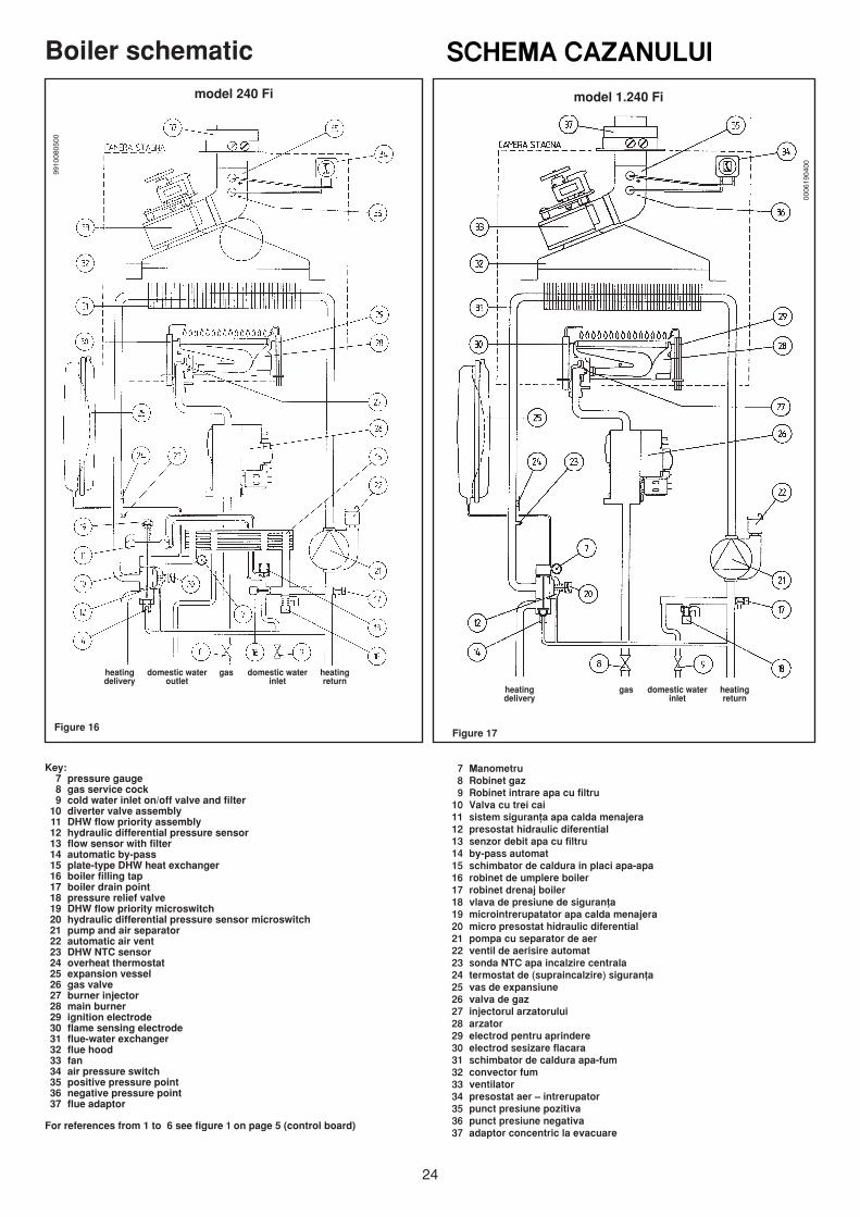
SCHEMA CAZANULUIBoiler schematicmodel 240 Fi model 1.240 Fi
9910
0805
00
0006
1904
00
Key:7 pressure gauge8 gas service cock9 cold water inlet on/off valve and filter
10 diverter valve assembly11 DHW flow priority assembly12 hydraulic differential pressure sensor13 flow sensor with filter14 automatic by-pass15 plate-type DHW heat exchanger16 boiler filling tap17 boiler drain point18 pressure relief valve19 DHW flow priority microswitch20 hydraulic differential pressure sensor microswitch21 pump and air separator22 automatic air vent23 DHW NTC sensor24 overheat thermostat25 expansion vessel26 gas valve27 burner injector28 main burner29 ignition electrode30 flame sensing electrode31 flue-water exchanger32 flue hood33 fan34 air pressure switch35 positive pressure point36 negative pressure point37 flue adaptor
For references from 1 to 6 see figure 1 on page 5 (control board)
Figure 16Figure 17
7 Manometru8 Robinet gaz9 Robinet intrare apa cu filtru
10 Valva cu trei cai11 sistem siguran^a apa calda menajera12 presostat hidraulic diferential13 senzor debit apa cu filtru14 by-pass automat15 schimbator de caldura in placi apa-apa16 robinet de umplere boiler17 robinet drenaj boiler18 vlava de presiune de siguran^a19 microintrerupatator apa calda menajera20 micro presostat hidraulic diferential21 pompa cu separator de aer22 ventil de aerisire automat23 sonda NTC apa incalzire centrala24 termostat de (supraincalzire) siguran^a25 vas de expansiune26 valva de gaz27 injectorul arzatorului28 arzator29 electrod pentru aprindere30 electrod sesizare flacara31 schimbator de caldura apa-fum32 convector fum33 ventilator34 presostat aer – intrerupator35 punct presiune pozitiva36 punct presiune negativa37 adaptor concentric la evacuare
heating domestic water gas domestic water heatingdelivery outlet inlet return
heating gas domestic water heatingdelivery inlet return
25
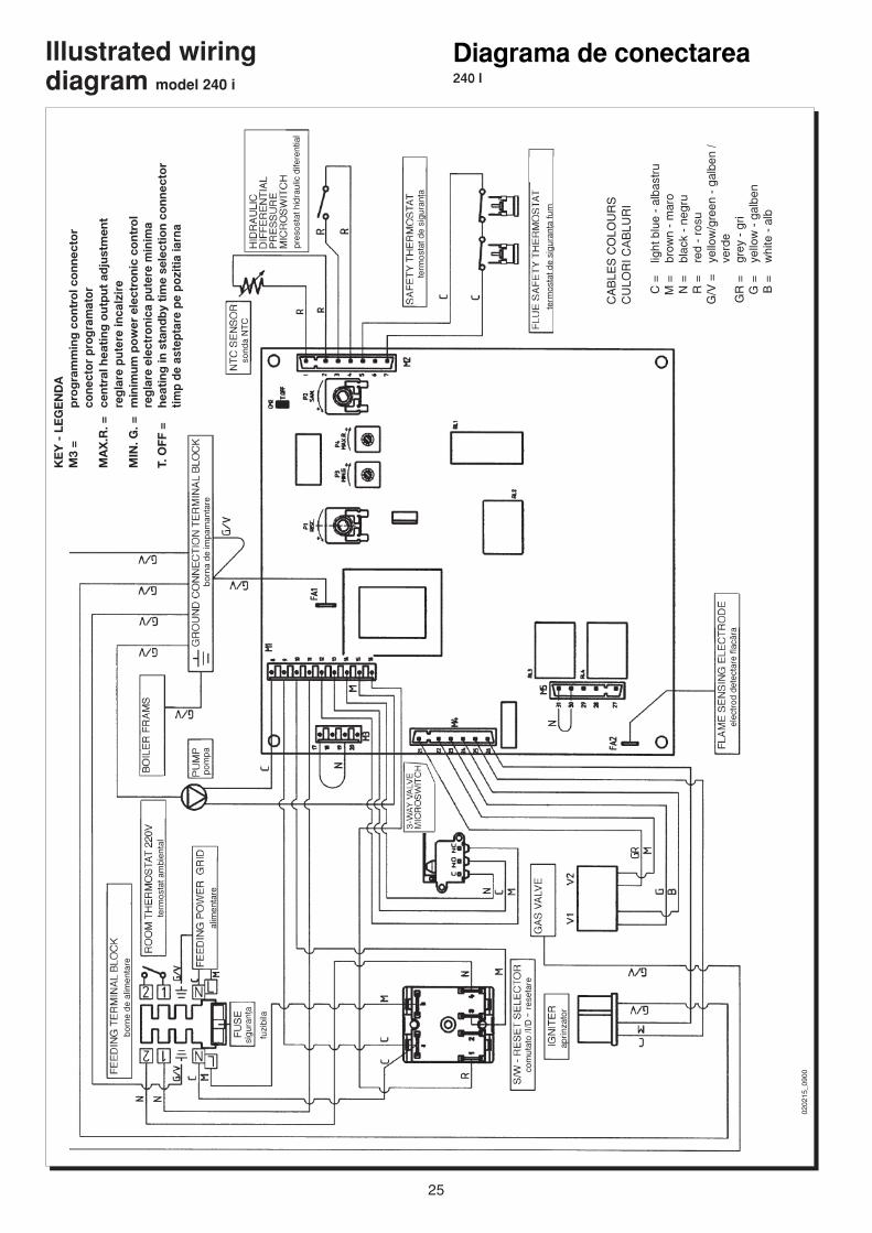
Diagrama de conectarea240 I
Illustrated wiringdiagram model 240 i
0202
15_0
900
KE
Y -
LE
GE
ND
AM
3 =
pro
gra
mm
ing
co
ntro
l co
nnec
tor
cone
ctor
pro
gram
ator
MA
X.R
. =ce
ntra
l hea
ting
out
put
ad
just
men
tre
glar
e pu
tere
inca
lzir
eM
IN. G
. =m
inim
um p
ow
er e
lect
roni
c co
ntro
lre
glar
e el
ectr
onic
a pu
tere
min
ima
T. O
FF =
heat
ing
in s
tand
by
tim
e se
lect
ion
conn
ecto
rtim
p de
ast
epta
re p
e po
zitia
iarn
a
CA
BLE
S C
OLO
UR
SC
ULO
RI C
AB
LUR
I
C =
light
blu
e -
alba
stru
M =
brow
n -
mar
oN
=bl
ack
- ne
gru
R =
red
- ro
suG
/V =
yello
w/g
reen
- g
albe
n /
verd
eG
R =
grey
- g
riG
=ye
llow
- g
albe
nB
=w
hite
- a
lb
elec
trod
det
ecta
re fl
ac™r
a
born
e de
alim
enta
re
term
osta
t de
sigu
ran^
a
pres
osta
t hid
raul
ic d
ifere
ntia
l
sond
a N
TC
com
utat
o /I/
D –
res
etar
e
born
a de
impa
man
tare
alim
enta
re
sigu
ran^
a
fuzi
bila
pom
pa
term
osta
t am
bien
tal
aprin
zato
r
term
osta
t de
sigu
ran^
a fu
m
26
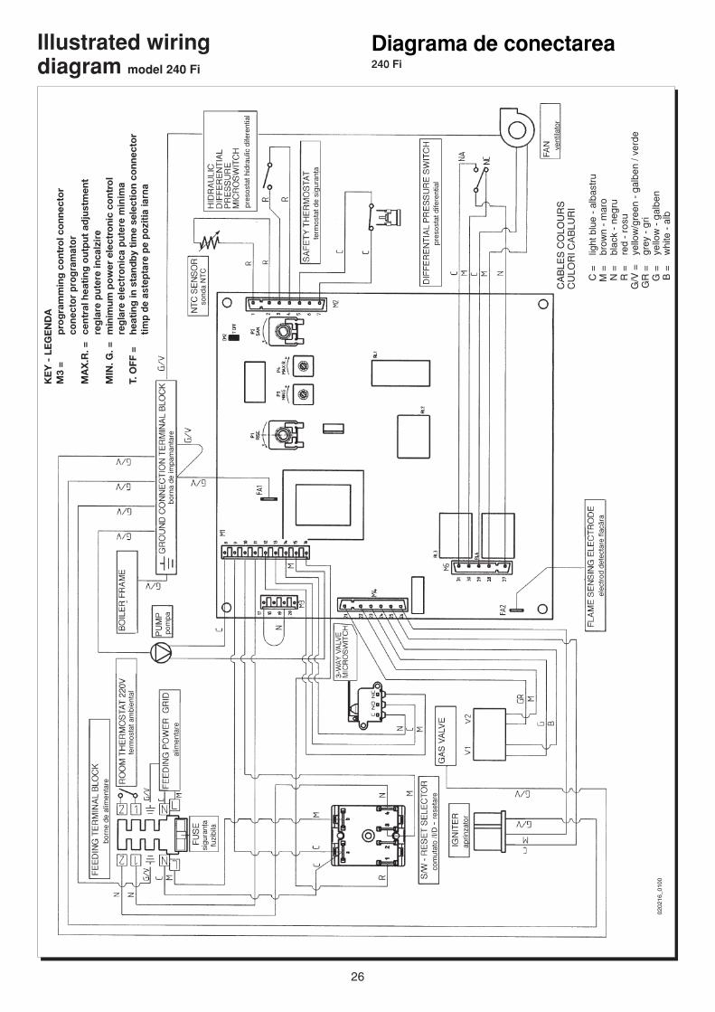
Illustrated wiringdiagram model 240 Fi
Diagrama de conectarea240 Fi
0202
16_0
100
CA
BLE
S C
OLO
UR
SC
ULO
RI C
AB
LUR
I
C =
light
blu
e -
alba
stru
M =
brow
n -
mar
oN
=bl
ack
- ne
gru
R =
red
- ro
suG
/V =
yello
w/g
reen
- g
albe
n / v
erde
GR
=gr
ey -
gri
G =
yello
w -
gal
ben
B =
whi
te -
alb
elec
trod
det
ecta
re fl
ac™r
a
born
e de
alim
enta
re
term
osta
t de
sigu
ran^
a
pres
osta
t hid
raul
ic d
ifere
ntia
l
sond
a N
TC
com
utat
o /I/
D –
res
etar
e
born
a de
impa
man
tare
alim
enta
re
sigu
ran^
afu
zibi
la
pom
pa
term
osta
t am
bien
tal
KE
Y -
LE
GE
ND
AM
3 =
pro
gra
mm
ing
co
ntro
l co
nnec
tor
cone
ctor
pro
gram
ator
MA
X.R
. =ce
ntra
l hea
ting
out
put
ad
just
men
tre
glar
e pu
tere
inca
lzir
eM
IN. G
. =m
inim
um p
ow
er e
lect
roni
c co
ntro
lre
glar
e el
ectr
onic
a pu
tere
min
ima
T. O
FF =
heat
ing
in s
tand
by
tim
e se
lect
ion
conn
ecto
rtim
p de
ast
epta
re p
e po
zitia
iarn
a
vent
ilato
r
pres
osta
t dife
rent
ial
aprin
zato
r
27
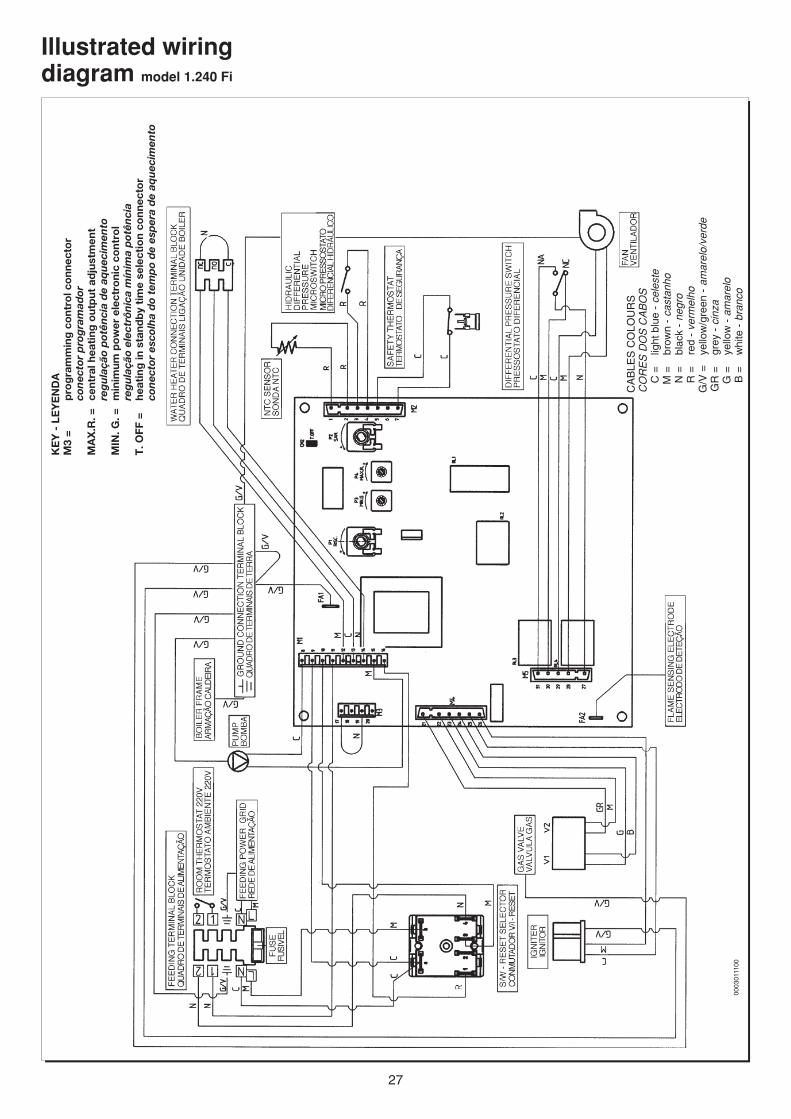
Illustrated wiringdiagram model 1.240 Fi
0003
0111
00
KE
Y -
LE
YE
ND
AM
3 =
pro
gra
mm
ing
co
ntro
l co
nnec
tor
con
ecto
r p
rog
ram
ador
MA
X.R
. =ce
ntra
l hea
ting
out
put
ad
just
men
tre
gu
laçã
o p
otên
cia
de
aqu
ecim
ento
MIN
. G. =
min
imum
po
wer
ele
ctro
nic
cont
rol
reg
ula
ção
elec
trôn
ica
mín
ima
pot
ênci
aT
. OFF
=he
atin
g in
sta
ndb
y ti
me
sele
ctio
n co
nnec
tor
con
ecto
r es
colh
a d
o te
mp
o d
e es
per
a d
e aq
uec
imen
to
CA
BLE
S C
OLO
UR
SC
OR
ES
DO
S C
AB
OS
C =
light
blu
e -
cele
ste
M =
brow
n -
cast
anho
N =
blac
k -
negr
oR
=re
d -
verm
elho
G/V
=ye
llow
/gre
en -
am
arel
o/ve
rde
GR
=gr
ey -
cin
zaG
=ye
llow
- a
mar
elo
B =
whi
te -
bra
nco
28
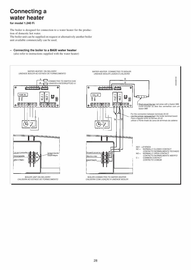
Connecting awater heaterfor model 1.240 Fi
The boiler is designed for connection to a water heater for the produc-tion of domestic hot water.The boiler unit can be supplied on request or alternatively another boilerunit available commercially can be used.
– Connecting the boiler to a BAXI water heater(also refer to instructions supplied with the water heater)
0003
2801
00
WATER HEATER ON DELIVERYUNIDADE BOILER AO ESTADO DE FORNECIMENTO
WATER HEATER CONNECTED TO BOILERUNIDADE BOILER LIGADA À CALDEIRA
For the connection between terminals 20-22use the jumper removed from the boiler terminal boardPara a ligação entre os bornes 20-22utilizar o Ponte tirado da caixa de terminais da caldeira
KEY - LEYENDANC = NORMALLY CLOSED CONTACT
CONTACTO NORMALMENTE FECHADONO = NORMALLY OPEN CONTACT
CONTACTO NORMALMENTE ABERTOC = COMMON CONTACT
CONTACTO COMUM
BOILER UNIT ON DELIVERYCALDEIRA AO ESTADO DE FORNECIMENTO
BOILER CONNECTED TO WATER HEATERCALDEIRA COM LIGAÇÃO À UNIDADE BOILER
Short circuit the two red wires with a faston MMCurto-circuitar os dois fios vermelhos com umfaston MM
CONNECTED TO SWITCH S/WLIGADOS A INTERRUPTOR V/I
29
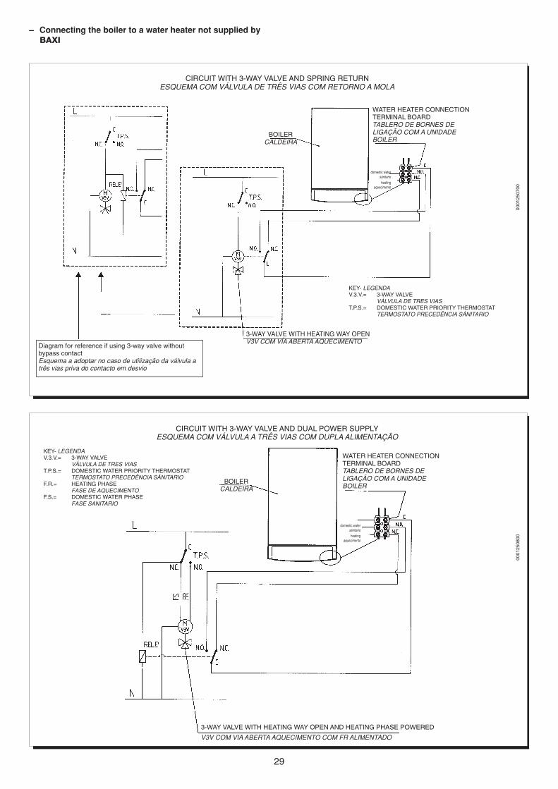
– Connecting the boiler to a water heater not supplied byBAXI
0001
2507
00
KEY- LEGENDAV.3.V.= 3-WAY VALVE
VÁLVULA DE TRES VIAST.P.S.= DOMESTIC WATER PRIORITY THERMOSTAT
TERMOSTATO PRECEDÊNCIA SÁNITARIO
BOILERCALDEIRA
WATER HEATER CONNECTIONTERMINAL BOARDTABLERO DE BORNES DELIGAÇÃO COM A UNIDADEBOILER
domestic watersánitario
heatingaquecimento
3-WAY VALVE WITH HEATING WAY OPENV3V COM VÍA ABERTA AQUECIMENTO
CIRCUIT WITH 3-WAY VALVE AND SPRING RETURNESQUEMA COM VÁLVULA DE TRÊS VIAS COM RETORNO A MOLA
Diagram for reference if using 3-way valve withoutbypass contactEsquema a adoptar no caso de utilização da válvula atrês vias priva do contacto em desvio
0001
2508
00
KEY- LEGENDAV.3.V.= 3-WAY VALVE
VÁLVULA DE TRES VIAST.P.S.= DOMESTIC WATER PRIORITY THERMOSTAT
TERMOSTATO PRECEDÊNCIA SÁNITARIOF.R.= HEATING PHASE
FASE DE AQUECIMENTOF.S.= DOMESTIC WATER PHASE
FASE SANITARIO
BOILERCALDEIRA
WATER HEATER CONNECTIONTERMINAL BOARDTABLERO DE BORNES DELIGAÇÃO COM A UNIDADEBOILER
domestic watersánitario
heatingaquecimento
3-WAY VALVE WITH HEATING WAY OPEN AND HEATING PHASE POWERED
V3V COM VIA ABERTA AQUECIMENTO COM FR ALIMENTADO
CIRCUIT WITH 3-WAY VALVE AND DUAL POWER SUPPLYESQUEMA COM VÁLVULA A TRÊS VIAS COM DUPLA ALIMENTAÇÃO
30
NORMATIVEPunerea in functiune a instalatiei
E interzisa instalarea unor instalatii de gaz cu densitatea relati-va mai mare de 0,80 in localuri cu pardoseala sub planul campiei.Nu e admisa punerea in operare a tuburilor de gaz in contact cuconductele de apa.Este intezisa interventia in regulatoarele integrate aparatului, incalibrarea injectoarelor si a arzatorului principal, modificareaformei sau dimensiunilor oricarei piese care are influenta asuprarandamentului termic al aparatului.Daca contorul este situat in exteriorul locuin^ei e necesarainserarea unui robinet analog in interiorul locuin^ei.Recipientele cu gaz LPG trebuie asezate astfel incat asupra lorsa nu actioneze direct surse de caldura capabile sa le aduca la otemperaturi mai mari de 500C. Fiecare local in care se gasesteun recipient cu gaz LPG trebuie sa fie aerisit prin ferestre, usisau alte deschideri in exterior.In orice local destinat locuirii, cu suprafata de pana la 20 m3, nutrebuie tinut mai mult de un recipient pentru gaz, cu un continutde 15 kg. In locale cu suprafata de pana la 50 m2 nu trebuieinstalate mai mult de 2 recipiente cu un continut complementarde 30 kg. Instalarea recipientelor cu un con^inut global superior a50 kg trebuie f™cuta in exterior.
Cazane cu tiraj for^atDistantele minime pentru sec^iunile de eflux in atmosfera suntindicate in prospectul urm™tor:
Pozi^ia terminalului distanta aparateintre 16-35 kW
MmSub fereastra A 600Sub deschiderea aerisirii B 600Sub strea`ina C 300Sub balcon D 300De la o fereastra adiacenta E 400De la o deschidere a unei aerisiri Adiacente F 600De la tuburile de descarcare G 300De la un colt al edificiului H 300De la o intrare a edificiului I 300De la sol L 2500Intre 2 terminale in verticala M 1500Intre 2 terminale in orizontala N 1000De la o suprafata frontalaFara deschideri si terminale,intr-o raza de 3 m de la gura deie`ire a aburilor O 2000Idem, dar cu deschideri si terminale P 3000
Ventilarea spatiilor pentru aparatele de tip BE indispensabil ca in localurile in care sunt instalate aparate pegaz sa poata exista un flux de aer necesar pentru reglareacombustiei.Afluxul de aer trebuie sa vina pe o cale directa prin;- deschideri permanente care dau in exterior- conducte de ventilare, simple sau colective, ramificate.Deschiderile pe peretii externi ai localului care trebuie ventilattrebuie sa corespunda urmatoarelor cerinte:- sa existe o sectiune libera de trecere de cel putin 6 cmpatrati pentru fiecare kW de putere termica instalata cu un minimde 100 cm patrati.- Sa fie protejate cu zabrele, plase metalice astfel incat sanu fie redusa sectiunea utila indicata mai sus- Sa fie realizate in asa fel incat gurile deschiderii, atat ininterior cat si in exterior, sa nu poata fi obstructionate.

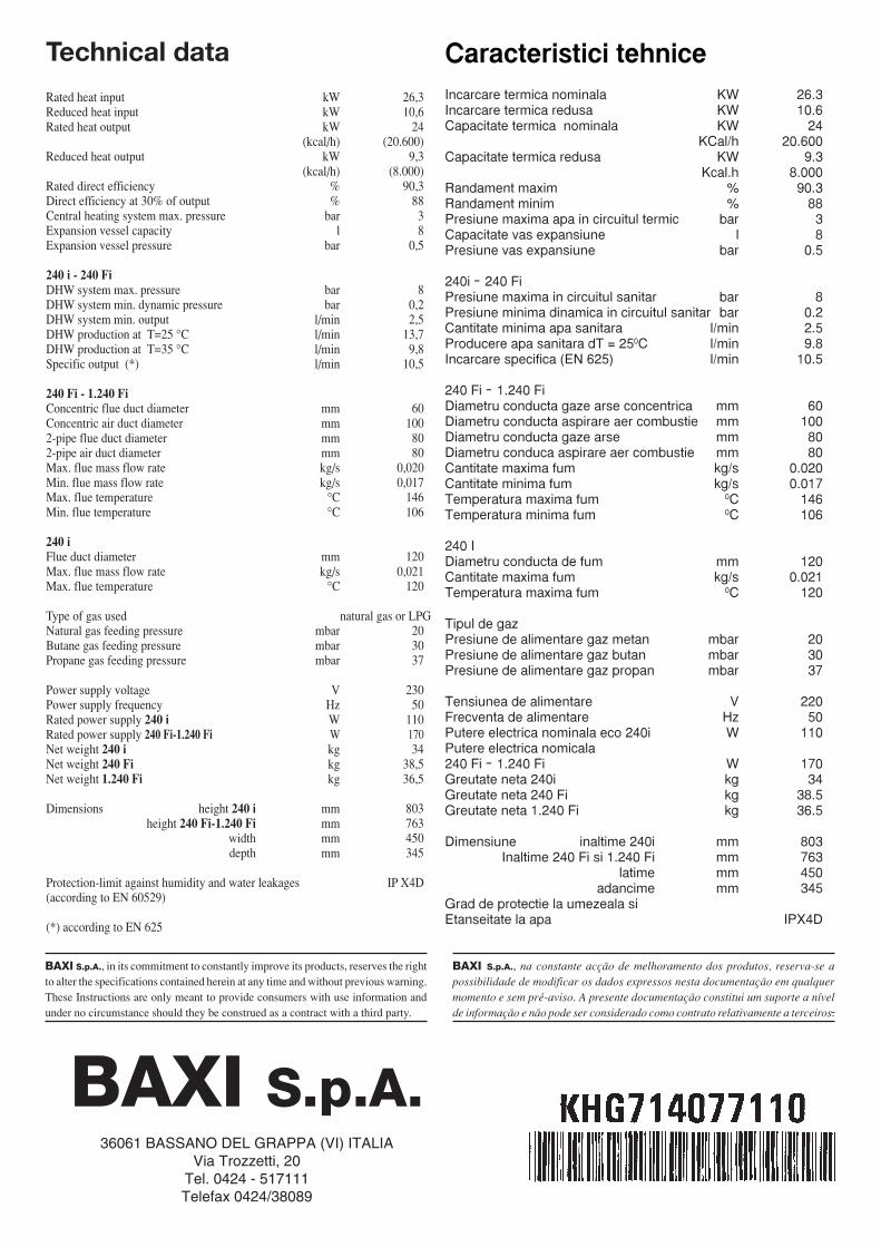
Caracteristici tehniceIncarcare termica nominala KW 26.3Incarcare termica redusa KW 10.6Capacitate termica nominala KW 24
KCal/h 20.600Capacitate termica redusa KW 9.3
Kcal.h 8.000Randament maxim % 90.3Randament minim % 88Presiune maxima apa in circuitul termic bar 3Capacitate vas expansiune l 8Presiune vas expansiune bar 0.5
240i – 240 FiPresiune maxima in circuitul sanitar bar 8Presiune minima dinamica in circuitul sanitar bar 0.2Cantitate minima apa sanitara l/min 2.5Producere apa sanitara dT = 250C l/min 9.8Incarcare specifica (EN 625) l/min 10.5
240 Fi – 1.240 FiDiametru conducta gaze arse concentrica mm 60Diametru conducta aspirare aer combustie mm 100Diametru conducta gaze arse mm 80Diametru conduca aspirare aer combustie mm 80Cantitate maxima fum kg/s 0.020Cantitate minima fum kg/s 0.017Temperatura maxima fum 0C 146Temperatura minima fum 0C 106
240 IDiametru conducta de fum mm 120Cantitate maxima fum kg/s 0.021Temperatura maxima fum 0C 120
Tipul de gazPresiune de alimentare gaz metan mbar 20Presiune de alimentare gaz butan mbar 30Presiune de alimentare gaz propan mbar 37
Tensiunea de alimentare V 220Frecventa de alimentare Hz 50Putere electrica nominala eco 240i W 110Putere electrica nomicala240 Fi – 1.240 Fi W 170Greutate neta 240i kg 34Greutate neta 240 Fi kg 38.5Greutate neta 1.240 Fi kg 36.5
Dimensiune inaltime 240i mm 803Inaltime 240 Fi si 1.240 Fi mm 763
latime mm 450 adancime mm 345
Grad de protectie la umezeala siEtanseitate la apa IPX4D
Technical data
Rated heat input kW 26,3Reduced heat input kW 10,6Rated heat output kW 24
(kcal/h) (20.600)Reduced heat output kW 9,3
(kcal/h) (8.000)Rated direct efficiency % 90,3Direct efficiency at 30% of output % 88Central heating system max. pressure bar 3Expansion vessel capacity l 8Expansion vessel pressure bar 0,5
240 i - 240 FiDHW system max. pressure bar 8DHW system min. dynamic pressure bar 0,2DHW system min. output l/min 2,5DHW production at T=25 °C l/min 13,7DHW production at T=35 °C l/min 9,8Specific output (*) l/min 10,5
240 Fi - 1.240 FiConcentric flue duct diameter mm 60Concentric air duct diameter mm 1002-pipe flue duct diameter mm 802-pipe air duct diameter mm 80Max. flue mass flow rate kg/s 0,020Min. flue mass flow rate kg/s 0,017Max. flue temperature °C 146Min. flue temperature °C 106
240 iFlue duct diameter mm 120Max. flue mass flow rate kg/s 0,021Max. flue temperature °C 120
Type of gas used natural gas or LPGNatural gas feeding pressure mbar 20Butane gas feeding pressure mbar 30Propane gas feeding pressure mbar 37
Power supply voltage V 230Power supply frequency Hz 50Rated power supply 240 i W 110Rated power supply 240 Fi-1.240 Fi W 170Net weight 240 i kg 34Net weight 240 Fi kg 38,5Net weight 1.240 Fi kg 36,5
Dimensions height 240 i mm 803height 240 Fi-1.240 Fi mm 763
width mm 450depth mm 345
Protection-limit against humidity and water leakages IP X4D(according to EN 60529)
(*) according to EN 625
BAXI S.p.A., na constante acção de melhoramento dos produtos, reserva-se apossibilidade de modificar os dados expressos nesta documentação em qualquermomento e sem pré-aviso. A presente documentação constitui um suporte a nívelde informação e não pode ser considerado como contrato relativamente a terceiros.
BAXI S.p.A., in its commitment to constantly improve its products, reserves the rightto alter the specifications contained herein at any time and without previous warning.These Instructions are only meant to provide consumers with use information andunder no circumstance should they be construed as a contract with a third party.
BAXI S.p.A.36061 BASSANO DEL GRAPPA (VI) ITALIA
Via Trozzetti, 20Tel. 0424 - 517111Telefax 0424/38089