Embed Size (px)
Citation preview
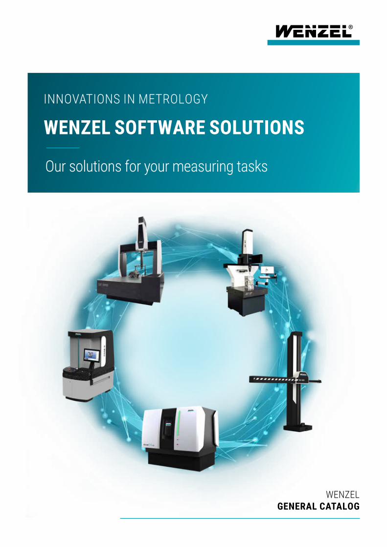
Our solutions for your measuring tasks
INNOVATIONS IN METROLOGY
WENZEL SOFTWARE SOLUTIONS
WENZEL GENERAL CATALOG
2
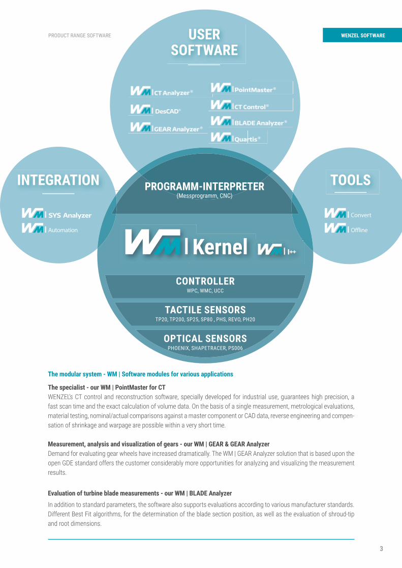
WENZEL Software PRODUCT RANGE SOFTWARE
The fundamental idea is that we can offer software solu-tions from WENZEL for all machines and applications that offer the same operating strategies but cover specialist functional scopes. The importance of software in machine engineering has also increased dramatically over the last few years. We recognized this many years ago and with the takeover of Metromec AG in Switzerland, we have es-tablished an in-house development center for our core software. At the Swiss site and other sites, around 50 em-ployees are working on our solutions that are installed at several thousand workstations. It is not just the importance of software that is continually changing, so too are the type and intensity of use. Depending on the choice of machine, we offer the ideal software solution from our portfolio for every machine. However, customers now combine differ-ent measuring tasks on different machines, they also want toothed gears or turbine blades on classic coordinate mea-suring machines or they switch between tactile probes and optical sensors. The WENZEL software architecture is designed for this multiple and redundant integration into different solutions. Based on a common HW abstraction layer, the different ap-plication solutions build up (see figure).
• The basics – WM | Kernel• The all-rounder – WM | Quartis• The skyscraper – WM | PointMaster• The construction kit – WM | Software Module
The WENZEL SW family follows a similar concept as Mi-crosoft. There are good reasons for the parallel existence of word processing, spreadsheet, e-mail and presentation software. However, similar interface concepts make it easier to familiarize oneself with and switch between solu-tions. This is exactly WENZEL’s claim! The best possible solution for each application - from WENZEL and from a proven uniform concept.
WENZEL METROLOGYSOFTWARE SOLUTIONS The basics – our WM | Kernel
The WM | Kernel is delivered in the background with all our solutions. The drivers to connect the probes and sensors as well as the different machine types are plugged into it. Via the I++ interfaces, numerous third-party products can also be integrated into the WENZEL landscape.
The all-rounder – our WM | QuartisThe new version of our flagship – WM | Quartis is presented in detail in this edition of the General cat-alogue. Even at first glance, it is clear that there is a significant difference. The interface now follows the new Group-wide style guide and has a fresh, modern design.
The skyscraper – our WM | PointMasterOur WM | PointMaster is distinguished by its process-ing of large data volumes of point clouds, polymesh-es and voxels as well as a high degree of application flexibility. In 2018, the new interface solution was implemented along with a number of additional func-tions. PointMaster offers a wide range of modules that enable the user to process point clouds, model polymeshes, perform reverse engineering and create CAD models. Furthermore, WM | PointMaster forms the basis for our special solutions in computed topography and styling.
Automated measurement & evaluation – our WM | Generator
The WM | Generator is used to automatically gener-ate measuring programs from measuring plans. The newest development at WENZEL, for customers who want to reduce the effort for generating measuring programs.
Transparency for operation and control – our WM | SYS Analyzer
The WM | SYS Analyzer offers all information around the operation and use of the installed WENZEL mea-surement solutions at a glance.
3
PRODUCT RANGE SOFTWARE WENZEL SOFTWARE
Automation O�ine
Convert
The modular system - WM | Software modules for various applications
The specialist - our WM | PointMaster for CTWENZEL’s CT control and reconstruction software, specially developed for industrial use, guarantees high precision, a fast scan time and the exact calculation of volume data. On the basis of a single measurement, metrological evaluations, material testing, nominal/actual comparisons against a master component or CAD data, reverse engineering and compen-sation of shrinkage and warpage are possible within a very short time.
Measurement, analysis and visualization of gears - our WM | GEAR & GEAR AnalyzerDemand for evaluating gear wheels have increased dramatically. The WM | GEAR Analyzer solution that is based upon the open GDE standard offers the customer considerably more opportunities for analyzing and visualizing the measurement results.
Evaluation of turbine blade measurements - our WM | BLADE Analyzer
In addition to standard parameters, the software also supports evaluations according to various manufacturer standards. Different Best Fit algorithms, for the determination of the blade section position, as well as the evaluation of shroud-tip and root dimensions.
CONTROLLER
TACTILE SENSORS
OPTICAL SENSORS
WPC, WMC, UCC
TP20, TP200, SP25, SP80 , PHS, REVO, PH20
PHOENIX, SHAPETRACER, PS006
4
WM | Quartis PRODUCT RANGE SOFTWARE
FEATURES
P Geometry, freeform and curves combined in one measuring software
P Supports manual and CNC measuring devices of various types
P Scanning with tactile and optical sensors and 5-axis measuring heads
P Form and position evaluation according to the latest ISO GPS and ASME standards
P DMIS 5.2 Standard complements the intuitive Quartis programming language
P Structured data management in relational database (MS Access / SQL-Server)
P Report generator for descriptive measurement reports
P Operator-friendly operation with quick selection panel, 1-click program start
P Ready for special applications thanks to numerous interfaces and add-ons
WM | QuartisAUTOMATED MEASUREMENT & EVALUATION
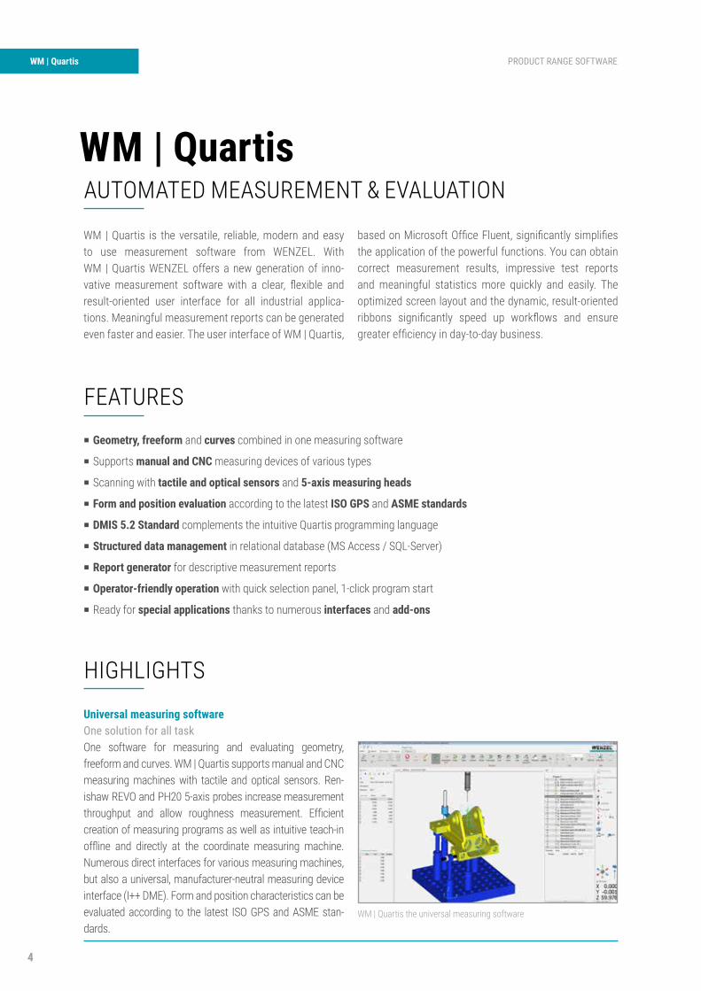
WM | Quartis is the versatile, reliable, modern and easy to use measurement software from WENZEL. With WM | Quartis WENZEL offers a new generation of inno-vative measurement software with a clear, flexible and result-oriented user interface for all industrial applica-tions. Meaningful measurement reports can be generated even faster and easier. The user interface of WM | Quartis,
based on Microsoft Office Fluent, significantly simplifies the application of the powerful functions. You can obtain correct measurement results, impressive test reports and meaningful statistics more quickly and easily. The optimized screen layout and the dynamic, result-oriented ribbons significantly speed up workflows and ensure greater efficiency in day-to-day business.
HIGHLIGHTS
Universal measuring softwareOne solution for all taskOne software for measuring and evaluating geometry, freeform and curves. WM | Quartis supports manual and CNC measuring machines with tactile and optical sensors. Ren-ishaw REVO and PH20 5-axis probes increase measurement throughput and allow roughness measurement. Efficient creation of measuring programs as well as intuitive teach-in offline and directly at the coordinate measuring machine. Numerous direct interfaces for various measuring machines, but also a universal, manufacturer-neutral measuring device interface (I++ DME). Form and position characteristics can be evaluated according to the latest ISO GPS and ASME stan-dards.
WM | Quartis the universal measuring software
5
PRODUCT RANGE SOFTWARE WM | Quartis
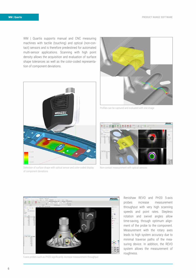
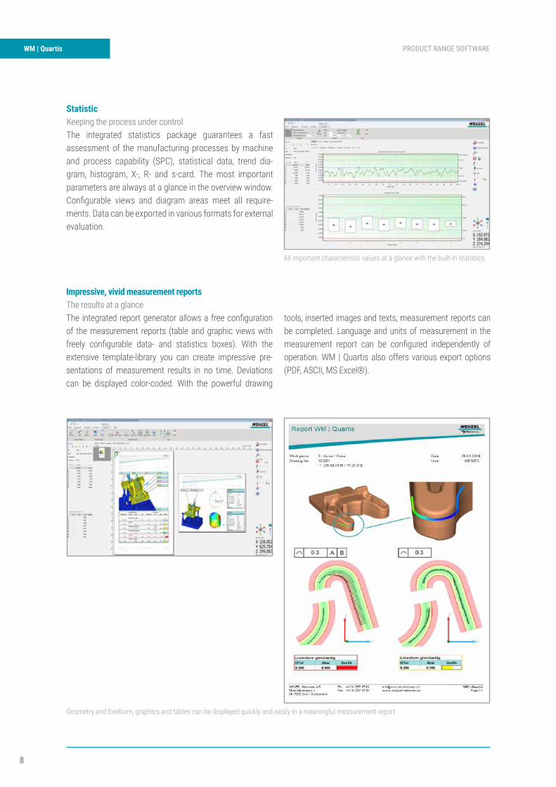
MeasurementsComplete tasks smartly, efficiently and quicklyWM | Quartis measures geometric components, freeform and curves. With the proven Click ‘n’ Measure™ functionality, a dynamic measurement strategy library and numerous sophis-ticated tools, measuring tasks are quick and easy. The basis for measuring is the centrally arranged, large working window with the 3D graphics. The live preview shows the active mea-surement strategy and guides the user more quickly to the correct settings. Measurements can be made by single point acquisition, scanning and self-centering. Safety levels and collision checking prevent damage to the measuring device. With powerful alignment functions and a world-class best-fit, all alignment tasks can be performed easily. Standardized fil-ters and outlier removal eliminate disturbances on the material surface.
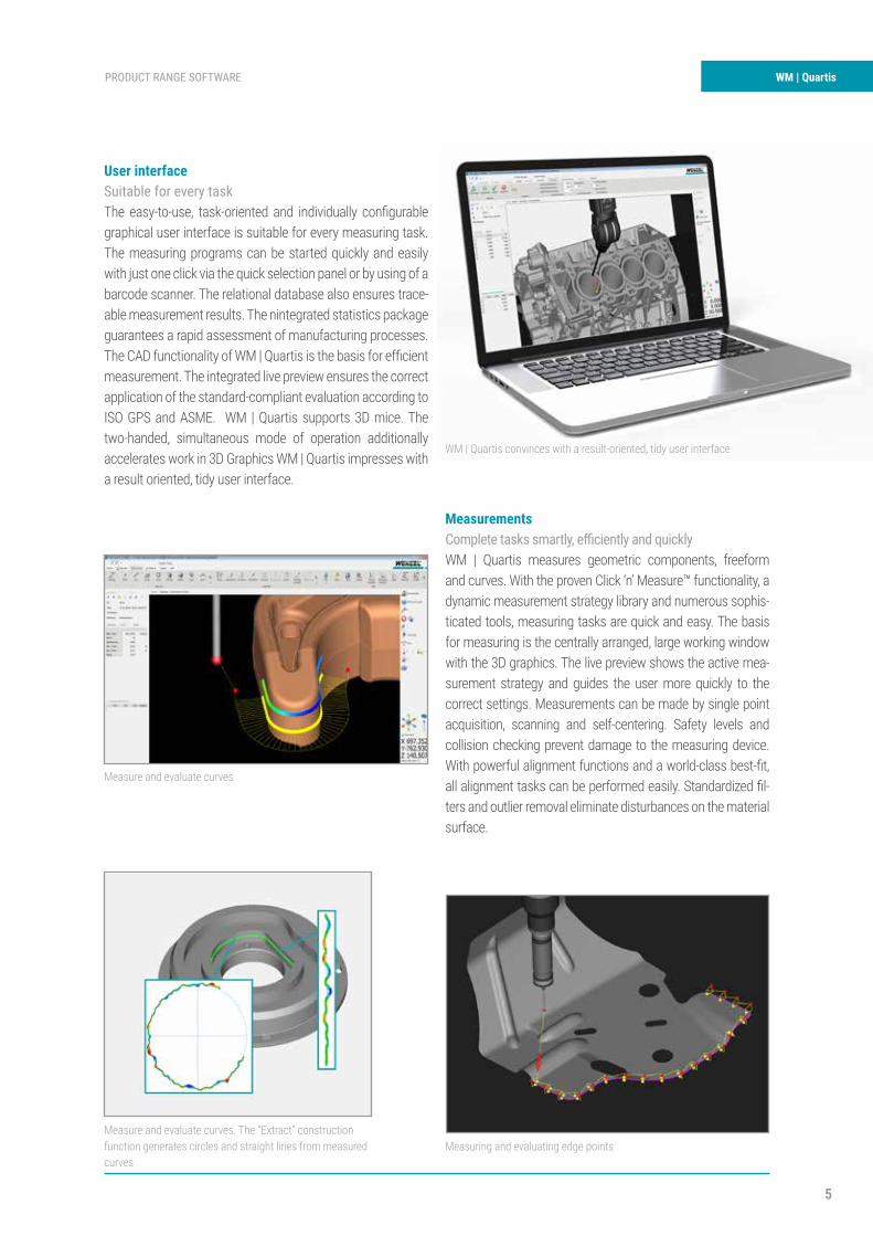
User interfaceSuitable for every taskThe easy-to-use, task-oriented and individually configurable graphical user interface is suitable for every measuring task. The measuring programs can be started quickly and easily with just one click via the quick selection panel or by using of a barcode scanner. The relational database also ensures trace-able measurement results. The nintegrated statistics package guarantees a rapid assessment of manufacturing processes. The CAD functionality of WM | Quartis is the basis for efficient measurement. The integrated live preview ensures the correct application of the standard-compliant evaluation according to ISO GPS and ASME. WM | Quartis supports 3D mice. The two-handed, simultaneous mode of operation additionally accelerates work in 3D Graphics WM | Quartis impresses with a result oriented, tidy user interface.
WM | Quartis convinces with a result-oriented, tidy user interface
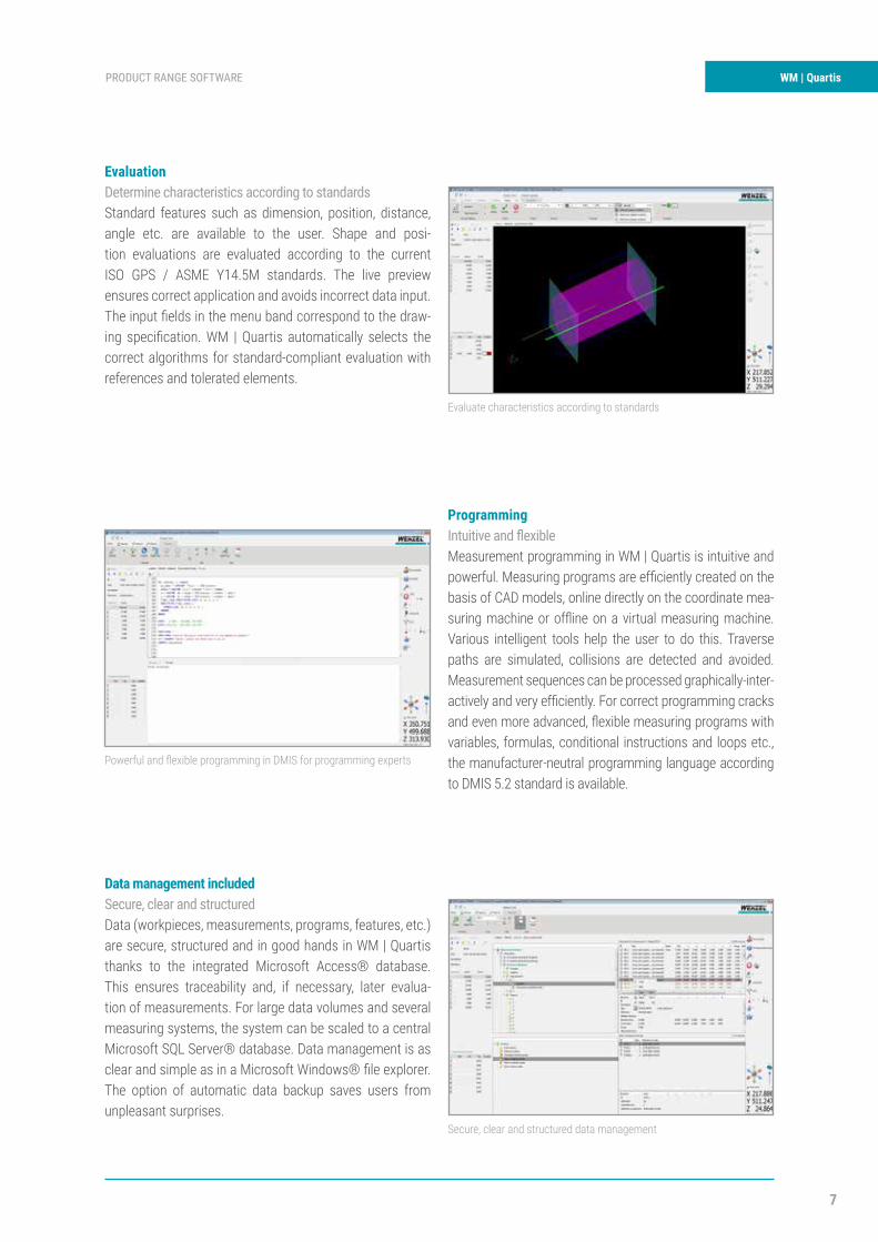
Measure and evaluate curves
Measuring and evaluating edge pointsMeasure and evaluate curves. The “Extract” construction function generates circles and straight lines from measured curves
6
WM | Quartis PRODUCT RANGE SOFTWARE
WM | Quartis supports manual and CNC measuring machines with tactile (touching) and optical (non-con-tact) sensors and is therefore predestined for automated multi-sensor applications. Scanning with high point density allows the acquisition and evaluation of surface shape tolerances as well as the color-coded representa-tion of component deviations.
Renishaw REVO and PH20 5-axis probes increase measurement throughput with very high scanning speeds and point rates. Stepless rotation and swivel angles allow time-saving, through optimum align-ment of the probe to the component. Measurement with the rotary axes leads to high system accuracy due to minimal traverse paths of the mea-suring device. In addition, the REVO system allows the measurement of roughness.
Detection of surface shape with optical sensor and color-coded display of component deviations
Profiles can be captured and evaluated with one image
Non-contact measurement with optical sensors
5-axis probes such as PH20 significantly increase measurement throughput
7
PRODUCT RANGE SOFTWARE WM | Quartis
EvaluationDetermine characteristics according to standardsStandard features such as dimension, position, distance, angle etc. are available to the user. Shape and posi-tion evaluations are evaluated according to the current ISO GPS / ASME Y14.5M standards. The live preview ensures correct application and avoids incorrect data input. The input fields in the menu band correspond to the draw-ing specification. WM | Quartis automatically selects the correct algorithms for standard-compliant evaluation with references and tolerated elements.
Data management includedSecure, clear and structuredData (workpieces, measurements, programs, features, etc.) are secure, structured and in good hands in WM | Quartis thanks to the integrated Microsoft Access® database. This ensures traceability and, if necessary, later evalua-tion of measurements. For large data volumes and several measuring systems, the system can be scaled to a central Microsoft SQL Server® database. Data management is as clear and simple as in a Microsoft Windows® file explorer. The option of automatic data backup saves users from unpleasant surprises.
ProgrammingIntuitive and flexibleMeasurement programming in WM | Quartis is intuitive and powerful. Measuring programs are efficiently created on the basis of CAD models, online directly on the coordinate mea-suring machine or offline on a virtual measuring machine. Various intelligent tools help the user to do this. Traverse paths are simulated, collisions are detected and avoided. Measurement sequences can be processed graphically-inter-actively and very efficiently. For correct programming cracks and even more advanced, flexible measuring programs with variables, formulas, conditional instructions and loops etc., the manufacturer-neutral programming language according to DMIS 5.2 standard is available.
Evaluate characteristics according to standards
Secure, clear and structured data management
Powerful and flexible programming in DMIS for programming experts
8
WM | Quartis PRODUCT RANGE SOFTWARE
StatisticKeeping the process under controlThe integrated statistics package guarantees a fast assessment of the manufacturing processes by machine and process capability (SPC), statistical data, trend dia-gram, histogram, X-, R- and s-card. The most important parameters are always at a glance in the overview window. Configurable views and diagram areas meet all require-ments. Data can be exported in various formats for external evaluation.
Impressive, vivid measurement reportsThe results at a glanceThe integrated report generator allows a free configuration of the measurement reports (table and graphic views with freely configurable data- and statistics boxes). With the extensive template-library you can create impressive pre-sentations of measurement results in no time. Deviations can be displayed color-coded. With the powerful drawing
tools, inserted images and texts, measurement reports can be completed. Language and units of measurement in the measurement report can be configured independently of operation. WM | Quartis also offers various export options (PDF, ASCII, MS Excel®).
All important characteristic values at a glance with the built-in statistics
Geometry and freeform, graphics and tables can be displayed quickly and easily in a meaningful measurement report
PRODUCT RANGE SOFTWARE WM | Quartis
Special applicationsGet the most out of your measurement software
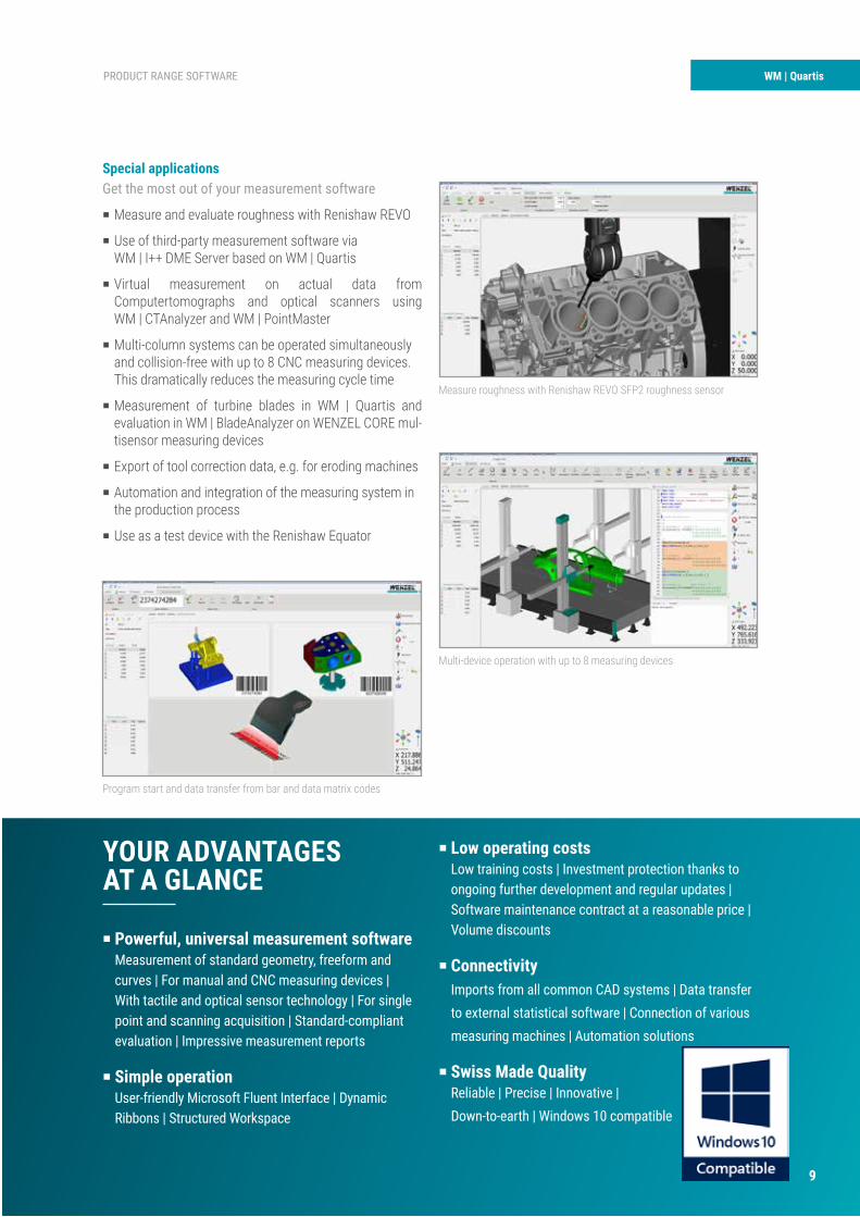
P Measure and evaluate roughness with Renishaw REVO
P Use of third-party measurement software via WM | I++ DME Server based on WM | Quartis
P Virtual measurement on actual data from Computertomographs and optical scanners using
WM | CTAnalyzer and WM | PointMaster
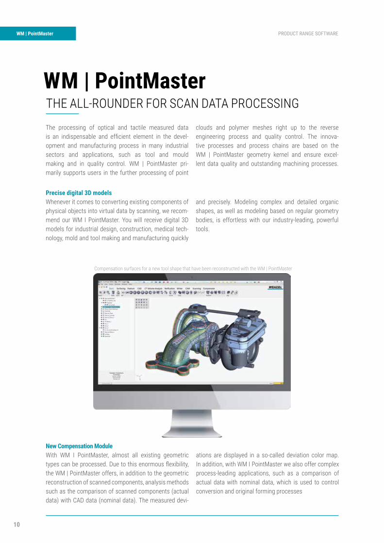
P Multi-column systems can be operated simultaneously and collision-free with up to 8 CNC measuring devices. This dramatically reduces the measuring cycle time
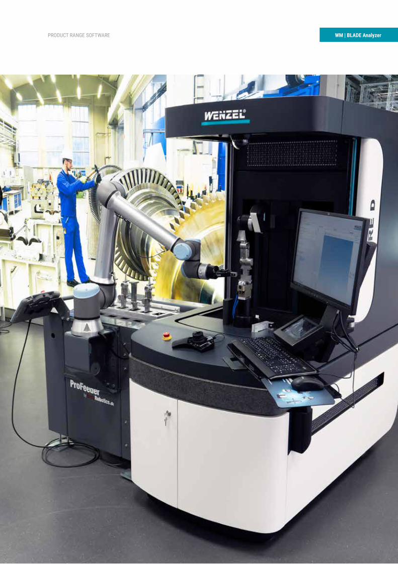
P Measurement of turbine blades in WM | Quartis and evaluation in WM | BladeAnalyzer on WENZEL CORE mul- tisensor measuring devices
P Export of tool correction data, e.g. for eroding machines
P Automation and integration of the measuring system in the production process
P Use as a test device with the Renishaw Equator
Measure roughness with Renishaw REVO SFP2 roughness sensor
Multi-device operation with up to 8 measuring devices
Program start and data transfer from bar and data matrix codes
P Powerful, universal measurement softwareMeasurement of standard geometry, freeform and curves | For manual and CNC measuring devices | With tactile and optical sensor technology | For single point and scanning acquisition | Standard-compliant evaluation | Impressive measurement reports
P Simple operation User-friendly Microsoft Fluent Interface | Dynamic Ribbons | Structured Workspace
YOUR ADVANTAGES AT A GLANCE
P Low operating costsLow training costs | Investment protection thanks to ongoing further development and regular updates | Software maintenance contract at a reasonable price | Volume discounts
P ConnectivityImports from all common CAD systems | Data transfer to external statistical software | Connection of various measuring machines | Automation solutions
P Swiss Made QualityReliable | Precise | Innovative | Down-to-earth | Windows 10 compatible
9
10
WM | PointMaster PRODUCT RANGE SOFTWARE
Precise digital 3D models Whenever it comes to converting existing components of physical objects into virtual data by scanning, we recom-mend our WM I PointMaster. You will receive digital 3D models for industrial design, construction, medical tech-nology, mold and tool making and manufacturing quickly
and precisely. Modeling complex and detailed organic shapes, as well as modeling based on regular geometry bodies, is effortless with our industry-leading, powerful tools.
WM | PointMasterTHE ALL-ROUNDER FOR SCAN DATA PROCESSING
The processing of optical and tactile measured data is an indispensable and efficient element in the devel-opment and manufacturing process in many industrial sectors and applications, such as tool and mould making and in quality control. WM | PointMaster pri-marily supports users in the further processing of point
clouds and polymer meshes right up to the reverse engineering process and quality control. The innova-tive processes and process chains are based on the WM | PointMaster geometry kernel and ensure excel-lent data quality and outstanding machining processes.
New Compensation ModuleWith WM I PointMaster, almost all existing geometric types can be processed. Due to this enormous flexibility, the WM | PointMaster offers, in addition to the geometric reconstruction of scanned components, analysis methods such as the comparison of scanned components (actual data) with CAD data (nominal data). The measured devi-
ations are displayed in a so-called deviation color map. In addition, with WM I PointMaster we also offer complex process-leading applications, such as a comparison of actual data with nominal data, which is used to control conversion and original forming processes
Compensation surfaces for a new tool shape that have been reconstructed with the WM | PointMaster
11
PRODUCT RANGE SOFTWARE WM | PointMaster
CADcasting
Casting moldCAD creation
CADmold
Selectivelaser sintering
Sandmold
Measurement:nominal/actual
comparison
CAD–
Sand mold<
Tolerance
Yes
Correctionmanufacturing
parametersNo
CastingRawcasting
Measurement:nominal/actual
comparison
CAD–
Casting<
Tolerance
CastingOK
Manufacturing parameters
Distortion compensation
Geometry
No
Yes
Alignment of actual- to nominal component Compensation strategy
represented by sections
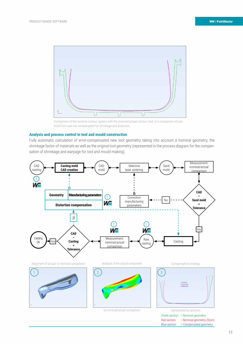
Analysis and process control in tool and mould constructionFully automatic calculation of error-compensated new tool geometry taking into account a nominal geometry, the shrinkage factor of materials as well as the original tool geometry (represented in the process diagram for the compen-sation of shrinkage and warpage for tool and mould making).
1
1 ...1 ...
1 ...2
3
2 3
Comparison of the nominal contour (green) with the scanned actual contour (red) of a component whose mold form was not compensated for shrinkage and distortion
Analysis of the actual component
by nominal/actual comparison Green sectionRed sectionBlue section
= Nominal geometry = Nominal geometry (Scan)= Compensated geometry
12
WM | PointMaster PRODUCT RANGE SOFTWARE
P Shrinkage and distortion correctionFor tool and die makers | Sophisticated functions andalgorithms | Compensation of the formed or originalcomponents
P Comprehensive format supportHandling scan and CT data | Support of all commonscan, CAD, CT and CNC formats
P Extensive functionsCreation of documents including presentation toolsfor measurement reports, documentation | Reports fororder preparation | Freely available viewer
P Support of numerous data typesPoint clouds, polylines, polymasks | Surfaces and curvesof higher order | Pixels and voxels |CNC traversing polyhedron
YOUR ADVANTAGESAT A GLANCE
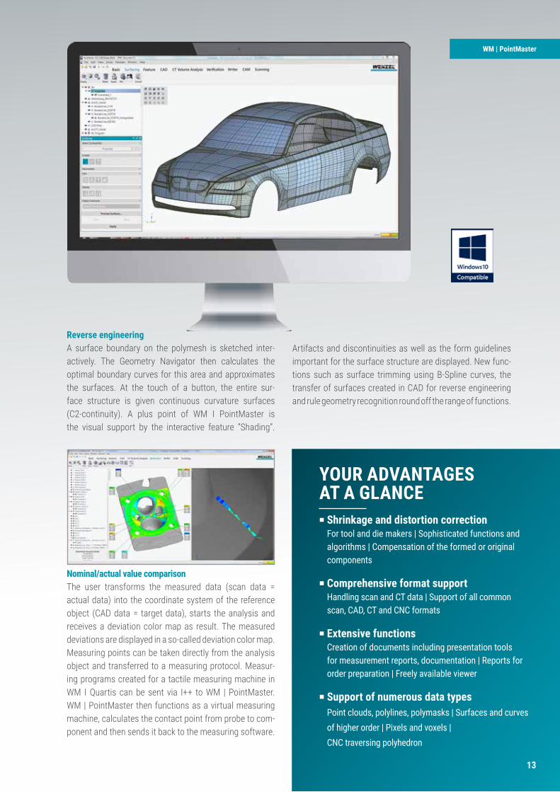
Nominal/actual value comparisonThe user transforms the measured data (scan data = actual data) into the coordinate system of the reference object (CAD data = target data), starts the analysis and receives a deviation color map as result. The measured deviations are displayed in a so-called deviation color map. Measuring points can be taken directly from the analysis object and transferred to a measuring protocol. Measur-ing programs created for a tactile measuring machine in WM I Quartis can be sent via I++ to WM | PointMaster. WM | PointMaster then functions as a virtual measuring machine, calculates the contact point from probe to com-ponent and then sends it back to the measuring software.
WM | PointMaster
Reverse engineeringA surface boundary on the polymesh is sketched inter-actively. The Geometry Navigator then calculates the optimal boundary curves for this area and approximates the surfaces. At the touch of a button, the entire sur-face structure is given continuous curvature surfaces (C2-continuity). A plus point of WM I PointMaster is the visual support by the interactive feature “Shading”.
Artifacts and discontinuities as well as the form guidelines important for the surface structure are displayed. New func-tions such as surface trimming using B-Spline curves, the transfer of surfaces created in CAD for reverse engineering and rule geometry recognition round off the range of functions.
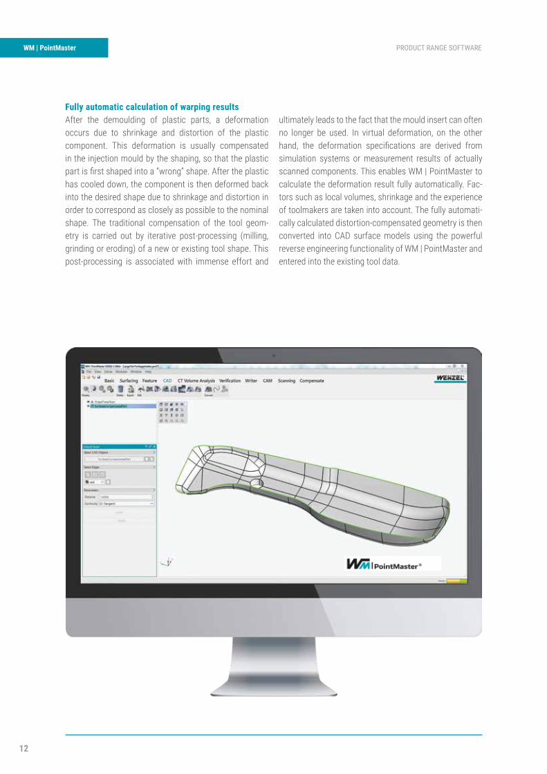
Fully automatic calculation of warping resultsAfter the demoulding of plastic parts, a deformation occurs due to shrinkage and distortion of the plastic component. This deformation is usually compensated in the injection mould by the shaping, so that the plastic part is first shaped into a “wrong” shape. After the plastic has cooled down, the component is then deformed back into the desired shape due to shrinkage and distortion in order to correspond as closely as possible to the nominal shape. The traditional compensation of the tool geom-etry is carried out by iterative post-processing (milling, grinding or eroding) of a new or existing tool shape. This post-processing is associated with immense effort and
ultimately leads to the fact that the mould insert can often no longer be used. In virtual deformation, on the other hand, the deformation specifications are derived from simulation systems or measurement results of actually scanned components. This enables WM | PointMaster to calculate the deformation result fully automatically. Fac-tors such as local volumes, shrinkage and the experience of toolmakers are taken into account. The fully automati-cally calculated distortion-compensated geometry is then converted into CAD surface models using the powerful reverse engineering functionality of WM | PointMaster and entered into the existing tool data.
WENZEL GESAMTKATALOG KMG Produktsegment
P Shrinkage and distortion correctionFor tool and die makers | Sophisticated functions andalgorithms | Compensation of the formed or originalcomponents
P Comprehensive format supportHandling scan and CT data | Support of all commonscan, CAD, CT and CNC formats
P Extensive functionsCreation of documents including presentation toolsfor measurement reports, documentation | Reports fororder preparation | Freely available viewer
P Support of numerous data typesPoint clouds, polylines, polymasks | Surfaces and curvesof higher order | Pixels and voxels |CNC traversing polyhedron
YOUR ADVANTAGES AT A GLANCE
Nominal/actual value comparisonThe user transforms the measured data (scan data = actual data) into the coordinate system of the reference object (CAD data = target data), starts the analysis and receives a deviation color map as result. The measured deviations are displayed in a so-called deviation color map. Measuring points can be taken directly from the analysis object and transferred to a measuring protocol. Measur-ing programs created for a tactile measuring machine in WM I Quartis can be sent via I++ to WM | PointMaster. WM | PointMaster then functions as a virtual measuring machine, calculates the contact point from probe to com-ponent and then sends it back to the measuring software.
WM | PointMaster
Reverse engineeringA surface boundary on the polymesh is sketched inter-actively. The Geometry Navigator then calculates the optimal boundary curves for this area and approximates the surfaces. At the touch of a button, the entire sur-face structure is given continuous curvature surfaces (C2-continuity). A plus point of WM I PointMaster is the visual support by the interactive feature “Shading”.
Artifacts and discontinuities as well as the form guidelines important for the surface structure are displayed. New func-tions such as surface trimming using B-Spline curves, the transfer of surfaces created in CAD for reverse engineering and rule geometry recognition round off the range of functions.
13
14
WM | Gear PRODUCT RANGE SOFTWAREWM | GEAR & GEAR Analyzer
WM | GEAR & GEAR AnalyzerTHE ALL-ROUNDER FOR GEAR MEASUREMENT
WM | Gear, together with the WM | Gear Ana-lyzer is the innovative software package for data acquisition, measurement and evaluation of involute gears with coordinate measuring machines. Users can use the extensive possibilities of the measuring software WM | Use Quartis without additional training effort (e.g.
probe management, calibration of probes, determination of the workpiece position and determination of the rotary table system). Communication between WM | Gear and WM | Gear Analyzer is based on the open GDE standard (VDI / VDE Guideline 2610).
HIGHLIGHTS
Profi le inspectionExtensive parameterization of the measuring tasks. All common profi le characteristics can be determined. Pro-fi le testing on any number of teeth possible. Several profi le inspections on one tooth possible. Profi le corrections can be selected separately for each measuring position (convexity, head/foot relief, nominal inclination, K-template, design pro-fi le).
Flank line testingExtensive parameterization of the measuring tasks. All common edge line characteristics can be determined. Flank line inspection on any number of teeth possible. Several fl ank line inspections on one tooth possible. Flank corrections can be selected for each measuring position (crowning, end relief, nominal inclination, K-template, design fl ank).
APPLICATION EXAMPLES
Spur and helical gears with involute profi le, internal and external gears.
Gears Bearings and clutches Shafts and axles
P User-friendly data management Input of geometry data, measuring tasks, evaluationregulations and tolerances | Any number of workpiecescan be saved | Import / export of gear data
P Extensive evaluation possibilitiesSupport of recognized standards | Free tolerances foreach feature possible | Transparent filter configuration |Company standards possible on request
P Interactive measurement sheet displayOver-height automatic / fix | Stretching automatic / fix| mm / inch switching | Subsequent modification of themeasurement sheet form | Temporary switching of theoutput language | Archiving of measurement results inPDF format | Coupling to statistical system possible
P High flexibilityFully automatic measuring sequence | Evaluation andpresentation parameters can be modified subsequently| Manufacturer-independent evaluation of measurementresults | CNC traversing polyhedron
YOUR ADVANTAGESAT A GLANCE
Determination of absolute dimensionsThe following features are possible at up to three differenttooth positions:Diameter of tip circleBase circle diameter•Ball dimension•Two-ball dimension•Single roll dimension•Double roll dimension•Tooth width•Tooth thickness
WM | GEAR & GEAR Analyzer
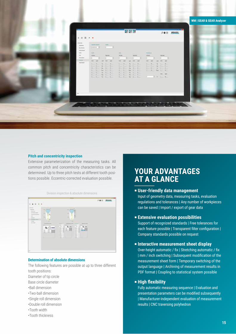
Pitch and concentricity inspectionExtensive parameterization of the measuring tasks. All common pitch and concentricity characteristics can be determined. Up to three pitch tests at different tooth posi-tions possible. Eccentric-corrected evaluation possible.
Division inspection & absolute dimensions
PRODUKTSEGMENT SOFTWARE WM | GearWM | GEAR & GEAR Analyzer
WM | GEAR & GEAR AnalyzerTHE ALL-ROUNDER FOR GEAR MEASUREMENT
WM | Gear, together with the WM | Gear Ana-lyzer is the innovative software package for data acquisition, measurement and evaluation of involute gears with coordinate measuring machines. Users can use the extensive possibilities of the measuring software WM | Use Quartis without additional training effort (e.g.
probe management, calibration of probes, determination of the workpiece position and determination of the rotary table system). Communication between WM | Gear and WM | Gear Analyzer is based on the open GDE standard (VDI / VDE Guideline 2610).
HIGHLIGHTS
Profile inspectionExtensive parameterization of the measuring tasks. Allcommon profile characteristics can be determined. Pro-file testing on any number of teeth possible. Several profileinspections on one tooth possible. Profile corrections can beselected separately for each measuring position (convexity,head/foot relief, nominal inclination, K-template, design pro-file).
Flank line testingExtensive parameterization of the measuring tasks. All common edge line characteristics can be determined. Flank line inspection on any number of teeth possible. Several flank line inspections on one tooth possible. Flank corrections can be selected for each measuring position (crowning, end relief, nominal inclination, K-template, design flank).
APPLICATION EXAMPLES
Spur and helical gears with involute profile, internal and external gears.
Gears Bearings and clutches Shafts and axles
P User-friendly data managementInput of geometry data, measuring tasks, evaluationregulations and tolerances | Any number of workpiecescan be saved | Import / export of gear data
P Extensive evaluation possibilitiesSupport of recognized standards | Free tolerances foreach feature possible | Transparent fi lter confi guration | Company standards possible on request
P Interactive measurement sheet displayOver-height automatic / fi x | Stretching automatic / fi x| mm / inch switching | Subsequent modifi cation of the measurement sheet form | Temporary switching of theoutput language | Archiving of measurement results inPDF format | Coupling to statistical system possible
P High fl exibilityFully automatic measuring sequence | Evaluation andpresentation parameters can be modifi ed subsequently | Manufacturer-independent evaluation of measurementresults | CNC traversing polyhedron
YOUR ADVANTAGES AT A GLANCE
Determination of absolute dimensionsThe following features are possible at up to three different tooth positions:Diameter of tip circleBase circle diameter•Ball dimension•Two-ball dimension•Single roll dimension•Double roll dimension•Tooth width•Tooth thickness
WM | GEAR & GEAR Analyzer
Pitch and concentricity inspectionExtensive parameterization of the measuring tasks. All common pitch and concentricity characteristics can be determined. Up to three pitch tests at different tooth posi-tions possible. Eccentric-corrected evaluation possible.
Division inspection & absolute dimensions
15
16
WM | BLADE Analyzer PRODUCT RANGE SOFTWARE
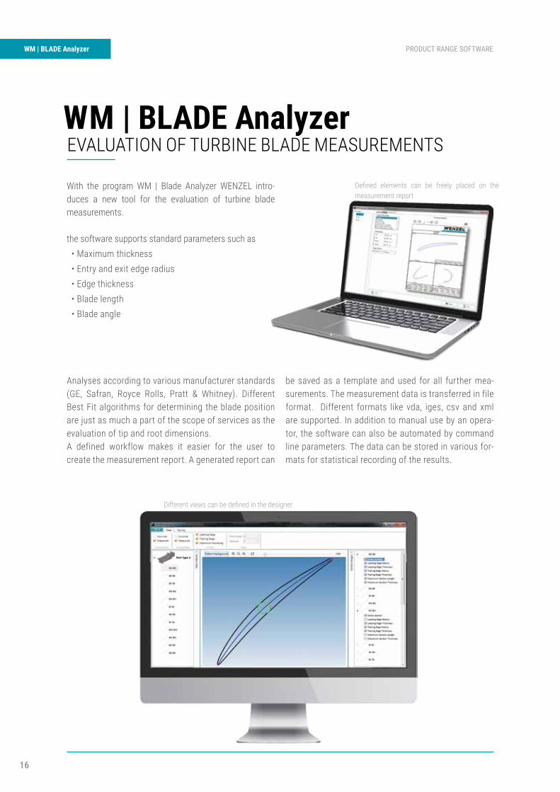
Analyses according to various manufacturer standards (GE, Safran, Royce Rolls, Pratt & Whitney). Different Best Fit algorithms for determining the blade position are just as much a part of the scope of services as the evaluation of tip and root dimensions.A defined workflow makes it easier for the user to create the measurement report. A generated report can
be saved as a template and used for all further mea-surements. The measurement data is transferred in file format. Different formats like vda, iges, csv and xml are supported. In addition to manual use by an opera-tor, the software can also be automated by command line parameters. The data can be stored in various for-mats for statistical recording of the results.
Different views can be defined in the designer
Defined elements can be freely placed on the measurement report
WM | BLADE AnalyzerEVALUATION OF TURBINE BLADE MEASUREMENTS
With the program WM | Blade Analyzer WENZEL intro-duces a new tool for the evaluation of turbine blade measurements.
the software supports standard parameters such as• Maximum thickness• Entry and exit edge radius• Edge thickness• Blade length• Blade angle
109
PRODUCT RANGE SOFTWARE WM | BLADE Analyzer
18
KMG Produktsegment PRODUCT RANGE SOFTWAREWM | SYS Analyzer
FEATURES
P Networking of local and global information of all connected measuring machines
P Intuitive interface and usability
P Automatic backup of all information, e.g. machine data and data from the measuring environment
P Possibilities of further analyses
P Platform independent usage and encryption
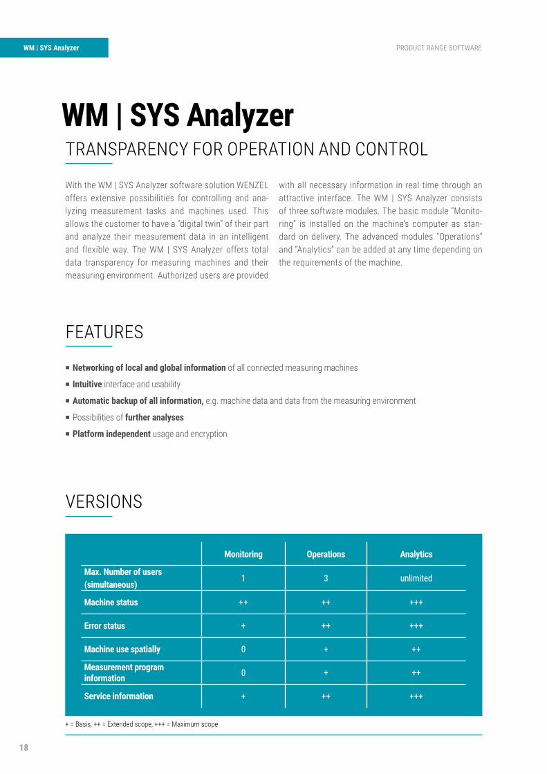
VERSIONS
WM | SYS AnalyzerTRANSPARENCY FOR OPERATION AND CONTROL
With the WM | SYS Analyzer software solution WENZEL offers extensive possibilities for controlling and ana-lyzing measurement tasks and machines used. This allows the customer to have a “digital twin” of their part and analyze their measurement data in an intelligent and flexible way. The WM | SYS Analyzer offers total data transparency for measuring machines and their measuring environment. Authorized users are provided
with all necessary information in real time through an attractive interface. The WM | SYS Analyzer consists of three software modules. The basic module “Monito-ring” is installed on the machine’s computer as stan-dard on delivery. The advanced modules “Operations” and “Analytics” can be added at any time depending on the requirements of the machine.
Monitoring Operations Analytics
Max. Number of users (simultaneous)
1 3 unlimited
Machine status ++ ++ +++
Error status + ++ +++
Machine use spatially 0 + ++
Measurement program information 0 + ++
Service information + ++ +++
+ = Basis, ++ = Extended scope, +++ = Maximum scope
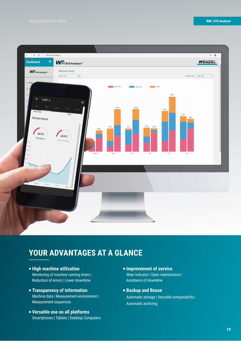
WM | SYS Analyzer
P High machine utilizationMonitoring of machine running times |Reduction of errors | Lower downtime
P Transparency of informationMachine data | Measurement environment |Measurement sequences
P Versatile use on all platformsSmartphones | Tablets | Desktop Computers
P Improvement of serviceWear indicator | Open maintenance |Avoidance of downtime
P Backup and ReuseAutomatic storage | Versatile comparability |Automatic archiving
YOUR ADVANTAGES AT A GLANCE
PRODUCT RANGE SOFTWARE
19
20
WM | Generator PRODUCT RANGE SOFTWAREWM | Generator
FEATURES
Import various CAD formats, including their semantic PMIs
P Siemens NX
P CATIA V5
P Inventor
P SolidWorks
P STEP AP242
WM | GENERATORAUTOMATED MEASUREMENT & EVALUATION
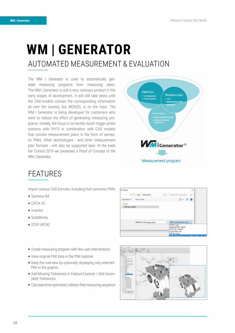
The WM | Generator is used to automatically gen-erate measuring programs from measuring plans. The WM | Generator is still a very visionary product in the early stages of development. It will still take years until the CAD-models contain the corresponding information all over the country, but WENZEL is on the topic. The WM | Generator is being developed for customers who want to reduce the effort of generating measuring pro-grams. Initially, the focus is on tactile, touch trigger probe systems with PH10 in combination with CAD models that contain measurement plans in the form of seman-tic PMIs. Other technologies - and other measurement plan formats - will also be supported later. At the trade fair Control 2019 we presented a Proof of Concept of the WM | Generator.
P Create measuring program with few user interventions
P View original PMI data in the PMI ExplorerP Keep the overview by optionally displaying only selected
PMI in the graphic.P Add Missing Tolerances in Feature Explorer / Add Incom- plete TolerancesP Calculate time-optimized, collision-free measuring sequence
FUNCTION
P Reduce the time required to generate measuring programs
P Improve resource utilization through time-optimized measuring program procedure
P Electronic data exchange saves time and reduces transmission errors
P Creating time for the essentials by automating processes that can be automated
YOUR ADVANTAGES AT A GLANCE
WM | Generator
When importing the CAD model, not only the CAD data but alsothe semantic PMI are converted.
If necessary, PMI can still be added or edited.
The measurement plan is automatically generated from thePMI - the basis for the measurement sequence. For the char-acteristics to be evaluated and the corresponding elements tobe recorded, the measurement strategy can still be edited inthe measurement plan if required. Characteristics that are notto be evaluated in the measuring program are deactivated.
Based on the measurement plan, the measurement proce-dure is calculated, which represents the preliminary stage forprogram generation. From the measurement plan, the WM |Generator generates the measurement program, which can beexecuted in WM | Quartis..
PRODUCT RANGE SOFTWARE WM | GeneratorWM | Generator
FEATURES
Import various CAD formats, including their semantic PMIs
P Siemens NX
P CATIA V5
P Inventor
P SolidWorks
P STEP AP242
WM | GENERATORAUTOMATED MEASUREMENT & EVALUATION
The WM | Generator is used to automatically gen-erate measuring programs from measuring plans.The WM | Generator is still a very visionary product in the early stages of development. It will still take years until the CAD-models contain the corresponding information all over the country, but WENZEL is on the topic. The WM | Generator is being developed for customers who want to reduce the effort of generating measuring pro-grams. Initially, the focus is on tactile, touch trigger probe systems with PH10 in combination with CAD models that contain measurement plans in the form of seman-tic PMIs. Other technologies - and other measurement plan formats - will also be supported later. At the tradefair Control 2019 we presented a Proof of Concept of theWM | Generator.
P Create measuring program with few user interventions
P View original PMI data in the PMI ExplorerP Keep the overview by optionally displaying only selected
PMI in the graphic.P Add Missing Tolerances in Feature Explorer / Add Incom-
plete TolerancesP Calculate time-optimized, collision-freemeasuring sequence
FUNCTION
P Reduce the time required to generatemeasuring programs
P Improve resource utilization through time-optimized measuring program procedure
P Electronic data exchange saves time andreduces transmission errors
P Creating time for the essentials byautomating processes that can beautomated
YOUR ADVANTAGES AT A GLANCE
WM | Generator
When importing the CAD model, not only the CAD data but also the semantic PMI are converted.
If necessary, PMI can still be added or edited.
The measurement plan is automatically generated from the PMI - the basis for the measurement sequence. For the char-acteristics to be evaluated and the corresponding elements to be recorded, the measurement strategy can still be edited in the measurement plan if required. Characteristics that are not to be evaluated in the measuring program are deactivated.
Based on the measurement plan, the measurement proce-dure is calculated, which represents the preliminary stage for program generation. From the measurement plan, the WM | Generator generates the measurement program, which can be executed in WM | Quartis..
21
WENZEL Group GmbH & Co. KG | Werner-Wenzel-Straße | 97859 Wiesthal | GermanyTelefon: +49 6020 201-0 | Fax: +49 6020 201-1999 | E-Mail: [email protected] www.wenzel-group.com
INNOVATION MEETS TRADITIONThe WENZEL Group is a market leader in innovative Metrology. WENZEL offers a comprehensive product portfolio in the fi elds of Coordinate Metrology, Computed Tomography and Optical High Speed Scanning. The technology of WENZEL is used in all industries, including the automotive sector, aeronautics, power generation and
medicine. WENZEL looks at today on an installed base of more than 10,000 machines worldwide. Subsidiaries and agencies in more than 50 countries support sales andprovide after-sales service for our customers. The WENZEL Group today employs more than 600 people.
YOUR LOCAL CONTACT Wenzel America Ltd28700 Beck RoadWixom MI 48451 USAPhone: +1 (248) 295 4300E-Mail: [email protected]
www.wenzelamerica.com
Follow us & stay up to date!
Gene
ral-C
atal
ogue
_EN_
01 2
019-
10 |
© W
ENZE
L Gr
oup
GmbH
& C
o. K
G Su
bjec
t to
tech
nica
l mod
ifi c
atio
n an
d to
cha
nges
in s
cope
and
des
ign