Embed Size (px)
Citation preview
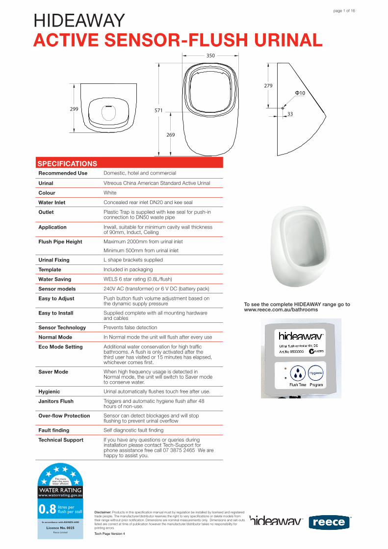
HIDEAWAYACTIVE SENSOR-FLUSH URINAL
To see the complete HIDEAWAY range go to www.reece.com.au/bathrooms
Disclaimer: Products in this specification manual must by regulation be installed by licensed and registered trade people. The manufacturer/distributor reserves the right to vary specifications or delete models from their range without prior notification. Dimensions are nominal measurements only. Dimensions and set-outs listed are correct at time of publication however the manufacturer/distributor takes no responsibility for printing errors.
Tech Page Version 4
SPECIFICATIONSRecommended Use Domestic, hotel and commercial
Urinal Vitreous China American Standard Active Urinal
Colour White
Water Inlet Concealed rear inlet DN20 and kee seal
Outlet Plastic Trap is supplied with kee seal for push-in connection to DN50 waste pipe
Application Inwall, suitable for minimum cavity wall thickness of 90mm, Induct, Ceiling
Flush Pipe Height Maximum 2000mm from urinal inlet
Minimum 500mm from urinal inlet
Urinal Fixing L shape brackets supplied
Template Included in packaging
Water Saving WELS 6 star rating (0.8L/flush)
Sensor models 240V AC (transformer) or 6 V DC (battery pack)
Easy to Adjust Push button flush volume adjustment based on the dynamic supply pressure
Easy to Install Supplied complete with all mounting hardware and cables
Sensor Technology Prevents false detection
Normal Mode In Normal mode the unit will flush after every use
Eco Mode Setting Additional water conservation for high traffic bathrooms. A flush is only activated after the third user has visited or 15 minutes has elapsed, whichever comes first.
Saver Mode When high frequency usage is detected in Normal mode, the unit will switch to Saver mode to conserve water.
Hygienic Urinal automatically flushes touch free after use.
Janitors Flush Triggers and automatic hygiene flush after 48 hours of non-use.
Over-flow Protection Sensor can detect blockages and will stop flushing to prevent urinal overflow
Fault finding Self diagnostic fault finding
Technical Support If you have any questions or queries during installation please contact Tech-Support for phone assistance free call 07 3875 2465 We are happy to assist you.
Dear Customer,This is the warranty by Reece Pty. Ltd. relating to this product. Please keep it together with your purchase receipt. In the unlikely event of a query please contact your nearest Reece Plumbing Centre.
WarrantyYou have purchased a quality product from Reece Australia. This product is covered by a twelve month warranty. This warranty covers faults in the product construction, material and assembly. Faulty products will be repaired or exchanged free of charge. Faulty items be-come our property.This warranty does not include faults caused by:• Unsuitable or improper use• Incorrect installation • Installation or part installation by the purchaser or any person other
than a LICENSED PLUMBER or tradesman
• Normal wear and tear• Inadequate or complete lack of maintenance
Cleaning RecommendationsAny sanitaryware should not be cleaned with abrasive materials eg. steel wool/scourers. Do not use any corrosive or abrasive cleaning agents containing acids or scouring agents. In the event of a warranty claim, we will replace or repair defective prod-ucts, or pay for the cost of having defective products repaired or replaced, but will not be liable for any injury to any person, damage to any property, any indirect or consequential loss, or in any other respect.
WARRANTY & CARE DETAILS
571
Φ10
269
279
350
33299
Disclaimer:Products in this speci cation manual must by regulation be installed by licensed and registered trade people. The manufacturer/dis-tributor reserves the right to vary speci cations or delete models from their range without prior noti cation. Dimensions and set-outs listed are correct at time of publication however the manufacturer/distributor takes no responsibility for printing errors.Tech Page Version 1
WMKT21654.4
Watermark WMKT21654.4
Fixing To wall with L shape bracket supplied
Standards AS/NZS 6400:2005Warranty 12 months warranty (see below)
Template Including in packaging
WELS 3 Star rating, average ush 1.2 litres
expansions coupling
page 1 of 16
The more stars the more water efficient
WATER RATINGwww.waterrating.gov.au
In accordance with AS/NZS 6400
Licence No. 0025Reece Limited
0.8 litres per flush per stall
HIDEAWAYACTIVE SENSOR-FLUSH URINAL
Plumbers, please ensure a copy of the installation instructions is left with the end user for future reference
HIDEAWAY ACTIVE SENSOR-FLUSH URINAL
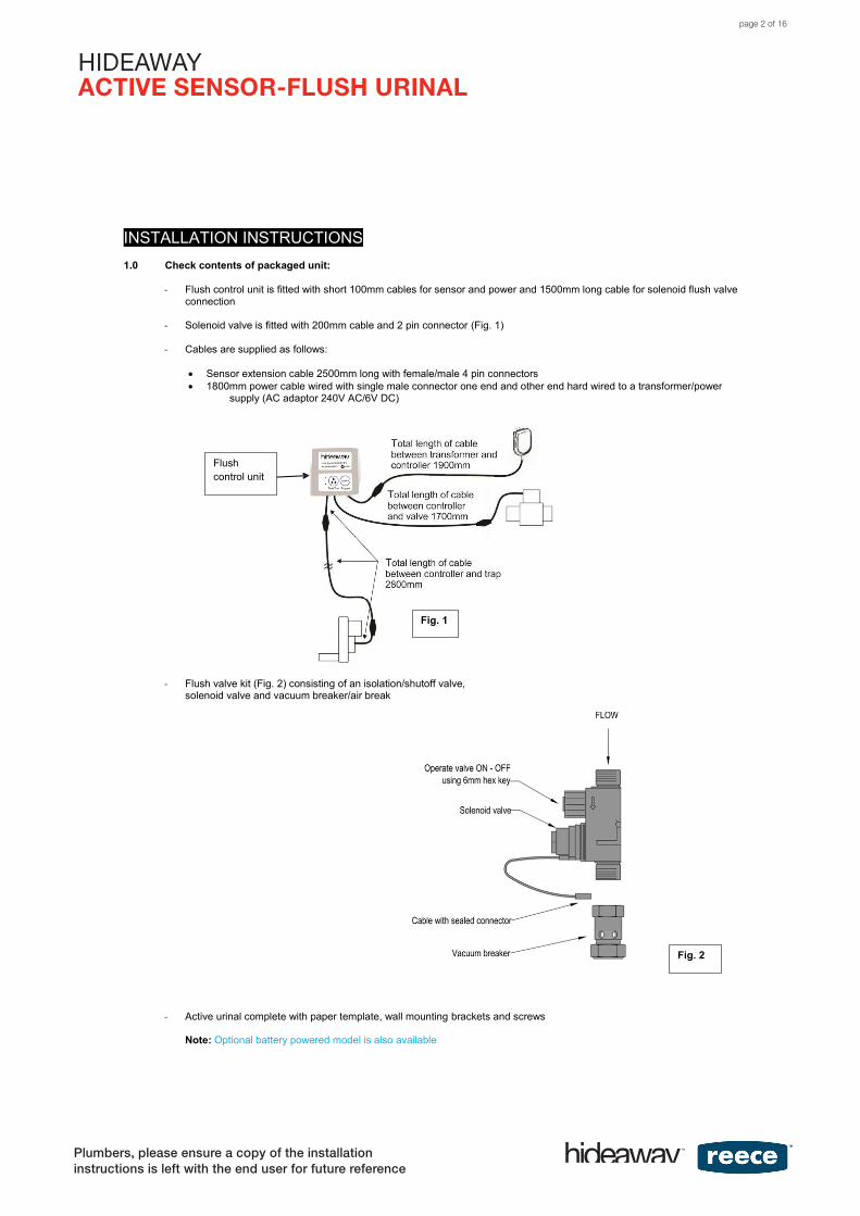
INSTALLATION INSTRUCTIONS 1.0 Check contents of packaged unit:
- Flush control unit is fitted with short 100mm cables for sensor and power and 1500mm long cable for solenoid flush valve
connection
- Solenoid valve is fitted with 200mm cable and 2 pin connector (Fig. 1)
- Cables are supplied as follows:
Sensor extension cable 2500mm long with female/male 4 pin connectors 1800mm power cable wired with single male connector one end and other end hard wired to a transformer/power
supply (AC adaptor 240V AC/6V DC)
- Flush valve kit (Fig. 2) consisting of an isolation/shutoff valve, solenoid valve and vacuum breaker/air break
- Active urinal complete with paper template, wall mounting brackets and screws Note: Optional battery powered model is also available
Flush control unit
Fig. 1
Fig. 2
page 2 of 16
HIDEAWAYACTIVE SENSOR-FLUSH URINAL
Plumbers, please ensure a copy of the installation instructions is left with the end user for future reference
HIDEAWAYACTIVE SENSOR-FLUSH URINAL
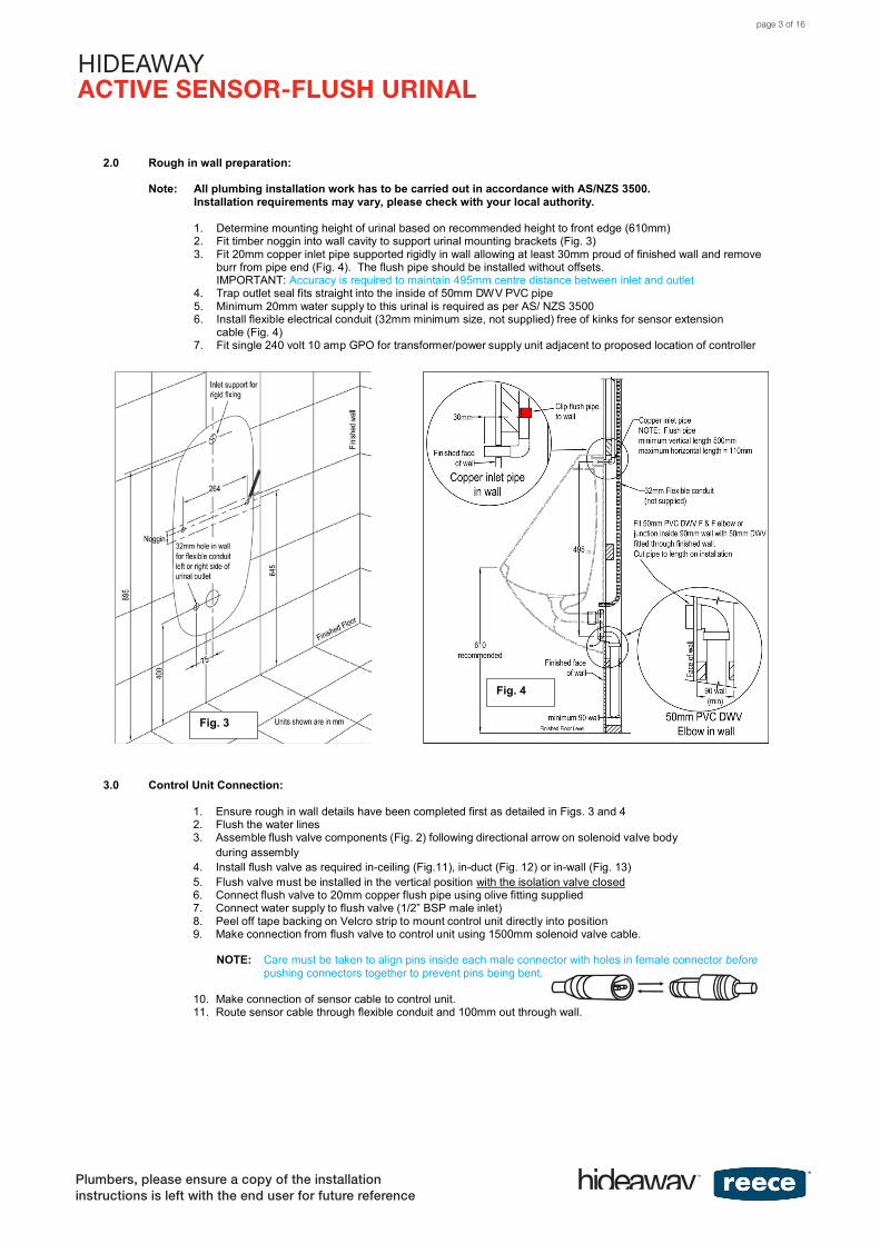
2.0 Rough in wall preparation:
Note: All plumbing installation work has to be carried out in accordance with AS/NZS 3500.Installation requirements may vary, please check with your local authority.
1. Determine mounting height of urinal based on recommended height to front edge (610mm)2. Fit timber noggin into wall cavity to support urinal mounting brackets (Fig. 3)3. Fit 20mm copper inlet pipe supported rigidly in wall allowing at least 30mm proud of finished wall and remove
burr from pipe end (Fig. 4). The flush pipe should be installed without offsets.IMPORTANT: Accuracy is required to maintain 495mm centre distance between inlet and outlet
4. Trap outlet seal fits straight into the inside of 50mm DWV PVC pipe5. Minimum 20mm water supply to this urinal is required as per AS/ NZS 35006. Install flexible electrical conduit (32mm minimum size, not supplied) free of kinks for sensor extension
cable (Fig. 4)7. Fit single 240 volt 10 amp GPO for transformer/power supply unit adjacent to proposed location of controller
3.0 Control Unit Connection:
1. Ensure rough in wall details have been completed first as detailed in Figs. 3 and 42. Flush the water lines3. Assemble flush valve components (Fig. 2) following directional arrow on solenoid valve body
during assembly4. Install flush valve as required in-ceiling (Fig.11), in-duct (Fig. 12) or in-wall (Fig. 13)5. Flush valve must be installed in the vertical position with the isolation valve closed6. Connect flush valve to 20mm copper flush pipe using olive fitting supplied7. Connect water supply to flush valve (1/2” BSP male inlet)8. Peel off tape backing on Velcro strip to mount control unit directly into position9. Make connection from flush valve to control unit using 1500mm solenoid valve cable.
NOTE: Care must be taken to align pins inside each male connector with holes in female connector before pushing connectors together to prevent pins being bent.
10. Make connection of sensor cable to control unit.11. Route sensor cable through flexible conduit and 100mm out through wall.
Fig. 3
Fig. 4
page 3 of 16
HIDEAWAYACTIVE SENSOR-FLUSH URINAL
Plumbers, please ensure a copy of the installation instructions is left with the end user for future reference
HIDEAWAY ACTIVE SENSOR-FLUSH URINAL
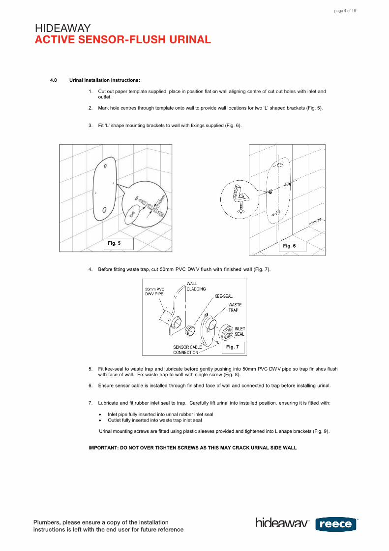
4.0 Urinal Installation Instructions:
1. Cut out paper template supplied, place in position flat on wall aligning centre of cut out holes with inlet and outlet.
2. Mark hole centres through template onto wall to provide wall locations for two ‘L’ shaped brackets (Fig. 5).
3. Fit ‘L’ shape mounting brackets to wall with fixings supplied (Fig. 6).
4. Before fitting waste trap, cut 50mm PVC DW V flush with finished wall (Fig. 7).
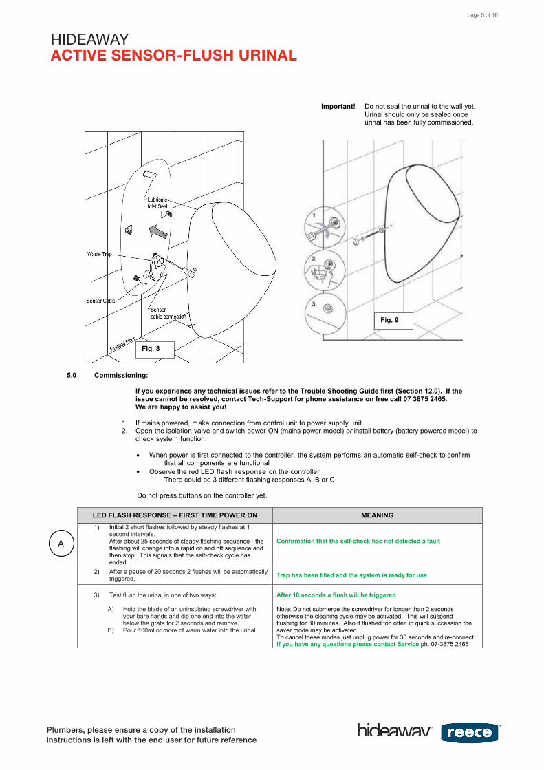
5. Fit kee-seal to waste trap and lubricate before gently pushing into 50mm PVC DW V pipe so trap finishes flush with face of wall. Fix waste trap to wall with single screw (Fig. 8).
6. Ensure sensor cable is installed through finished face of wall and connected to trap before installing urinal.
7. Lubricate and fit rubber inlet seal to trap. Carefully lift urinal into installed position, ensuring it is fitted with:
Inlet pipe fully inserted into urinal rubber inlet seal Outlet fully inserted into waste trap inlet seal
Urinal mounting screws are fitted using plastic sleeves provided and tightened into L shape brackets (Fig. 9).
IMPORTANT: DO NOT OVER TIGHTEN SCREWS AS THIS MAY CRACK URINAL SIDE WALL
Fig. 5 Fig. 6
Fig. 7
page 4 of 16
HIDEAWAYACTIVE SENSOR-FLUSH URINAL
Plumbers, please ensure a copy of the installation instructions is left with the end user for future reference
HIDEAWAYACTIVE SENSOR-FLUSH URINAL
A
Important! Do not seal the urinal to the wall yet. Urinal should only be sealed once urinal has been fully commissioned.
5.0 Commissioning:
If you experience any technical issues refer to the Trouble Shooting Guide first (Section 12.0). If the issue cannot be resolved, contact Tech-Support for phone assistance on free call 07 3875 2465. We are happy to assist you!
1. If mains powered, make connection from control unit to power supply unit.2. Open the isolation valve and switch power ON (mains power model) or install battery (battery powered model) to
check system function:
When power is first connected to the controller, the system performs an automatic self-check to confirmthat all components are functional
Observe the red LED flash response on the controllerThere could be 3 different flashing responses A, B or C
Do not press buttons on the controller yet.
LED FLASH RESPONSE – FIRST TIME POWER ON MEANING1) Initial 2 short flashes followed by steady flashes at 1
second intervals.After about 25 seconds of steady flashing sequence - theflashing will change into a rapid on and off sequence andthen stop. This signals that the self-check cycle hasended.
Confirmation that the self-check has not detected a fault
2) After a pause of 20 seconds 2 flushes will be automaticallytriggered. Trap has been filled and the system is ready for use
3) Test flush the urinal in one of two ways:
A) Hold the blade of an uninsulated screwdriver withyour bare hands and dip one end into the waterbelow the grate for 2 seconds and remove.
B) Pour 100ml or more of warm water into the urinal.
After 10 seconds a flush will be triggered
Note: Do not submerge the screwdriver for longer than 2 seconds otherwise the cleaning cycle may be activated. This will suspend flushing for 30 minutes. Also if flushed too often in quick succession the saver mode may be activated.To cancel these modes just unplug power for 30 seconds and re-connect. If you have any questions please contact Service ph. 07-3875 2465
Fig. 8
Fig. 9
page 5 of 16
HIDEAWAYACTIVE SENSOR-FLUSH URINAL
Plumbers, please ensure a copy of the installation instructions is left with the end user for future reference
HIDEAWAYACTIVE SENSOR-FLUSH URINAL
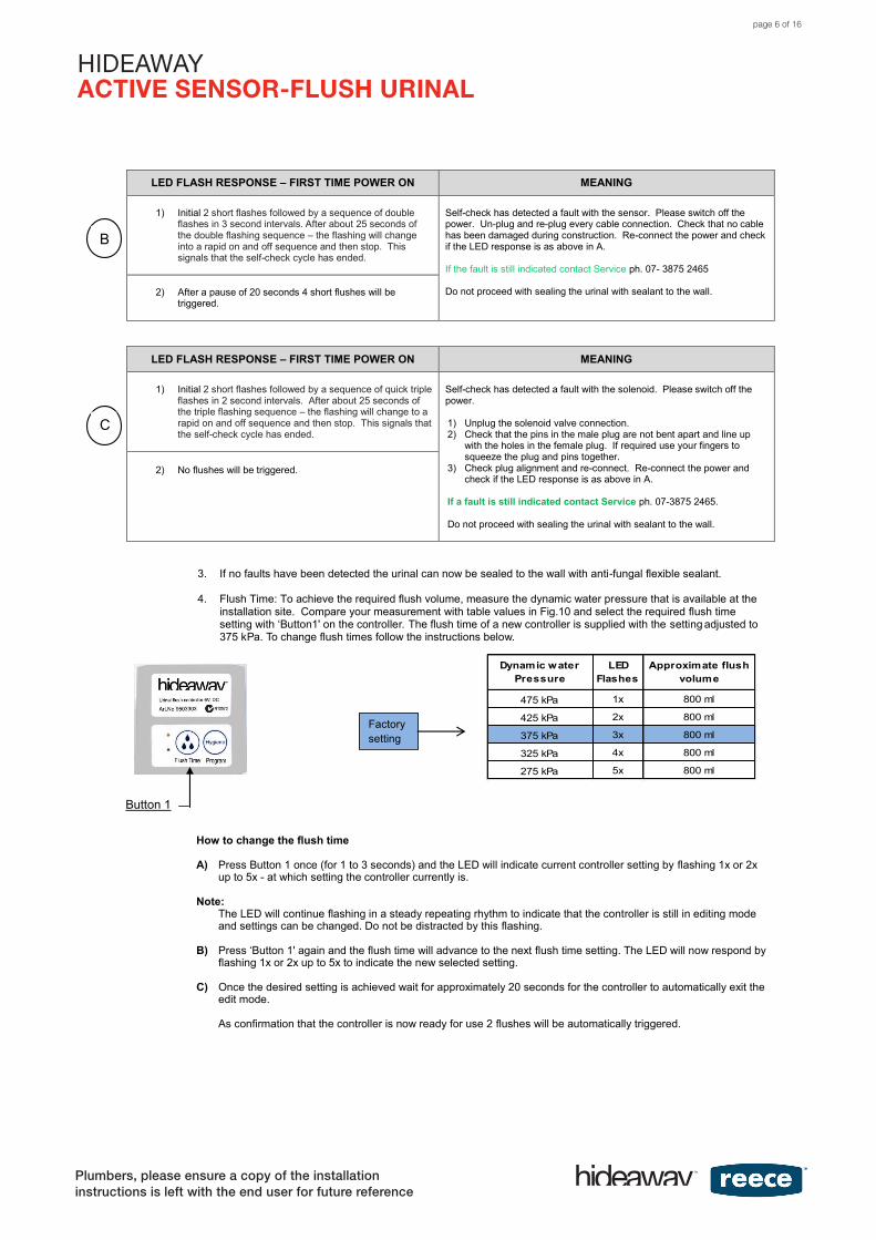
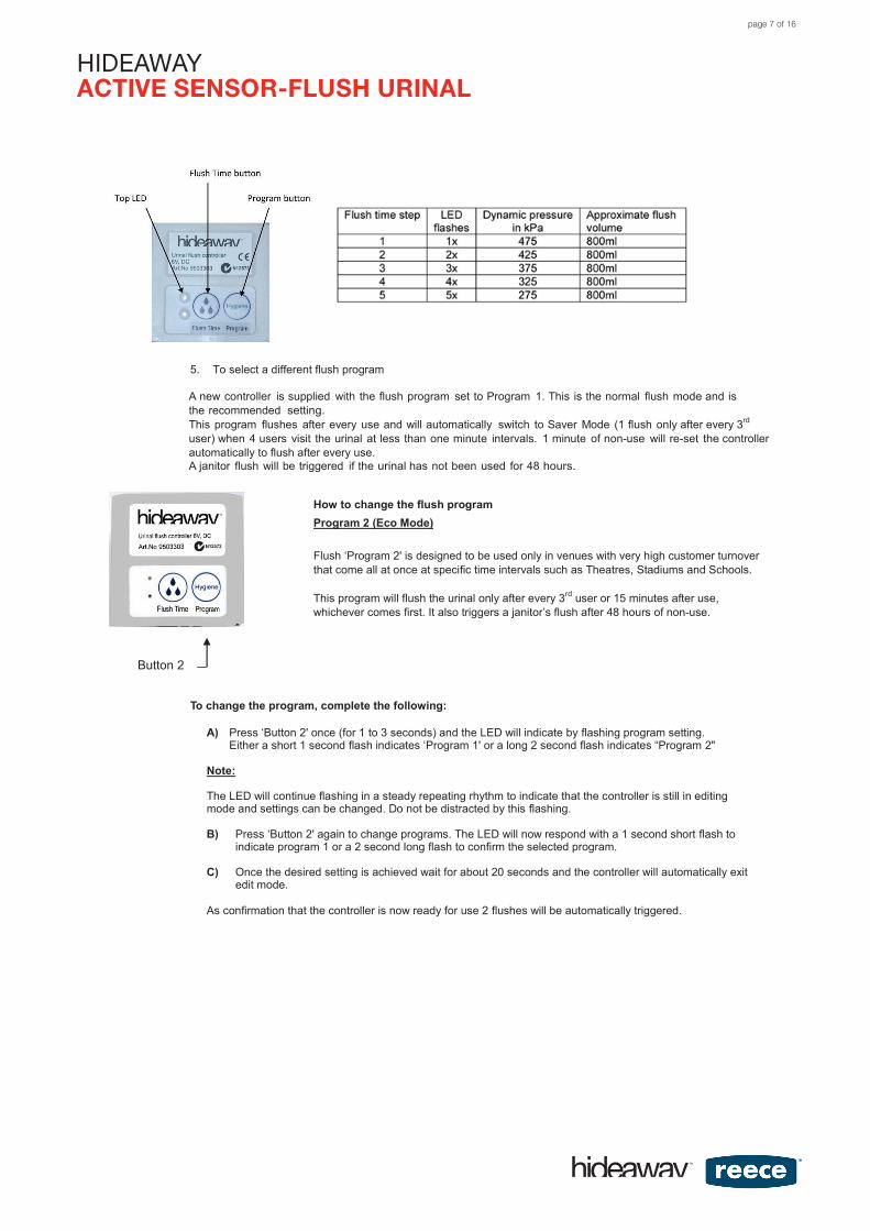
Dynamic water Pressure
LED Flashes
Approximate flush volume
475 kPa 1x 800 ml
425 kPa 2x 800 ml
375 kPa 3x 800 ml
325 kPa 4x 800 ml
275 kPa 5x 800 ml
LED FLASH RESPONSE – FIRST TIME POWER ON MEANING
1) Initial 2 short flashes followed by a sequence of doubleflashes in 3 second intervals. After about 25 seconds ofthe double flashing sequence – the flashing will changeinto a rapid on and off sequence and then stop. Thissignals that the self-check cycle has ended.
Self-check has detected a fault with the sensor. Please switch off the power. Un-plug and re-plug every cable connection. Check that no cable has been damaged during construction. Re-connect the power and check if the LED response is as above in A.
If the fault is still indicated contact Service ph. 07- 3875 2465
Do not proceed with sealing the urinal with sealant to the wall.2) After a pause of 20 seconds 4 short flushes will betriggered.
LED FLASH RESPONSE – FIRST TIME POWER ON MEANING
1) Initial 2 short flashes followed by a sequence of quick tripleflashes in 2 second intervals. After about 25 seconds ofthe triple flashing sequence – the flashing will change to arapid on and off sequence and then stop. This signals thatthe self-check cycle has ended.
Self-check has detected a fault with the solenoid. Please switch off the power.
1) Unplug the solenoid valve connection.2) Check that the pins in the male plug are not bent apart and line up
with the holes in the female plug. If required use your fingers tosqueeze the plug and pins together.
3) Check plug alignment and re-connect. Re-connect the power andcheck if the LED response is as above in A.
If a fault is still indicated contact Service ph. 07-3875 2465.
Do not proceed with sealing the urinal with sealant to the wall.
2) No flushes will be triggered.
3. If no faults have been detected the urinal can now be sealed to the wall with anti-fungal flexible sealant.
4. Flush Time: To achieve the required flush volume, measure the dynamic water pressure that is available at theinstallation site. Compare your measurement with table values in Fig.10 and select the required flush timesetting with ‘Button1' on the controller. The flush time of a new controller is supplied with the setting adjusted to375 kPa. To change flush times follow the instructions below.
How to change the flush time
A) Press Button 1 once (for 1 to 3 seconds) and the LED will indicate current controller setting by flashing 1x or 2xup to 5x - at which setting the controller currently is.
Note: The LED will continue flashing in a steady repeating rhythm to indicate that the controller is still in editing mode and settings can be changed. Do not be distracted by this flashing.
B) Press ‘Button 1' again and the flush time will advance to the next flush time setting. The LED will now respond byflashing 1x or 2x up to 5x to indicate the new selected setting.
C) Once the desired setting is achieved wait for approximately 20 seconds for the controller to automatically exit theedit mode.
As confirmation that the controller is now ready for use 2 flushes will be automatically triggered.
B
C
Factory setting
Button 1
page 6 of 16
HIDEAWAYACTIVE SENSOR-FLUSH URINAL
HIDEAWAYACTIVE SENSOR-FLUSH URINAL
5. To select a different flush program
A new controller is supplied with the flush program set to Program 1. This is the normal flush mode and isthe recommended setting.This program flushes after every use and will automatically switch to Saver Mode (1 flush only after every 3rd
user) when 4 users visit the urinal at less than one minute intervals. 1 minute of non-use will re-set the controller automatically to flush after every use. A janitor flush will be triggered if the urinal has not been used for 48 hours.
How to change the flush program Program 2 (Eco Mode)
Flush ‘Program 2' is designed to be used only in venues with very high customer turnover that come all at once at specific time intervals such as Theatres, Stadiums and Schools.
This program will flush the urinal only after every 3rd user or 15 minutes after use,whichever comes first. It also triggers a janitor’s flush after 48 hours of non-use.
Button 2
To change the program, complete the following:
A) Press ‘Button 2' once (for 1 to 3 seconds) and the LED will indicate by flashing program setting.Either a short 1 second flash indicates ‘Program 1' or a long 2 second flash indicates “Program 2"
Note:
The LED will continue flashing in a steady repeating rhythm to indicate that the controller is still in editing mode and settings can be changed. Do not be distracted by this flashing.
B) Press ‘Button 2' again to change programs. The LED will now respond with a 1 second short flash toindicate program 1 or a 2 second long flash to confirm the selected program.
C) Once the desired setting is achieved wait for about 20 seconds and the controller will automatically exitedit mode.
As confirmation that the controller is now ready for use 2 flushes will be automatically triggered.
page 7 of 16
HIDEAWAYACTIVE SENSOR-FLUSH URINAL
HIDEAWAYACTIVE SENSOR-FLUSH URINAL6.0 Cleaning:
Cleaning of the urinal is an important part of the regular maintenance. This should not just only involve the ceramic part of the urinal. Cleaning the trap and pipe connection at regular intervals is equally important.
Water can react with urine and form struvite. Struvite is a hard crystalline deposit that will form on the ceramic and inside the trap and pipe connection. Over time Struvite can build up creating a blockage. Struvite deposits have to be frequently removed with a suitable acidic type toilet cleaner at regular intervals.
Cleaning agents are more effective if they soak for a certain time (refer to the cleaning agent instructions). To assist with the soaking period, the controller is equipped with a cleaning cycle that suspends flushing for 30 minutes.
How to activate cleaning cycle in Program 1 (Normal Mode):
1) Hold the blade of a screwdriver with your bare hands (no gloves can be worn) into the water below the grate for 10seconds. Whilst still holding the rod in the water pour some of the cleaning agent into the water of the urinal.
2) Now remove the rod from the water. This will trigger two short flushes which will carry the cleaning agent to the back ofthe trap and pipe connection. Now the flushing is suspended for 30 minutes.
3) Add more of the cleaning agent to the water of the urinal. After 30 minutes a flush will automatically trigger and the urinalis ready for use.
How to clean in Program 2 (ECO Mode):
In Program 2 which flushes after every third user or approximately 15 minutes after use whichever is first, cleaning may be done within 15 minutes in 2 ways.
A) The cleaner can visually check if the urinal has been flushed.
If it has been flushed proceed as follows.
1) In a bucket mix the cleaning agent with some water (follow cleaning agent instructions) and pour into the urinal.
This will carry the cleaning agent into the back of the trap and pipe connection.
2) No longer disturb the urinal in any way for the next 15 minutes until it automatically flushes.
B) If it hasn’t been flushed proceed as follows.
1) Hold the blade of a screwdriver into the water for 2 seconds and remove.
Wait for 10 seconds to see if the urinal flushes. If not repeat the same procedure until it flushes.
2) In a bucket mix the cleaning agent with some water (follow cleaning agent instructions) and pour into the urinal.
This will carry the cleaning agent into the back of the trap and pipe connection.
3) No longer disturb the urinal in any way for the next 15 minutes until it automatically flushes.
7.0 Overflow Protection:
To avoid overflow in the case of a pipe blockage the urine sensing device will cease to activate further flushing once the urinalbowl has filled.
page 8 of 16
HIDEAWAYACTIVE SENSOR-FLUSH URINAL
Plumbers, please ensure a copy of the installation instructions is left with the end user for future reference
HIDEAWAYACTIVE SENSOR-FLUSH URINAL
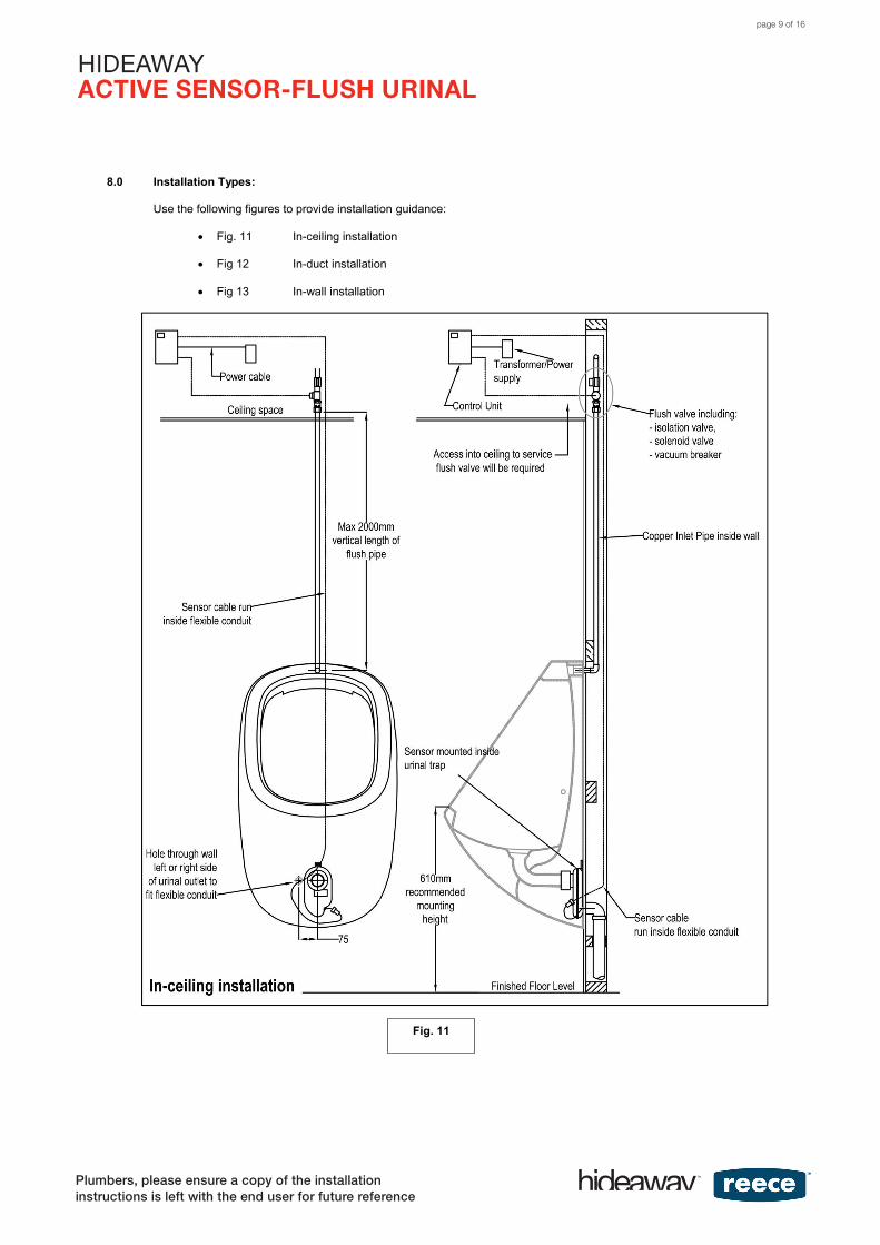
8.0 Installation Types:
Use the following figures to provide installation guidance:
Fig. 11 In-ceiling installation
Fig 12 In-duct installation
Fig 13 In-wall installation
Fig. 11
page 9 of 16
HIDEAWAYACTIVE SENSOR-FLUSH URINAL
Plumbers, please ensure a copy of the installation instructions is left with the end user for future reference
HIDEAWAYACTIVE SENSOR-FLUSH URINAL
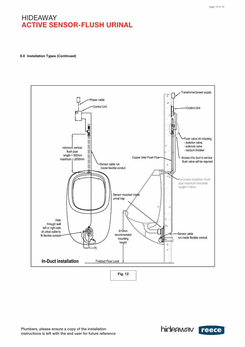
8.0 Installation Types (Continued)
Fig. 12
page 10 of 16
HIDEAWAYACTIVE SENSOR-FLUSH URINAL
HIDEAWAYACTIVE SENSOR-FLUSH URINAL
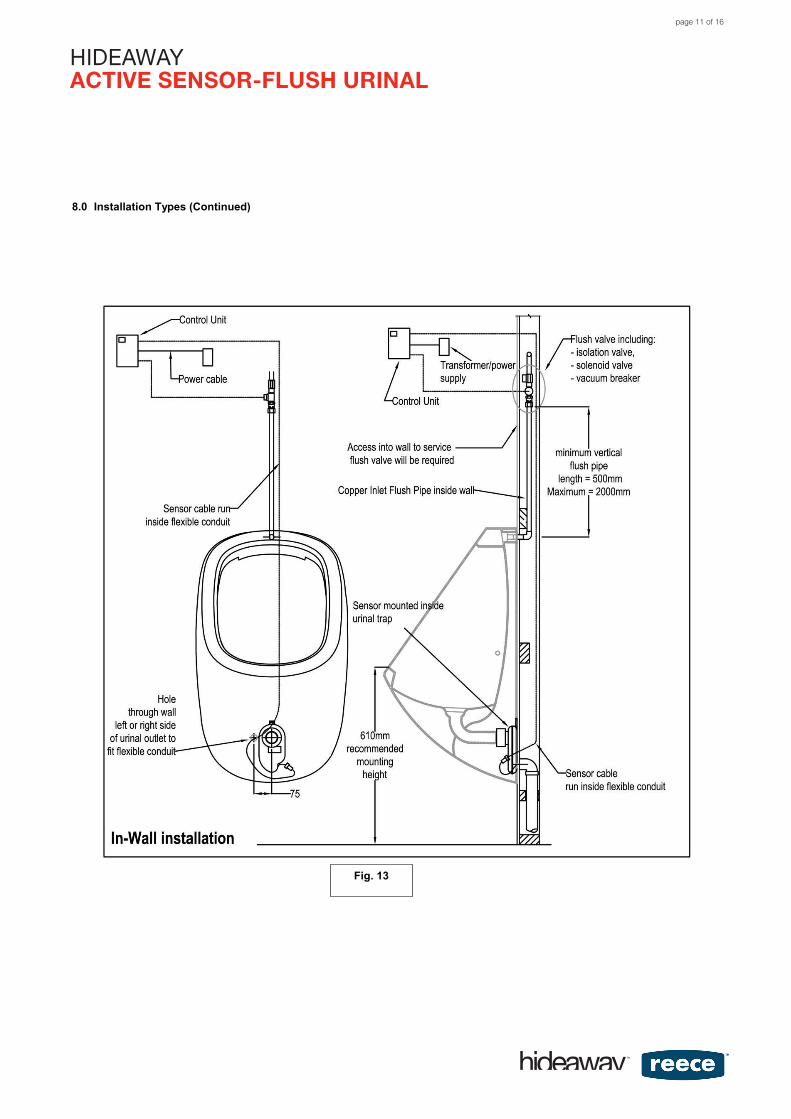
8.0 Installation Types (Continued)
Fig. 13
page 11 of 16
HIDEAWAYACTIVE SENSOR-FLUSH URINAL
Plumbers, please ensure a copy of the installation instructions is left with the end user for future reference
HIDEAWAYACTIVE SENSOR-FLUSH URINAL
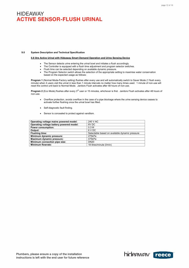
9.0 System Description and Technical Specification
0.8 litre Active Urinal with Hideaway Smart Demand Operation and Urine Sensing Device
• The Sensor detects urine entering the urinal bowl and initiates a flush accordingly.• The Controller is equipped with a flush time adjustment and program selector switches.• Flush time can be selected depending on available dynamic pressure.• The Program Selector switch allows the selection of the appropriate setting to maximise water conservation
based on the expected usage as follows:
Program 1 (Normal Mode-Factory setting) flushes after every use and will automatically switch to Saver Mode (1 flush every minute) when 4 users visit the urinal in less than 1 minute intervals no matter how many times used. 1 minute of non-use will reset the control unit back to Normal Mode. Janitors Flush activates after 48 hours of non-use.
Program 2 (Eco Mode) flushes after every 3rd user or 15 minutes, whichever is first. Janitors Flush activates after 48 hours of non-use.
• Overflow protection, avoids overflow in the case of a pipe blockage where the urine sensing device ceases to activate further flushing once the urinal bowl has filled.
• Self-diagnostic fault finding.
• Sensor is concealed to protect against vandlism.
Operating voltage mains powered model: 240 V ACOperating voltage battery powered model: 6V DCPower consumption: 0.3 WOutput: 6 V DCFlushing time: Selectable based on available dynamic pressureMinimum dynamic pressure: 275kPaMaximum dynamic pressure: 475kPaMinimum connection pipe size: DN20Minimum flowrate: 18 litres/minute (l/min)
page 12 of 16
HIDEAWAYACTIVE SENSOR-FLUSH URINAL
Plumbers, please ensure a copy of the installation instructions is left with the end user for future reference
HIDEAWAYACTIVE SENSOR-FLUSH URINAL10.0 Diagnostic Function:
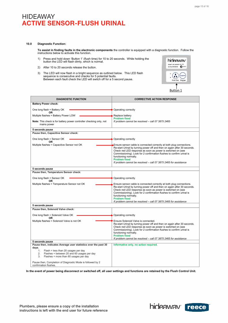
To assist in finding faults in the electronic components the controller is equipped with a diagnostic function. Follow the instructions below to activate this function.
1) Press and hold down ‘Button 1’ (flush time) for 10 to 20 seconds. While holding thebutton the LED will flash dimly, which is normal.
2) After 10 to 20 seconds release the button.
3) The LED will now flash in a bright sequence as outlined below. This LED flash sequence is consecutive and checks for 5 potential faults.Between each fault check the LED will switch off for a 5 second pause.
DIAGNOSTIC FUNCTION CORRECTIVE ACTION RESPONSE
Battery Power check:
One long flash = Battery OKOR
Multiple flashes = Battery Power LOW
Note: This check is for battery power controller checking only, not mains power
Operating correctly
Replace batteryProblem fixedIf problem cannot be resolved – call 07 3875 2465
5 seconds pausePause then, Capacitive Sensor check:
One long flash = Sensor OKOR
Multiple flashes = Capacitive Sensor not OK
Operating correctly
Ensure sensor cable is connected correctly at both plug connections.Re-start Urinal by turning power off and then on again after 30 seconds.Check red LED response as soon as power is switched on (see Commissioning). Look for 2 confirmation flushes to confirm urinal is functioning normally.Problem fixedIf problem cannot be resolved – call 07 3875 2465 for assistance
5 seconds pausePause then, Temperature Sensor check:
One long flash = Sensor OKOR
Multiple flashes = Temperature Sensor not OK
Operating correctly
Ensure sensor cable is connected correctly at both plug connections.Re-start Urinal by turning power off and then on again after 30 seconds.Check red LED response as soon as power is switched on (see Commissioning). Look for 2 confirmation flushes to confirm urinal is functioning normally.Problem fixedIf problem cannot be resolved – call 07 3875 2465 for assistance
5 seconds pausePause then, Solenoid Valve check:
One long flash = Solenoid Valve OKOR
Multiple flashes = Solenoid Valve is not OK
Operating correctly
Ensure Solenoid Valve is connected.Re-start Urinal by turning power off and then on again after 30 seconds.Check red LED response as soon as power is switched on (see Commissioning). Look for 2 confirmation flushes to confirm urinal is functioning normally.Problem fixedIf problem cannot be resolved – call 07 3875 2465 for assistance
5 seconds pausePause then, indicates Average user statistics over the past 30 days.
1. Flash = less than 20 usages per day2. Flashes = between 20 and 60 usages per day3. Flashes = more than 60 usages per day
Pause then, Completion of Diagnostic Mode is followed by 2 confirmation flushes.
Informative only, no action required.
In the event of power being disconnect or switched off, all user settings and functions are retained by the Flush Control Unit.
Button 1
page 13 of 16
HIDEAWAYACTIVE SENSOR-FLUSH URINAL
Plumbers, please ensure a copy of the installation instructions is left with the end user for future reference
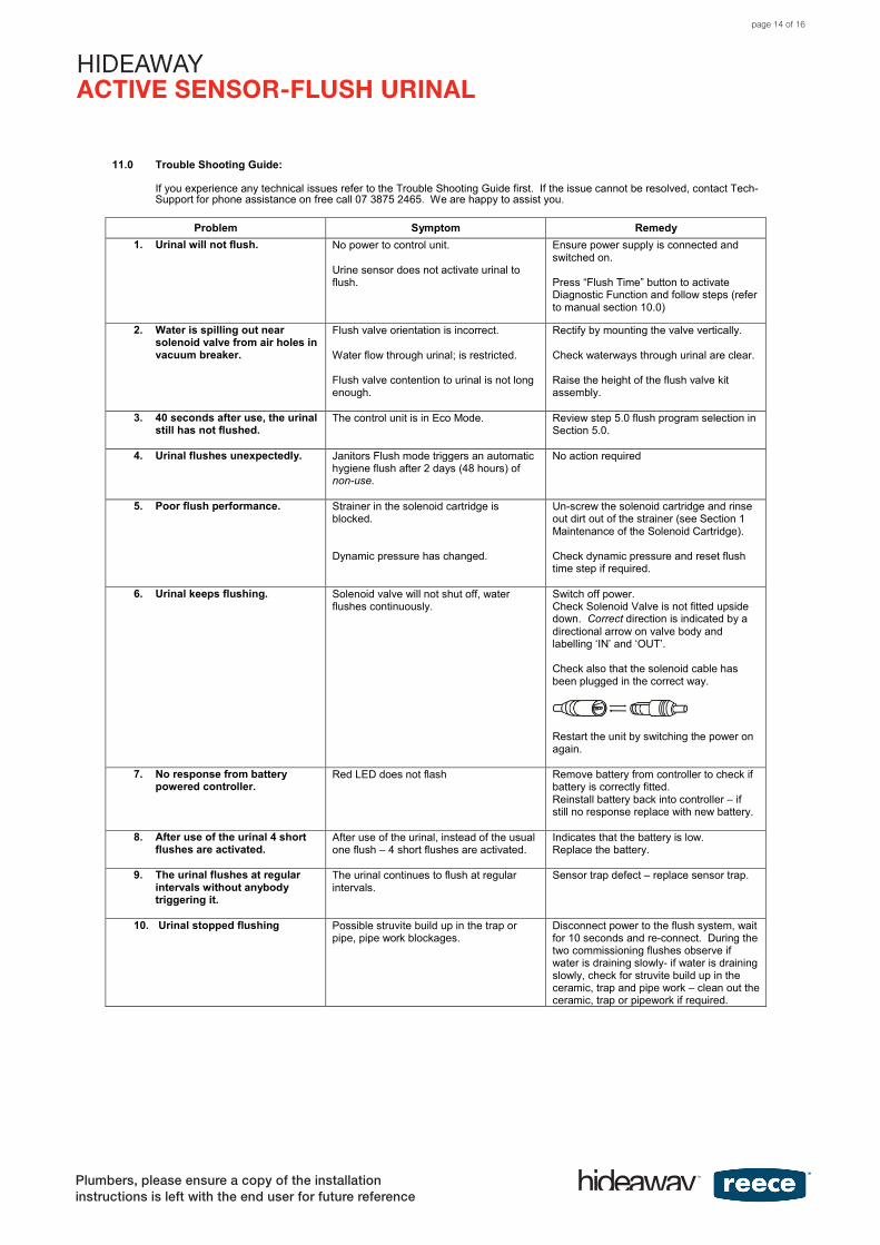
HIDEAWAYACTIVE SENSOR-FLUSH URINAL11.0 Trouble Shooting Guide:
If you experience any technical issues refer to the Trouble Shooting Guide first. If the issue cannot be resolved, contact Tech-Support for phone assistance on free call 07 3875 2465. We are happy to assist you.
Problem Symptom Remedy1. Urinal will not flush. No power to control unit.
Urine sensor does not activate urinal to flush.
Ensure power supply is connected and switched on.
Press “Flush Time” button to activate Diagnostic Function and follow steps (refer to manual section 10.0)
2. Water is spilling out nearsolenoid valve from air holes invacuum breaker.
Flush valve orientation is incorrect.
Water flow through urinal; is restricted.
Flush valve contention to urinal is not long enough.
Rectify by mounting the valve vertically.
Check waterways through urinal are clear.
Raise the height of the flush valve kit assembly.
3. 40 seconds after use, the urinalstill has not flushed.
The control unit is in Eco Mode. Review step 5.0 flush program selection in Section 5.0.
4. Urinal flushes unexpectedly. Janitors Flush mode triggers an automatic hygiene flush after 2 days (48 hours) of non-use.
No action required
5. Poor flush performance. Strainer in the solenoid cartridge is blocked.
Dynamic pressure has changed.
Un-screw the solenoid cartridge and rinse out dirt out of the strainer (see Section 1 Maintenance of the Solenoid Cartridge).
Check dynamic pressure and reset flush time step if required.
6. Urinal keeps flushing. Solenoid valve will not shut off, water flushes continuously.
Switch off power.Check Solenoid Valve is not fitted upside down. Correct direction is indicated by a directional arrow on valve body and labelling ‘IN’ and ‘OUT’.
Check also that the solenoid cable has been plugged in the correct way.
Restart the unit by switching the power on again.
7. No response from batterypowered controller.
Red LED does not flash Remove battery from controller to check if battery is correctly fitted.Reinstall battery back into controller – if still no response replace with new battery.
8. After use of the urinal 4 shortflushes are activated.
After use of the urinal, instead of the usual one flush – 4 short flushes are activated.
Indicates that the battery is low.Replace the battery.
9. The urinal flushes at regularintervals without anybodytriggering it.
The urinal continues to flush at regular intervals.
Sensor trap defect – replace sensor trap.
10. Urinal stopped flushing Possible struvite build up in the trap orpipe, pipe work blockages.
Disconnect power to the flush system, wait for 10 seconds and re-connect. During the two commissioning flushes observe if water is draining slowly- if water is draining slowly, check for struvite build up in the ceramic, trap and pipe work – clean out the ceramic, trap or pipework if required.
page 14 of 16
HIDEAWAYACTIVE SENSOR-FLUSH URINAL
Plumbers, please ensure a copy of the installation instructions is left with the end user for future reference
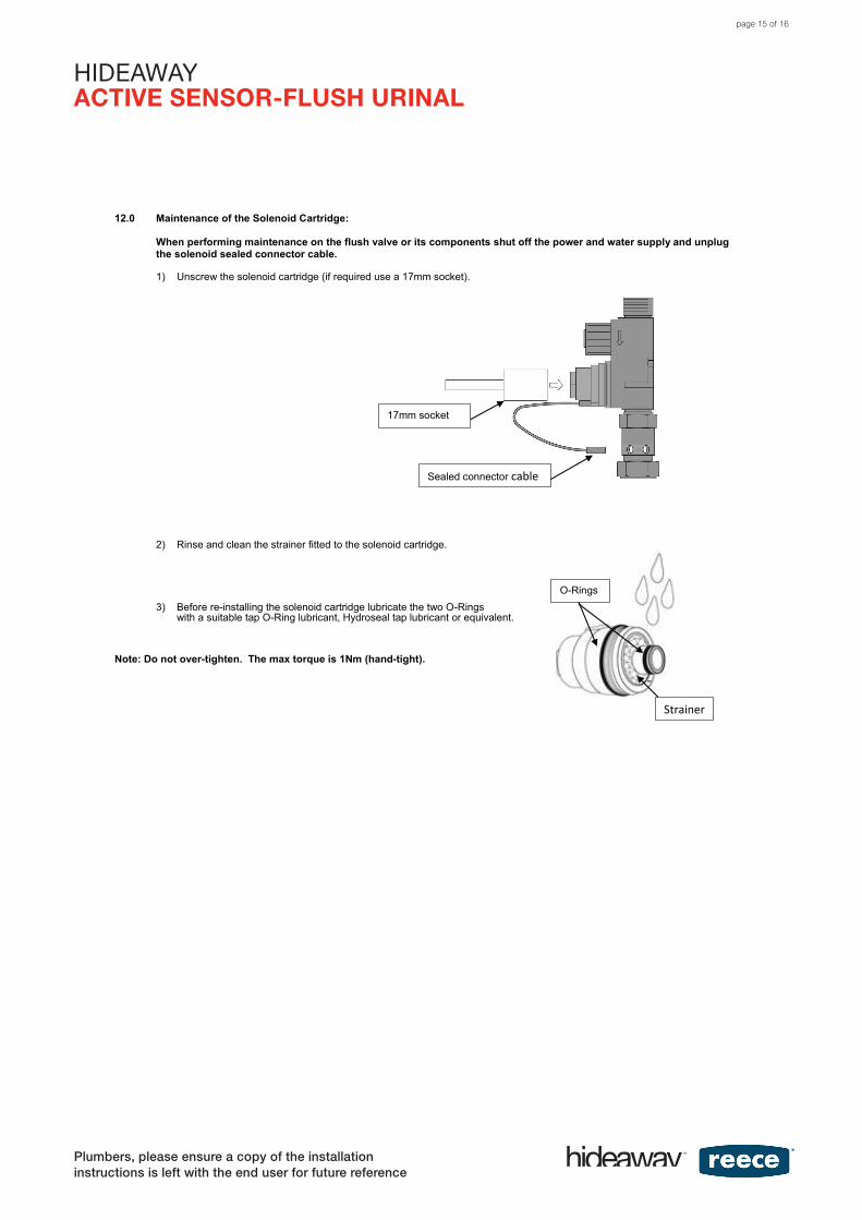
HIDEAWAY ACTIVE SENSOR-FLUSH URINAL 12.0 Maintenance of the Solenoid Cartridge:
When performing maintenance on the flush valve or its components shut off the power and water supply and unplug the solenoid sealed connector cable.
1) Unscrew the solenoid cartridge (if required use a 17mm socket).
2) Rinse and clean the strainer fitted to the solenoid cartridge.
3) Before re-installing the solenoid cartridge lubricate the two O-Rings with a suitable tap O-Ring lubricant, Hydroseal tap lubricant or equivalent.
Note: Do not over-tighten. The max torque is 1Nm (hand-tight). 13.0 Spare parts
9503303 HIDEAWAY URINAL CONTROL UNIT 240V 9503304 HIDEAWAY URINAL SENSOR TRAP (NO SEALS) 9503305 HIDEAWAY URINAL 240V TRANSFORMER 9503306 HIDEAWAY URINAL SENSOR EXT CABLE (2.65M) 9503307 HIDEAWAY URINAL INLET & OUTLET SEAL 9503308 HIDEAWAY URINAL SHUTOFF VALVE 9503309 HIDEAWAY URINAL SOLENOID CARTRIDGE 9503310 HIDEAWAY URINAL SOLENOID BODY 9503311 HIDEAWAY URINAL AIR-BREAK 9503984 HIDEAWAY URINAL CONTROL BATTERY POW ERED (LESS BATTERY) 9503985 HIDEAWAY URINAL BATTERY 6V CR-P2
17mm socket
Sealed connector cable
O-Rings
Strainer
page 15 of 16
HIDEAWAYACTIVE SENSOR-FLUSH URINAL
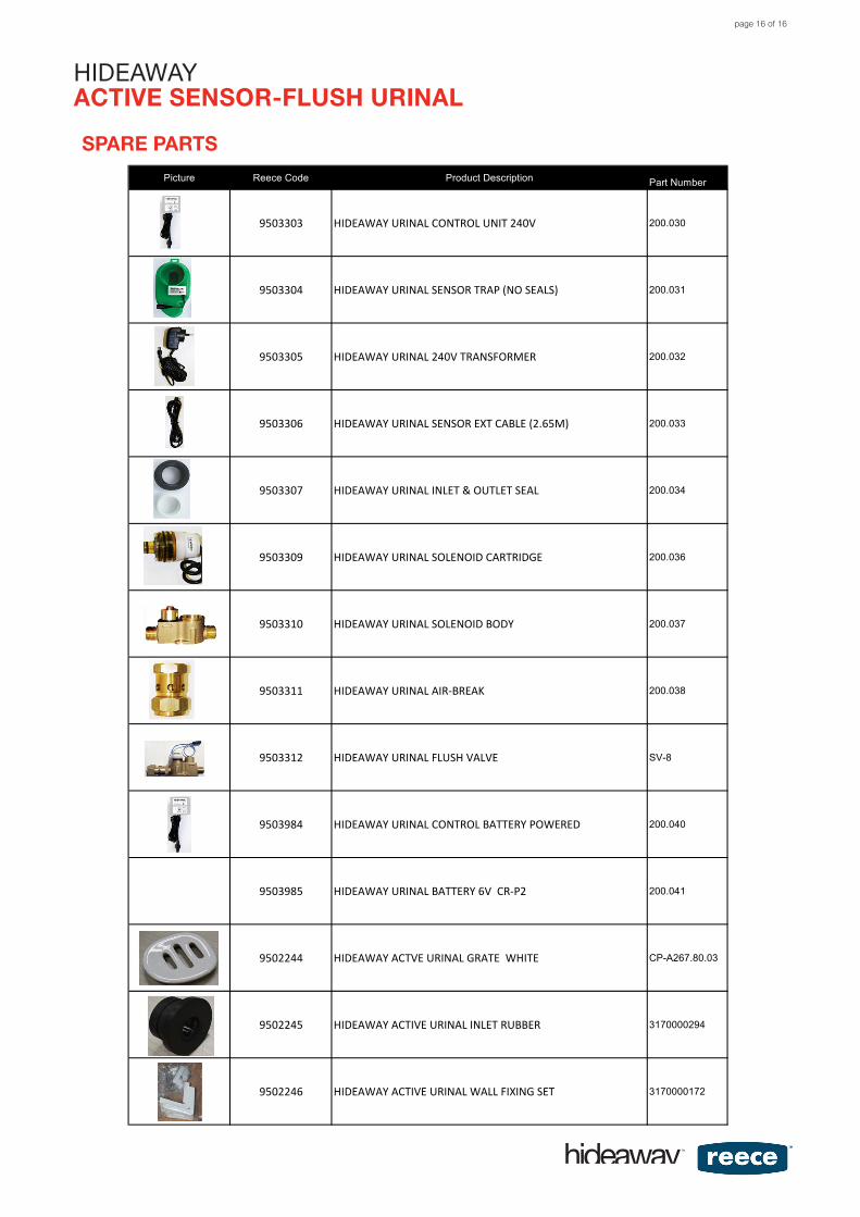
Picture Reece Code Product Description Part Number
9503303 HIDEAWAY URINAL CONTROL UNIT 240V 200.030
9503304 HIDEAWAY URINAL SENSOR TRAP (NO SEALS) 200.031
9503305 HIDEAWAY URINAL 240V TRANSFORMER 200.032
9503306 HIDEAWAY URINAL SENSOR EXT CABLE (2.65M) 200.033
9503307 HIDEAWAY URINAL INLET & OUTLET SEAL 200.034
9503309 HIDEAWAY URINAL SOLENOID CARTRIDGE 200.036
9503310 HIDEAWAY URINAL SOLENOID BODY 200.037
9503311 HIDEAWAY URINAL AIR‐BREAK 200.038
9503312 HIDEAWAY URINAL FLUSH VALVE SV-8
9503984 HIDEAWAY URINAL CONTROL BATTERY POWERED 200.040
9503985 HIDEAWAY URINAL BATTERY 6V CR‐P2 200.041
9502244 HIDEAWAY ACTVE URINAL GRATE WHITE CP-A267.80.03
9502245 HIDEAWAY ACTIVE URINAL INLET RUBBER 3170000294
9502246 HIDEAWAY ACTIVE URINAL WALL FIXING SET 3170000172
SPARE PARTS
page 16 of 16