Embed Size (px)
Citation preview
2
Agenda
In Salah CCS: Project Description
Site Selection and Management
Monitoring Stored CO2: Joint Industry Project
Key Lessons Learned from Phase 1
–Well Integrity: KB-5
–Seismic Interpretation
Plans for Phase 2
Questions/Answers
3
Krechba
Teg
Reg
Garet elBefinat Hassi Moumene
In Salah
Gour Mahmoud
Proposed ISG Pipeline
REB
Hassi BirRekaiz
Hassi Messaoud
Hassi R’Mel
Tiguentourine (BP)
02151093
Algiers
Tangiers
Lisbon
Cordoba
Cartagena
M O R O C C O
A L G E R I A
S P A I N
L I B Y A
MAURITANIAM A L I
SkikdaTunis
N I G E R
In Salah Gas Project
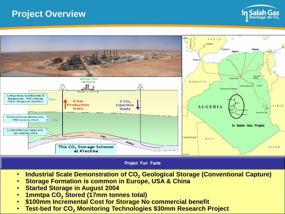
• Industrial Scale Demonstration of CO2 Geological Storage (Conventional Capture)• Storage Formation is common in Europe, USA & China• Started Storage in August 2004• 1mmtpa CO2 Stored (17mm tonnes total)• $100mm Incremental Cost for Storage No commercial benefit• Test-bed for CO2 Monitoring Technologies $30mm Research Project
Project Fun Facts
Project Overview
4
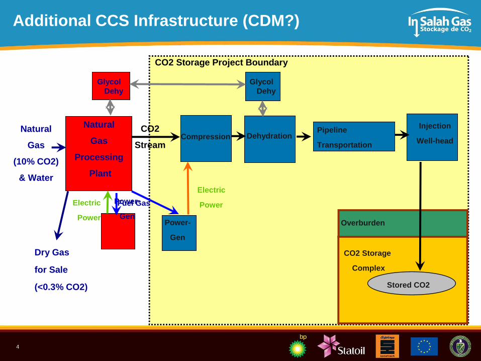
Additional CCS Infrastructure (CDM?)
Natural
Gas
(10% CO2)
& Water
Power-
GenPower-
Gen
Compression DehydrationPipeline
Transportation
Injection
Well-head
Dry Gas
for Sale
(<0.3% CO2)
Natural
Gas
Processing
Plant
CO2
Stream
Fuel Gas
Electric
PowerElectric
PowerOverburden
Stored CO2
CO2 Storage
Complex
CO2 Storage Project Boundary
Glycol
Dehy
Glycol
Dehy
5
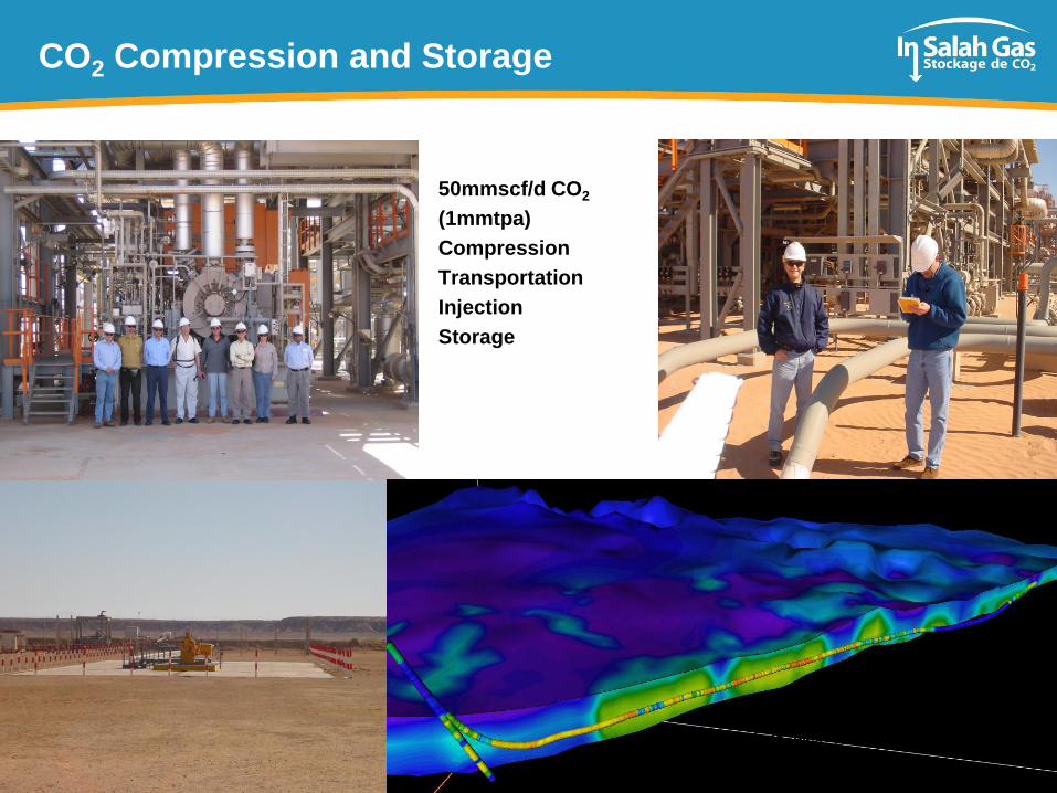
CO2 Compression and Storage
50mmscf/d CO2
(1mmtpa)
Compression
Transportation
Injection
Storage
Krechba 501
Pilot hole plus 1250 metres of horizontal section
6
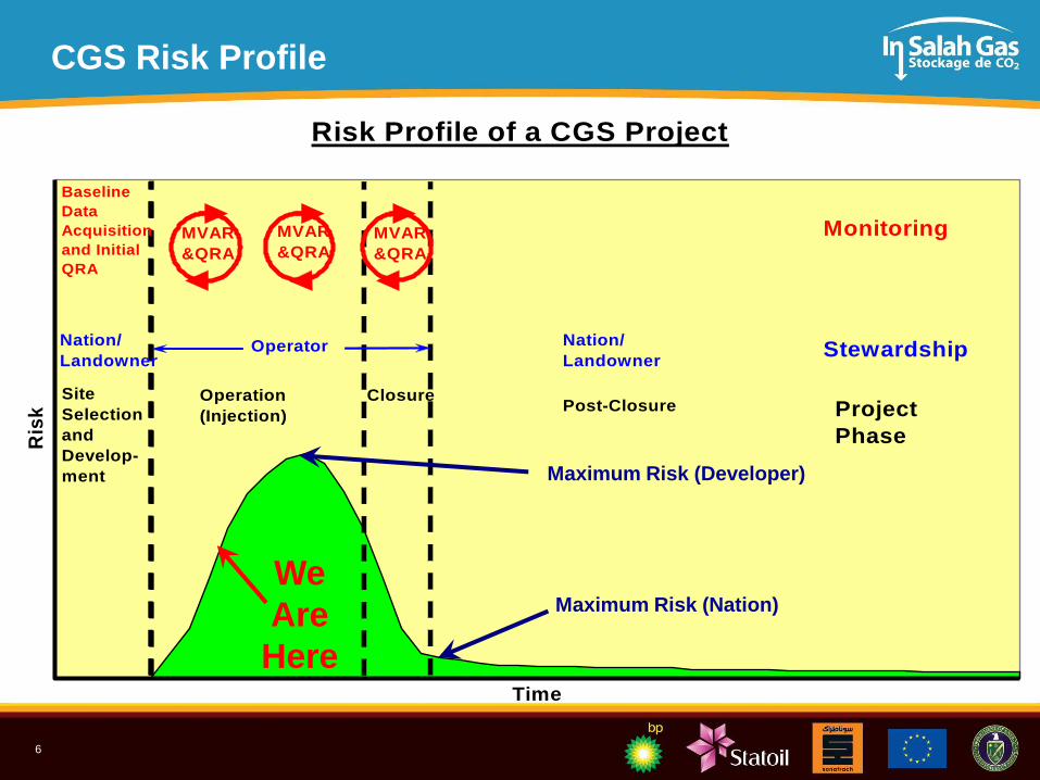
CGS Risk Profile
Risk Profile of a CGS Project
Time
Ris
k
Site
Selection
and
Develop-
ment
Operation
(Injection)
ClosurePost-Closure
MVAR
&QRA
Nation/
Landowner
Nation/
LandownerOperator Stewardship
Project
Phase
Monitoring
Baseline
Data
Acquisition
and Initial
QRA
MVAR
&QRA
MVAR
&QRA
We
Are
Here
Maximum Risk (Developer)
Maximum Risk (Nation)
7
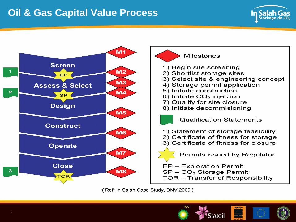
Oil & Gas Capital Value Process
( Ref: In Salah Case Study, DNV 2009 )( Ref: In Salah Case Study, DNV 2009 )
8
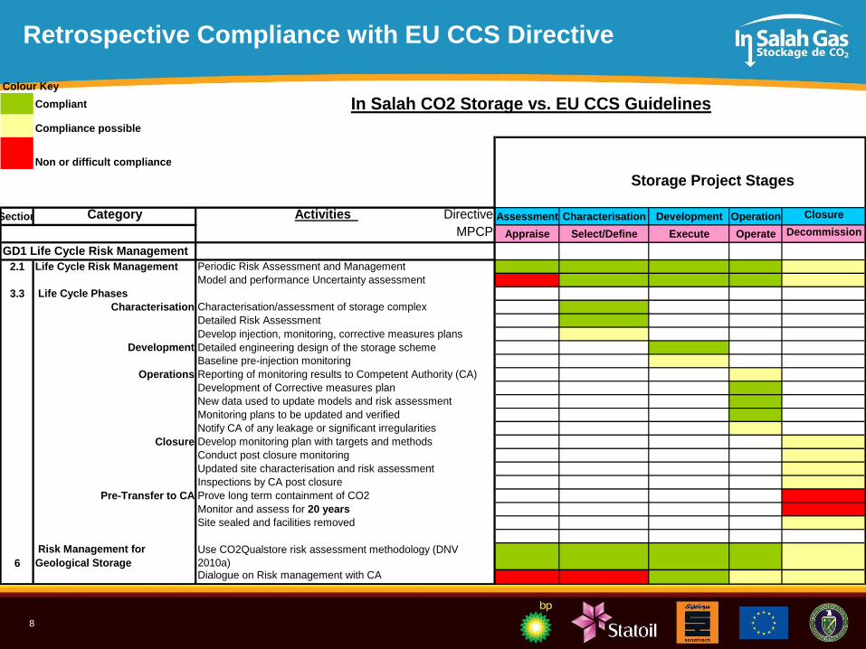
Retrospective Compliance with EU CCS Directive
Colour Key
Compliant
Compliance possible
Non or difficult compliance
Section Category Activities Directive Assessment Characterisation Development Operation Closure
MPCP Appraise Select/Define Execute Operate Decommission
2.1 Life Cycle Risk Management Periodic Risk Assessment and Management
Model and performance Uncertainty assessment
3.3 Life Cycle Phases
Characterisation Characterisation/assessment of storage complex
Detailed Risk Assessment
Develop injection, monitoring, corrective measures plans
Development Detailed engineering design of the storage scheme
Baseline pre-injection monitoring
Operations Reporting of monitoring results to Competent Authority (CA)
Development of Corrective measures plan
New data used to update models and risk assessment
Monitoring plans to be updated and verified
Notify CA of any leakage or significant irregularities
Closure Develop monitoring plan with targets and methods
Conduct post closure monitoring
Updated site characterisation and risk assessment
Inspections by CA post closure
Pre-Transfer to CA Prove long term containment of CO2
Monitor and assess for 20 years
Site sealed and facilities removed
6
Risk Management for
Geological Storage
Use CO2Qualstore risk assessment methodology (DNV
2010a)Dialogue on Risk management with CA
In Salah CO2 Storage vs. EU CCS Guidelines
Storage Project Stages
GD1 Life Cycle Risk Management
9
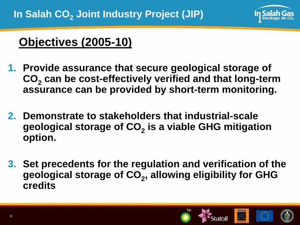
In Salah CO2 Joint Industry Project (JIP)
1. Provide assurance that secure geological storage of CO2 can be cost-effectively verified and that long-term assurance can be provided by short-term monitoring.
2. Demonstrate to stakeholders that industrial-scale geological storage of CO2 is a viable GHG mitigation option.
3. Set precedents for the regulation and verification of the geological storage of CO2, allowing eligibility for GHG credits
Objectives (2005-10)
10
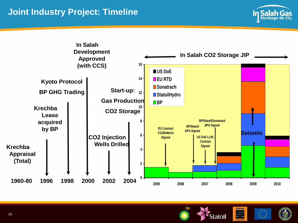
Joint Industry Project: Timeline
0
2
4
6
8
10
12
14
16
2005 2006 2007 2008 2009 2010
US DoE
EU RTD
Sonatrach
StatoilHydro
BP
EU Contract
CO2ReMoVe
Signed
BP/Statoil
JIPA Signed
BP/Statoil/Sonatrach
JIPA Signed
US DoE LLNL
Contract
Signed
1960-80 1996 1998 2000 2002 2004
Krechba
Appraisal
(Total)
Krechba
Lease
acquired
by BP
Kyoto Protocol
BP GHG Trading
In Salah
Development
Approved
(with CCS)
CO2 Injection
Wells Drilled
Start-up:
Gas Production
CO2 Storage
In Salah CO2 Storage JIP
Seismic
11
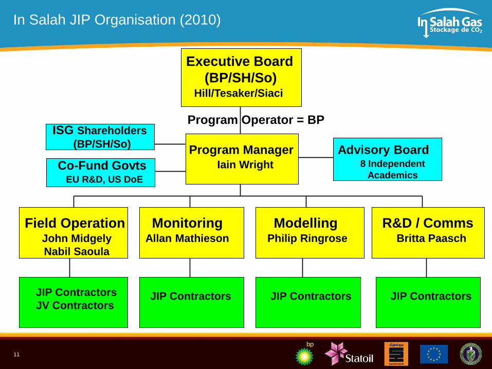
In Salah JIP Organisation (2010)
Executive Board
(BP/SH/So)Hill/Tesaker/Siaci
Program ManagerIain Wright
ModellingPhilip Ringrose
R&D / CommsBritta Paasch
MonitoringAllan Mathieson
Co-Fund GovtsEU R&D, US DoE
JIP Contractors JIP Contractors JIP Contractors
Advisory Board8 Independent
Academics
Program Operator = BPISG Shareholders
(BP/SH/So)
Field OperationJohn Midgely
Nabil Saoula
JIP Contractors
JV Contractors
12
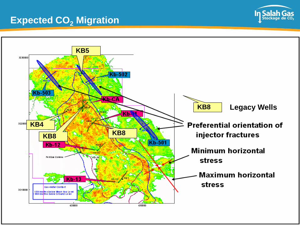
Expected CO2 Migration
KB5
KB4
KB8KB8
KB8 Legacy Wells
13
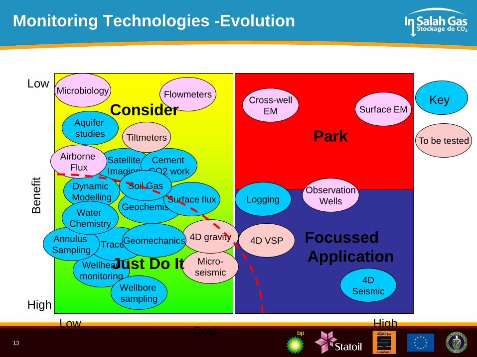
Benefit
CostLow High
Low
High
Satellite
Imaging
Geochemistry
Micro-
seismic
Flowmeters
Wellhead
monitoring
4D gravityTracers
Dynamic
Modelling
Wellbore
sampling
Annulus
Sampling4D VSP
Cement
CO2 work
4D
Seismic
Tiltmeters
Cross-well
EM
Geomechanics
Logging
Surface EM
Aquifer
studies
Microbiology
Surface fluxObservation
Wells
Airborne
Flux
Park
Focussed
ApplicationJust Do It
Consider Key
To be tested
Water
Chemistry
Monitoring Technologies -Evolution
Soil Gas
14
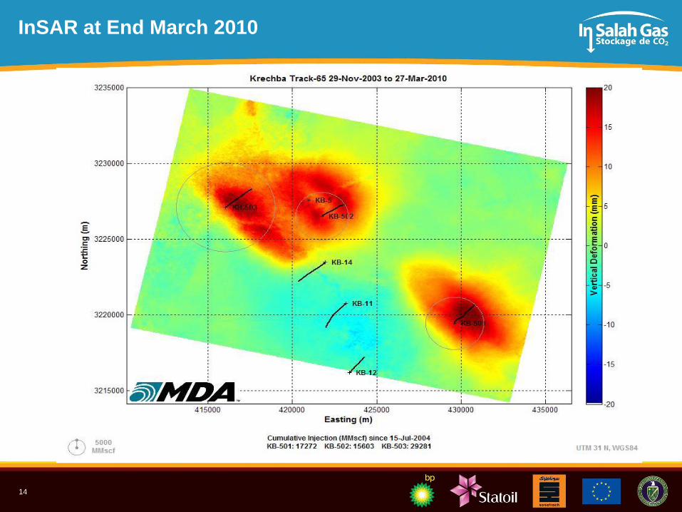
InSAR at End March 2010
15
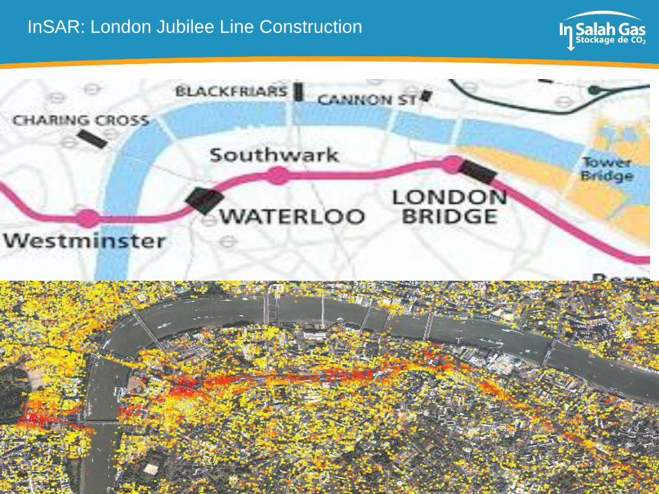
InSAR: London Jubilee Line Construction
16
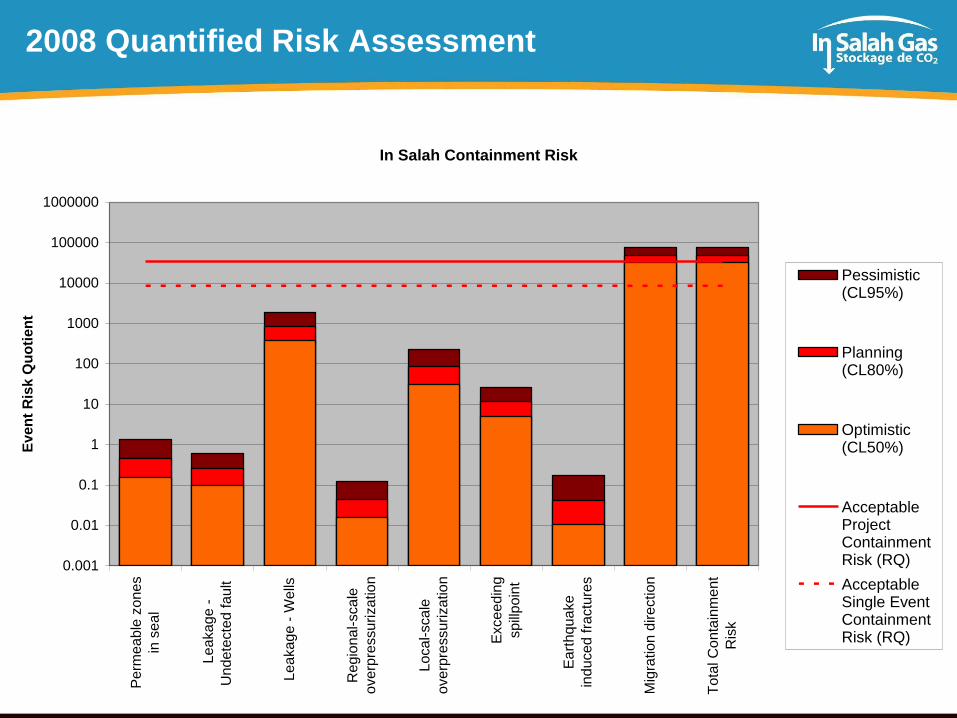
2008 Quantified Risk Assessment
In Salah Containment Risk
0.001
0.01
0.1
1
10
100
1000
10000
100000
1000000
Pe
rme
ab
le z
on
es
in s
ea
l
Lea
kag
e -
Un
de
tecte
d f
ault
Lea
kag
e -
We
lls
Re
gio
na
l-sca
le
overp
ressu
rizatio
n
Loca
l-sca
le
overp
ressu
rizatio
n
Exce
ed
ing
sp
illp
oin
t
Ea
rth
qu
ake
indu
ced
fra
ctu
res
Mig
ratio
n d
ire
ction
Tota
l C
onta
inm
en
t
Ris
k
Ev
en
t R
isk Q
uo
tie
nt
Pessimistic(CL95%)
Planning(CL80%)
Optimistic(CL50%)
AcceptableProjectContainmentRisk (RQ)
AcceptableSingle EventContainmentRisk (RQ)
17
Focus on Two Topics
1. Well Integrity: KB-5
2. Seismic Interpretation
18
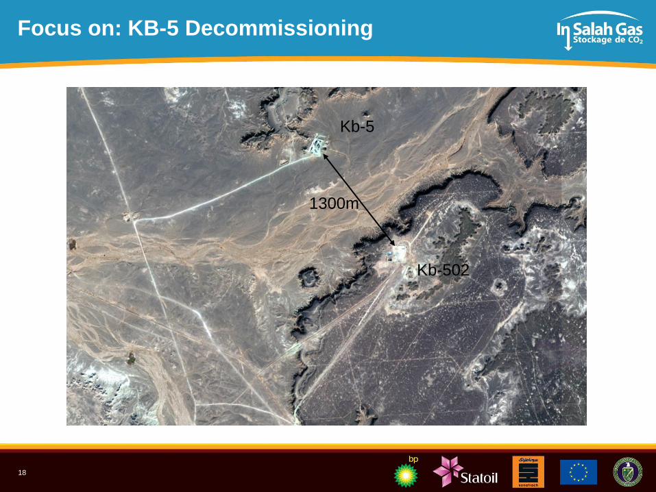
Focus on: KB-5 Decommissioning
Kb-5
Kb-502
1300m
19
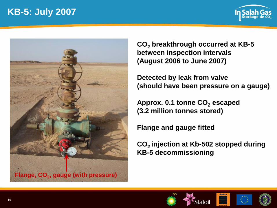
KB-5: July 2007
CO2 breakthrough occurred at KB-5
between inspection intervals
(August 2006 to June 2007)
Detected by leak from valve
(should have been pressure on a gauge)
Approx. 0.1 tonne CO2 escaped
(3.2 million tonnes stored)
Flange and gauge fitted
CO2 injection at Kb-502 stopped during
KB-5 decommissioning
Flange, CO2, gauge (with pressure)
20
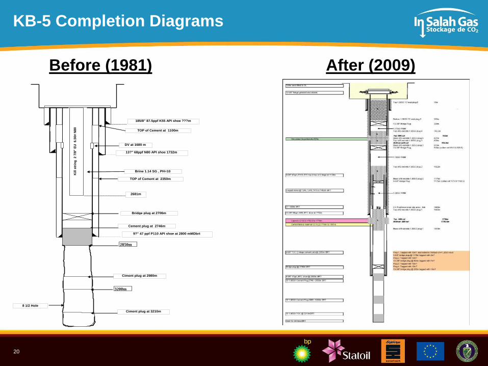
KB-5 Completion DiagramsRig Name: Super20
Start date: 11/01/1980
Suspension date: 18/08/1980
Well Data:
Hole Size Depths (mDDbrt)
26 ???
17 1/2 1732
12 1/4" 2800
8 1/2 3415
Casings Depths (mDDbrt) `
18 5/8 150
13 3/8" 1732
9 5/8" 2800
LOT or FIT EMW (SG)
Reservoir Sections
Kb-5
Well Schematic
13?" 68ppf N80 API shoe 1732m
9?" 47 ppf P110 API shoe at 2800 mMDbrt
8 1/2 Hole
Ciment plug at 3210m
Note : All depths referenced to
Super20 RTE = 5.4mAGL
Cement plug at 2746m
Kil
l s
trin
g
2 7
/8"
EU
6
.50#
N8
0
2681m
Brine 1.14 SG , PH=10
185/8" 87.5ppf K55 API shoe ???m
Ciment plug at 2980m
2850m
3200m
Bridge plug at 2706m
DV at 1680 m
TOP of Cement at 2350m
TOP of Cement at 1100m
Before (1981) After (2009)
21
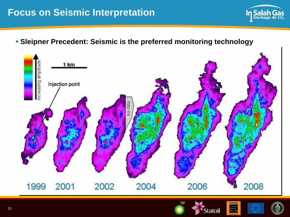
Focus on Seismic Interpretation
Sleipner Precedent: Seismic is the preferred monitoring technology
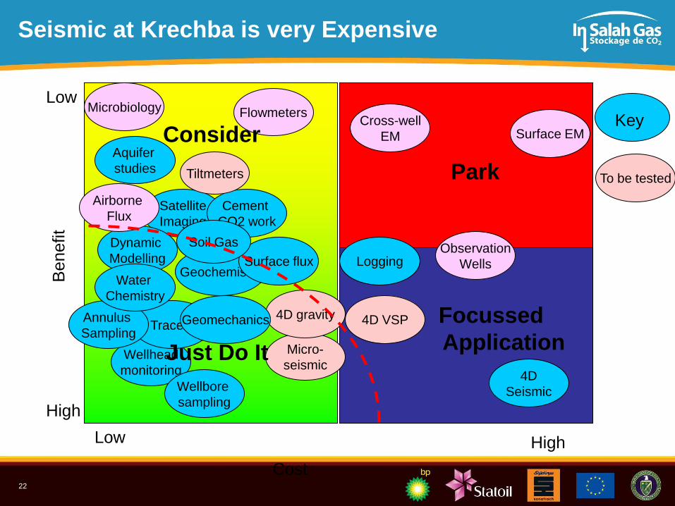
22
Cost
Low High
Seismic at Krechba is very ExpensiveB
enefit
Low
High
Satellite
Imaging
Geochemistry
Micro-
seismic
Flowmeters
Wellhead
monitoring
4D gravityTracers
Dynamic
Modelling
Wellbore
sampling
Annulus
Sampling4D VSP
Cement
CO2 work
4D
Seismic
Tiltmeters
Cross-well
EM
Geomechanics
Logging
Surface EM
Aquifer
studies
Microbiology
Surface fluxObservation
Wells
Airborne
Flux
Park
Focussed
ApplicationJust Do It
Consider Key
To be tested
Water
Chemistry
Soil Gas
23
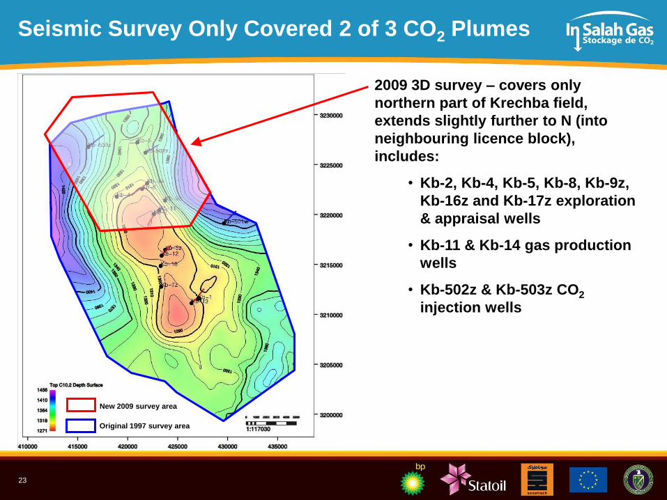
Seismic Survey Only Covered 2 of 3 CO2 Plumes
2009 3D survey – covers only
northern part of Krechba field,
extends slightly further to N (into
neighbouring licence block),
includes:
• Kb-2, Kb-4, Kb-5, Kb-8, Kb-9z,
Kb-16z and Kb-17z exploration
& appraisal wells
• Kb-11 & Kb-14 gas production
wells
• Kb-502z & Kb-503z CO2
injection wells
Original 1997 survey area
New 2009 survey area
24
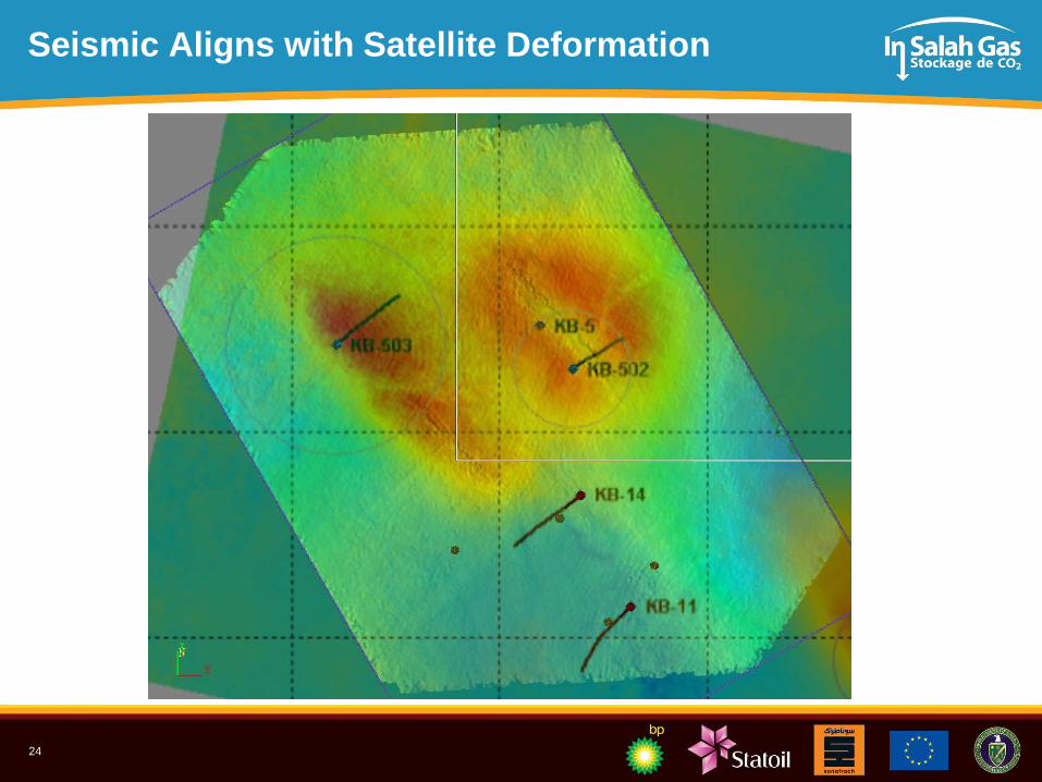
Seismic Aligns with Satellite Deformation
25
In Salah CCS: Conclusions
Pioneering (Industrial-Scale) CCS project:
– Successful CO2 storage: > 5years, > 3mm tonnes stored, 19 GHGT10 Papers
Excellent collaboration: IOC/NOC/Government/Academia
Injection operations very much as anticipated
Site selection and management is more important than monitoring
Monitoring programmes will be very site-specific:
– InSAR (Satellite) and Wellhead data are very cost-effective
– Seismic very useful, but complex and expensive
CO2 plume/pressure is not homogenous
– Needs high resolution data for appropriate characterisation
– Have modified the storage operation based on lessons learned
26
What Next?
Phase 1: 2006-2010
In Salah is a “data-rich”
project in a “data-poor”
environment
Phase 2: 2011-2015
–LLNL, LBNL
27
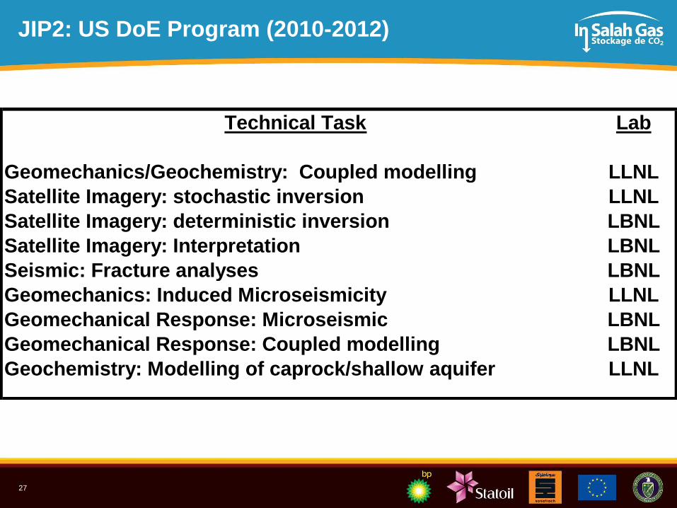
JIP2: US DoE Program (2010-2012)
Technical Task Lab
Geomechanics/Geochemistry: Coupled modelling LLNL
Satellite Imagery: stochastic inversion LLNL
Satellite Imagery: deterministic inversion LBNL
Satellite Imagery: Interpretation LBNL
Seismic: Fracture analyses LBNL
Geomechanics: Induced Microseismicity LLNL
Geomechanical Response: Microseismic LBNL
Geomechanical Response: Coupled modelling LBNL
Geochemistry: Modelling of caprock/shallow aquifer LLNL
28
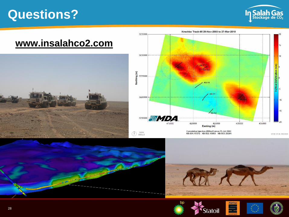
Questions?
www.insalahco2.com