Embed Size (px)
Citation preview

July / Aug 2014 Issue 40
Demonstrating CCS capture from industrial sources in the UK
CCS in the Netherlands and the future of ROAD
Optimising CFB technology with CO2 capture at CIUDEN
Lafarge’s new process for CO2 mineralisation
Carbon storage potential in Wyoming and Montana
CCS in AustraliaCarbonNet full-chain CCShub project
Updates from Otway andCallide projects
Funding for the CCSFlagships Program
CCJ40_Layout 1 29/06/2014 15:29 Page 1
www.tcmda.com
CO2 Technology Centre Mongstad in Norwaycontributes to a series of advancements inreducing the cost and the technical,environmental and financial risks ofimplementing CO2 capture technology.
The two technology demonstrations of Akerand Alstom have been overlaid onto TCM's coreutility infrastructure; which provides access to100,000 tonnes per year of gas-fired andsimulated coal CO2 flue gases.
At present we are also running a MEA test, andthe results will provide base line performancecriteria for technology vendors to establish acomplete benchmark and reference point forcomparison to future amine plant users.
TCM is the world’s largest and most advancedfacility for testing and improving CO2 capture,and is a joint venture set up by the Norwegianstate (75.12 %), Statoil (20 %), Shell (2.44 %)and Sasol (2.44 %).
Read more at www.tcmda.com
CATCHING OUR FUTURE
CCJ40_Layout 1 29/06/2014 15:30 Page 2

Contents
Demonstrating CO2 capture from industrial sectors in the UKA team led by Element Energy looked at the technical potential and cost effectivenessfor retrofit deployment of different CO2 capture technologies to the UK’s existing largestsources of process CO2 emissions by 2025
Alberta continues to support CCSThe Province of Alberta, Canada is continuing to invest in two carbon capture andstorage projects: the Alberta Carbon Trunk Line and Quest Project
CCS in the Netherlands - and the future of ROADROAD, the Dutch flagship CCS project, is currently “essentially mothballed” while theproject team wait for financing. Speakers at the CATO conference discussed who shouldbe doing more to get it moving – industry or government?
MPs urge the Government to ‘fast-track’ CCSMPs in the UK have urged the Government to fast-track final funding decisions on twopilot Carbon capture and storage projects at Peterhead and Drax by early 2015
DOE recovery act project begins The project at Tampa Electric Company’s Polk Power Plant in Florida will demonstratewarm syngas desulfurization and CO2 capture
Carbon Capture JournalUnited House, North Road, London N7 9DPwww.carboncapturejournal.comTel +44 (0)207 017 3405Fax +44 (0)207 251 9179
EditorKeith [email protected]
PublisherKarl [email protected]
Advertising and SponsorshipJohn FinderTel +44 (0)208 874 [email protected]
Optimisation of oxygen-based CFB technology with CO2 capture at CIUDENCIUDEN is working on the FP7 European O2GEN project, which focuses on one of themost important recommendations of the Zero Emission Platform´s report for thedeployment of CCS in the European Union: the use of higher O2 concentrations inoxyfuel combustion reducing the flue gas recirculation and energy penalty
Lafarge’s new process for CO2 mineralizationLafarge has developed a novel atmospheric-pressure process for the capture of CO2from flue gases, using conventional industrial equipment and avoiding the energy-intensive CO2 purification and compression steps typical of current CCS approaches
CarbonNet full-chain CCS project advances Australia’s CarbonNet Project is well advanced in its investigation into the feasibility of acommercial-scale, multi-user CCS hub in the state of Victoria’s Gippsland region
Latest CO2CRC Otway project newsThe CO2CRC Otway Project has been an important research facility for work on geologicalstorage, from its initial stage of demonstrating safe storage of CO2 in a depleted gas field,to more recent experiments leading to improved assessment of storage efficiency
Callide oxyfuel project updateThe $245 million Callide Oxyfuel Project in Central Queensland continues to lead the wayin the demonstration and development of low emission coal-fired electricity generation,passing more than 6,000 hours of operation
Australia’s CCS Flagships ProgramDennis Van Puyvelde of Van Puyvelde Energy and CCS Research Consultants takes a look athow the recent Australian Budget affects funding for its CCS Flagships Program
Capture and utilisation
Leaders
Carbon capture journal (Print) ISSN 1757-1995
Carbon capture journal (Online) ISSN 1757-2509July - Aug 2014 - carbon capture journal
Carbon Capture Journal is your one stopinformation source for new technicaldevelopments, opinion, regulatory andresearch activity with carbon capture,transport and storage.
Carbon Capture Journal is delivered on printand pdf version to a total of 6000 people, allof whom have requested to receive it,including employees of power companies,oil and gas companies, government,engineering companies, consultants,educators, students, and suppliers.
Subscriptions: £250 a year for 6 issues. Tosubscribe, please contact Karl Jeffery [email protected] you can subscribe online at www.d-e-j.com/store
7
July / Aug 2014 Issue 40
1
16
9
Projects and policy
2
12
28
Transport and storage
Carbon storage potential in WyomingA geological feature in Wyoming could store up to 300 years of the region's CO2emissions, a study finds
Big Sky Carbon Sequestration Partnership drilling progressThe BSCSP field team has made substantial progress on the monitoring well sincedrilling began in May
11
27
19
8
22
5
Front cover: The CRC-1wellhead at theOtway carbondioxide storagedemonstrationproject inVictoria,Australia -multipleinjection andmonitoringwells meansthe OtwayProject is wellplaced forfuturecollaborations
17
CCJ40_Layout 1 29/06/2014 15:30 Page 1

carbon capture journal - July - Aug 20142
Leaders - CCS in Australia
T 02 A i k l d h d (RG G ) 297 210 i dd 1 2014 01 27 11 59 29
CarbonNet emerged out of a number of Aus-
tralian and Victorian government initiatives,
culminating in early 2012 with the project
being awarded Australian Government CCS
Flagship status along with $100 million in
joint Australian and Victorian government
funding to continue with detailed feasibility
studies.
The project’s multi-disciplined team
has led a range of detailed studies investigat-
ing the whole CCS chain, including capture
and pipeline options, commercial, environ-
ment, regulatory, planning, and social issues,
and the geological assessment of storage
sites in the Gippsland Basin.
The project anticipates the feasibility
studies (including securing rights to its pre-
ferred offshore storage sites) will be con-
cluded next year. This will inform a business
case to support a decision to undertake field
activities to assess the preferred storage site,
such as seismic surveys and drilling.
Storage site selection and DNVcertificationCarbonNet’s storage investigation pro-
gramme built on earlier work by the Aus-
tralian Government’s Carbon Storage Task-
force, which identified the offshore Gipps-
land Basin as “Australia’s most suitable stor-
age basin”*, and the Victorian Government’s
geological research, which identified the
near shore zone as presenting the best oppor-
tunities for storage in the short to medium
term.
CarbonNet’s team of geoscientists,
modellers and reservoir engineers, support-
ed by industry consultants, drew on a wealth
of existing data from the oil and gas indus-
try which has operated in the region for over
50 years, to identify sites with the potential
for secure CO2 storage.
Initially, 14 storage site options were
identified, each comprising two possible
storage intervals (sections of the geological
stratigraphy that is suitable for carbon diox-
ide (CO2) injection, with a sealing layer of
cap rock). An extensive and methodical as-
sessment and ranking process led to three
offshore sites being identified for further
analysis, with one prioritised for field inves-
tigation. The prioritised site has the capacity
to store up to 125 million tonnes of CO2 in
the main storage interval, with additional un-
quantified potential in other intervals.
CarbonNet’s storage site analysis and
assessment follows a robust process consis-
tent with international best practice. The pro-
ject’s evaluation process and findings have
been subjected to four international review
processes involving experts and scientific
peers. In addition, in November 2012, the
project engaged global quality control and
risk management services provider Det
Norske Veritas (DNV) to assess its storage
site selection process with reference to
DNV’s recommended practice (DNV-RP-
J203). CarbonNet obtained the first stage of
DNV certification for the portfolio of three
offshore sites in January 2013.
The project is currently seeking DNV
verification for its appraisal plan, which out-
lines a range of potential field activities to
acquire additional data for conformance with
recommended practice, secure the necessary
regulatory approvals, and to confirm Car-
bonNet’s geological modelling of the priori-
tised offshore storage site. This process in-
cluded a two day intensive workshop involv-
ing the CarbonNet team, its advisor Schlum-
berger Carbon Services, and a DNV panel of
five technical specialists in key areas of geo-
science and storage integrity, who meticu-
lously scrutinised the proposed appraisal
plan.
Assessing technical feasibility – CO2capture and transportSupported by a range of professional consul-
tancies including Parsons Brinckerhoff,
GHD and AECOM, CarbonNet has under-
taken a number of technical studies focused
on CO2 capture and transport, including the
related environment and planning aspects.
A whole of project basis-of-design has
been prepared, which links together all ele-
ments of the CCS chain. The basis of design
defines key parameters such as the CO2
specification which would represent the in-
terface between industry and the CarbonNet
network.
In a process similar to the project’s
CarbonNet full-chain CCS project advancesAustralia’s CarbonNet Project is well advanced in its investigation into the feasibility of a commercial-scale, multi-user CCS hub in the state of Victoria’s Gippsland region.By the Department of State Development, Business and Innovation, Government of Victoria
CarbonNet has shortlisted three potential offshore storage sites out of an initial 14 options, withone prioritised for field investigation
CCJ40_Layout 1 29/06/2014 15:31 Page 2

Marine Engines & Systems Power Plants Turbomachinery After Sales
T 02 A i k l d h d (RG G ) 297 210 i dd 1 2014 01 27 11 59 29
CCJ40_Layout 1 29/06/2014 15:31 Page 3

to progress to subsequent stages following
the successful completion of the current
stage. The business case will provide recom-
mendations on a pathway forward, including
field activities to assess the preferred stor-
age site.
Following government’s consideration
of the business case, appraisal of the pre-
ferred storage site will commence, drawing
on current existing and committed funding.
Each major field activity conducted as part
of appraisal will require regulatory ap-
provals, and will involve extensive stake-
holder consultation. Engaging communities
will be a key focus as the project progresses
with on-the-ground and planning activities.
CarbonNet looks forward to presenting
on the project’s achievements and status to a
broad range of national and international
stakeholders at Australia’s National CCS
Conference in August-September this year.
*Carbon Storage Taskforce 2009
which is adjacent to the offshore Gippsland
Basin, which has been assessed as having the
greatest capacity for CO2 storage of any
basin along Australia’s eastern seaboard.
The offshore Gippsland was ranked as the
highest technically and it also has the lowest
transport and storage cost per tonne of CO2
avoided*.
This presents significant opportunities
for companies interested in capitalising on
the coal resource, including generators, coal-
to-products and other industries. CarbonNet
has undertaken an extensive national and in-
ternational industry engagement process and
received strong support from a wide cross
section of industry, with many emphasising
the importance of CCS as an enabler for in-
vestment.
A framework for developing a business
model for a network-based CCS project has
been prepared by CarbonNet’s commercial
team and advisers. The commercial frame-
work provides a structured approach for
comparing alternative commercial and finan-
cial arrangements for a hub project with pub-
lic and private participants.
This framework was presented at Vic-
toria’s Low Rank Coal Symposium 2014 and
will form part of an upcoming knowledge
sharing report supported by the Global CCS
Institute.
What next?CarbonNet takes a stage gated approach to
development of the project. This means gov-
ernment will make key decisions on whether
storage site assessment, potential pipeline
corridors from the Latrobe Valley – where
the region’s vast brown coal resources are
located – to the offshore storage site approx-
imately 130 kilometres away, have been as-
sessed and prioritised.
A transport economics model has also
been constructed to allow scenarios to be
tested for infrastructure capacity sizing and
staging. This will allow decisions on the op-
timal size and timing of pipelines to be
made, once volumes of CO2 to be captured
have been confirmed with industry.
Further, CarbonNet has developed a
regulatory approvals strategy for the trans-
port and storage components of a commer-
cial-scale, multi-user CCS hub in the Gipps-
land region. The project’s environmental and
regulatory team is now liaising with regula-
tors at the state and Commonwealth level to
understand requirements and build confi-
dence around the application of the legisla-
tive and regulatory framework.
Australia’s first deployment of theGlobal CCS Institute’s Regulatory TestToolkit In August 2013, the Victorian Government,
led by CarbonNet and supported by the Aus-
tralian Government and the Global CCS In-
stitute, deployed the Global CCS Institute’s
regulatory test toolkit. The regulatory test
toolkit is an exercise designed to help gov-
ernments establish whether their CCS leg-
islative and regulatory frameworks are fit for
purpose. This was the first time the toolkit
had been deployed in Australia.
Approximately 40 key Commonwealth
and Victorian regulators took part in a one
day workshop, where the applicable legisla-
tion and regulations were tested in relation
to a hypothetical CCS project, to identify any
potential issues, gaps, overlaps and opportu-
nities.
The workshop was successful in
prompting robust discussion, increasing the
regulators’ understanding of CCS and how
the regulatory framework applies, and iden-
tifying areas for further consideration. A
steering committee will collaborate with pol-
icy makers and regulators to review and
progress the recommendations arising from
the workshop.
A report presenting the outcomes and
recommendations of the workshop has been
released and is available for download on
CarbonNet’s webpages – www.energyan-
dresources.vic.gov.au/carbonnet-regulatory-
toolkit.
An attractive proposition for industryVictoria’s Latrobe Valley is home to one of
the world’s largest brown coal resources,
4
Leaders - CCS in Australia
carbon capture journal - July - Aug 2014
Approximately 40 regulators participated in a workshop as part of the Victorian Government'sdeployment of the Global CCS Institute's Regulatory Test Toolkit
More informationMore information on the conference in-
cluding registration can be found at
www.nationalccsweek.com.
For more information on CarbonNet or to
register to receive the project’s e-newslet-
ter visit :
www.energyandresources.vic.gov.au/carbonnet or email:
CCJ40_Layout 1 29/06/2014 15:31 Page 4

July - Aug 2014 - carbon capture journal 5
Leaders - CCS in Australia
As large scale carbon capture and storage
projects are being built around the world it
becomes even more pressing to improve
confidence in geological carbon storage for
communities and regulators.
Over the years a wealth of information
has been gathered, giving CO2CRC valuable
baseline measurements, extensively charac-
terised geology and over eight years of as-
surance monitoring data. Significantly, the
project also has very positive relationships
with the local community, including nearby
landowners, and well developed channels for
regulatory approvals.
Multiple injection, production and
monitoring wells, plus a supply of naturally
occurring CO2, mean that the infrastructure
is in place for ongoing research for many
years to come. CO2CRC welcomes ap-
proaches from international research groups
interested in collaborative research at the
site.
The next major experiment planned for
the Otway Project will investigate innova-
tive geophysical methods to tackle three ma-
jor research questions:
• What is the smallest amount of CO2
detectable by seismic techniques?
• Can we use seismic techniques to de-
sign a cost-effective long term monitoring
system?
• Can these techniques be used to mon-
itor the movement and eventual stabilisation
of stored CO2?
The experiment, now underway, will
see an injection of 10,000 – 30,000 tonnes
of CO2 at a depth of about 1440 metres into
the Paaratte formation. A number of geo-
physical methods will be used to monitor the
gas in the saline formation, both from a new
buried seismic array and from downhole sen-
sors in existing wells.
The seismic array will consist of 1100
permanently installed geophones buried four
metres underground, covering an area of one
square kilometre. Research trials at the site
have shown that burying the sensors signifi-
cantly improves the resolution of the signals
obtained.
The regulatory process has been rigor-
ous but all the necessary approvals for the
experiment have been obtained. CO2CRC
has also worked closely with the landowners
Latest CO2CRC Otway project newsThe CO2CRC Otway Project has been an important research facility for work on geological storage, fromits initial stage of demonstrating safe storage of CO2 in a depleted gas field, to more recent experimentsleading to improved assessment of storage efficiency. By Tony Steeper, Communications and Media Adviser, CO2CRC
Geologically Storing Carbon: Learning from the Otway Project ExperienceThe CO2CRC Otway Project has been a
major achievement, not only for CO2CRC
but also for Australia. This collaborative,
multidisciplinary project, involving an in-
vestment of over $70 million over nearly a
decade, has established itself as one of the
world’s most significant sites for field-
based research programs investigating geo-
logical storage of carbon dioxide, with re-
search still underway.
Stage 1 of the project, the first trial of
geological storage in Australia, broke new
ground in several areas. The lessons learnt
have informed legislation, government poli-
cy and the science and technology of reser-
voir modelling, geophysics, geochemistry,
monitoring and verification, and community
engagement. Stage 2 of the Project applied
new techniques to better understand the trap-
ping of CO2 in saline aquifers.
A record of this remarkable project has been in development for over two years and
is now nearing completion, with the publication of the book Geologically Storing Carbon:
Learning from the Otway Project Experience scheduled for mid-2014.
The book, edited by project conceiver Professor Peter Cook, comprises eighteen
comprehensive chapters written by leading experts in the field. The book is concerned
with outstanding science, but it is not a collection of scientific papers; it is about “learning
by doing”. For example it explains how the project was organised, managed, funded and
constructed; and the approach taken to community issues, regulations and approvals. It
describes how the team tackled understanding the site and addressed questions such as are
the rocks mechanically suitable; will the CO2 leak; is there enough storage capacity; and,
crucially, is monitoring effective?
The book will be of interest to geologists, engineers, regulators, project developers,
industry, communities and anyone who wants to better understand how a carbon storage
project really works. Available mid-2014, the book will be jointly published by CSIRO
Publishing and Wiley.
Sharing knowledge at National CCS WeekA diverse range of Australian and international experts from the resources sector, technol-
ogy providers, government, academia and non-government organisations, including envi-
ronmental NGOs, will come together at Australia’s National CCS Conference to examine
a range of climate change and CCS-related issues.
They will consider recent CCS research, technological advancements, including les-
sons learned through implementation, and effective community engagement strategies.
They will explore strategies for addressing barriers to the global deployment of CCS tech-
nologies, including contemporary economic, social and policy issues. They will contem-
plate how CCS will evolve in the future energy mix and complement other low-emissions
technologies. And key project proponents will provide updates on Australian and interna-
tional CCS projects.
31 August - 3 September, Sydney, Australia
www.nationalccsweek.com.au
EDITOR: PETER COOK
GEOLOGICALLY STORING CARBON
LEARNING FROM THEOTWAY PROJECT EXPERIENCE
CCJ40_Layout 1 29/06/2014 15:31 Page 5

Leaders - CCS in Australia
hosting the project to ensure the installation
of the array, scheduled for later this year, dis-
rupts farming operations as little as possible.
A program of seismic surveys, using
both a surface source and a permanent
source, will be run during injection and over
several years following injection. The pro-
posed injection zone is an eighteen metre
thick reservoir with a permeability of sever-
al Darcies surrounded by impermeable lay-
ers. The gas plume is expected to be relative-
ly thin and large in lateral extent. Therefore,
the main challenge for the seismic method is
to detect a thin plume on a background of
noise.
Demonstrating CO2 plume stabilisation
following injection will be a major outcome
for research – something that has not been
demonstrated before anywhere in the world.
It will also be an important demonstration
for the general public, showing that plume
behaviour can be predicted by modelling and
validated in field experiments. Demonstra-
tion of secure and permanent storage is criti-
cal if CCS is to be accepted by communities,
regulators and governments.
The Otway Project has continued to
prove itself to be an ideal facility for ongo-
ing research and an excellent example of
multidisciplinary collaboration across many
organisations and countries, including the
United States, the UK, Korea, Canada, Japan
and New Zealand.
The Project has been financially sup-
ported by the Australian Federal Govern-
ment, through the Cooperative Research
Centre Program, the Victorian State Govern-
ment and the US Department of Energy, as
well as CO2CRC members.
The experiment will track the behaviour of injected CO2 in the subsurface over several years
More informationwww.co2crc.com.au
Sunday, 31 August to Wednesday, 3 September 2014Dockside (Darling Harbour), Sydney, Australia
www.nationalccsweek.com.au ndocks
y,ide ing H, 31 e (Darli
embetralia
2014y,ur), Sydney, Aus
ust to Wng Harb
ber 2ednesdaour), S
Wedbo
daysi
y, 3 Sep, Aus
ptest
, 31 Auglgusgu ayday, 31 August to Wednesday, 3 September 2
side (Darling Harbour), Sydney, Austr
Bringing together Australian and international leaders in the coal sector, oil and gas industry, technology providers, government, academia and non-government organisations (including environmental NGOs) committed to global greenhouse gas mitigation.
Focusing on: Australian and international CCS projects
CCS research and new technologies
how CCS will evolve in the future energy mix and complement other low-emission technologies
economic, social, policy and regulatory issues
strategies for addressing barriers to the global deployment of CCS
international collaboration and knowledge sharing
effective community engagement strategies.
Australasia’s pre-eminent carbon capture and storage event
CCJ40_Layout 1 29/06/2014 15:31 Page 6

July - Aug 2014 - carbon capture journal 7
Leaders - CCS in Australia
The project has been operating in oxy-firing
mode at Callide A Power Station since De-
cember 2012, making it one of the most ad-
vanced carbon capture projects in the world.
Project Director Dr Chris Spero said
the Callide Oxyfuel Project aimed to prove
the suitability of oxyfuel technology for both
new build and existing coal-fired power sta-
tions.
“The Callide Oxyfuel Project and other
oxyfuel projects underway around the world
are essential to the development of the tech-
nology and its future application at a com-
mercial scale,” Dr Spero said.
“We’ve been collaborating with R&D
organisations and participants in other proj-
ects to carry out a number of tests at Callide
A to help us optimise the technology and
share knowledge. This will help progress the
commercialisation and deployment of oxy-
fuel combustion with carbon capture.”
Oxy-firing involves burning coal in a
mixture of oxygen and recirculated exhaust
gases, instead of air, and results in a concen-
trated stream of carbon dioxide (CO2) which
The project was awarded $63 million
from the Australian Government under the
Low Emissions Technology Demonstration
Fund and has also received financial support
from the Japanese and Queensland govern-
ments and technical support from JCOAL.
is suitable for capture
and storage.
The current
demonstration phase
follows the retrofit of
Callide A with oxyfuel
technology between
2009 and 2011 and the
construction of a CO2
capture plant on the site.
The Callide Oxy-
fuel Project is also ad-
vancing the understand-
ing of CO2 transport
and storage options
through its contributions
to a number of feasibili-
ty studies and investiga-
tions.
The project is a joint venture between
CS Energy, ACA Low Emissions Technolo-
gies (ACALET), Glencore, Schlumberger
Carbon Services, and Japanese participants
J-Power, Mitsui & Co., Ltd and IHI Corpo-
ration.
Callide oxyfuel project updateThe $245 million Callide Oxyfuel Project in Central Queensland continues to lead the way in thedemonstration and development of low emission coal-fired electricity generation, passing more than6,000 hours of operation.
Conclusions from the Callide project(i) The principal driver for oxy-firing technology development has been CO2 capture, and secondarily reduction in other flue gas emissions.
These drivers have been pursued through the 30 MWe Oxyfuel Boiler and 75 tonne per day CO2 capture plant at Callide A, commissioned
in 2012.
(ii) Oxy-firing and CO2 capture at Callide A has demonstrated almost complete removal of all toxic gaseous emissions (such as SOx, NOx,
particulates, and trace elements) from the flue gas stream, which are then disposed of via the waste ash/condensate streams of the process.
(iii) In the case of NOx, significant reduction in stack mass emission rates are observed under oxy-firing conditions due to the significant re-
duction in the amount of atmospheric Nitrogen (N2) normally associated with the comburent (O2) and hence reduction in Thermal NOx,
and because of the re-burning effect on recycled flue gas in the furnace which reduces NOx back to N2.
(iv) Other benefits of oxy-firing that have been observed and measured are improved combustion efficiency measured as reduced Carbon-
in-Ash, and a reduction in the tendency to produce furnace ash deposits.
(v) The Callide Oxyfuel Project has been complex for three principal reasons:
a. The Project required a large capital investment and being non-commercial required funding support from the Australian and Japanese
Governments and the Coal Industry through COAL21, and equity from several Companies. The negotiation of the relevant Funding,
Joint Venture and Project Agreements, required many considerations and issues to be resolved.
b. The demonstration project was a first-of-a-kind and therefore required very careful design and carried many perceived technical
risks.
c. It was not possible to form a cost effective single Engineer Procure Construct (EPC) contract because of the complex and perceived
technically-risky nature of the Project, so all the Capital Works had to be broken down into a large number of small contracts which
were managed by Callide Oxyfuel Services Pty Ltd.
(vi) By the end of August 2013, the issues associated with running-in of new plant had been resolved, but not without a substantial effort
and many learnings along the way by all concerned with design, construction, commissioning and subsequent operations and maintenance.
(vii) All phases of the Project have provided a great deal of knowledge and experience to inform future Oxyfuel technology development. It
is very important to have the background from RD&D and pilot facilities and carefully considered design; but there will always be unfore-
seen issues in the plant.
(viii) Of particular note has been the learnings derived on the safety and environmental aspects of Oxyfuel combustion.
www.callideoxyfuel.com
Callide Oxyfuel Project Director Dr Chris Spero does a test release ofcaptured carbon dioxide at the project site
CCJ40_Layout 1 29/06/2014 15:31 Page 7

carbon capture journal - July - Aug 20148
Leaders - CCS in Australia
has been committed towards projects. This
represents a significant underspend com-
pared to the initial funding profile of the
program that aimed to have projects opera-
tional in the 2015/17 timeframe.
Unfortunately, the Federal Govern-
ment has cut funding to the program in the
last four Budgets:
• 2011/12 Budget8 – a cut of $250m cut
including $100m cut from the
research infrastructure component
(EIF). This money was used to
contribute to the National Disaster
Recover and Rebuilding program as a
result of the major floods in Brisbane,
Queensland at that time. Some of
remaining money was postponed to
later years as a result of
underspending in the early years. A re-
allocation of $60.9m was also made
for a National CO2 Infrastructure
Plan. Overall, the 2011/12 Budget
reduced the money available by over
$300m and the available funds to the
National CCS Flagships after this
budget was $1.68 billion9.
• 2013/1410 – cuts to the program of
$500m.
• Mid Year 2013/14 fiscal outlook11–
additional cuts of $255.9m.
• 2014/1512 – cuts to the program of
$459.3m. After this budget, the total
funding of $191.7m over seven years
will remain available to existing
projects.
The initial allocation of $2 billion to-
wards industrial scale CCS projects was
welcomed by the CCS industry in 2009/10.
The subsequent cuts to the program have
meant that only $484 million of the initial
allocation is actually being directed towards
industrial scale CCS deployment in Aus-
tralia.
References1. Government of Australia (2009), Budget
2009-10 – Compendium of Priorities and
Initiatives, accessed from:
www.budget.gov.au/2009-10/content/min-
isterial_statements/rural_and_regional/html
/ms_rural_and_regional-17.htm May 2011.
2. Minerals Council of Australia (2014),
COAL21, accessed from:
www.minerals.org.au/resources/coal/cli-
mate_change_technology/coal21
3. Global CCS Institute (2013), The Global
Status of CCS – 2013, Melbourne, Australia.
4. The Hon, Martin Ferguson (2011), Mul-
ti-Million Dollar Clean Energy Investment
for WA, accessed from:
www.perdaman.com.au/media/13306/fer-
guson%20press%20release%20110611.pdf ,
11 June 2011.
5. State Government of Victoria (2012), Vic-
toria’s first carbon capture project secures
A$100m government, accessed from:
www.invest.vic.gov.au/20120210-victorias-
first-carbon-capture-project-secures-a-
100m-government-funding, 10 Feb 2012.
6. National Geosequestration Laboratory
(2012), accessed from: www.ngl.org.au/
7. CO2CRC (2013), New drive for Aus-
tralian carbon reduction research, accessed
from:
www.co2crc.com.au/dls/media/13/CC-
SNET.pdf, 3 July 2013
8. Commonwealth of Australia (2010), Port-
folio Budget Statements 2011-12, Budget
Relate Paper No 1.16, Resources, Energy
and Tourism Portfolio:
www.innovation.gov.au/AboutUs/Budget/D
ocuments/RET/PBS2011-12.pdf
9. Australian Government (2011), Carbon
Capture and Storage Flagship Program, ac-
cessed from:
industry.gov.au/Energy/Documents/cei/ccsf
p/CCS_Fact_Sheet-June-2011.pdf
10. Commonwealth of Australia (2013),
Portfolio Budget Statements 2013-14 for the
Department of Resources Energy and
Tourism, accessed from:
industry.gov.au/AboutUs/Budget/Pages/PB
S2013-14RET.aspx
11. Commonwealth of Australia (2013),
Mid-Year Economic and Fiscal Outlook –
December 2013, accessed from:
www.budget.gov.au/2013-14/content/mye-
fo/download/2013_14_MYEFO.pdf
12. Commonwealth of Australia (2014),
Portfolio Budget Statements 2014-15 for the
Department of Industry, accessed from
http://www.industry.gov.au/AboutUs/Bud-
get/Pages/PBS-2014-15.aspx
Australia’s CCS Flagships Program
In 2009, the Australian Government allocat-
ed AUD2 billion to the Carbon Capture and
Storage Flagships Program over a 9-year pe-
riod1. The aim of this program was to sup-
port the development of industrial scale car-
bon capture and storage projects in Aus-
tralia. The program included an allocation
of AUD200 million towards research infra-
structure through the Education Investment
Fund (EIF).
The initial objective of the program
was to facilitate commercial scale CCS
within the 2015-17 timeframe, leveraging
additional funding from industry and state
governments. The first projects selected,
and the Federal Government funding allo-
cated, were:
• Zerogen in Queensland – $38.5m
allocation2. The prefeasibility studies
of this project were completed and it
was decided not to proceed with the
project.
• Wandoan/CTSCo in Queensland –
$15.6m allocation. Prefeasibility
studies were completed leading to the
decision not to proceed with the
project. An alternative project - the
Surat Basin CCS Project - is under
consideration3.
• The South West Hub in Western
Australia – allocation of $52m4. An
in-principle commitment of $278m to
the full commercial project was also
made.
• The CarbonNet Project in Victoria –
allocation of $ 70m5. The Victorian
Government contributed an additional
$30m towards the CarbonNet Project.
Two of these projects – South West
Hub and CarbonNet - have proceeded be-
yond the initial phase and are currently fo-
cused on demonstrating the feasibility of ge-
ological storage and other preliminary stud-
ies for their project.
The EIF component has committed
funding of $48.4 to the National Geoseques-
tration Laboratory6 linked to the South West
Hub project and administered by CSIRO.
$51.6 million has been allocated to the CC-
SNet7 Project linked to CarbonNet and ad-
ministered by CO2CRC.
In the six years since the announce-
ment, AUD276.1m of the initial allocation
Dennis Van Puyvelde of Van Puyvelde Energy and CCS Research Consultants takes a look at how therecent Australian Budget affects funding for its CCS Flagships Program.
More informationwww.budget.gov.au
CCJ40_Layout 1 29/06/2014 15:31 Page 8

July - Aug 2014 - carbon capture journal 9
Projects and Policy
Demonstrating CO2 capture from industrialsectors in the UKIn November 2013, the UK Government commissioned a team led by Element Energy, and comprisingCarbon Counts, PSE, Imperial College and the University of Sheffield, to carry out a study of industrialCO2 capture for storage or utilisation.
The primary focus of the study was assessing
the technical potential and cost effectiveness
for retrofit deployment of different CO2 cap-
ture technologies to the UK’s existing largest
(0.2-8 MtCO2/yr) sources of process CO2
emissions in the cement, chemicals, iron and
steel, and oil refining sectors by 2025.
Techno-economic modelling was carried
out to understand the cost effectiveness of de-
ployment in different sectors and sensitivity to
the main cost drivers. The analysis is based on
current understanding of commercial-scale
costs and performance of a number of capture
technologies.
This is supplemented with process simu-
lation-based analysis to provide, in a public
and transparent format, detailed performance
assessments, equipment requirements and cost
estimates for plausible configurations for
demonstration and commercial scale carbon
capture projects at UK industrial sites. These
assessments are combined with stakeholder in-
terviews and literature reviews to provide
overviews of barriers to uptake and current pi-
loting and demonstration activities.
The technical and commercial maturity
of CO2 capture for storage or utilisation varies
between different source types. Globally ma-
turity is highest for high purity CO2 sources
and the upstream hydrocarbon processing in-
dustries, followed by coal and gas power.
Development of CCS in the other energy
intensive sectors (cement, chemicals, iron and
steel, and oil refining) lag several years behind
these; there are no industrial retrofit CCS proj-
ects worldwide at the scale of UK industrial
CO2 sources (ca. 0.1MtCO2/yr to a few Mt-
CO2/yr) currently in operation in these sec-
tors. This leads to significant barriers and un-
certainties in feasibility, requirements, costs
and performance.
Technology and sector carbon capturepotential in UK industryStakeholder interviews confirm that first-of-a-
kind demonstration projects at the MtCO2/yr
capture scale at UK sites in 2025 would need
to take Final Investment Decision (FID) by
2020, and would seek to minimise risks by
employing the most mature technologies with
minimal integration challenges.
A number of capture technologies could
be deployed in industrial retrofit demonstra-
tion scale projects in the period to 2025, in-
cluding the following high technology readi-
ness level (TRL) capture technologies:
• First generation amine solvents
• Physical solvents (greatest relevance
for sources with high partial CO2 pressure)
as well as the following lower TRL capture
technologies:
• Second generation chemical solvents
(including advanced amines, amino acids and
blends)
• Cryogenic technologies
• Solid looping technologies such as cal-
cium looping
The analysis suggests that, in the absence
of significant capture technology deployment
in the period to 2020, capture technologies
with a high TRL would deliver the highest
abatement (in tCO2/yr abated) at a cost (based
on £/tCO2 abated) competitive with lower
TRL technologies.
With a strong technology push, leading
to significant capture technology deployment
in the period to 2020, currently lower TRL
technologies could become significantly more
cost effective (£/tCO2 abated) and their abate-
ment potential (in tCO2/yr abated) significant-
ly larger.
There are significant cost and perform-
ance uncertainties for both low and high TRL
technologies, and site-specific interests and is-
sues may dominate technology selection. Ad-
ditionally there are other more novel capture
technologies which are especially effective
when integrated in the main process. This high
level of integration is usually only feasible for
new build facilities and would require signifi-
cant process and facility redesign in retrofit
applications.
The analysis indicates a 2025 abatement
potential of 1.2 - 8.2 MtCO2/yr for marginal
levelised costs of 22 - 74 £/tCO2 abated (ex-
cluding compression, transport and storage)
by 2025 in the UK’s 52 largest cement, chem-
icals, iron and steel and oil refining sites.
However there is a significant variation in cap-
ture potential and cost effectiveness between
sectors and between sites. In addition to the
technology selection, the key factors affecting
differences in cost effectiveness between proj-
ects in these sectors are:
1. CO2 concentration of source gas
streams (cost increases with dilution).
Pragmatic technology deployment scenario
Marginal abatement cost curve for different subsectors for projects operational by 2025 inthe pragmatic deployment scenario. Amongst the sectors analysed, the high purity sourcesrepresent the most cost effective capture opportunity, followed by the iron and steel andcement sectors
CCJ40_Layout 1 29/06/2014 15:31 Page 9
carbon capture journal - July - Aug 201410
Projects and Policy
2. Degree of contamination of the gas
stream (additional gas clean up may be re-
quired; some capture technologies are more
sensitive to impurities).
3. Mass flow rate of the source (where
costs can reduce through economies of scale).
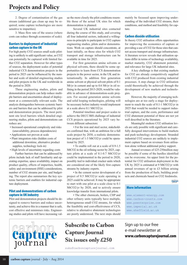
Barriers to deployment of industrialcarbon capture in the UK For high purity CO2 sources small scale pilot-
ing is unlikely to add significant value, as CO2
can potentially be captured with limited fur-
ther CO2 separation. However for other types
of sources, the deployment scales of potential
industrial CCS demonstration projects in the
period to 2025 can be influenced by the num-
ber and scale of detailed engineering studies
and pilot projects in the UK and worldwide in
the period to 2020.
These engineering studies, pilots and
demonstration projects can help reduce multi-
ple barriers and uncertainties ahead of deploy-
ment at a commercially relevant scale. The
analysis distinguishes between systemic barri-
ers and barriers that can be addressed by pilot
and demonstration projects. The most perti-
nent site level barriers which detailed engi-
neering studies, pilots and demonstrations can
reduce are:
• Increased operational complexity and risks
(unavailability, process dependencies)
• Applications not proven at scale
• Plant integration risks (hidden costs of
additional downtime, alternative product
supplies, technology lock-in)
• High levels of uncertainty regarding costs
Further barriers that can be addressed by
pilots include lack of staff familiarity and op-
erating expertise, space availability, impact on
product quality, effects of impurities, health,
safety and environment (HSE) considerations,
number of CO2 streams per site, and budget-
ing. The report also summarises the key sys-
temic barriers and enablers for industrial cap-
ture deployment.
Pilot and demonstrations of carboncapture in UK industry Pilot and demonstration projects should be de-
signed to remove barriers and reduce uncer-
tainty, and achieve this in a manner that is safe,
cost effective and minimises risks. Engineer-
ing studies and pilots will have increasing val-
ue the more closely the pilot conditions resem-
ble those of the actual UK sites for which
demonstration is planned.
Several UK industrial sites contacted
during the course of this study, and covering
all four industrial sectors, indicated a willing-
ness-in-principle to participate in CO2 capture
engineering studies, pilots and/or demonstra-
tions. Work on capture should concentrate, at
least initially, on those sites for which CO2
transport and storage infrastructure can be
available in time for 2025.
For first generation amine solvents or
physical solvents, there should be some op-
portunities to learn from CCS demonstration
projects in the power sector, in the UK and in-
ternationally. In addition first generation
amine solvent or physical solvent pilots of 0.1
Mt/yr in cement and up to 0.6 Mt/yr in oil re-
fining in the period 2015-2020, would be valu-
able in advance of demonstration-scale proj-
ects. For second generation amine solvents
and solid looping technologies, piloting will
be necessary before industry would implement
at a scale above 0.1 MtCO2/yr.
Potential timelines and project scales to
achieve the DECC/BIS challenge of industrial
CCS projects operational by 2025 vary be-
tween different subsectors:
• For the iron and steel sector, stakehold-
ers confirmed that, with an ambition for a full
scale project by 2030, a realistic demonstra-
tion project of 1-3 MtCO2/yr could be opera-
tional by 2025.
• To enable roll out at a scale of 0.9-1.5
MtCO2 in the oil refining sector by 2025, cap-
ture pilots at a scale of 0.1-0.7 MtCO2/yr
could be implemented in the period to 2020,
possibly tied to individual cracker units which
are considered one of the likely first capture
streams by industry experts.
• In the cement sector development of a
project of 0.5 MtCO2/yr scale operating in
2025 could be achieved. It may be appropriate
to start with one pilot at a scale close to 0.1
MtCO2/yr by 2020, and to actively ensure
knowledge transfer from international pilots.
• The other chemicals, boilers, CHP and
other refinery units typically have multiple,
heterogeneous small CO2 streams, for which
the feasibility and cost-effectiveness of CCS,
relative to alternative abatement technologies
are poorly understood. The next steps should
mainly be focussed upon improving under-
standing of the individual CO2 streams, their
conditions, and method and feasibility for cap-
ture.
Carbon dioxide utilisation In theory CO2 utilisation offers opportunities
for improving the economics of capture or
providing a use of CO2 for those sites that can-
not access transport and storage infrastructure.
A literature review reveals that utilisation op-
tions differ in terms of technology availability,
market maturity, CO2 abatement potential,
and relevance for large UK industrial sites.
A key challenge is that existing markets
for CO2 are already competitively supplied
with CO2 produced from existing industrial
processes. A step change in CO2 utilisation
could theoretically be achieved through the
development of new markets and technolo-
gies.
However, the majority of emerging tech-
nologies are at too early a stage for deploy-
ment to reach the scale of 0.1-1 MtCO2/yr in
2025 that would be needed to support indus-
trial capture, and the costs, performance and
CO2 abatement potential of these are not yet
well described in the literature.
Meaningful onshore CO2 utilisation lev-
els are only possible with significant and care-
fully designed interventions to build markets
and push technology development. Stranded
industrial CO2 sources are unlikely to imple-
ment capture based on revenues from utilisa-
tion alone without additional policy support.
Annual revenues of £25-250million may
be possible if some of the hurdles identified
can be overcome. An upper limit for the po-
tential for CO2 utilisation deployment in the
UK by 2025 is estimated at 9 MtCO2/yr with
annual revenues of up to £3 billion arising
from the production of fuels, building prod-
ucts and chemicals based on CO2 feedstocks.
More information
www.element-energy.comwww.carbon-counts.comwww.psenterprise.comwww.imperial.ac.ukwww.sheffield.ac.uk
Subscribe to Carbon
Capture Journal
Six issues only £250
Sign up to our free e-mail newsletter atwww.carboncapturejournal.com
CCJ40_Layout 1 29/06/2014 15:31 Page 10

July - Aug 2014 - carbon capture journal 11
Projects and Policy
Alberta is a province with great energy re-
sources, including sizable reserves of oil, nat-
ural gas, and coal. This presents both an op-
portunity and a challenge to the province. Al-
berta’s carbon capture and storage program
has taken some of the challenges inherent
with the responsible development of its 168
billion barrels of oil sands resources and
turned it into a carbon capture opportunity.
Almost all (99 per cent) of Alberta oil
reserves are oil sands – a naturally occurring
mixture of bitumen, sand, clay or other min-
erals and water. Buried under the province’s
northern forests, the development of the
province’s bitumen resource has been an ex-
tensive exercise in land use planning, envi-
ronmental monitoring and developing the
right technologies.
The Alberta government strives to de-
velop its energy resources in the most envi-
ronmentally responsible way possible. One
of the ways it has done so is by establishing
a single regulator as part of a larger integrat-
ed resource management system. The gov-
ernment has enhanced each piece of the pre-
vious regulatory system, including monitor-
ing and reporting, and created a more effi-
cient system to support continued growth
and environmental management.
With large-scale bitumen upgrading un-
derway, the province recognizes carbon cap-
ture and storage (CCS) is one way to signif-
icantly reduce greenhouse gasses. Other ini-
tiatives include developing the province’s
vast potential for renewable energy, includ-
ing hydroelectricity, wind power and solar
energy, and promoting energy efficiency. A
lberta’s Energy Minister, Diana Mc-
Queen, is eager to share with global audi-
ences the progress made on the province’s
carbon capture projects. "Our CCS program
is doing what we want it to do, and that's
making sure that as we grow our economy
and become a global energy supplier we are
doing it in a responsible way and reducing
our emissions here in the province."
In 2009, the Alberta government began
its CCS program by committing up to $2 bil-
lion for large-scale projects and making
changes to legislation that enabled CCS.
Through a competitive process $1.3 billion
was committed to two large scale CCS proj-
ects over a 15-year period (2010 to 2025) –
the Alberta Carbon Trunk Line / Sturgeon
Refinery and Quest. The funding program
has been designed in a way that the projects
receive funding only when certain bench-
marks have been achieved and verified. This
provides assurance to provincial taxpayers
that their money is well spent and that the
projects are meeting specific targets.
To ensure success in the projects, the
Alberta government undertook a Regulatory
Framework Assessment, which looked at the
rules for CCS in Alberta and best practices
from around the world. Over 100 global ex-
perts on CCS, including representatives from
industry, environmental groups, scholars and
government worked on this review. The
process, which began in 2011, released its
report in August 2013, and produced 71 rec-
ommendations and conclusions on how to
improve CCS in the province.
The final recommendations in the re-
port will help strengthen all aspects of CCS
within Alberta, including clearly defining the
roles and responsibilities of the agencies that
regulate CCS in Alberta and creating clear
approval requirements; encouraging cooper-
ation and fair development of CCS among
operators; reviewing notification require-
ments for those living in the area where large
scale carbon sequestration is underway; and
ensuring access to sites for monitoring,
measurement and verification activities. An-
other recommended action is to clarify the
details of the Post-Closure Stewardship
Fund, including obligations from operators
to contribute to this fund. Alberta Energy, the
government department responsible for en-
ergy development policy in the province, has
committed to further examination and imple-
mentation of the recommendations over
three years. This will ensure the appropriate
policies and regulations are in place for
when the CCS projects begin operation in
2015 and 2017.
Enhance Energy is building a 240-kilo-
metre Alberta Carbon Trunk Line connect-
ing a bitumen upgrader and fertilizer plant
outside of Edmonton with enhanced oil re-
covery projects . The plant, better known as
the Sturgeon Refinery, will be the first refin-
ery in Canada with built-in carbon capture
capacity.
The project is estimated to cost nearly
$1.2 billion, with the company contributing
$640 million, the Alberta government invest-
ing $495 million over 15 years, and the Gov-
ernment of Canada contributing $63.3 mil-
lion. Development is well underway at the
Minister of Energy Diana McQueen and Conservative MP Mike Lake tour the Quest CarbonCapture and Storage facility at Shell's Scotford plant near Fort Saskatchewan on April 17, 2014.The project is retrofitting the Scotford bitumen upgrader for carbon capture, designed for up to1.2 million tonnes of carbon captured per year, piped 80 kilometres north and injected morethan two kilometres below the Earth's surface. (Photo: Chris Schwarz/Government of Alberta)
Alberta continues to support CCSThe Province of Alberta, Canada is continuing to invest in two carbon capture and storage projects: theAlberta Carbon Trunk Line and Quest Project.By the Government of Alberta
CCJ40_Layout 1 29/06/2014 15:31 Page 11

carbon capture journal - July - Aug 2014
Projects and Policy
Quest Project is on track for commissioning
to begin at the end of 2014 and production
in the second quarter of 2015.
McQueen sees the progress being made
on the carbon capture units as important
component in Alberta’s approach to resource
development. “Enhanced recovery is anoth-
er positive impact of CCS projects. For Al-
berta this technology will allow for more ef-
ficient recovery of our resources and a
greater return for citizens with less environ-
mental impact. “
In addition to the benefit that CCS is
bringing to Alberta and its energy industry, a
fundamental part of Alberta’s CCS program
is sharing its learnings with other jurisdic-
tions and stakeholders as they move forward
with their own initiatives. Both projects are
required to share technical information on
their projects, and this information has been
made available on the Alberta Energy web-
site making it available to stakeholders from
around the world. “We know that CCS is a
powerful tool against climate change and the
more jurisdictions taking advantage of this
technology will be better for our planet and
for future generations,” said McQueen.
The knowledge sharing efforts are ex-
pected to lower the cost of future CCS proj-
ects, and capitalize on expertise from around
the world to improve CCS in Alberta. One
government in particular that is paying at-
tention to what is going on in Alberta is Chi-
na, where sharing information on CCS was
included in a Memorandum of Agreement
between China and the province of Alberta
in October 2013. Delegations from around
the world have been visiting Alberta to learn
more about the projects underway and the
policy work being done within government.
Alberta’s commitment to CCS is un-
precedented for a jurisdiction of 4 million
people, and speaks to the importance the
province places on responsible development
of energy resources the world wants
and needs.
refinery site and it is expected to begin oper-
ation in 2017. Refinery aside, the partnership
also continues to work on regulatory ap-
provals and right of ways for its carbon
pipeline.
The Quest project, a partnership of
Shell, Chevron and Marathon Oil, involves
retrofitting an existing bitumen upgrader
outside of Edmonton for CCS and then pip-
ing the carbon dioxide 64 kilometres north
where it will be permanently sequestered
more than two kilometres below the surface.
The project is estimated to cost $1.35 billion,
with the Quest partners contributing $485
million, the Alberta government $745 mil-
lion and the Government of Canada $120
million.
Currently, the Quest project is half con-
structed, with all major regulatory approvals
granted in 2013. Construction is underway
at the upgrader site, on the pipeline and at
the sequestration site. Additionally, work on
the baseline monitoring, measurement and
verification is underway, including work on
ground water and biosphere sampling. The
More informationwww.energy.alberta.ca
CCS - getting itmoving
Rotterdam World Trade Center, 23rd Floor Rotterdam, November 12
Register now for an early bird discount!
What is the best way to get CCS moving inNorth West Europe?
Register at carboncapturejournal.com
Speakers include
Jos Cozijnsen, MMA, Consulting Attorney emissions trading, emissierechten.nl andparticipant of the ZEP forumHow carbon trading / cap + trade can be part of a CCS financial business case
Harsh Pershad, Principal Consultant, Element EnergyBlueprint for a financially efficient offshore transport, storage and CO2-EOR network in theNorth Sea
Only 50€ until the end of Aug
CCJ40_Layout 1 29/06/2014 15:31 Page 12

July - Aug 2014 - carbon capture journal 13
Projects and Policy
CCS in the Netherlands - and the future ofROAD
n
m
ROAD, the Dutch flagship CCS project, is currently “essentially mothballed” while the project team waitfor financing. Speakers at the CATO conference discussed who should be doing more to get it moving –industry or government?
The ROAD project, to capture CO2 from a
new power plant located on the Maasvlakte,
in the Port of Rotterdam, and store the CO2
in a depleted gas reservoir in the North Sea,
just 25km away, is currently “essentially
mothballed” while the project team wait for
financing to be agreed, said capture director
Andy Read.
He was speaking at the 7th Dutch CCS
Symposium of Dutch research organisation
CATO in Amsterdam on June 19-20.
CATO stands for CO2 Afvang, Trans-
port en Opslag, or CO2 capture, transport
and storage. ROAD stands for Rotterdam
Opslag en Afvang Demonstratieproject or
Rotterdam Capture and Storage Demonstra-
tion Project.
All the engineering for ROAD is com-
plete, Mr Read said. So far the EU has com-
mitted Eur 180m to ROAD, the Dutch gov-
ernment ‘up to’ Eur 150m, and the Global
Carbon Capture and Storage Institute (GCC-
SI) up to Eur 5m.
ROAD aims to capture CO2 from a
new power plant located on the Maasvlakte,
in the Port of Rotterdam, and store the CO2
in a depleted gas reservoir in the North Sea,
just 25km away.
“It is one of the best CCS projects,” Mr
Read said. Being next to the sea, the capture
plant doesn’t need cooling water. There is a
huge amount of industry adjacent to the
North Sea [which could provide CO2]. Rot-
terdam already pumps CO2 to greenhouses
to fertilise plants, and “this could be extend-
ed”.
The ROAD project was launched in
2008, after E.ON agreed it could be connect-
ed to its new power plant. The project then
became a key pillar of the Rotterdam Cli-
mate Initiative project.
Over the past six years the ROAD team
has worked closely with CATO researchers
on many aspects, including power plant in-
tegration, managing emissions, and flow as-
surance, he said.
For example there were concerns that
the high pressure CO2 would freeze as it en-
tered the low pressure (20 bar) reservoir and
expand, and CATO did research to try to
work out what would happen.
will decrease enormously in price.”
Mr de Vries said he expected to see rap-
id change in the energy industry in coming
years. “There will still be centralised produc-
tion, but there will be a lot of other produc-
ers,” he said.
“10 years ago, you knew all the produc-
ers [companies producing electricity],” he
said. “Today there are 125 different players
producing electricity, producing it at very
different moments. There will be more and
more producers.”
“In that world, CCS needs to have a
place.”
Shell NederlandDick Benschop, president-director of Shell
Netherlands and Vice-President Gas Market
Development, and a former Dutch deputy
Minister for foreign affairs, talked about the
Barendrecht CCS project which Shell aimed
to operate in the Netherlands in 2007-2010.
Bert de Vries
Bert de Vries, Deputy Director-General, De-
partment Energy and Sustainability Dutch
Ministry of Economic Affairs, pointed out
that ROAD is one of the biggest projects the
Dutch government is considering altogether,
comparable in size to major defence invest-
ments.
Mr de Vries said he would like to see
more industry involvement in the project.
“I'm a bit disappointed we in government are
trying to find a solution, and there is not a
big call from industry to join us,” he said.
“If this [CCS] is not a strategic decision
for industry, then we do have a problem. It
cannot be that this is only government busi-
ness.”
From the government perspective,
“CCS is a big challenge because it’s new,”
he said. “You have competitors [for govern-
ment funding] - solar and wind. I'm sure they
CATO research discussion – caption – A panel of CCS researchers from around the world werebrought together at the CATO conference. From left to right: Professor Wei Wei, of ShanghaiAdvanced Research Institute (China); Jon Magne Johansen of Big CCS Centre in Trondheim(Norway); Stuart Haszeldine of the Scottish CCS Centre (UK); Jon Gibbins of the UK CCS ResearchCentre; Jan Brouwer of CATO (Netherlands); Robert Kleiburg of TKI Gas/ECN (Netherlands); andIsabelle Czernichowski-Lauriol of CO2GeoNet (France).
CCJ40_Layout 1 29/06/2014 15:31 Page 13
carbon capture journal - July - Aug 201414
Projects and Policy
Barendrecht is a suburb of Rotterdam,
and the project aimed to store carbon diox-
ide there.
Public campaigning led to the project
being abandoned, despite intervention by
Jacqueline Cramer, then Minister of Envi-
ronment, and Maria van der Hoeven, then
Minister of Economic Affairs.
Inhabitants feared the plan would en-
danger the town and lead to a fall in house
prices.
“We all thought it was a great idea, it
couldn't be better, but that was not the idea
of the inhabitants,” Mr Benschop said.
The story of how relations with local
inhabitants was handled is now seen as “a
story of how not to do it,” he said.
As a result, “you'll probably see CCS
10 per cent cost off, and repeat a number of
times,” he said.
When it comes to finding the right fi-
nancing arrangement, “UK is leading in Eu-
rope in terms of doing it with contracts for
difference,” he said.
Mr Benschop was asked if he thought
there should be alternative approaches to the
emissions trading scheme in achieving a low
carbon society, on the basis that ETS has not
been very successful so far.
“I find the UK example on the carbon
floor price an interesting one,” he said. There
could also be “ETS reform, to get into a
more meaningful CO2 price.”
“If you look at transport, the cost of
abatement is in triple figures [in terms of the
money you have to spend to avoid a ton of
going offshore for a while,” he said. “But at
some point in time we hope we would be
able to come onshore.
“I think that would be difficult now.”
Mr Benschop did not explain why Shell
is not involved in ROAD.
Mr Benschop cited International Ener-
gy Agency figures from 2013 showing that
“a global delay in CCS deployment would
cause an increase in costs for power sector
decarbonisation of $1 trillion”.
He cited UK Energy Technology Insti-
tute data showing “without CCS the addi-
tional costs to run a decarbonised UK econ-
omy in 2050 will be £32bn per annum.”
The best way to reduce CCS costs
might simply be to build more CCS plant, he
said. “You double [global] capacity and get
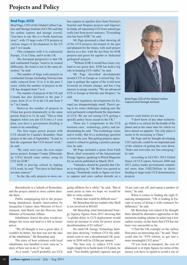
Brad Page, GCCSIBrad Page, CEO of the Global Carbon Cap-
ture and Storage Institute (GCCSI) said that
for carbon capture and storage overall,
"you have to say this is a North American
story", with 19 large scale CCS projects at
various stages of development in the US
and 7 in Canada.
This compares with 4 in continental
Europe, 13 in China, and 6 in the UK.
The European perspective is that UK
and continental Europe "need to be treated
differently, the trend is not in the same di-
rection," he said.
The number of large scale projects in
continental Europe (including Norway) has
sadly reduced from 14 to 4 in the past 3
years, whilst the number of projects in the
UK has dropped from 7 to 6.
The number of projects in the US and
Canada has also declined in the past 3
years, from 25 to 19 in the US and from 9
to 7 in Canada.
However the number of projects in
China has grown dramatically in the same
period, from 6 to 13, he said. "This is what
happens when you put CCS into a 5 year
plan, you have a government deciding it
wants to do something."
The first major power project with
CCS should be Canada's Boundary Dam
project at the end of September. "It puts to
bed the argument that CCS doesn't work,"
he said.
"By early next year, the next major
power project, Kemper County [Mississip-
pi, USA] should come online, using its
CO2 for EOR."
EOR is proving critical in making
CCS work, he said. "You have to find these
revenue sources."
So far, the only projects to store car-
bon capture in aquifers have been Norway's
Snøvhit and Sleipner projects and Algeria's
In Salah, all separating CO2 from natural gas
wells (not from power stations). "Everything
else has been EOR," he said.
Mr Page presented a chart showing all
of the CCS projects developed in the past
and planned for the future, with each project
shown as a dot, with the dot blue for EOR
projects and green for aquifer or 'dedicated
geological' projects.
"Without EOR it would have been very
hard to see green dots. EOR has held a big
role in keeping CCS viable," he said.
Mr Page described developments
around CCS in Europe as 'a mixed bag'. Eu-
rope is perhaps the region of the world most
focussed on climate change, and has a big
interest in energy security. "We see advanced
CCS in Europe at Snøvhit and Sleipner," he
said.
"But regulatory developments [in Eu-
rope] are disappointingly small. There's go-
ing to be some challenges making sure the
next parliament comprehends the importance
of CCS. We are not seeing CCS getting a
specific policy focus except in the UK."
There are 3 components to the CCS
business case: technology, policy and un-
derstanding he said. "The technology exists
and it works. But it's a technology question
to lower the cost. But getting projects opera-
tional is critical to gaining a positive percep-
tion, he said.
Mr Page included a quote from Fatih
Birol, chief economist of the International
Energy Agency, speaking to Wired Magazine
for an article published in March 2014.
"Outsiders should be grateful that Chi-
na is weighing in," Mr Birol was quoted as
saying. "Somebody needs to figure out how
to capture and store carbon dioxide on a
massive scale before it's too late.
"I don't know of any other technolo-
gy which is so critical for the health of the
planet and at the same time for which we
have almost no appetite. The only place it
seems to be increasing is China."
Mr Page said he thought developing
CO2 networks could be an important part
of the solution of getting the costs down.
"Hubs and networks are fast emerging,"
he said.
According to GCCSI’s 2013 Global
Status of CCS report, between 2008 and
2012, policy leader governments commit-
ted more than US$22billion in direct
funding to large-scale CCS demonstration
projects.
Brad Page, CEO of the Global CarbonCapture and Storage Institute
CCJ40_Layout 1 29/06/2014 15:31 Page 14

July - Aug 2014 - carbon capture journal 15
Projects and Policy
regulatory framework is there, he said.
Having a “demonstration project will
prove it can work,” he said.
We need more understanding of how
CO2 + EOR works, and we also have to de-
velop a legal infrastructure for cross border
CO2 transport, he said.
It would be possible to start doing car-
bon capture in the North Sea now by using
gas tankers, he said, rather than wait for the
pipelines and offshore infrastructure to be
developed.
One audience member questioned
whether the carbon capture industry should
be attacking the wind sector harder, since it
is winning all the government attention. “We
[CCS people] have had a policy of not at-
tacking renewables, but I think we're going
to have to erode that false hope [in wind
power]”, the audience member said.
“I think it is tricky to attack renewables,
you end up in the lap of the devil,” Mr
Haszeldine replied.
“You can just point out, renewables
supply 4 per cent of energy. We love renew-
ables but we need more. Do we want to live
with 4 per cent of our energy?”
More informationYou can download presentations from the
CATO conference at:
http://bit.ly/CATO2014
CO2 being emitted]. “So we are not able to
live with a 30-40 euro CO2 price.”
“There is one alternative, performance
standards for the power sector,” he said.
So when it comes to finding funding for
CCS, as industry, “we don't lack objectives,
we lack policy instruments,” he said.
Stan DessensStan Dessens, conference chairman and a
former Director General of the Energy Min-
istry of Economic Affairs for the Nether-
lands, noted that there are many companies
who benefit from ETS being as low as it is,
and many people who complain ETS is too
low who would also like to see an alterna-
tive system.
Mr Dessens also noted that Chris
Davies, a former Member of the European
Parliament for North West England with the
Liberal Democrat Party, had been the biggest
advocate for Carbon Capture and Storage in
the European Union. He lost his seat in the
2014 European Elections. He hopes that an-
other MEP will replace Mr Davies as a CCS
advocate.
The most important energy topic in
Brussels at the moment is “security of sup-
ply,” he said. “It would be quite easy in Brus-
sels at the moment to get a billion euros for
energy security.”
Ward GoldthorpeWard Goldthorpe, program manager for CCS
and gas storage with the Crown Estate in the
UK, noted that in the UK people no longer
talk about ‘demonstration’, but talk about
getting projects to the full scale.
Mr Goldthorpe also noted that the UK
has managed to get CCS projects running by
concentrating on getting large scale projects
running and developing a suitable system for
investors (contracts for difference), rather
than spending money on research.
Jon Gibbins, UKCCSRCJon Gibbins, Professor of Power Plant Engi-
neering and Carbon Capture with the Uni-
versity of Edinburgh, said he thought it was
time we saw a range of second and third gen-
eration CCS projects, building on the first
generation projects done so far.
Most of the CCS projects still on the
table are first generation projects, he said.
But it is also interesting to note that the
two UK projects which are moving ahead,
White Rose and Peterhead, are comparative-
ly new projects, with discussions only start-
ing about a year before the FEED funding
was confirmed last year.
Mr Gibbins noted that CCS might take
off earlier in developing countries, now or-
ganisations such as the World Bank and
Asian Development Bank (ADB) are refus-
ing to fund new coal power plants which
don’t have CCS.
When it comes to who pays for CCS,
Mr Gibbins thought it was the wrong ques-
tion, since ultimately “it is the customers
who pay.”
Stuart Haszeldine, University ofEdinburghStuart Haszeldine, professor of carbon cap-
ture and storage at the School of Geo-
sciences, University of Edinburgh, said that
in his view, there is still not enough public
or political demand for carbon capture, so it
is not rising high enough up the political
agenda.
“The public don't understand that we've
got to make choices,” he said.
Carbon capture and storage “has to be
something which feels inevitable,” he said.
“The politicians have to believe it is possi-
ble and can be done now. “Public perception
feeds the government.”
“If the Dutch government wanted
ROAD they'd find EUR 250m by the end of
the week,” he said.
Because politicians don’t think the pub-
lic thinks there is a problem, they are not giv-
ing a signal to industry that it should be in-
vesting in CCS.
“Companies will do it when they have
to,” he said.
On the plus side, the industry has pub-
lic ‘permission’ to store offshore, and the
Mr Page presented a chart showing all of the CCS projects developed in the past and plannedfor the future (see box text opposite)
CCJ40_Layout 1 29/06/2014 15:32 Page 15

carbon capture journal - July - Aug 201416
Projects and Policy
The UK Energy and Climate Change (ECC)
Committee report examines the progress of
CCS in the UK as well as setting out a num-
ber of recommendations on how to over-
come barriers to deployment. In particular,
the ECC Committee recommends that the
Government should “commit to a realistic
but ambitious timeline for awarding support
to projects both inside and outside its CCS
commercialisation competition”.
"Fitting power stations with technolo-
gy to capture and store carbon is absolutely
vital if we are to avoid dangerously destabi-
lizing the climate," said Energy and Climate
Change Committee Chair, Tim Yeo MP. "Af-
ter nearly a decade of delay DECC has final-
ly got near to delivering two pilot Carbon
Capture and Storage projects in the UK. It
must now fast-track these projects and reach
final investment decisions before the elec-
tion to ensure this technology can start de-
livering carbon savings by the 2020s."
"These two demonstration projects will
not be enough to kick-start the industry or
have a significant impact on our carbon
budgets, however. Ministers must also en-
sure that viable CCS projects not involved
in the competition are able to apply for guar-
anteed-price contracts alongside other low-
carbon energy schemes."
CommentsThe Carbon Capture and Storage Associ-
ation (CCSA) welcomed the report, Luke
Warren, Chief Executive of the CCSA, com-
mented:
“The ECC Committee’s report on CCS
and its recommendations is extremely time-
ly – and we very much share their concerns
and frustrations on the substantial delay to
the development of CCS in the UK.
We strongly support the recommenda-
tions of the Committee, particularly in rela-
tion to the need for speed on projects both
within and outside of the CCS competition.
As well as highlighting the importance
of successfully concluding the current com-
petition we are extremely pleased to see that
the Committee has identified the need for
clarity surrounding the availability of CfDs
for non-competition projects. There is a very
real risk that, without a strong signal that these
projects can access a CfD in parallel with the
competition, these projects will be shelved.
stones, the UK must have another five proj-
ects under construction by 2020.
Professor Stuart Haszeldine, SCCS Di-
rector, said: “We all want a secure future,
which includes low-carbon energy. Develop-
ing five CCS projects now will cost each UK
household around £30 per year. The UK
needs more than 30 of these to start building
before 2025. To avoid extra costs later, we
must develop our CO2 storage now. That is
a good insurance premium against the 100%
certainty of future carbon taxes and future
global change. Avoiding CCS investment
may look cheap today, but is storing up high-
cost trouble for later.”
Ironically, three fully commercial proj-
ects await the UK Government’s use of mar-
ket powers, which already exist, to kickstart
development. Summit Power’s CCS propos-
al at Grangemouth could create 5,000 con-
struction jobs from 2015, 2Co Energy’s Don
Valley CCS Project in Yorkshire was once a
leading European project, and Teesside Low
Carbon could decarbonise a large part of the
UK chemical industry. All are withering due
to a lack of government attention. All could
pipe CO2 offshore to produce additional oil
recovery from depleted fields, which would
more than pay for their costs through oil tax
revenue."
There is
no credible
scenario for
cost-effective-
ly tackling cli-
mate change
without CCS.
The sooner we
build the first
projects, the
sooner we will
be on the path
towards meet-
ing this goal
whilst deliver-
ing the signifi-
cant benefits
that a mature
CCS industry
can offer.”
Scottish Carbon Capture and Stor-
age (SCCS) said that everybody was agreed
CCS is essential for the future of UK low-
carbon electricity.
The UK is uniquely positioned for de-
veloping CCS, said SCCS. It has inventive
manufacturers to develop CO2 capture
equipment, industries to engineer equipment
and pipelines, and a world-leading offshore
hydrocarbon industry to undertake safe and
secure CO2 storage. The Committee states
that the UK should concentrate on develop-
ing its massive, and potentially profitable,
offshore storage in depleted oilfields and
saltwater aquifers – hundreds of years’
worth. And it points out that the UK Gov-
ernment should better inform its public about
the benefits.
The UK has an outstanding civil serv-
ice, which has delivered the correct legisla-
tion, regulation and electricity market reform
rapidly and to the highest quality. Two full-
chain CCS commercialisation projects (Peter-
head, Aberdeenshire; and White Rose, York-
shire) are also being examined, but they will
not begin operating until 2018 at the earliest.
Why is the UK so slow at developing
this technology, which the Committee says
will reduce wholesale electricity costs in
2030 by 20% – and will halve the extra cost
of low-carbon power by 2050, according to
the Energy Technologies Institute? The de-
livery of CCS takes time to build the neces-
sary equipment. If we are to meet these mile-
More informationwww.parliament.uk
MPs urge the Government to 'fast track' CCSMPs in the UK have urged the Government to fast-track final funding decisions on two pilot Carboncapture and storage projects at Peterhead and Drax by early 2015.
CCS Cost Reduction Task Force’s cost reduction trajectory (Source: CarbonCapture and Storage Association)
CCJ40_Layout 1 29/06/2014 15:32 Page 16

July - Aug 2014 - carbon capture journal 17
Projects and Policy
IEA report confirms CCS critical but tooslow www.iea.orgThe International Energy Agency (IEA)
has published the fourth volume of its En-
ergy Technology Perspectives report,
which concludes that business-as-usual is
not an option if we are to transition to a
sustainable energy future.
The report underlines that Carbon Cap-
ture and Storage has a critical role to play in
decarbonizing the power sector and energy
intensive industries as well as supporting en-
ergy efficiency.
Speaking after the publication of the re-
port, Dr. Graeme Sweeney, ZEP Chairman,
said, “We commend the IEA for this com-
prehensive report that reiterates the value of
CCS in the mitigation of CO2 emissions.
The report’s conclusions come at a crucial
time in EU energy policy discussions on en-
suring security of supply for Europe, while
staying in line with our emission reduction
objectives. Following recent political devel-
opments in its eastern neighbourhood, the
EU faces an uncertain energy future. It is
clear that we must increasingly look towards
our indigenous energy sources – CCS plays
an essential role in enabling this.”
“The IEA has made clear that CCS is
crucial for decarbonizing large-scale fossil
fuel use for power generation and in energy-
intensive industry. The agency previously
concluded that in principle this technology
can reduce full life-cycle CO2 emissions
from fossil-fuel combustion at power stations
and industrial sites by 65-85%. Moreover, by
providing flexible back-up power, CCS is an
essential complement to renewables and en-
ergy efficiency,” Sweeney added.
Yet, the IEA has confirmed, as ZEP has
often pointed out, that the deployment of
CCS is occurring too slowly due to high
costs and a lack of political and financial
commitment. Increased progress in CCS re-
search, development and demonstration is
needed to ensure cost-competitiveness and
timely deployment.
“Based on ZEP’s own analysis, if we
act now, with the right investment frame-
work and support measures, CCS can be-
come commercially available post 2030. The
next step is to scale up to large, integrated
projects, which have a huge potential to
drive down costs. This is achievable through
the introduction of transitional support meas-
ures and the creation of a level playing field
with other low carbon technologies. Ulti-
mately, the EU must embed CCS in its ener-
gy security strategy and 2030 energy and cli-
mate framework,” Dr. Sweeney concluded.
DOE recovery act project begins www.rti.orgThe project at Polk Power Plant will
demonstrate warm syngas desulfuriza-
tion and CO2 capture.
The Department of Energy, RTI Inter-
national and Tampa Electric Company
(TECO) have completed the successful
startup of a pilot project to demonstrate
carbon capture technology in a coal gasifi-
cation unit at the Polk Power Plant Unit-1
in Tampa, Florida.
The gasification process converts car-
bon-based materials such as coal, petrole-
um coke and biomass into syngas, which
requires cleanup and conditioning steps be-
fore being used for the production of elec-
trical power or industrial products such as
chemicals, fertilizers, fuels, or hydrogen.
RTI's technology removes contami-
nants such as sulfur and heavy metals at
warm process temperatures, eliminating
the need for substantial syngas cooling and
expensive heat recovery systems. This
would significantly increase the thermal ef-
ficiency and reduce the capital and operat-
ing costs of new gasification-based sys-
tems when compared to conventional
process technologies.
The newly installed pre-commercial
demonstration facility will use about 20
percent of the raw syngas from Tampa
Electric’s existing 250 megawatt electric
Polk 1 coal- and petcoke-fueled integrated
gasification combined cycle (IGCC) plant
as its input feed stream. It will remove
more than 99.9 percent of the sulfur con-
taminants from the raw syngas at gasifier
pressure and warm process temperature.
In addition to demonstrating warm
syngas desulfurization, the RTI system al-
so includes a water-gas-shift reactor to en-
rich the hydrogen content of the cleaned
syngas and will demonstrate an advanced
activated amine process for capture of
more than 90 percent of the carbon dioxide
from the syngas stream. Following clean-
up, the hydrogen-enriched syngas will be
re-introduced to the Polk 1 plant and com-
busted in the existing syngas turbine.
The Department of Energy has a long
history of collaboration with TECO at the
Polk Power Station, starting more than 20
years ago when DOE helped fund construc-
tion of the plant.
Gas cleaning at power plants to re-
move contaminates like carbon dioxide,
mercury, and sulfur is typically done at low
temperatures. IGCC technology, or warm
gas cleanup, has posed a technical chal-
lenge to scientists for more than 30 years.
It has the potential to improve the energy
efficiency of removing pollutants from coal
power plant emissions, reducing the over-
all cost of capturing carbon dioxide and
other contaminant emissions from power
plants while also increasing reliability.
IGCC also has the potential for local
economic benefits. The technology in-
creases the possibility that the captured
carbon dioxide can be turned into a new
revenue stream for operators by converting
Policy, projects and regulation news
Tampa Electric Company’s Polk Power Plant will host an IGCC carbon capture pilot project
CCJ40_Layout 1 29/06/2014 15:32 Page 17

carbon capture journal - July - Aug 201418
Projects and Policy
it into other uses, like fertilizer and en-
hanced oil recovery. The project, which is
approximately $3 million under budget, in-
cluded $168 million American Recovery
and Reinvestment Act funding.
DOE awards $100M for innovativeenergy researchscience.energy.gov/bes/efrcThe money will fund 32 projects at En-
ergy Frontier Research Centers (EFRCs)
across the U.S. including several on
CCS.
The 32 projects were competitively
selected from more than 200 proposals. Ten
of these projects are new while the rest re-
ceived renewed funding based both on their
achievements to date and the quality of
their proposals for future research.
Twenty-three of the projects receiving
funding are headed by universities, eight
are led by the Energy Department’s Nation-
al Laboratories and one project is run by a
non-profit organization.
Awards range from $2 million to $4
million per year per center for up to four
fiscal years, subject to a progress review in
year two. DOE plans to open the EFRC
program to new applications every two
years.
Those realting to carbon capture and
storage include:
• Lawrence Berkeley National Laboratory
- Produce robust predictive models that
will greatly improve confidence in
subsurface carbon dioxide storage
systems by characterizing and
understanding carbon dioxide trapping
processes at the nano, meso, and macro
scales.
• University of California, Berkeley -
Create new synthesis strategies,
combined with novel characterization
and computational methods, for
tailoring materials for the efficient
separation of gases, such as natural gas,
hydrocarbons, and carbon dioxide.
• The University of Texas at Austin -
Understand and control emergent
behavior arising from coupled physics
and chemistry in heterogeneous
geomaterials, particularly during the
time and length scales for geologic
carbon dioxide storage
Since their establishment by the De-
partment’s Office of Science, the EFRCs
have produced 5,400 peer-reviewed scien-
tific publications and hundreds of inven-
tions at various stages of the patent
process. EFRC research has also benefited
a number of large and small firms, includ-
ing start-up companies.
Heriot-Watt University and the University of
Edinburgh. The three projects will yield cru-
cial results that will feed into each stage of
the CCS chain, from capturing CO2 within
flexible power generation systems to moni-
toring its transport in liquid state and ensur-
ing safe and permanent storage deep below
ground. A further two projects will involve
researchers from within the SCCS partner-
ship as co-investigators.
UKCCSRC has provided funding to
nine research institutes across the UK for a
total of 14 project collaborations. Seven
projects will focus on CO2 capture, five will
tackle cross-cutting issues and two will in-
volve CO2 storage. The winning bids have
attracted an additional £2m in co-funding
and support from industry partners.
Professor Stuart Haszeldine, SCCS Di-
rector, said, "The diversity and quality of ex-
pertise within the SCCS partnership has en-
abled us to secure an improved share of
funding for research that will support the
growing CCS industry in the UK. The
knowledge gained will also be applicable to
CCS projects worldwide, as many countries
begin to assemble the elements of a low-car-
bon economy. It is essential that academia,
industry and government continue working
together to refine our knowledge and
progress to commercial-scale deployment of
CCS technology."
CO2 Capture Project annual reportpublishedwww.co2captureproject.org The 2103 annual report details the work
of the group to advance the technologies
that will underpin the deployment of in-
dustrial-scale CO2 capture and storage.
In 2013 a number of significant proj-
ects were brought to conclusion with two of
the largest projects ever undertaken by CCP
– an OTSG oxy-firing capture demonstration
and a storage contingencies study – reaching
important milestones during the year.
The CO2 Capture Project (CCP) is an
award-winning partnership of major energy
companies, working to advance the tech-
nologies that will underpin the deployment
of industrial-scale CO2 capture and storage.
Since its formation in 2000, the CCP
has undertaken more than 150 projects to in-
crease understanding of the science, eco-
nomics and engineering applications of
CCS. The group has been working closely
with government organizations — including
the US Department of Energy, the European
Commission and more than 60 academic
bodies and global research institutes.
Phase Three (CCP3) members are: BP,
Chevron, Eni, Petrobras, Shell and Suncor.
UKCCSRC allocates £2.75M for research ukccsrc.ac.ukThe UK Carbon Capture and Storage Re-
search Centre (UKCCSRC) has today an-
nounced the allocation of £2.57 million
from its research budget to support 14
new CCS research projects.
The projects include 7 on CO2 capture
(£1,128,000), 5 on CO2 cross-cutting issues
(£1,040,000), and 2 on CO2 storage
(£399,000) and have attracted a total of £2
million in additional co-funding and support
from a broad range of industrial partners
from the UK and overseas.
Prof Jon Gibbins, Director, UKCCSRC
said, “It is great to have the UKCCSRC's
own research portfolio now fully under way.
Our big tasks for the next three years of the
Centre's life will be to see these projects ex-
ecuted successfully and to link them, and all
the academic research supported by the Re-
search Councils, DECC and other funders,
to maximise their value for supporting future
CCS delivery.”
The projects funded in this call are fun-
damental and multidisciplinary CCS re-
search projects that address research needs
identified by the Advanced Power Genera-
tion Technology Forum (APGTF) and the
DECC CCS Roadmap for Innovation and
R&D.
This call builds upon the £2.2million
allocated in 2012 for 13 projects in the
UKCCSRC’s first call. The 14 projects in the
second call will involve 9 different UK uni-
versities in the delivery of the research.
Two of the projects include significant
academic collaboration with Australia and
China. The Quantifying Residual and Disso-
lution Trapping at the CO2CRC Otway Proj-
ect Injection Site, excitingly involves collab-
oration with the Cooperative Research Cen-
tre for Greenhouse Gas Technologies
(CO2CRC) in Australia.
The UK Minister of State for Energy
and Business, Michael Fallon, announced
the funding during a visit to the Knowledge
Transfer Centre at the Advanced Manufac-
turing Research Centre in South Yorkshire
after he formally opened the UKCCSRC’s
Pilot-Scale Advanced CO2-Capture Tech-
nology (PACT) facilities in Beighton.
Scottish projects win research funding www.sccs.org.ukScientists from the Scottish Carbon Cap-
ture and Storage (SCCS) research part-
nership have competitively won a 20%
share of the £2.57 million funding.
Three out of 14 new CCS research proj-
ects, selected by the UK CCS Research Cen-
tre (UKCCSRC) as part of its second fund-
ing call, will be led by academics based at
CCJ40_Layout 1 29/06/2014 15:32 Page 18

19July - Aug 2014 - carbon capture journal
Capture and Utilisation
Coordinated by Centro de Investigación de
Recursos y Consumos Energéticos (CIRCE),
operational experience will be gained
through demonstrating the technology at
CIUDEN Technology Development Centre
for CO2 Capture (NW Spain).
The project objective is to demonstrate
the concept of second generation oxyfuel
combustion to reduce significantly the over-
all efficiency penalty of CO2 capture into
power plants, from approximately 12 to 6 ef-
ficiency points. The improvement in the
overall efficiency of power plants with CO2
capture requires the development and
demonstration of overhauled processes and
components throughout the whole system to
obtain an optimized combustion with high
oxygen levels (30-50% v/v basis).
The second generation oxyfuel concept
will consist of integrated high-efficiency op-
timised systems for oxygen production,
steam generation (boiler) and CO2 compres-
sion and purification, process integration and
application of conclusions to large power
plant designs.
The O2GEN project will draw conclu-
sions that will be included in future large
scale oxy-fuel power plants with Circulating
Fluidized Bed (CFB) technology and CIU-
DEN Technology Development Centre for
CO2 Capture is considered as an optimum
demonstration scale unit to carry out the
O2GEN project experimental campaigns and
to obtain complementary knowledge.
The following systems from CIUDEN
Technology Development Centre for CO2
Capture are within the O2GEN project
scope:
• Oxygen supply
• Fuel and sorbent feeding
• Combustor
• Cyclone, flue gas cooling and filter unit
• Ash discharge systems
• Flue gas recirculation system (RFG)
• Compression and Purification unit (CPU)
During the period late 2011-2013 an
extensive amount of information (opera-
tional as well data analysis) under different
European funded projects was acquired. In
Humidity by itself becomes a problem
when it reaches water dew point and con-
denses. During oxy-fuel, RFG are sent to the
fly ash silo to pneumatically transport the fly
ash to the furnace, for reburning. Blocking
problems appeared in these transport lines.
Water condensation was seen as the cause of
this issue. As a consequence two different
measures were adopted:
• Isolation was proposed in order to avoid
water condensation.
• A new commercial CO2 connection to the
main rotatory valve was set in order to
increase pneumatic transport. It is
expected for the near future to use
recirculated dry CO2 from the
compression and purification unit (CPU)
as an auxiliary service to avoid
condensation problems.The problem
described is enhanced by the high
moisture content in the fuel. Unlike in
air-firing operation, under oxy-fuel
combustion, gas for solids transport
(RFG) has higher humidity content and
lower oxygen concentration. This
consideration is important depending on
the type of fuel being used:
• For high volatile fuels, high oxygen
concentration in the solids transport fluid
lines may be an issue since combustion
may occur before entering the
combustion chamber.
• For sticky fuels, high humidity in the
pneumatic solids transport lines becomes
this article the main problems faced and so-
lutions developed over the past two years are
summarized. The lessons learned will serve
as improvements for the second generation
oxy-fuel power plants with CFB technology.
They are set as a first input for the O2GEN
project.
The installations have been improved
when problems arose. From those activities,
there has been some learning which can be
applied to second generation oxy-fuel com-
mercial power plants. Some of the problems
overcome are common to conventional pow-
er plants too. It must be kept in mind that
most of the improvements stated here have a
qualitative nature and have been concluded
at a maximum value of 28% volume oxygen
content in the oxidant.
Solids handlingFlue gas moisture content is higher in oxy-
combustion than in air combustion, imply-
ing new challenges in case these gases are
used for solids handling. There are two im-
portant recirculated flue gases (RFG) criti-
cal temperatures:
• Acid dew point temperature, when acid
gases in the RFG start condensing at
temperatures on the range of 130°C -
150°C.
• Water dew point temperature, when water
starts condensing at temperatures on the
range of 100°C - 80°C.
Optimisation of oxygen-based CFBtechnology with CO2 captureCIUDEN is working on the FP7 European O2GEN project, which focuses on one of the most importantrecommendations of the Zero Emission Platform´s (ZEP) report for the deployment of CCS in theEuropean Union: the use of higher O2 concentrations in oxyfuel combustion reducing the flue gasrecirculation and energy penalty.
Figure 1 - Flue gas circuit
CCJ40_Layout 1 29/06/2014 15:32 Page 19

20 carbon capture journal - July - Aug 2014
Capture and Utilisation
a problem and additional measures to
avoid blockages or unplug them are
necessary.
Proper design (pneumatically-sizing,
isolation by heat tracing, purge lines, etc.)
and the potential use of dried CO2 from the
CPU should be considered for solids trans-
portation.
Air infiltrationUnder real conditions it may not be practi-
cally feasible to seal the boiler and the flue
gas duct completely. Air ingress dilutes the
flue gas considerably and causes a loss of
sensible heat. There is additional compres-
sion consumption for rotating equipment too
and in the CPU there are limiting values be-
low which some units could not operate. All
these considerations imply a reduction in
CO2 capture efficiency, defined as the ratio
between the energy consumed per unit of
CO2 captured.
In CIUDEN corrective actions were
implemented such as the replacement of tex-
tile expansion joints and bolted connections
in flange unions by metallic expansion joints
and welded flange unions respectively. After
intensive works to reduce air infiltration, a
consistent CO2 concentration of more than
80% v/v (dry basis) has been achieved in the
flue gases.
LeakagesThe characteristics of the RFG with high wa-
ter content and some chemical species like
SO3, SO2, NOx, may cause any leakage from
the pressurized section (from the induced
draft fan to boiler) to condensate immediate-
ly into acid deposition when cooling down,
even affecting health and safety conditions at
site. Figure 2 shows some examples.
Welded flanged unions, leak-proof
• Oxygen is mixed with primary and
secondary oxidant streams after the force
draft fans. For high pressure lines in a
commercial plant, the fans should be
after the oxygen is mixed with RFG in
order to avoid fluctuations in the oxidant
stream.
• The feeding-water flue gas heat recovery
accumulates fly ash and needs a very
often shoot-blowing with steam during
oxy-fuel operation. Such shoot-blowing
affects the stability of the boiler. This is
an important aspect to pay attention to in
future flexible oxy-fuel configurations
since fly ash elutriation will be higher
under high oxygen content in the oxidant
stream.
• The refractory material initially installed
inside the CFB was damaged due to
corrosion and abrasion. Refractory
materials with higher resistance to
corrosion and abrasion are required in
oxy-fuel CFB boilers.
Compression and Purification unit The CPU has been capable of accepting the
boiler flue gas and reaching specified CO2
purity. The following CPU items are consid-
ered to require further development:
• Location capacity and connection to the
stack of the CPU vents must be
improved.
• Cooling and steam demands for heat
integration within the overall system.
• Dried CO2 from the CPU, can be used as
inertization, sealing and transport fluid in
the plant with no need to use commercial
CO2.
• Cross interference identification.
Conventional analysis techniques are
used to measure components
concentration along the CPU. Reliability
of measurements must be validated for
equipment, and metallic expansion joints
with pipe ends made of stainless steel, or an-
ti-corrosive coatings were installed in CIU-
DEN. It is important to mention that fully-
tight on closing instrumentation (valves,
gates) as well as dedicated purge is advis-
able in order to have proper isolation. Dy-
namic seals in fans have been used with mul-
ti-part and self-adjusting seal rings and in
other places CO2 has been the sealing ele-
ment.
Temperature lossesSections and parts not properly isolated and
cold points such as gates, valves, hangers
and expansion joints facilitate the acid cor-
rosion appearance in internal components of
heat exchangers, valves, fans, pipes, etc. In
Figure 3 some pictures are shown with such
corrosion aspects.
Removable insulation that facilitates
inspection and maintenance activities is a
potential solution. It is important to avoid
dead points in the piping that could lead to
cold areas (parts where net fluid velocity be-
comes near zero, because of sharp change of
direction, or closed valves section) as well
as good construction integration between the
different units. Purge lines in case of con-
densation formation are recommended.
Operation aspectsSeveral operation aspects are summarised
below:
• For certain conditions agglomerates were
formed in different parts of the CFB unit.
It is still not clear whether the cause lies
on the chemistry of the particulate matter
and fluidization atmosphere, or if it is a
consequence of the oxy-fuel operation.
Agglomerates formation greatly affects
plant availability. This issue needs
further study.
Figure 2 - Impact of effect of air leakage
CCJ40_Layout 1 29/06/2014 15:32 Page 20

21July - Aug 2014 - carbon capture journal
Capture and Utilisation
each analytical method. Cross
interferences must be examined if
accurate and precise results are to be
obtained.
Process IntegrationEnergy recovery and heat integrationIn a commercial scale oxy-fuel CFB power
plant the integration between the Air Sepa-
ration Unit (ASU), the CFB boiler, the steam
cycle and the CPU will be a major concern
in order to increase plant efficiency. Simula-
tion studies within the O2GEN project will
deal with these integration aspects, in order
to optimize future second generation oxy-
fuel configurations.
Emissions optimizationEmissions control takes place firstly in the
CFB boiler by means of limestone addition
and then ammonia solution entering the CPU
for further purification. CIUDEN's experi-
ence shows that no additional cleaning is
needed, apart from the particulate removal
system.
Even though sulphur capture efficiency
by limestone addition is high, the presence
of calcined limestone may cause re-carbona-
tion problems in the solids recirculation loop
(loop-seal and intrex areas) giving place to
fluidization deficiencies or agglomeration.
In order to minimize limestone addition oth-
er sulphur capture strategies could be con-
sidered in the future such as wet or oxidative
desulfurization units. Furthermore, higher
efficiency in the SOx polishing unit in the
CPU could be needed.
The consequences of the ammonia injec-
tion system in the boiler performance has not
been yet evaluated and activities within the
O2GEN project will develop new knowledge.
Control philosophyThe control philosophy avoids malfunctions
or perturbances and foresees the response of
the installation to unexpected behaviours.
One of the main variables of the control phi-
losophy is the pressure balance of the sys-
tem which has been tested in the following
cases:
• Stationary and transient periods (air to
oxy mode or vice versa).
• Boiler and CPU trips.
• Soot-blowing process. Note that in
CIUDEN’s CFB boiler, designed in an
industrial size, the soot-blowing effect is
higher compared with the one of a
commercial plant.
The control of RFG to adequately adapt
to the different oxidant composition require-
ments, so as to the CPU capacity must be
carefully addressed.
gained during CIUDEN oxy-fuel operation,
further research and experimentation is
needed at this industrial scale, in order to
bring the CCS deployment closer to the com-
mercial scale, with the confidence given by
a deep knowledge of the operation, safety,
environmental and efficiency needed in the
second generation oxy-fuel power plants.
Plant performanceat a glanceCombustionperformance
In the test runs with an-
thracite and high O2 in
the primary and sec-
ondary streams, un-
burnt carbon shows
higher values than in
conventional combus-
tion. This is not a de-
finitive conclusion and
needs further study,
since numerous factors
are influencing these
results, such as flu-
idization performance,
limestone calcination-
sulfation reactions,
secondary oxidant
composition or fuel
moisture content.
Sulphur captureSulphur capture effi-
ciency was higher in
oxy-combustion com-
pared to air-combus-
tion due to flue gas re-
circulation even though
it is known that sulphur
capture efficiency in
oxy-fuel conditions is
lower at conventional
CFB temperatures, due
to changes in sulfation
mechanisms. The opti-
mum temperature for
sulphur capture was
found to be around
890-910°C under oxy-
combustion conditions
and for anthracite coal
with limestone used as
sorbent.
Other componentsMercury-related issues
are of essential impor-
tance in oxy-fuel operations. Mercury can
corrode aluminium-alloys forming amalgams.
The information available on Hg emis-
sions under oxy-fuel conditions is limited
and much of this information is not public.
O2GEN will address this issue in the CPU.
Control of acid gases, SO3, HCl and HF in
oxy-fuel needs also further development.
Available data on pollutant emissions/forma-
tion during oxy-fuel combustion is limited
and mostly resulted from small and labora-
tory scale plants.
In spite of the extensive experience
Figure 3 - Impact of corrosion
More informationwww.o2genproject.euwww.ciuden.es
CCJ40_Layout 1 29/06/2014 15:32 Page 21

22
Capture and Utilisation
Why should a cement maker beinterested in CO2 capture?Global Portland-based cement production
exceeds 3.5 Gt/year and its direct CO2 emis-
sions now probably constitute well over 5%
of total anthropogenic CO2.1 Cement is used
as the binder in concrete for the construction
of buildings and the infrastructure. While
concrete is inherently a very low-energy,
low-carbon material, vast quantities are
needed - roughly 10 cubic kilometres per
year - especially in the developing world.
Cement is a fine powder made by
grinding “Portland Cement Clinker” (PCC)
with other mineral-based ingredients. PCC
is made in large rotary kilns by burning a
finely ground mixture of limestone with
clays and other minerals. It is comprised
principally of “alite” (tricalcium silicate,
Ca3SiO5). Limestone, which is globally
abundant and well distributed, is usually the
main source of the calcium. But limestone
contains “fossil” CO2 which is emitted dur-
ing the process (see equation (1) in Fig.1)
Energy use and CO2 emissions are ma-
jor issues for the cement industry, so it has
adopted multiple approaches to minimizing
them, most of which are industry-specific.
Energy consumption has been minimized by
optimized kiln design, and significant pro-
portions of waste fuels are already being
used. PCC is now being replaced to a signif-
icant extent by “supplementary cementitious
materials” (SCM), usually industrial by-
products such as slags or fly ashes. Alterna-
tive clinker chemistries have also been de-
veloped to permit even lower kiln CO2 emis-
sions.1
However, all of the above approaches
have their practical limits. So, if the industry
aims ultimately to achieve near-zero CO2
emissions, some kind of CO2 capture tech-
Calcium silicates tend to carbonate rap-
idly even at very low CO2 partial pressures
(e.g. in ambient air), but magnesium silicates
carbonate far more slowly, so calcium sili-
cates would constitute the ideal raw materi-
als were it not for the fact that they are rela-
tively rare at the Earth’s surface, (presum-
ably, because they weather too quickly.)
The most readily accessible sources
turn out to be man-made wastes, e.g. slags
from metal extraction processes, etc., of
which there are significant stockpiles. They
thus have the advantage that their reclama-
tion provides additional local environmental
benefits. In comparison, natural magnesium
silicates, which weather far more slowly, are
very abundant but not very well-distributed
(fig. 4).
We thus began our study by looking in-
to carbonating common calcium-rich indus-
trial by-products. However, we were soon
able to show that developing a special car-
bonation process for such materials made lit-
nology will also be re-
quired.1 But “convention-
al” CCS (capture, transport
and underground storage)
is not a viable approach
everywhere.
This led us, in 2009,
to begin to investigate min-
eral capture as an alterna-
tive long-term approach.
By the time our project ter-
minated in 2012 we had
made good progress on the
research aspects but had
not progressed very far to-
wards actual industrial de-
velopment. The remainder
of this article attempts to
summarize our new ap-
proach, which, we believe,
is potentially applicable to almost any indus-
trial point source of CO2 and thus deserves
wider attention. Details are contained in a re-
cent conference paper.2
What raw materials might becarbonated on an industrial scale?A review of the literature showed that the on-
ly widely available “carbonatable” raw ma-
terials are silicates of magnesium or calcium
with the general formula n(MO)•SiO2•QO,
where M represents Ca or Mg, and QO rep-
resents other oxides (i.e. impurities). Their
CO2 capture potentials increase in propor-
tion to the basicity (n), since the desired end
product of carbonation is the simple carbon-
ate MO•CO2. Water catalyses carbonation
effectively at near-ambient temperatures.
Fig.(2) shows the main features of the reac-
tion, and fig. (3) shows how we proposed to
make the process more efficient by use of an
alkali carbonate plus a catalyst.3
Lafarge’s new process for CO2mineralizationLafarge has developed a novel atmospheric-pressure process for the capture of CO2 from flue gases,using conventional industrial equipment and avoiding the energy-intensive CO2 purification andcompression steps typical of current CCS approaches. By Ellis Gartner, Lafarge Centre de Recherche, Saint Quentin Fallavier, Isere, France
Fig. 2: Diagrammatic representation of water-mediatedcarbonation of an alkaline-earth silicate (M = Mg or Ca; MS =MO•SiO2; MĈ = MO•CO2; SHy = hydrated amorphous silica)
1. Barcelo, L., Kline, J., Walenta, G., Gartner, E., ‘Cementand carbon emission’ Materials and Structures, SpringerPress, electronic publication doi: 10.1617/s11527-013-0114-5 (2013)2. Gartner, E., Gimenez, M., Meyer, V., Pisch, A., ‘A NovelAtmospheric Pressure Approach to the Mineral Capture ofCO2 from Industrial Point Sources,’ paper #105, CCUS2014, Pittsburgh, USA, April 30, 2014 3. Gartner, E., Gimenez, M. and Paliard, M., US patent8617500, (2013)1: Key chemical equations referred to in the text
carbon capture journal - July - Aug 2014
CCJ40_Layout 1 29/06/2014 15:32 Page 22

23
Capture and Utilisation
tle sense for a cement maker, because we had
a much better way to use them: simply in-
corporate them into the “kiln feed” used for
making PCC! Since PCC comprises basic
calcium silicates, aluminates and ferrites,
most calcium-silicate-rich raw materials are
acceptable.
The fraction of any such materials that
can be substituted in any given cement plant
of course depends on the actual local com-
positions and can be quite low in some cas-
es, but this approach is always very
favourable both in terms of energy consump-
tion (less limestone decarbonation is re-
quired in the cement kiln, which reduces kiln
fuel needs,) capital cost (no new equipment
is needed,) and of course in terms of ultimate
disposal (the product is a commercial ce-
ment).
Needless to say, it is already being done
in many locations and its implementation is
usually simply a question of local econom-
ics, logistics and environmental regulations.
But because available calcium silicate re-
sources would in any case clearly never be
sufficient to make a large impact on total ce-
ment industry CO2 emissions, we soon
stopped research on that approach to focus
exclusively on magnesium silicates.
Carbonation of Magnesium Silicates:Olivines {(Mg,Fe)2SiO4} are ultra-basic
minerals directly derived from rocks origi-
nating in the Earth’s mantle. They convert to
serpentine {Mg3Si2O5(OH)4} and other
less basic minerals as a result of hydrother-
mal or weathering processes near the Earth’s
surface. Global resources of Mg-rich
olivines and serpentines are estimated to be
sufficient for permanently stocking all con-
ceivable anthropogenic CO2 emissions. The
problem is, however, that both olivines and
serpentines only carbonate very slowly.
The carbonation of basic magnesium
silicates had been studied intensively over
the past few decades,4 and the prior art sug-
gested that the only way to directly carbon-
ate such minerals rapidly was to use high
pressure CO2 plus heat - typically, pressures
of around 100-150 atmospheres and
temperatures of ≈150-200°C.
The minerals also first had to be finely
ground. Such processes were clearly very
energy-demanding, partly because of the
need to first capture and concentrate the
CO2, just as for CCS. Thus, they looked un-
likely to be net CO2-negative unless pow-
dent to a cement maker: it could be done in
a variety of relatively standard “sintering”
kiln systems, at atmospheric pressure. Fig.
(5) shows one possibility, which requires
pre-pelletizing a mixture of sodium (or
potassium) carbonate with powdered mag-
nesium-silicate rock in proportions typically
designed to give an alkali-metal/silicon atom
ratio of about 2.
The pellets are fed into the kiln, which
can burn any conventional fuel. Kiln gases
run counter-current to the flow of the solids,
thus ensuring efficient heat exchange for
both feed preheating and product cooling. It
is equally possible to use a carbon-rich solid
fuel premixed into the feed pellets, and this
may have some advantages, especially if it
is desirable to avoid strongly oxidizing con-
ered by nuclear or re-
newable electrical en-
ergy sources. They
were also very capital
intensive.
Several different
“catalytic” approach-
es had been proposed
in the literature to
help alleviate this
problem, but these es-
sentially all used
some form of initial
acid attack to dis-
solve the magnesium
silicates.
This causes two
additional problems:
firstly, the acid anion
must be recaptured
and effectively recy-
cled, since any losses
tend to significantly
increase operating
costs; and secondly,
the intermediate magnesium salt solutions
are also difficult to carbonate.
So, all-in-all, none of the catalytic cy-
cles proposed in the literature appeared to
meet our requirements. This forced us to
look for a novel approach.
It was well known that magnesium sili-
cates would dissolve in an excess of molten
sodium carbonate – this was the approach
traditionally used to dissolve such rocks for
chemical analysis. So we wondered whether
or not it might be possible to use a similar
approach but with much smaller proportions
of sodium carbonate. We found5 that reac-
tion (2) was rapid and almost stoichiometric
for powdered Mg-olivine or serpentine-rich
rocks at about 900°C.
The advantage of this reaction was evi-
Fig. 3: The scrubbing of CO2 from flue gases can be made more efficientby a two-step process of the type shown here, which allows the gas-liquid reaction and liquid-solid reactions to be conducted in separatereactors with optimized volumes and residence times. An additionalcatalyst is also useful in accelerating the gas-liquid reaction (seereference (3)).
Fig. 4: Global distribution of identified magnesium silicate resources (taken from Zevenhovenand Kohlmann, Second Nordic Minisymposium on Carbon Dioxide Capture and Storage,Göteborg, October 26, 2001).
4. See, for example, Sipilä, J., Teir, S. and Zevenhoven, R.,“Carbon dioxide sequestration by mineral carbonationLiterature review update 2005–2007,” Åbo AkademiUniversity Faculty of Technology Heat EngineeringLaboratory report VT 2008-1 (2008)6. Gartner, E. and Pisch, A., world patent applicationWO2012168176 (2012)
July - Aug 2014 - carbon capture journal
CCJ40_Layout 1 29/06/2014 15:32 Page 23

24 carbon capture journal - July - Aug 2014
Capture and Utilisation
Concluding remarksWe have invented a novel atmospheric-pres-
sure process for the capture of CO2 from
flue gases, using basic magnesium silicate
rocks as the main raw material and produc-
ing stable magnesium carbonate products.
This process uses very conventional indus-
trial equipment and avoids the energy-inten-
sive CO2 purification and compression steps
typical of current CCS approaches.
However, more work needs to be done
to maximize the overall efficiency of the
process so as to increase its industrial viabil-
ity. In view of the long-term need to reduce
global CO2 emissions, we believe that fur-
ther investment in such R&D is justified.
More informationLafarge is a world leader in building ma-
terials, with 64000 employees in 62 coun-
tries and 1,636 production sites
The Lafarge Research Center (LCR)
gathers 250 researchers on a single site
near Lyon, France.
@lafargegroup on Twitter
Lafarge on Facebook
www.lafarge.com
ditions in the hot zone.
Such an approach is also well-adapted
to the use of a simple vertical-shaft-kiln
process, which has the added advantages of
low energy losses and low capital costs. The
risk of melting due to local excesses of fuel
in the feed pellets is very limited because all
of the reaction products (other than the CO2,
which escapes with the exhaust gases) are
solid at temperatures well above the pro-
posed reaction temperature.
The product of reaction (2) is a “clink-
er” (i.e. hard nodules) comprising MgO (per-
iclase), Na2MgSiO4 and various impurities
symbolized by “QO.” We found that this
product, when wet, is very easy to carbonate
with conventional flue gases. It could be
ground with water to make an aqueous slur-
ry which could then be used in a convention-
al gas-scrubber.5 The ideal reaction is shown
in Eq. (3). Note that we can potentially re-
cover all of the sodium carbonate used in the
sintering process and also recapture all of the
“chemical CO2” emitted by that reaction,
plus n additional moles of CO2.
The overall process effectively consti-
tutes a catalytic cycle for the direct atmos-
pheric-pressure carbonation of basic magne-
sium silicates by industrial flue gases. How-
ever, the ideal cycle, shown in figure 6, ig-
nores several complexities, especially relat-
ing to reaction (3), that can in practice sig-
nificantly reduce the overall efficiency of the
process. These are listed below:
1. The magnesium carbonate produced
may well not be the ideal form shown (mag-
nesite, MgCO3). In practice, we usually get
hydromagnesite
(4MgCO3•Mg(OH)2•4H2O), which con-
tains 20% less CO2 per Mg atom. In addi-
tion to reducing the amount of CO2 cap-
tured, this product also removes water from
the cycle.
2. The silica-rich product may not be
pure silica. It is more usually a magnesium
silicate hydrate “gel,” written as “M-S-H” to
signify a variable composition. The higher
the Mg/Si ratio of the M-S-H, the lower will
be the overall CO2-capture-efficiency of the
process.
3. The alkali metal carbonate formed is
very soluble and can be separated from the
other products by leaching. However, an ef-
ficient washing cycle is needed to ensure that
very little of it is lost with the other prod-
ucts. The dissolved alkali metal carbonate
must then be concentrated, crystallized and
dried if it is to be re-used in the sintering
process. All of these processes could require
a lot of energy.
4. “QO” in the equations represents a
wide range of possible impurities in the raw
materials, each of
which could have a
different effect on
both reactions (2)
and (3). Such ef-
fects clearly need to
be taken into ac-
count in optimizing
the overall process.
5. The cycle as
shown does not take
into account the fu-
el-derived CO2
from the sintering
process. This can be
estimated from the
enthalpy change of
reaction (2), which
is found from ther-
modynamic data to
be about 3.4 GJ per
tonne of “chemi-
cal” CO2 released.
By comparison
with similar indus-
trial sintering
processes, we esti-
mate that this will
increase the
amount of CO2 in
the flue gases from
the sintering kiln
by about 40% rela-
tive to the “chemi-
cal” CO2. This clearly reduces the CO2-cap-
ture-efficiency of the overall process.
We have proposed technical approach-
es to tackling the most important of the
above problems2 and we believe that the cy-
cle could be further refined to give an ac-
ceptable net level of CO2 capture efficien-
cy; but there is also the issue of mass flows.
Net mineralization of one ton of CO2 by our
process could ideally require as little as 2
tons of raw materials, but in reality this fig-
ure will probably be much higher because of
lower Mg contents of most raw materials, as
well as lower capture efficiency. And the
main products do not have much value in the
large volumes that would be produced.
They could be used to make precast
products, such as blocks, etc., but it is likely
that large amounts would also have to be
land-filled. So we consider that this process
is only likely to be used in locations near to
suitable deposits of ultrabasic rocks and
where there might also be additional value
created by secondary benefits, such as reme-
diation of asbestos-containing mine wastes,
or extraction of valuable elements (e.g.
chromium and nickel) which are often pres-
ent at significant levels in such rocks.
Fig. 5. One possible industrial process suitable for reaction (2) – a“sintergrate” kiln
Fig. 6: Idealized cycle for the CO2 capture process using a puremagnesium olivine. (R represents Na or K; MC represents the mineralcarbonation process; and the asterisks are intended to indicate thatother products may form in practice)
CCJ40_Layout 1 29/06/2014 15:32 Page 24

25July - Aug 2014 - carbon capture journal
Capture and Utilisation
Capture and utilisation news
UA professor patents further carboncapture technology www.ua.eduLess than a year after patenting a process
that could improve stripping greenhouse
gasses from industrial emissions, a Univer-
sity of Alabama engineering professor was
recently granted another patent that uses a
different solvent to accomplish the same
goal.
The newest method, patented by UA
and Dr. Jason E. Bara, assistant professor of
chemical and biological engineering, uses a
form of liquid salt that could be swapped
with chemicals currently used to scrub harm-
ful emissions, such as carbon dioxide, or
CO2, from industrial emissions. In a differ-
ent patent granted in August 2013, Bara pro-
posed switching currently used chemicals
with a class of low volatility organic mole-
cules. It is all part of his research focus of
showing different, and possibly better, ways
to capture harmful emissions.
“We pursue this work with novel sol-
vents to hopefully achieve the greatest ener-
gy efficiency for CO2 capture,” Bara said.
“It’s the magnitude of the problem and the
impact on the global economy that makes it
extremely important that capture processes
be highly optimized when they are rolled out
at full scale.”
Nearly all commercially-available ef-
forts at scrubbing greenhouse gasses,
GHG’s, from emissions use a liquid solution
of water and amine, derived from ammonia,
that contacts the stream, removing CO2 or
other unwanted gases. The system patented
by Bara would replace much of the water in
the aqueous amine solutions with imido-acid
salts, a negatively-charged group of organic
solvents with almost no vapor pressure, or
boiling point.
The patent, granted in March to UA,
claims the chemical make-up of the imido-
acid salts for use in capturing CO2 and other
gases from natural gas and post-combustion
emissions such as those from coal-fired pow-
er plants.
There are global efforts to reduce the
man-made emission of GHG’s that likely
contribute to global warming by trapping the
sun’s heat inside the atmosphere, including
emission standards and financial penalties
on excess emissions. The most common and
most studied method is introducing mo-
noethanolamine, or MEA, into natural gas or
post-combustion emissions, a process that
can capture about 90 percent of CO2 from
flue gas.
The use of MEA to scrub flue gas is en-
ergy intensive since recycling the solution
requires boiling it to desorb, or rid, the CO2
before recycle of the MEA solution back in-
to contact with the flue gas. The cost of the
energy needed to use MEA in power plants,
for example, would likely be passed onto
consumers, Bara said.
Bara’s work shows that swapping most
of the water in the process for other chemi-
cal solvents saves energy since the solvent
can be regenerated without boiling large
amounts of water, a cost and energy-inten-
sive process. Bara’s research shows the sol-
vent system can capture the same or more
CO2 than MEA.
The imido-acid salts are a version of
the organic molecules patented by Bara and
UA in August 2013 to perform the same
function as imidazoles, but with an anionic,
meaning negatively charged, group tethered
to them. The anionic group suppresses the
vapor pressure to zero, which means the salts
do not vaporize during the CO2 absorption
process.
The cost of building and operating a
CO2 capture process to treat 90 percent of a
plant’s emissions is a major reason the ener-
gy industry has been reluctant to embrace
carbon capture on a large scale, Bara said.
“Solvent-based processes are leading
contenders to be the first deployed in carbon
capture, so it’s crucial that research consider
a wide variety of solvents before making a
decision on what’s ‘best’,” he said. “This lat-
est patent offers a new solvent composition
that eliminates organic vapor losses since it
contains a salt.”
This technology has been licensed to
the clean tech company ION Engineering in
Boulder, Colo., with the hope of further de-
veloping this technology for carbon dioxide
capture. Bara helped found ION Engineer-
ing, and continues as a science adviser with
the company.
The patent also covers use of the imi-
do-acid salts as potential building blocks for
pharmaceuticals or in polymer materials..
Bara’s research is funded by the U.S.
Department of Energy, the National Science
Foundation and the American Chemical So-
ciety Petroleum Research Fund.
U.S. Patent Designated No. 8,673,956
was granted March 18.
DOE and Southern Company researchcoal CCSenergy.govThe U.S. Department of Energy (DOE)
has signed a new 5-year cooperative
agreement with Southern Company to
evaluate advanced carbon capture and
gasification technologies at the National
Carbon Capture Center (NCCC) in Ala-
bama.
Under the agreement, which will be
managed by the National Energy Technolo-
gy Laboratory, Southern Company will test
both pre- and post-combustion carbon-cap-
Research led by Dr. Jason E. Bara shows a more efficient and cheaper method for capturingharmful emissions
CCJ40_Layout 1 29/06/2014 15:32 Page 25
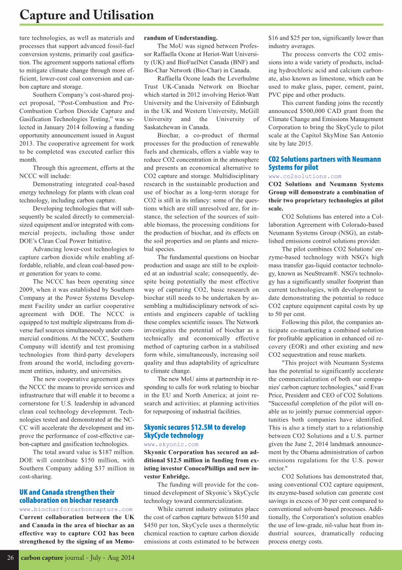
26 carbon capture journal - July - Aug 2014
Capture and Utilisation
ture technologies, as well as materials and
processes that support advanced fossil-fuel
conversion systems, primarily coal gasifica-
tion. The agreement supports national efforts
to mitigate climate change through more ef-
ficient, lower-cost coal conversion and car-
bon capture and storage.
Southern Company’s cost-shared proj-
ect proposal, “Post-Combustion and Pre-
Combustion Carbon Dioxide Capture and
Gasification Technologies Testing,” was se-
lected in January 2014 following a funding
opportunity announcement issued in August
2013. The cooperative agreement for work
to be completed was executed earlier this
month.
Through this agreement, efforts at the
NCCC will include:
Demonstrating integrated coal-based
energy technology for plants with clean coal
technology, including carbon capture.
Developing technologies that will sub-
sequently be scaled directly to commercial-
sized equipment and/or integrated with com-
mercial projects, including those under
DOE’s Clean Coal Power Initiative.
Advancing lower-cost technologies to
capture carbon dioxide while enabling af-
fordable, reliable, and clean coal-based pow-
er generation for years to come.
The NCCC has been operating since
2009, when it was established by Southern
Company at the Power Systems Develop-
ment Facility under an earlier cooperative
agreement with DOE. The NCCC is
equipped to test multiple slipstreams from di-
verse fuel sources simultaneously under com-
mercial conditions. At the NCCC, Southern
Company will identify and test promising
technologies from third-party developers
from around the world, including govern-
ment entities, industry, and universities.
The new cooperative agreement gives
the NCCC the means to provide services and
infrastructure that will enable it to become a
cornerstone for U.S. leadership in advanced
clean coal technology development. Tech-
nologies tested and demonstrated at the NC-
CC will accelerate the development and im-
prove the performance of cost-effective car-
bon-capture and gasification technologies.
The total award value is $187 million.
DOE will contribute $150 million, with
Southern Company adding $37 million in
cost-sharing.
UK and Canada strengthen theircollaboration on biochar researchwww.biocharforcarboncapture.com Current collaboration between the UK
and Canada in the area of biochar as an
effective way to capture CO2 has been
strengthened by the signing of an Memo-
$16 and $25 per ton, significantly lower than
industry averages.
The process converts the CO2 emis-
sions into a wide variety of products, includ-
ing hydrochloric acid and calcium carbon-
ate, also known as limestone, which can be
used to make glass, paper, cement, paint,
PVC pipe and other products.
This current funding joins the recently
announced $500,000 CAD grant from the
Climate Change and Emissions Management
Corporation to bring the SkyCycle to pilot
scale at the Capitol SkyMine San Antonio
site by late 2015.
CO2 Solutions partners with NeumannSystems for pilot www.co2solutions.comCO2 Solutions and Neumann Systems
Group will demonstrate a combination of
their two proprietary technologies at pilot
scale.
CO2 Solutions has entered into a Col-
laboration Agreement with Colorado-based
Neumann Systems Group (NSG), an estab-
lished emissions control solutions provider.
The pilot combines CO2 Solutions' en-
zyme-based technology with NSG's high
mass transfer gas-liquid contactor technolo-
gy, known as NeuStream®. NSG's technolo-
gy has a significantly smaller footprint than
current technologies, with development to
date demonstrating the potential to reduce
CO2 capture equipment capital costs by up
to 50 per cent.
Following this pilot, the companies an-
ticipate co-marketing a combined solution
for profitable application in enhanced oil re-
covery (EOR) and other existing and new
CO2 sequestration and reuse markets.
"This project with Neumann Systems
has the potential to significantly accelerate
the commercialization of both our compa-
nies' carbon capture technologies," said Evan
Price, President and CEO of CO2 Solutions.
"Successful completion of the pilot will en-
able us to jointly pursue commercial oppor-
tunities both companies have identified.
This is also a timely start to a relationship
between CO2 Solutions and a U.S. partner
given the June 2, 2014 landmark announce-
ment by the Obama administration of carbon
emissions regulations for the U.S. power
sector."
CO2 Solutions has demonstrated that,
using conventional CO2 capture equipment,
its enzyme-based solution can generate cost
savings in excess of 30 per cent compared to
conventional solvent-based processes. Addi-
tionally, the Corporation's solution enables
the use of low-grade, nil-value heat from in-
dustrial sources, dramatically reducing
process energy costs.
randum of Understanding.
The MoU was signed between Profes-
sor Raffaella Ocone at Heriot-Watt Universi-
ty (UK) and BioFuelNet Canada (BNF) and
Bio-Char Network (Bio-Char) in Canada.
Raffaella Ocone leads the Leverhulme
Trust UK-Canada Network on Biochar
which started in 2012 involving Heriot-Watt
University and the University of Edinburgh
in the UK and Western University, McGill
University and the University of
Saskatchewan in Canada.
Biochar, a co-product of thermal
processes for the production of renewable
fuels and chemicals, offers a viable way to
reduce CO2 concentration in the atmosphere
and presents an economical alternative to
CO2 capture and storage. Multidisciplinary
research in the sustainable production and
use of biochar as a long-term storage for
CO2 is still in its infancy: some of the ques-
tions which are still unresolved are, for in-
stance, the selection of the sources of suit-
able biomass, the processing conditions for
the production of biochar, and its effects on
the soil properties and on plants and micro-
bial species.
The fundamental questions on biochar
production and usage are still to be exploit-
ed at an industrial scale; consequently, de-
spite being potentially the most effective
way of capturing CO2, basic research on
biochar still needs to be undertaken by as-
sembling a multidisciplinary network of sci-
entists and engineers capable of tackling
these complex scientific issues. The Network
investigates the potential of biochar as a
technically and economically effective
method of capturing carbon in a stabilised
form while, simultaneously, increasing soil
quality and thus adaptability of agriculture
to climate change.
The new MoU aims at partnership in re-
sponding to calls for work relating to biochar
in the EU and North America; at joint re-
search and activities; at planning activities
for repurposing of industrial facilities.
Skyonic secures $12.5M to developSkyCycle technology www.skyonic.comSkyonic Corporation has secured an ad-
ditional $12.5 million in funding from ex-
isting investor ConocoPhillips and new in-
vestor Enbridge.
The funding will provide for the con-
tinued development of Skyonic’s SkyCycle
technology toward commercialization.
While current industry estimates place
the cost of carbon capture between $150 and
$450 per ton, SkyCycle uses a thermolytic
chemical reaction to capture carbon dioxide
emissions at costs estimated to be between
CCJ40_Layout 1 29/06/2014 15:32 Page 26

July - Aug 2014 - carbon capture journal 27
Transport and Storage
The Wyoming Rock Springs Uplift could po-
tentially store 14 to 17 billion metric tons of
carbon dioxide (CO2), according to results
from a Department of Energy-sponsored
study. This is equal to 250 to 300 years’
worth of CO2 emissions produced by
Wyoming’s coal-fired power plants and oth-
er large regional anthropogenic CO2 sources
at current emission levels.
The project team – led by the Universi-
ty of Wyoming’s Carbon Management Insti-
tute and sponsored by the Office of Fossil
Energy’s National Energy Technology Lab-
oratory – gathered geologic, hydrologic and
geochemical data from a 12,810-foot-deep
stratigraphic test well drilled to evaluate the
area’s potential as a long-term, high-volume
storage site for CO2.
The Rock Springs Uplift (RSU), a geo-
logic feature in southwestern Wyoming, was
found to have the sought-after combination
of ideal geological characteristics for carbon
storage, and proximity to some of
Wyoming’s largest sources of anthropogenic
CO2 emissions.
To evaluate the site’s potential for CO2
storage, the project team performed digital
imaging of a core sample to learn about the
formation’s grain size, mineralogy, facies
distribution, and porosity. In addition, the
team studied a comprehensive set of geo-
physical data from the test well, focusing on
two potential CO2 storage reservoirs — the
Madison Limestone and the Weber/Tensleep
Sandstone — and the overlying formations
that would trap the CO2 at depth.
The researchers discovered that, along
with the promise of a prime CO2 storage
space, the deep saline waters of the Rock
Springs Uplift contain high, commercially
viable concentrations of lithium: ~190 parts
per million for the Weber/Tensleep Sand-
stone, and ~130 parts per million for the
Madison Limestone.
For every 1 million metric tons of CO2
stored, approximately 250 metric tons of
lithium carbonate, with an approximate mar-
ket value of $1.6 million, could be recovered
from processed brine. Lithium, which is used
in batteries and other electronics applica-
tions, has become vital as many nations tran-
sition to greener technologies. The recovered
lithium could generate revenue to offset the
cost of CO2 storage and help reduce the need
for lithium import.
In addition to the testing completed
within the characterization well, and on sam-
ples removed from it, the project team per-
formed a three-dimensional seismic survey
of a 25-square-mile area around the test site.
The seismic data allowed the researchers to
extrapolate the geologic properties measured
in the well — such as porosity, permeability,
and fluid saturation — to the rocks through-
out the two storage reservoirs and confining
formations.
This made it possible to build realistic
three-dimensional geologic models of these
formations. Combining this with information
gathered in the lab from the core samples,
the researchers developed realistic assess-
ments of how injected CO2 would behave in
the storage reservoirs, which in turn yielded
greatly improved CO2 storage capacity esti-
mates.
Carbon storage potential in WyomingA geological feature in Wyoming could store up to 300 years of the region's CO2 emissions, a studyfinds.
Cross-section of Moxa Arch-Rock Springs Uplift in Southwest Wyoming
Project activityThe overall project goal is to characterize the RSU and Moxa Arch deep saline reservoirs
for potential commercial development. The University of Wyoming and partners are ac-
complishing this through:
• Acquiring new geophysical data from the RSU to complement existing Moxa Arch
data.
• Drilling and installing a 12,000 foot deep stratigraphic test well in the RSU. The
drilling site is located near PacifiCorp's 2,200 megawatt Jim Bridger coal-fired
power plant.
• Acquiring wireline logs, core, cuttings, fluid samples, and a baseline microseismic
signature from the RSU well.
• Performing microfrac tests of the primary seal (Dinwoody Shale) and two target
storage reservoirs.
• Conducting a 3-D seismic survey and an electromagnetic survey over a 25-square
mile area surrounding the characterization well site.
• Developing a geologic model and performing numerical simulations of different
CO2 injection/storage scenarios in the Madison Limestone formation to predict
reservoir pressures and the displacement of formation saline fluids.
• Designing a complete management and treatment facility for displaced water to
maintain acceptable reservoir pressures, obtain usable water, and extract valuable
minerals (including lithium) from formation fluids.
More informationwww.netl.doe.gov/research
CCJ40_Layout 1 29/06/2014 15:32 Page 27

28 carbon capture journal - July - Aug 2014
Transport and Storage
Big Sky Carbon Sequestration Partnershipdrilling progressThe BSCSP field team has made substantial progress on the monitoring well since drilling began in May.
The Kevin Dome Carbon Storage project
reached an important milestone on Tuesday,
April 29, as ground was broken at the loca-
tion where the first production well will be
drilled, near the town of Oilmont in north-
central Montana.
The production well will be used to
extract naturally-occurring carbon dioxide
(CO2) from underground. It will be ~3,800
feet deep and take approximately 3 weeks
to drill. The team will also be logging and
coring this well. Researchers will test the
CO2 for its chemical composition and to
measure its “producibility” (for example,
how much is available and can it be consis-
tently extracted).
Over five days, the team drilled the
main hole down to a depth of 3,661 feet, the
target destination for extracting the first
core samples.
The “coring” process involves extract-
ing long cylinders of rock, which are stud-
ied for their geologic properties. The first
core was a 30 foot sample from the Potlatch
Formation, which consists of dense, anhy-
drite rock. This layer will serve as a second-
ary layer of cap rock above the CO2 injec-
tion zone.
From there, the team drilled ahead ap-
proximately 200 feet to reach another sec-
tion targeted for more extensive coring.
Starting at a depth of 3,904 feet, the team
cored a continuous section of 240 feet. The
process, which took three full days to com-
plete, was conducted by extracting four
samples, each in 60 foot core barrels.
By capturing samples from such a long
segment of the well, researchers will be
able to carefully analyze the complex geol-
ogy of the carbon dioxide (CO2) injection
zone, which includes layers of cap rock as
well as zones of high porosity and perme-
ability. This will help BSCSP pinpoint the
optimal for injection and monitoring activi-
ties.
When the coring was complete, the
team continued drilling approximately 550
feet, reaching the total, final depth of 4,700
feet on May 28. With the primary drilling
finished, the next tasks on this well will in-
clude logging (a measurement process), lin-
ing the hole with pipe, and cementing the
well surfaces.
Drilling the monitoring wellOn the weekend of May 17-18, the drilling
rig was moved to a new site, to begin work
on drilling the second well of the project.
This well will be used for geochemical
monitoring throughout the project. Located
near the proposed carbon dioxide (CO2) in-
jection area, the well will allow scientists
to take samples and conduct testing in or-
der to track the underground movement of
CO2.
On the morning of Monday, May 19,
the drilling team “spudded” or began
drilling the well. By the end of the day, they
had drilled and set surface casing of the sur-
face hole, which has a depth of 272 feet.
This well will take approximately two
weeks to drill and have a total depth of
4,700 feet. The team will also be logging
and coring this well.
Before the CO2 injection process be-
gins, the team will install additional moni-
toring wells in the project area to facilitate
comprehensive monitoring.
Logging the monitoring wellAfter the drilling of the main hole for the
monitoring well was finished, the team be-
gan the logging process, which allows them
to collect a wide range of geologic meas-
urements and data from the underground
layers exposed by the open hole.
Logging involves lowering advanced
measurement tools to the bottom of the
well. The tools collect the measurements
and data as they are pulled up slowly
through the length of the well hole. The
team monitors the logging process and the
incoming data in real time from a large ve-
hicle at the well site, which is equipped as
a mobile laboratory.
Through a suite of logs, the team can
collect valuable information such as the
depth and lithology (rock type) of each for-
mation, the porosity of rocks that are filled
with gas or liquid, the size and connectivity
of rock pores, the existence of fractures,
and other geologic properties, all of which
will guide drilling, injection and monitor-
ing activities throughout the life of the proj-
ect.
To collect all the data of interest, the
team completed three logging “passes” –
trips in and out of the hole with the equip-
ment. The process was conducted over a 24
hour period on May 28th and 29th. The da-
ta has been synthesized into well logs –
long, color coded graphs that display all the
collected readings and measurements, cor-
related to the well depths.
When the logging was complete, the
drill team cased the well by inserting and
connecting pipe (one joint at a time) down
the length of the hole. The well was then
cemented through a two-stage cement
process, first cementing the lower section
(from 4,700 feet deep to 2,390 feet), fol-
lowed by the upper section (from 2,390 feet
to the surface). Work on the monitoring
well was wrapped up successfully on the
evening of May 30th, and the drilling rig
was moved off the site.
Background Water SamplingThe BSCSP Surface Water Monitoring
Team returned to the Kevin Dome project
site recently to conduct a second round of
fieldwork. The team – led by Laura Dobeck
(Montana State University), Travis McLing
(Idaho National Lab), and Martin Stute
(Barnard College, Columbia University) –
collected surface water and groundwater
samples from sites across the project area,
including ponds, reservoirs, and shallow
water wells.
Similar to the first round of fieldwork
in the fall of 2013, these water samples will
undergo laboratory analysis and provide a
critical set of baseline data on the current
chemical composition and general water
quality of shallow subsurface and surface
waters in the project area.
This baseline information will be com-
pared to future water samples collected dur-
ing and after the carbon dioxide (CO2) in-
jection phase of the project. These compar-
isons will allow BSCSP scientists to pro-
vide assurance that water resources in the
area are not being damaged.
More informationwww.bigskyco2.org
CCJ40_Layout 1 29/06/2014 15:32 Page 28

July - Aug 2014 - carbon capture journal 29
Transport and Storage
Scottish and Cypriot scientists join tostudy CO2 storage in Mediterranean www.sccs.org.ukScientists from Scotland and Cyprus have
formed a research partnership that could
open up a new frontier for the storage of
CO2 in the eastern Mediterranean.
The agreement between the University
of Nicosia’s Centre for Green Development
and Energy Policy (CGD) and Scottish Car-
bon Capture & Storage (SCCS) will seek
funding for researchers from the far reaches
of the European Union to work together to
identify likely geological CO2 storage sites
beneath the Mediterranean Sea to the south
of Cyprus.
Using methodology developed in pre-
vious SCCS projects to assess CO2 storage
capacity in the North Sea, the scientists will
study seismic data and other information to
build a picture of storage sites – including
depleted oil and gas reservoirs and saline
aquifers – which could boost Cyprus’s ca-
pacity for tackling carbon emissions.
SCCS Director, Professor Stuart Hasze-
dine, announced the Memorandum of Un-
derstanding between SCCS and CGD at the
All-Energy 2014 conference in Aberdeen.
Prof Haszeldine said: “Our research
agreement with the University of Nicosia’s
Centre for Green Development is an excit-
ing development for SCCS. It brings togeth-
er expertise from both research groups for
the shared goal of opening up new opportu-
nities for CO2 storage, as a fledgling hydro-
carbons industry in Cyprus plans its future.
It will also provide excellent training oppor-
tunities for staff and students.”
Study shows Scotland ready for CCShubwww.element-energy.co.ukA study by Element Energy has shown
that all the components are either in place,
or can be readily developed, for Scotland
to become a CCS hub.
Element Energy Ltd, working with
partners SCCS, AMEC, and Dundas Con-
sultants, recently completed the analysis in-
to the development of CCS in the UK on be-
half of Scottish Enterprise.
The report examines a wide range of
scenarios for how CCS might develop and
uses these to develop blueprints and detailed
business plans for how to deliver CCS at
least cost, least risk, and with maximum
flexibility.
The report details how the combination
of Carbon Capture and Storage with En-
hanced Oil Recovery in the Central North
Sea provides an excellent platform to
achieve multiple benefits:
- Support the decarbonisation of the
economy in Scotland, the UK and North
West Europe, with potential for storing up to
1,700 million tonnes of UK and European
CO2 over the period to 2050, helping us to
meet the challenge of climate change.
- This can be accompanied by the eco-
nomic production of up to 1.4 billion addi-
tional barrels of oil in the North Sea, extend-
ing the life of the oil industry in the UK,
Norway and Denmark, and bringing in £10
bn in discounted revenue, and associated
benefits in balance of trade, jobs, and energy
security.
- Boost the economy - the potential
gross value added to the Scottish economy
from supporting infrastructure alone would
be up to ca. £7 billion over the peri-
od to 2050.
- Reduce the costs of storage directly,
leave a legacy infrastructure that could sup-
port decades of CCS activity, and generate
tax revenues that could offset the costs of di-
rect and indirect subsidies for CCS.
- Create cumulatively 44,000 person-
years of employment in Scotland in the peri-
od to 2050.
The study has illustrated that all the
components are either in place, or can be
readily developed, for Scotland to become a
CCS hub, supporting UK and European CCS
deployment.
The CNS has by far the UK's largest va-
riety of stakeholder interests, legacy facili-
ties (pipelines, platforms and wells), poten-
tial physical and commercial / regulatory
configurations for CCS development. This
leads to a wealth of opportunity for estab-
lished North Sea operators as well as new
entrants. That demands leadership and flexi-
bility, which Scotland is ready and willing
to deliver.
The report provides a series of recom-
mendations for Scotland if it wishes to be a
European leader in CCS. Efforts to champi-
on CCS projects, and develop infrastructure
for EOR, power and industry in the UK and
Europe should be stepped up immediately
and continue during the 2010s on the follow-
ing themes:
- Support for early CCS demonstration
in Scotland
- Maximising the UK and European
market for CCS in the 2010s and 2020s
- Supporting infrastructure that targets
the CNS
- Improving CCS readiness and opti-
mising infrastructure
- Improving the commercial attractive-
ness of CO2 transport, storage and EOR
ETI to develop CCS marine monitoringsystem www.eti.co.ukThe Energy Technologies Institute (ETI)
is developing a monitoring system using
marine robotics to provide assurance that
carbon dioxide stored deep below the
seabed in CCS sites is secure.
The project will be commissioned and
funded by the ETI and will seek to develop
a monitoring system which could be de-
ployed using static monitoring equipment
and marine robotics such as autonomous un-
derwater vehicles (AUVs).
The project will be led by Fugro GEOS
in collaboration with Sonardyne, the National
Oceanography Centre (NOC) and the British
Geological Survey (both part of NERC), Ply-
mouth Marine Laboratory and the University
of Southampton. The ETI is to invest £1m in
the first phase of the project.
The ETI is to invest £1m in the first
phase of the project. The first 12 months will
see the economic and technological plans for
the monitoring system developed.
Although there are existing technology
components which can detect CO2 in a ma-
rine environment, there are no integrated,
cost-effective and commercially available
systems which can currently reliably record
and report anomalies in the level of CO2 in
the sea above a large store. The need to in-
troduce capability for the robust monitoring
of underground CO2 storage sites is in re-
sponse to legislation such as the European
Union’s directive on CO2 storage. This
states that any storage operator must moni-
tor for potential leaks and examine whether
any leak is damaging to the environment or
human health.
Current research and evidence shows
that leakage is highly unlikely. However if
CO2 did escape, it would be difficult to pre-
dict with certainty exactly where it would
reach the seabed. This is where mobile au-
tonomous robots are very useful, patrolling
over large areas at relatively low cost.
Robotics and Autonomous Systems
was identified last year by the Minister for
Universities and Science, David Willetts, as
one of the 'Eight Great Technologies' that
will propel the UK to future growth, and re-
ceived a funding boost to bring the research
base and industry together.
Den Gammer, ETI Strategy Manager
for CCS added: “Progress on the develop-
ment of a cost-effective, reliable monitoring
system for the marine environment above
CO2 storage complexes is another key step
in the process of building confidence in a
new CCS industry in the UK.”
Transport and storage news
CCJ40_Layout 1 29/06/2014 15:32 Page 29
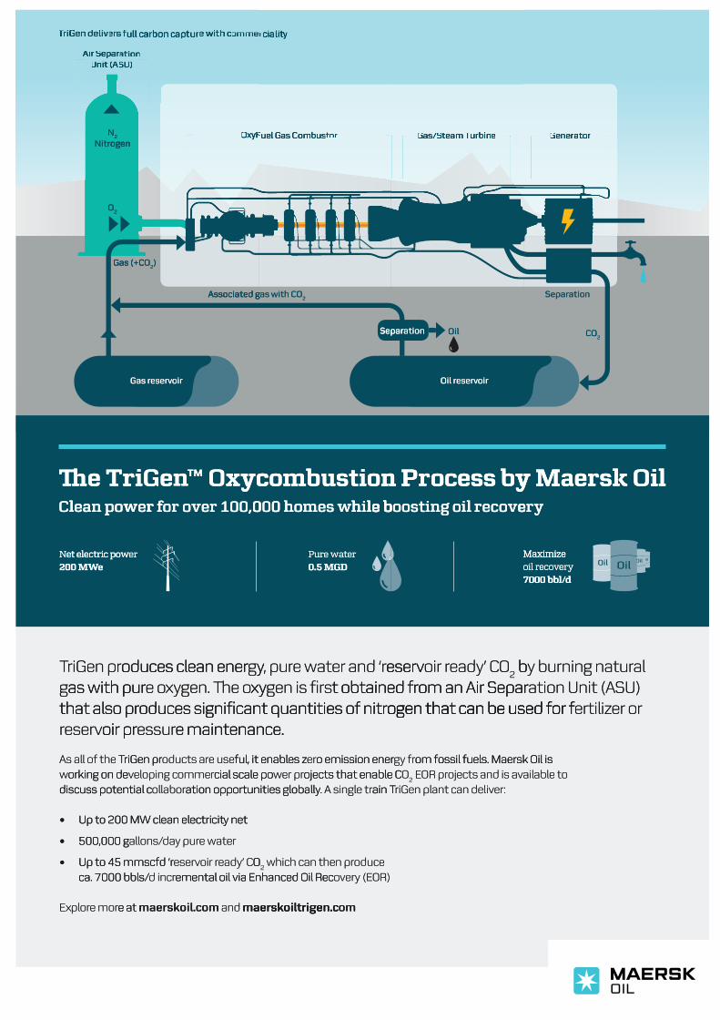
Separation
Gas reservoir Oil reservoir
Separation
CO2
Gas (+CO2)
Oil
Associated gas with CO2
Air SeparationUnit (ASU)
OxyFuel Gas Combustor Gas/Steam Turbine Generator
O2
N2
Nitrogen
TriGen delivers full carbon capture with commerciali�
�e TriGen™ Oxycombustion Process by Maersk OilClean power for over 100,000 homes while boosting oil recovery
Pure water0.5 MGD
Net electric power200 MWe
Maximize oil recovery7000 bbl/d
TriGen produces clean energy, pure water and ‘reservoir ready’ CO2 by burning natural
gas with pure oxygen. �e oxygen is first obtained from an Air Separation Unit (ASU) that also produces significant quantities of nitrogen that can be used for fertilizer or reservoir pressure maintenance.
As all of the TriGen products are useful, it enables zero emission energy from fossil fuels. Maersk Oil is working on developing commercial scale power projects that enable CO
2 EOR projects and is available to
discuss potential collaboration opportunities globally. A single train TriGen plant can deliver:
• Up to 200 MW clean electrici� net
• 500,000 gallons/day pure water
• Up to 45 mmscfd ‘reservoir ready’ CO2 which can then produce
ca. 7000 bbls/d incremental oil via Enhanced Oil Recovery (EOR) Explore more at maerskoil.com and maerskoiltrigen.com
N
O2
2
ogenNitr
ogen
Gas (+C
OGas (+C2)
Associated g
O
Separ
as with CAssociated g2
ation OilSepar
ationSepar
CO2
re T�l
c
oireservGas r
yx™ Onn™eGirr f
n Poitsubmoce blh0 h
y M
oireservOil r
s bsecorn Pl re b
ik Osreay M
li
won paelC
et electric powNe200 MWWe
0,00r 1evr oor ffoew
eret electric pow
e blihs wemo0 h00
tere waPur0.5 MGD
evoecl rig onitsooe b
Maximize
yre
Maximize eryecovoil r
d7000 bbl//d
oduces clean enerriGen prTTras with purg
that also proir preservr
riGen prAs all of the T
gyoduces clean enerxygen. �e oxye oas with pur
oduces significant quantities of nitrthat also pre maintenance.essuroir pr
ful, it enables ze useoducts arriGen pr
eserve water and ‘r, puryy,t obtained frgen is firsxy
ogen that can be used for foduces significant quantities of nitre maintenance.
o emission enererful, it enables z
Oeady’ Coir reserv2 b
om an Air Separt obtained frogen that can be used for f
om fossil fuels. Maersk Oil is gy fro emission ener
aly burning natur bSU)ation Unit (Aom an Air Separ
er orertilizogen that can be used for f
om fossil fuels. Maersk Oil is
orking on dewdiscuss potential c
• Up to 200 MW clean electrici� net
• 500,000 g
• Up to 45 mmscfd ‘rca. 7000 bbls/
cial scale poommereloping cvorking on deation opportunities globallyollabordiscuss potential c
Up to 200 MW clean electrici� net
e watery purdaallons/500,000 g
Oeady’ Coir reservUp to 45 mmscfd ‘remental oil via Enhanced Oil Recd incrca. 7000 bbls/
ojects that enable Cer prwcial scale poain T. A single tration opportunities globally
O2
oduce which can then prOR)ery (Evoemental oil via Enhanced Oil Rec
Oojects that enable C2
vojects and is aOR pr Eer:riGen plant can delivain T
ailable to
e at e morplorEx
e at ommaerskoil.c and maerskoiltrigen.c
ommaerskoiltrigen.c
CCJ40_Layout 1 29/06/2014 15:32 Page 30