Embed Size (px)
DESCRIPTION
welding
Citation preview
156-s | MAY 1999
RE
SE
AR
CH
/DE
VE
LO
PM
EN
T/R
ES
EA
RC
H/D
EV
EL
OP
ME
NT
/RE
SE
AR
CH
/DE
VE
LO
PM
EN
T/R
ES
EA
RC
H/D
EV
EL
OP
ME
NT
ABSTRACT. Welding thin-plate panelstructures often results in warping of thepanels. Several mitigation methods, in-cluding preheating and prestressing theplates during assembly, have been inves-tigated and used by some fabricators.This paper studies the distortion mecha-nisms and the effect of welding sequenceon panel distortion. In this study, distor-tion behaviors, including local platebending and buckling as well as globalgirder bending, were investigated usingthe finite element method. It was foundthat buckling doesn’t occur in structureswith a skin-plate thickness of more than1.6 mm unless the stiffening girder bendsexcessively. Warping is primarily causedby angular bending of the plate itself. Thejoint rigidity method (JRM) was found tobe effective in determining the optimumwelding sequence for minimum panelwarping.
Introduction
Warping is a common problem expe-rienced in the welding fabrication of thin-walled panel structures. Several factorsthat influence distortion control strategymay be categorized into design-relatedand process-related variables. Significantdesign-related variables include weldjoint details, plate thickness, thicknesstransition if the joint consists of plates ofdifferent thickness, stiffener spacing,number of attachments, corrugated con-struction, mechanical restraint condi-tions, assembly sequence and overallconstruction planning. Important vari-
ables are welding process, heat input,travel speed and welding sequence.
In principle, welding distortion con-trol practices for thin-wall panel struc-tures may be classified as follows:
Use design practices that make dis-tortion-free panels easier to produce.These design practices include choosingplates with appropriate thickness, reduc-ing stiffener spacing, using a bevel T-stiff-ener web, optimizing assembly sequenc-ing, properly applying jigs and fixturesand using the egg-crate constructiontechnique (Ref. 1).
Better control of certain welding vari-ables will eliminate the conditions thatpromote distortion. This includes reduc-ing fillet weld size and length, includingtack welds; using high-speed welding;using a low heat input welding process;using intermittent welds; using a backsteptechnique; and balancing heat about theplate’s neutral axis in butt joint welding.
Incorporate a welding QC program.This program should include personneltraining on general quality control prac-tice in order to reduce distortion through
awareness, using flatter plates andstraighter stiffeners to control the initialconditions, reducing weld size by im-proving joint fitup and eliminating struc-turally irrelevant rework.
The implementation of distortion mit-igation techniques during welding coun-teracts the effects of shrinkage duringcooling, which distorts the fabricatedstructure. These mitigation techniques in-clude controlled preheating, mechanicaltensioning, thermal tensioning, pre-bend-ing fillet joints, presetting butt joints andusing appropriate heat sinking arrange-ments. All these mitigation techniques areto balance weld shrinkage forces. Heatsinking also balances welding heat aboutthe neutral axis of the joint.
Some of the aforementioned distor-tion control methods may increase fabri-cation costs due to requirements for moreenergy, increased labor and potentiallyhigh-cost capital equipment. Somemethods may not be suitable for auto-mated welding or may reduce the as-sembly speed due to interruption fromfixtures or stiffener arrangements. De-pending on circumstances of the fabrica-tion environment and type of structures,different distortion control methods mayprovide more adequate solutions to cer-tain problems than others. Understand-ing their capability and limitation of allthese distortion control methods is criti-cal to a successful welding fabricationproject.
Literature Review
Warping of thin-walled panel struc-tures has been investigated with both ex-perimental and numerical methods usedby many researchers (Refs. 2–15). In the1950s, Watanabe and Satoh (Ref. 2) ob-
Welding Distortion of a Thin-Plate PanelStructure
BY C. L. TSAI, S. C. PARK AND W. T. CHENG
The effect of welding sequence on panel distortion is evaluated
KEY WORDS
DistortionThin Plate FEMFinite Element MethodAluminum PlateGas Metal ArcGMAWJoint RigidityBucklingC. L. TSAI and W. T. CHENG are with The
Ohio State University, Columbus, Ohio. S. C.PARK is with Hyundai Industrial Research In-stitute, Korea.
WELDING RESEARCH SUPPLEMENT | 157-s
RE
SE
AR
CH
/DE
VE
LO
PM
EN
T/R
ES
EA
RC
H/D
EV
EL
OP
ME
NT
/RE
SE
AR
CH
/DE
VE
LO
PM
EN
T/R
ES
EA
RC
H/D
EV
EL
OP
ME
NT
served bucking phenomenon in weldingof a thin mild steel plate. Masubuchi (Ref.3) later extended the work and observeda similar phenomenon. Both experimen-tal studies used bead-on-plate couponswith relatively long and narrow strips.
In the 1970s, Taniguchi (Ref. 4) inves-tigated angular bending of fillet-weldedaluminum panel structures using an inte-grated numerical and experimental ap-proach. A relationship was developedbetween angular changes and platethickness for various fillet sizes and spanwidths. Pattee (Ref. 5) conducted experi-ments to investigate buckling behaviorsof aluminum plates with differentboundary conditions. His experimentalwork reached similar conclusions.
In 1976, based on their comprehen-sive research results, Satoh and Terasaki(Ref. 6) proposed simple formulas thatcorrelate residual stress, angular bendingand transverse shrinkage to the weldingheat input for different materials, includ-ing mild steel, high-strength steel, 9% Ni
steel, Al 5083-O and stainless steel.Terai, et al. (Ref. 7), investigated sev-
eral mitigation methods to minimizewelding distortion in thin-plate panels forship superstructures. These methods in-cluded preheating, prestressing and pre-setting. Angular bending of the panelplates was reduced substantially whenthese mitigation methods were applied inwelding fabrication.
Penso (Ref. 8) conducted numericaland experimental investigations to ana-lyze bending distortion of a mild steelpanel structure. An engineering method,commonly referred to as the “inherentshrinkage method,” was used to deter-mine the distortion. The numerical re-sults were in good agreement with theexperimental results. This work furtheranalyzed the experimental panel struc-ture, investigated by Terai, et al. (Ref. 7),and verified the beneficial effect of pre-heating and prestressing on out-of-planedistortion of the panel.
For many years, researchers have
studied the predictive methods for weld-ing-induced distortions using the finiteelement method (FEM). Models with var-ious complexities were developed. Manycomplex models contributed to theknowledge of distortion, but might be im-practical for industrial applications dueto the required computational intensity.Simplified engineering approaches, suchas the inherent shrinkage model, havebeen studied. Daniewicz (Ref. 9) pre-sented a hybrid experimental and nu-merical approach to predict weld distor-tion of large offshore structures.Experimentally determined weld shrink-age values were implemented into thestructural FEM model to predict the struc-tural rigidity interaction and the finalequilibrium state, namely, distortion.
More recently, Michaleris and De-Biccari (Ref. 10) studied the numericalanalysis technique to predict welding-induced distortion in large and complexstructures. The technique combinedtwo-dimensional welding simulations
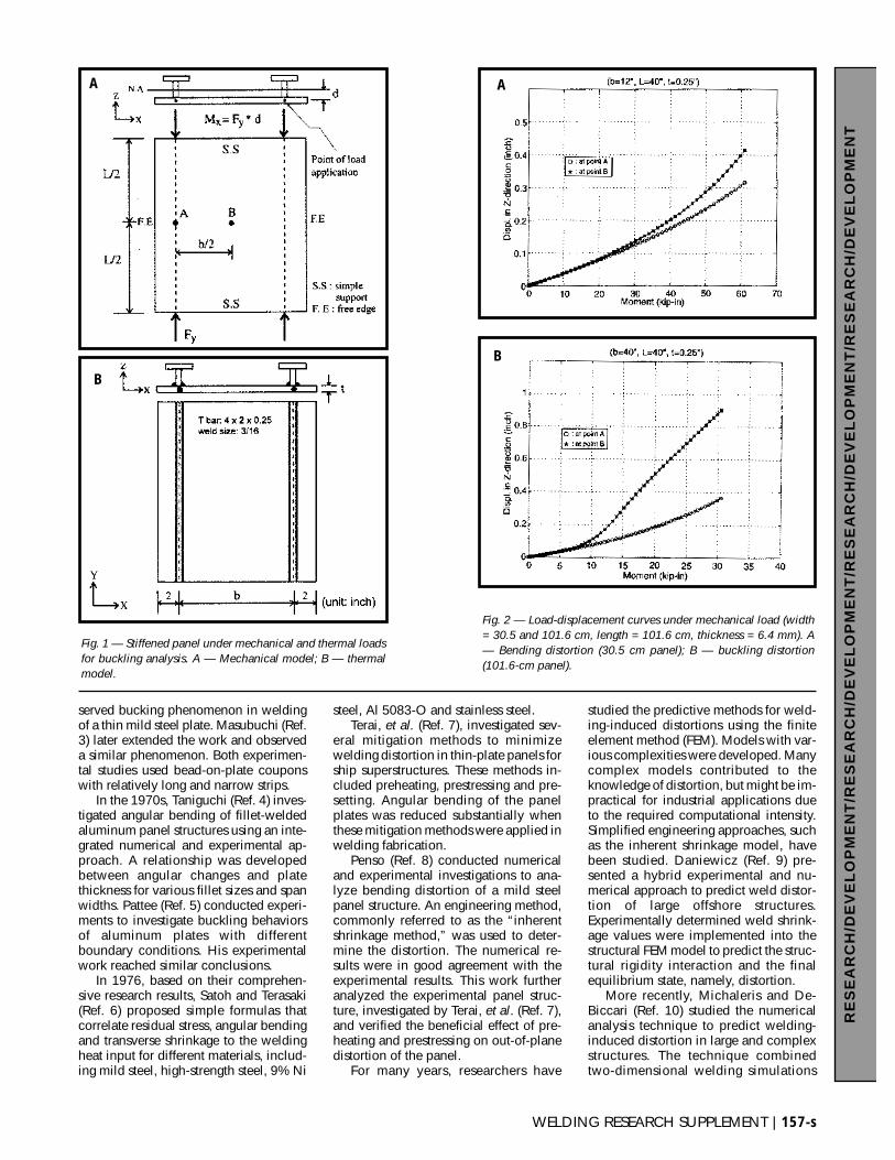
Fig. 1 — Stiffened panel under mechanical and thermal loadsfor buckling analysis. A — Mechanical model; B — thermalmodel.
A A
B
B
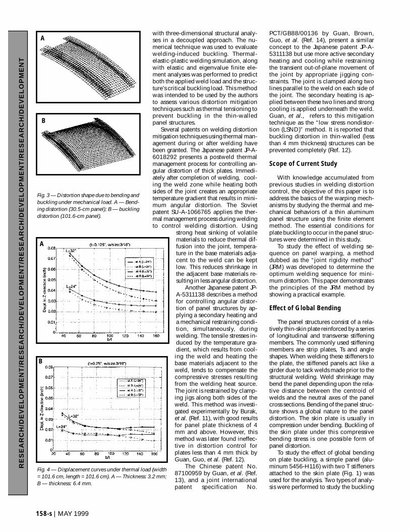
Fig. 2 — Load-displacement curves under mechanical load (width= 30.5 and 101.6 cm, length = 101.6 cm, thickness = 6.4 mm). A— Bending distortion (30.5 cm panel); B — buckling distortion(101.6-cm panel).
with three-dimensional structural analy-ses in a decoupled approach. The nu-merical technique was used to evaluatewelding-induced buckling. Thermal-elastic-plastic welding simulation, alongwith elastic and eigenvalue finite ele-ment analyses was performed to predictboth the applied weld load and the struc-ture’s critical buckling load. This methodwas intended to be used by the authorsto assess various distortion mitigationtechniques such as thermal tensioning toprevent buckling in the thin-walledpanel structures.
Several patents on welding distortionmitigation techniques using thermal man-agement during or after welding havebeen granted. The Japanese patent JP-A-6018292 presents a postweld thermalmanagement process for controlling an-gular distortion of thick plates. Immedi-ately after completion of welding, cool-ing the weld zone while heating bothsides of the joint creates an appropriatetemperature gradient that results in mini-mum angular distortion. The Sovietpatent SU-A-1066765 applies the ther-mal management process during weldingto control welding distortion. Using
strong heat sinking of volatilematerials to reduce thermal dif-fusion into the joint, tempera-ture in the base materials adja-cent to the weld can be keptlow. This reduces shrinkage inthe adjacent base materials re-sulting in less angular distortion.
Another Japanese patent JP-A-5311138 describes a methodfor controlling angular distor-tion of panel structures by ap-plying a secondary heating anda mechanical restraining condi-tion, simultaneously, duringwelding. The tensile stresses in-duced by the temperature gra-dient, which results from cool-ing the weld and heating thebase materials adjacent to theweld, tends to compensate thecompressive stresses resultingfrom the welding heat source.The joint is restrained by clamp-ing jigs along both sides of theweld. This method was investi-gated experimentally by Burak,et al. (Ref. 11), with good resultsfor panel plate thickness of 4mm and above. However, thismethod was later found ineffec-tive in distortion control forplates less than 4 mm thick byGuan, Guo, et al. (Ref. 12).
The Chinese patent No.87100959 by Guan, et al. (Ref.13), and a joint internationalpatent specification No.
PCT/GB88/00136 by Guan, Brown,Guo, et al. (Ref. 14), present a similarconcept to the Japanese patent JP-A-5311138 but use more active secondaryheating and cooling while restrainingthe transient out-of-plane movement ofthe joint by appropriate jigging con-straints. The joint is clamped along twolines parallel to the weld on each side ofthe joint. The secondary heating is ap-plied between these two lines and strongcooling is applied underneath the weld.Guan, et al., refers to this mitigationtechnique as the “low stress nondistor-tion (LSND)” method. It is reported thatbuckling distortion in thin-walled (lessthan 4 mm thickness) structures can beprevented completely (Ref. 12).
Scope of Current Study
With knowledge accumulated fromprevious studies in welding distortioncontrol, the objective of this paper is toaddress the basics of the warping mech-anisms by studying the thermal and me-chanical behaviors of a thin aluminumpanel structure using the finite elementmethod. The essential conditions forplate buckling to occur in the panel struc-tures were determined in this study.
To study the effect of welding se-quence on panel warping, a methoddubbed as the “joint rigidity method”(JRM) was developed to determine theoptimum welding sequence for mini-mum distortion. This paper demonstratesthe principles of the JRM method byshowing a practical example.
Effect of Global Bending
The panel structures consist of a rela-tively thin-skin plate reinforced by a seriesof longitudinal and transverse stiffeningmembers. The commonly used stiffeningmembers are strip plates, Ts and angleshapes. When welding these stiffeners tothe plate, the stiffened panels act like agirder due to tack welds made prior to thestructural welding. Weld shrinkage maybend the panel depending upon the rela-tive distance between the centroid ofwelds and the neutral axes of the panelcross sections. Bending of the panel struc-ture shows a global nature to the paneldistortion. The skin plate is usually incompression under bending. Buckling ofthe skin plate under this compressivebending stress is one possible form ofpanel distortion.
To study the effect of global bendingon plate buckling, a simple panel (alu-minum 5456-H116) with two T stiffenersattached to the skin plate (Fig. 1) wasused for the analysis. Two types of analy-sis were performed to study the buckling
158-s | MAY 1999
RE
SE
AR
CH
/DE
VE
LO
PM
EN
T/R
ES
EA
RC
H/D
EV
EL
OP
ME
NT
/RE
SE
AR
CH
/DE
VE
LO
PM
EN
T/R
ES
EA
RC
H/D
EV
EL
OP
ME
NT
A
B
B
A
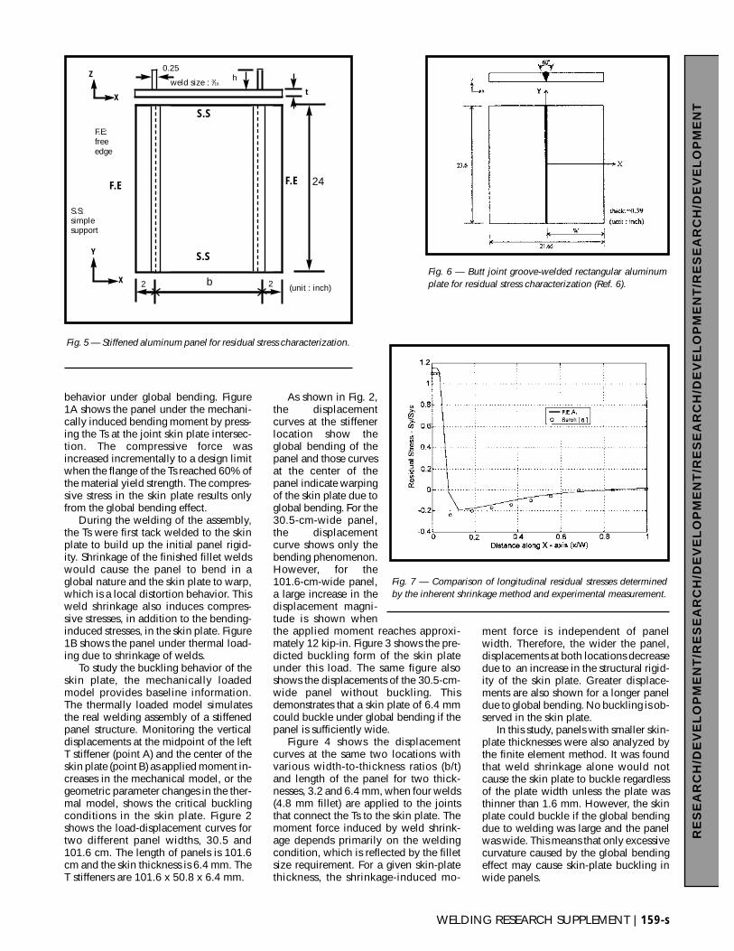
Fig. 3 — Distortion shape due to bending andbuckling under mechanical load. A — Bend-ing distortion (30.5-cm panel); B — bucklingdistortion (101.6-cm panel).
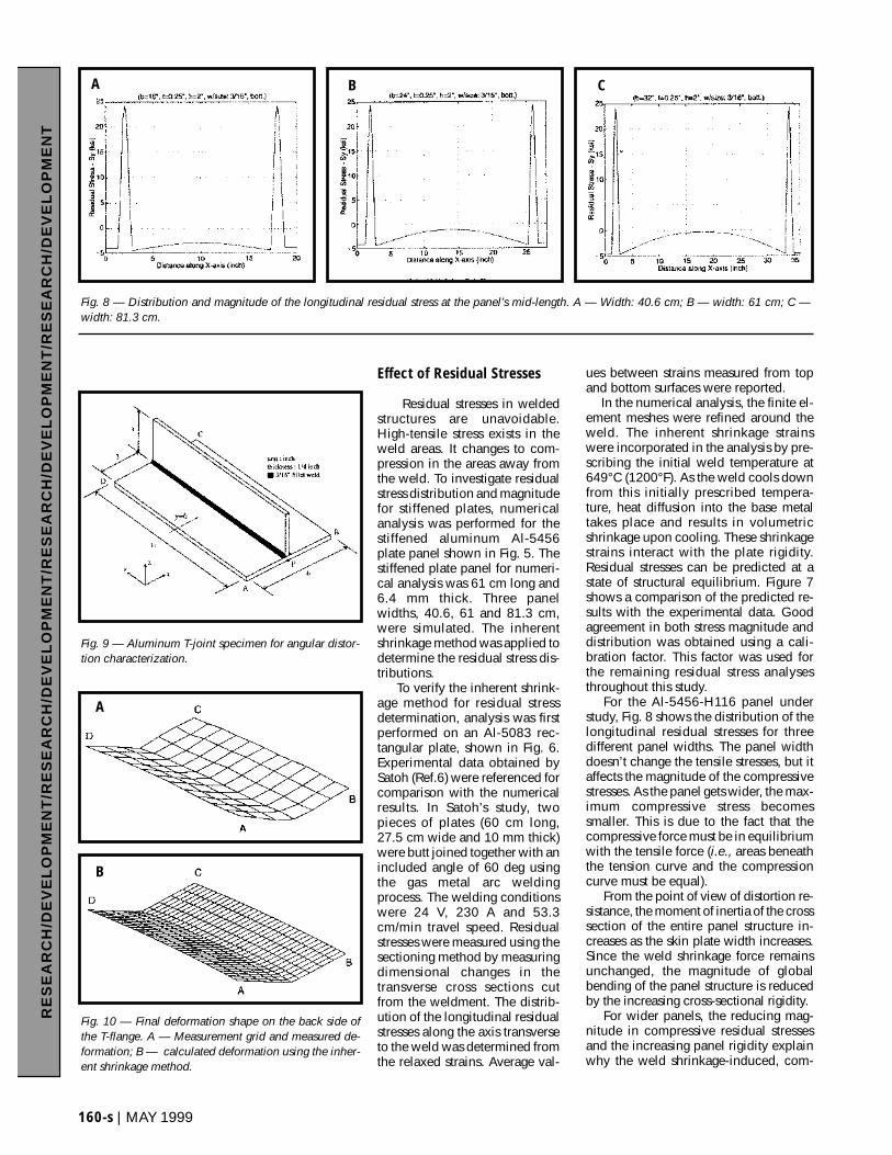
Fig. 4 — Displacement curves under thermal load (width= 101.6 cm, length = 101.6 cm). A — Thickness: 3.2 mm;B — thickness: 6.4 mm.
WELDING RESEARCH SUPPLEMENT | 159-s
RE
SE
AR
CH
/DE
VE
LO
PM
EN
T/R
ES
EA
RC
H/D
EV
EL
OP
ME
NT
/RE
SE
AR
CH
/DE
VE
LO
PM
EN
T/R
ES
EA
RC
H/D
EV
EL
OP
ME
NT
behavior under global bending. Figure1A shows the panel under the mechani-cally induced bending moment by press-ing the Ts at the joint skin plate intersec-tion. The compressive force wasincreased incrementally to a design limitwhen the flange of the Ts reached 60% ofthe material yield strength. The compres-sive stress in the skin plate results onlyfrom the global bending effect.
During the welding of the assembly,the Ts were first tack welded to the skinplate to build up the initial panel rigid-ity. Shrinkage of the finished fillet weldswould cause the panel to bend in aglobal nature and the skin plate to warp,which is a local distortion behavior. Thisweld shrinkage also induces compres-sive stresses, in addition to the bending-induced stresses, in the skin plate. Figure1B shows the panel under thermal load-ing due to shrinkage of welds.
To study the buckling behavior of theskin plate, the mechanically loadedmodel provides baseline information.The thermally loaded model simulatesthe real welding assembly of a stiffenedpanel structure. Monitoring the verticaldisplacements at the midpoint of the leftT stiffener (point A) and the center of theskin plate (point B) as applied moment in-creases in the mechanical model, or thegeometric parameter changes in the ther-mal model, shows the critical bucklingconditions in the skin plate. Figure 2shows the load-displacement curves fortwo different panel widths, 30.5 and101.6 cm. The length of panels is 101.6cm and the skin thickness is 6.4 mm. TheT stiffeners are 101.6 x 50.8 x 6.4 mm.
As shown in Fig. 2,the displacementcurves at the stiffenerlocation show theglobal bending of thepanel and those curvesat the center of thepanel indicate warpingof the skin plate due toglobal bending. For the30.5-cm-wide panel,the displacementcurve shows only thebending phenomenon.However, for the101.6-cm-wide panel,a large increase in thedisplacement magni-tude is shown whenthe applied moment reaches approxi-mately 12 kip-in. Figure 3 shows the pre-dicted buckling form of the skin plateunder this load. The same figure alsoshows the displacements of the 30.5-cm-wide panel without buckling. Thisdemonstrates that a skin plate of 6.4 mmcould buckle under global bending if thepanel is sufficiently wide.
Figure 4 shows the displacementcurves at the same two locations withvarious width-to-thickness ratios (b/t)and length of the panel for two thick-nesses, 3.2 and 6.4 mm, when four welds(4.8 mm fillet) are applied to the jointsthat connect the Ts to the skin plate. Themoment force induced by weld shrink-age depends primarily on the weldingcondition, which is reflected by the filletsize requirement. For a given skin-platethickness, the shrinkage-induced mo-
ment force is independent of panelwidth. Therefore, the wider the panel,displacements at both locations decreasedue to an increase in the structural rigid-ity of the skin plate. Greater displace-ments are also shown for a longer paneldue to global bending. No buckling is ob-served in the skin plate.
In this study, panels with smaller skin-plate thicknesses were also analyzed bythe finite element method. It was foundthat weld shrinkage alone would notcause the skin plate to buckle regardlessof the plate width unless the plate wasthinner than 1.6 mm. However, the skinplate could buckle if the global bendingdue to welding was large and the panelwas wide. This means that only excessivecurvature caused by the global bendingeffect may cause skin-plate buckling inwide panels.
Fig. 5 — Stiffened aluminum panel for residual stress characterization.
Fig. 6 — Butt joint groove-welded rectangular aluminumplate for residual stress characterization (Ref. 6).
Fig. 7 — Comparison of longitudinal residual stresses determinedby the inherent shrinkage method and experimental measurement.
(unit : inch)
F.E
S.S
S.S
F.E
F.E:freeedge
24
22
0.25
X
X
h
t
Y
Z
b
S.S:simplesupport
weld size : 3⁄16
Effect of Residual Stresses
Residual stresses in weldedstructures are unavoidable.High-tensile stress exists in theweld areas. It changes to com-pression in the areas away fromthe weld. To investigate residualstress distribution and magnitudefor stiffened plates, numericalanalysis was performed for thestiffened aluminum Al-5456plate panel shown in Fig. 5. Thestiffened plate panel for numeri-cal analysis was 61 cm long and6.4 mm thick. Three panelwidths, 40.6, 61 and 81.3 cm,were simulated. The inherentshrinkage method was applied todetermine the residual stress dis-tributions.
To verify the inherent shrink-age method for residual stressdetermination, analysis was firstperformed on an Al-5083 rec-tangular plate, shown in Fig. 6.Experimental data obtained bySatoh (Ref.6) were referenced forcomparison with the numericalresults. In Satoh’s study, twopieces of plates (60 cm long,27.5 cm wide and 10 mm thick)were butt joined together with anincluded angle of 60 deg usingthe gas metal arc weldingprocess. The welding conditionswere 24 V, 230 A and 53.3cm/min travel speed. Residualstresses were measured using thesectioning method by measuringdimensional changes in thetransverse cross sections cutfrom the weldment. The distrib-ution of the longitudinal residualstresses along the axis transverseto the weld was determined fromthe relaxed strains. Average val-
ues between strains measured from topand bottom surfaces were reported.
In the numerical analysis, the finite el-ement meshes were refined around theweld. The inherent shrinkage strainswere incorporated in the analysis by pre-scribing the initial weld temperature at649°C (1200°F). As the weld cools downfrom this initially prescribed tempera-ture, heat diffusion into the base metaltakes place and results in volumetricshrinkage upon cooling. These shrinkagestrains interact with the plate rigidity.Residual stresses can be predicted at astate of structural equilibrium. Figure 7shows a comparison of the predicted re-sults with the experimental data. Goodagreement in both stress magnitude anddistribution was obtained using a cali-bration factor. This factor was used forthe remaining residual stress analysesthroughout this study.
For the Al-5456-H116 panel understudy, Fig. 8 shows the distribution of thelongitudinal residual stresses for threedifferent panel widths. The panel widthdoesn’t change the tensile stresses, but itaffects the magnitude of the compressivestresses. As the panel gets wider, the max-imum compressive stress becomessmaller. This is due to the fact that thecompressive force must be in equilibriumwith the tensile force (i.e., areas beneaththe tension curve and the compressioncurve must be equal).
From the point of view of distortion re-sistance, the moment of inertia of the crosssection of the entire panel structure in-creases as the skin plate width increases.Since the weld shrinkage force remainsunchanged, the magnitude of globalbending of the panel structure is reducedby the increasing cross-sectional rigidity.
For wider panels, the reducing mag-nitude in compressive residual stressesand the increasing panel rigidity explainwhy the weld shrinkage-induced, com-
160-s | MAY 1999
RE
SE
AR
CH
/DE
VE
LO
PM
EN
T/R
ES
EA
RC
H/D
EV
EL
OP
ME
NT
/RE
SE
AR
CH
/DE
VE
LO
PM
EN
T/R
ES
EA
RC
H/D
EV
EL
OP
ME
NT
Fig. 8 — Distribution and magnitude of the longitudinal residual stress at the panel’s mid-length. A — Width: 40.6 cm; B — width: 61 cm; C —width: 81.3 cm.
A
A
B
B
C
Fig. 9 — Aluminum T-joint specimen for angular distor-tion characterization.
Fig. 10 — Final deformation shape on the back side ofthe T-flange. A — Measurement grid and measured de-formation; B — calculated deformation using the inher-ent shrinkage method.
WELDING RESEARCH SUPPLEMENT | 161-s
RE
SE
AR
CH
/DE
VE
LO
PM
EN
T/R
ES
EA
RC
H/D
EV
EL
OP
ME
NT
/RE
SE
AR
CH
/DE
VE
LO
PM
EN
T/R
ES
EA
RC
H/D
EV
EL
OP
ME
NT
pressive residual stresses may not bucklethe skin plate in the stiffened, thin-platepanels, except for the panels with skinplates thinner than 1.6 mm
Angular Distortion of the Skin Platein an Aluminum Panel
In addition to the global bending ef-fect, welding can cause warping of theskin plate due to weld shrinkage thatdoes not coincide with the plate middleplane and because of the thermal gradi-ents through the plate thickness. Thislocal warping phenomenon is usually re-ferred to as angular distortion, angularbending or out-of-plane distortion.
In this study, the inherent shrinkagemethod was again used to analyze the an-gular bending phenomenon. To verify theinherent shrinkage method, numericalanalysis and experimental investigationwere conducted on an Al-5454-H34 T-joint specimen — Fig. 9. The gas metalarc welding process was used with A5556welding wire (1.6-mm diameter). Thewelding conditions were 200–220 A, 24V, 53.3 cm/min, electrode positive and1.13 m3/h argon shielding. As for thewelding sequence, the right-hand jointwas welded first. After completely cool-ing back to room temperature, the left-hand joint was welded. After completingboth sides of the joint and the joint cooledto room temperature, vertical displace-ments at various locations in the back sideof the flange surface were measured usinga coordinate measurement machine(CORDAX RS-30 DCC, Sheffield Mea-surement System). Figure 10A shows themeasured distortion shape.
The calculated final deformation shapeof the T-joint plate bottom surface isshown in Fig. 10B. By comparing the dis-
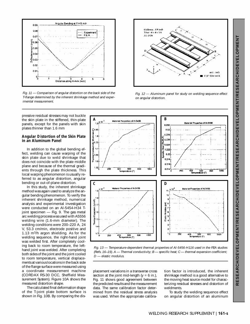
placement variations in a transverse crosssection at the joint mid-length (y = 6 in.),Fig. 11 shows good agreement betweenthe predicted results and the measurementdata. The same calibration factor deter-mined from the residual stress analysiswas used. When the appropriate calibra-
tion factor is introduced, the inherentshrinkage method is a good alternative tothe moving heat source model for charac-terizing residual stresses and distortion ofweldments.
To study the welding sequence effecton angular distortion of an aluminum
Fig. 11 — Comparison of angular distortion on the back side of theT-flange determined by the inherent shrinkage method and exper-imental measurement.
Fig. 12 — Aluminum panel for study on welding sequence effecton angular distortion.
Fig. 13 — Temperature-dependent thermal properties of Al-5456-H116 used in the FEA studies(Refs. 16–19). A — Thermal conductivity; B — specific heat; C — thermal expansion coefficient;D — elastic modulus.
A B
C D
panel, Fig. 12 shows the geometricconfiguration of the panel structureunder investigation. Both experimen-tal and numerical analyses have beenconducted. This paper presents onlythe details of numerical investigations.Some comparisons with the experi-mental results are also presented inthis paper. Details of both numericaland experimental studies can be foundin Ref. 15.
The numerical model assumed thatthe Ts were tack welded to the skinplate before structural welding. This in-dicates that the initial structural rigidityof the T-stiffeners was built into thepanel and provided an initial conditionfor the finite element analysis. Thewelding sequence simulation included1) laying the tack welds along the jointsand 2) laying structural welds at vari-ous joints with different sequences.The initial temperature condition foreach welding pass was room tempera-ture. The analysis was to investigate theeffect of welding sequence on angulardistortion of the skin plate.
In the finite element analysis, thegas metal arc welding process with 18
weld passes was simulated. The MPCcommend in the ABAQUS finite elementanalysis code was used to employ thetack welds. Temperature-dependent ma-terial properties of Al-5456, given inRefs. 16–19 and shown in Fig. 13, wereused in the finite element analysis.Weight of the panel was also incorpo-rated in the analysis. The panel is point-supported by ball joints at three cornerlocations (B, C and D in Fig. 12).
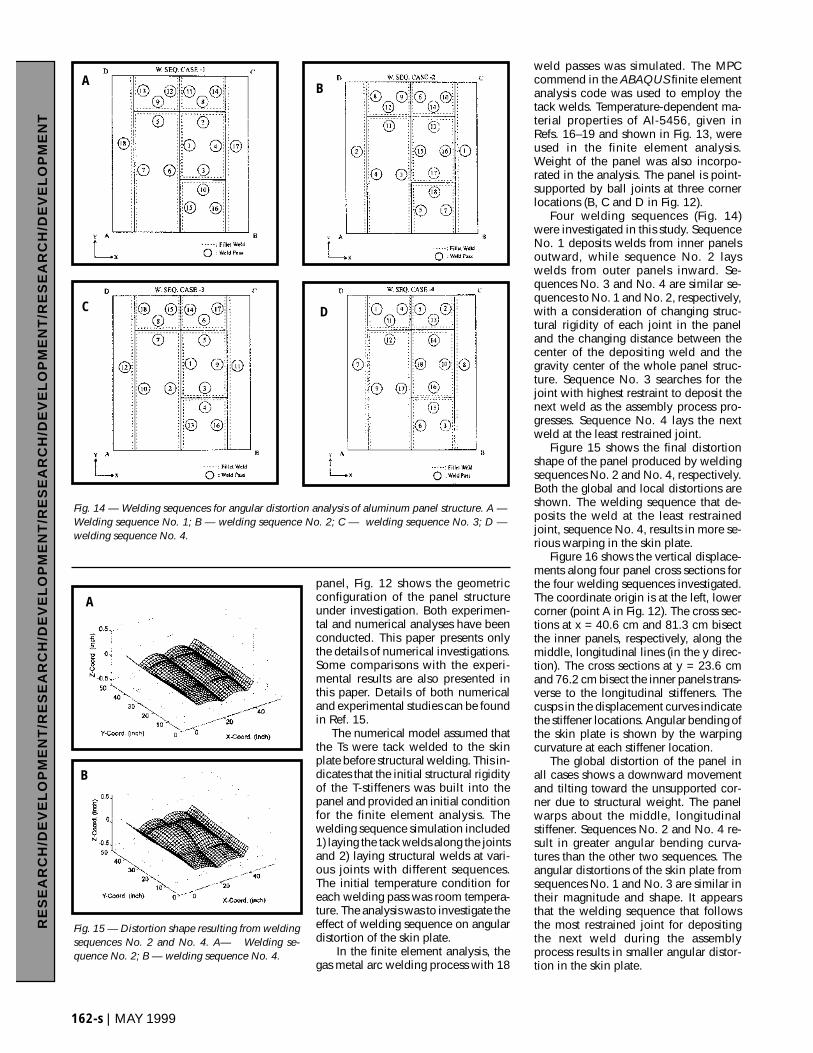
Four welding sequences (Fig. 14)were investigated in this study. SequenceNo. 1 deposits welds from inner panelsoutward, while sequence No. 2 layswelds from outer panels inward. Se-quences No. 3 and No. 4 are similar se-quences to No. 1 and No. 2, respectively,with a consideration of changing struc-tural rigidity of each joint in the paneland the changing distance between thecenter of the depositing weld and thegravity center of the whole panel struc-ture. Sequence No. 3 searches for thejoint with highest restraint to deposit thenext weld as the assembly process pro-gresses. Sequence No. 4 lays the nextweld at the least restrained joint.
Figure 15 shows the final distortionshape of the panel produced by weldingsequences No. 2 and No. 4, respectively.Both the global and local distortions areshown. The welding sequence that de-posits the weld at the least restrainedjoint, sequence No. 4, results in more se-rious warping in the skin plate.
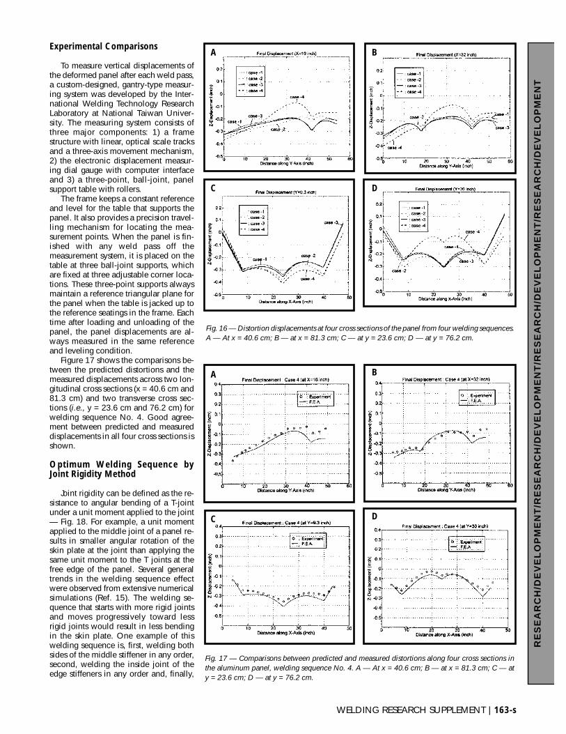
Figure 16 shows the vertical displace-ments along four panel cross sections forthe four welding sequences investigated.The coordinate origin is at the left, lowercorner (point A in Fig. 12). The cross sec-tions at x = 40.6 cm and 81.3 cm bisectthe inner panels, respectively, along themiddle, longitudinal lines (in the y direc-tion). The cross sections at y = 23.6 cmand 76.2 cm bisect the inner panels trans-verse to the longitudinal stiffeners. Thecusps in the displacement curves indicatethe stiffener locations. Angular bending ofthe skin plate is shown by the warpingcurvature at each stiffener location.
The global distortion of the panel inall cases shows a downward movementand tilting toward the unsupported cor-ner due to structural weight. The panelwarps about the middle, longitudinalstiffener. Sequences No. 2 and No. 4 re-sult in greater angular bending curva-tures than the other two sequences. Theangular distortions of the skin plate fromsequences No. 1 and No. 3 are similar intheir magnitude and shape. It appearsthat the welding sequence that followsthe most restrained joint for depositingthe next weld during the assemblyprocess results in smaller angular distor-tion in the skin plate.
162-s | MAY 1999
RE
SE
AR
CH
/DE
VE
LO
PM
EN
T/R
ES
EA
RC
H/D
EV
EL
OP
ME
NT
/RE
SE
AR
CH
/DE
VE
LO
PM
EN
T/R
ES
EA
RC
H/D
EV
EL
OP
ME
NT
A
A
B
B
C D
Fig. 14 — Welding sequences for angular distortion analysis of aluminum panel structure. A —Welding sequence No. 1; B — welding sequence No. 2; C — welding sequence No. 3; D —welding sequence No. 4.
Fig. 15 — Distortion shape resulting from weldingsequences No. 2 and No. 4. A— Welding se-quence No. 2; B — welding sequence No. 4.
Experimental Comparisons
To measure vertical displacements ofthe deformed panel after each weld pass,a custom-designed, gantry-type measur-ing system was developed by the Inter-national Welding Technology ResearchLaboratory at National Taiwan Univer-sity. The measuring system consists ofthree major components: 1) a framestructure with linear, optical scale tracksand a three-axis movement mechanism,2) the electronic displacement measur-ing dial gauge with computer interfaceand 3) a three-point, ball-joint, panelsupport table with rollers.
The frame keeps a constant referenceand level for the table that supports thepanel. It also provides a precision travel-ling mechanism for locating the mea-surement points. When the panel is fin-ished with any weld pass off themeasurement system, it is placed on thetable at three ball-joint supports, whichare fixed at three adjustable corner loca-tions. These three-point supports alwaysmaintain a reference triangular plane forthe panel when the table is jacked up tothe reference seatings in the frame. Eachtime after loading and unloading of thepanel, the panel displacements are al-ways measured in the same referenceand leveling condition.
Figure 17 shows the comparisons be-tween the predicted distortions and themeasured displacements across two lon-gitudinal cross sections (x = 40.6 cm and81.3 cm) and two transverse cross sec-tions (i.e., y = 23.6 cm and 76.2 cm) forwelding sequence No. 4. Good agree-ment between predicted and measureddisplacements in all four cross sections isshown.
Optimum Welding Sequence byJoint Rigidity Method
Joint rigidity can be defined as the re-sistance to angular bending of a T-jointunder a unit moment applied to the joint— Fig. 18. For example, a unit momentapplied to the middle joint of a panel re-sults in smaller angular rotation of theskin plate at the joint than applying thesame unit moment to the T joints at thefree edge of the panel. Several generaltrends in the welding sequence effectwere observed from extensive numericalsimulations (Ref. 15). The welding se-quence that starts with more rigid jointsand moves progressively toward lessrigid joints would result in less bendingin the skin plate. One example of thiswelding sequence is, first, welding bothsides of the middle stiffener in any order,second, welding the inside joint of theedge stiffeners in any order and, finally,
WELDING RESEARCH SUPPLEMENT | 163-s
RE
SE
AR
CH
/DE
VE
LO
PM
EN
T/R
ES
EA
RC
H/D
EV
EL
OP
ME
NT
/RE
SE
AR
CH
/DE
VE
LO
PM
EN
T/R
ES
EA
RC
H/D
EV
EL
OP
ME
NT
Fig. 16 — Distortion displacements at four cross sections of the panel from four welding sequences.A — At x = 40.6 cm; B — at x = 81.3 cm; C — at y = 23.6 cm; D — at y = 76.2 cm.
A
A
B
B
C
C
D
D
Fig. 17 — Comparisons between predicted and measured distortions along four cross sections inthe aluminum panel, welding sequence No. 4. A — At x = 40.6 cm; B — at x = 81.3 cm; C — aty = 23.6 cm; D — at y = 76.2 cm.
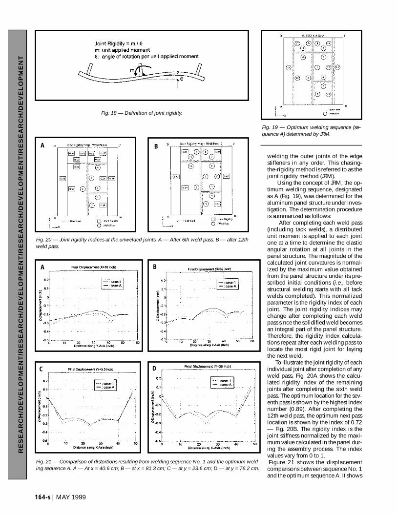
welding the outer joints of the edgestiffeners in any order. This chasing-the-rigidity method is referred to as thejoint rigidity method (JRM).
Using the concept of JRM, the op-timum welding sequence, designatedas A (Fig. 19), was determined for thealuminum panel structure under inves-tigation. The determination procedureis summarized as follows:
After completing each weld pass(including tack welds), a distributedunit moment is applied to each jointone at a time to determine the elasticangular rotation at all joints in thepanel structure. The magnitude of thecalculated joint curvatures is normal-ized by the maximum value obtainedfrom the panel structure under its pre-scribed initial conditions (i.e., beforestructural welding starts with all tackwelds completed). This normalizedparameter is the rigidity index of eachjoint. The joint rigidity indices maychange after completing each weldpass since the solidified weld becomesan integral part of the panel structure.Therefore, the rigidity index calcula-tions repeat after each welding pass tolocate the most rigid joint for layingthe next weld.
To illustrate the joint rigidity of eachindividual joint after completion of anyweld pass, Fig. 20A shows the calcu-lated rigidity index of the remainingjoints after completing the sixth weldpass. The optimum location for the sev-enth pass is shown by the highest indexnumber (0.89). After completing the12th weld pass, the optimum next passlocation is shown by the index of 0.72— Fig. 20B. The rigidity index is thejoint stiffness normalized by the maxi-mum value calculated in the panel dur-ing the assembly process. The indexvalues vary from 0 to 1.Figure 21 shows the displacementcomparisons between sequence No. 1and the optimum sequence A. It shows
164-s | MAY 1999
RE
SE
AR
CH
/DE
VE
LO
PM
EN
T/R
ES
EA
RC
H/D
EV
EL
OP
ME
NT
/RE
SE
AR
CH
/DE
VE
LO
PM
EN
T/R
ES
EA
RC
H/D
EV
EL
OP
ME
NT
A
C D
B
BA
Fig. 18 — Definition of joint rigidity.
Fig. 19 — Optimum welding sequence (se-quence A) determined by JRM.
Fig. 20 — Joint rigidity indices at the unwelded joints. A — After 6th weld pass; B — after 12thweld pass.
Fig. 21 — Comparison of distortions resulting from welding sequence No. 1 and the optimum weld-ing sequence A. A — At x = 40.6 cm; B — at x = 81.3 cm; C — at y = 23.6 cm; D — at y = 76.2 cm.
WELDING RESEARCH SUPPLEMENT | 165-s
RE
SE
AR
CH
/DE
VE
LO
PM
EN
T/R
ES
EA
RC
H/D
EV
EL
OP
ME
NT
/RE
SE
AR
CH
/DE
VE
LO
PM
EN
T/R
ES
EA
RC
H/D
EV
EL
OP
ME
NT
a significant reduction in angular distor-tion in the skin plate when the optimumwelding sequence is used.
Concluding Remarks
This study demonstrated that duringthe welding assembly of a panel structurea skin plate of normal thickness (e.g.,>1.6 mm) can only buckle when thepanel bends globally to cause a large cur-vature in the skin plate. The structuralweight and bending of the stiffeners re-sult in the global panel bending. Weldshrinkage in the T joints causes angulardistortion in the skin plate.
Locating welds closer to the neutralaxes of the panel cross sections can con-trol the global bending and minimizewelding distortion of a stiffened panel.Other mitigation methods include usingheavier stiffeners to increase the momentof inertia of the cross section or the egg-crate fabrication method to drasticallyimprove the bending resistance of thepanel structure.
Using the optimum welding sequencecan improve the flatness of the panel andminimize angular distortion in the skinplate. The joint rigidity method is effec-tive in determining the optimum weldingsequence for minimum angular distor-tion in the skin plate of stiffened panelstructures.
Acknowledgments
The authors would like to acknowl-edge China Shipbuilding Corp., HyundaiHeavy Industries, Ltd., and InternationalWelding Technology Research Labora-tory for supporting this study.
References
1. Terai, K., and Kurioka, T. 1969. FutureShipbuilding Methods. Kawasaki Heavy In-dustries, Ltd.
2. Watanabe, M., and Satoh, K. 1959. Fun-damental study on buckling of thin steel platedue to bead-welding. J. Japan Weld. Soc.27(6): 13–20.
3. Masubuchi, K. 1959. New approach tothe problem on residual stress and deforma-tion due to welding. Transportation TechnicalResearch Institute Report 8(12).
4. Taniguchi, C. 1972. Out-of-plane dis-tortion caused by fillet welds in aluminum.Master’s thesis. MIT, Cambridge, Mass.
5. Pattee, F. M. 1975. Buckling distortionof thin aluminum plates during welding. Mas-ter’s thesis. MIT, Cambridge, Mass.
6. Satoh, K., and Terasaki, T. 1976. Effectof welding conditions on residual stress distri-butions and welding deformation in weldedstructures materials. J. Japan Weld. Soc. 45(1):42–53.
7. Terai, K., Matsui, S., Kinoshita, T., et al.1976. Study on Prevention of Welding Defor-mation in Thin-Skin Plate Structures.Kawasaki Technical Review 61: 61–66.
8. Penso, J. A. 1992. Development of a PC-based FEM model to predict weld distortion.Master’s thesis. The Ohio State University,Columbus, Ohio.
9. Daniewicz, S. R., McAninch, M. D., Mc-Farland, B., and Knoll, D. 1993. Applicationof distortion control technology during fabri-cation of large offshore structures. Proc. ofAWS/ORNL International Conference onModeling and Control of Joining Processes.
10. Michaleris, P., and DeBiccari, A. 1997.Prediction of welding distortion. WeldingJournal 76(4): 172-s to 179-s.
11. Burak, et al. 1977 and 1979. Automatic
Welding, 3 and 5.12. Guan, Q., Leggatt, R. H., and Brown,
K. W. 1988. Low stress, non-distortion (LSND)TIG welding of thin-walled structural ele-ments. The Welding Institute Research Report374. Abington, Cambridge, U.K.
13. Guan, Q., Guo, D., et al. 1987.Method and Apparatus for Low Stress andNon-Distortion Welding of Thin-WalledStructural Elements. Chinese Patent No.87100959.
14. Guan, Q., Brown, K. W., Guo, D., etal. 1988. International patent specificationNo. PCT/GB88/00136.
15. Park, S. C. 1988. Distortion mecha-nisms and control methodology for weldingthin-plate panel structures. Ph.D dissertation,The Ohio State University, Columbus, Ohio.
16. Thermophysical Properties ResearchCenter. 1973. Properties of aluminum and alu-minum alloys. TPRC Report 21. Purdue Uni-versity.
17. Metals Handbook, Vol. 2, 10th edition.1990. ASM International, Materials Park,Ohio.
18. CINDAS, Structural Alloys Handbook.1994. Purdue University.
19. Voorhees, H. R., and Freeman, J. W.1960. Report on the elevated temperatureproperties of aluminum and magnesium al-loys, ASTM STP no. 291.