Embed Size (px)
Citation preview

1
Sensing products to boost welding productivityWeld Select Series

www.balluff.com/welding2
Weld Select Series Weld Select is an industry proven group of Balluff products designed for use in the most inhospitable welding environments. Poor sensor selection costs welders in every industry increased downtime, unnecessary maintenance, delayed delivery, and lost profits. Now Balluff presents a complete package of welding solutions that extends sensor life and increases productivity in the harshest welding environments.
This guide contains two sections. The front section is designed to help all plant levels identify existing issues and offer Balluff-developed solutions to address them. The second section, beginning on page 10, offers an extensive list of products developed by Balluff welding experts from valuable customer input. These products have been tested in the harshest welding environments and provide significant process and part quality improvement.
www.balluff.com/welding
n Welding Application Reportsn Industry Articlesn Sensor Informationn Case Studies
n Stop Wasting Sensors and destroying connectors
n Change the Paradigm of accepted high volume sensor usage
n Reduce Downtime due to sensor failure
n Slash Consumption of sensors and connectors
n Boost Profitability throughout the plant
Examples of common weld cell problems that we've solved:
Weld Repel® Wrap and TPE cables provide flexibility and resistance to weld slag, lubricants, and connector burn-through.
Unprotected and non-bunkered sensors, sensors in damage-prone areas, and/or lighweight brackets.
Bunker Blocks™ and SlagMaster® coating allow full protection against harsh impact.
Damage to unprotected sensor faces and cables caused by impact and contact.
Slag accumulation and unprotected pigtail sensors cause large amounts of downtime.
PTFE coated Prox-Mounts and Weld Repel® tubing over sacrificial cables improve sensor life and productivity.

3
Welding EnvironmentNon-contact inductive proximity sensors must perform a wide variety of clamping and nesting indication, and Poka-Yoke functions in harsh welding environments. Hot weld slag accumulation, elevated ambient temperatures, and strong electromagnetic fields emitted by weld guns can cause false triggering and degrade sensor performance.
PROBLEMStrong electromagnetic fields cause conventional sensors to false trigger or “chatter.”
SOLUTIONBalluff inductive proximity and magnetic field sensors with weld field immunity (WFI) resist electromagnetic fields emitted by weld guns up to 100 kA/m.
Electromagnetic Weld Fields
Weld Slag
PROBLEMHot welding slag (a.k.a. weld debris, weld spatter, weld berries) sticks to sensor faces and bodies and causes premature failure of sensors in weld cells.
SOLUTION
Balluff SlagMaster® coating on sensor faces resists weld debris and provides a thermal barrier, significantly enhancing sensor longevity, and reducing false triggering. PTFE coated sensor bodies resist weld debris accumulation and promote slag removal during regular scheduled maintenance periods.
®
WELDING CONCERNS

www.balluff.com/welding4
PROBLEMSevere loading impact and continuous operational impact damages plastic and/or PTFE sensor faces as well as sensor bodies.
SOLUTION
Every precaution should be taken to prevent electronics such as sensors from being hit, but in many cases, loading impact cannot be avoided. By nesting a Balluff SteelFace® inductive proximity sensor into a rugged Prox Mount or Bunker Block™, the likelihood of premature failure becomes lessened, even with repeated impact over time.
Loading ImpactIncidental sensor damage caused by parts loading impact can significantly degrade sensor performance, shorten sensor life, or even destroy a sensor. Balluff SteelFace® inductive proximity sensors can withstand multiple heavy impacts and abrasion, and often have the sensing range to be placed out of harm’s way.
Damage from Loading Impact
Sensor Face Damaged by Impact
PROBLEMStandard tubular sensors often fail from damage to the sensor face and coil caused by slag and impact. Over time, small repeated impacts can damage the face and lead to sensor failure.
SOLUTION
Balluff SteelFace® inductive proximity sensors with extended range and stainless steel housings resist impact, providing long life in weld cell impact zones. Balluff Bunker Blocks™ and Prox Mounts provide sensors an extraordinary degree of physical protection, preventing contact damage to the sensor body and face as well as rapid sensor removal and replacement without need for recalibration.
®
LOADING IMPACT

5
Cylinder & Clamp PositionParts welded in a robotic weld cell must be nested and held in place by pneumatically or hydraulically actuated clamps which are often equipped with sensors located in the clamp jaws to indicate “clamped” or “unclamped” position. Clamp position can also be determined by magnetic field sensors located on the outer wall of an aluminum or composite pneumatic cylinder. To determine clamping position, a Balluff BMF magnetoresistive sensor tracks the magnetic field emitted by a magnet attached to the cylinder’s piston. In high-pressure hydraulic cylinders, Balluff StrokeMaster® end-of-stroke sensors detect the “spud” or cushion of a piston shaft to sense clamp position.
PROBLEMHigh-pressure hydraulic welding clamps need the right sensors to accurately sense piston extend/retract position and may require electronic weld field immune sensors.
SOLUTION
Balluff StrokeMaster® high pressure-rated end-of-stroke sensors accommodate pressures up to 3,000 PSI and fit virtually all common cylinder brands and bore sizes. StrokeMaster heads swivel to direct connector wiring away from weld hostility.
Cylinders & Clamps Need Stroke Detection
Premature Reed Switch Failure
PROBLEMWhen installed on pneumatic clamping cylinders, failure-prone reed switches and drift-prone Hall Effect sensors deteriorate, often providing inaccurate switch points before failing completely.
SOLUTION
Balluff BMF magnetoresistive sensors come with a lifetime warranty and fit virtually all cylinder housing styles and brands. They provide precise switch points and withstand the rigors of the weld process, while providing wear free, non-contact reliability.
CYLINDER & CLAMPLOADING IMPACT

www.balluff.com/welding6
PROBLEMFiber optics can become occluded in the weld cell and stop functioning. They can become broken when weld fixtures are removed, causing fibers to vibrate loose. Cables with excess length break when tied back and get damaged by slag.
SOLUTION
Typically, fiber optic solutions are not the best choice in weld cells. Metal-body laser sensors or inductive proximity sensors are almost always a better choice.
Photoelectric SensorsPhotoelectric and fiber optic sensors require special protection and mounting expertise when integrated into welding cells. Balluff has a wide range of photoelectrics with application-specific infrared, red, or laser capability that can reliably sense through smoke, oil and dirt. In addition, Balluff provides a range of accessories that protect photoelectric optics from heat, slag, and lens occlusion in the hostile weld cell environment.
Fiber Optic Limitations
Damage by Loading Impact
PROBLEMImpact-prone photoelectric sensors can easily become physically damaged in welding environments.
SOLUTION
Bunker Blocks™ and Prox Mounts can be used to protect tubular photoelectric sensors. They provide a thermal barrier, protect against weld slag and impact, and provide rapid sensor change out. Bunker Blocks™, available in several sizes and styles, protect block style photoelectric sensors in the weld environment.
PHOTOELECTRICS

7
Protecting ConnectivityWeld cells demand the toughest connectivity solutions. Hot debris, cable flex, UV radiation, and high ambient heat can damage peripheral devices. PVC jacketed sensor connectors, fine for clean and dry applications, are generally unsuitable for welding environments. Today, PUR (polyurethane) connector jacketing is being replaced with superior high-flex, chemical-resistant TPE (thermoplastic elastomer) jacket materials that can better withstand well cell punishment. Now, TPE connectivity components teamed with Balluff Weld Repel® products can result in reduced weld cell material costs and downtime plus increased system longevity and overall profitability.
PROBLEMWeld slag burns through and destroys conventional cabling. It’s weight often pulls the cable away from the connector, exposing it to even more damage.
SOLUTION
Balluff TPE cables provide exceptional burn-through resistance. Especially in conjunction with Balluff Weld Repel® tubing, typical problems with insulation burn through disappear. When self-bonding Weld Repel wrap is used to attach Weld Repel tubing to the sensor connector, all gaps allowing debris are eliminated while remaining transparent for viewing LEDs. Use Weld Repel area protection sheets to protect large areas from debris.
Sensor Cable Burn-Through
Network I/O Blocks Damaged
PROBLEMSensor connections often terminate into plastic junction blocks or network blocks which can easily be damaged in welding cells.
SOLUTION
A rugged line of industrial I/O products designed for use in the harshest environments offer a greater degree of strength and durability for applications like robotic welding cells. Most major bus and Ethernet based industrial networks are supported and provide detailed diagnostics on the connections from short circuit protection to network status. In the dark confines of a weld cell, the bright and large LEDs are easy to see.
PHOTOELECTRICS CONNECTIVITY

www.balluff.com/welding8
PROBLEMRotational weld cells, or cells that use interchangeable fixtures, often incur high maintenance and frequent stoppages due to damaged slip rings, tangled, over-flexed, or twisted wiring.
SOLUTION
Non-contact connector systems provide communication between two or more separated weld cell components through an air gap to energize and communicate between the controller and the sensors. Because there is no hard wired connection, weld fixtures can be inserted into a weld cell frame without the need for mechanical connections, facilitating rapid change out, and improved operator safety.
Non-Contact ConnectorsInterchangeable weld fixtures and rotating weld tables often require the use of troublesome, expensive, and high-maintenance contact-based rotating assemblies such as slip rings or commutator ring/brush solutions. In many cases wires inevitably fray and break. In contrast, Balluff’s unique non-contact connectors provide a wear free connectivity, powering sensors and providing control information across an air gap.
Broken or Worn Out Communicator Rings
How Non-Contact Connectors Work
NON-CONTACT
Think of this like a mechanical connector without pins or the requirement of physical contact. When connected, power goes out to the devices and signals come back from the devices. Depending on the specific product of interest, different information can be passed. Power only or power plus, discrete inputs and outputs, or analog voltage signals can be transmitted across the air gap. Each base head is mounted on the controller side of the application and as many remote heads as needed are mounted on the sensors/actuators side of the application.
Inductive Coupling
Multiple Sensors PLC<15mm
Remote Base
Signal
Power
Signal
Power
Signal
Power
9
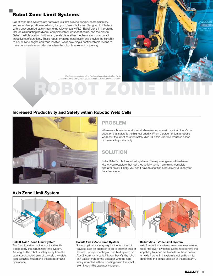
Robot Zone Limit SystemsBalluff zone limit systems are hardware kits that provide diverse, complementary, and redundant position monitoring for up to three robot axes. Designed to interface with a user-supplied safety monitoring relay or safety PLC, Balluff zone limit systems include all mounting hardware, complementary redundant cams, and the proven Balluff multiple position limit switch, available in either mechanical or non-contact inductive configurations. These robust systems install easily and provide the flexibility to adjust zone angles and zone location, while providing a control-reliable means to mute personnel sensing devices when the robot is safely out of the way.
PROBLEMWherever a human operator must share workspace with a robot, there’s no question that safety is the highest priority. When a person enters a robotic work cell, the robot must be safely idled. But this idle time results in a loss of the robot’s productivity.
SOLUTION
Enter Balluff’s robot zone limit systems. These pre-engineered hardware kits let you recapture that lost productivity, while maintaining complete operator safety. Finally, you don’t have to sacrifice productivity to keep your floor team safe.
Increased Productivity and Safety within Robotic Weld Cells
Axis Zone Limit System
ROBOT ZONE LIMIT
Balluff Axis 1 Zone Limit SystemThe Axis 1 position of the robot is directly detected by the Balluff zone limit system. As long as the robot is safely away from the operator-occupied area of the cell, the safety light curtain is muted and the robot remains operational.
Balluff Axis 2 Zone Limit SystemSome applications may require the robot arm to traverse past an operator to go to another area of the cell. By implementing a zone limit system on Axis 2 (commonly called “boom back”), the robot can pass in front of the operator with the arm safely retracted without shutting down the robot, even though the operator is present.
Balluff Axis 3 Zone Limit SystemAxis 3 zone limit systems are sometimes referred to as “flip over” switches. Some robots have the capability to reach backwards. In these cases, an Axis 1 zone limit system is not sufficient to determine the actual position of the robot arm.
Pre-Engineered Automation System: Fanuc ArcMate Robot with Lincoln Electric Welding Package, featuring the Balluff zone limit system.

www.balluff.com/welding10
SlagMaster® coating significantly prolongs sensor life by providing a thermal barrier to protect against heat, retarding build up of weld spatter and slag, and easing removal of surrounding deposits of weld debris during scheduled maintenance periods.
The parts listed below are non-weld field immune sensors and without PTFE-coating. For PTFE-coated, weld field immune sensors, see page 14.
Inductive SensorsSlagMaster® coating
Order Code Sensing Distance
Output Logic
Housing Material Wiring Diag.
Drawing Dimensions Connection
A B C
3-Wire DC, Non-Weld Field Immune, SlagMaster
M8 Tubular, Flush, 10…30VDC, Non-Weld Field Immune
BES02P5 2 mm PNP, N/O Stn. Stl. A 5 30 30 M8 M12, 0.3m PUR Pigtail
BES02P0 2 mm PNP, N/O Stn. Stl. A 1 45 34.5 M8 M8
BES02P1 2 mm NPN, N/O Stn. Stl. B 1 45 34.5 M8 M8
BES02PN 2 mm NPN, N/O Ni CuZn B 1 65 45 M8 M12
BES02PU 2 mm PNP, N/O Ni CuZn A 1 65 45 M8 M12
BES0149 2 mm PNP, N/O Stn. Stl. A 1 43 28.5 M8 M12
BES0388 2 mm PNP, N/O St. Bk Zn Chromate A 5 20.5 20.5 M8 M12, 1.0m PUR Pigtail
M8 Tubular, Quasi Flush, 10…30VDC, Non-Weld Field Immune
BES02PW 3 mm PNP, N/O Ch CuZn A 1 66 40 M8 M12
M12 Tubular, Flush, 10…30VDC, Non-Weld Field Immune
BES0450 4 mm PNP, N/O CuZn A 1 45 30 M12 M12
BES035R 4 mm PNP, N/O Ni CuZn A 1 70 40 M12 M12
BES03UP 4 mm NPN, N/O CuZn B 1 45 30 M12 M12
M18 Tublar, Flush, 10…30VDC, Non-Weld Field Immune
BES02P3 8 mm PNP, N/O Ni CuZn A 1 44.5 29.5 M18 M12
BES02P4 8 mm NPN, N/O Ni CuZn B 1 44.5 29.5 M18 M12
20mm x 32mm Block, Flush, 10…30VDC, Non-Weld Field Immune
BES02PM 7 mm PNP, N/O GD-Zn A 2 32 20 8 M12, 0.2m TPU Pigtail
BES02PR 7 mm PNP, N/O GD-Zn A 2 32 20 8 M8, 0.2m PUR Pigtail
BES03ZL 7 mm PNP, N/O GD-Zn A 2 32 20 8 M8, 1.5m PUR Pigtail, Irradiated
BES02PL 7 mm PNP, N/O GD-Zn A 2 32 20 8 5m, PUR, Irradiated
BES02PT 7 mm PNP, N/O GD-Zn A 2 32 20 8 M12, 0.2m PUR Pigtail
BES0314 7 mm PNP, Comp GD-Zn D 2 32 20 8 M12, 0.2m PUR Pigtail w/WeldRepel Tubing
BES02KY 7 mm PNP, N/O GD-Zn A 2 32 20 8 M8, 0.2m PUR Pigtail w/WeldRepel Tubing
40mm x 40mm Cube, Flush, 10…30VDC, Non-Weld Field Immune
BES0455 20 mm PNP, Comp PBT D 3 62 40 40 M12
40mm x 40mm Cube, Non-Flush, 10…30VDC, Non-Weld Field Immune
BES0456 30 mm PNP, Comp PBT D 5 62 40 40 M12
B
C
D
APNP, N/O
NPN, N/O PNP, Comp
Polarized N/O Non-Polarized, N/O
E
F
AC/DC, N/O

11
5
Order Code Sensing Distance
Output Logic Housing Material Wiring Diagram
Drawing Dimensions Connection
A B C
2-Wire DC, Non-Weld Field Immune, SlagMaster
M8 Tubular, Flush, 2-Wire DC, 10…30VDC, Polarized, Non-Weld Field Immune
BES00C0 2 mm N/O CuZn C 1 50 29.5 M8 M12
BES0324 2 mm N/O CuZn C 5 40 40 M8 M12, 0.3m PUR Pigtail
M12 Tubular, Flush, 2-Wire DC, 10…30VDC, Polarized, Non-Weld Field Immune
BES00C1 3 mm N/O CuZn C 1 50 35.5 M12 M12
BES0326 3 mm N/O CuZn C 5 43 40.5 M12 M12, 0.3m PUR Pigtail
M18 Tubular, Flush, 2-Wire DC, 10…30VDC, Polarized, Non-Weld Field Immune
BES0329 7 mm N/O CuZn C 5 46 40 M18 M12, 0.3m PUR Pigtail
M30 Tubular, Flush, 2-Wire DC, 10…30VDC, Polarized, Non-Weld Field Immune
BES032A 15 mm N/O CuZn C 5 42.5 40 M30 M12, 0.3m PUR Pigtail
20mm x 32mm Block, Flush, 10…30VDC, Non-Polarized, Non-Weld Field Immune
BES03TM 5 mm N/O GD-ZN E 2 32 20 8 M12, 0.2m PUR Pigtail
2-Wire AC/DC, Non-Weld Field Immune, SlagMaster
M12 Tubular, Non-Flush, 3-Wire AC/DC, 20…250V AC/DC, Non-Weld Field Immune
BES044A 4 mm N/O Stn. Stl. F 1 70 40.5 M12 1/2-20 UNF - 2A
High Temperature 120° C, Non-Weld Field Immune, SlagMaster
M8 Tubular, Flush, High Temperature 120º C, 10…30VDC, Non-Weld Field Immune
BES02HY 2 mm PNP, N/O Stn. Stl. A 1 55.5 55.5 M8 PTFE, 3m Cable
M12 Tubular, Flush, High Temperature 120º C, 10…30VDC, Non-Weld Field Immune
BES02HZ 2 mm PNP, N/O Ni CuZn A 1 75 40.5 M12 Silicon, 3m cable
M18 Tubular, Flush, High Temperature 120º C, 10…30VDC, Non-Weld Field Immune
BES032K 5 mm PNP, Comp Ni CuZn D 1 83 60 M18 M12
M30 Tubular, Flush, High Temperature 120º C, 10…30VDC, Non-Weld Field Immune
BES02J3 5 mm PNP, N/O GOAISi12 A 4 50 25 10 Silicon, 3m cable
C
B A
C
A
B
A
8
C B
15
4.2
Sensing face
1 2 3 4
A46
B
40
30
C
A
Drawings for reference only. Visit www.balluff.com for the most up-to-date specifications and data sheets.

www.balluff.com/welding12
Inductive SensorsSlag resistant housingPTFE-coating helps prevent hot weld slag from sticking to the metal sensor body. In areas where weld slag is inevitable, the slick PTFE-coating makes it easier to quickly remove the weld slag without damaging the sensor.
The parts listed below are non-weld field immune.
Order Code Sensing Distance
Output Logic
Housing Material Wiring Diagram
Drawing Dimensions Connection
A B C
2-Wire DC, Non-Weld Field Immune, PTFE Coated
M8 Tubular, Flush, 2-Wire DC, 10…36VDC, Polarized, Non-Weld Field Immune
BES039R 2 mm N/O CuZn C 1 50 29.5 M8 M12
BES039T 2 mm N/O CuZn C 3 40 40 M8 M12, .3m PUR Pigtail, Irradiated
M8 Tubular, Flush, 2-Wire DC, 10…36VDC, Non-Polarized, Non-Weld Field Immune
BES03H7 2 mm N/O CuZn E 1 50 29.5 M8 M12
M12 Tubular, Flush, 2-Wire DC, 10…36VDC, Polarized, Non-Weld Field Immune
BES039U 3 mm N/O CuZn C 1 50 35.5 M12 M12
BES039W 3 mm N/O CuZn C 3 43 40 M12 M12, .3m PUR Pigtail, Irradiated
M12 Tubular, Flush, 2-Wire DC, 10…36VDC, Non-Polarized, Non-Weld Field Immune
BES03HL 3 mm N/O CuZn E 1 50 35.5 M12 M12
M18 Tubular, Flush, 2-Wire DC, 10…36VDC, Polarized, Non-Weld Field Immune
BES03FH 7 mm N/O CuZn C 1 51 35 M18 M12
BES03FJ 7 mm N/O CuZn C 3 46 40 M18 M12, .3m PUR Pigtail, Irradiated
M18 Tubular, Flush, 2-Wire DC, 10…36VDC, Non-Polarized, Non-Weld Field Immune
BES0398 7 mm N/O CuZn E 1 51 35 M18 M12
M30 Tubular, Flush, 2-Wire DC, 10…36VDC, Polarized, Non-Weld Field Immune
BES027K 15 mm N/O CuZn C 3 42.5 40 M30 M12, .3m PUR Pigtail, Irradiated
BES03KL 15 mm N/O CuZn C 1 51 35 M30 M12
M30 Tubular, Flush, 2-Wire DC, 10…36VDC, Non-Polarized, Non-Weld Field Immune
BES03FR 15 mm N/O CuZn E 1 51 35 M30 M12
B
C
D
APNP, N/O
NPN, N/O PNP, Comp
Polarized N/O Non-Polarized, N/O
E
F
AC/DC, N/O
+/-
-/+

13
Inductive SensorsUltra high temperature-resistant sensorsFor applications that require reliable sensor function at high ambient temperature, Balluff offers high temperature-resistant sensors. Capable of operating in temperatures as high as 160° F, Balluff high temperature sensors meet either IP67 or IP69 ratings.
The following sensors are non-weld field immune.
Order Code Sensing Distance
Output Logic
Housing Material Wiring Diagram
Drawing Dimensions Connection
A B C D
High Temperature 120° C, Non-Weld Field Immune, SlagMaster
M8 Tubular, Flush, High Temperature 120º C, 10…30VDC, Non-Weld Field Immune
BES02HY 2 mm PNP, N/O Stn. Stl. A 1 55.5 55.5 M8 PTFE, 3m Cable
M12 Tubular, Flush, High Temperature 120º C, 10…30VDC, Non-Weld Field Immune
BES02HZ 2 mm PNP, N/O Ni CuZn A 1 75 40.5 M12 Silicon, 3m cable
M18 Tubular, Flush, High Temperature 120º C, 10…30VDC, Non-Weld Field Immune
BES032K 5 mm PNP, Comp Ni CuZn D 1 83 60 M18 M12
M30 Tubular, Flush, High Temperature 120º C, 10…30VDC, Non-Weld Field Immune
BES02J3 5 mm PNP, N/O GOAISi12 A 4 50 25 10 Silicon, 3m cable
High Temperature 160° C, IP69 Rated, Non-Weld Field Immune, Non-SlagMaster Coated
M18 Tubular, Flush, High Temperature 160º C, 10…30VDC, Non-Weld Field Immune
BES043T 5 mm PNP, N/O Stn. Stl. A 1 80 60 M18 FEP, 2m cable
M18 Tubular, Non-Flush, High Temperature 160º C, 10…30VDC, Non-Weld Field Immune
BES043U 8 mm PNP, N/O Stn. Stl. A 2 80 60 M18 8 FEP, 2m cable
M30 Tubular, Flush, High Temperature 160º C, 10…30VDC, Non-Weld Field Immune
BES043W 10 mm PNP, N/O Stn. Stl. A 1 85 65 M30 FEP, 2m cable
M30 Tubular, Non-Flush, High Temperature 160º C, 10…30VDC, Non-Weld Field Immune
BES043Y 15 mm PNP, N/O Stn. Stl. A 2 85 65 M30 10 FEP, 2m cable
C
B A
C
A
B
1 2 3
C
A
4
C
BD
A
Drawings for reference only. Visit www.balluff.com for the most up-to-date specifications and data sheets.

www.balluff.com/welding14
Weld field immune inductive sensors are used for work-piece positioning in welding areas where strong magnetic fields influence ordinary sensors oscillator/coil systems. This leads to false switching when no target is present. Balluff weld field immune inductive sensors can be mounted in the direct vicinity of welding tongs or electrodes, since welding currents of up to 100 kA do not affect the switching function of the sensor.
Inductive SensorsWeld Field Immune
Order Code Sensing Distance
Output Logic Housing Material
SlagMaster Coating
Wiring Diagram
Drawing Dimensions Connection
A B C D
M12 Flush Tubular, 10…30VDC, Weld Field Immune
BES02J4 2 mm PNP, Comp PTFE Stn. Stl. B 1 61 40 M12 M12
BES02J5 2 mm PNP, N/O PTFE CuZn A 1 61 40 M12 M12
BES02J6 2 mm PNP, N/O PTFE CuZn A 1 61 40 M12 M12
BES02J8 2 mm PNP, N/O PTFE CuZn n A 1 61 40 M12 M12
BES02K1 3 mm PNP, N/O PTFE CuZn A 1 65 50 M12 M12
BES02K2 3 mm PNP, N/O PTFE CuZn n A 1 65 50 M12 M12
M12 Non-Flush Tubular, 10…30VDC, Weld Field Immune
BES02JM 4 mm PNP, N/O PTFE Stn. Stl. A 2 61 35 M12 5 M12
BES02JN 4 mm PNP, N/O PTFE Stn. Stl. A 2 61 35 M12 5 M12
BES02JY 8 mm PNP, N/O PTFE CuZn n A 2 50 26 M12 10 M12
M18 Flush Tubular, 10…30VDC, Weld Field Immune
BES02J9 5 mm PNP, N/O PTFE CuZn A 1 65 40 M18 M12
BES02JA 5 mm PNP, N/O PTFE CuZn A 1 65 40 M18 M12
BES02JC 5 mm PNP, N/O PTFE CuZn n A 1 83 50 M18 M12
BES02JE 5 mm PNP, N/O PTFE CuZn A 1 80 59.5 M18 M12
BES02JF 5 mm PNP, N/O PTFE CuZn n A 1 65 40 M18 M12
BES02KC 7 mm PNP, N/O PTFE CuZn A 1 65 50 M18 M12
BES02KE 7 mm PNP, N/O PTFE CuZn n A 1 65 50 M18 M12
M18 Non-Flush Tubular, 10…30VDC, Weld Field Immune
BES02JP 8 mm PNP, N/O PTFE CuZn A 2 65 30 M18 10 M12
BES02JR 8 mm PNP, N/O PTFE CuZn A 2 65 30 M18 10 M12
BES02K8 12 mm PNP, N/O PTFE CuZn n A 2 50 25.5 M18 10 M12
M30 Flush Tubular, 10…30VDC, Weld Field Immune
BES02JH 10 mm PNP, N/O PTFE CuZn A 1 65 40 M30 M12
BES02JJ 10 mm PNP, N/O PTFE CuZn A 1 65 40 M30 M12
BES02JL 10 mm PNP, N/O PTFE CuZn n A 1 65 40 M30 M12
BES02KL 13 mm PNP, N/O PTFE CuZn A 1 65 50.5 M30 M12
BES03F1 13 mm PNP, N/O PTFE CuZn n A 1 65 50.5 M30 M12
M30 Non-Flush Tubular, 10…30VDC, Weld Field Immune
BES02JU 15 mm PNP, N/O PTFE CuZn A 2 65 27 M30 13 M12
BUNKERPROX
Order Code Sensing Distance
Output Logic
Housing Material
SlagMaster Coating
Wiring Diagram
Drawing Dimensions Connection
A B C D
M18 Flush Tubular, 10…30VDC, Weld Field Immune
BES03MY 4 mm PNP, N/O PTFE CuZn n A 1 65 50 M18 M12
Balluff’s BunkerProx is a rugged, “self-bunkering” M18 inductive proximity sensor specially designed to survive longer in abusive welding applications without external protection. The strong, massively thick housing has the ability to withstand repeated mechanical impacts and also serves as an intermittent heat sink to shield the sensor electronics from the intense heat of red-hot weld slag. A frontal impact deflection ring helps protect the high-temperature ceramic face from impact damage during part loading and unloading.

15
Order Code
Sensing Distance
Output Logic
Housing Material
SlagMaster Coating
Wiring Diag.
Drawing Dimensions Connection
A B C D
Block 20 x 32, Flush 10…30VDC, Weld Field Immune
BES02KR 5 mm PNP, N/O GD-Zn n A 3 32 20 8 M12 PUR .2m Pigtail
BES0313 5 mm PNP, N/O GD-Zn n A 3 32 20 8 M12 PUR .2m (Irradiated) Pigtail w/WeldRepel Tubing
BES02KT 5 mm PNP, N/O GD-Zn n A 3 32 20 8 M12 PUR .2m Pigtail
BES02KU 5 mm PNP, N/O GD-Zn n A 3 32 20 8 M12 PUR .2m Pigtail w/WeldRepel Tubing
BES01W7 5 mm PNP, N/O GD-Zn A 3 32 20 8 M8 PUR .2m Pigtail
BES01W8 5 mm PNP, N/O GD-Zn A 3 32 20 8 M12 PUR .5m Pigtail
BES01W9 5 mm PNP, N/O GD-Zn A 3 32 20 8 M8 PUR .5m Pigtail
BES01WC 5 mm PNP, N/O GD-Zn A 3 32 20 8 3m PUR (Irradiated) Cable
BES02KW 5 mm PNP, N/O GD-Zn n A 3 32 20 8 M12 5m PUR (Irradiated) Pigtail
Block 20 x 32, Flush 10…30VDC, Weld Field Immune
BES0230 15 mm PNP, N/O PBT A 4 120 40 40 M20 x 1.5 Conduit
BES0231 15 mm PNP, N/O PBT A 4 132.5 40 40 M12
M18 Flush Tubular, 20…250V AC/DC, Weld Field Immune
BES02KZ 5 mm N/O PTFE CuZn C 1 80 46 M18 1/2-20 UNF - 2A
BES02L0 5 mm N/O PTFE CuZn C 1 80 46 M18 1/2-20 UNF - 2A
BES02L3 5 mm N/O PTFE CuZn n C 1 80 46 M18 1/2-20 UNF - 2A
BES02L4 5 mm N/O PTFE CuZn n C 1 80 46 M18 1/2-20 UNF - 2A
M18 Flush Tubular, 20…250V AC/DC, Weld Field Immune
BES02L1 5 mm N/O PTFE CuZn C 5 67 35.5 M18 44 1/2-20 UNF - 2A
BES02L2 5 mm N/O PTFE CuZn C 5 67 35.5 M18 44 1/2-20 UNF - 2A
40mm x 40mm Cube, Flush, 10…30VDC, Weld Field Immune
BES022L 15 mm PNP, Comp PBT B 6 62 40 40 M12
BES0215 15 mm PNP, Comp PBT n B 6 62 40 40 M12
40mm x 40mm Cube, Non-Flush, 10…30VDC, Weld Field Immune
BES021C 25 mm PNP, Comp PBT B 6 62 40 40 M12
BES021J 35 mm PNP, Comp PBT B 6 62 40 40 M12
BES021L 35 mm PNP, Comp PBT n B 6 62 40 40 M12
BES021M 40 mm PNP, Comp PBT B 6 62 40 40 M12
2 3 4 51
C
BD
A
C B
A
A
6046 B
30
40
Ø5.
3
7.3
7.36.
5
C
A
C
B
D
BAPNP, N/O PNP, Comp
C
AC/DC, N/O
C
B A
Drawings for reference only. Visit www.balluff.com for the most up-to-date specifications and data sheets.
6
A46
B
40
30

www.balluff.com/welding16
Balluff Factor 1 sensors have special dual coil electronic circuitry whose function is unaffected by strong magnetic fields found in processes such as induction hardening and welding environments. They also come equipped with PTFE-coated housings resistant to weld splatter.
Factor 1 sensors detect all metals at the same distance. There is no need to de-rate the sensing distance based on target material. Factor 1+ sensors provide greater switching distances for increased performance.
Inductive Sensors Factor 1 - Weld Field Immune
Order Code Sensing Distance
Output Logic Housing Material
SlagMaster Coating
Wiring Diagram
Drawing Dimensions Connection
A B C D
Factor 1
M8 Flush Tubular, 10…30VDC, Weld Field Immune - Factor 1
BES02YT 1.5 mm PNP, N/O PTFE Stn. Stl. A 1 57 40 M8 M12
BES02YR 1.5 mm PNP, N/O PTFE Stn. Stl. A 1 49 40 M8 M8
M12 Flush Tubular, 10…30VDC, Weld Field Immune - Factor 1
BES02JZ 3 mm PNP, N/O PTFE CuZn A 1 50 36 M12 M12
BES02K0 3 mm PNP, N/O PTFE CuZn n A 1 50 36 M12 M12
BES02K3 3 mm PNP, N/O PTFE CuZn A 1 65 50 M12 M12
BES02K4 3 mm PNP, N/O PTFE CuZn n A 1 65 50 M12 M12
M12 Non-Flush Tubular, 10…30VDC, Weld Field Immune - Factor 1
BES02JW 8 mm PNP, N/O PTFE CuZn A 3 50 26 M12 10 M12
BES02K5 8 mm PNP, N/O PTFE CuZn A 3 65 40 M12 10 M12
BES02K6 8 mm PNP, N/O PTFE CuZn n A 3 65 40 M12 10 M12
M18 Flush Tubular, 10…30VDC, Weld Field Immune - Factor 1
BES02K9 5 mm PNP, N/O PTFE CuZn A 1 50 35 M18 M12
BES02KA 5 mm PNP, N/O PTFE CuZn n A 1 50 35 M18 M12
BES02KJ 5 mm PNP, N/O PTFE CuZn A 1 65 50 M18 M12
BES02KK 5 mm PNP, N/O PTFE CuZn n A 1 65 50 M18 M12
M18 Non-Flush Tubular, 10…30VDC, Weld Field Immune - Factor 1
BES02K7 12 mm PNP, N/O PTFE CuZn A 3 50 25.5 M18 10 M12
BES02KF 12 mm PNP, N/O PTFE CuZn A 3 65 40.5 M18 10 M12
BES02KH 12 mm PNP, N/O PTFE CuZn n A 3 65 40.5 M18 10 M12
M30 Flush Tubular, 10…30VDC, Weld Field Immune - Factor 1
BES02KM 10 mm PNP, N/O PTFE CuZn A 1 65 50.5 M30 M12
BES02KN 10 mm PNP, N/O PTFE CuZn n A 1 65 50.5 M30 M12
M30 Non-Flush Tubular, 10…30VDC, Weld Field Immune - Factor 1
BES02KP 20 mm PNP, N/O PTFE CuZn A 3 65 37.5 M30 13 M12
BES03MZ 20 mm PNP, N/O PTFE CuZn n A 3 65 37.5 M30 13 M12
BAPNP, N/O PNP, Comp
C
PNP, Monitor

17
Order Code Sensing Distance
Output Logic Housing Material
SlagMaster Coating
Wiring Diagram
Drawing Dimensions Connection
A B C
40mm x 40mm Cube, Flush, 10…30VDC, Weld Field Immune
BES022K 15 mm PNP, Comp PBT B 2 62 40 40 M12
BES0214 15 mm PNP, Comp PBT n B 2 62 40 40 M12
BES0216 20 mm PNP, Comp PBT B 2 62 40 40 M12
BES0457 20 mm PNP, Comp PBT n B 2 62 40 40 M12
BES021P 15 mm PNP, N/O PBT A 2 62 40 40 M12
BES021R 15 mm PNP, N/O PBT C 2 62 40 40 M12
BES021T 15 mm PNP, N/O PBT n A 2 62 40 40 M12
BES021U 20 mm PNP, N/O PBT A 2 62 40 40 M12
40mm x 40mm Cube, Non-Flush, 10…30VDC, Weld Field Immune
BES021A 25 mm PNP, Comp PBT B 2 62 40 40 M12
BES021H 35 mm PNP, Comp PBT B 2 62 40 40 M12
BES021K 35 mm PNP, Comp PBT n B 2 62 40 40 M12
BES0220 35 mm PNP, N/O PBT A 2 62 40 40 M12
BES0221 35 mm PNP, N/O PBT n A 2 62 40 40 M12
40mm x 40mm Cube with Corner LED's, Flush, 10…30VDC, Weld Field Immune
BES0305 20 mm PNP, N/O PTFE PA A 4 66 40 40 M12
40mm x 40mm Cube with Corner LED's, Non-Flush, 10…30VDC, Weld Field Immune
BES0307 35 mm PNP, N/O PTFE PA A 4 66 40 40 M12
BES0304 40 mm PNP, N/O PTFE PA A 4 66 40 40 M12
Factor 1+
M8 Flush Tubular, 10…30VDC, Weld Field Immune - Factor 1+
BES03YP 2 mm PNP, N/O PTFE CuZn A 1 65 37 M8 M12
M12 Flush Tubular, 10…30VDC, Weld Field Immune - Factor 1+
BES0452 4 mm PNP, N/O PTFE CuZn A 1 56 39 M12 M12
M18 Flush Tubular, 10…30VDC, Weld Field Immune - Factor 1+
BES03YW 12 mm PNP, N/O PTFE CuZn A 1 56 40 M18 M12
BES03YT 8 mm PNP, N/O PTFE CuZn A 1 56 40 M18 M12
BES0453 8 mm PNP, N/O PTFE CuZn A 1 66 50 M18 M12
M30 Flush Tubular, 10…30VDC, Weld Field Immune - Factor 1+
BES0454 15 mm PNP, N/O PTFE CuZn A 1 66.5 50.5 M30 M12
C
B A
1 2 3 4
A46
B
40
30
C
BD
A
M12×1
40 46
54
A
30
5.5
B
Drawings for reference only. Visit www.balluff.com for the most up-to-date specifications and data sheets.

www.balluff.com/welding18
Balluff SteelFace® sensors are the go-to sensors for physicaly abusive environments. Their one-piece gun-drilled stainless steel housings stand up to major incidental impacts, their long range characteristics combined with optional PTFE coatings give them long-term survivability in tough weld cell applications, and their price/performance ratio is the best in the market.
Inductive SensorsSteelFace® Up to 1.0 mm thick impact
and abrasion resistant face
One-piece solid stainless steel construction
Order Code Sensing Distance
Output Logic Housing Material Wiring Diagram
Drawing Dimensions Connection
A B C D
M8 Tubular, Flush, 10…30VDC, 2X Extended Range
BES02N5 2 mm PNP, N/O Stn. Stl. A 1 65 44.5 M8 M12
BES02N3 2 mm NPN, N/O Stn. Stl. B 1 65 44.5 M8 M12
M12 Tubular, Flush, 10…30VDC, 2X Extended Range
BES02NA 4 mm PNP, N/O Stn. Stl. A 1 65 49.5 M12 M12
BES02N8 4 mm NPN, N/O Stn. Stl. B 1 65 49.5 M12 M12
M18 Tubular, Flush, 10…30VDC, 2X Extended Range
BES02NJ 7.2 mm PNP, N/O Stn. Stl. A 1 65 49 M18 M12
BES02NF 7.2 mm NPN, N/O Stn. Stl. B 1 65 49 M18 M12
M8 Tubular, Flush, 10…30VDC, 2X Extended Range with PTFE Coating
BES02N6 2 mm PNP, N/O PTFE Stn. Stl. A 1 65 44.5 M8 M12
BES02N4 2 mm NPN, N/O PTFE Stn. Stl. B 1 65 44.5 M8 M12
M12 Tubular, Flush, 10…30VDC, 2X Extended Range with PTFE Coating
BES02NC 4 mm PNP, N/O PTFE Stn. Stl. A 1 65 49.5 M12 M12
BES02N9 4 mm NPN, N/O PTFE Stn. Stl. B 1 65 49.5 M12 M12
M18 Tubular, Flush, 10…30VDC, 2X Extended Range with PTFE Coating
BES02NJ 7.2 mm PNP, N/O PTFE Stn. Stl. A 1 65 49 M18 M12
BES02NH 7.2 mm NPN, N/O PTFE Stn. Stl. B 1 65 49 M18 M12
M12 Tubular, Quasi Flush, 10…30VDC, 3X Extended Range
BES02WH 6 mm PNP, N/O Stn. Stl. A 1 60 41 M12 M12
BES02WF 6 mm NPN, N/O Stn. Stl. B 1 60 41 M12 M12
M12 Tubular, Non-Flush, 10…30VDC, 3X Extended Range
BES02WE 10 mm PNP, N/O Stn. Stl. A 2 60 36 M12 5 M12
BES02WC 10 mm NPN, N/O Stn. Stl. B 2 60 36 M12 5 M12
M18 Tubular, Quasi Flush, 10…30VDC, 3X Extended Range
BES02Y3 10 mm PNP, N/O Stn. Stl. A 1 63.5 42 M18 M12
BES02Y2 10 mm NPN, N/O Stn. Stl. B 1 63.5 42 M18 M12
M18 Tubular, Non-Flush, 10…30VDC, 3X Extended Range
BES02Y1 20 mm PNP, N/O Stn. Stl. A 2 63.5 35 M18 7 M12
BES02Y0 20 mm NPN, N/O Stn. Stl. B 2 63.5 35 M18 7 M12
M30 Tubular, Quasi Flush, 10…30VDC, 3X Extended Range
BES02YF 20 mm PNP, N/O Stn. Stl. A 1 63.5 42 M30 M12
BES02YE 20 mm NPN, N/O Stn. Stl. B 1 63.5 42 M30 M12
M30 Tubular, Non-Flush, 10…30VDC, 3X Extended Range
BES02YC 40 mm PNP, N/O Stn. Stl. A 2 63.5 32 M30 10 M12
BES02YA 40 mm NPN, N/O Stn. Stl. B 2 63.5 32 M30 10 M12

19
®
Order Code Sensing Distance
Output Logic Housing Material Wiring Diagram
Drawing Dimensions Connection
A B C D
M12 Tubular, Flush, 10…30VDC, Ferrous Only
BES02Z3 2 mm PNP, N/O Stn. Stl. A 2 65 42 M12 2 M12
BES02Z1 2 mm PNP, N/C Stn. Stl. C 2 65 42 M12 2 M12
BES02Z0 2 mm NPN, N/O Stn. Stl. B 2 65 42 M12 2 M12
M18 Tubular, Flush, 10…30VDC, Ferrous Only
BES02Z9 5 mm PNP, N/O Stn. Stl. A 2 66 39.5 M18 2.5 M12
BES02Z7 5 mm PNP, N/C Stn. Stl. C 2 66 39.5 M18 2.5 M12
BES02Z6 5 mm NPN, N/O Stn. Stl. B 2 66 39.5 M18 2.5 M12
M30 Tubular, Flush, 10…30VDC, Ferrous Only
BES02ZJ 8 mm PNP, N/O Stn. Stl. A 2 66 37.5 M30 2.5 M12
BES02ZF 8 mm NPN, N/O Stn. Stl. B 2 66 37.5 M30 2.5 M12
M12 Tubular, Flush, 10…30VDC, Non-Ferrous Only
BES02Z2 2 mm PNP, N/O Stn. Stl. A 2 65 42 M12 2 M12
M18 Tubular, Flush, 10…30VDC, Non-Ferrous Only
BES02Z8 5 mm PNP, N/O Stn. Stl. A 2 66 39.5 M18 2.5 M12
M30 Tubular, Flush, 10…30VDC, Non-Ferrous Only
BES02ZH 8 mm PNP, N/O Stn. Stl. A 2 66 37.5 M30 2.5 M12
M12 Tubular, Flush, 20…250VAC/300VDCVDC, Ferrous Only
BES02Z5 2 mm N/O Stn. Stl. D 2 85 67 M12 2 1/2" x 20
M18 Tubular, Flush, 20…250VAC/300VDCVDC, Ferrous Only
BES02ZC 5 mm N/O Stn. Stl. D 2 90 66.5 M18 2.5 1/2" x 20
M12 Tubular, Flush, 20…250VAC/300VDCVDC, Non-Ferrous Only
BES02Z4 2 mm N/O Stn. Stl. D 2 85 67 M12 2 1/2" x 20
M18 Tubular, Flush, 20…250VAC/300VDCVDC, Non-Ferrous Only
BES02ZA 5 mm N/O Stn. Stl. D 2 90 66.5 M18 2.5 1/2" x 20
1 2
B
C
D
APNP, N/O
NPN, N/O AC/DC
PNP, N/C
C
AB
A
BD
C
Drawings for reference only. Visit www.balluff.com for the most up-to-date specifications and data sheets.
1
2
3
GRN
RD/BLK
RD/WH

www.balluff.com/welding20
Balluff high-pressure cylinder sensors are designed to sense the “spud” or cushion of a high pressure pneumatic or hydraulic cylinder’s piston to indicate clamped or unclamped cylinder gripping jaw positions. Rated to 3000 psi, these embedded inductive, WFI sensors are commonly found in heavy duty welding applications such as automotive and Tier supplier welding environments. StrokeMaster® sensors are available to accommodate many cylinder bore diameters in both AC/DC and in DC formats to meet many welding electrical requirements.
Cylinder and ClampStrokeMaster® sensors
APNP, N/O
B
Polarized N/O
Order Code Length Sensing Distance
Output Logic Housing Material
Wiring Diagram
Drawing Connection
Cylinder sensor, Flush, 20…250 VAC / VDC, 3000 PSI, 304° rotation, Weld Field Immune
BHS0004 0.912" 2 mm AC/DC, N/O Stn. Stl. / Al B 2 7/8" -16 UN
BHS0006 1.025" 2 mm AC/DC, N/O Stn. Stl. / Al B 2 7/8" -16 UN
BHS0007 1.225" 2 mm AC/DC, N/O Stn. Stl. / Al B 2 7/8" -16 UN
BHS0009 1.250" 2 mm AC/DC, N/O Stn. Stl. / Al B 2 7/8" -16 UN
BHS000C 1.300" 2 mm AC/DC, N/O Stn. Stl. / Al B 2 7/8" -16 UN
BHS000F 1.350" 2 mm AC/DC, N/O Stn. Stl. / Al B 2 7/8" -16 UN
BHS000J 1.500" 2 mm AC/DC, N/O Stn. Stl. / Al B 2 7/8" -16 UN
BHS000K 1.592" 2 mm AC/DC, N/O Stn. Stl. / Al B 2 7/8" -16 UN
BHS000L 1.725" 2 mm AC/DC, N/O Stn. Stl. / Al B 2 7/8" -16 UN
BHS000N 1.750" 2 mm AC/DC, N/O Stn. Stl. / Al B 2 7/8" -16 UN
BHS000R 1.875" 2 mm AC/DC, N/O Stn. Stl. / Al B 2 7/8" -16 UN
BHS000U 2.062" 2 mm AC/DC, N/O Stn. Stl. / Al B 2 7/8" -16 UN
BHS000Y 2.275" 2 mm AC/DC, N/O Stn. Stl. / Al B 2 7/8" -16 UN
BHS0010 2.375" 2 mm AC/DC, N/O Stn. Stl. / Al B 2 7/8" -16 UN
BHS0012 2.775" 2 mm AC/DC, N/O Stn. Stl. / Al B 2 7/8" -16 UN
BHS0014 2.875" 2 mm AC/DC, N/O Stn. Stl. / Al B 2 7/8" -16 UN
BHS0015 3.750" 2 mm AC/DC, N/O Stn. Stl. / Al B 2 7/8" -16 UN
BHS0017 3.775" 2 mm AC/DC, N/O Stn. Stl. / Al B 2 7/8" -16 UN
BHS0019 4.560" 2 mm AC/DC, N/O Stn. Stl. / Al B 2 7/8" -16 UN
BHS001A 4.990" 2 mm AC/DC, N/O Stn. Stl. / Al B 2 7/8" -16 UN
Cylinder sensor, Flush, 20…250 VAC / VDC, 3000 PSI, 304° rotation, Weld Field Immune
BHS0003 0.912" 2 mm AC/DC, N/O Stn. Stl. / Al B 2 1/2" UNF-20-2A
BHS0005 1.025" 2 mm AC/DC, N/O Stn. Stl. / Al B 2 1/2" UNF-20-2A
BHS0008 1.250" 2 mm AC/DC, N/O Stn. Stl. / Al B 2 1/2" UNF-20-2A
BHS000A 1.300" 2 mm AC/DC, N/O Stn. Stl. / Al B 2 1/2" UNF-20-2A
BHS000E 1.350" 2 mm AC/DC, N/O Stn. Stl. / Al B 2 1/2" UNF-20-2A
BHS000H 1.500" 2 mm AC/DC, N/O Stn. Stl. / Al B 2 1/2" UNF-20-2A
BHS000M 1.750" 2 mm AC/DC, N/O Stn. Stl. / Al B 2 1/2" UNF-20-2A
BHS000P 1.875" 2 mm AC/DC, N/O Stn. Stl. / Al B 2 1/2" UNF-20-2A
BHS000T 2.062" 2 mm AC/DC, N/O Stn. Stl. / Al B 2 1/2" UNF-20-2A
BHS000W 2.275" 2 mm AC/DC, N/O Stn. Stl. / Al B 2 1/2" UNF-20-2A
BHS000Z 2.375" 2 mm AC/DC, N/O Stn. Stl. / Al B 2 1/2" UNF-20-2A
BHS0011 2.775" 2 mm AC/DC, N/O Stn. Stl. / Al B 2 1/2" UNF-20-2A
BHS0013 2.875" 2 mm AC/DC, N/O Stn. Stl. / Al B 2 1/2" UNF-20-2A
BHS0016 3.775" 2 mm AC/DC, N/O Stn. Stl. / Al B 2 1/2" UNF-20-2A
BHS0018 4.560" 2 mm AC/DC, N/O Stn. Stl. / Al B 2 1/2" UNF-20-2A
Order Code Length
Spacer Kit (refer to drawing 3)
BAM0165 0.150”
BAM0166 0.158”
BAM0167 0.180”
BAM0168 0.188”
BAM0169 0.198”
BAM016A 0.225”
BAM016C 0.250”
BAM016E 0.291”
BAM016F 0.307”
BAM016H 0.315”
BAM016J 0.337”
BAM016K 0.362”
BAM016L 0.372”
BAM016M 0.375”
BAM016N 0.380”
BAM016P 0.400”
BAM016R 0.440”
BAM016T 0.500”
BAM016U 0.562”
BAM016W 0.600”
BAM016Y 0.650”
BAM016Z 0.684”
BAM0170 0.712”
BAM0171 0.742”
BAM0172 0.810”
BAM0173 0.850”
BAM0174 0.875”
BAM0175 0.937”
3
A - Recommended to allow for mechanical wear (0.025" to 0.047")B - This dimension must be large enough to allow the sensor to turn off when the rod is present (0.110" to 0.118")
Note: Spacer may be required to elevate cylinder sensor to position sensing face in optimal position. Balluff recommends the following guidelines when mounting our Strokemaster® sensors:

21
Z/Spacers (inches)
Pro
be L
engt
h (in
ches
)
0.18 0.188 0.225 0.307 0.372 0.375 0.5 0.544 0.562 0.6 0.684 0.712 0.81 0.937
0.912 0.732 0.724 0.687 0.605 0.540 0.537 0.412 0.368 0.350 0.312 0.228 0.200 0.102 ——
1.025 0.845 0.837 0.800 0.718 0.653 0.650 0.525 0.481 0.463 0.425 0.341 0.313 0.215 0.088
1.25 1.070 1.062 1.025 0.943 0.878 0.875 0.750 0.706 0.688 0.650 0.566 0.538 0.440 0.313
1.35 1.170 1.162 1.125 1.043 0.978 0.975 0.850 0.806 0.788 0.750 0.666 0.638 0.540 0.413
1.5 1.320 1.312 1.275 1.193 1.128 1.125 1.000 0.956 0.938 0.900 0.816 0.788 0.690 0.563
1.75 1.570 1.562 1.525 1.443 1.378 1.375 1.250 1.206 1.188 1.150 1.066 1.038 0.940 0.813
1.875 1.695 1.687 1.650 1.568 1.503 1.500 1.375 1.331 1.313 1.275 1.191 1.163 1.065 0.938
2.062 1.882 1.874 1.837 1.755 1.690 1.687 1.562 1.518 1.500 1.462 1.378 1.350 1.252 1.125
2.375 2.195 2.187 2.150 2.068 2.003 2.000 1.875 1.831 1.813 1.775 1.691 1.663 1.565 1.438
2.775 2.595 2.587 2.550 2.468 2.403 2.400 2.275 2.231 2.213 2.175 2.091 2.063 1.965 1.838
2.875 2.695 2.687 2.650 2.568 2.503 2.500 2.375 2.331 2.313 2.275 2.191 2.163 2.065 1.938
3.775 3.595 3.587 3.550 3.468 3.403 3.400 3.275 3.231 3.213 3.175 3.091 3.063 2.965 2.838
4.56 4.380 4.372 4.335 4.253 4.188 4.185 4.060 4.016 3.998 3.960 3.876 3.848 3.750 3.623
Example: Need probe length of 1.125" combine sensor BES-516-200-S2-1.35-S21 with a 0.225" spacer (1.35" tube length - 0.225" spacer = 1.125” adjusted length).
Note: A difference of 0.005" will still have to be carefully considered when sizing a spacer and sensor to the cylinder.– Spacer kits include a spacer, “O” ring,
and appropriate mounting screws.– Other spacer kits may be available;
consult factory.
To order a spacer kit: Use part number BESA-516-20-KIT-* (X.XXX) measured in inches. (For both DC and AD/DC devices, there is no difference in flange dimensions.)
Order Code Length Sensing Distance Output Logic Housing Material Wiring Diagram Drawing Connection
Cylinder sensor, Flush, 10…30 VDC, 3000 PSI, 304° rotation, Weld Field Immune
BHS003H 0.912" 2 mm PNP, N/O Stn. Stl. / Al A 1 M12
BHS003J 1.025" 2 mm PNP, N/O Stn. Stl. / Al A 1 M12
BHS003L 1.225" 2 mm PNP, N/O Stn. Stl. / Al A 1 M12
BHS003M 1.250" 2 mm PNP, N/O Stn. Stl. / Al A 1 M12
BHS003P 1.300" 2 mm PNP, N/O Stn. Stl. / Al A 1 M12
BHS003R 1.350" 2 mm PNP, N/O Stn. Stl. / Al A 1 M12
BHS003T 1.500" 2 mm PNP, N/O Stn. Stl. / Al A 1 M12
BHS003W 1.592" 2 mm PNP, N/O Stn. Stl. / Al A 1 M12
BHS003Y 1.750" 2 mm PNP, N/O Stn. Stl. / Al A 1 M12
BHS0040 1.875" 2 mm PNP, N/O Stn. Stl. / Al A 1 M12
BHS0041 2.062" 2 mm PNP, N/O Stn. Stl. / Al A 1 M12
BHS0043 2.775" 2 mm PNP, N/O Stn. Stl. / Al A 1 M12
BHS0044 2.875" 2 mm PNP, N/O Stn. Stl. / Al A 1 M12
BHS0045 3.775" 2 mm PNP, N/O Stn. Stl. / Al A 1 M12
BHS0047 4.560" 2 mm PNP, N/O Stn. Stl. / Al A 1 M12
BHS0048 4.990" 2 mm PNP, N/O Stn. Stl. / Al A 1 M12
Cylinder sensor, Flush, 20…250 VAC / VDC, 3000 PSI, 304° rotation, Weld Field Immune
BHS003K 1.025" 2 mm AC/DC, N/O Stn. Stl. / Al B 2 7/8" -16 UN
BHS003N 1.250" 2 mm AC/DC, N/O Stn. Stl. / Al B 2 7/8" -16 UN
BHS003U 1.500" 2 mm AC/DC, N/O Stn. Stl. / Al B 2 7/8" -16 UN
BHS003Z 1.750" 2 mm AC/DC, N/O Stn. Stl. / Al B 2 7/8" -16 UN
BHS0042 2.062" 2 mm AC/DC, N/O Stn. Stl. / Al B 2 7/8" -16 UN
BHS003F 2.875" 2 mm AC/DC, N/O Stn. Stl. / Al B 2 7/8" -16 UN
BHS0046 3.775" 2 mm AC/DC, N/O Stn. Stl. / Al B 2 7/8" -16 UN
1 2
½”UNF-20-2A or M12
64
.2
7/8”-16 UN
LED 1
LED 2
30
25
35
48
O-ring 17.13 X 2.62
UNC 1/4”-20X3/4” 12.9
L8
51
37
Ø1
2.7
304º
½”UNF-20-2A or M12
64.2
7/8”-16 UN
LED 1LED 2
30
25
35
48
O-ring 17.13 X 2.62
UNC 1/4”-20X3/4” 12.9
L8
51
37
Ø12
.7
304º
Drawings for reference only. Visit www.balluff.com for the most up-to-date specifications and data sheets.

www.balluff.com/welding22
Poor-performing, low-cost reed or Hall Effect switches, often fail to provide reliable clamped or unclamped position information for pneumatic cylinders used in weld cells. An upgrade to Balluff BMF magnetoresistive sensors will provide highly dependable position information over time. BMF sensors are available for virtually every cylinder configuration. They increase machine uptime, lower stocking requirements, and carry a lifetime warranty.
Cylinder and ClampMagnetoresistive sensors
Order Code Max Temp .
Weld Field Immune
V-Twin Output Logic Housing Material
Wiring Diagram
Drawing Connection
BMF 204 C-slot for Festo (3.8mm), Slide-In, 10…30VDC, 3-wire
BMF0001 85° C PNP, N/O PBT A 1 2m Cable
BMF00A6 85° C PNP, N/O PBT A 1 .3m M12 Pigtail
BMF0002 85° C PNP, N/O PBT A 1 .3m M8 Pigtail
BMF0003 85° C PNP, N/O PBT A 1 .5m M8 Pigtail
BMF0005 85° C n PNP, N/O PBT A 1 .3m M12 Pigtail
BMF0006 85° C n PNP, N/O PBT A 1 .3m M8 Pigtail
BMF 214 C-slot for SMC (4mm), Slide-In, 10…30VDC, 3-wire
BMF00A1 85° C PNP, N/O PBT A 2 2m Cable
BMF00E3 85° C PNP, N/O PBT A 2 5m Cable
BMF00A2 85° C PNP, N/O PBT A 2 .3m M8 Pigtail
BMF00A3 85° C PNP, N/O PBT A 2 .5m M8 Pigtail
BMF00A4 85° C n PNP, N/O PBT A 2 .3m M12 Pigtail
BMF00A5 85° C n PNP, N/O PBT A 2 .3m M8 Pigtail
BMF 235 T-slot, Drop In, 10…30VDC, 3-wire
BMF00AR 85° C PNP, N/O PBT A 3 2m Cable
BMF00CH 85° C PNP, N/O PBT A 3 5m Cable
BMF00C5 85° C PNP, N/O PBT A 3 .3m M12 Pigtail
BMF00C4 85° C PNP, N/O PBT A 3 .3m M8 Pigtail
BMF00C9 85° C n PNP, N/O PBT A 3 .3m M12 Pigtail
BMF00CA 85° C n PNP, N/O PBT A 3 .3m M8 Pigtail
BMF 305 Unversal, Bracket Required, 10…30VDC, 3-wire
BMF0061 70° C n PNP, N/O LCP A 4 .3m M12 Pigtail
BMF008C 85° C NPN, N/O Al B 4 M8
BMF008E 85° C PNP, N/O Al A 4 M12
BMF008F 85° C PNP, N/O Al A 4 M8
BMF0066 105° C PNP, N/O Al A 4 M8
BMF0067 85° C n PNP, N/O Al A 4 M12
BMF 315 T-slot, Drop In, 10…30VDC, 3-wire
BMF007W 105° C PNP, N/O Al A 5 5m Cable
BMF007Y 105° C PNP, N/O Al A 5 .3m M8 Pigtail
BMF00A0 105° C PNP, N/O Al A 5 .3m M8 Pigtail w/WeldRepelTubing
BMF0080 85° C n PNP, N/O Al A 5 5m Cable
BMF0081 85° C n PNP, N/O Al A 5 .3m M12 Pigtail
BMF0082 85° C n PNP, N/O Al A 5 .3m M12 Pigtail
BMF0083 85° C n PNP, N/O Al A 5 .3m M12 Pigtail
BMF0084 85° C n n PNP, N/O Al A 5 .3m M12 Pigtail
BMF 32 Unversal, Bracket Required, 10…30VDC, 3-wire
BMF008A 85° C n PNP, N/O Al A 6 M12

23
1 2
3
4 5
6
M8 or M12 M8 or M12
Festo slot SMC slot
A
PNP, N/O
B
NPN, N/O
Drawings for reference only. Visit www.balluff.com for the most up-to-date specifications and data sheets.
Balluff’s V-Twin® magnetic field sensors provide two sensors with a single connector in either an M8 or M12 configuration. The BMF V-Twin is available in several sizes and form factors to cover applications from grippers and short stroke cylinders to C-Slot, T-Slot, round, and tie rod cylinders—in some cases without requiring additional mounting brackets. Realize sensor and connection savings of 30% or more!

www.balluff.com/welding24
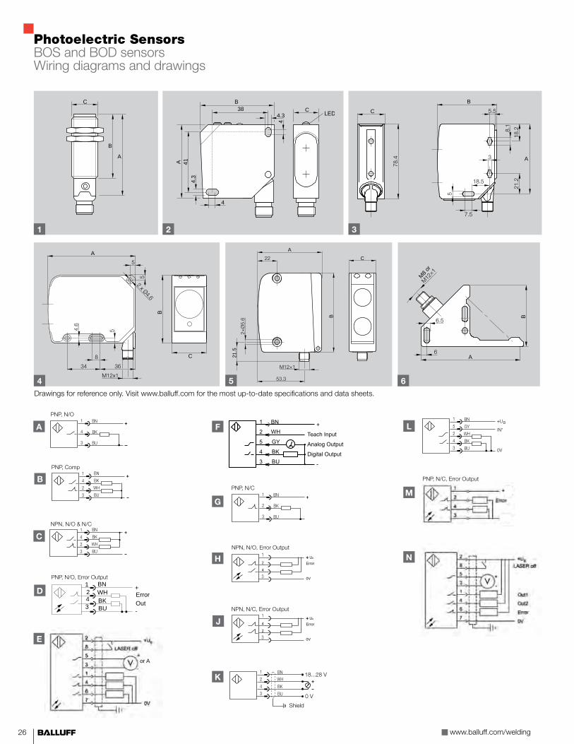
When a photoelectric sensor has to be used in a weld cell, it must be protected to survive in this extreme sensing environment. Success requires a degree of application expertise. Mechanical protection and bunkering must be applied to achieve acceptable sensor survivability. In addition, ambient weld smoke, weld debris, oil, and mist, as well as sensing distance, excess gain requirements, and precision parameters must be taken into account in the choice of a photoelectric sensor. However, with the appropriate sensor choice, mounting hardware, and connectivity, it is possible to apply a photoelectric in the weld cell environment.
Photoelectric SensorsBOS and BOD sensors
Order Code
Sensing Distance
Light Source
Output Logic Housing/Lens Material
Bunker Block Available
Wiring Diag.
Drawing Dimensions Connection
A B C D
Background Suppression - M18 Tubular, 10…30VDC
BOS014W 30…300 mm Visible Red PNP, Comp Ni CuZn / Glass n B 1 75 48 M18 M12
BOS019P 30…300 mm Visible Red PNP, NO Ni CuZn / Glass n A 1 75 48 M18 M12
BOS019N 30…300 mm Visible Red PNP, NO / Er-ror output
Ni CuZn / Glass n A 1 75 48 M18 M12
BOS010J 10…120 mm Visible Red PNP, NO Ni CuZn / Glass A 1 75 45 M18 M12
BOS0081 40…120 mm Visible Red PNP, Comp Ni CuZn / Glass B 1 82 82 20 23 M12
Diffuse - M18 Tubular, 10…30VDC
BOS01CA 300 mm Visible Red PNP, Comp Ni CuZn / Glass n B 1 75 48 M18 M12
BOS01E7 300 mm Visible Red PNP, NO Ni CuZn / Glass n A 1 75 48 M18 M12
BOS01E8 300 mm Visible Red PNP, NC Ni CuZn / Glass n G 1 75 48 M18 M12
BOS01CF 600 mm Visible Red PNP, Comp Ni CuZn / Glass n B 1 75 48 M18 M12
BOS01C1 600 mm Visible Red PNP, NO Ni CuZn / Glass n A 1 75 48 M18 M12
BOS01E3 600 mm Visible Red PNP, NC Ni CuZn / Glass n G 1 75 48 M18 M12
BOS010K 400 mm Visible Red PNP, NO Ni CuZn / Glass A 1 75 45 M18 M12
BOS0047 100 mm Visible Red PNP, NO Stn. Stl. / Glass n A 1 70 43.5 M18 M12
BOS001A 200 mm Visible Red PNP, NO Stn. Stl. / Glass n A 1 70 43.5 M18 M12
BOS001C 400 mm Visible Red PNP, NO Stn. Stl. / Glass n A 1 70 43.5 M18 M12
Background Suppression - Block, 10…30VDC
BOS0089 30…300 mm Visible Red PNP, Comp ABS / PMMA n B 2 50 50 17 M12
BOS0082 30…300 mm Visible Red NPN, Comp ABS / PMMA n C 2 50 50 17 M12
BOS008A 150…600 mm Infrared PNP, Comp ABS / PMMA n B 2 50 50 17 M12
BOS0083 150…600 mm Infrared NPN, Comp ABS / PMMA n C 2 50 50 17 M12
BOS008C 25…60 mm Class II Laser PNP, Comp ABS / PMMA n B 2 50 50 17 M12
BOS0084 25…60 mm Class II Laser NPN, Comp ABS / PMMA n C 2 50 50 17 M12
BOS008E 30…150 mm Class II Laser PNP, Comp ABS / PMMA n B 2 50 50 17 M12
BOS0085 30…150 mm Class II Laser NPN, Comp ABS / PMMA n C 2 50 50 17 M12
BOS008F 50…300 mm Class II Laser PNP, Comp ABS / PMMA n B 2 50 50 17 M12
BOS0086 50…300 mm Class II Laser NPN, Comp ABS / PMMA n C 2 50 50 17 M12
Background Suppression - Block, 10…30VDC
BOS018N 200…2000 mm Visible Red PNP, NO ABS / Glass A 3 80.5 60.2 28.5 M12
BOS0156 200…2000 mm Visible Red PNP, NO/Error output
ABS / Glass D 3 80.5 60.2 28.5 M12
BOS018U 200…2000 mm Visible Red PNP, NC ABS / Glass M 3 80.5 60.2 28.5 M12
BOS018P 200…2000 mm Visible Red PNP, Comp ABS / Glass B 3 80.5 60.2 28.5 M12
BOS018T 200…2000 mm Visible Red NPN, NO/Error output
ABS / Glass H 3 80.5 60.2 28.5 M12
BOS018W 200…2000 mm Visible Red NPN, NC/Error output
ABS / Glass J 3 80.5 60.2 28.5 M12
BOS018R 200…2000 mm Visible Red NPN, Comp ABS / Glass C 3 80.5 60.2 28.5 M12

25
Order Code
Sensing Distance
Light Source
Output Logic Housing/Lens Material
Bunker Block Available
Wiring Diag.
Drawing Dimensions Connection
A B C
Analog - Block, 10…30VDC
BOD0002 45...85 mm Class II Laser 0 - 10 VDC ABS/PMMA n K 2 50 50 17 M12
BOD0004 45...85 mm Class II Laser 0 - 10 VDC ABS/PMMA n K 2 50 50 17 M12
BOD0007 30…100 mm Class II Laser 4 - 20 mA / PNP, NO
ABS/PMMA n L 2 50 50 17 M12
BOD0008 80...300 mm Class II Laser 4 - 20 mA / PNP, NO
ABS/PMMA n L 2 50 50 17 M12
Analog - Block, 10…30VDC
BOD000U 200…2000 mm Class II Laser 0 - 10 VDC / (3) PNP, NO
Ana. Al./Glass E 4 90 70 35 M12
BOD0017 200…2000 mm Class II Laser 0 - 10 VDC / (3) NPN, NO
Ana. Al./Glass N 4 90 70 35 M12
BOD000W 200…6000 mm Class II Laser 0 - 10 VDC / (3) PNP, NO
Ana. Al /Glass E 4 90 70 35 M12
BOD000Y 200…6000 mm Class II Laser 0 - 10 VDC / (3) NPN, NO
Ana. Al./Glass N 4 90 70 35 M12
BOD0010 200…2000 mm Class II Laser 4 - 20 mA / (3) PNP, NO
Ana. Al./Glass E 4 90 70 35 M12
BOD0018 200…2000 mm Class II Laser 4 - 20 mA / (3) NPN, NO
Ana. Al./Glass N 4 90 70 35 M12
BOD0011 200…6000 mm Class II Laser 4 - 20 mA / (3) PNP, NO
Ana. Al./Glass E 4 90 70 35 M12
BOD0019 200…6000 mm Class II Laser 4 - 20 mA / (3) NPN, NO
Ana. Al./Glass N 4 90 70 35 M12
Analog - Block, 10…30VDC
BOD0015 100…600 mm Visible Red 1- 10 VDC / PNP, NO
Ana. Al./Glass F 5 90 73.2 30 M12
BOD0016 100…600 mm Visible Red 4 - 20 mA / PNP, NO
Ana. Al./Glass F 5 90 73.2 30 M12
BOD0013 200…2000 mm Class II Laser 1 - 10 VDC / PNP, NO
Ana. Al./Glass F 5 90 73.2 30 M12
BOD0014 200…2000 mm Class II Laser 4 - 20 mA / PNP, NO
Ana. Al./Glass F 5 90 73.2 30 M12
Thru-Beam, One Piece, "L" shaped, 10…30VDC
BWL001F 22 x 22 Infrared PNP, NO Stn. Stl./PMMA A 6 96 45.4 10.7 M12
BWL001H 22 x 22 Infrared PNP, NO Stn. Stl./PMMA A 6 83.5 45.4 10.7 M12
BWL001J 42 x 41 Infrared PNP, NO Stn. Stl./PMMA A 6 110 66 10.7 M12
BWL001K 42 x 41 Infrared PNP, NO Stn. Stl./PMMA A 6 110 66 10.7 M8
BWL001L 42 x 60 Infrared PNP, NO Stn. Stl./PMMA A 6 106 90 10.7 M12
BWL001M 42 x 60 Infrared PNP, NO Stn. Stl./PMMA A 6 106 90 10.7 M8
For wiring diagrams and drawings, see next page 26.
www.balluff.com/welding26
1 2 3
4
Photoelectric SensorsBOS and BOD sensorsWiring diagrams and drawings
����
���
�
��
�
�� ��������� ��
� �
��������� �� �
�
����������� �� �
�
F
B
PNP, Comp
A
PNP, N/O
C
NPN, N/O & N/C
1243
BNWHBKBU -
OutError+D
PNP, N/O, Error Output
C
A
B
B38
4
44.
341A
4.3C
A
B
C
5 6
A
B
C
21.5
A
B
M8 or
K
Shield
L
C
B
A
Drawings for reference only. Visit www.balluff.com for the most up-to-date specifications and data sheets.
E
or A
G
PNP, N/C
H 2
4
UB
Error
0V
NPN, N/O, Error Output
J 4
2
UB
Error
0V
NPN, N/C, Error Output
PNP, N/C, Error Output
M
N

27
Pressure SensorsFluid detection sensorsBalluff pressure sensors offer an impressive price/performance ratio and are suitable for a wide variety of applications and pressure ranges in factory automation. A large display and simple operating concept save time when configuring parameters. Balluff pressure sensors are versatile and space-saving, with display and connector that can be rotated independently of the flange. Other features include compact housing design, local pressure indicator, digital switching outputs, and available analog output.
Order Code Pressure Range Process Connection Output Logic Electrical Connection
BSP005C -14.5…145 1/4” NPT (2) PNP, NO or NC M12
BSP005H -14.5…145 1/4” NPT 0…10 VDC & PNP NO or NC M12
BSP005J -14.5…145 1/4” NPT 4…20 mA & PNP NO or NC M12
BSP000J 0…145 G1/4” (2) PNP, NO or NC M12
BSP000W 0…145 G1/4” 0…10 VDC & PNP NO or NC M12
BSP0016 0…145 G1/4” 4…20 mA & PNP NO or NC M12
BSP005E 0…1,450 1/4” NPT (2) PNP, NO or NC M12
BSP0010 0…1,450 G1/4” 0…10 VDC & PNP NO or NC M12
BSP0019 0…1,450 G1/4” 4…20 mA & PNP NO or NC M12
BSP005F 0…3,626 1/4” NPT (2) PNP, NO or NC M12
BSP0011 0…3,626 G1/4” 0…10 VDC & PNP NO or NC M12
BSP001A 0…3,626 G1/4” 4…20 mA & PNP NO or NC M12
Design Relative nominal pressureOverload pressure Burst pressure ≥
Permitted vacuum
Pressure sensors –1...2 bar 29 psi 2 bar 58 psi 4 bar 145 psi 10 bar
vacu
um p
roof
Pressure sensors –1...10 bar 145 psi 10 bar 290 psi 20 bar 508 psi 35 barPressure sensors 0...2 bar 29 psi 2 bar 58 psi 4 bar 145 psi 10 barPressure sensors 0...5 bar 73 psi 5 bar 145 psi 10 bar 218 psi 15 barPressure sensors 0...10 bar 145 psi 10 bar 290 psi 20 bar 508 psi 35 barPressure sensors 0...20 bar 290 psi 20 bar 580 psi 40 bar 1088 psi 75 barPressure sensors 0...50 bar 725 psi 50 bar 1450 psi 100 bar 2176 psi 150 barPressure sensors 0...100 bar 1450 psi 100 bar 2900 psi 200 bar 3626 psi 250 barPressure sensors 0...250 bar 3626 psi 250 bar 5802 psi 400 bar 6527 psi 450 barPressure sensors 0...400 bar 5802 psi 400 bar 9428 psi 650 bar 10153 psi 700 barPressure sensors 0...600 bar 8702 psi 600 bar 10878 psi 750 bar 11603 psi 800 bar
Switching function4-wire pressure sensors with switching output
4-wire pressure sensors with analog output
Adapter NPT 1/4"BAM01KTStainless steelG 1/4"NPT 1/4"
Process connection
Display and connection housing rotates 320°
Display and control panel
Drawings for reference only. Visit www.balluff.com for the most up-to-date specifications and data sheets.
www.balluff.com/welding28
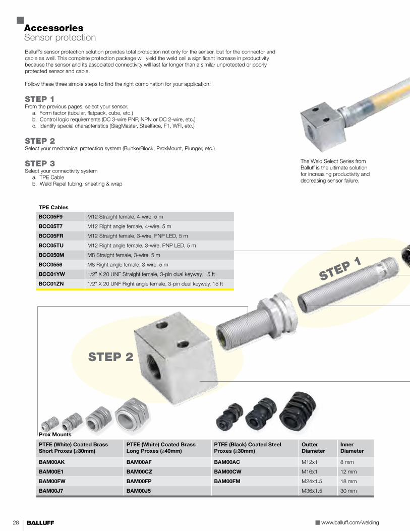
Balluff’s sensor protection solution provides total protection not only for the sensor, but for the connector and cable as well. This complete protection package will yield the weld cell a significant increase in productivity because the sensor and its associated connectivity will last far longer than a similar unprotected or poorly protected sensor and cable.
Follow these three simple steps to find the right combination for your application:
STEP 1From the previous pages, select your sensor. a. Form factor (tubular, flatpack, cube, etc.) b. Control logic requirements (DC 3-wire PNP, NPN or DC 2-wire, etc.) c. Identify special characteristics (SlagMaster, Steelface, F1, WFI, etc.)
STEP 2Select your mechanical protection system (BunkerBlock, ProxMount, Plunger, etc.)
STEP 3Select your connectivity system a. TPE Cable b. Weld Repel tubing, sheeting & wrap
TPE Cables
BCC05F9 M12 Straight female, 4-wire, 5 m
BCC05T7 M12 Right angle female, 4-wire, 5 m
BCC05FR M12 Straight female, 3-wire, PNP LED, 5 m
BCC05TU M12 Right angle female, 3-wire, PNP LED, 5 m
BCC050M M8 Straight female, 3-wire, 5 m
BCC0556 M8 Right angle female, 3-wire, 5 m
BCC01YW 1/2” X 20 UNF Straight female, 3-pin dual keyway, 15 ft
BCC01ZN 1/2” X 20 UNF Right angle female, 3-pin dual keyway, 15 ft
The Weld Select Series from Balluff is the ultimate solution for increasing productivity and decreasing sensor failure.
Prox Mounts
PTFE (White) Coated Brass Short Proxes (≥30mm)
PTFE (White) Coated Brass Long Proxes (≥40mm)
PTFE (Black) Coated Steel Proxes (≥30mm)
Outter Diameter
Inner Diameter
BAM00AK BAM00AF BAM00AC M12x1 8 mm
BAM00E1 BAM00CZ BAM00CW M16x1 12 mm
BAM00FW BAM00FP BAM00FM M24x1.5 18 mm
BAM00J7 BAM00J5 M36x1.5 30 mm
AccessoriesSensor protection
STEP 1
STEP 2

29
Weld Repel® Jacket M8 M12
BAM017E Clear tubing, 1/4" dia. x 50 ft (15 m)
BAM017H Clear tubing, 3/8" dia. x 50 ft (15 m)† SE
BAM017L Clear tubing, 1/2" dia. x 50 ft (15 m)††, * DE SE
BAM017N Clear tubing, 5/8" dia. x 50 ft (15 m)** DE
BAM017R Clear tubing, 3/4" dia. x 50 ft (15 m)
BAM017U Clear tubing, 1.5" dia. x 25 ft (15 m)
BAM017Z Clear tubing, 2" dia. x 25 ft (15 m)
* Recommended for use with M12 (micro) single ended cables** Recommended for use with M12 (micro) double ended cables† Recommended for use with M8 (nano) single ended cables†† Recommended for use with M8 (nano) single ended cables
SlagMaster® recommended. See pages 10-11.
Weld Repel® Wrap
BAM0183 1" wide x 12 ft Clear wrap
BAM0182 2" wide x 36 ft Clear wrap
Weld Repel® Area Protection
BAM0179 3 ft x custom length in ft
BAM017A 3 ft x 3 ft sheet
Bunker Block® II without positive stop for direct sensor mounting
Copper Plated Steel Description
BAM00A4 M8 sensors
BAM00C6 M12 sensors
BAM00F5 M18 sensors
BAM00HR M30 sensors
Bunker Block®
Machined AL Prox Mount Required Description
BAM00EJ BAM00AF M8 sensors (40 mm+)
BAM00EU BAM00CZ M12 sensors (40 mm+)
BAM00HE BAM00FP M18 sensors (40 mm+)
BAM00JP BAM00J5 M30 sensors (40 mm+)
BAM00EK BAM00AK M8 sensors (short)
BAM00EW BAM00E1 M12 sensors (short)
BAM00HF BAM00FW M18 sensors (short)
BAM00JR BAM00J7 M30 sensors (short)
STEP 3
PTFE recommended.See pages 12-13.

www.balluff.com/welding30
Aluminum Clamp with Positive Stop
BAM00A7 AL clamp for M8 sensors
BAM00CF AL clamp for M12 sensors
BAM00FC AL clamp for M18 sensors
BAM00HW AL clamp for M30 sensors
Heavy Duty Prox Actuator Plunger
BAM015K Prox plunger for M12 sensors
WELD Jacket
WELD-JACKET-1/2" Silicone & fiberglass 1/2" diameter (by the foot)
WELD-JACKET-3/4" Silicone & fiberglass 3/4" diameter (by the foot)
Balluff offers many accessories designed to survive in the welding environment. These offerings are very effective at protecting and increasing sensor and connectivity life. Covers, caps, plungers, and clamps are all designed to help protect the sensor from damage. Metal connectivity accessories allow for heavy duty applications in the harshest environments, while Weld Jacket is another option in the fight to protect cables from damage. All of the products listed below will help reduce sensor failure and increase sensor life expectancy.
R01 Flatpack Sensor Accessories
BAM00NK Over-the-top, retro-fit bunker block
BAM00NL Socket style bunker block (for new installations)
BES02YW PTFE protective cover
Q40 & 26K Sensor Accessories
BAM00JY Q40 Metal mounting bracket
BAM00K0 Q40 AL protection cover w/PTFE face cover
BAM00K1 Q40 PA6 protection cover
BAM0155 BOS 26K Bunker Block®
Air Blow-off Accessories & Air Knife
BAM00PY Air blow-off for M12 sensors
BAM00R9 Air blow-off for M18 sensors
BAM0041 Air knife assembly
AccessoriesSensor protection
Protective Caps
BAM0156 Ceramic for M12 sensors
BAM0157 Ceramic for M18 sensors
BES 30-CERAMIC-CAP-1 Ceramic for M30 sensors
BAM00C3 PTFE caps for Prox Mounts (M12)
BAM00ER PTFE caps for Prox Mounts (M16)
BAM00HC PTFE caps for Prox Mounts (M24)
BAM00JM PTFE caps for Prox Mounts (M36)
BAM0123 Protective glass lens cap (M18)

31
Industrial Networks and Connectivity Products
In welding, equipment is required to survive in rugged and harsh environments, and control components are not excluded. Short circuits, weld slag and impact damage inevitably happen to products installed on equipment. The ability to hold up to these problems, provide easy to troubleshoot diagnostics and easy to see indication can reduce downtime and make issues easier to troubleshoot over traditional I/O devices and architectures.
Clearly visible status LEDsn Speedup troubleshootingn Short circuit indication
IP67 Addressingn Push buttons or rotary dialsn Quick changeout, no PCs or devices required to address
Innovative housing designn Extreme durabilityn Low-profile
Multiple Protocols
Powerful and Safe Outputsn Up to 2 Ampsn Easy overload troubleshooting
Detailed Level of Diagnosticsn Port level diagnosticsn Shorts, voltage, overload, etc.
For full product offering, download the latest catalog at
www.balluff.com/connectivity
Description Inputs Outputs
Input Only 16 0 BNI004M BNI0001
Output Only 0 8 BNI0015 BNI0002
Input / Output 8 8 BNI0017 BNI0004
Configurable 16 max 16 max BNI004F BNI0003

USA Balluff Inc. 8125 Holton Drive Florence, KY 41042 Phone: (859) 727-2200 Toll-free: 1-800-543-8390 Fax: (859) 727-4823 E-Mail: [email protected]
Canada Balluff Canada, Inc. 2840 Argentia Road, Unit #2 Mississauga, Ontario L5N 8G4 Phone: (905) 816-1494 Toll-free: 1-800-927-9654 Fax: (905) 816-1411 E-Mail: [email protected]
Mexico Balluff de Mexico S.A. de C.V Prol. Av. Luis M. Vega #109 Col. Ampliacion Cimatario Queretaro, QRO 76030 Phone: (++52 442) 212-4882, 224-3583, 224-3171 Fax: (++52 442) 214-0536 E-Mail: [email protected]
Linear Position and MeasurementMicropulse® transducers, magnetic linear encoder system, inductive displacement system, inductive distance sensors, magnetoinductive distance sensors, capacitive distance sensors, photoelectric distance sensors, ultrasonic sensors
Networking and ConnectivityConnectors and connection cables, valve connectors, passive splitter boxes, active splitter boxes, IO-Link, bus systems (Profibus, Profinet, CC-Link, DeviceNet, EtherNet), inductive couplers, power supplies, electrical devices
AccessoriesBrackets and mountings, assembly system BMS
Fluid DetectionPressure sensors, capacitive sensors for level detection
Industrial IdentificationIndustrial RFID systems, vision sensors
Connect with us online!
Scan the QR Code to visit our social media page at:www.balluff.com/socialmedia
www.balluff.com
Sensing, Networking, and Identification for Industrial Automation
Object DetectionInductive sensors, cylinder sensors, magnetic field sensors capacitive sensors, ultrasonic sensors, photoelectric sensors, fiber optic devices, fiber optics, angle sensors, through-beam fork sensors, optical window sensors, light grids, contrast sensors, luminescence sensors, color sensors, mechanical and inductive single and multiple position switches
Doc.
No.
886
764/
Mat
. No.
219
837
E •
Editi
on 2
011-
11 •
Pro
duct
spec
ifica
tions
, ava
ilabi
lity,
and
pric
ing
are
subj
ect t
o ch
ange
with
out n
otic
e.