Embed Size (px)
Citation preview
WELDING INFORMATION SYSTEM - DESIGN, OPERATIONS, METHODS
by
DANIEL BLAIR JENNINGS
B.A.Sc, The University of British Columbia, 1989 M-A.Sc, The University of British Columbia, 1991
A THESIS SUBMITTED IN PARTIAL F U L F I L L M E N T OF
T H E REQUIREMENTS FOR T H E D E G R E E OF
MASTER OF APPLIED SCIENCE
in
T H E F A C U L T Y OF G R A D U A T E STUDIES
(Civil Engineering)
We accept this thesis as conforming
to the required standard
T H E UNIVERSITY OF BRITISH C O L U M B I A
April 1991
(c) Daniel Blair Jennings, 1991
In presenting this thesis in partial fulfilment of the requirements for an advanced degree at the
University of British Columbia, I agree that the Library shall make it freely available for reference
and study. I further agree that permission for extensive copying of this thesis for scholarly
purposes may be granted by the head of my department or by his or her representatives. It is
understood that copying or publication of this thesis for financial gain shall not be allowed without
my written permission.
Department of
The University of British Columbia
Vancouver, Canada
Date L 2.2^ ,
ABSTRACT
This thesis encompasses a Welding Information System for Design, Operations, and Methods
(WISDOM). In essence, the WISDOM project aimed at research and development of an
innovative and comprehensive information collection on welding in close cooperation with
industry utilizing modern micro-computer techniques of information review, retrieval, storage,
updating, and transfer. Emphasis is placed on new and more efficient methods of knowledge
communication, pursuing the idea of exploring knowledge (in contrast to rehearsing recipes).
The development of this project concentrated on the following three main topics:
1. Background information on steel metallurgy and welding
2. Analysis and Design Methods for Welded Connections
3. Code Requirements of Welds
Preliminary research on the WISDOM project involved communications with industry to
determine primary objectives. The need for an information system on welding was unques
tionably apparent. The knowledge base is supplemented with graphic images and analysis and
design programs. It is hoped that the information in this system will be delivered to the
engineer in an efficient and useful manner. The priority here is to raise welding awareness
while promoting efficient welded design. In addition, we hope that the WISDOM system will
close the ever widening gap between the design engineer and the fabricator.
In the most general sense, the primary objective of the WISDOM project was to produce an
integrated self-paced teaching tool for both engineering professional and student alike. The
versatility of the system is maintained by presenting the information in modular form. Screen
graphics oriented learning modules encourage the user to become more involved in the learning
process than more conventional teaching methods allow. Analysis and design modules promote
rapid and efficient connection design in a more consistent and professional manner. A smooth
transition from the learning environment to engineering practice is envisioned by providing
realistic design tools with a transparent background.
ii
TABLE OF CONTENTS
ABSTRACT ii
TABLE OF TABLES x
lWhy W.I.S.D.O.M? 1
1.1 WISDOM Objectives 2
1.2 Hardware and Software Details 4
1.3 Hypertext Development 5
1.4 W I S D O M - A Quick Tour 7
1.5 Target Group and Benefits of the Project 8
2 About Welded Construction 10
2.1 Generating Welding Awareness 10
2.2 Advantages of Welded Construction 11
2.3 Weld Strength 12
2.4 Weld Quality 12
2.5 Designing For Welding 14
2.6 Designing Welded Buildings : 15
2.7 Designing Welded Bridges 16
2.8 Welding Quickens Erection Time 16
3 Metallurgy and Steel 18
3.1 Production of Steel 18
3.1.1 Blast Furnace 19
3.1.2 Cast Iron 20
3.1.3 Basic Oxygen Furnace 21
3.1.4 Open Hearth Furnace 21
3.1.5 Electric Furnace 22
3.1.6 Crucible Furnace 23
3.1.7 Induction Furnace 23
3.1.8 Vacuum Furnace 23
3.1.8.1 Vacuum Arc Furnace 24
3.1.8.2 Vacuum Induction-Type Furnace 24
iii
3.1.8.3 Vacuum Stream Degassing 25
3.1.8.4 Ladle degassing 25
3.1.9 First Solid Forms of Steel 25
3.1.10 Processing Metals 26
3.2 The Micro-Structure of Iron and Steel 27
3.2.1 Formation of the Solid Phase 27
3.2.2 Iron, Carbon, and Steel 28
3.2.2.1 The Crystal Structure of Iron 29
3.2.2.2 The Phase Diagram 29
3.2.2.3 The Iron-Carbon Phase Diagram 31
3.2.3 Time-Temperature-Transformation (TTT) Curves 33
3.2.4 Continuous Cooling Transformation (CCT) Diagrams 34
3.2.5 H A Z Microstructures in Steel Welds 35
3.3 Welding Metallurgy in Structural Steels .'. 36
4 Welding Basics 41
4.1 History of Welding 41
4.2 Basic Weld Processes 42
4.2.1 Electric Arc Welding 43
4.2.2 Resistance Welding 45
4.2.3 Oxyacetylene Gas Welding 45
4.2.4 Electroslag Welding 45
4.2.5 Stud Welding 46
4.3 Basic Welding Types 46
4.3.1 Groove Welds 46
4.3.2 Complete Joint Penetration Grooves 47
4.3.3 Partial Joint Penetration Grooves 48
4.3.4 Fillet Welds 48
4.3.5 Plug Weld 49
4.4 Terminology in Welded Joints 50
4.5 Welding Positions 50
iv
4.6 Welding Standards 50
5 Wettability of Steels 51
5.1 Weldability 51
5.2 Base Procedure on Actual Composition 53
5.3 Weld Quality 53
5.4 Weld Cracks and Their Prevention 54
5.4.1 Factors that Affect Weld Cracking During Welding 54
5.4.2 Factors that Affect Cracking in the Heat-Affected Zone 54
5.4.3 Factors that Affect Welded Joints Failing in Service 55
5.4.4 Items to Control Weld Cracking 55
5.5 Tack Welds 55
5.6 Welding Thin Plates 56
5.7 Welding Thick Plates 56
5.7.1 Fillet Welds on Thick Plates 57
5.7.2 Groove Welds on Thick Plates 58
5.8 Internal Cracking in Welds 59
5.9 Underbead Cracking 60
5.10 Reasons to Preheat 61
6 Maintaining Control Over Welding 63
6.1 Residual Stresses 63
6.1.1 Discussion of Residual Stresses 64
6.1.2 Residual and Reaction Stresses in a Butt Weld 65
6.1.3 Residual Stress in Columns 66
6.1.4 Residual Stress in Flexural Members 67
6.2 Shrinkage and Distortion 68
6.2.1 Welding Factors That Cause Movement 69
6.2.2 Weld Metal Shrinkage 69
6.2.3 Base Metal Shrinkage 70
6.2.4 Fundamental Modes of Distortion 71
6.2.4.1 Transverse Shrinkage of Butt Welds 71
v
6.2.4.2 Transverse Shrinkage of Fillet Welds 74
6.2.4.3 Longitudinal Shrinkage 74
6.2.4.4 Longitudinal Bending Distortion 75
6.2.4.5 Angular Distortion 76
6.2.4.6 Buckling Distortion 78
6.2.5 Control of Weld Shrinkage and Distortion 78
6.2.5.1 Do Not Overweld 79
6.2.5.2 Use as Few Weld Passes as Possible 79
6.2.5.3 Place Welds Near The Neutral Axis 79
6.2.5.4 Balance Welds Around the Neutral Axis 79
6.2.5.5 Welding Technique 79
6.2.5.6 Make Shrinkage Forces Work in the Desired Direction 80
6.2.5.7 Balance Shrinkage Forces With Opposing Forces 80
6.2.5.8 Welding Sequence 81
6.2.5.9 Removal of Shrinkage Forces During or After Welding 81
6.2.5.10 Reduce the Welding Time 82
6.2.5.11 Effect of High Welding Speeds 82
6.2.5.12 Type and Size of Electrode 83
6.2.5.13 Degree of Restraint 84
6.3 Summary and Check List 85
6.3.1 Notes on Transverse Shrinkage and Distortion 85
6.3.2 Notes on Reducing Angular distortion 85
6.3.3 Notes on Bending of Longitudinal Members 86
6.3.4 Notes on Assembly procedures to Control Distortion 86
6.4 Lamellar Tearing 87
7 Designing For Welding 90
7.1 Steel Grade Selection 90
7.1.1 Steel Grade Availability 91
7.1.2 Steel Grade Strength 91
7.1.3 Steel Grade Ductility 91
vi
7.1.4 Steel Grade Wettability , 92
7.1.5 Steel Grade Service Conditions 93
7.1.6 Steel Grade Environmental Conditions 93
7.2 Design Considerations for Improved Service Behavior 94
7.2.1 Design - Service Conditions 94
7.2.2 Improvement of Service Conditions 95
7.2.3 Weld Strength Computations 96
7.3 Detailing to Achieve Practical Welded Fabrication 99
7.3.1 Failure to Provide a Path for Transverse Forces 100
7.3.2 Failure to Provide a Component When a Force Changes Direction 101
7.3.3 Failure to Recognize a Major Force Resulting From a Load 104
7.3.4 Failure to Alter Detailing When Welding Replaces Riveting 105
7.3.5 Failure to Recognize Strain Compatibility 105
7.3.6 There are No Secondary Members in a Welded Design 106
7.3.7 Do Not Rely on Welder Skill in Place of Proper Design 108
7.3.8 Do Not Place Welds in Regions of Bending 109
7.3.9 Failure by Compressive Fatigue Load 110
7.3.10 Failure to Design Against Lamellar Tearing I l l
7.3.11 Redundancy With Diagonal Stiffeners 112
7.3.12 Failure to Consider Not-in-Service Loads 113
7.3.13 Failure to Understand Matching Electrode Conditions 113
8 Determine Weld Size 115
8.1 Welding Electrode - Base Metal Matching Conditions 115
8.2 Design of Complete Joint Penetration Groove Welds 116
8.3 Design of Partial Joint Penetration Groove Welds 117
8.4 Design of Fillet Welds 118
8.5 Design of Plug and Slot Welds 121
8.6 Determining Stresses on Welds 122
8.6.1 Allowable Stresses or Factored Resistances 122
8.6.2 Stresses in Butt Welds 123
vii
8.6.3 Stresses in Fillet Welds 123
8.6.4 Example: Load Parallel to Fillet Welds 124
8.6.5 Example: End Fillets in Lap Joint 125
8.6.6 Example: A l l Around Weld 125
8.6.7 Example: Fillet Welds in Bending and Shear 125
8.7 Welds Subjected to Torsion 126
8.8 Weld Sizing Through "Weld-Line" Analysis 127
9 Flexible Connections 131
9.1 General Considerations for Flexible Connection Design 131
9.2 Standard Flexible Connections 131
9.2.1 Framed Beam Shear Connections 132
9.2.1.1 General Design Considerations for Framed Beam Shear Connections 132
9.2.1.2 Double angle connection 133
9.2.1.2.1 Design Considerations for the Double Angle Connection 133
9.2.1.2.1.1 Instantaneous Centers and Eccentrically Loaded Weld Groups 135
9.2.1.3 Single Angle Connection 136
9.2.1.3.1 Design Considerations for the Single Angle Connection 137
9.2.1.4 Tee Connection 137
9.2.1.4.1 Design Considerations for the Tee-Type Connection 138
9.2.1.5 Flexible End Plate Connection 138
9.2.1.6 Single Side Web Plate Connection 139
9.2.1.6.1 Design Considerations for Single Side Plate Connections 139
9.2.1.7 Framed Beam Shear Connection Design Module 141
9.2.2 Flexible Seated Shear Beam Connections 142
9.2.2.1 Flexible Seated Shear Beam Connection Design Considerations 142
9.2.2.2 Flexible Seated Shear Beam Connection Design Module 144
9.2.3 Stiffened Seated Shear Beam Connections 145
9.2.3.1 Stiffened Seated Shear Beam Connection Design Considerations 145
9.2.3.2 Stiffened Seated Shear Beam Connection Design Module 147
viii
9.3 Non-Standard Connections 147
9.3.1 Non-Standard - In Plane Eccentricity 148
9.3.1.1 Design Module for In Plane Eccentricities 148
9.3.2 Non-Standard-Out of Plane Eccentricity 149
9.3.2.1 Design Module for Out of Plane Eccentricities 150
9.3.3 Direct Beam Web Connections 151
9.3.4 Bearing Pad Connections 151
10 Moment Connections 153
10.1 Rigid and Semi-Rigid Connections 154
10.2 Column Stiffeners 155
10.2.1 S16.1-M89 21.3 Restrained Members 156
10.2.2 Test Comparison of Stiffener Types 157
10.3 General Recommendations for Welded Rigid Connections 158
10.4 Built Up Column Sections 160
ACKNOWLEDGEMENT 162
GLOBAL REFERENCES 163
ix
TABLE OF TABLES
Table_l: Carbon Percentages in Iron and Steel 29
Table_2: The History of Welding 41
Table_3: Preferred Analysis of Carbon Steel for Good Weldability 52
TAble_4: Critical Defect Size Chart 93
Table_5: Effective Throat Thickness (mm) for Tension and Shear 117
x
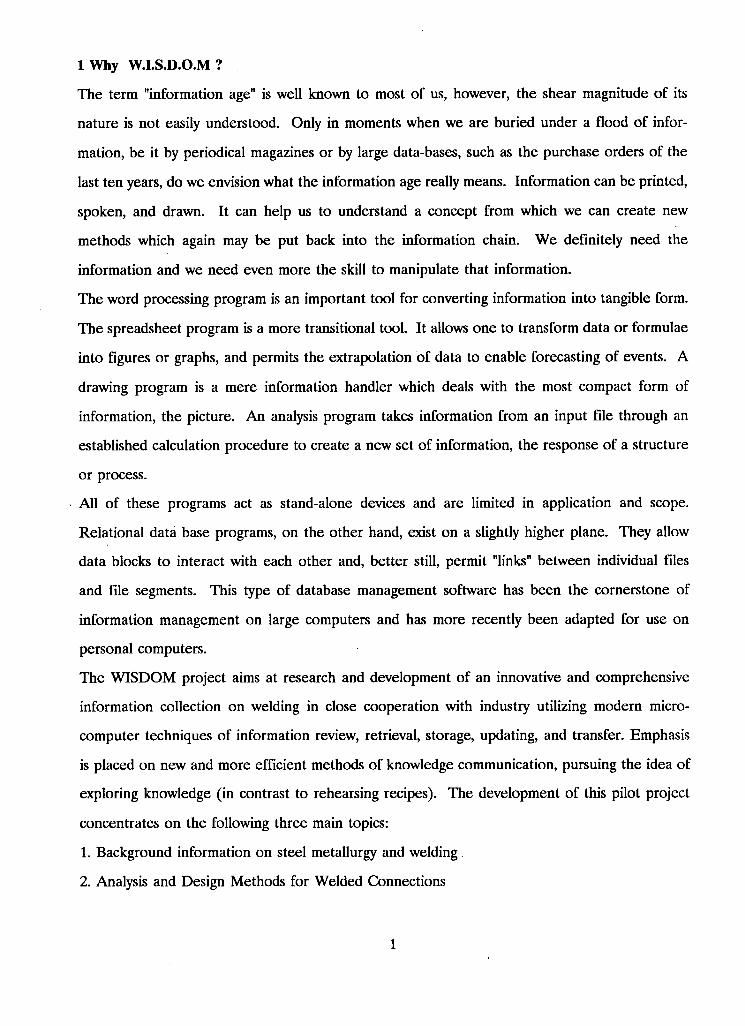
lWhy W.I.S.D.O.M?
The term "information age" is well known to most of us, however, the shear magnitude of its
nature is not easily understood. Only in moments when we are buried under a flood of infor
mation, be it by periodical magazines or by large data-bases, such as the purchase orders of the
last ten years, do we envision what the information age really means. Information can be printed,
spoken, and drawn. It can help us to understand a concept from which we can create new
methods which again may be put back into the information chain. We definitely need the
information and we need even more the skill to manipulate that information.
The word processing program is an important tool for converting information into tangible form.
The spreadsheet program is a more transitional tool. It allows one to transform data or formulae
into figures or graphs, and permits the extrapolation of data to enable forecasting of events. A
drawing program is a mere information handler which deals with the most compact form of
information, the picture. An analysis program takes information from an input file through an
established calculation procedure to create a new set of information, the response of a structure
or process.
A l l of these programs act as stand-alone devices and are limited in application and scope.
Relational data base programs, on the other hand, exist on a slightly higher plane. They allow
data blocks to interact with each other and, better still, permit "links" between individual files
and file segments. This type of database management software has been the cornerstone of
information management on large computers and has more recently been adapted for use on
personal computers.
The WISDOM project aims at research and development of an innovative and comprehensive
information collection on welding in close cooperation with industry utilizing modern micro
computer techniques of information review, retrieval, storage, updating, and transfer. Emphasis
is placed on new and more efficient methods of knowledge communication, pursuing the idea of
exploring knowledge (in contrast to rehearsing recipes). The development of this pilot project
concentrates on the following three main topics:
1. Background information on steel metallurgy and welding
2. Analysis and Design Methods for Welded Connections
1
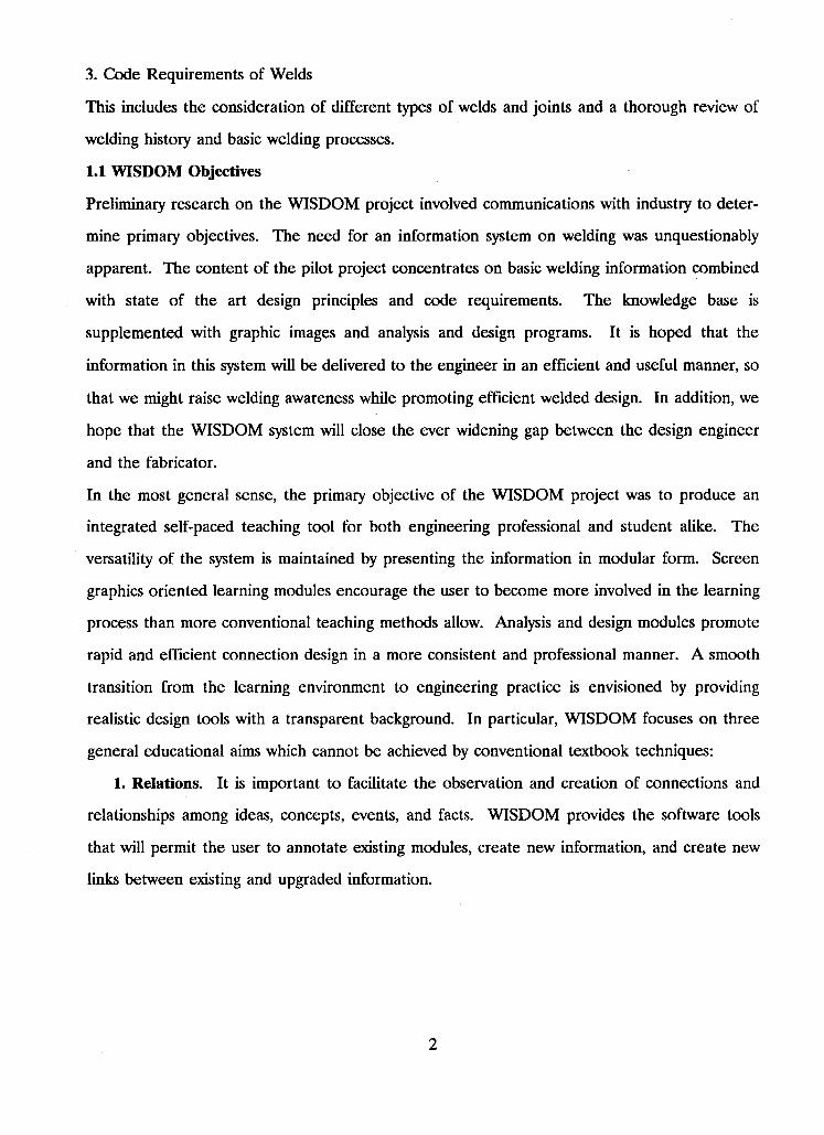
3. Code Requirements of Welds
This includes the consideration of different types of welds and joints and a thorough review of
welding history and basic welding processes.
1.1 WISDOM Objectives
Preliminary research on the WISDOM project involved communications with industry to deter
mine primary objectives. The need for an information system on welding was unquestionably
apparent. The content of the pilot project concentrates on basic welding information combined
with state of the art design principles and code requirements. The knowledge base is
supplemented with graphic images and analysis and design programs. It is hoped that the
information in this system will be delivered to the engineer in an efficient and useful manner, so
that we might raise welding awareness while promoting efficient welded design. In addition, we
hope that the WISDOM system will close the ever widening gap between the design engineer
and the fabricator.
In the most general sense, the primary objective of the WISDOM project was to produce an
integrated self-paced teaching tool for both engineering professional and student alike. The
versatility of the system is maintained by presenting the information in modular form. Screen
graphics oriented learning modules encourage the user to become more involved in the learning
process than more conventional teaching methods allow. Analysis and design modules promote
rapid and efficient connection design in a more consistent and professional manner. A smooth
transition from the learning environment to engineering practice is envisioned by providing
realistic design tools with a transparent background. In particular, WISDOM focuses on three
general educational aims which cannot be achieved by conventional textbook techniques:
1. Relations. It is important to facilitate the observation and creation of connections and
relationships among ideas, concepts, events, and facts. WISDOM provides the software tools
that will permit the user to annotate existing modules, create new information, and create new
links between existing and upgraded information.
2
2. Visualization. Wisdom enhances the users ability to visualize and perceive complex and
dynamic phenomena which might otherwise need extensive analytical calculations and graphical
or motion picture representations. The full impact of this educational aim may not be realized
until further additions are made to the pilot project.
3. Exploration. WISDOM encourages exploration of an information-rich environment such
that students may discover ideas, themes, and facts on their own.
The following module types are typical of the WISDOM pilot project:
1. Background welding information modules
2. Specific welding design modules
3. Spreadsheet modules with code related requirements and design guides
4. Hypertext module with background information
Besides the above stated educational objectives, WISDOM has several technological aims:
1. Reusability. The software industry and the academic research community tolerate by far
too much wasteful reinvention of code. A large portion of development time for each of the
thousands of software products is spent writing code that performs functions already implemented
in many other packages. While this competition is worthwhile for fine tuning special product
areas, WISDOM uses large portions of commercially available code and remains accessible to
future developers.
2. Consistency. An important feature of the WISDOM shell is to provide a consistent screen
oriented user interface across modules, such that the selection of choices and commands, and the
creation and following of links operate identically in all applications. This consistency is extended
deep into the coding, such that even data structures and procedures can be easily understood by
other developers.
3. Modularity. If a program system like WISDOM is developed by more than one person it
is mandatory to be not only consistent, but modular. The modularity facilitates partial devel
opment and further extensions. Modules have to be created as stand-alone applications and one
must by able to test them without interference with other developers. The modules must have
the ability to be integrated into the system with little effort.
3
1.2 Hardware and Software Details
Hardware
The WISDOM environment was developed for use on IBM or compatible machines with 640k
memory, hard-disk, and a MICROSOFT compatible mouse. For screen display, V G A is pre
ferable but not required as E G A and C G A will work with minimal screen distortion. Although
it is possible to use monochrome display, color is far more desirable. In addition, the software
is compatible with UNLX type work stations (SUN, APPOLLO, NEXT).
Software Standards
The operating system for the WISDOM environment is PC-DOS. A l l software was developed
in C and C++ in order to be compatible with further hardware development. C+ + is essentially
object-oriented C. Numeric files are in WK1-format with numbers in IEEE-format. Text files
are in ASCII-format while intermediate and configuration files are in binary format. Software
functions were purchased or licensed whenever possible and new modules, if fundamental, were
contracted out.
User Interface Standard
WISDOM implements a window-like screen appearance with two-level menu choices that collapse
after selection. Menus allow the user to examine all available commands and to then execute
any one of them by making a choice with a mouse or other pointing device, or by typing the first
letter of the menu choice. Al l menu titles are displayed at the top of the screen in an entity
called the menubar. The windows are used to divide the screen into (overlapping) areas. The
screen-mode switches from character-oriented to graphics-oriented whenever necessary.
Software Background
WISDOM utilizes a number of commercial programming tools. TURBO C by B O R L A N D
International was used throughout the WISDOM project as the primary programming language.
This dialect of C language is a structured, modular, compiled, general-purpose language tradi
tionally used for systems programming. It is portable, so one can easily transfer application
programmes from one system to another. TURBO C is relatively inexpensive, yet fast and
powerful. It can be used through a so-called integrated environment, which combines editor,
compiler and linker. However, larger programme modules must be handled in the command line
4
mode. As the additional libraries, such as C-scape and CB-Tree, were rather voluminous, mostly
the command line mode was used.
C-scape
C-scape is a collection of functions for controlling the user interface of C programmes. With
this library of C routines one can create and modify virtually any type of text or data entry screen.
The C-scape library is portable and available for many PC and mini-computer operating systems
(DOS, OS/2, UNIX, etc.). Its unique object oriented approach to programming enables the user
to achieve high efficiency during developmental work.
PowerCell
PowerCell is a commercially available collection of functions, similar to C-Scape, with which one
can construct a spreadsheet programme. We aimed at LOTUS 1-2-3 emulation and, in fact,
achieve this excluding the graphics, as the graphics part will be appended externally. Current
work concentrates on implementation of engineering specific functions not existent in LOTUS.
The previously used spreadsheet compiler was discarded, but can be revived for special tasks.
CB-Tree
CB-Tree is a collection of C functions which handle balanced binary tree data organization. The
balanced binary tree is an improvement to the more classical binary tree which tended to be
unbalanced when the sample size was small. The balanced tree permits optimal information
storage and retrieval with the small number of records associated with the WISDOM system.
PCX Programmer's Toolkit
The P C X Programmer's Toolkit is a collection of C functions which handle the capture and
output of bit-mapped screen images. The toolkit permits the generation of a window border,
whose size is dependent on the image, to define the screen area used for P C X display.
13 Hypertext Development
The hypertext module is the focal point of the WISDOM development. After intensive market
research and testing of existing hypertext programmes, it became necessary to pursue the
development of a specialized hypertext system which met all our needs. Many parts are incor
porated into the complete hypertext system, WISDOM.
5
The database is the backbone of the hypertext system. Most database functions stem from the
CB-TREE function library. Therefore, fast access, retrieval, update, and storage is secured. The
index is organized in a balanced tree which, for our application, is faster then the older binary
tree approach. There are two basic files which make up the hypertext-database: the index file
and the record file. The hypertext programme implements a search and retrieval mode that
searches the index file for the desired record and then directly accesses the main data-file for its
retrieval. Additions to the main data-file, as well as to the index file, are handled by the hypertext
programme. The user does not recognize that he/she is basically manipulating a database when
using the hypertext and, of course, you don't have to be a programmer to use the system.
Text display is one of two modes used by the hypertext system to present information. This
mode allows the user to view the hypermedia text-base in text format while any figures require
the P C X format. Furthermore, in the text display mode the user can establish and use links to
other text, figures, and even programmes.
PCX format is required by the hypertext system to display scanned and or drawn pictures. This
format is a widely spread file format used by popular programmes such as PC-Paintbrush. For
most quality drawing packages there exists file conversion programmes to create the P C X format.
As the pixel image of the screen is stored in these files, the picture is dependent on the graphics
adapter used. Therefore, slight distortions of the images will be encountered when the pictures
are created/scanned and shown on different adapters (i.e. origin V G A show on E G A results in
slightly stretched pictures). These problems are unavoidable but minor.
The C-scape based text editor is fully integrated in the hypertext system with mouse controlled
menus and cursor. Most of the standard block commands have been implemented to maintain
consistency with other text editors. In addition, it can import external ASCII type files into the
WISDOM hypertext system to support the creation of new topics.
A simple graphics editor or paint programme is being conceptually developed. The motivation
for having a custom graphics editor is that it can be used as a simple integrated sketching tool.
This editor will be object oriented and will use for storage the PCX-file format. This module is
not implemented yet.
6
The interactive linker allows the creation of active links to text portions, to screen images in
P C X format, and to other stand-alone computer programmes. The linking feature represents the
most important characteristic of the WISDOM system as it separates conventional data bases and
text editors from an interactive hypertext system. With this feature one can create cross refer
enced, non-sequential, logically linked, innovative knowledge and skill bases. In future this type
of "pre-digested" knowledge collection will probably rival conventional methods such as books,
seminars, and videos.
The script facility allows for "hard-wired" training sessions. The user can just step through a
predetermined path of text, figures, programmes, and exercises. The script facility will be very
useful to educators and invaluable in training sessions. Another possible use of the script facility
is the self-recording feature. The user can easily create demo sessions, either from an existing
hypertext base or from his own text and programme material. This enables many new and exciting
possibilities. The current WISDOM version does not yet contain the script facility, but the
concept has been tested and optimized.
A new product on the software market will permit the rapid development of a custom spread
sheet. This spreadsheet will utilize a file format and user interface that is basically compatible
with the industry standard, LOTUS 1-2-3. However, the implemented functions will be adjusted
to the needs of the engineers in order to keep the spreadsheet compact. To improve the inte
gration to the WISDOM package some features go beyond the LOTUS capabilities. For example
one will be able to load the programme with specifying attributes, which means one can
automatically retrieve an initial work template.
Most of the analysis modules are spreadsheet based. Using the formatted spreadsheet as
introduced by Navin and Stiemer [NAVI89] the worksheets are LOTUS compatible but
implemented in the custom spreadsheet. Other modules are written in TURBO C when iteration
methods and heavy number crunching require a faster execution time.
1.4 WISDOM - A Quick Tour
A sample of the WISDOM environment is provided here to highlight some of its features.
7
The opening screen, as you must have seen to get to this point, lists available topics from the
chosen data base. Any of the topics or menu choices may be pointed to and clicked on with the
mouse. Choice of a topic will initiate a search and retrieval of the desired record. Choice of a
menu will bring down a sub-menu providing further related options. As an example, you can
click onto the SCRIPT selection from the menu-bar. The sub-menu shows all the new choices
for generating a script.
Suppose we are interested in double angle connections. From the main menu we can click onto
many topics for related information. Pointing and clicking onto the link provided here,
@1[09.2.1.2 Double Angle Connections], brings up the main information module on double angle
connection. If you clicked onto this link, you would have discovered a new screen with many
new options to further the quest for knowledge. You could link to design considerations for
information about designing the connection or go straight to the design module. Furthermore,
at any time, you can edit the current screen or create new links to other components such as
text modules, graphic images, or other external design modules. Pointing and clicking onto
@1 [FLEX1.PCX] illustrates the result of linking to a double angle connection image.
Choice of a design program, for example @ 1 [ M A P L C A L C . E X E b_to_cf], would bring up a
spreadsheet in the Maplcalc environment. The user may alter cell inputs to generate a connection
design while in this environment. The user also has the power to completely alter the program,
so be cautious. The spreadsheet environment may be exited in the usual manner and the
WISDOM environment will then automatically reappear.
The above very brief tour should have just got you warmed up. You should now be ready to
experiment with the system at your own convenience.
1.5 Target Group and Benefits of the Project
The main target groups of WISDOM are the practicing engineers and the university students,
who wish to specialize in this area. Using such a tool which is based on explorational techniques
of education does not require sitting in seminar sessions or attending rigidly scheduled classes.
A survey of representative consulting engineers and fabricators indicated a definite need for an
up-to-date, self-paced, learning and application tool for welding. Trying to close the ever widening
gap between consultant and fabricator seems to be a timely task.
8
Currently none of the Canadian universities offer an undergraduate civil engineering core course
which contains welding as a single specialized topic. It is not expected that this type of material
will ever be given at this level, and very little chance exists for an inclusion in the graduate
curriculum. However, it would be an excellent opportunity to supply interested students with
such a tool for a self-driven exploring type of studying.
The accessibility and understanding of current knowledge and expertise on welding will be greatly
improved by the WISDOM project and will lead to more frequent application of welds with a
higher degree of confidence. Education and training will be improved, and with this, the general
quality of applications in welding. A higher level of confidence in the professional community
will further the use of welding.
New areas of research might be identified and intensified. A general raising of the image of
welding can be expected.
An improved educational preparation plus the continual updating of knowledge for key persons
in the decision making process will further the applications of welding of steel structures, improve
the quality of design, and increase the efficiency of application.
9
2 About Welded Construction
Over the last few decades, welding has played an important role in the evolution of the structural
steel industry. The continuing progress made in developing welding equipment and electrodes,
the cultivating of the art and science of designing for welding, and the growth in trust and
acceptance of welding have all united to make welding an indispensable part of an expanding
construction industry.
Although few buildings or bridges in Canada are composed entirely of all welded construction
(due to the popularity of field bolting), many have incorperated the precepts of good welded
design. The economies inherent in welding over bolting (or riveting) have helped to offset the
ever increasing cost of material and labour. In addition, greater efficiencies in the steel fabrication
shop, made possible by welding, help to accelerate new construction schedules.
Many architects, engineers, contractors, and their client-customers have seen the benefits of
welded construction. The precept Designing for Welding has become increasingly important as
more people realize a greater depth of knowledge and experience with it.
2.1 Generating Welding Awareness
The analysis of successes and failures, the substantial documentation of research findings, and
the innovative accomplishments of more liberal engineers and builders, over the years, have all
combined to heighten the awareness of welding as a safe and economical means of connecting
structural components.
Although this widespread acceptance of welding was a considerable accomplishment, there still
remains the task of educating the design and detailing personel on how to achieve maximum
efficiency when applying welded design. In addition, further recognition by code writing bodies
of the potential strength of properly designed and detailed welded joints is necessary as we
continue to strive for efficiency.
The realization that designing for welding offers a more efficient use of material while shortening
fabrication time has encouraged architects, engineers, and contractors to incorporate welded
connections into their design schemes.
10
2.2 Advantages of Welded Construction
One of the most significant advantages brought about through welding is freedom of design. The
architect and structural engineer are free to employ new and innovative concepts of form, pro
portion, and balance in an effort to achieve greater aesthetic value. Many of the design
restrictions that plagued the minds of many an Engineer, have now been lifted because of welding.
This ever growing freedom of design has already resulted in such novel ideas as open-web
expanded beams, tapered beams, Vierendeel trusses, cellular floor construction, orthotropic
bridge decks, composite floor construction, and tubular columns and trusses.
Other advantages of structural welding include the following:
1. Designing for welding decreases the weight and cost of structural members, which no longer
need to be weakened by bolt holes. A reduced beam depth results because the gross section is
effective in carrying loads. The weight of the structure may be greatly reduced with savings on
column steel, walls and partitions, facia, and possibly even reduced foundation requirements. In
addition, the savings in transportation, handling time, and erection are proportional to the weight
savings.
2. The inherently more compact connections made possible by welding permit a savings in con
nection material. In addition, these compact joints offer the best method for creating rigid
connections, making them well suited to plastic design.
3. A savings in the cost of fabricating, fitting, and assembling may be realized as operations such
as punching, drilling, and countersinking are essentially eliminated.
4. The relatively quiet operations associated with welding provide the workers and any neigh
bouring individuals with a more pleasant environment. When field welding is adopted, structures
may be erected in relative silence, a definite asset in building in downtown areas, near office
buildings or hospitals.
5. A Welded structure conveniently facilitates alterations and additions with minimum need for
removal of existing components.
11
6. The smooth surfaces provided by the continuous nature of welded construction generally
prevent the build up of corrosive dust and other matter in the steel framing of industrial buildings,
thereby reducing the cost of cleaning, painting, and maintenance of exposed steel work. In
addition, the welds are usually more corrosion resistant than the base metal.
7. Welding provides a good seal for storage tanks, service piping, etc..
8. The quality of the weld metal is superior to the base metal and as such a properly welded joint
is stronger than the material joined. Welding results in essentially one-piece construction creating
a rigid structure that permits design assumptions to be realized more accurately. Welded joints
are better for fatigue loads, impact loads, and severe vibration [BLODGETT66].
23 Weld Strength
Many engineers are unaware of the great reserve of strength that welds possess. In some
instances, this lack of strength recognition has even found its way into the code writing bodies.
Although "Matching Conditions" today maintain suitable bounds on the ultimate tensile strength
level of the weld metal relative to that of the base metal, there still remains a significant difference
in their respective tensile yield strengths. The tensile yield strength of the weld metal can be
significantly higher than that of the base metal, reportedly as high as 75%.
There are numerous reasons why weld metal has higher strength than the corresponding plate.
The two most important are:
1. The core wire used in the electrode is of premium steel, held to closer specifications than the
plate.
2. There is complete shielding of the molten metal during welding. This, plus the scavenging and
deoxidizing agents and other ingredients in the electrode coating, produces a uniformity of crystal
structure with physical properties on par with electric furnace steel.
A properly deposited weld possesses a tremendous reserve of strength or factor of safety, usually
far beyond what industry specifications recognize. Therefore, overwelding, "just to be sure", is
certainly not necessary and in most cases will do more harm than good.
2.4 Weld Quality
Part of the expense involved in making a welded connection goes toward achieving a specified
weld quality. Welding procedures and subsequent inspections as laid out by the governing
12
standard must be applied to ensure the specified weld quality is achieved. Obtaining the weld
quality specified is usually not a problem, however all too frequently the quality specified bears
little or no relation to service requirements.
The following provisions, when met, wil result in welds that meet the actual service requirements
at the least possible cost:
1) proper design of connections and joints,
2) good welding procedure,
3) good welder technique and workmanship, and
4) intelligent, responsible inspection.
Four examples of test specimens exhibit respectively undercut, undersize, lack of fusion, and
porosity. These weld flaws are considered individually in the examples and in all cases, under
steady tensile load, the weld tested stronger than the plate. These examples are not meant to
show that weld quality standards should be lowered, but rather how easy it is to make full-strength
welds that are stronger than the plate. Note: These examples are quoted from "Design of Welded
Structures" by Omer W. Blodgett (Junel966).
undercut
This term describes the melting away of the parent material during actual welding. The test
samples, seen in @1 [wconl.pcx], were prepared to show the effect of undercut. The specimens
were stressed in tension under a static load and in all cases failure occurred in the plate and not
in the weld,
undersize
At the time of these tests one rule of thumb said fillet size should equal 3/4 plate thickness to
develop full plate strength. Using this method, a 3/8" fillet weld on 1/2" plate should "beat the
plate". But, as seen in @l[wcon2.pcx], so did 11/31" and 5/16" fillets. Not until fillet size was
reduced to 1/4" did weld failure occur . . . at a stress of 12,300 lbs/linear inch, more than 5 times
the AWS allowable at that time,
lack of fusion
13
As indicated in @1 [wcon3.pcx], weld samples contained varying degrees of lack of fusion. Welds
were machined flush before testing, and weld failure did not occur until the unpenetrated throat
dimension had reached 31% of the total joint throat,
porosity
A porosity test was performed using two specimens, one with excessive porosity (proved by
radiograph) and one that showed perfect. The porosity did not weaken the joint, but rather, in
both cases the weld was stronger than the plate. Specimens failed in the plate at approximately
60,100 psi.
Porosity, if not excessive, is usually not a problem because the voids are spherical and therefore
permit a smooth flow of stress. The voids or gas pockets are not indicative of a notch. Tests
have shown that welds containing relatively large amounts of porosity show no material changes
in the tensile strength, impact strength, or ductility of the weld. These voids, uniformly distributed,
could fill up to 7% of the weld's cross-section without impairing the joint's performance.
Weld ductility
The welding process produces a unitized or one-piece construction that, in the case of welded
plate, is exceptionally sound, strong, and ductile. In a properly detailed joint, the weld is so
ductile that it can be easily bent around a small radius. This type of ductility would rarely be
required in any type of structure.
2.5 Designing For Welding
In order to produce efficient and economical welded structures, a designer must be aware of the
fundamental differences between welding and other assembly methods. A case in point involves
a welded girder. If the flanges of the girder were constructed with multiple cover plates, the cost
would be excessive. However, if instead the flanges were fabricated from single plates butt welded
at reasonable locations where the plate thickness could be reduced, then the economies of welding
would be realized along with improved fatigue resistance.
Many contemporary structures employ the look of exposed steel framing as part of the artistic
scheme. The simplicity of form essential to sleek, modern architecture may be achieved with
welded design. The decision to use welding as the primary connection element should be made
at the preliminary design stage so as to incorporate proper welded design principles.
14
The full section properties of connecting steel members are only fully realized with welding. In
addition, simply converting a bolted connection to a welded connection would lack some of the
benefits of welded design. In fact, the full advantages of using steel in competition with other
materials will only be realized when the structure is erected as a welded design, and when fab
ricators and erectors use modern techniques of welding, production scheduling, and materials
handling.
2.6 Designing Welded Buildings
The advantages of welded design and the role of welding grow with the size of the building. This
is seen through the shop fabrication of columns and other structurals as well as in any field
welding that may be associated with erection.
Many buildings (and bridges) have seen great savings through the use of expanded open-web
beams and girders, fabricated by cutting and welding standard rolled beams. Significant savings
in weight (as high as 50%) have been realized with open-web girders designed to have the required
moment of inertia. The overall height of multistory buildings can be substantially reduced by
running utility supply lines through these beams and girders rather than suspending them below.
The resulting savings in material costs for columns, facia, stairs, etc. can be quite significant.
Tapered beams and girders can be easily fabricated from standard rolled beams permiting an
endless variety of savings in building design. Tapered spandrel beams, made deep enough at the
column end, may reduce the bending force and eliminate the need for column stiffeners. Shop
welding the spandrel beam to the column before shipping to the site provides for low cost with
production efficiency.
Optimal use of building space may be achieved by welding specially built-up columns to provide
column-free interiors.
The clean trim lines which compliment the look of exposed steel can only be achieved by welding.
Three-dimensional truss systems or space frames are optimally produced with properly designed
welded connections. A welded design reduces or entirely eliminates any extraneous material in
the multiplicity of connections that would otherwise be present with other assembly methods. An
efficient erection procedure would have the space frame shop-fabricated in sections with final
assembly on the ground at the site before lifting into place.
15
Unlike other design methods, plastic design uses the calculated ultimate load-carrying capacity of
the structure. In the case of rigid framing, plastic design requires less engineering time than the
more conventional elastic design and, in many cases, also results in a significant savings in steel.
A plastically designed structure demands full plastic moments with sufficient strength, adequate
rotational ability, and proper stiffness from its members. Designing for welding is the most
sensible way to achieve an efficient plastic design.
2.7 Designing Welded Bridges
Many suspension, arch, truss, or plate and box girder bridges have been constructed from steel
because of its inherent strength, reliability, and permanence. With the versatility of welding,
bridge engineers can turn innovative ideas into enduring reality. This freedom of design has
enabled some rather unusual and unique bridges over the past few decades. Al l this experience
has shown that substantial savings may be realized through properly designed welded bridges.
Variable depth bridge girders allow the placement of metal where it is needed and the removal
of metal where it is not. This process can effectively save tons of steel.
In many instances, site requirements will place restrictions on the shape of the bridge. Welded
design lends itself well to these limitaions on shape. For example, a site incorporating both a
vertical grade and a horizontal curve will require super-elevation. The use of welding permits a
more flexible design leading to a significant savings in steel while maintaining simplicity in fab
rication.
The more work that can be performed under controlled shop conditions, the better. Welding
lends itself well to bridge construction as large sections are shop-fabricated, shipped to the site,
and merely lifted into position. This procedure can lower erection costs while compressing the
project timetable.
The use of welded shear connectors in composite floor construction has provided large savings
on many building and bridge projects of the past.
2.8 Welding Quickens Erection Time
The structures of today are erected quickly because of welding. Structures are built on a sub
assembly basis with as much work as possible being performed under ideal shop conditions so
that mass-production techniques can be fully exploited.
16
The progress made in recent years in automatic and semi-automatic welding equipment and in
positioners and manipulators has made shop fabrication of special girders, knees, and built-up
columns extremely attractive. In many cases, the ingenious designer can make tremendous savings
through the design of special structural members. This includes members having complex
cross-sectional configuration and hybrid members that are a mix of steels having different analyses.
Modern structural fabricating shops have fixtures for assembling plates into columns and girders,
manipulators for welding automatically, and positioners for supporting members so that attaching
plates may be welded in the flat position.
Welding developments over the past few decades have improved welding speeds, while assuring
high quality welds. In submerged-arc welding the use of multiple arcs, with two and three welding
heads has tremendously increased welding speeds. Continuous wire processes for semi-
mechanized welding for both shop and field applications have substantially increased productivity.
Much progress has been made in automatic manipulators, enabling the welding head to be put
into proper alignment with the joint of the member in a matter of seconds. This alignment is
automatically maintained along the length of the joint during welding. These manipulators
represent a major cost reduction possibility. As the size of the structure increases, the total arc
time on a welded job becomes a decreasingly smaller percentage of the total fabricating time.
Thus savings in handling time and increasing manufacturing cycle efficiency are the major
potentials for cost reduction.
17
3 Metallurgy and Steel
The @1[3.1 Production of Steel] is overviewed briefly to provide some background on the origin
of one of the most versatile construction materials in the structural field, steel.
@1[3.2 The Micro-structure of Iron and Steel] should provide an understanding of micro-
structural transformations as they relate to the heating and cooling of steel.
@1[3.3 Welding Metallurgy in Structural Steels] covers certain characteristics of the weld metal
and the heat affected zone.
3.1 Production of Steel
The production of iron and steel for industrial use is actually quite a simple process. A @1[3.1.01
Blast Furnace] charged with coke, limestone, and iron ore produces molten iron containing
approximately 4 percent carbon as well as other impurities such as sulphur, phosphorous, and
silicon. This molten iron is called pig iron because it was formerly cast into bars called pigs.
Because of the high percentage of carbon, controlled cooling of pig iron (in a copula furnace)
will produce @1[3.1.02 Cast Iron].
Steel may be defined as iron containing 0.1 to 1.7 percent carbon. In order to produce steel,
the carbon in the iron must be removed in the oxidizing atmosphere of a steel-making furnace.
Several types of steel-making furnaces are in use today and most of them reduce pig iron in
combination with scrap steel. These steel producing furnaces are:
@1[3.1.03 Basic Oxygen Furnace]
@1[3.1.04 Open Hearth Furnace]
@1[3.1.05 Electric Furnace]
@1[3.1.06 Crucible Furnace]
@1[3.1.07 Induction furnace]
@1[3.1.08 Vacuum Furnace]
These steel producing furnaces create an oxidizing atmosphere to burn off and eliminate the
carbon and other impurities in the pig iron. With the impurities and carbon reduced to a
minimum, controlled amounts of carbon and other alloying elements may be added to the iron
18

to produce the desired steel grade. The molten steel is then formed into rough stock shapes
such as ingots, slabs, blooms, or billets. The @1[3.1.09 First Solid Forms of Steel] may later be
formed into more exact shapes and products.
There are many methods used when @1[3.1.10 Processing Metals] into the finished product.
3.1.1 Blast Furnace
The modern blast furnace consists of a cylindrical steel vessel lined with firebrick. The average
size is approximately 30 meters high and 8 meters in diameter. Holes in the bottom of the furnace
exist to permit hot air to be blown in from hot blast stoves. A vent in the top permits gases to
escape. Iron ore, coke, and limestone are carried to the top of the furnace via conveyor or skip
hoist and dumped into the furnace through a bell shaped housing (hopper). The melted iron
collects at the bottom of the furnace and is drawn off when sufficient quantity has accumulated.
A little about the materials
Iron constitutes approximately 4.7 percent of the earth's crust and is second in abundance only
to aluminum among the metals. Because iron seldom exists freely in nature it is mined from the
earth in the form of IRON O R E or IRON OXIDES mixed with impurities in the form of clay,
sand, and rock. The most important types of iron ore are: Hematite (70% iron), Magnetite
(72.4% iron), Limonite (63% iron), and Siderite (48.3% iron).
Limestone is the most common flux used in the reduction of iron ore. In the blast furnace the
limestone melts and combines with the impurities from the iron ore. This combined form of the
flux (SLAG) floats on the surface of the molten iron and may be drained off when desired.
COKE, which is practically pure carbon, is produced by heating soft coal in a closed container
until the gases and impurities are driven off. Coke is one of the best fuels for the blast furnace
because it is low in impurities such as sulphur and phosphorous and it furnishes enough heat to
reduce the iron ore. Some modern furnaces use gas injection and solid fuel injection.
More about the process
The blast furnace has five major operations to perform: 1. Deoxidize the iron ore, 2. Melt the
slag, 3. Melt the iron, 4. Carbonize the iron, and 5. Separate the slag from the iron.
19
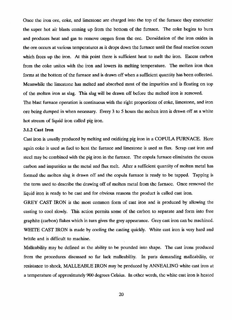
Once the iron ore, coke, and limestone are charged into the top of the furnace they encounter
the super hot air blasts coming up from the bottom of the furnace. The coke begins to burn
and produces heat and gas to remove oxygen from the ore. Deoxidation of the iron oxides in
the ore occurs at various temperatures as it drops down the furnace until the final reaction occurs
which frees up the iron. At this point there is sufficient heat to melt the iron. Excess carbon
from the coke unites with the iron and lowers its melting temperature. The molten iron then
forms at the bottom of the furnace and is drawn off when a sufficient quantity has been collected.
Meanwhile the limestone has melted and absorbed most of the impurities and is floating on top
of the molten iron as slag. This slag will be drawn off before the melted iron is removed.
The blast furnace operation is continuous with the right proportions of coke, limestone, and iron
ore being dumped in when necessary. Every 3 to 5 hours the molten iron is drawn off as a white
hot stream of liquid iron called pig iron.
3.1.2 Cast Iron
Cast iron is usually produced by melting and oxidizing pig iron in a C O P U L A F U R N A C E . Here
again coke is used as fuel to heat the furnace and limestone is used as flux. Scrap cast iron and
steel may be combined with the pig iron in the furnace. The copula furnace eliminates the excess
carbon and impurities as the metal and flux melt. After a sufficient quantity of molten metal has
formed the molten slag is drawn off and the copula furnace is ready to be tapped. Tapping is
the term used to describe the drawing off of molten metal from the furnace. Once removed the
liquid iron is ready to be cast and for obvious reasons the product is called cast iron.
G R E Y CAST IRON is the most common form of cast iron and is produced by allowing the
casting to cool slowly. This action permits some of the carbon to separate and form into free
graphite (carbon) flakes which in turn gives the grey appearance. Grey cast iron can be machined.
WHITE CAST IRON is made by cooling the casting quickly. White cast iron is very hard and
brittle and is difficult to machine.
Malleability may be defined as the ability to be pounded into shape. The cast irons produced
from the procedures discussed so far lack malleability. In parts demanding malleability, or
resistance to shock, M A L L E A B L E IRON may be produced by A N N E A L I N G white cast iron at
a temperature of approximately 900 degrees Celsius. In other words, the white cast iron is heated
20
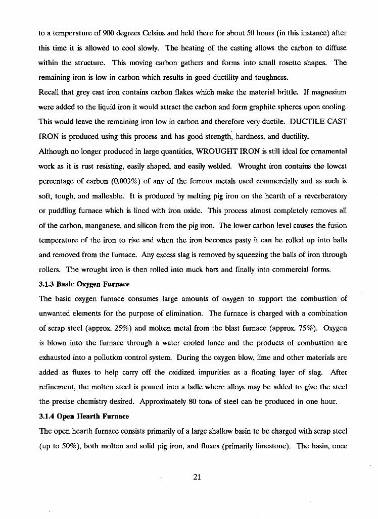
to a temperature of 900 degrees Celsius and held there for about 50 hours (in this instance) after
this time it is allowed to cool slowly. The heating of the casting allows the carbon to diffuse
within the structure. This moving carbon gathers and forms into small rosette shapes. The
remaining iron is low in carbon which results in good ductility and toughness.
Recall that grey cast iron contains carbon flakes which make the material brittle. If magnesium
were added to the liquid iron it would attract the carbon and form graphite spheres upon cooling.
This would leave the remaining iron low in carbon and therefore very ductile. DUCTILE CAST
IRON is produced using this process and has good strength, hardness, and ductility.
Although no longer produced in large quantities, W R O U G H T IRON is still ideal for ornamental
work as it is rust resisting, easily shaped, and easily welded. Wrought iron contains the lowest
percentage of carbon (0.003%) of any of the ferrous metals used commercially and as such is
soft, tough, and malleable. It is produced by melting pig iron on the hearth of a reverberatory
or puddling furnace which is lined with iron oxide. This process almost completely removes all
of the carbon, manganese, and silicon from the pig iron. The lower carbon level causes the fusion
temperature of the iron to rise and when the iron becomes pasty it can be rolled up into balls
and removed from the furnace. Any excess slag is removed by squeezing the balls of iron through
rollers. The wrought iron is then rolled into muck bars and finally into commercial forms.
3.1.3 Basic Oxygen Furnace
The basic oxygen furnace consumes large amounts of oxygen to support the combustion of
unwanted elements for the purpose of elimination. The furnace is charged with a combination
of scrap steel (approx. 25%) and molten metal from the blast furnace (approx. 75%). Oxygen
is blown into the furnace through a water cooled lance and the products of combustion are
exhausted into a pollution control system. During the oxygen blow, lime and other materials are
added as fluxes to help carry off the oxidized impurities as a floating layer of slag. After
refinement, the molten steel is poured into a ladle where alloys may be added to give the steel
the precise chemistry desired. Approximately 80 tons of steel can be produced in one hour.
3.1.4 Open Hearth Furnace
The open hearth furnace consists primarily of a large shallow basin to be charged with scrap steel
(up to 50%), both molten and solid pig iron, and fluxes (primarily limestone). The basin, once
21
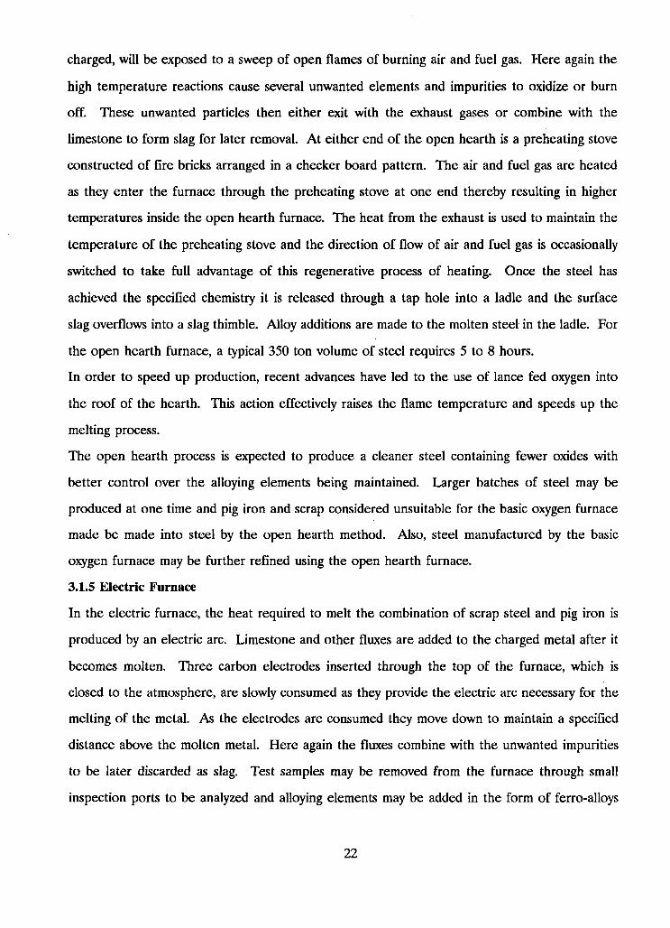
charged, will be exposed to a sweep of open flames of burning air and fuel gas. Here again the
high temperature reactions cause several unwanted elements and impurities to oxidize or burn
off. These unwanted particles then either exit with the exhaust gases or combine with the
limestone to form slag for later removal. At either end of the open hearth is a preheating stove
constructed of fire bricks arranged in a checker board pattern. The air and fuel gas are heated
as they enter the furnace through the preheating stove at one end thereby resulting in higher
temperatures inside the open hearth furnace. The heat from the exhaust is used to maintain the
temperature of the preheating stove and the direction of flow of air and fuel gas is occasionally
switched to take full advantage of this regenerative process of heating. Once the steel has
achieved the specified chemistry it is released through a tap hole into a ladle and the surface
slag overflows into a slag thimble. Alloy additions are made to the molten steel in the ladle. For
the open hearth furnace, a typical 350 ton volume of steel requires 5 to 8 hours.
In order to speed up production, recent advances have led to the use of lance fed oxygen into
the roof of the hearth. This action effectively raises the flame temperature and speeds up the
melting process.
The open hearth process is expected to produce a cleaner steel containing fewer oxides with
better control over the alloying elements being maintained. Larger batches of steel may be
produced at one time and pig iron and scrap considered unsuitable for the basic oxygen furnace
made be made into steel by the open hearth method. Also, steel manufactured by the basic
oxygen furnace may be further refined using the open hearth furnace.
3.1.5 Electric Furnace
In the electric furnace, the heat required to melt the combination of scrap steel and pig iron is
produced by an electric arc. Limestone and other fluxes are added to the charged metal after it
becomes molten. Three carbon electrodes inserted through the top of the furnace, which is
closed to the atmosphere, are slowly consumed as they provide the electric arc necessary for the
melting of the metal. As the electrodes are consumed they move down to maintain a specified
distance above the molten metal. Here again the fluxes combine with the unwanted impurities
to be later discarded as slag. Test samples may be removed from the furnace through small
inspection ports to be analyzed and alloying elements may be added in the form of ferro-alloys
22
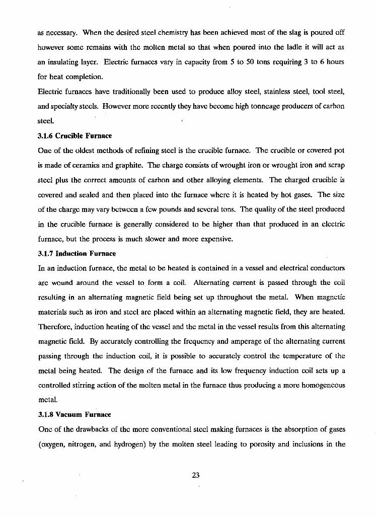
as necessary. When the desired steel chemistry has been achieved most of the slag is poured off
however some remains with the molten metal so that when poured into the ladle it will act as
an insulating layer. Electric furnaces vary in capacity from 5 to 50 tons requiring 3 to 6 hours
for heat completion.
Electric furnaces have traditionally been used to produce alloy steel, stainless steel, tool steel,
and specialty steels. However more recently they have become high tonneage producers of carbon
steel.
3.1.6 Crucible Furnace
One of the oldest methods of refining steel is the crucible furnace. The crucible or covered pot
is made of ceramics and graphite. The charge consists of wrought iron or wrought iron and scrap
steel plus the correct amounts of carbon and other alloying elements. The charged crucible is
covered and sealed and then placed into the furnace where it is heated by hot gases. The size
of the charge may vary between a few pounds and several tons. The quality of the steel produced
in the crucible furnace is generally considered to be higher than that produced in an electric
furnace, but the process is much slower and more expensive.
3.1.7 Induction Furnace
In an induction furnace, the metal to be heated is contained in a vessel and electrical conductors
are wound around the vessel to form a coil. Alternating current is passed through the coil
resulting in an alternating magnetic field being set up throughout the metal. When magnetic
materials such as iron and steel are placed within an alternating magnetic field, they are heated.
Therefore, induction heating of the vessel and the metal in the vessel results from this alternating
magnetic field. By accurately controlling the frequency and amperage of the alternating current
passing through the induction coil, it is possible to accurately control the temperature of the
metal being heated. The design of the furnace and its low frequency induction coil sets up a
controlled stirring action of the molten metal in the furnace thus producing a more homogeneous
metal.
3.1.8 Vacuum Furnace
One of the drawbacks of the more conventional steel making furnaces is the absorption of gases
(oxygen, nitrogen, and hydrogen) by the molten steel leading to porosity and inclusions in the
23
metal when it solidifies. With the melting of steel in a vacuum furnace most of the gases are
removed with the vacuum pumps leaving only a small amount of gases present in the furnace.
The absence of these gases improves many of the qualities of the steel including ductility, magnetic
properties, impact strength, and fatigue strength. These qualities would be otherwise unattain
able. Two main types of vacuum furnaces used today are the @1 [3.1.08.1 Vacuum Arc Furnace]
and the @1 [3.1.08.2 Vacuum Induction-Type Furnace].
Although the resulting steel is not quite as pure, vacuum degassers are an alternative to the
vacuum furnace and involve subjecting the molten steel from a more conventional steel making
furnace to a vacuum. Two types of vacuum degassing systems are @1 [3.1.08.3 Vacuum Stream
dagassing] and @1[3.1.08.4 Ladle Degassing].
3.1.8.1 Vacuum Arc Furnace
The metal charge for this furnace comes from huge consumable electrodes that were formed
from the steel product of a more conventional steel making furnace. These long cylindrical metal
electrodes are fed into the vacuum arc furnace at a controlled rate of speed to control the arc
length. As the metal melts and drops from the end of the electrode, air and contaminating gases
are constantly being pumped out of the furnace by vacuum pumps. The molten metal falls into
a water-cooled steel crucible below which is the grounded part of the electrical circuit. This
process is frequently used when the uniformity and purity of the metal is very important. No
provision is made in this furnace for the adding of alloying elements.
3.1.8.2 Vacuum Induction-Type Furnace
The vacuum induction process involves charging an electric vacuum induction furnace with scrap
or molten steel after most of the atmosphere has been evacuated. The induction furnace is
airtight and attached to vacuum pumps so that most of the contaminating gases may be constantly
removed. Provisions are made to allow alloying materials to be added to the furnace without
destroying the vacuum. The heating of the metal, the pouring of the metal into ingots, and the
cooling of the ingots are all done under vacuum conditions to prevent any contamination. The
vacuum induction furnace is used when close control of the chemistry of the metal is of prime
importance.
24
3.1.83 Vacuum Stream Degassing
Vacuum stream degassing utilizes a ladle of molten steel from a conventional furnace. The molten
steel is separated into droplets before being exposed to the vacuum in the degassing chamber.
Most of the undesirable gases are drawn away from the droplets before they fall and solidify into
an ingot mold below which is also in the vacuum chamber.
3.1.8.4 Ladle degassing
Ladle degassing also utilizes a ladle of molten steel from a conventional furnace. A vacuum
vessel is placed over the ladle with a funnel like end placed into the molten metal. With the
vacuum pumps engaged, atmospheric pressure forces molten steel up into the vacuum chamber
where unwanted gasses may be removed. After a sufficient period of time, the vacuum chamber
is raised so that gravity will force the cleansed molten steel back into the ladle. This process
must be performed several times to ensure all of the steel in the ladle gets degassed.
3.1.9 First Solid Forms of Steel
Molten steel from the basic steel making furnaces follow one of two major routes to the rolling
mills where most of the industries finished products are formed.
1. INGOTS
The ingot molds are filled with the molten steel which then begins to cool and solidify immediately
from the outside inwards. When the steel has solidified enough for the ingots to be removed
from their molds they are taken to a furnace called a soaking pit. The ingots remain there soaking
in heat until they reach uniform temperature throughout. The reheated ingots are then taken
from the soaking pit to the roughing mill where they are shaped into semi-finished steel (usually
blooms, billets, or slabs). Some roughing mills are the first in a series of continuous mills, feeding
sequences of finishing rolls.
2. CAST SLABS (Strand Casting)
A continuous casting process is utilized to turn the liquid steel into semi-finished steel products.
The liquid steel is poured from the ladle into a reservoir or TUNDISH where it is then permitted
to flow vertically into a water cooled copper mold. The liquid metal in contact with the cool
mold solidifies quickly and shrinks away from the side of the mold. A shell has now formed
around the molten metal in the center of the mold. Further down the line the column of steel
25
is supported by a system of withdrawing rolls. Meanwhile, a system of cooling water jets spray
the steel as it emerges from the mold until solidification is complete. The continuous casting
process generally produces steel in the form of blooms, billets, or slabs. BLOOMS are large and
mostly square in cross section and are used in the manufacture of beams and columns. BILLETS
are smaller and generally square in cross section and are used in the production of bars, pipes,
wire, and wire products. SLABS tend to be wider in cross section and are used to make sheets,
strips, plates, and other flat rolled sheet products.
3.1.10 Processing Metals
Molten metal from the furnace is originally cast into ingots or molds for later processing. In
preparation for final processing, these castings are reheated to a definite temperature depending
on the metal. The metal is then formed into a finished or semi-finished product by one of the
following methods: 1. Casting, 2. Rolling (hot or cold), 3. Forging, 4. Extruding, or 5. Drawing.
CASTING is a common method used to produce objects with intricate shapes. The metal is cast
into a mold that may be stationary or spinning (centrifugal).
R O L L I N G is used to form the molded rough stock into more usable shapes while improving the
physical properties of the metal. Large powerful rollers in a rolling mill are used to produce
rails, T beams, I beams, angles, bar stock, etc. Numerous operations may be required to form
some of the more complicated shapes.
FORGING may be either drop or press and is used to obtain shapes stronger than castings.
Generally these are shapes which are not easily rolled. Forge hammers and/or forming dies are
used to pound the metal into the desired shape.
E X T R U D I N G metal is a process by which metal normally in its plastic state is pushed with great
force through dies which are cut in the shape of the desired cross section.
D R A W I N G is a process of pulling metal through dies to form wires, tubing, and moldings.
In addition to the above methods, many intricate shapes are now being produced by the POW
D E R E D M E T A L S PROCESS. The metal to be used is reduced to a powdered texture and is
forced under pressure into a heated steel mold. The properties of the finished part approximate
those of the original solid metal. Most of these parts may be used without any additional
machining or grinding as they are produced to very close tolerances.
26
Metal may also be reduced to actual fibers. The fibers are then laid down or woven to form
mats. Mats of fibrous metal are finding increasing use in resistance welding where the mats are
placed between parts to be welded.
3.2 The Micro-Structure of Iron and Steel
Iron and steel possess a crystalline structure when in the solid state. This simply means that they
possess a regular geometric arrangement of atoms. The symmetry of crystalline structures may
be explained in terms of the unit cell. The unit cell is a common arrangement of atoms which
when repeated successively in three dimensions will form the crystal structure. The most common
unit cell for most metals is cubic and may be either body-centered or face centered. The
Body-Centered Cube is constructed with one atom at each corner and one located at the center
of the cube. The Face-Centered Cube contains an atom at each corner and one at the center
of each face. Iron is unique among the common structural metals because it changes from a
face-centered cubic to a body-centered cubic during slow cooling.
If more than one element is present, the unit cells may change slightly or considerably depending
on the identity of the atoms present. The crystal lattice, or atomic pattern, will have to
accommodate the new atoms either substitutional^ or interstitially. In a substitutional solid
solution the atoms of the additional element have simply replaced the atoms of the parent metal
in the crystal lattice. If the atoms of the additional element are quite small, however, they will
tend to locate themselves at in-between points, or interstices, in the lattice. This latter
arrangement is referred to as an interstitial solid solution. Nickel will form a substitutional solid
solution in iron while elements such as carbon, hydrogen, and nitrogen form interstitial solid
solutions in iron. Interstitial solutions are usually limited to small but important values of solu
bility.
3.2.1 Formation of the Solid Phase
The initial solidification from liquid form will occur at cooler regions of the liquid (container
walls) and at locations where accidental groupings of atoms favour solidification. The first tiny
crystals to form are called nuclei and they act as seeds for crystal growth. In a cubic lattice the
growth proceeds preferentially in directions perpendicular to the cube faces. This type of growth
leads to the formation of tree like skeletons (called dendrites) with branches and subbranches at
27
right angles to each other. Each growth forms what is termed a dendritic crystal, or grain. These
dendritic crystals develop independently and randomly and as such exhibit independent and
random orientation. Therefore grain boundaries ensue as the individual crystals grow into mutual
contact. The completely solid metal then is composed of individual crystals, or grains, held
together by atomic attractive forces at the interface boundaries.
To put things into perspective, a piece of metal the size of a sugar cube may contain thousands
of these grains. In addition, the size of the grains may have a considerable influence on the
steel's physical properties and behavior during heat treatment.
Ingot Grain Growth and Weld Metal Grain Growth clearly show expected grain orientation. The
growth of nuclei into large crystals will tend to follow a direction opposite to the temperature
gradient. In the ingot, the nuclei form first on the vessel walls and then grow inward with little
opportunity to spread sideways because of adjacent crystals. The surface of the weld metal is
analogous to the vessel wall. In both cases, the crystals form as elongated grains, perpendicular
to the walls or weld surface resulting in a columnar structure. A crystal structure of this nature
may result in planes of weakness parallel to the grain growth which may tear or crack during
cooling or during subsequent forming operations.
3.2.2 Iron, Carbon, and Steel
Commercially pure iron is moderately weak and plastic and is not suitable for use as a construction
material where strength is required. However, the addition of less than 1% carbon turns the
iron into one of the most valuable engineering materials in existence today, steel. Carbon steel
is the combination of iron and controlled amounts of carbon. In addition, New and desirable
properties may be achieved if carbon steel is then combined with controlled amounts of other
metals such as chromium, manganese, molybdenum, nickel, tungsten, vanadium, etc.. These are
referred to as Alloy Steels.
Table_l shows the percent of carbon present in the iron and steel classes.
28
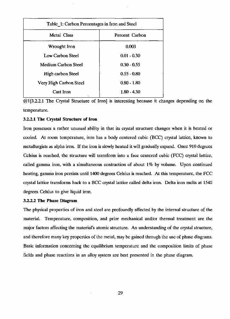
Table_l: Carbon Percentages in Iron and Steel
Metal Class Percent Carbon
Wrought Iron 0.003
Low Carbon Steel 0.01 - 0.30
Medium Carbon Steel 0.30 - 0.55
High carbon Steel 0.55 - 0.80
Very High Carbon Steel 0.80 -1.80
Cast Iron 1.80 - 4.30
@1[3.2.2.1 The Crystal Structure of Iron] is interesting because it changes depending on the
temperature.
3.2.2.1 The Crystal Structure of Iron
Iron possesses a rather unusual ability in that its crystal structure changes when it is heated or
cooled. At room temperature, iron has a body centered cubic (BCC) crystal lattice, known to
metallurgists as alpha iron. If the iron is slowly heated it will gradually expand. Once 910 degrees
Celsius is reached, the structure will transform into a face centered cubic (FCC) crystal lattice,
called gamma iron, with a simultaneous contraction of about 1% by volume. Upon continued
heating, gamma iron persists until 1400 degrees Celsius is reached. At this temperature, the FCC
crystal lattice transforms back to a BCC crystal lattice called delta iron. Delta iron melts at 1540
degrees Celsius to give liquid iron.
3.2.2.2 The Phase Diagram
The physical properties of iron and steel are profoundly affected by the internal structure of the
material. Temperature, composition, and prior mechanical and/or thermal treatment are the
major factors affecting the material's atomic structure. An understanding of the crystal structure,
and therefore many key properties of the metal, may be gained through the use of phase diagrams.
Basic information concerning the equilibrium temperature and the composition limits of phase
fields and phase reactions in an alloy system are best presented in the phase diagram.
29
It may be recalled that a pure metal always freezes at a single temperature whereas most alloys
freeze over a range of temperatures. Most of the information on the phase diagram must be
determined experimentally, the freezing and melting temperatures being one of the easier tasks.
The simplistic Copper and Nickel Phase Diagram, @l[metall.pcx], indicates how the diagram
would look for solid solution, binary alloys. A solid solution alloy will show only one type of
crystal structure in the solid state no matter what the mixing proportion. The three phases (liquid,
liquid plus solid, and solid) are separated by the liquidus and solidus lines. The liquidus line
indicates where freezing begins and the solidus line indicates where freezing is complete. Note
that if the changes in the alloy are reversible, as they are with most phase diagrams, then equi
librium conditions are being maintained. As a result, phase diagrams are commonly called
equilibrium diagrams.
The Copper-Silver Phase Diagram, @l[metal2.pcx], is indicative of an alloy in which the com
ponent metals have partial or limited solid solubility. In this case, the metals, when combined in
certain proportions, will form alloys in which there are two separate phases in the solid state. As
can be seen on the copper-silver phase diagram, there exists one alloy that freezes at a single
temperature which is lower than all the other alloys in the series. Although for many of the
other alloys freezing is complete at this temperature, it begins at a considerably higher temper
ature. The lowest melting alloy in the series is called a eutectic, and a diagram containing such
an alloy is called a eutectic diagram. A look at the copper-silver phase diagram shows that the
eutectic type of structure will only form in the alloys containing between 9 and 92 percent copper.
Alloys with less than 9% copper will solidify as single phase alloys containing crystals of a solid
solution of copper in silver, called alpha phase. Alloys with more than 92% copper also contain
a single phase, a solid solution of silver in copper, called beta phase. It may be observed that
alloys with compositions permitting passage through the alpha or beta phase will freeze in a
manner analogous to a solid solution system.
The Silver Rich Portion of the Copper-Silver Phase Diagram, @ lfmetal3.pcx] may be used to
indicate the changes in a eutectic alloy during cooling. Point A l of the liquidus line on the
diagram indicates where the 15% copper alloy would begin forming its primary crystals. The
exact composition of those crystals is indicated by point B l on the solidus line. As cooling
30
continues, the composition of each new crystal is determined by the solidus line with the liquid
composition determined by the liquidus line. A look a points A2 and B2 indicates how the
progression is moving through the liquid plus solid phase. By the time the cooling has proceeded
to the eutectic freezing temperature, the crystals will have the composition shown by point B3
with the liquid now at the eutectic alloy composition. The remainder of the freezing must now
take place through simultaneous solidification of alpha and beta solid solutions. This simultaneous
freezing will form a structure composed of either thin alternating plates of the two phases or a
"salt and pepper" type of intermingling. The final solid alloy of 15% copper will contain the
larger primary crystals of alpha formed first at higher temperatures, together with a eutectic
mixture of the alpha and beta.
Although other alloys may involve more complicated arrangements between the components,
almost all phase diagrams may be broken up into the two basic types described above.
3.2.23 The Iron-Carbon Phase Diagram
The Iron-Carbon Equilibrium Diagram, @1 [metal4.pcx], is important for producing, forming,
welding, and heat treating steel and cast iron. From this diagram, the phases forming in alloys
of iron and carbon may be determined through known values of carbon content and sustained
temperature. Note that the diagram is cut off at approximately 5% carbon because the rest is
of little interest. Weldable steels typically have carbon contents less than 0.5%.
Starting with the molten alloy (with composition between 0 and 4.3 percent carbon), the first
phase encountered upon cooling is the liquid plus austenite region. The complicated region
involving delta iron may be ignored. Austenite is a solid solution of gamma iron containing up
to 2.11% dissolved carbon. Like pure gamma iron, austenite too possesses the face centered
cubic crystal structure. Austenite is soft and ductile and is a very important region of the diagram
when heat treating steel. If the molten alloy contained between 4.3 and 6.67 percent carbon
then the first phase encountered would be the cementite plus liquid phase, only a portion of
which is shown on the diagram. Cementite is also known as iron carbide and its molecular formula
is Fe3C. Cementite is hard and brittle and is present in all steel and cast iron at room temperature.
Although it is not well shown in the diagram, austenite forms a eutectic with cementite. The
31
pure eutectic alloy contains 4.3 % carbon and melts at 1130 degrees Celsius, the lowest melting
point of any alloy in the system. Note that any phase changes taking place below the eutectic
temperature (1130 degrees Celsius) will necessarily involve changes in solid metal.
Consider now the portion of the diagram representing the iron/carbon alloys which fall under the
classification of steels. Recall that plain carbon steels contain between 0.01 and 1.80 percent
carbon. It can be seen that the lines below the austenite region resemble those of a eutectic
system. However, because only solid phases are present, the area is designated eutectoid. In
other words, a solid solution of carbon in alpha iron, or ferrite, forms a eutectoid with iron
carbide, or cementite. The pure eutectoid alloy, called pearlite, contains 0.77% carbon and melts
at 727 degrees Celsius.
The transformation of steels with less than 0.77 % carbon results in primary or proeutectoid
ferrite (ferrite formed above the eutectoid temperature) and pearlite (eutectoid). 0.77 % carbon
steels transform wholly to pearlite. Steels with greater than 0.77 % carbon form proeutectoid
cementite and pearlite. The relative amounts of proeutectoid and eutectoid crystals that form
from the austenite depend on the carbon content of the steel.
The manner in which proeutectoid crystals of ferrite or cementite separate from the austenite is
illustrated in @1 [metal9.pcx]. Part a.) of the figure shows austenite of a 0.4 % carbon steel
possessing a granular structure. As the steel cools below the upper transformation temperature,
ferrite will precipitate at the grain boundaries of the austenite and gradually increase in volume.
Refer to part b.) of the figure. The ferrite will have completely surrounded islands of austenite
by the time the lower transformation temperature has been reached, part c.) of the figure. Now,
at this temperature and at the eutectoid level of carbon content, the remaining austenite will
transform to pearlite resulting in the final structure shown in part d.) of the figure. Of course,
all of the above phase changes require equilibrium cooling conditions.
Relatively slow - equilibrium cooling conditions:
Under equilibrium cooling conditions in the composite range of interest (less than 0.8 % Carbon),
austenite transforms to ferrite and pearlite. Ferrite possesses gamma iron's body centered cubic
structure and will dissolve up to 0.025 percent carbon. It is soft, ductile, and present in all steel
and cast iron. Pearlite is composed of alternating platelet layers of ferrite and cementite. Pearlite
32
possesses properties in between those of ferrite and cementite. In carbon steels under equilibrium
conditions; austenite, ferrite, and cementite are the only three phases that may be present in the
solid state.
The conversion from austenite to pearlite is relatively slow because the crystal structure has to
change (fcc/bcc) and the surplus carbon needs time to diffuse to the cementite plates.
Relatively fast - nonequilibrium cooling conditions:
If insufficient time is allowed for the austenite/pearlite transformation then, depending on the
chemical composition and cooling rate, other structures such as fine-pearlite, martensite, or
bainite may be formed. The prevention of normal transformations in the steel is essential to
developing its ability to harden.
Fine pearlite is a much harder phase than the regular slow cooling pearlite. In addition, the
plate widths are significantly smaller.
If the cooling rate is greatly accelerated then the transformation from austenite to pearlite will
be suppressed. The surplus carbon simply cannot diffuse out in time. Instead, it becomes trapped
in a supersaturated solution which takes up a body-centered-tetragonal structure, martensite. The
martensite phase is hard, brittle, and highly stressed internally. Martensite formation begins at
the "Ms" temperature which is usually around 350 degrees Celsius. The "MP temperature marks
the end of the austenite to martensite transformation, below which no further transformation of
austenite takes place.
The "critical cooling velocity" defines the cooling rate necessary to suppress the austenite/pearlite
transformation. This critical rate is reduced with the presence of alloying elements.
Bainite is formed if the critical cooling rate or better is utilized down to the "Ms" temperature
but below that the material is no longer quenched. The properties of bainite are in between
those of martensite and pearlite.
@1 [metal5.pcx] summarizes the crystal structure transformations.
3.23 Time-Temperature-Transformation (TTT) Curves
It should be clear by now that final phase formation depends primarily on time and temperature.
The time required for transformation to the various phases at constant temperature has been
studied experimentally for quite some time. One of the more useful outcomes of this research
33
has been the development of the isothermal transformation diagram. These diagrams display
time-temperature-transformation curves that may be used to predetermine likely transformations.
@1 [metal6.pcx] illustrates the curves. The following conclusions can be drawn regarding the
curves:
1. The nose of the curve defines the shortest time for austenite transformation. Rapid cooling
rates will bypass the nose, resulting in a lower temperature transformation. This action generally
leads to a harder final phase.
2. The final structure, of course, depends on the transformation temperature.
3. Carbon and alloy contents influence the shape of the curve as well as its position on the time
axis. Carbon, manganese, and nickel will shift the curve bodily to the right without significantly
changing its shape. On the other hand, chromium and molybdenum will alter the shape by forcing
the austenite/pearlite transformation farther to the right than the austenite/bainite transformation.
4. If it were possible to displace the curve bodily to the right than the martensite phase would
form even during slow cooling.
5. The temperature required for the complete conversion to martensite (Mf) might be below
ambient temperature.
One point to be noted about isothermal diagrams is that they cannot be used directly to obtain
quantitative information about phase changes in continuous cooling; nor can the data be con
sidered exact when applied to a different heat of the same grade of steel. The diagrams are,
however, beneficial in showing the products of austenite decomposition at different temperature
levels and the effects of various factors on them. In addition, they give a clue to the response
of a steel to the cooling rates following welding.
3.2.4 Continuous Cooling Transformation (CCT) Diagrams
The constant temperature representation of the T I T curves is somewhat unrepresentative of
welding where rapid continuous cooling takes place. More relevant information may be obtained
from a CCT diagram, @1 [metal7.pcx], in which phase changes are tracked for a variety of cooling
rates. Production of these diagrams for weld heating and cooling requires considerable exper-
34
imental effort. For construction of the diagram shown, special apparatus was used to simulate
H A Z cooling, and the transformation points were derived from both dimensional and temperature
changes in the specimen. There exists few diagrams of this type.
3.2.5 HAZ Microstructures in Steel Welds
Grain growth will thrive when a steel is held at the upper austenite range for a significant length
of time. This growth proceeds through grain boundary migration and coalescence. In general,
coarse grained steels possess poor fracture toughness. During welding coarse grain zones are
produced, the size of which depends on the welding process and parameters. Notch toughness
may be improved by using normalizing procedures to reduce the grain size. This procedure
involves uniformly heating the complete fabrication to a point just above the T l temperature,
see @l[metal8.pcx], and then allowing it to cool naturally in air. At this time, the practical
difference between normalizing and stress-relieving will be noted. The required furnace tem
perature for stress-relieving is much higher than that for normalizing, 950 as compared to 650
degrees Celsius, respectively. At this higher temperature, the structure may not possess the
strength required to support its own weight.
For material heated in the lower austenite range, T l to T2 in @l[metall8.pcx], a much finer
grained microstructure will be produced. The upper temperature limit T2 is controlled largely by
grain refining agents such as aluminum, niobium, vanadium, and nitrogen. These elements form
carbides and nitrides which prevent grain boundary migration. Unfortunately, as the temperature
is increased they lose their effectiveness because they go into solution.
The remaining portion of the H A Z , seen in the figure between the TO and T l temperatures,
permits pearlite from the original parent metal to transform to austenite. It is possible to form
martensite in this region if the material is high in carbon and other alloying elements, and if
subsequent cooling is rapid enough.
The bottom of the figure shows the microstructure which varies continuously across the H A Z .
Unaffected parent metal merges into fine and then coarse grain phases to the fusion line which
defines the boundaries of the cast weld structure.
35
In multipass welds, each weld bead is partially reheated and tempered by subsequent passes. This
treatment greatly improves toughness, as carbon diffuses out of any martensite previously formed,
leading to a tough microstructure consisting of ferrite and spheroidised carbides. It becomes
clear now that the welding engineer must make a choice between multipass welds which give
excellent metallurgical properties and single pass welds which give inferior properties but are
more economical.
33 Welding Metallurgy in Structural Steels
Modern structural steels are comprised mainly of Carbon-manganese (C-Mn) or low alloy steels.
C-Mn steels with up to 0.5 percent carbon and 1.7 percent manganese are extensively used to
build structures and machinery. These steels will additionally contain up to 0.6% Silicon and
occasionally a small amount of aluminum for grain size refinement. Although chrome, nickel,
molybdenum, copper and columbium can be present as residual elements, no other deliberate
alloying elements are added.
Low alloy steels incorporate deliberate additions of one or more elements to modify their strength
and/or toughness. These steels contain less than 5 percent by weight of total alloying additions,
excluding manganese and silicon. The alloying additions are generally comprised of chromium,
nickel, molybdenum, and vanadium. Microalloyed steels are relatively new and contain less than
1 percent by weight of alloying elements, again excluding manganese and silicon. The alloy
additions here are some combination of molybdenum, columbium, vanadium and aluminum.
The microstructure of a simple C-Mn steel, cooled slowly from high temperatures can be described
with the Iron-Carbon equilibrium diagram, @1 [metal4.pcx]. Consider a typical medium carbon
steel which has a composition less than the eutectoid composition (0.77 %). Under slow cooling,
where the diffusion of carbon is relatively uninhibited, certain portions of austenite (stable at
high temperature) will decompose into ferrite (which has a very low solubility for carbon,) while
remaining portions become carbon enriched. The carbon level in this remaining austenite will
approach the eutectoid composition, through continued slow cooling, where it will then be
transformed into pearlite below 723 degrees Celsius. @1 [metal9.pcx] illustrates the structural
changes from austenite at 870 degrees Celsius to pearlite and ferrite at room temperature. If
the cooling rate is increased, there is less time for diffusion to occur and the result is a finer
36
pearlite with improved strength and toughness. Since the transformation starts at austenite grain
boundaries, a finer austenite grain size will also improve strength and toughness, primarily by
providing a better relative distribution of the pearlite.
Still further increases in cooling rate will minimize the time for carbon diffusion and subsequently
lower the nucleation temperature. Once the nucleation temperature drops below 550 degrees
Celsius, bainite will form at the nucleation sites. Bainite may be further classified into upper and
lower bainite with the latter forming at lower nucleation temperatures. Lower bainite contains
very fine carbide particles in a matrix of ferrite with more carbon than the equilibrium limit. This
residual carbon distorts the body centered cubic ferrite structure, which has less room for
interstitial atoms than the more open faced austenite cubic. At very high cooling rates, carbon
diffusion is nearly totally suppressed, the transformation temperature drops below 250 degrees
C, and a shear transformation to martensite occurs. In this structure, the austenite must transform
to a ferritic structure, but still retain the carbon in solution. The interstitial carbon greatly distorts
the lattice, producing a hard, brittle material. The hardness ( and brittleness) rise directly with
the carbon level in the steel, so that higher carbon levels produce more distortion, higher hardness
and lower toughness.
The carbon content is the key ingredient for determining the maximum achievable hardness
associated with a severe quench (rapid cooling rate). Whether or not the steel achieves that
maximum hardness depends on the cooling rate and the alloy content. Most alloying elements
tend to diminish the rate of carbon diffusion thereby promoting lower temperature transformation
products and increased hardenability. Therefore maximum hardness in a section should be rel
atively easy to achieve. The Jominy end-quench hardness test is often used to assess this behavior.
A jet of cold water is sprayed on the end of a hot bar of steel, and the hardness measured along
the length. Maximum hardness, based on carbon content, is achieved on the end of the bar
adjacent to the cooling water where the quenching effect is most severe. The steel further along
the bar experiences a slower cooling rate and therefore increased carbon diffusion. This results
in a softer microstructure. The addition of certain alloying elements can delay this behavior and
increase the hardenability through an extension of maximum hardness along the length of the
bar. A correlation of Jominy data with an Isothermal Transformation diagram will show which
37
transformation products will occur for a steel cooled rapidly from about 900 degrees C to a
specified lower temperature, which is then held until a transformation occurs. Unfortunately, it
does not happen this way in practise, especially in welding, where cooling takes place starting
from close to the melting point and where cooling is continuous, not isothermal. Instead, in
these conditions, continuous cooling transformation diagrams may used to determine transfor
mation behavior, @l[metall2.pcx].
If we can determine the transformation behavior, then welding problems can be approached with
a higher degree of confidence. Two important regions of the problem are the weld metal and
the H A Z . Solidification cracking is one common problem associated with the weld metal. It
occurs because low-melting point constituents, primarily associated with sulphur, segregate. With
high restraint comes an increase in strain as the metal solidifies. The last material to freeze may
be called upon to fill a larger void than its volume permits, the result, of course, is a hot crack.
High welding speeds and small weld beads tend to produce tear drop shaped welds, see part a.)
of @l[metall3.pcx]. This shape tends to concentrate segregates at the centerline and promote
cracking. A superior pool shape is illustrated in part b.) of the same figure. It tends to direct
segregates in to the molten weld pool (at the ends of the dendrites) thus delaying or preventing
centerline cracks. Manganese may be used to tie up sulphur in a sulphide with less inclination
to cause cracking than iron sulphides. Because sulphur segregation is increased by higher carbon
levels, the Manganese to Sulphur ratio must also increase, @l[metall4.pcx]. Centerline cracking
is a larger concern with deep penetration narrow welds, see @l[metall5]. Multipass welding
may be used to control this problem.
The principal affliction in the heat affected zone (HAZ) is cold cracking. @1 [metall6.pcx]
illustrates its many forms. Although the weld metal is also susceptible, it is to a lesser extent.
The simultaneous occurrence of four events is necessary to cause cold cracking:
1) Tensile stresses.
2) Low temperature (below 200 degrees C)
3) Hydrogen levels above 5-10ml/100gm metal.
4) A hardened (martensitic or bainitic) microstructure susceptible to hydrogen
cracking.
38
We essentially have no control over the first two events and so we will confine our attention to
the latter criteria. It appears that diffusible hydrogen atoms induce cracking by generating low
stress fractures in distorted ferrite structures by acting as interstitial atoms on particular crystal
planes. Of course, the best way to control this cracking is to avoid the existence of hydrogen in
susceptible areas. @l[metall7] illustrates that this is possible with the use of clean, dry con
sumables in some arc welding processes, but not all. Foresight is necessary in the selection of
welding consumables and processes so that hydrogen levels may be controlled. Selecting low
hydrogen electrodes and ensuring they are known to be clean and dry before use is a necessary
precaution in susceptible areas. The use of preheat to minimize moisture levels and promote
hydrogen diffusion out of the weld zone is another suitable, and often necessary precaution.
If low hydrogen procedures are not thought to be completely reliable or if the material is highly
susceptible, then manipulation of microstructure and hardness may be required to control
hydrogen cracking. Three types of control exist, Figure 11. In general, for carbon contents less
than 0.11%, only minimal precautions are necessary. This is because the lattice distortion and
hardness are relatively low even when alloy levels (and hardenability) are very high. These steels
are located in Zone I of @l[metall8]. Hardenability is described by the carbon equivalent
formula on the X axis. This is because the carbon equivalent formula empirically relates the
alloy level to an equivalent amount of carbon which would give an identical hardenability and
maximum hardness is determined by actual carbon levels. Low hardenability steels in Zone II
may be hardness controlled by welding procedure variables such as preheat temperature and heat
input (voltage times current divided by welding speed). The preheat and heat input are estab
lished such that the cooling rate in the H A Z results in a maximum hardness that is representative
of a microstructure which is not susceptible to hydrogen cracking. Often a maximum hardness
of 350Hv is taken. Although hardnesses of up to 450Hv are acceptable, provided hydrogen levels
can be controlled. Zone III of the figure represents steels with higher carbon and alloy levels
which are highly hardenable and cannot be limited in hardness via preheat and procedure control
alone. These steels need to post-weld heat treated (tempered) in addition to the controls utilized
on zone II steels (hydrogen level, preheat, and heat input) if cracking is to be avoided.
39
@1 [metal20.pcx] illustrates the variation of thermal cycle experienced by the weld zone from
process to process. Short, rapid thermal cycles experienced at low level heat input will promote
hardened structures that tend to retain hydrogen. Extended thermal cycles, on the other hand,
will minimize hardening and promote the diffusion of hydrogen away from the weld zone.
Unfortunately, they also promote very large grain sizes and often produce low fracture toughness
and high ductile to brittle transition temperatures. @l[metal21.pcx] illustrates how variations in
hydrogen levels, chemical composition and micro-structures will produce highly varying toughness
in structural steels.
40
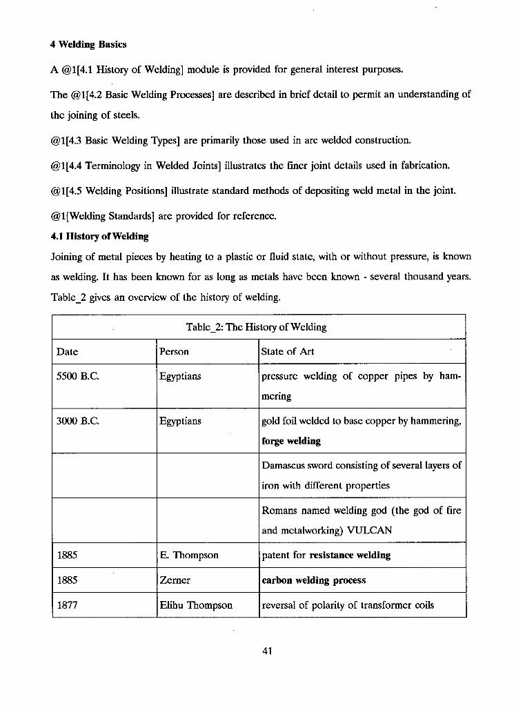
4 Welding Basics
A @1[4.1 History of Welding] module is provided for general interest purposes.
The @1[4.2 Basic Welding Processes] are described in brief detail to permit an understanding of
the joining of steels.
@1[4.3 Basic Welding Types] are primarily those used in arc welded construction.
@1[4.4 Terminology in Welded Joints] illustrates the finer joint details used in fabrication.
@1[4.5 Welding Positions] illustrate standard methods of depositing weld metal in the joint.
@1 [Welding Standards] are provided for reference.
4.1 History of Welding
Joining of metal pieces by heating to a plastic or fluid state, with or without pressure, is known
as welding. It has been known for as long as metals have been known - several thousand years.
Table_2 gives an overview of the history of welding.
Table_2: The History of Welding
Date Person State of Art
5500 B.C. Egyptians pressure welding of copper pipes by ham
mering
3000 B.C. Egyptians gold foil welded to base copper by hammering,
forge welding
Damascus sword consisting of several layers of
iron with different properties
Romans named welding god (the god of fire
and metalworking) V U L C A N
1885 E. Thompson patent for resistance welding
1885 Zerner carbon welding process
1877 Elihu Thompson reversal of polarity of transformer coils
41
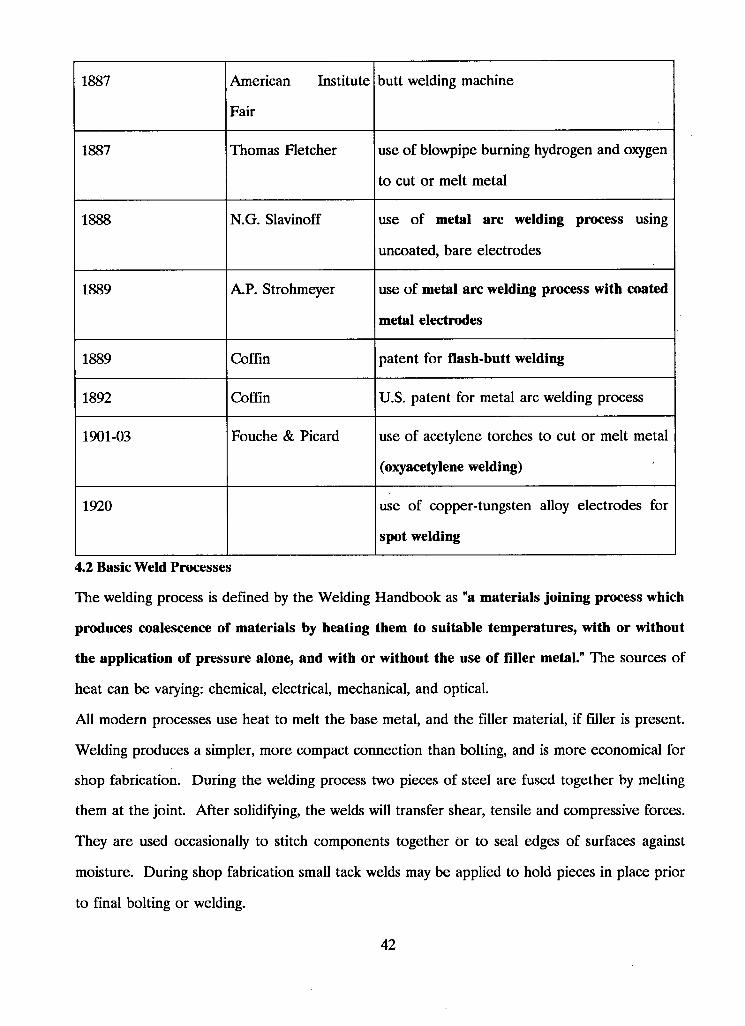
1887 American Institute
Fair
butt welding machine
1887 Thomas Fletcher use of blowpipe burning hydrogen and oxygen
to cut or melt metal
1888 N.G. Slavinoff use of metal arc welding process using
uncoated, bare electrodes
1889 A P . Strohmeyer use of metal arc welding process with coated
metal electrodes
1889 Coffin patent for flash-butt welding
1892 Coffin U.S. patent for metal arc welding process
1901-03 Fouche & Picard use of acetylene torches to cut or melt metal
(oxyacetylene welding)
1920 use of copper-tungsten alloy electrodes for
spot welding
4.2 Basic Weld Processes
The welding process is defined by the Welding Handbook as "a materials joining process which
produces coalescence of materials by heating them to suitable temperatures, with or without
the application of pressure alone, and with or without the use of filler metal." The sources of
heat can be varying: chemical, electrical, mechanical, and optical.
A l l modern processes use heat to melt the base metal, and the filler material, if filler is present.
Welding produces a simpler, more compact connection than bolting, and is more economical for
shop fabrication. During the welding process two pieces of steel are fused together by melting
them at the joint. After solidifying, the welds will transfer shear, tensile and compressive forces.
They are used occasionally to stitch components together or to seal edges of surfaces against
moisture. During shop fabrication small tack welds may be applied to hold pieces in place prior
to final bolting or welding.
42
We distinguish mainly between four types of welding processes for structural steel:
1. Electric Arc Welding - fusion process with heat from electric arc.
2. Resistance Welding - pressure process with heat from flow of current.
3. Oxyacetylene Gas Welding - fusion process with heat from acetylene burning in the presence
of oxygen.
4. Electroslag Welding - automatic machine welding process for primarily vertical position welding.
Other types of welding (induction-type welding, thermit welding, welding with optical or
mechanical energy, and solid state bonding) are not commonly used in structural steel fabrication.
4.2.1 Electric Arc Welding
Electric arc welding is the most important welding process, both in the shop and in the field. It
is performed manually (hand or stick welding) with a coated metal electrode (stick), or auto
matically with a continuous bare wire electrode. @1 [welbasl.pcx] illustrates the arc welded circuit.
The manual process is referred to as shielded metal arc welding (SMAW). @l[welbas2.pcx]
illustrates this process. An electric arc is produced between the end of the electrode and the
steel components to be welded. The arc heats the metal parts until they melt. As the arc is
moved along the line to be welded, the molten material solidifies and bonds the components
together. The electrode coating contains flux which purifies the molten metal and produces a
shielding gas to protect the molten metal from oxidization. Sometimes the shielding contains
other material, such as deoxidizers, to refine the grain structure of the weld material. The coating
remains on the weld surface in the form of a blanket, to protect the molten pool and the solidified
weld from oxygen and nitrogen in the air, and to retard cooling. This is the so called slag, which
must be removed before painting, by chipping or scraping.
This is the oldest, simplest, and perhaps most versatile type for welding structural steel. Often
one refers to SMAW as manual stick electrode process. The stick coating is a clay-like mixture
of silicate binders and powdered material, such as fluorides, carbonates, oxides, metal alloys, and
cellulose. The mixture is extruded and baked to produce a dry, hard, concentric coating.
43
An automatic process, known as submerged arc welding (SAW), is generally used in the fabri
cating shop. @1 [welbas3.pcx] illustrates this process. It is similar to the shielded arc welding.
The arc is not visible because it is covered by a blanket of granular, fusible flux while the bare
electrode is continuously fed by a machine and consumed as the filler material. Welds of con
sistently high quality and deeper penetration can be produced at a faster rate than would be
possible manually. Sometimes machines are set up to apply welds at several locations between
the components at the same time in order to avoid distortion owing to shrinkage during the
cooling process. Both manual and automatic processes can be modified by shielding the weld with
a special gas, usually carbon dioxide. Depending on the type of gas and electrode polarity, a
wide range of materials can be welded and many different weld penetrations are possible.
The flux covers the arc and prevents spatter, sparks, or smoke. It also protects the weld pool
from the atmosphere. The flux cleans and modifies the chemical composition of the weld metal.
Welds produced by this process usually have good ductility, high impact strength, small grain size,
and good corrosion resistance. The weld tensile strength is at least as good as that of the base
metal.
Gas metal arc welding process:
A more expensive and sophisticated method is the gas metal arc welding process (GMAW).
@ lfwelbas4.pcx] illustrates this welding process. Here a continuous wire is supplied from a coil
through an electrode holder, the gun. The shielding is supplied as a gas, mostly carbon dioxide
(GO2). It was developed as a method needing inert gases only, and got the name M I G (metal
inert gas). However, due to the high costs, mixtures of gases have become common. The mixtures
consist of argon, helium, and carbon dioxide, with ratios depending on the steel quality. Low alloy
steels can be welded with 3/4 argon and 1/4 carbon dioxide. When toughness of the weld is
required, a high percentage of helium (about 65 %), less argon (about 30%), and little carbon
dioxide (5%) is required.
The shielding gas has great control over the arc size, the metal transfer, the penetration, the
width of fusion, and the shape of the weld region. Furthermore it affects the speed of welding
and determines the undercutting. An experienced welder and/or exact weld recommendations are
extremely important in order to achieve high quality G M A W welds.
44
The affect of adding an inert gas to the inexpensive carbon dioxide is that the arc is made more
stable and the spatter during the metal transfer can be reduced. The higher the carbon dioxide
content, the lower the cost for the shielding gas, the higher the welding speed, and the better
the joint penetration.
Flux cored arc welding process:
A similar process is the flux cored arc welding process (FCAW). The continuously supplied wire
is here a thin tube, containing the flux material within its core. An "inverted" stick electrode
process is used here because, with the automatic supply of the wire, if the coating were on the
outside of the electrode it would peel off. Therefore, it is placed inside the tube. In certain
cases, additional CO2 is provided as shielding gas because it does not add considerably to the
welding costs, but does have the previously stated beneficial affects.
4.2.2 Resistance Welding
In resistance welding the heat is produced by resistance of the parts to an electric current. When
the components reach their melting temperature at the contact surfaces they fuse, and bond on
cooling. This type of welding is usually used in the fabrication of lighter steel components, such
as open-web steel joists, or for the application of steel cladding (spot welds).
4.23 Oxyacetylene Gas Welding
Gas welding is popular for minor repair work of difficult-to-reach structural components, because
it requires only relatively light equipment and no electric power source, unlike the methods
described above.
Generally, oxyacetylene torches are used to cut holes and to cut edges. When they are carefully
guided or automatically controlled they cut clean contours along straight or curved lines by fol
lowing templates or numerically input geometries. Great skill is needed to produce satisfactory
results, i.e. to avoid irregular surfaces, when the cutting is done by hand.
4.2.4 Electroslag Welding
Two wide, thick plates are best joined by an electroslag welding process (ESW). The weld is
made vertically from bottom to top in the weld cavity, to form a butt joint. Water-cooled copper
slides confine the molten slag and weld metal on each side of the joint as the weld is formed.
The heat is supplied by electric arcs and the weld electrodes are automatically fed in as the weld
45
progresses. The Arc can be extinguished once the process is under way so that the welding is
done by the heat produced through the resistance of the slag to the flow of current. Since
resistance heating is used for all but the initial heat source, the ESW process can't be counted
as an arc welding process.
This type of welding is preferred for applications requiring minimum distortion of the joined
members.
4.2.5 Stud Welding
The most commonly process of welding a metal stud to a base material is known as arc stud
welding, a fully automatic process which is similar to the SMAW process. The stud works as the
electrode and an electric arc is stretched from the end of the stud to the plate. A ceramic ferrule
around the end of the stud in the gun shields the arc. The setting gun is positioned and after a
short time of firing the arc, the gun pushes the stud into the molten pool. When the weld is
completed a small fillet has formed around the shank of the stud. The total time for setting one
stud can be less than a second.
43 Basic Welding Types
Primary attention is given here to the types of welds used predominantly in arc welded con
struction where the heat comes from an electric arc and no pressure is used.
There are three basic types of welds used to achieve an acceptable joint. These weld types are
termed G R O O V E , FILLET and P L U G (or SLOT). Welds are composed of one or more beads.
A bead is a single run or pass of weld metal. The diagram, @l[welbas5.pcx], shows the basic
weld types used in various applications. In preparation for the plug and slot welds, holes or slots
have been made in the upper plate. On relatively thinner material such welds can be made
without preparation and are called arc spot and arc seam welds.
43.1 Groove Welds
Welds are distinguished by their cross section. Approximately 20% of all structural welds are
groove welds. They are used when ends, edges and/or surfaces of two parts must be joined
together. The components to be joined are usually prepared by cutting or machining them to
provide square, vee, bevel, U- , or J-shaped grooves which are filled in by the weld material. We
46
further distinguish between complete and partial penetration welds, depending on the extent of
fusion throughout the depth of the joint.
As the name implies, the joints for such welds are in some manner prepared to form a groove
or crucible to receive the weld bead or beads. There are seven types defined in terms of shape:
square groove, V-groove, bevel groove, U-groove, J-groove, flare bevel and flare Vee.
@1 [welbas6.pcx] shows various types of groove welds as applied to butt joints. Some or all of
these welds are applicable also to corner joints, Tee joints, lap joints and edge joints. Also shown
are the flare bevel and flare Vee groove welds both of which tend to involve more specialized
applications. Both single groove and double groove joints can be prepared. Double grooves are
used for thick material.
Groove welds are classified in terms of two types of efficiency. One is a complete joint penetration
groove weld (CJPG) and the other is a partial joint penetration groove weld (PJPG). CJPG
welds are considered to be the most efficient type of weld. For matching "electrode - base metal"
conditions they readily develop the full capacity of the material.
43.2 Complete Joint Penetration Grooves
A complete joint penetration groove weld is defined as one welded from both sides or from one
side on a backing, having complete penetration and fusion of weld and base metal throughout
the depth of the joint. If welded from one side, steel backing must be used and full fusion into
it obtained. If welded from both sides, backgouging to sound metal is required before welding
to second side. See @1 [welbas7.pcx].
The complete joint penetration groove weld status can also be claimed for joints welded from
one side without backing, or with backing other than steel, as well as those welded from both
sides without backgouging if successfully qualified in a procedure test. The structural codes
provide for a great number of prequalified joint (geometries) details for CJPG welds for desig
nated welding processes.
In recognizing the special importance of these types of grooves and the related significance of
full development of the total cross-sectional area of the joint, the use of extension bars or run-off
plates is stipulated, when satisfactory termination at the ends by other means cannot be obtained.
Refer to @1 [welbas8.pcx].
47
433 Partial Joint Penetration Grooves
A partial joint penetration groove weld is defined primarily as one having joint penetration less
than complete. However, prequalified partial joint penetration grooves shall also include joints:
(a) Welded from one side without steel backing;
(b) Welded from both sides without back-gouging with very few exceptions related to either their
thicknesses or a deep penetrating welding process.
@1 [welbas9.pcx] illustrates the partial joint penetration groove weld.
It should be noted that all flare groove welds are officially designated as PJPG welds.
The allowable working strength of joints welded from one side only is restricted as compared to
that allowed for joints welded from both sides, or with a suitable backing bar. Moreover, a single
partial joint penetration groove weld shall not be subject to tension normal to the weld or to
bending about the longitudinal axis of the weld if it produces tension at the root of the weld.
See @l[welbasl0.pcx]. Other restrictions applicable to PJPG welds can be found in CSA W59
- M1989.
The effective size of PJPG welds, other than flare groove types, is a function of the angle at the
root of the joint and the root opening. For angles measured at the root equal to:
(1) 60 degrees or greater, the size is designated as equal to the depth of preparation.
(2) less than 60 degrees, but not less than 45 degrees, the size is designated as the depth of
preparation minus 3 mm (1/8 inch), when in both cases the root opening is zero.
43.4 Fillet Welds
Fillet welds are the most common type of weld (nearly 80% of all welds) because they require
little or no preparatory work. Their typical cross section is triangular. The leg of the triangle
designates the weld size. The root of a weld is at the intersection of the legs. A line perpendicular
to the weld face and passing through the root is called the weld throat, and the length of this
line is the throat size.
With root openings greater than zero deeper penetration is obtainable for the grooves with
smaller angles at the root.
48
This term is given to welds making lap, Tee joints or inside corner joints. Such welds may consist
of one or more beads or layers and are approximately triangular in cross section; they join two
surfaces, usually but not always, at right angles to each other in the above mentioned joints.
@ 1 [welbasll.pcx] shows the ideal fillet weld to be one where the joint faces are at 90 degrees,
the weld has equal legs, the face is flat or slightly convex and the toes merge smoothly with the
surfaces of the joint members.
To determine the effective cross-sectional area of a fillet weld, a triangle is inscribed into its
profile. For an equal-legged, right-angled fillet, the triangle will be isosceles while an unequal-
legged fillet will be any triangle. These inscribed triangles are used for the determination of
effective throats and effective leg sizes. Refer to @l[welbasl2.pcx].
Generally, the limitations on maximum size of fillet will be based on considerations of good
welding practice or balanced design. Minimum size fillets, on the other hand, are governed
primarily by strength but additionally by minimum thickness of material considerations as specified
in governing standards (CSA W59).
43.5 Plug Weld
Plug or slot welds are usually used in lap joints to transmit shear loads or to prevent buckling.
They are similar to fillet welds but their maximum shear capacity is limited by the projected slot
area. @1 [welbasl3.pcx] illustrates this weld type.
A descriptive term for this weld is rivet weld. They are employed chiefly for lap joints but may
be used for Tee joints on thick plate where a fillet weld is not adequate or is not possible due
to inaccessibility. When a slot is made rather than a circular hole the weld is called a slot weld.
It is a form of plug weld.
Usually a hole or slot is punched, drilled or flame cut in one plate and a weld made through it
to the underlying plate joining the two by a fillet weld around the periphery of the hole or slot.
The hole or slot may or may not be entirely filled in with weld metal. On relatively thin material
a hole or slot may not be necessary.
It should be emphasized that fillet welds in holes or slots are not to be confused with plug and
slot welds.
49
4.4 Terminology in Welded Joints
@l[welbasl4.pcx] shows a single V-groove weld in a butt joint to illustrate the correct terms used
in identifying the salient aspects of all welded joints. Appendix D of W59-M89 contains infor
mation on welding symbols.
4.5 Welding Positions
A weld is said to be made in the flat position, horizontal position, vertical position or overhead
position depending on the position of the joint in relation to the floor. Welding techniques for
the four positions of welding vary according to the ease of depositing metal. It is possible to
deposit weld layers of considerable volume in the flat and vertical positions but stringer beads
become necessary for horizontal and overhead welding. These positions are better illustrated in
@l[welbasl5.pcx].
4.6 Welding Standards
1. CSA Standard W59-M89, Welded Steel Construction (Metal-Arc Welding).
2. CAN3-S16.1-M89, Steel Structures for Buildings, Limit States Design.
3. CAN3-G40.20-M87, General Requirements for Rolled or Welded Structural Quality Steel.
5. CAN3-G40.21-M87, Structural Quality Steels.
6. W47.1 - 1983 Certification of Companies for Fusion Welding of Steel Structures.
7. W48.1 - M1980, Mild Steel Covered Arc Welding Electrodes.
8. W48.3 - M1982, Low-Alloy Steel Covered Arc Welding Electrodes.
9. W48.4 - M1980, Solid Mild Steel Filler Metals for Gas Shielded Arc Welding.
10. W48.5 - M1982, Mild Steel Electrodes for Flux Cored Arc Welding.
11. W48.6 - M1980, Bare Mild Steel Electrodes and Fluxes for Submerged Arc Welding.
12. W48.7 - M1977, Diffusible Hydrogen in Mild Steel and Low-Alloy Steel Weld Metals: Test
Method.
13. W55.3 - 1965, Resistance Welding Qualification Code for Fabricators of Structural Members
Used in Buildings.
14. W178 - 1973, Qualification Code for Welding Inspection Organizations.
50
5 Weldability of Steels
The prevention of cracks during welding or in service is first and foremost in maintaining structural
integrity. Special welding procedures are not usually required for a correctly designed joint and
properly made weld. However, there is a need for special procedures with heavy plate structural
members and steels having great amounts of alloying elements in their chemistry.
Weldability is defined in @1[5.1 Weldability].
5.1 Weldability
Weldability describes the relative ease of producing effective, sound and crack-free joints. Most
steels may be commonly arc welded to produce sound, secure welded joints. A steel is thought
to be ideally weldable if the required welded joint can be produced with relative easy and minimal
cost.
Although not necessary with the more common mild steels, preheating or some other measure
may be required when welding thick plates or higher-strength alloys.
Steel chemistry becomes more important with the use of high-speed welding. Even though the
composition of the electrode core wire is accurately controlled to produce good welds, the plate
metal becomes part of the weld and control of the plate chemistry is also important. Higher
currents may be used to achieve higher welding speeds, however, more of the plate metal will
now mix with the weld. If possible, select an easily welded steel that does not require special
electrodes or elaborate welding procedures. Table_3 gives a range of carbon steel composition
for maximum welding speed. This table was produced in 1966 and, although the numbers are
approximately correct, today's standards should be consulted to check for accuracy.
51
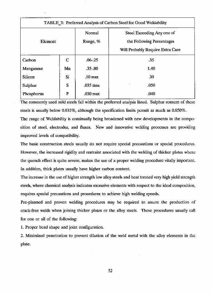
TABLE_3: Preferred Analysis of Carbon Steel for Good Wettability
Normal Steel Exceeding Any one of
Element Range, % the Following Percentages
Will Probably Require Extra Care
Carbon C .06-.25 .35
Manganese Mn .35-.80 1.40
Silicon Si .10 max .30
Sulphur S .035 max .050
Phosphorus P .030 max .040
The commonly used mild steels fall within the preferred analysis listed. Sulphur content of these
steels is usually below 0.035%, although the specification limits permit as much as 0.050%.
The range of Wettability is continually being broadened with new developments in the compo
sition of steel, electrodes, and fluxes. New and innovative welding processes are providing
improved levels of compatibility.
The basic construction steels usually do not require special precautions or special procedures.
However, the increased rigidity and restraint associated with the welding of thicker plates where
the quench effect is quite severe, makes the use of a proper welding procedure vitally important.
In addition, thick plates usually have higher carbon content.
The increase in the use of higher strength low alloy steels and heat treated very high yield strength
steels, where chemical analysis indicates excessive elements with respect to the ideal composition,
requires special precautions and procedures to achieve high welding speeds.
Pre-planned and proven welding procedures may be required to assure the production of
crack-free welds when joining thicker plates or the alloy steels. These procedures usually call
for one or all of the following:
1. Proper bead shape and joint configuration.
2. Minimized penetration to prevent dilution of the weld metal with the alloy elements in the
plate.
52
3. Preheating, controlled interpass temperature, and sometimes even controlled heat input from
the welding procedure to retard the cooling rate and reduce shrinkage stresses.
5.2 Base Procedure on Actual Composition
Published standard production welding procedures generally apply to normal welding conditions
and the more common "preferred composition" mild steels.
If the specification composition of the steel being welded falls outside the preferred composition,
the user may attempt to adopt a special welding procedure based on the extremes of the material's
chemical content "allowed" by the steel's specification. However, this action may prove super
fluous because the actual chemistry of a specific heat of steel may run far below the top limit of
the "allowables", and a special procedure may not be required, or may require only a slight change
from standard procedures.
For optimum economy and quality, under either favorable or adverse conditions, the welding
procedure for joining any type of steel should be based on the steel's actual chemistry rather
than the maximum alloy content allowed by the specification. This is because a mill's average
production normally runs considerably under the maximum limits set by the specification.
Usually a Mill Test Report is available which gives the specific analysis of any given heat of steel.
Once this information is obtained, a welding procedure can be set that will assure the production
of crack-free welds at the lowest possible cost.
S3 Weld Quality
The primary objective of any welding procedure is to fasten the pieces as required using the most
efficient weld possible while incurring minimal cost. "As required" means the weld's size and
quality must be consistent with service requirements. Extreme precautions to procure unnecessary
quality, beyond that needed to meet service requirements, only serve to increase costs.
Because it greatly increases cost without any benefit, inspection should not subsequently demand
the correction of nominal undercut or insignificant radiographic defects (Eg. limited scattered
porosity, slag inclusions) unless thorough study shows such defects cannot be tolerated because
of specific service requirements.
Weld quality is governed by W59-M89 under clause 11.5.4 Quality of Welds and clause 12.5.4
Quality of Welds for statically and dynamically loaded structures, respectively.
53
5.4 Weld Cracks and Their Prevention
A crack in a weld is never minor and cannot be condoned. Good design and proper welding
procedure will prevent the following cracking problems:
1. weld cracks occurring during welding.
2. cracking in the heat affected zone of the base metal,
3. welded joints failing in service.
5.4.1 Factors that Affect Weld Cracking During Welding
The following factors affect weld cracking during welding:
1. Joint Restraints that cause high stresses in the weld.
2. Bead Shape of the deposited weld. As the hot weld cools, it tends to shrink. A convex bead
has sufficient material in the throat to satisfy the demands of the biaxial pull. However, a concave
bead may result in high tensile stresses across the weld surface from toe to toe. These stresses
frequently are high enough to rupture the surface of the weld causing a longitudinal crack.
A n excessively penetrated weld with its depth greater than its width under conditions of high
restraint may cause internal cracks.
Both of these types of cracking are greatly aggravated by high sulphur or phosphorus content in
the base plate.
3. Carbon and Alloy Content of the base metal. The higher the carbon and alloy content of the
base metal, the greater the possible reduction in ductility of the weld metal through admixture.
This contributes appreciably to weld cracking.
4. Hydrogen Pickup in the weld deposit from the electrode coating, moisture in the joint, and
contaminants on the surface of the base metal.
5. Rapid Cooling Rate which increases the effect of items 3 and 4.
5.4.2 Factors that Affect Cracking in the Heat-Affected Zone
The following factors affect weld cracking in the heat affected zone:
1. High Carbon or Alloy Content which increases hardenability and loss of ductility in the
heat-affected zone. (Underbead cracking does not occur in non-hardenable steel.)
2. Hydrogen Embrittlement of the fusion zone through migration of hydrogen liberated from the
weld metal.
54
3. Rate of Cooling which controls items 1 and 2.
5.43 Factors that Affect Welded Joints Failing in Service
We generally refer to welds that break in service as a result of insufficient sizing rather than
welds that crack because welds do not usually crack in service. Two other factors might be:
1. Notch toughness, which would affect the breaking of the weld or the plate when subjected to
high impact loading at extremely low temperatures.
2. Fatigue cracking caused by a notch effect from poor joint geometry. This occurs under service
conditions of unusually severe stress reversals.
5.4.4 Items to Control Weld Cracking
1. Bead Shape. Proper bead surface (i.e. slightly convex) and proper width-to-depth ratio are
two important parameters to control when laying down a bead. This is not critical with single
pass welds or with the root pass of a multiple pass weld.
2. Joint Restraint. Design weldments and structures to keep restraint problems to a minimum.
3. Carbon and Alloy Content. Select the correct grade and quality of steel for a given application,
through familiarity with the mill analysis and the cost of welding. Suppress the percentage content
of elements like sulphur and phosphorus, whose presence adversely affect weld quality.
Avoid excessive admixture by reducing penetration. Procedural changes such as using different
electrodes, lowering currents, changing polarity, or improving joint design such as replacing a
square edge butt weld with a bevel joint, will all effectively reduce penetration.
4. Hydrogen Pickup. Select low-hydrogen welding materials.
5. Heat Input. Total heat input can be controlled by monitoring preheat, welding heat, heating
between weld passes to control interpass temperature and post heating to control cooling rate.
Control of heat input lowers the shrinkage stresses and retards the cooling rate. This will help
to prevent excessive hardening in the heat-affected zone.
5.5 Tack Welds
The use of tack welds is covered in clause 5.4.7 Tack Welds of W59-M89. In general, tack welds
that are incorporated into the final weld shall be subject to the same quality requirements of the
final weld, except that preheat is not necessary for single pass welds where it can be proven that
55
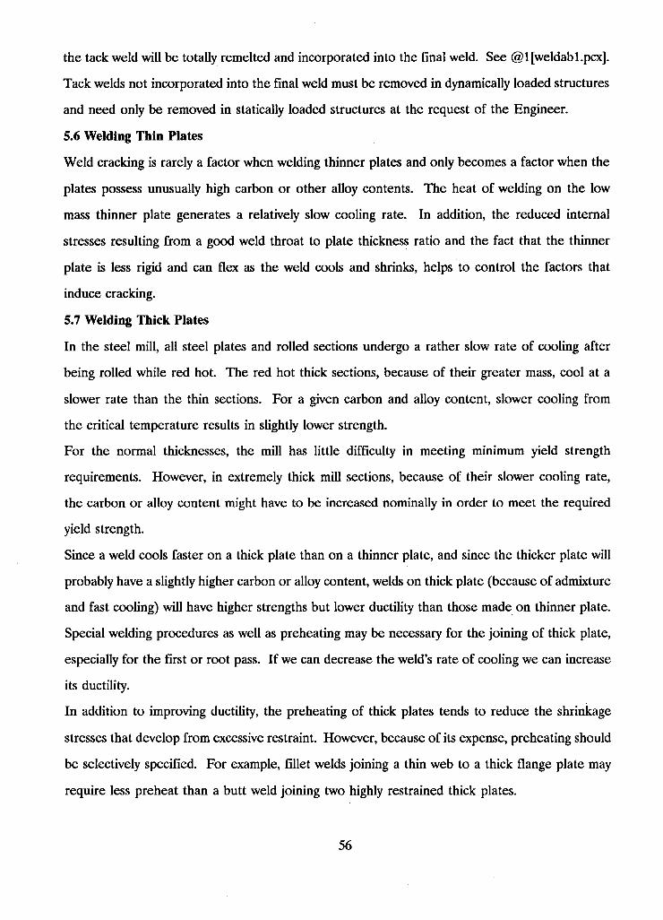
the tack weld will be totally remelted and incorporated into the final weld. See @1 [weldabl.pcx].
Tack welds not incorporated into the final weld must be removed in dynamically loaded structures
and need only be removed in statically loaded structures at the request of the Engineer.
5.6 Welding Thin Plates
Weld cracking is rarely a factor when welding thinner plates and only becomes a factor when the
plates possess unusually high carbon or other alloy contents. The heat of welding on the low
mass thinner plate generates a relatively slow cooling rate. In addition, the reduced internal
stresses resulting from a good weld throat to plate thickness ratio and the fact that the thinner
plate is less rigid and can flex as the weld cools and shrinks, helps to control the factors that
induce cracking.
5.7 Welding Thick Plates
In the steel mill, all steel plates and rolled sections undergo a rather slow rate of cooling after
being rolled while red hot. The red hot thick sections, because of their greater mass, cool at a
slower rate than the thin sections. For a given carbon and alloy content, slower cooling from
the critical temperature results in slightly lower strength.
For the normal thicknesses, the mill has little difficulty in meeting minimum yield strength
requirements. However, in extremely thick mill sections, because of their slower cooling rate,
the carbon or alloy content might have to be increased nominally in order to meet the required
yield strength.
Since a weld cools faster on a thick plate than on a thinner plate, and since the thicker plate will
probably have a slightly higher carbon or alloy content, welds on thick plate (because of admixture
and fast cooling) will have higher strengths but lower ductility than those made on thinner plate.
Special welding procedures as well as preheating may be necessary for the joining of thick plate,
especially for the first or root pass. If we can decrease the weld's rate of cooling we can increase
its ductility.
In addition to improving ductility, the preheating of thick plates tends to reduce the shrinkage
stresses that develop from excessive restraint. However, because of its expense, preheating should
be selectively specified. For example, fillet welds joining a thin web to a thick flange plate may
require less preheat than a butt weld joining two highly restrained thick plates.
56
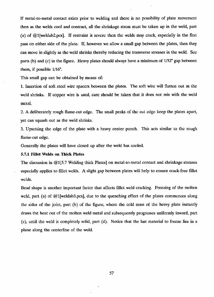
If metal-to-metal contact exists prior to welding and there is no possibility of plate movement
then as the welds cool and contract, all the shrinkage stress must be taken up in the weld, part
(a) of @l[weldab2.pcx]. If restraint is severe then the welds may crack, especially in the first
pass on either side of the plate. If, however we allow a small gap between the plates, then they
can move in slightly as the weld shrinks thereby reducing the transverse stresses in the weld. See
parts (b) and (c) in the figure. Heavy plates should always have a minimum of 1/32" gap between
them, if possible 1/16".
This small gap can be obtained by means of:
1. Insertion of soft steel wire spacers between the plates. The soft wire will flatten out as the
weld shrinks. If copper wire is used, care should be taken that it does not mix with the weld
metal.
2. A deliberately rough flame-cut edge. The small peaks of the cut edge keep the plates apart,
yet can squash out as the weld shrinks.
3. Upsetting the edge of the plate with a heavy center punch. This acts similar to the rough
flame-cut edge.
Generally the plates will have closed up after the weld has cooled.
5.7.1 Fillet Welds on Thick Plates
The discussion in @1[5.7 Welding thick Plates] on metal-to-metal contact and shrinkage stresses
especially applies to fillet welds. A slight gap between plates will help to ensure crack-free fillet
welds.
Bead shape is another important factor that affects fillet weld cracking. Freezing of the molten
weld, part (a) of @1 [weldab3.pcx], due to the quenching effect of the plates commences along
the sides of the joint, part (b) of the figure, where the cold mass of the heavy plate instantly
draws the heat out of the molten weld metal and subsequently progresses uniformly inward, part
(c), until the weld is completely solid, part (d). Notice that the last material to freeze lies in a
plane along the centerline of the weld.
57
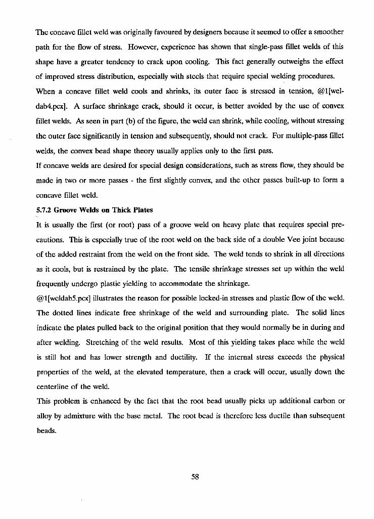
The concave fillet weld was originally favoured by designers because it seemed to offer a smoother
path for the flow of stress. However, experience has shown that single-pass fillet welds of this
shape have a greater tendency to crack upon cooling. This fact generally outweighs the effect
of improved stress distribution, especially with steels that require special welding procedures.
When a concave fillet weld cools and shrinks, its outer face is stressed in tension, @l[wel-
dab4.pcx]. A surface shrinkage crack, should it occur, is better avoided by the use of convex
fillet welds. As seen in part (b) of the figure, the weld can shrink, while cooling, without stressing
the outer face significantly in tension and subsequently, should not crack. For multiple-pass fillet
welds, the convex bead shape theory usually applies only to the first pass.
If concave welds are desired for special design considerations, such as stress flow, they should be
made in two or more passes - the first slightly convex, and the other passes built-up to form a
concave fillet weld.
5.7.2 Groove Welds on Thick Plates
It is usually the first (or root) pass of a groove weld on heavy plate that requires special pre
cautions. This is especially true of the root weld on the back side of a double Vee joint because
of the added restraint from the weld on the front side. The weld tends to shrink in all directions
as it cools, but is restrained by the plate. The tensile shrinkage stresses set up within the weld
frequently undergo plastic yielding to accommodate the shrinkage.
@1 [weldab5.pcx] illustrates the reason for possible locked-in stresses and plastic flow of the weld.
The dotted lines indicate free shrinkage of the weld and surrounding plate. The solid lines
indicate the plates pulled back to the original position that they would normally be in during and
after welding. Stretching of the weld results. Most of this yielding takes place while the weld
is still hot and has lower strength and ductility. If the internal stress exceeds the physical
properties of the weld, at the elevated temperature, then a crack will occur, usually down the
centerline of the weld.
This problem is enhanced by the fact that the root bead usually picks up additional carbon or
alloy by admixture with the base metal. The root bead is therefore less ductile than subsequent
beads.
58
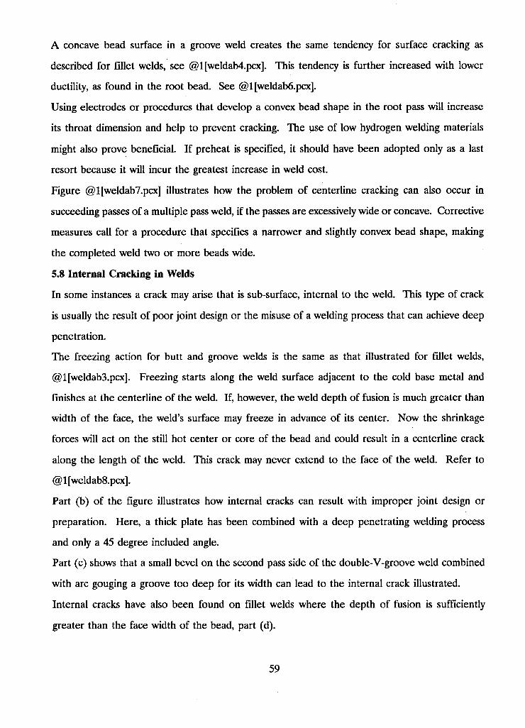
A concave bead surface in a groove weld creates the same tendency for surface cracking as
described for fillet welds, see @1 [weldab4.pcx]. This tendency is further increased with lower
ductility, as found in the root bead. See @1 [weldab6.pcx].
Using electrodes or procedures that develop a convex bead shape in the root pass will increase
its throat dimension and help to prevent cracking. The use of low hydrogen welding materials
might also prove beneficial. If preheat is specified, it should have been adopted only as a last
resort because it will incur the greatest increase in weld cost.
Figure @1 [weldab7.pcx] illustrates how the problem of centerline cracking can also occur in
succeeding passes of a multiple pass weld, if the passes are excessively wide or concave. Corrective
measures call for a procedure that specifies a narrower and slightly convex bead shape, making
the completed weld two or more beads wide.
5.8 Internal Cracking in Welds
In some instances a crack may arise that is sub-surface, internal to the weld. This type of crack
is usually the result of poor joint design or the misuse of a welding process that can achieve deep
penetration.
The freezing action for butt and groove welds is the same as that illustrated for fillet welds,
@1 [weldab3.pcx]. Freezing starts along the weld surface adjacent to the cold base metal and
finishes at the centerline of the weld. If, however, the weld depth of fusion is much greater than
width of the face, the weld's surface may freeze in advance of its center. Now the shrinkage
forces will act on the still hot center or core of the bead and could result in a centerline crack
along the length of the weld. This crack may never extend to the face of the weld. Refer to
@1 [weldab8.pcx].
Part (b) of the figure illustrates how internal cracks can result with improper joint design or
preparation. Here, a thick plate has been combined with a deep penetrating welding process
and only a 45 degree included angle.
Part (c) shows that a small bevel on the second pass side of the double-V-groove weld combined
with arc gouging a groove too deep for its width can lead to the internal crack illustrated.
Internal cracks have also been found on fillet welds where the depth of fusion is sufficiently
greater than the face width of the bead, part (d).
59
Internal cracks should give cause for concern because they cannot be detected with visual
inspection methods, however, a few preventive measures can assure their elimination. Limiting
the penetration and the volume of weld metal deposited per pass through speed and amperage
control is one positive control method. Using a joint design which sets reasonable depth of fusion
requirements is another.
The most important factor to help control internal cracking is the ratio of weld width to depth.
Experience has shown that a weld width to depth of fusion ratio in the range from a minimum
of 1:1 to a maximum of 1.4:1 proves most satisfactory.
5.9 Underbead Cracking
Underbead cracking is not a problem with the controlled composition, low carbon steels. When
it does occur, it shows up in the heat-affected zone of the base metal. Higher carbon or alloy
contents in thick plates provide a suitable environment for this type of cracking. For example,
construction alloy steels which have over 100,000 psi tensile strength and are heat treated before
welding may experience underbead cracking in thick plates. Underbead cracking is generally only
important on hardenable steels.
One cause of underbead cracking is hydrogen embrittlement in the heat-affected zone. As a
result, low-hydrogen processes should be used to join these materials. Hydrogen in the welding
arc, either from the electrode coating or from wet or dirty plate surfaces, will tend to be partially
absorbed into the droplets of weld metal before deposit and absorption into the molten metal
beneath the arc.
Recently deposited and solidified hot weld metal and the adjacent now heated base metal are
both austenitic at this elevated temperature, and therefore have a high solubility for hydrogen.
Although, a considerable portion of hydrogen escapes through the weld's surface into the air, a
small amount may diffuse back through the weld into the adjacent base metal. The rate of
hydrogen diffusion decreases with decreasing temperature.
Beyond the boundary of the heat-affected zone, the base metal is in the form of ferrite, which
has practically no solubility for hydrogen. This low solubility ferrite boundary becomes an
imaginary barrier and the hydrogen tends to pile up here with no where else to go. See
@ 1 [weldab9.pcx].
60
Upon further cooling, the once austenitic area transforms back to ferrite with almost no solubility
for hydrogen. The existing hydrogen now tends to separate out between the crystal lattice and
build up pressure. This pressure, when combined with shrinkage stresses and any hardening effect
of the steel's chemistry, may cause tiny cracks. Because the weld metal generally contains less
carbon than the base plate, the problem arises just beyond the weld along the once existing
austenite-ferrite boundary and is called "underbead cracking". See @l[weldabl0.pcx]. If these
cracks reach the plate surface adjacent to the weld, they are called "toe cracks".
Reduced welding speeds and the application of preheat both tend to slow down the cooling
process thereby permitting more time for the hydrogen to escape. The reduction in hydrogen
through the process just described or, even better, the use of low-hydrogen welding materials will
essentially eliminate the problem of underbead cracking.
5.10 Reasons to Preheat
Preheating, while not always necessary, is used for one of the following reasons:
1. To reduce shrinkage stresses in the weld and adjacent base metal; especially important in highly
restrained joints.
2. To provide a slower rate of cooling through the critical temperature range (about 980 to 720
degrees Celsius) preventing excessive hardening and lowered ductility in both weld metal and
heat-affected area of the base plate.
3. To provide a slower rate of cooling through the 200 degree Celsius range, allowing more time
for any hydrogen that is present to diffuse away from both the weld and adjacent plate and as a
result, avoid underbead cracking.
4. To increase the allowable critical rate of cooling below which there will be no underbead
cracking. Thus, with the welding procedure held constant, a higher initial plate temperature
increases the maximum safe rate of cooling while slowing down the actual rate of cooling. This
tends to make the heat input from the welding process less critical.
5. To increase the notch toughness in the weld zone.
6. To lower the transition temperature of the weld and adjacent base metal.
61
Normally, not much preheat is required to prevent underbead cracking and even less is required
when low-hydrogen welding materials are used. Higher preheat temperatures, however, may
occasionally be required for some other reason, such as, a highly restrained joint between very
thick plates, or high alloy content in the base plate.
Preheating makes other factors less critical, but since it invariably increases the cost of welding,
it should not be indulged in unnecessarily.
62
6 Maintaining Control Over Welding
This local section of the hypertext base discusses,
@1[06.1 Residual Stresses]
@1[06.2 Shrinkage and Distortion]
@1[06.3 Summary and Check List]
@1[06.4 Lamellar Tearing]
6.1 Residual Stresses
Residual stresses are those stresses that remain in a body after all external loads have been
removed. The following technical terms have been used to denote residual stresses:
Internal stresses
Initial stresses
Inherent stresses
Reaction stresses
Locked-in stresses
In addition, the residual stresses remaining in a body subjected to a non-uniform temperature
change are called thermal stresses. Thermal stresses arise when temperature change is accom
panied by restraint.
Occurrence of Residual Stresses:
Unfortunately, the manufacturing of metal structures permits the creation of residual stresses in
many ways. Rolling, casting, or forging of materials such as plates, bars, and sections can produce
significant residual stresses. In addition, shearing, bending, machining, and grinding during the
forming and shaping of metal parts may also produce substantial stresses. Another way to produce
residual stresses is through fabrication processes such as welding. The manufacturing process
may involve heat treatments such as quenching which produces residual stress or stress-relieving
which alleviates residual stress.
The complex temperature changes associated with the welding process cause transient thermal
stresses in the weldment thereby producing non-elastic or incompatible strains in regions near
63
the weld. It is these strains that generate residual stresses upon completion of welding. Residual
stresses produced from the welding process may be classified into two categories according to the
mechanisms which created them:
1. Reaction stresses - The restraining effect comes from external sources. These stresses
extend well away from the weld with magnitude determined mainly by the degree of external
restraint. Reaction stresses might more informatively be described as 'suppression of distortion'
stresses.
2. Residual stresses - The restraining effect comes from the colder metal adjacent to the
weld. These stresses are in equilibrium over a relatively small range and are more difficult to
control.
@1[06.1.2 Residual and Reaction Stresses in a Butt Weld] illustrate the distribution of longitu
dinal and transverse stresses.
6.1.1 Discussion of Residual Stresses
An unrestrained, uniformly heated material will expand uniformly, without the production of
thermal stress. The generation of thermal stress requires non-uniform heating and expansion of
a material. Further, if transient thermal stresses are completely elastic and no incompatible strains
are formed, no residual stresses will remain. However, non-elastic or incompatible strains are
produced during welding and once the weld is completed, residual stresses remain. Residual
stresses may also result from unevenly distributed non-elastic strains such as plastic strains.
Residual stresses are generated in structural members as a consequence of localized plastic
deformation. In other words, the failure of the member, or part of the member, to relax to an
unstressed condition after experiencing plastic deformation results in residual stress. For example,
the material contractions that occur in rolled structural shapes as they cool from rolling tem
perature down to ambient room temperature will result in plastic deformations because some
parts of the shape cool much faster than others. Inelastic deformations are predominant in the
slower cooling portions.
Similar analogies may be shown for welded members and heat-treated bars that are not
furnace-cooled. Also, cold-straightened members contain residual stresses as a result of the
applied plastic bending deformations
64
In general, without plastic deformation during the life of the material there can be no residual
stresses. Furthermore, for elements experiencing a temperature gradient, the part to cool last
will usually be in a state of tensile residual stress.
Equilibrium Condition:
Residual stresses exist without any applied external forces. Therefore, there must be no resultant
force or resultant moment produced by the residual stresses.
§ s*dA = 0 on any plane section
§ dM = 0
6.1.2 Residual and Reaction Stresses in a Butt Weld
Three diagrams will be used to illustrate residual stresses in a butt welded plate. @1 [resid30.pcx]
shows the butt weld orientation and stress directions. @l[resid31.pcx] and @l[resid32.pcx] show
the most important residual stress distributions, stress parallel to the weld direction and stress
transverse to it, respectively.
In @1 [resid31.pcx], the distribution of longitudinal residual stress shown indicates large magnitude
tensile stress in the region near the weld tapering off rapidly to compressive stresses several weld
widths away. This distribution may be characterized by the maximum tensile stress at the weld,
s, and the width of the tension zone, b. In low carbon steel weldments, the maximum residual
tensile stress, s, is usually as high as the yield stress of the weld metal.
According to Masubuchi and Martin, the following equation may be used to approximate the
longitudinal residual stress.
s (y) = s {1 - (y/b)2} e EXP(-V4(y/b)2)
Curve 1 of @l[resid32.pcx] illustrates the distribution of transverse residual stress along the length
of the weld. Low magnitude tensile stresses are shown along the middle section of the joint with
compression stresses at the ends of the joint.
Curve 2 of the same diagram represents the reaction stress distribution that would exist if the
lateral contraction of the joint was restrained by an external constraint. Note that the added
tensile stresses are approximately uniform along the length of the weld.
As an added note, an external constraint would have little influence on the distribution of lon
gitudinal stress.
65
6.13 Residual Stress in Columns
The measurement of residual stresses in WF shapes of ASTM-A7 designation was found to be,
on average, of about 13 ksi compression at the tips of the flanges and about 5 ksi tension at the
center.
With regard to WF shapes welded from universal mill plates, a significantly high increase in the
residual tensile stress at the flange-to-web junction generates correspondingly higher residual
compressive stresses at the extremes of the flanges. The tensile residual stresses will frequently
approach the yield stress of the material, while the residual compressive stresses reach about
two-thirds of this value.
A typical distribution of residual stresses in two of the more common welded column sections,
H-shape and Box-shape, is shown in the following figures. Refer to @l[resid2.pcx] and
@1 [resid3.pcx].
The existence of high compressive residual stresses at critical locations on the section may reduce
the buckling strength of a column considerably. Therefore, the magnitude and distribution of
residual stresses in the component parts of the built-up shape, as the result of welding, are
important.
Beedle and Galambos wrote a paper on the influence of residual stress on concentrically loaded
columns. The following three points summarize the research on this topic:
1. Residual stresses due to: cooling after rolling, welding, cold bending, and various heat treatment
processes, have a pronounced effect on the stress-strain curve, and generally decrease the load
carrying capacity of columns.
2. Residual stresses in rolled shapes do not appear to be influenced by the level of yield stress.
Thus, the higher strength steel columns show less reduction in strength because of residual stress.
3. Residual stresses due to full strength welds are usually greater than those set up by cooling
after rolling. As a result, the column strength of welded "H" shapes is less than that of rolled
WP shapes for columns of intermediate lengths. However, since geometry plays an important
role, tests show that box shapes give higher strength. Further research on the influence of
geometry and of weld size will shed more light on the problem.
66
Recent studies have revealed that flame cutting of plates to be used in compound WF sections
can favorably affect the residual stress distribution. This trend is illustrated in @1 [resid4.pcx]
and @1 [resid5.pcx]. High tensile residual stresses induced into the cut edge of the flange plate
prior to welding of the web flange connection will considerably reduced the residual compressive
stresses that would otherwise be produced in the flange tips, if not totally eliminate them.
Increased strengths of columns have been reported to be 5 to 10 percent.
Furthermore, flame cutting of the flange plates after the welding of the web plate, which may
be less practical but feasible, is reported to improve still further the stress distribution in a column,
@1 [resid6.pcx]. This procedure may result in a strengths slightly higher than those of rolled
sections.
Another simple method to obtain a favorable residual stress pattern in welded WF columns is to
apply a weld bead to the toes of the flanges during shop fabrication, or on site, as shown in
@ 1 [resid9.pcx].
Reinforcement of welded columns already in service, by the welding on of cover plates, is another
way to improve their strength. The side welds on the cover plates reverse the unfavorable residual
stress distribution at the toes of the flanges, as shown in @l[resid8.pcx].
@1 [resid7.pcx] shows the standard stress distribution of a medium sized built up H-shape before
any stress reduction techniques have been applied.
6.1.4 Residual Stress in Flexural Members
The distribution of residual stresses associated with the welded fabrication of built-up flexural
members, in general, has been found to depend on the following factors:
1. The geometry of the plates
2. The type and heat of welding
3. The speed of welding
4. The rate of cooling
Of these four, geometry clearly proves to have the greatest effect.
The results of an experimental investigation into the magnitude and distribution of longitudinal
residual stresses arising in plates due to edge and center welding, as summarized by Nagaraja and
Tall, are:
67
1. The distribution of residual stresses in all plates (ASTM-A7, 4 in. to 20 in. wide and 1/4 in.
to 1 in. thick), whether due to cooling from rolling in the unwelded plates or due to cooling from
welding in the welded plates, is approximately parabolic in shape, except at the weld itself. This
is true for welded plates up to about 16 in. in width.
2. The first pass causes the major portion of the residual stress to occur, and there is no great
variation of residual stress in welded plates between subsequent passes. At the edge, however,
the effect of succeeding passes of welds is quite marked.
3. Where the welding conditions are uniform along the plate, the residual stresses are also uniform
along the length of the plate (except at the start and termination of the weld).
4. Welding changes the properties of the plate material only in the vicinity of the weld. The
most important change is that the yield stress level is increased by about 50%. Because of higher
residual tensile stresses, this requires a proportionate increase in the compressive residual stresses
somewhere in the distribution.
5. Plates of less than 1/2 in. thickness show the same longitudinal residual stresses on both faces.
In the case of plate girders, the bending strength is provided mainly by flanges. Since it is the
yielding in the compression flange which determines its own individual strength, the residual
compressive stresses in that flange due to welding, which influences this yielding, may be taken
as affecting to some extent the bending strength of the girder.
However, whether it is a case of residual compressive stresses in the compression flange, or of
residual tensile stresses in the web-to-flange joint, the effects of residual stresses on the flexural
strength of welded members is generally considered negligible.
Residual stresses do not influence the strength of welded connections, with the exception of
bracing or stiffening requirements for compression elements.
6.2 Shrinkage and Distortion
Residual stresses, shrinkage, and distortion are closely related phenomena. During welding, the
heating and cooling cycle produces thermal strains both in the weld metal and base metal regions
near the weld. These heating strains result in plastic upsetting of the material. The stresses
generated from those strains combine and react to produce internal forces that cause bending,
buckling, and rotation. These weldment deformations are called distortions.
68
6.2.1 Welding Factors ThaA Cause Movement
The complex heating and cooling cycle is an unavoidable aspect of welding that must be controlled
and designed for. This temperature cycle will always cause shrinkage in both base metal and
weld metal. The internal forces set up as a result of this shrinkage can cause varying degrees of
distortion. Designers and engineers must anticipate and provide control of this shrinkage to
achieve the full economies of arc-welded steel construction.
The enormous temperature differential in the arc area creates a non-uniform distribution of heat
in the weldment. As temperature increases, there is a corresponding increase in the coefficient
of thermal expansion and the specific heat, while properties such as yield strength, the modulus
of elasticity, and the thermal conductivity decrease. Anticipation of material movement from a
straight forward analysis of heat is difficult at best.
Other factors to be considered are restraint from external clamping, internal restraint due to
mass, and the stiffness of the steel plate itself. Al l these factors have a definite influence on the
degree of movement.
Finally it is necessary to consider the factor of time as it affects the rapidly changing conditions.
The period of time during which a specific condition is in effect controls the importance of that
condition.
Further influence of shrinkage and distortion arises from the different welding procedures. The
type and size of electrode, welding current, speed of travel, joint design, and preheating and
cooling rates all bear significantly on the problem.
It is obvious that distortion cannot be analyzed by viewing each one of these factors separately.
A solution based on correcting the combined effect is the only practicable approach.
6.2.2 Weld Metal Shrinkage
The weld metal is in its maximum expanded state, or occupies the greatest volume it can occupy,
right at the point in time where it solidifies and fuses with the base metal. During the process
of cooling the weld metal would like to occupy a smaller volume, however it is prevented from
doing so by the adjacent base metal. This restraining effect leads to the development of stresses
within the weld which eventually reach the yield strength of the weld metal. The weld is then
forced to stretch, or yield, and thin out as it attempts to adjust to the volume requirements of
69
the joint being welded. Only the stresses which exceed the yield strength of the weld metal will
be relieved by this stretching effect. Upon reaching room temperature, and assuming the base
plates are fully restrained, there will exist locked-in tensile stresses equal in magnitude to the
yield strength of the weld metal. If the restraints are then released, the locked-in stresses will
find partial relief through movement of the base metal thus deforming or distorting the weldment.
@1 [residl0.pcx] illustrates the residual longitudinal and transverse stresses that arise with the
creation of a fillet weld. To picture how these stresses get into the weld, it is helpful to imagine
the situation depicted in @l[residll.pcx]. Here the fillet welds are considered independently of
the base plates. The weld metal is shown shrunk down to the volume it would occupy at room
temperature. It is both restraint and stress free. You can further imagine what has to be done
to the weld in order to attach it to the base plates. This action would require stretching in both
the longitudinal and transverse directions thereby generating stresses equal to the yield strength
of the weld material.
6.23 Base Metal Shrinkage
The build up of stresses that lead to distortion is further influenced by shrinkage in the base
metal adjacent to the weld. The heat of welding causes the base metal in the vicinity of the weld
to reach melting temperatures. However, only a few inches away the metal is substantially cooler.
This sharp temperature differential will cause non-uniform expansion followed by base metal
movement, or metal displacement if the parts being joined are restrained. Upon cooling the base
metal will shrink and any restraint from surrounding metal will lead to internal stress build up.
The tendency to distort is then increased as these stresses act in combination with those developed
in the weld metal.
Welding procedures are often used to control the volume of adjacent base metal contributing to
the distortion. The amount of adjacent base metal that is affected by the heat of the arc can be
reduced by using welding processes that achieve higher welding speeds. Less affected base metal
means less distortion.
According to studies on the mechanisms of transverse shrinkage in butt welds, the major portion
of the shrinkage is due to contraction of the base plate. Shrinkage of the weld metal itself only
accounts for about 10 percent of the actual shrinkage.
70
6.2.4 Fundamental Modes of Distortion
The welding process generates dimensional changes that lead to distortion in fabricated structures.
Three of the more fundamental dimensional changes are:
1. Transverse shrinkage perpendicular to the weld line.
2. Longitudinal shrinkage parallel to the weld line.
3. Angular distortion (rotation around the weld line).
The appearance of the dimensional change gives rise 6 classifications:
(a) Transverse shrinkage. Shrinkage perpendicular to the weld line. @l[residl2.pcx]
(b) Angular change (transverse distortion). A non-uniform thermal distribution in the thickness
direction causes distortion (angular change) close to the weld line. @l[residl3.pcx]
(c) Rotational distortion. Angular distortion in the plane of the plate due to thermal expansion.
@1 [residl4.pcx]
(d) Longitudinal shrinkage. Shrinkage in the direction of the weld line. @l[residl5.pcx]
(e) Longitudinal bending distortion. Distortion in a plane through the weld line and perpendicular
to the plate. @l[residl6.pcx]
(f) Buckling distortion. Thermal compressive stresses cause instability when the plates are thin.
@l[residl7.pcx]
6.2.4.1 Transverse Shrinkage of Butt Welds
Typical transverse shrinkage can be seen in @l[residl2.pcx]. This diagram shows uniform
shrinkage along the length of the weld, however, this is not usually the case. The real weldment
will exhibit complex transverse shrinkage which, for butt welds, is primarily dependent on rota
tional distortion and restraint.
Rotational distortion will occur as a result of progressive welding from one end of the joint to
the other. The reason being that the unwelded portion of the joint will move during this pro
cedure. See @1 [residl4.pcx]. Both the welding heat input and the location of tack welds effect
rotational distortion. Tack welds must be large enough to withstand the stresses caused by the
rotational distortion. The separating force caused by the rotational distortion can be large enough
to fracture the tack welds and crack portions of the weld metal. The largest amount of distortion
will be seen during the first pass when the unwelded portions of the joint are relatively free.
71
The degree of restraint applied to the weld joint will affect the magnitude of transverse shrinkage.
We can represent the external restraint by a system of springs whose rigidity describes the degree
of restraint. @1 [residl8.pcx] illustrates this simple principle. As the degree of restraint increases,
the amount of shrinkage decreases, and vice versa. The degree of restraint is not always uniform
along the length of the weld. For example, in a slit weld, the transverse shrinkage is restrained
by the bare metal surrounding the weld. The ends of the slit provide a high degree of restraint
resulting in minimal transverse shrinkage. The center of the slit, however, imparts a significantly
lower degree of restraint which yields much higher transverse shrinkage.
Consider a single pass butt weld in a free joint. Almost immediately after welding, the heat of
the weld metal is transmitted into the base metal. This transferral of heat results in the contraction
of the weld metal and the expansion of the base metal. This volume expansion of the base metal
is accommodated mostly through a change in thickness. So far, no sectional movement of the
base plate has occurred. In fact, it is not until the weld metal begins to resist the thermal
deformation of the base metal, time t = t(s), that the plate sections begin to move in response.
In other words, the contraction of the heated base metal, through cooling, begins to be resisted
by the weld metal, which is now developing tensile stresses, and therefore base plate sections
must move in. Subsequent contraction in the weldment commences as the heat leaves the base
plates. Ignoring the mathematical determination of the various thermal deformations of both
base plate and weld metal, we will jump to the conclusion. The final transverse shrinkage depends
on the thermal expansion of the base metal at time t(s) and on the thermal contraction of the
weld metal. Studies have shown weld metal shrinkage to account for only about 10 percent of
the actual shrinkage. Therefore, the most important factor in the final shrinkage of a single pass
butt weld in a free joint is the expansion of the base metal at time t(s).
The charts in @1 [residl9.pcx] and @1 [resid20.pcx] throw some light on transverse shrinkage. In
the latter chart, transverse shrinkage for a given plate thickness is seen to vary directly with the
cross-sectional area of the weld. The large included angles only help to illustrate this relationship
and do not represent common practice. The relative effects of single and double V-joints are
72
seen in the former chart. Both charts assume no unusual restraint of the plates against transverse
movement. Calculations show that transverse shrinkage is about 10% of the average width of
the cross-section of the weld area,
shrinkage = S = 0.10 * (Aw) / (t)
Although the above formula has been used for many years, alternative formulas have been
proposed. For example, Spraragen and Ettinger, after examining the shrinkage data obtained
from several earlier investigators, developed the following:
shrinkage = S = 0.2 * (Aw) / (t) + 0.05 * (d)
where: S = transverse shrinkage (in.)
Aw = cross-sectional area of weld (in.2)
t = thickness of plate (in.)
d = free distance or root opening (in.)
The moral, of course, is that transverse weld shrinkage calculation is not an exact science.
However, it is a well known fact that transverse shrinkage decreases when a joint is restrained.
Kihara and Masubuchi have studied multiple pass welding of butt joints in carbon steel. Their
results show that transverse shrinkage increases during multiple pass welding. This result is
illustrated in @l[resid21.pcx]. It was found that shrinkage diminished with subsequent weld passes
because the resistance against shrinkage increased as the weld got larger. A linear relationship
was then discovered between the transverse shrinkage, s, and the logarithm of the weight of the
weld metal, w. See @l[resid22.pcx].
s = s(0) + b * (log w - log w(0))
where: s = transverse shrinkage
s(0) = shrinkage after the first pass
w = total weight of weld metal per unit length
w(0) = weight of weld metal per unit length after the first pass
b = a coefficient
The most important procedural factors that affect transverse shrinkage are listed below:
1. Transverse shrinkage increases with weld volume.
2. Transverse shrinkage increases with increasing root gap.
73
3. Transverse shrinkage increases with total heat input.
4. Transverse shrinkage decreases with block welding.
6.2.4.2 Transverse Shrinkage of Fillet Welds
Fillet welds undergo less transverse shrinkage than butt welds. Although the amount of study
on this topic is limited, Spraragen and Ettinger have suggested the following simple formula:
1. Tee-joints with continuous fillets
shrinkage = [ (leg of fillet) / (thickness of plate) ] * 0.04 (in.)
2. Intermittent welds - apply correction factor of proportional length of fillet to total length
3. Fillets in lap joints (2 welds)
shrinkage = [ (leg of fillet) / (thickness of plate) ] * 0.06 (in.)
6.2.43 Longitudinal Shrinkage
Longitudinal shrinkage in butt welds:
Generally, longitudinal shrinkage from a butt weld amounts to approximately one one-thousandth
of the weld length. This is much less than the transverse shrinkage. Although research is limited,
King proposed the following formula:
shrinkage = s = [ 0.12 * I * L ] / [ 100000 * t ] (inches)
where: I = current (amps)
L = weld length (in.)
t = plate thickness (in.)
Longitudinal shrinkage of fillet welds:
Extensive research has been conducted by Guyot on the longitudinal shrinkage of fillet welds in
carbon steel. Guyot discovered that the total cross-section of the joints involved will primarily
govern the magnitude of longitudinal shrinkage. Thicker and wider plates will provide more
effective restraint. Therefore, Guyot decided to call the total cross-section of the resisting plate
in the transverse section the "resisting cross-section".
Guyot's results are illustrated in @l[resid23.pcx]. Cross shaped assemblies are used to maintain
symmetry and thereby keep longitudinal deflection to a minimum. The expressed shrinkage values
are a function of the cross-sectional area of the weld metal, Aw, and the resisting cross-sectional
area, Ap. For ratios of Ap to Aw less than 20, the following formula may be used:
74
longitudinal shrinkage per mm of weld = (Aw / Ap) * 25
6.2.4.4 Longitudinal Bending Distortion
Usually distortion appears as a shortening of the weld area. When longitudinal shrinkage acts
along a weld line that is not coincident with the neutral axis of the member, longitudinal bending
distortion results in the form of bowing or cambering. This type of distortion is most important
in the fabrication of T-bars and I-beams.
Distortion results when a condition of non-uniform expansion and contraction is created. Dis
tortion can be anticipated by evaluating the following factors:
1. The weld along with some adjacent metal contracts on cooling, producing a shrinkage force,
F.
2. The shrinkage force acts about the neutral axis of a member. The distance between the center
of gravity of the weld area and this neutral axis represents the moment arm, d.
3. The moment of inertia of the section, I, resists this contraction. The I of a section also resists
straightening, should it be necessary.
Distortion or bending of longitudinal members results from the development of a shrinkage force
applied at some distance from the neutral axis of the member. The amount of distortion is
directly controlled by the magnitude of the shrinkage moment and the member's resistance to
bending as indicated by its moment of inertia.
Assuming no unusual initial stresses, the following formula indicates the amount of distortion or
bending displacement that will result from any longitudinal welding on a given member:
displacement = 0.005 * [Aw * d * L2] / I
Actual measured distortion corresponds well with calculated distortion, using the formula given.
In some instances when equal welds are positioned symmetrically around the neutral axis of a
member, a certain amount of distortion still occurs even though the magnitudes of the shrinkage
moments are equal and opposite. It is believed some plastic flow or upset occurs in the com
pressive area next to the weld area after the first weld is made. Because of this upset, the initial
distortion, from the first weld, is not quite offset by the second weld on the opposite side. Where
75
multiple-pass welding is involved, this condition can be corrected by controlling the groove-weld
sequence. Frequently this problem is of no major importance since the sections to be welded are
large enough in respect to the size of the weld to prevent the occurrence of this upsetting.
In cases where the welds are not symmetrically balanced about the neutral axis of the section,
advantage may be taken of this difference in distortion by first completing the joint nearest the
neutral axis (it has the shorter moment arm) and then welding the joint on the side farthest from
the neutral axis (taking advantage of its greater moment arm). Similarly, weld sizes may be varied
to help balance forces.
Many long slender members are made by welding together two light-gauge formed sections. For
example, long, thin box sections are often welded up from two channels. Waiting until the first
weld has cooled before making the second weld on the opposite side will usually result in some
final bowing since the second weld may not quite pull the member back. The heating of the top
side of the member by the first weld initially causes some expansion and bowing upward. Turning
the member over quickly while it is still in this shape and depositing the second weld, increases
the shrinking effect of the second weld deposit and the member is usually straight after cooling
to room temperature.
6.2.4.5 Angular Distortion
Angular changes of butt welds:
Transverse shrinkage is not always uniform in the thickness direction and, as a result, angular
change often occurs. Procedural parameters associated with the welding process, such as groove
shape and degree of restraint, will affect the angular change in butt welds.
@1 [resid24.pcx] represents some of the work performed by the Shipbuilding Research Association
of Japan on angular change in butt welds. The figure shows the groove shape that most suc
cessfully minimized angular change in butt welds of various thicknesses. The two curves represent
situations with and without strongbacks. The diagram illustrates how angular distortion can be
controlled through appropriate joint design. The use of double Vee joints not only balances the
distortion but also uses less weld metal which will demand less transverse shrinkage.
Angular changes of fillet welds:
76
The two types of simple fillet welded structures, shown in @1 [resid25.pcx], illustrate one-
dimensional out-of-plane distortion. Fillet welded joints, free from external constraints, will
produce bending at the joints in the manner illustrated in the top of the figure. However, if the
stiffeners are fixed to a rigid beam, then a different type of distortion is produced. The angular
changes of the fillet welds will result in a wavy distortion of the plate strip. This type of distortion
can be seen in the bottom of the figure.
The effect of preheating T-shaped weldments has been studied by Watanabi and Satoh. They
looked at the angular distortion of fillet welds in low carbon steel. Results clearly showed that
preheating will reduce angular distortion and that preheating the back of the plate is more
effective than preheating the front. @1 [resid26.pcx] illustrates this effect.
There are two well known methods of reducing angular distortion:
1. Plastic prebending top of @ lfresid27.pcx]
2. Elastic prestraining bottom of figure "resid27" above
It is potentially possible to create a fillet weld with no angular distortion by simply applying the
exact amount of plastic prebending. If only it were so simple. Unfortunately the exact amount
of prebending is difficult to achieve as it depends on parameters such as plate thickness and
welding conditions. To create further difficulty, the plastic prebending line must exactly match
the weld line.
Elastic prestraining may also be used to create zero angular distortion, provided the proper
amount is used. As seen in figure "resid27" above, this method uses a restraining jig. The general
belief is that elastic prestraining is more reliable than plastic prebending. This is because, with
a clamped weldment, the angular distortion is always significantly less than if it were free and
even if an error is made, the distortion will still be reduced. However An error made with plastic
prebending could prove deleterious.
Range warpage calculation:
@1 [resid28.pcx] illustrates angular distortion in a flange due to the flange to web fillet welds.
The formula for calculating this warpage is:
delta = * = 0.02 * W * w ^ (1.3)
Close agreement between calculated and actual values has verified the use of this formula.
77
6.2.4.6 Buckling Distortion
The welding of thin plates causes residual compressive stresses to occur in areas away from the
weld. These compressive stresses can lead to buckling. Buckling distortion occurs when the
specimen length exceeds the critical length for a given thickness in a given size specimen. An
important consideration when studying weld distortion in thin plated structures is whether the
cause is buckling or bending. Buckling distortion differs from bending distortion in the following
two ways:
1. There is more than one stable deformed shape.
2. The amount of deformation in buckling distortion is much greater.
Proper selection of such structural parameters as plate thickness, stiffener spacing, and welding
parameters is the best way to avoid the large distortions associated with buckling.
6.2.5 Control of Weld Shrinkage and Distortion
Although shrinkage cannot be prevented, it can be controlled. Strategies incorporated at the
design stage and implemented through good shop practices will effectively control the distortion
caused by heating and cooling cycles. Some of the more important strategies are listed below.
@1 [06.2.5.01 Do Not Overweld]
@1 [06.2.5.02 Use as Few Weld Passes as Possible]
@1 [06.2.5.03 Place welds Near the Neutral Axis]
@l[06.2.5.04.Balance Welds Around the Neutral Axis]
@1 [06.2.5.05 Welding technique]
@1 [06.2.5.06 Make Shrinkage Forces Work in the Desired Direction]
@1 [06.2.5.07 Balance Shrinkage Forces With Opposing Forces]
@1 [06.2.5.08 Welding Sequnce]
@1 [06.2.5.09 Removal of Shrinkage Forces During or After Welding]
@1 [06.2.5.10 Reduce the Welding Time]
@1[06.2.5.11 Effect of High Welding Speeds]
@1[06.2.5.12 Type and Size of Electrode]
@1 [06.2.5.13 Degree of Restraint]
78
6.2.5.1 Do Not Overweld
More weld metal means higher shrinkage forces. Distortion can be controlled by correctly sizing
the weld for the service requirements of the joint. Remember, only the effective throat of a
conventional fillet is used in the determination of the strength of the weld. A highly convex bead
will only add to the shrinkage force developed. In a butt joint, proper edge preparation, fitup,
and reinforcement will minimize the volume of weld metal used.
Use intermittent fillets, where permissible, with emphasis on small size rather than short length
(however, the minimum size must be in agreement with specifications).
6.2.5.2 Use as Few Weld Passes as Possible
A large portion of the transverse shrinkage that takes place in butt welds occurs during the first
and the second passes. See @1 [resid21.pcx]. Much work has been done on the question of how
various procedure parameters affect transverse shrinkage. One important discovery has been
that the use of larger diameter electrodes will result in less shrinkage.
@1 [resid24.pcx] suggests that a butt weld, free of angular distortion can be acquired through
proper selection of joint design and welding sequence. In many cases, fewer passes with large
electrodes are preferable to many passes with small electrodes when distortion could be a problem.
6.2.53 Place Welds Near The Neutral Axis
The smaller the lever arm, the less likely that plates will be distorted out of alignment. Here is
where both the design and welding sequence can be used to control distortion.
Frequently the neutral axis of the member is below the center of gravity of the welds. By making
the welds with the submerged-arc automatic welding process, the deep penetration characteristic
of this process further lowers the center of gravity of the weld deposit and reduces the moment
arm, thereby reducing the shrinkage moment.
6.2.5.4 Balance Welds Around the Neutral Axis
This action will cause the weld shrinkage forces to work against each other to obtain minimal
distortion. Here again, both the design and welding sequence are used to control distortion.
6.2.5.5 Welding Technique
The types of welding technique used on multipass weldments sometimes have considerable
influence on distortion.
79
In multipass welding, each subsequent pass has an annealing effect on the pass already deposited
and progressively adds less to the distortion already produced. This is especially noticeable on
the first and second passes.
During manual welding the length of electrode limits the length of weld which necessitates
occasional breaks in the welding operation for the purpose of replacing the electrode. If the
welding time is intentionally broken and the welding arranged in different steps, then the mag
nitude and orientation of the residual stresses may be affected considerably.
The most frequently used methods for interrupting a welding pass are known as the "back-step"
and "wandering" sequences. The general principle behind both of them is the same. In each
case, the order of welding has been arranged so that one increment has reached the stage of
cooling and contracting by the time the adjacent increment is deposited. This constant repetition
of adjacent zones of expansion and contraction results in alternate zones of tension and com
pression that tend to cancel out and localize the heat effect, thus maintaining a more effective
balance of residual stresses within a narrower range of amplitudes.
Frequently, in multipass welding one specific technique may be adopted for the root passes and
an entirely different one for any subsequent layer.
6.2.5.6 Make Shrinkage Forces Work in the Desired Direction
Shrinkage forces can be utilized constructively by presetting parts out of position, the correct
amount, prior to welding. Plastic prebending and elastic prestraining the parts to be welded are
two methods commonly used to mechanically control shrinkage forces. Elastic prestraining is
preferred because it is more forgiving if an error is made. Refer to @ 1 [resid27.pcx].
6.2.5.7 Balance Shrinkage Forces With Opposing Forces
These opposing forces might be: (a) other shrinkage forces; (b) restraining forces imposed by
clamps, jigs, and fixtures; (c) restraining forces arising from the arrangement of members in the
assembly and; (d) the counterforce from the sag in the member produced by the force of gravity.
One common practice is to position identical weldments back-to-back and clamp them tightly
together. The welds are completed on both assemblies and allowed to cool before the clamps
are released. Wedges may be inserted at suitable locations between the parts to incorporate
prestraining if necessary.
80
Clamps, jigs, and fixtures are probably the most commonly used means of controlling distortion
in small assemblies or component parts. These restraining devices hold the parts in the desired
position until the welding process is finished (including cooling). A fixture considerably reduces
the distortion because the strain associated with the elastic locked-in stresses is very small com
pared to the movement that would occur with no restraint during welding
6.2.5.8 Welding Sequence
Investigators have found that welding sequence affects transverse distortion. Block-welding
sequences were generally found to cause less shrinkage than multi-layer sequences.
The welding sequence can be used to your advantage by balancing the shrinkage forces of sub
sequent weld passes with the previous ones. For example, in making a butt weld, a well planned
sequence would suggest alternate welding on both sides of the neutral axis.
6.2.5.9 Removal of Shrinkage Forces During or After Welding
Although post-weld straightening should be kept to a minimum, especially with heat-treated
materials, distortion that exceeds the acceptable limits does occur. This distortion often occurs
during fabrication, but can also occur during service, by overload or collision, for example. When
this happens, the distortion must be removed economically and with a minimum amount of
damage to the structure.
Peening, although considered questionable practice, is one method that has been used to remove
shrinkage forces. It is a mechanical method that applies a force to the weld to make it thinner
thereby making it longer and relieving residual stresses. Peening, if properly applied, tends to
expand the weld area, however this expansion occurs mainly near the surface. The root bead is
never peened because of the danger of either creating or concealing a crack. Also, the final pass
is rarely peened because of the possibility of work-hardening, interfering with inspection, or
covering a crack. Although there have been instances where peening between passes was the
only solution to a distortion or cracking problem, it must be recognized that its use is limited and
should have engineering approval before execution.
Upsetting or expansion of the weld metal by peening is most effective at higher temperatures
where the yield strength of the metal is rather low. Unfortunately, most of the distortion occurs
81
later at the lower temperatures after the yield strength has been restored to its higher value. For
this reason, peening does not accomplish the desired results. An additional disadvantage of
peening is that it work-hardens the surface of the metal and uses up some of the available ductility.
Stress relief is also seen through controlled heating and cooling of the weldment. The flame
heating of a plate at selected spots or along a certain line followed by cooling with water is one
common technique. Occasionally two weldments are placed back-to-back, clamped together,
welded, and then stress relieved while held in this straight condition. The residual stresses that
would have attempted to distort the structure are thereby removed.
Flame shrinkage or flame straightening are methods of correcting distortion through localized
heating with a torch. The heat causes the metal in the area to expand, and this expansion is
restrained in all directions by the surrounding cooler metal. As a result, this area of the metal
expands abnormally through its thickness and upon cooling tends to become shorter in all
directions. The section so treated will become shorter and stressed in tension with each successive
application of heat.
The bending of a member by welding and its straightening by flame shrinking is analogous to the
case of a stool which will tilt to one side when the legs on one side are shortened but will again
become erect when the opposite legs are also shortened the same amount.
6.2.5.10 Reduce the Welding Time
Generally speaking, it is desirable to finish the weld as quickly as possible so as to minimize the
heat transfer to the surrounding metal. The welding process used, the type and size of electrode,
welding current, and speed of travel all affect the welding time and therefore the amount of
shrinkage and distortion. In addition, iron-powdered manual electrodes and mechanized welding
equipment can be used to reduce the time of welding.
6.2.5.11 Effect of High Welding Speeds
The volume of adjacent base metal which contributes to the distortion can be controlled by
welding procedures. Higher welding speeds through the use of powdered-iron-type manual
electrodes, semi-automatic and fully automatic submerged-arc welding equipment, or vapour-
shielded automatic welding equipment reduces the amount of adjacent material affected by the
heat of the arc and progressively decreases distortion.
82
Consider two procedures that produce approximately the same size weld but vary in weld speed.
The important difference lies in the fact that the higher-speed welding technique produces a
slightly narrower isotherm, measured outward from the edge of the molten pool. The width of
this isotherm can be used to indicate the amount of base metal contributing to the shrinkage
along with the weld, and therefore the amount of distortion. This helps to explain why, in general,
faster welding speeds result in less distortion. This slight difference is also evident in a comparison
of the quantity of welding heat applied to the plate.
The welding speed is not the only factor that controls the amount of distortion, the type and size
of electrode also play a significant role.
6.2.5.12 Type and Size of Electrode
The essential effect of the type and size of electrode on the magnitude of distortion is dependent
on the quantity of heat required to deposit a certain volume of weld metal.
With reference to types of electrodes of different classifications, only minor variations exist in
the optimum heat energy requirements, and as such the variations are mostly due to varying
thicknesses of the coating.
The size of the electrode within a classification also has negligible influence on the total amount
of heat required to melt a unit volume (or weight) of weld metals. However, because of higher
deposition rates, allowing greater welding speeds, a bigger diameter electrode will be preferred.
In the case of single-pass welds, the influence of a larger electrode on the magnitude of distortion
may generally be considered as small. However, on multiple-pass joints the larger electrodes
show significant advantage, and this mostly because of the lesser number of passes required.
Only the width of the heat zone is affected by the size of the electrode, hence, if a welded
member has restrained edges, a bigger diameter electrode will produce higher transverse residual
stresses. On the other hand, the use of a smaller diameter electrode may result in too steep of
a cooling rate and subsequently increase the chance of cracking.
The above considerations serve to point out that a compromise must be reached between welding
procedures favouring control of distortion and those that are better for control of cracking.
It should also be noted that the interpass temperature has a direct and important bearing on the
effects under discussion. .
83
6.2.5.13 Degree of Restraint
Engineers involved in welding fabrication want to know how to reduce distortion without
increasing residual stress. It is commonly believed that when a weld is made under restraint,
distortion will decrease and residual stress increase. The type of welding fixtures used in shop
work affect the final deformation or distortion. In many cases, the residual stresses present upon
removal from a restraining jig are no greater than those in weldments made without additional
restraint.
Fully restrained members in which no freedom of movement is allowed in any direction do not
deform during the welding operation. However, when the member is allowed to cool down to
some degree in the restrained condition before being taken out of the fixture, greater plastic
deformation will occur in the welding zone than is the case when two loose plates are welded.
Although high residual stresses in loose welded plates will result in considerable distortion.
Still greater deformation will take place if the work is removed from the fixture immediately after
welding, with no cooling allowed under the restrained condition. During welding of fully
restrained members, the heated zones, having no freedom to expand, show an upsetting effect
as plastic deformation is set up from the developed compression. During solidification, however,
tensile stresses are produced which to some degree reduce the extent of plastic deformation
previously established. If the work in question is then released from the fixture right after welding,
the full original amount of plastic deformation is free to impart its influence on the work as a
whole.
For the above reasons, a complete and rigid restraint on the member to be welded is sometimes
not desirable. A proper procedure with rigid fixtures is to preset the work so as to apply an
amount of deformation of the same magnitude as, but opposite in orientation to, the one expected
to result from welding.
It is considered good practice to weld first the joints that will produce the greatest distortion.
The division of work into sub-assemblies may be the only means of economically and effectively
reducing the distortion down to tolerable levels.
It is largely shop experience that counts in the fabrication of reasonably straight, finished products.
84
63 Summary and Check List
Access to four sections containing notes in point form regarding the control of shrinkage in
common scenarios provides a quick reference for the user.
@1 [06.3.1 Notes on Transverse Shrinkage and Distortion]
@1 [06.3.2 Notes on Reducing Angular distortion]
@1 [06.3.3 Notes on Bending of Longitudinal Members]
@1 [06.3.4 Notes on Assembly procedures to Control Distortion]
63.1 Notes on Transverse Shrinkage and Distortion
The following points summarize a few of the more important factors that effect transverse
shrinkage and distortion.
1. Transverse shrinkage and distortion depends on restraint.
2. Transverse shrinkage, assuming no unusual restraint, is equal to about 10 percent of the average
width of the weld area.
3. Transverse shrinkage increases with the weld area for constant plate thickness.
4. Transverse shrinkage increases with the root opening and the included angle.
5. Transverse shrinkage is directly proportional to the welding heat input per inch, that is, Joules
per inch.
63.2 Notes on Reducing Angular distortion
The following points summarize a few important considerations necessary for reducing angular
distortion:
1. The use of double bevel, V, J, or U preparation for butt joints is preferred.
2. Angular distortion may be controlled by alternating weld passes from side to side.
3. Beveling the web of a T-joint will reduce the moment arm of the weld and reduce the angular
movement.
4. Use the smallest practical leg size for fillet welds because the distortion varies approximately
with the 1.3 power of the leg size of such a weld.
5. Use thicker flanges where possible because distortion varies approximately inversely with the
square of the flange thickness.
85
633 Notes on Bending of Longitudinal Members
The following points summarize a few of the important considerations necessary for reducing
distortion from longitudinal welds in bending members.
1. Balance welds about the neutral axis of the member by:
(a) making welds of the same size at the same distance on the opposite side of the neutral axis
of the member.
(b) making the welds that are farther away smaller. Welds of different sizes should optimally be
at different distances from the neutral axis of the member.
2. If the welding is not symmetrical, reduce potential distortion by:
(a) prebending the member.
(b) supporting the member in the middle and letting the ends sag, and for the opposite effect,
by supporting the member at the ends and letting the middle sag.
(c) breaking the member into sub-assemblies so that each part is welded about its own neutral
axis.
3. Deflection is directly proportional to the shrinkage moment of the welds (weld area times its
distance from the neutral axis of the member) and inversely proportional to the moment of inertial
of the member. Although a high moment of inertia for the member is desired to resist bending
it also makes the member more difficult to straighten once it has become distorted. Flame
shrinking may be applied to the longer side if welding has bent the member.
63.4 Notes on Assembly procedures to Control Distortion
The following points provide some important considerations for the fabrication of weldments:
1. Clamp the member in position and hold during welding.
2. Preset the joint to offset expected contraction.
3. Prebend the member to offset expected distortion.
4. Before welding, clamp two similar members back to back with some prebending.
5. If stress-relieving is required, weld two similar members back to back and keep fastened until
after stress has been relieved.
6. Use strong-backs for elastic prestraining.
7. Use jigs and fixtures to maintain proper fit-up and alignment during welding.
86
8. Make allowances for contraction when a joint is assembled.
9. Arrange the erection, fitting, and welding sequence so that parts will have freedom to move
in one or more directions as long as possible.
10. Use subassemblies and complete the welding in each before final assembly.
11. If possible break the member into proper sections, so that the welding of each section is
balanced about its own neutral axis.
12. Weld the more flexible sections together first, so that they can be easily straightened before
final assembly.
6.4 Lamellar Tearing
Although lamellar tearing is rarely the cause of service failures in the welded construction industry,
it is an important phenomenon that must be understood so that its occurrence may be minimized.
Lamellar tearing develops in susceptible material as a result of high through thickness strains.
These strains are the result of normal weld metal shrinkage, especially in restrained joints.
Lamellar tears may be found in the base metal in planes generally parallel to the rolling direction
of the plate. The location of the tear may be subsurface just outside the heat affected zone and
it may or may not propagate to the toe of the weld to allow visual detection. If the tear is not
visible than ultrasonic testing is the most effective method of detection. Refer to [lamtearl.pcx].
It is the anisotropic nature of rolled shapes and plates, inherent in their manufacturing process,
which renders the steel less ductile in the through thickness direction thereby leaving the parent
metal susceptible to lamellar tearing. Generally, the type, shape and distribution of nonmetalic
inclusions such as sulfides, silicates and aluminum oxides control this reduction in ductility. The
inclusion content depends upon many factors including the steel making process, deoxidation and
final sulphur controls, ingot pouring, and rolling practices. The extent of inclusions, which have
been elongated during the rolling process, close to the surface determines the susceptibility of
the material to lamellar tearing.
For tearing to occur the following three conditions must be satisfied:
1. the parent metal must have poor through thickness ductility,
2. the weld orientation must be such that strains are directed through the plate thickness, and
87
3. strains due to weld metal shrinkage must be developed and potentially enhanced due to
restraint.
If the above three conditions are satisfied then tears may develop through a process of decohesion
originating in an area containing string-like nonmetalic inclusions. In their mature state, lamellar
tears exhibit a unique step-like appearance through the joining of long terraces (cracks linking
together individual separations) parallel to the rolling direction with short transverse shear walls.
See [lamtear2.pcx]. The tear surface is fibrous or woody in appearance, characteristic of a low
ductility fracture. The tear may run along a joint for a considerable distance, and have a width
approximately equal to the size of the weld.
The risk of lamellar tearing could be virtually eliminated with the production of steel employing
isotropic properties however the expense involved presently in accomplishing this task makes this
an unrealistic solution. As an alternative the designer could specify steel with improved through
thickness ductility in critical regions of the structure or judiciously select a structural arrangement
which is not conducive to tensile stresses in the through thickness direction. Another alternative
would be to replace welded tee joints with forged monolithic elements or electroslag splicing.
Unfortunately, these latter two solutions would also prove quite costly.
The fabricator may utilize the following techniques to reduce the risk of lamellar tearing:
1. select a structurally acceptable, more ductile welding consumable.
2. butter the joint with a ductile layer using lower strength electrodes. See [lamtear4.pcx].
3. remove susceptible material in parent metal and replace with ductile weld metal. See [1am-
tear7.pcx].
4. utilize fillet or partial penetration welds in preference to complete penetration welds. See
[lamtear8.pcx].
5. symmetrically deposit individual weld passes to balance double sided joints and minimize strains.
See [Iamtear3.pcx].
6. select a joint geometry to minimize through thickness strains. See [lamtear5.pcx] and [lam-
tear6.pcx].
7. select a fabrication sequence to minimize strains due to restraint at critical locations.
88
8. judiciously supply preheat temperatures higher than normal provided additional restraint is not
created.
9. where possible, chamfer the thickness elements exposed to the through thickness stress transfer.
10. use soft wire spacers to reduce shrinkage stresses during weld cooling.
The occurrence of lamellar tearing is predominant in tee and corner joints. Design emphasis in
these instances should be placed on providing optimal component flexibility. On the other hand,
fabrication emphasis should be placed on providing minimal shrinkage stresses.
Additional control of lamellar tearing is provided through U T inspections both before welding
and after weld cooling.
89
7 Designing For Welding
@1[7.1 Steel Grade Selection] can be an important factor in a welded design. A few of the more
important parameters are considered in this module.
@1[7.2 Design Considerations for Improved Service Behavior] are also studied.
@1[7.3 Detailing to Achieve Practical Welded Fabrication] provides many important design
considerations.
7.1 Steel Grade Selection
The following main factors must be considered when choosing the grade of steel for a particular
project:
(a) Availability
(b) Strength (yield and ultimate)
(c) Ductility
(d) Weldability
(e) Service conditions (static vs. dynamic load)
(f) Environmental conditions (corrosion resistance)
(g) Cost
Each of the above will be examined with the observation that the one over-riding concern is
probably cost.
7.1.1 Steel Grade Availability
The following items must be evaluated in connection with steel grade availability:
(a) Amount of steel needed: If large, the fabricator may order directly from mill. Given some
time, most structural grades will be available.
(b) Time factor: When is the material needed? If the construction time frame is very short, mill
delivery should be avoided. It is an advantage to deal directly with the local steel service centres.
(c) Grade, shapes and sizes: Are the required shapes and sizes available in the steel grade(s)
wanted? Note, for example, that Q & T high-strength steel (Fy = 700 MPa (100 ksi) ) is only
made in plates with thicknesses less than 50 mm (2"). If welded shapes are specified, are they
available in the requisite grade?
90
(d) Cost factor: Can money be saved by changing grade of steel, choices of steel shapes, etc.?
The many premiums that apply due to length, size, trimming, rolled vs. welded, special grade
requirements, etc., must be considered.
7.1.2 Steel Grade Strength
In most cases for civil engineering structures, 250, 300 or 350 MPa (36, 44 or 50 ksi) yield strength
steel will be the best choice. Consider using different grades of steel for different structural
elements: Higher strength steel for beams than for columns is often justified. Naturally, this
requires that the amount saved in steel tonnage will at least offset the higher price of higher
strength steel. Will a reduced structural dead weight be of importance, for example, with regard
to foundations? Note that higher strength steel may not be justified if deflection criteria govern
the design.
7.13 Steel Grade Ductility
Material ductility, or its ability to deform with neither local nor total failure, is one of the primary
advantages of steel construction from a behavior viewpoint. This is particularly true in regions
where seismic performance is important. Similarly, operating temperatures must be considered:
Material ductility and toughness are important factors when fitness-for-purpose evaluations are
made.
What type of structure is to be built? Depending on members and connections, what appears
as satisfactory ductility under uniaxial service conditions may not be so if biaxial or triaxial states
of stress are considered. This is especially important in the design of connections, where degrees
of restraint will impose severe ductility limitations. Many welded joints demand high deformability
of the parent material.
7.1.4 Steel Grade Weldability
There are few steels that cannot be welded, but a number can only be welded by specially
developed, expensive processes. This is particularly true in the case of the steel grades that were
used in older (pre-1930, approximately) structures. For renovations work on older buildings or
bridges it is therefore better to avoid welding altogether.
A good measure of the weldability of a steel is the carbon equivalent, CE:
91
Mn Si Cr Mo V Ni Cu
C E = C + - + - + - + - + - + - + -- < 0.48
6 6 5 5 5 15 15
where C = carbon content (%), Mn = manganese content (%), Si = silicon content (%), Cr =
chromium content (%), Mo = molybdenum content (%), V = vanadium content (%), Ni =
nickel content (%), and Cu = copper content (%). It is recommended that C E be less than
0.48, to assure good weldability with any of the commonly used welding methods.
Most structural steels satisfy the weldability requirement. Only the general construction purpose
grades (designation G) are not considered weldable in the above sense.
7.1.5 Steel Grade Service Conditions
It is very important to consider the anticipated service conditions of the structure. Will it be
subjected to static (or essentially static) loads only, or can it be expected to undergo fatigue-type
(cyclic) loading? The requirements to a steel structure will be quite different under such con
ditions. Are service temperatures expected to stay within a relatively narrow range, or can large
fluctuations occur? It is especially important to know of any low temperature conditions; the
demands of the material in terms of fracture toughness are crucial to the successful performance
of the structure. Naturally, fracture tough steel grades are more costly than others.
In welded structures, the types and sizes of possible defects must be considered in the steel grade
selection. This goes hand in hand with the service conditions (load, temperature), as well as the
fact that welded joints often pose two- or three-dimensional degrees of restraint on the sur
rounding material. Table_4 below gives critical defect size as a function of type of steel and
loading condition. It relates steel groups and critical stress intensity factor, Klc, to the size of a
critical defect. Also indicated are the types of loading conditions for which these data are
applicable. Note, that in general, increasing Klc/Fy indicates a steel with increasing ductility.
92
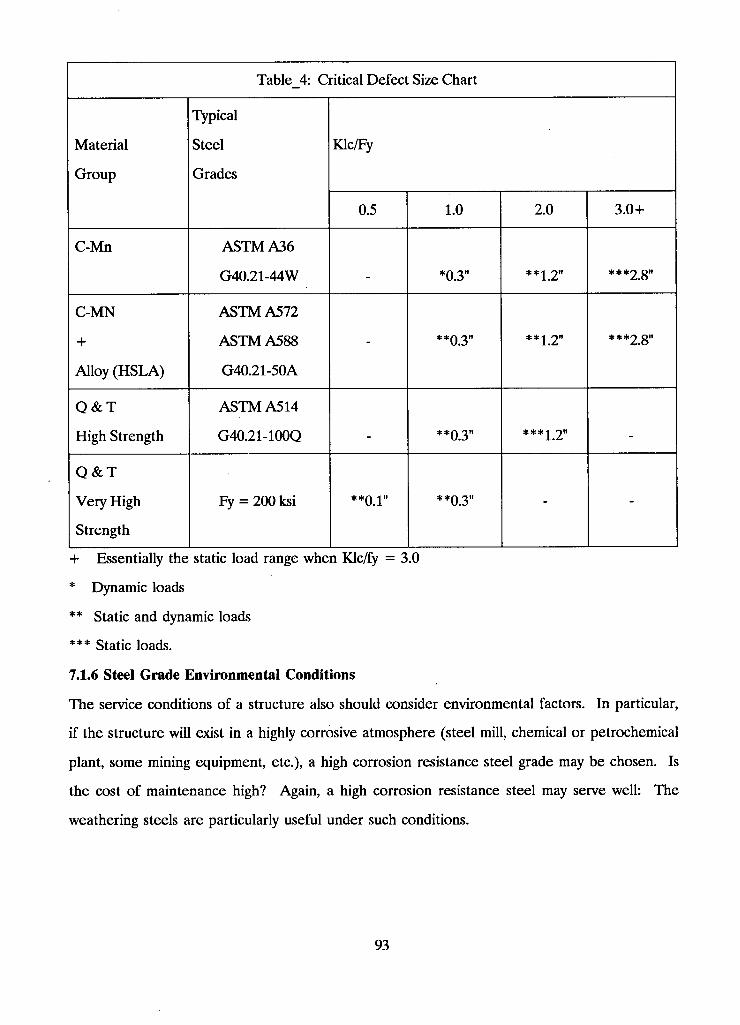
Table_4: Critical Defect Size Chart
Material
Group
Typical
Steel
Grades
Klc/Fy Material
Group
Typical
Steel
Grades
0.5 1.0 2.0 3.0+
C-Mn A S T M A36
G40.21-44W *0.3" **j 2" ***2 8"
C-MN
+
Alloy (HSLA)
A S T M A572
A S T M A588
G40.21-50A
- **0.3" **2 2" ***2.8"
Q & T
High Strength
A S T M A514
G40.21-100Q _ **0.3" _
Q & T
Very High
Strength
Fy = 200 ksi **0 1" **0.3" - -
+ Essentially the static load range when Klc/fy = 3.0
* Dynamic loads
** Static and dynamic loads
*** Static loads.
7.1.6 Steel Grade Environmental Conditions
The service conditions of a structure also should consider environmental factors. In particular,
if the structure will exist in a highly corrosive atmosphere (steel mill, chemical or petrochemical
plant, some mining equipment, etc.), a high corrosion resistance steel grade may be chosen. Is
the cost of maintenance high? Again, a high corrosion resistance steel may serve well: The
weathering steels are particularly useful under such conditions.
93
Will the structure serve under particularly elevated temperatures (certain steel mill operations,
cement factories, etc.), or will a potential fire be especially serious? Both of these criteria have
an impact on the strength and ductility of the material, as well as long-term metallurgical effects.
It is advisable to contact a metallurgist when such factors are considered.
7.2 Design Considerations for Improved Service Behavior
This section of the hyper-text system covers some of the basic in service considerations as they
relate to the design stage.
@1 [7.2.1 Design - Service Conditions] briefly covers potential in service problems
@1 [7.2.2 Improvement of Service Conditions] discusses points to consider at the design stage.
@1 [7.2.3 Weld Strength Computations] covers the basics of proper consideration of weld strength.
7.2.1 Design - Service Conditions
Structure design under static loading presents relatively minor problems, however service tem
peratures may be important. What might be considered a static load at 20 degrees C may not
be treated as such at -20 degrees C.
The design of dynamically loaded structures must incorporate the fatigue characteristics of both
the material and the structure.
For service conditions it is important to note the relative influence of weld defects. Weld defects
influence fatigue life in the following descending order of severity:
(1) Weld cracks
(2) Undercut
(3) Lack of fusion; poor fit-up
(4) Lack of penetration
(5) Slag inclusions
(6) Porosity
Structural strength generally remains relatively unaffected, until the fatigue crack has grown to
substantial proportions (recall the critical defect size chart under [steel grade service conditions]).
However, by this stage the crack may be growing very rapidly, thus becoming a serious strength
and integrity problem for the structure.
94
Lamellar tears are much more serious for fatigue loading than for static loading. However, the
joint and member should always be analyzed to determine stress and strain conditions in the
vicinity of the tear.
Base metal laminations may be analyzed as a lamellar tears where structural strength and integrity
are concerned.
7.2.2 Improvement of Service Conditions
The following points should be considered when selecting a material:
(1) Higher fracture toughness leads to some improvement in fatigue life.
(2) Higher fracture toughness leads to clear improvement for fracture conditions.
(3) Semi or fully killed steel reduces susceptibility to lamellar tearing, but is generally not sufficient
to guarantee no lamellar tearing.
Structural service conditions may be improved if the following fabrication and welding process
considerations are made:
(1) Better quality control leads to a reduction of the size of flaw that is detected. Hence, fatigue
life is increased.
(2) Choice of appropriate welding technique for the job at hand will improve quality.
(3) Careful control of pre-heat, interpass, and post-heat conditions will reduce the risk of
obtaining unsatisfactory welds.
(4) Pre-qualified joints do not guarantee that the weld will be flawless. It only means that the
welder will be able to make the weld properly.
(5) The proper sequence of weld passes, and of different welds in the assembly, is a significant
factor in achieving an improved product.
In the design stage it is important to note that improved service behavior is not only a function
of stress, but also of stress range. Both deserve ample consideration because the former influences
fracture conditions and the latter controls fatigue behavior. The following criteria should be
incorporated into the structural evaluation:
(a) Lower stress improves fracture behavior.
(b) Lower stress range improves fatigue behavior.
(c) Static service load is not normally sufficient to propagate a crack.
95
(d) Joint geometry that produces a condition of high restraint (to weld metal contraction) should
be avoided. It is therefore important to obey the following rules:
(1) Do not overmatch weld metal and base metal.
(2) Do not use intermittent (stitch) welds in a dynamically loaded structure.
(3) Avoid intersecting welds.
(4) Use stiffeners only if the analysis indicates that they are needed.
(5) Specify an erection or construction procedure, if such can be instrumental in reducing high
restraint conditions for welds.
(6) Orient welds such that contraction strains are imposed on the base metal in a longitudinal
direction.
(7) Be aware of service conditions for the structure. Localized effects that have little or no
importance in the structural design may produce fatigue cracks. (Example: Flexible web of a
bridge girder to which a transverse beam has been attached.)
(e) A lamellar tear develops when weld metal contraction is restrained. Service loads will not
produce such tears.
7.23 Weld Strength Computations
The behavior of different types of welds under load can be just as important to the design stage
as weld stresses and capacities. Cost will also play an important role at this level, since some
weld types are clearly more costly than others and the selection of a particular weld profile will
influence the layout of a joint. For example, partial or full penetration welds are expensive.
Although these welds are sometimes necessary to develop the full capacity of the base material,
such as full-strength flange splices of a plate girder, there are many applications where these
costly welds are simply not needed. As an example, it is noted that some designers prefer to call
for full penetration welds between bearing stiffeners and the girder to which they are attached.
Fillet welds would serve this purpose at least as well.
Weld orientation can also be important. The required strength of a fillet weld is obtained whether
the weld is placed parallel or perpendicular to the primary load direction. Its behavior, on the
other hand, it much improved when the weld axis parallels that of the load. In particular, the
ductility of such a welded joint is significantly enhanced. Note that although it is generally agreed
96
that fillet welds are 30 to 40 percent stronger when loaded in the transverse direction, the gov
erning codes do not recognize this increase in strength. This may be partly attributed to the fact
that with increased strength generally comes decreased ductility. As a general rule, therefore, it
is normally preferable that the axis of a weld be oriented parallel to the main direction of force.
This also provides for a better force transfer in the connection.
Strength of Butt Welds
Assuming matching conditions, the strength of butt welds is relatively easy to determine. Whether
the weld is of the full or partial penetration type, if the joint is loaded in compression perpen
dicular to the effective throat, the strength is based on that of the base metal. That is, in no
instance can the welded joint be ascribed a strength higher than the connected base metal.
Full penetration welds loaded with tension normal to the effective throat are also limited in
strength to that of the base metal. The strength of partial joint penetration groove welds,
however, is governed by the smaller of the weld metal and base metal capacity. This is similar
to the governing criterion for design for shear. Certain restrictions apply to the use of partial
joint penetration groove welds in a dynamically loaded structure.
A special note must be made with regard to butt welds subjected to tension or compression
parallel to the weld axis. It is implied that no load transfer takes place across the weld; the joint
simply acts to hold two components together to make them act as a unit. In this case the weld
strength is governed by that of the base metal. Any force transferred across the tension or
compression loaded weld will be carried by shear.
The factored shear strength of a butt weld is computed as the smallest of:
(a) Base metal strength:
Vr = 0.67 [phi] Am Fy (1)
and
(b) Weld metal strength:
Vr = 0.67 [phiw] Aw Xu (2)
A l l of the variables are defined in @1[W_11.3 Design Provisions] for statically loaded structures
or in @1[W_12.3 Design Provisions] for dynamically loaded structures.
97
Equation (1) depicts the strength of the fusion or interface between weld metal and base metal,
[phi] = 0.9 is the performance factor for the base metal. The constant of 0.67 in Eq. (1) represents
the multiplier that transforms tensile yield strength into shear yield strength, thus:
Shear yield strength = (tensile yield strength) / sqrt(3) = 0.57 Fy
It is further increased by approximately 10%, to 0.67 Fy, to account for strain hardening and
other material factors.
Equation (2) depicts the shear strength of the weld metal itself, [phiw] = 0.67 is the performance
factor for the weld metal.
It is seen that since Aw = Am for butt welds, the governing equation of (1) and (2) can be
found by determining the smaller of 0.60 Fy and 0.45 Xu.
The constant in Equation (2) accounts for the relationship between the ultimate tensile and shear
"yield" strengths of the weld metal, as well as a modifier that is incorporated to ensure that the
weld will not fail before the member itself.
Strength of Fillet Welds
The strength of fillet welds loaded in tension parallel to their longitudinal axis is controlled by
the base metal strength. However, no load is to be transferred across the weld itself. If the weld
has to transmit load, it will be carried in shear.
The shear strength of a fillet weld is governed by the smaller of the capacities computed from
Equations (1) and (2). However, the definitions of fusion area and effective area of a fillet weld
are different from those of a butt weld. Refer to @1[W_11.3 Design Provisions] and @1[W_12:3
Design Provisions].
The capacity of the fusion face is governed by the shear yield strength of the base metal, including
an allowance for strain hardening and local plastification.
The weld metal shear strength of a fillet weld is governed by Equation (2), but where the effective
throat area, Aw, is governed by the root measure of the weld. With a fillet weld leg length of
a, the root measure is traditionally computed as
a(root) = a cos45 = 0.707 a (3)
Naturally, this assumes that the weld has been placed correctly, with equal leg length on both
faces, and no concavity of the weld surface.
98
It should be noted that Equation (3) gives the root measure of a manually placed fillet weld
(SMAW, e.g.). For automatic welding such as submerged arc (SAW), using {0.707 a} will be
conservative, since the depth of penetration of an automatic process is significantly larger than
a manual weld. This increase in penetration is acknowledged in @1[W_4.3.2 Fillet Welds].
7.3 Detailing to Achieve Practical Welded Fabrication
Few designers or fabricators are completely up-to-date on modern welding technology or welded
structural design. As a result, many of the errors made by engineers today are caused by a lack
of awareness of state-of-the-art design principles and technological advances. An important point
of concern with regard to the above is: "Anything done five years ago in welding design or
fabrication could be obsolete" [Blodgettl980]. Therefore, any welded detail should be re
evaluated to determine:
(1) if it incorporates new knowledge about how to handle forces;
(2) if it takes advantage of new provisions in governing codes;
(3) if it is compatible with new advances in welding equipment, electrodes, processes, and pro
cedures; and
(4) if it offers opportunity to minimize costs through the use of more precise determinations
made possible by new and more powerful software.
Many weld failures over the years have been the result of certain oversights. The following design
principle violations describe, with example, the results of these oversights:
@1 [07.3.01 Failure to provide a path for transverse force] to enter parts of the member or section
that lies parallel to it.
@1 [07.3.02 Failure to provide a component when a force changes direction]
@1 [07.3.03 Failure to recognize a major force resulting from a load]
@1 [07.3.04 Failure to alter detailing when welding replaces riveting]
@1 [07.3.05 Failure to recognize strain compatibility]
@1 [07.3.06 There are no secondary members in welded design]
@1 [07.3.07 Do not rely on welder skill in place of proper design] to provide strength and per
formance of the weldment.
@1 [07.3.08 Do not place welds in regions of bending]
99
@1 [07.3.09 Failure by compressive fatigue load] in a region containing residual tensile stress.
@1[07.3.10 Failure to design against lamellar tearing]
@1 [07.3.11 Redundancy with diagonal stiffeners] can be costly and unnecessary.
@1 [07.3.12 Failure to consider not-in-service loads]
@1 [07.3.13 Failure to understand matching electrode conditions]
73.1 Failure to Provide a Path for Transverse Forces
Example 1:
Three figures, linked to in the text below, help to illustrate a very simplistic principle. In order
to transfer a force into the load carrying portion of a member or structure, a suitable path must
be provided. @1 [detaill.pcx] shows a lug welded onto the bottom flange, in line with the web,
to transfer the load into the web. @l[detail2.pcx], on the other hand, has the lug mounted
perpendicular to the web and therefore web stiffeners are needed to transfer the load into the
web. Without the stiffeners, an applied load would result in an uneven distribution of stresses
in the weld because of the more flexible flange. Note that the stiffeners are not welded to the
top flange. Finally, @1 [detail3.pcx] shows a lug welded onto the flanges which, in this instance,
are the load carrying sections. The lug is not welded to the web here because that would serve
no purpose in transferring the force. While it seems so elementary it is hardly worthy of mention,
failure to provide such a path possibly leads to more structural design problems than any other
cause.
Further examples of force transfer show lugs welded to box sections. @1 [detail4.pcx] shows an
internal diaphram which, of course, is only realistic for welded box sections. The diaphram would
be welded in before welding on the top plate. @1 [detail5.pcx] illustrates a lug shaped like a sling
and welded directly to the sides of the box section. Note that the lug is not welded to the bottom
flange of the box. In @1 [detail6.pcx], the lug is designed to transfer the force directly into the
two webs from below. This method is very efficient.
Two methods of attaching lugs to circular members are illustrated here. @1 [detail7.pcx] dem
onstrates how a sling shaped lug might be attached to a circular tube. The lug is welded onto
the tub in the area most parallel to the force, the two side quadrants of the circular section.
100
Theory suggests that these two side quadrants carry 82 percent of the shear capacity of the tube.
As a note of interest, the top and bottom quadrants are expected to carry 82 percent of the
moment capacity. [detail8] illustrates an alternative lug that is somewhat simpler to fabricate.
Example 2:
@1 [detail9.pcx] and @l[detaill0.pcx] show an actual problem that resulted from welding an
attachment to the center sill of a piggyback railroad car. Unfortunately, because the designer
overlooked the necessity of providing a proper path for the transfer of forces, cracks developed
in the web. This example applies directly to attachments on structural box girders.
The attachment here is a bracket, or two, used to carry a 500-pound air compressor unit. Note
that there are no interior diaphragms. The vertical force from the weight of the tank is transferred
as moment into the bracket, creating out-of-plane bending at the web. As illustrated, there are
no ready pathways to transfer the horizontal bending forces into the flanges of the open box
section. As a result, the flexible web soon developed fatigue cracks, @ 1 [detaill0.pcx].
Two possible means are suggested for correcting the faulty design. One solution, @1 [de
tain l.pcx], is to shape the bracket so that it runs the full height of the web and can therefore
be welded directly to the center sill flanges. Alternatively, @l[detaill2.pcx], an internal diaphragm
could be welded into the assembly thereby stiffening the flexible web where necessary. The
diaphragm is welded to both flanges and to the web in question. There are now paths for the
bending forces to get to the flanges.
Example 3:
@l[detaill3.pcx] illustrates a floor beam framing into a main girder on a railroad bridge. A
bracket is welded to the top of the floor beam and bolted to the transverse stiffener of the girder.
The forces should eventually end up in the girder flanges but there are no suitable paths because
the stiffener is not welded to the flanges of the girder. The tensile force is taken by the bracket,
and then by the stiffener, after which only the web of the girder can provide reaction. The
out-of-plane bending force on the web is too great, and it cracks under fatigue loading.
7-3.2 Failure to Provide a Component When a Force Changes Direction
Another important consideration occasionally overlooked by structural designers is the need to
provide a component when a force changes direction.
101
Examplel:
@1 [detaill4.pcx] shows a knee, such as is used in building frames, with no provision made for
the component force, Fc. In this instance, the component force is high at the web and low,
almost zero, at the outer edge of the flange thereby producing an uneven distribution of force
in the flange. The limitation here on the component force (ie. only carried by the web) also
limits the flange force thereby limiting the capacity of the overall connection. Now consider
@1 [detaill5.pcx]. The diagonal stiffener provides the necessary component force to handle the
change in direction of the top and bottom flange forces. The forces are transmitted and balanced
through the welds joining the diagonal to the flanges. The diagonal does not have to be welded
to the web for the transfer of forces, however, if there is a concern about buckling, the stiffener
should be designed as a column with appropriately spaced intermittent welds. Additionally, if
the knee is exposed, such as in a bridge, a continuous seal weld might be needed to keep out
water. Note that the size of the force balloon in each figure gives an indication of the capacity
of the knee.
Example 2:
This example illustrates how a crack developed in a part of a structural frame for a cantilevered
balcony. Unfortunately, during fabrication of the girder, no thought was given to the component
force and no stiffener was specified. To compound the error, when the welder placed the
intermittent welds, it just happened that no weld was placed at the point of change in direction
of the flange. The top of @l[detaill6.pcx] illustrates the problem portion of the frame. From
observation, we can see how large tensile forces might be introduced into the web during service
conditions and how, subsequently, a crack might soon develop. The bottom of [detail 16] shows
how brackets should have been welded on where the flange changes direction and component
forces are developed.
Example 3:
Structural designers should always be aware of the different requirements for curved sections
subject to moments.
102
The large radius of flange curvature in the structural knee of @l[detaill7.pcx] will transfer much
smaller forces into the flange-to-web weld than the small radius of flange curvature in the
mechanical press of @l[detaill8.pcx]. In the structural knee, the unit radial forces, which are
developed from the curvature, are compressive and therefore push the inner flange against the
web. The welds attaching the inner flange to the web transfer little or no force at all; they merely
hold the parts together. On the other hand, the unit radial forces in the mechanical press are
relatively high because of the lesser radius of curvature, and are in the opposite direction. With
the inner flange now in tension rather than compression, the flange-to-web weld must now bear
the full radial force throughout the length of curvature. Occasionally these welds break because
they are undersized.
Three methods of handling component forces in a press frame are shown in @1 [detaill9.pcx].
In all three illustrations, the inner flange develops component forces that must be dealt with.
The press frame on the left of the figure uses a diagonal to accomplish this while the middle
frame and the one on the right use diaphrams.
Example 4:
@1 [detail29.pcx] shows a portion of an arm used on large concrete hauling trucks to carry a third
axle which was put down when the truck was loaded. This example illustrates an actual problem
that occurred as a result of transferring radial force.
The arm was made from 1/4 inch plate and welded with 1/4 inch fillets. Under service conditions,
cracks were discovered in the fillet welds. Further analysis demonstrated that the applied bending
moment was subjecting the inner flange to tension. This axial tension was generating a radial
force directed toward the center of curvature of the arm. This radial force, acting across the
width of the flange, was only resisted by the two webs. Therefore, the flange went into curvature
and imposed bending moments on the web-to-flange fillet welds. These bending moments put
the root of the fillet weld into tension which subsequently caused the weld to crack.
One solution to the problem was to place a second fillet weld along the inside of the web-to-flange
connection for the full length of the arc and past the point of tangency. The induced bending
would then put the face of the inside fillet weld into tension which is quite acceptable for rea
sonable loads. This, of course, means that the top flange would have to be welded last.
103
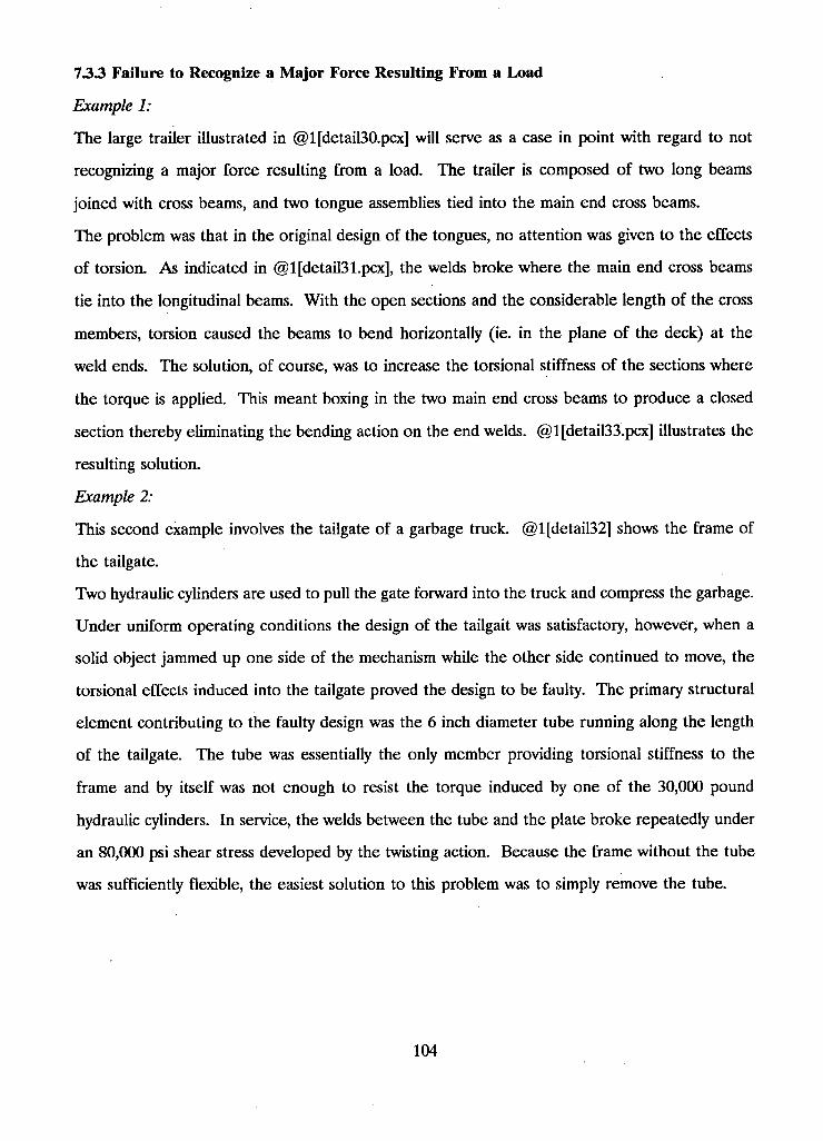
7.3.3 Failure to Recognize a Major Force Resulting From a Load
Example 1:
The large trailer illustrated in @1 [detail30.pcx] will serve as a case in point with regard to not
recognizing a major force resulting from a load. The trailer is composed of two long beams
joined with cross beams, and two tongue assemblies tied into the main end cross beams.
The problem was that in the original design of the tongues, no attention was given to the effects
of torsion. As indicated in @l[detail31.pcx], the welds broke where the main end cross beams
tie into the longitudinal beams. With the open sections and the considerable length of the cross
members, torsion caused the beams to bend horizontally (ie. in the plane of the deck) at the
weld ends. The solution, of course, was to increase the torsional stiffness of the sections where
the torque is applied. This meant boxing in the two main end cross beams to produce a closed
section thereby eliminating the bending action on the end welds. @1 [detail33.pcx] illustrates the
resulting solution.
Example 2:
This second example involves the tailgate of a garbage truck. @l[detail32] shows the frame of
the tailgate.
Two hydraulic cylinders are used to pull the gate forward into the truck and compress the garbage.
Under uniform operating conditions the design of the tailgait was satisfactory, however, when a
solid object jammed up one side of the mechanism while the other side continued to move, the
torsional effects induced into the tailgate proved the design to be faulty. The primary structural
element contributing to the faulty design was the 6 inch diameter tube running along the length
of the tailgate. The tube was essentially the only member providing torsional stiffness to the
frame and by itself was not enough to resist the torque induced by one of the 30,000 pound
hydraulic cylinders. In service, the welds between the tube and the plate broke repeatedly under
an 80,000 psi shear stress developed by the twisting action. Because the frame without the tube
was sufficiently flexible, the easiest solution to this problem was to simply remove the tube.
104
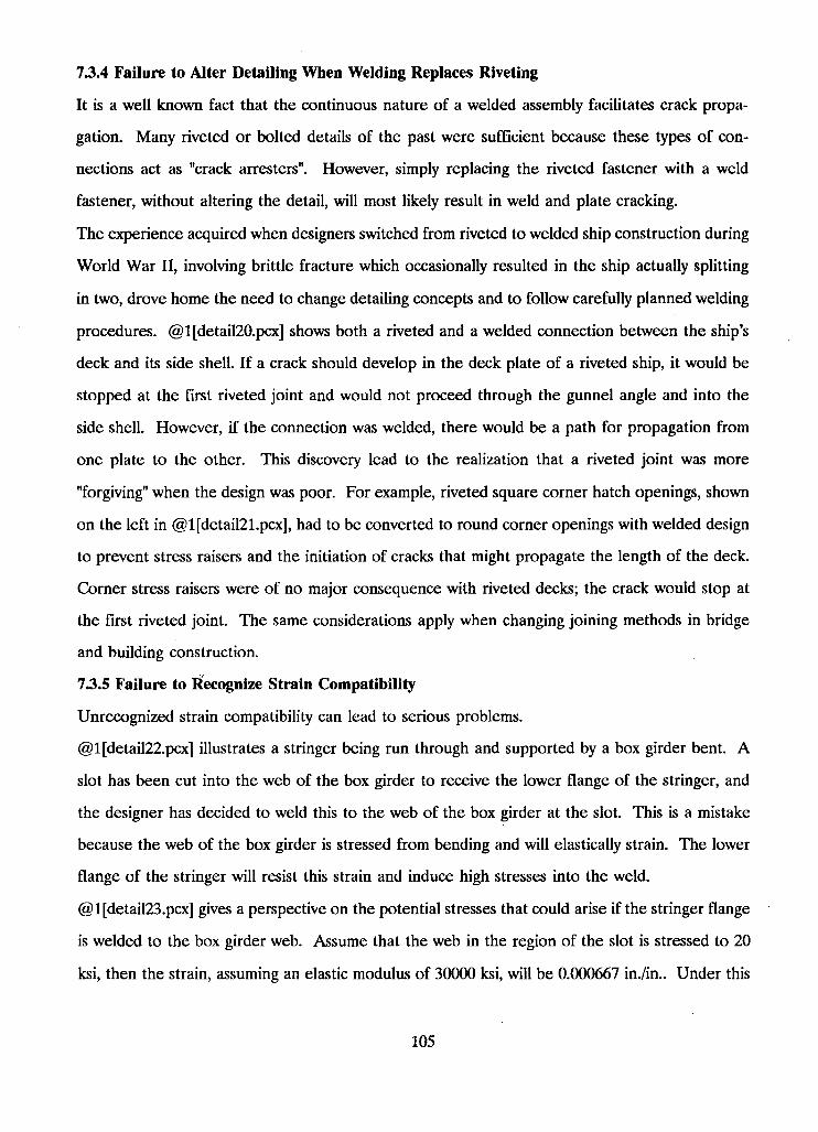
73.4 Failure to Alter Detailing When Welding Replaces Riveting
It is a well known fact that the continuous nature of a welded assembly facilitates crack propa
gation. Many riveted or bolted details of the past were sufficient because these types of con
nections act as "crack arresters". However, simply replacing the riveted fastener with a weld
fastener, without altering the detail, will most likely result in weld and plate cracking.
The experience acquired when designers switched from riveted to welded ship construction during
World War II, involving brittle fracture which occasionally resulted in the ship actually splitting
in two, drove home the need to change detailing concepts and to follow carefully planned welding
procedures. @1 [detail20.pcx] shows both a riveted and a welded connection between the ship's
deck and its side shell. If a crack should develop in the deck plate of a riveted ship, it would be
stopped at the first riveted joint and would not proceed through the gunnel angle and into the
side shell. However, if the connection was welded, there would be a path for propagation from
one plate to the other. This discovery lead to the realization that a riveted joint was more
"forgiving" when the design was poor. For example, riveted square corner hatch openings, shown
on the left in @l[detail21.pcx], had to be converted to round corner openings with welded design
to prevent stress raisers and the initiation of cracks that might propagate the length of the deck.
Corner stress raisers were of no major consequence with riveted decks; the crack would stop at
the first riveted joint. The same considerations apply when changing joining methods in bridge
and building construction.
73.5 Failure to Recognize Strain Compatibility
Unrecognized strain compatibility can lead to serious problems.
@1 [detail22.pcx] illustrates a stringer being run through and supported by a box girder bent. A
slot has been cut into the web of the box girder to receive the lower flange of the stringer, and
the designer has decided to weld this to the web of the box girder at the slot. This is a mistake
because the web of the box girder is stressed from bending and will elastically strain. The lower
flange of the stringer will resist this strain and induce high stresses into the weld.
@1 [detail23.pcx] gives a perspective on the potential stresses that could arise if the stringer flange
is welded to the box girder web. Assume that the web in the region of the slot is stressed to 20
ksi, then the strain, assuming an elastic modulus of 30000 ksi, will be 0.000667 in./in.. Under this
105
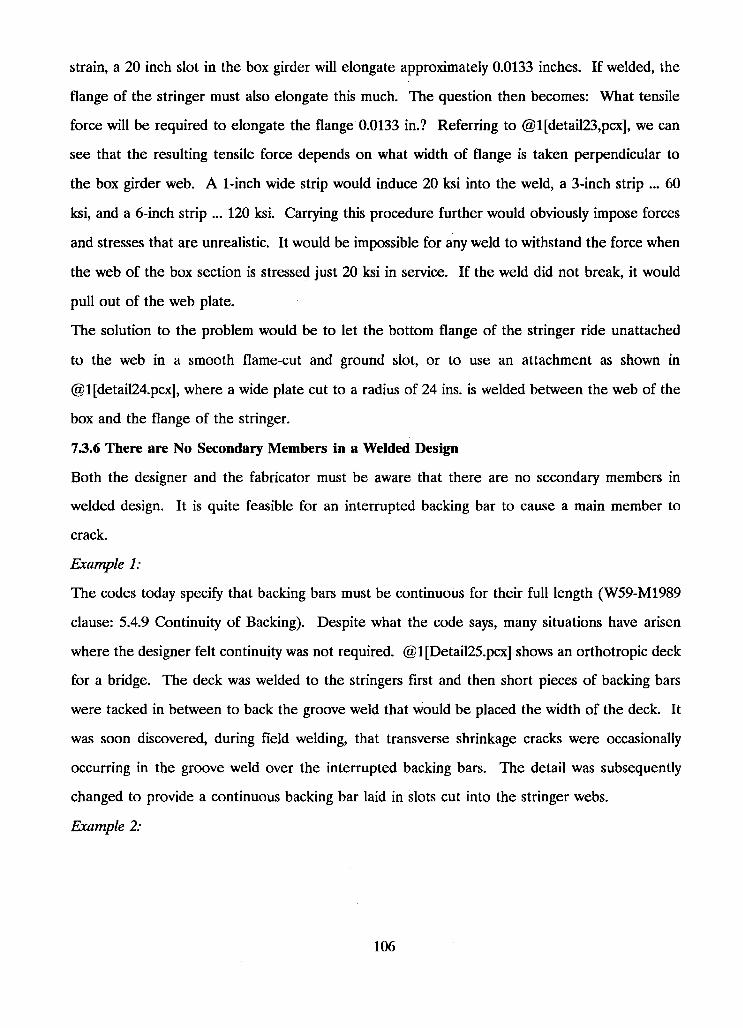
strain, a 20 inch slot in the box girder will elongate approximately 0.0133 inches. If welded, the
flange of the stringer must also elongate this much. The question then becomes: What tensile
force will be required to elongate the flange 0.0133 in.? Referring to @l[detail23,pcx], we can
see that the resulting tensile force depends on what width of flange is taken perpendicular to
the box girder web. A 1-inch wide strip would induce 20 ksi into the weld, a 3-inch strip ... 60
ksi, and a 6-inch strip ... 120 ksi. Carrying this procedure further would obviously impose forces
and stresses that are unrealistic. It would be impossible for any weld to withstand the force when
the web of the box section is stressed just 20 ksi in service. If the weld did not break, it would
pull out of the web plate.
The solution to the problem would be to let the bottom flange of the stringer ride unattached
to the web in a smooth flame-cut and ground slot, or to use an attachment as shown in
@1 [detail24.pcx], where a wide plate cut to a radius of 24 ins. is welded between the web of the
box and the flange of the stringer.
73.6 There are No Secondary Members in a Welded Design
Both the designer and the fabricator must be aware that there are no secondary members in
welded design. It is quite feasible for an interrupted backing bar to cause a main member to
crack.
Example 1:
The codes today specify that backing bars must be continuous for their full length (W59-M1989
clause: 5.4.9 Continuity of Backing). Despite what the code says, many situations have arisen
where the designer felt continuity was not required. @1 [Detail25.pcx] shows an orthotropic deck
for a bridge. The deck was welded to the stringers first and then short pieces of backing bars
were tacked in between to back the groove weld that would be placed the width of the deck. It
was soon discovered, during field welding, that transverse shrinkage cracks were occasionally
occurring in the groove weld over the interrupted backing bars. The detail was subsequently
changed to provide a continuous backing bar laid in slots cut into the stringer webs.
Example 2:
106
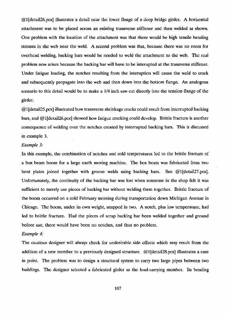
@1 [detail26.pcx] illustrates a detail near the lower flange of a deep bridge girder. A horizontal
attachment was to be placed across an existing transverse stiffener and then welded as shown.
One problem with the location of the attachment was that there would be high tensile bending
stresses in the web near the weld. A second problem was that, because there was no room for
overhead welding, backing bars would be needed to weld the attachment to the web. The real
problem now arises because the backing bar will have to be interupted at the transverse stiffener.
Under fatigue loading, the notches resulting from the interuption will cause the weld to crack
and subsequently propagate into the web and then down into the bottom flange. An analogous
scenario to this detail would be to make a 1/4 inch saw cut directly into the tension flange of the
girder.
@ lfdetail25.pcx] illustrated how transverse shrinkage cracks could result from interrupted backing
bars, and @1 [detail26.pcx] showed how fatigue cracking could develop. Brittle fracture is another
consequence of welding over the notches created by interrupted backing bars. This is discussed
in example 3.
Example 3:
In this example, the combination of notches and cold temperatures led to the brittle fracture of
a box beam boom for a large earth moving machine. The box beam was fabricated from two
bent plates joined together with groove welds using backing bars. See @ 1 [detail27.pcx].
Unfortunately, the continuity of the backing bar was lost when someone in the shop felt it was
sufficient to merely use pieces of backing bar without welding them together. Brittle fracture of
the boom occurred on a cold February morning during transportation down Michigan Avenue in
Chicago. The boom, under its own weight, snapped in two. A notch, plus low temperature, had
led to brittle fracture. Had the pieces of scrap backing bar been welded together and ground
before use, there would have been no notches, and thus no problem.
Example 4:
The cautious designer will always check for undesirable side effects which may result from the
addition of a new member to a previously designed structure. @ lfdetail28.pcx] illustrates a case
in point. The problem was to design a structural system to carry two large pipes between two
buildings. The designer selected a fabricated girder as the load-carrying member. Its bending
107
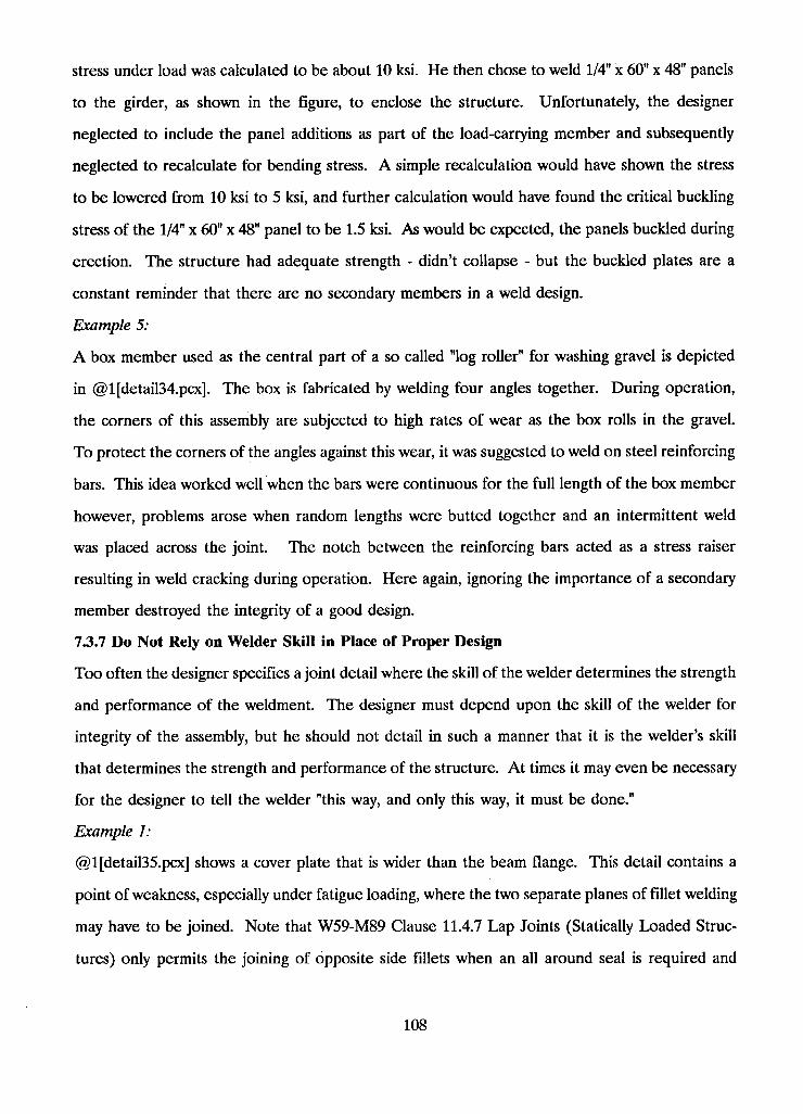
stress under load was calculated to be about 10 ksi. He then chose to weld 1/4" x 60" x 48" panels
to the girder, as shown in the figure, to enclose the structure. Unfortunately, the designer
neglected to include the panel additions as part of the load-carrying member and subsequently
neglected to recalculate for bending stress. A simple recalculation would have shown the stress
to be lowered from 10 ksi to 5 ksi, and further calculation would have found the critical buckling
stress of the 1/4" x 60" x 48" panel to be 1.5 ksi. As would be expected, the panels buckled during
erection. The structure had adequate strength - didn't collapse - but the buckled plates are a
constant reminder that there are no secondary members in a weld design.
Example 5:
A box member used as the central part of a so called "log roller" for washing gravel is depicted
in @1 [detail34.pcx]. The box is fabricated by welding four angles together. During operation,
the corners of this assembly are subjected to high rates of wear as the box rolls in the gravel.
To protect the corners of the angles against this wear, it was suggested to weld on steel reinforcing
bars. This idea worked well when the bars were continuous for the full length of the box member
however, problems arose when random lengths were butted together and an intermittent weld
was placed across the joint. The notch between the reinforcing bars acted as a stress raiser
resulting in weld cracking during operation. Here again, ignoring the importance of a secondary
member destroyed the integrity of a good design.
73.7 Do Not Rely on Welder Skill in Place of Proper Design
Too often the designer specifies a joint detail where the skill of the welder determines the strength
and performance of the weldment. The designer must depend upon the skill of the welder for
integrity of the assembly, but he should not detail in such a manner that it is the welder's skill
that determines the strength and performance of the structure. At times it may even be necessary
for the designer to tell the welder "this way, and only this way, it must be done."
Example 1:
@1 [detail35.pcx] shows a cover plate that is wider than the beam flange. This detail contains a
point of weakness, especially under fatigue loading, where the two separate planes of fillet welding
may have to be joined. Note that W59-M89 Clause 11.4.7 Lap Joints (Statically Loaded Struc
tures) only permits the joining of opposite side fillets when an all around seal is required and
108
Clause 12.4.7 Lap Joints (Dynamically Loaded Structures) does not permit the joining at all. This
point of weakness demands the welder to properly join the longitudinal and transverse fillets.
The problems that would arise as a result of producing a crater, concave end, or notch at the
point of weakness are far too important to be gambling on such a detail. Instead, the detail in
@ l[detail36.pcx] should be used where the cover plate is narrower than the flange and the fillet
weld is continuous in one plane. This detail will help to eliminate the question of welder per
formance.
Example 2:
@1 [detail37.pcx] illustrates a gearbox used in mining machinery. You can see many points of
weakness where welds on opposite sides of a plane are tied together. The assembly did not last
long in service before it began to break up. Many of the points of weakness have been eliminated
in the preferred detail shown in @1 [detail38.pcx].
Example 3:
@1 [detail47.pcx] illustrates a detail which leaves much to the welder. @ 1 [detail48.pcx] is a
substantial improvement in detail because the performance of the structure does not hinge on
the knowledge, skill, and convenience of the welder.
The detail is the support bracket for a short beam section. A two-span continuous plate girder
cantilevers out beyond a pier to support the short suspended beam. The bracket will be loaded
in bending with its top outer fibre in tension. The outer fibre in @1 [detail47.pcx] is comprised
of the edge of a flame-cut plate and either the start or stop of the fillet weld. There is an even
chance that the weld will terminate with a crater at the point of high bending stress. Perhaps
of minor importance is that the detail provides no horizontal stiffness for the bracket.
@l[detail48.pcx] requires a little more material and work, but eliminates the chance of design
failure. The outer fibre in bending now becomes the top smooth surface of the flange plate.
There is no flame-cut edge of a plate or weld crater to affect performance and there is good
horizontal stiffness for the bracket.
73.8 Do Not Place Welds in Regions of Bending
Example 1:
109
Placing welds in regions of bending is another mistake often made by designers. @1 [detail39.pcx]
illustrates a case where welds were placed in a region of high bending. Two welded angles were
used to support a hydraulic motor. The motor was fastened into the outstanding legs while the
hold down legs were bolted to the base. An uplift force on the pinion of the motor put the hold
down bolts in tension which, because of the eccentricity, demanded a high moment from the
welded angle corners. With this detail, there was no way of eliminating the moment and the
welds broke in service.
To correct the problem, the detail attaching the motor to its base had to be modified. One
solution was to have the base metal plate run the full length of the motor assembly, as shown in
@1 [detail40.pcx]. Most of the moment developed from the eccentricity of the hold down bolts
is now taken by the base plate. The support welds are now subjected to tensile uplift instead of
bending.
Example 2:
This example makes use of a principle which is well known in the structural field, namely, one
can avoid problems with bending moments by placing welds at points of inflection (ie. zero
bending moment).
The middle of @l[detail41.pcx] illustrates the moment diagram from internal pressure in the
pressure vessel. Welding at the points of inflection would mean placing the welds as shown in
the top of the Figure. This method of fabricating will produce a stronger vessel than one made
with only two welds, seen in the bottom of the figure. If the internal pressure is high, the cost
of twice as much welding may be money well spent.
73.9 Failure by Compressive Fatigue Load
There have been a few rare instances where a designer has inadvertently imposed a compressive
fatigue load onto a region of residual tensile stress. A weld zone will remain in a state of residual
tensile stress providing it has not undergone any form of stress relief. If repeated compressive
loads are then imparted onto this region, it will bounce back and forth between a state of stress
relief and a state of residual tensile stress. If the compressive loads are severe enough, the weld
will eventually break by tensile fatigue.
Example 1:
110
This first example involves a welded, shrink-fitted gear which failed in service because of com
pressive fatigue loading. As illustrated in @l[detail42.pcx], the rim was first shrink-fitted to the
disc and then fillet welded on both sides all the way around the disc. This resulted in very high
tensile residual stresses in the welds.
Unfortunately, during service loading, the rim fell off the disc. Subsequent investigation showed
excessive wear at the root of the teeth which suggested that the meshing gears had been operating
too closely together. This observation led to the cause of, and the solution to, the problem.
During operation, the fillet welds received repeated compressive loading because the gears were
out of alignment. Because these welds were already in a state of tensile residual stress, the
repeated loading induced tensile fatigue and failure eventually occurred at angles of 10 and 20
degrees from the rim. See @l[detail43.pcx]. The angle of the failure plane further reenforces
the theory of tensile fatigue because the maximum tensile stress under transverse loading occurs
on the 22.5 degree plane as opposed to the maximum shear stress which occurs on the 67.5
degree plane. See @l[detail44.pcx]. Furthermore, if the weld had failed as a result of torsion,
the failure plane would be closer to 45 degrees.
The solution to the problem was to eliminate the shrink fitting so as to reduce the locked in
residual stresses in the welds and to ensure proper alignment of the gears.
Example 2:
A frame for a hydraulic lift is shown in [detail45]. Here again compressive loading has caused a
fatigue crack by working against a residual tensile stress. @1 [detail46.pcx] shows more closely
what is actually going on. The failure here occurs as a crack in the plate adjacent to the weld.
73.10 Failure to Design Against Lamellar Tearing
Any reduction in weld metal used usually means a reduction in cost. Additional benefits are a
decrease in weld distortion and a reduction in locked in stresses that might lead to lamellar tearing.
In general, the designer should consider alternative joint designs and use the one which requires
the least amount of weld metal.
I l l
In addition to weld metal reduction, a change in detail may also aid in reducing the probability
of lamellar tearing. @ 1 [detail49.pcx] illustrates how transverse residual stress can act on an
inclusion to create a lamellar tear. The tendency for lamellar tearing is reduced in @l[de-
tail50.pcx] by skewing the critical section and passing the weld through many lines of inclusion.
Example:
@ lfdetail51.pcx] illustrates a detail that was originally included in the plans for the construction
of a stadium. The cantilevered beam was to be welded to a column where stiffeners were required.
Design consultants on the job felt the detail lacked any sort of safeguard against lamellar tearing,
which had been encountered recently in other welded structures. Should striations exist in the
rolled plate forming the flange of the column and, further, should they pull apart, there would
be nothing to prevent the beam and column from separating, and no other means to avoid
collapse.
@l[detail52.pcx] illustrates the preferred detail that was recommended and used in the con
struction of the stadium. Note that the possibility of lamellar tearing at the tension region has
been virtually eliminated. Although the bottom flange of the beam is still welded to the outside
of the column plate, lamellar tearing should not be a problem because the bottom flange is in
compression.
73.11 Redundancy With Diagonal Stiffeners
Redundancy serves no useful purpose in a well designed ground structure. The addition of
unnecessary parts merely runs up costs and may actually weaken the member. In certain instances,
"just to be safe", a designer may place double diagonal stiffeners in the column framing of a
building. This suggests that the designer was uncertain about the performance of diagonals.
@ lfDetail54.pcx] and @1 [Detail55.pcx] show two ways to use diagonal stiffeners in transferring
a moment from a beam into a column. The former sketch shows the diagonal in compression
while the latter shows it in tension. Each method of placement transfers the moment effectively.
Of the two details, welding is less critical when the welds transfer compression.
The fitting and welding of a double diagonal brace greatly increases the connection cost. If the
designer felt that one diagonal was inadequate for the moment, the logical step would have been
112
merely to increase the thickness of that single diagonal. Note that in welding diagonals it is only
necessary to weld where force enters and leaves the diagonal, although a small weld may be used
at the centre of a compression diagonal if there is concern about buckling.
73.12 Failure to Consider Not-in-Service Loads
What happens to a structural member before it is put into use can affect its design. The designer
should be aware that all members are subjected to handling, loading, shipping, unloading, and
erection operations. As an example, the deep plate girder, shown in @1 [Detail53.pcx], was
shipped to the site tied down to a flat-bed railroad car. An inspection of the girder after shipment
uncovered cracks in the web near the lower end of the transverse stiffener. It was generally
agreed that the cracking was the result of fatigue.
Repeated displacement of the top flange relative to the bottom resulted during shipment. These
lateral displacements resulted from the many thousands of jolts encountered during transit. This
action demanded high flexibility from the one-inch unstiffened portion of the web between the
flange and the stiffener. Unfortunately, the cyclical bending stresses were too much for such a
small section of the web and fatigue cracks developed. It was later recommended that the stiffener
should stop back at least four to six times the web thickness from the tension flange to spread
the flexing over a larger area.
73.13 Failure to Understand Matching Electrode Conditions
Although the following example refers to American codes, the Canadian codes are similar in
nature and so the principle concept remains valid.
The designer or fabricator should be familiar with prevailing codes, and especially any recent
changes that simplify design or fabrication tasks. A shop was fabricating a girder from A572
grade 65 steel. Table 4.1.1 of the AWS D l . l Structural Welding Code indicated that the matching
weld metal would be from an E80 electrode wire for either gas metal arc or flux-cored arc welding
meeting this strength level. But an E80 electrode was not really required. Because the girder
was to be fillet welded, the very common and abundant E70 weld metal was all that was required.
Not only did E70 metal fully meet codes, but it would also reduce the chance for cracking and
other problems. The company had gone wrong by assuming AWS Table 4.1.1 demanded that
matching weld metal be used with the A572 steel. The engineers should have taken a look at
113
Table 8.4.1 for buildings or Table 9.3.1 for bridges. If they had, they would have found that
matching weld metal is required only for complete-penetration groove welds with tension applied
normal to the effective throat. This means that butt welds in the flanges of tension girders would
require matching weld metal - but there were only fillet welds in the subject girder. According
to AWS Table 8.4.1, weld metal with a strength level equal to or less than matching weld metal
could be used. An E70 electrode would meet code specifications.
114
8 Determine Weld Size
Overwelding is one of the major factors determining welding cost. Specifying the correct weld
size is the first step toward obtaining low-cost welding. Therefore, simple methods are necessary
to determine the appropriate volume of weld needed to provide adequate strength for all types
of connections.
The general design provisions for welds in structural steel work are defined in the CSA standard
- W59-M1989. There are "welding electrode - base metal" matching conditions laid out in this
standard which may or may not be mandatory depending on the type of weld and the type and
direction of loading. These matching conditions are intended to ensure structural continuity by
keeping the variation in mechanical properties across the weld zone within tolerable limits.
In the presence of demanding service conditions, the complete joint penetration groove weld is
preferred. Since the groove weld, properly made, has equal or better strength than the thinner
plate joined, there is no need for calculating the resistance of the weld. On the other hand,
depending on the direction and type of load, the size and resistance of a partial joint penetration
groove weld will usually have to be determined. The CSA standard, W59 - M1989, lists many
prequalified complete and partial joint penetration groove welds in order to simplify the design
and fabrication procedure.
Many standardized connections utilize the fillet weld. The determination of correct fillet weld
size is essential to maintaining structural integrity while minimizing distortion.
Plug and slot welds are quite limited in their usefulness in welded structures. They are generally
only used when the use of a groove or fillet weld has been deemed impractical.
8.1 Welding Electrode - Base Metal Matching Conditions
The basic philosophy behind the matching principle is to maintain an ultimate strength of weld
metal (Xu) that is greater than the ultimate tensile strength of the base metal (Fu). However,
to maintain a modicum of material property continuity across the heat affected zone, the matching
electrode is generally stipulated such that Xu is just greater than Fu. As an example, for a base
metal minimum tensile strength of between 400 and 480 MPa, the matching electrode ultimate
strength is 480 Mpa. And for Fu between 480 MPa and 550, Xu is 550 MPa.
115

It should be noted that the yield strength of neither the weld metal nor the base metal has been
considered here. In general, however, the ratio of yield to ultimate tensile strength for the weld
metal will be higher than that of the base metal thereby resulting in a weld yield higher than the
base yield.
Tables 11-1 and 12-1 of W59-M1989 for, respectively, statically and dynamically loaded structures
contain tabulated "matching requirements" for many grades of steel.
8.2 Design of Complete Joint Penetration Groove Welds
Whether designing for allowable stresses or factored resistances, the capacity of the complete
joint penetration groove (CJPG) weld is considered to be at least as good as the base metal,
assuming matching conditions apply.
The W59 standard defines the effective weld area (ie. That section through the weld assumed
effective in transferring stress) as the effective weld length multiplied by the effective throat
thickness. The effective weld length of any groove, square or skewed to the direction of stress,
shall be the width of the part joined. The effective throat thickness is the thickness of the thinnest
part joined.
Transition of thickness or width:
The following transition rules are governed by @1[W59_11.4.8 Transition of Thickness or Width]
for statically loaded structures and by @1[W59_12.4.8 Transition of Thickness or Width] for
dynamically loaded structures. Under static loading the following condition applies.
The transition zone of butt joints composed of plates of unequal width or thickness shall not
incorporate slopes steeper than 4 in 10. Figures @l[W59_1101.pcx], @l[W59_1102.pcx], and
@1 [W59_1103.pcx] illustrate three methods of achieving the 4 in 10 slope in the transition zone
of joints with unmatched thickness. The detail in figure @1 [W59_1104.pcx] shows the transition
through unequal widths.
The W59 Clauses stated above should be viewed for further details and possible exemption from
the above requirement.
116
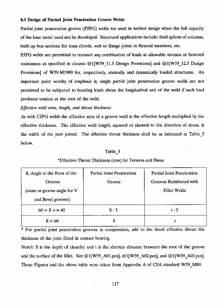
S3 Design of Partial Joint Penetration Groove Welds
Partial joint penetration groove (PJPG) welds are used in welded design when the full capacity
of the base metal need not be developed. Structural applications include: field splices of columns,
built-up box sections for truss chords, web to flange joints in flexural members, etc.
PJPG welds are permitted to transmit any combination of loads at allowable stresses or factored
resistances as specified in clauses @1[W59_11.3 Design Provisions] and @1[W59_12.3 Design
Provisions] of W59-M1989 for, respectively, statically and dynamically loaded structures. An
important point worthy of emphasis is; single partial joint penetration groove welds are not
permitted to be subjected to bending loads about the longitudinal axis of the weld if such load
produces tension at the root of the weld.
Effective weld area, length, and throat thickness:
As with CJPG welds the effective area of a groove weld is the effective length multiplied by the
effective thickness. The effective weld length, squared or skewed to the direction of stress, is
the width of the part joined. The effective throat thickness shall be as indicated in Table_5
below.
Table_5
*Effective Throat Thickness (mm) for Tension and Shear
8, Angle at the Root of the
Groove
(same as groove angle for V
and Bevel grooves)
Partial Joint Penetration
Groves
Partial Joint Penetration
Grooves Reinforced with
Fillet Welds
60 > 6 > = 45 S-3 t -3
B > 60 S t
* For partial joint penetration grooves in compression, add to the listed effective throat the
thickness of the joint fitted in contact bearing.
Notel: S is the depth of chamfer and t is the shortest distance between the root of the groove
and the surface of the fillet. See @l[W59_A01.pcx], @l[W59_A02.pcx], and @l[W59_A03.pcx].
These Figures and the above table were taken from Appendix A of CSA standard W59_M89.
117
Note2: The effective throat thicknesses stipulated in Table A - l above are based on the ease at
which full root penetration may be achieved and they assume a root gap of zero. It should be
stated that greater penetration would be feasible with root openings greater than zero however
the author found no accountability of this in the standard.
Minimum groove depth partial joint penetration groove welds:
Just as fillet welds have a minimum size for thick plates because of fast cooling and greater
restraint, so partial penetration groove welds have a minimum groove depth which should be
used. Refer to @1[W59_4.3.4.1 Partial Joint Penetration Groove Welds] to view Table 4-3
Minimum Groove Depth for Partial Joint Penetration Groove Welds (Not Combined with Fillet
Welds).
Partial joint penetration groove welds in tubular construction:
Partial joint penetration groove welds used in tubular construction may be considered as having
equivalent strength to complete joint penetration groove welds if certain conditions are met.
Appendix L of W59_M89 contains more information on this subject.
Flare groove welds:
As stipulated in W59_M89, all flare groove welds are classified as partial joint penetration groove
welds.
The determination of the effective throat thickness of flare-V and flare-bevel groove welds on
hollow structural sections is the responsibility of the contractor. Unless otherwise approved by
the engineer, the effective throat thickness shall be established by means of trial welds for each
set of procedural conditions. The trial welds shall then be sectioned and measured to establish
welding techniques that will ensure that the design throat thickness is achieved in production.
The effective throats for flare grooves on solid bars are defined in section @1[W59_4.3.1.6.2
Solid Bars] of W59-M89. In most cases of flare groove welds on solid bars no joint preparation
is necessary because of the inherent shape of the bars.
S.4 Design of Fillet Welds
Fillet welds may be continuous or intermittent, although certain restrictions apply with the use
of intermittent fillet welds in dynamically loaded structures. Fillet welds may be used to transmit
any combination of loads at allowable stresses or factored resistances as specified in Clause
118
@1[W59_11.3 Design Provisions] for statically loaded structures or Clause @1[W59_12.3 Design
Provisions] for dynamically loaded structures. Single fillet welds may not transfer bending about
the longitudinal axis of the weld if it produces tension at the root of the weld. Fillet welds may
be used for connecting parts whose respective fusion faces form an angle between 60 and 120
degrees. When the angle between the faces is less than 60 degrees the weld shall be considered
a partial joint penetration groove weld. For angles greater than 120 degrees, the fillet weld may
not be relied upon to transmit calculated load.
The direction of loading has a significant effect on the ultimate strength of a fillet weld.
Transverse fillet welds have been found to be as high as 40 percent stronger than longitudinal
fillet welds. However, this increased strength is not recognized by Canadian structural welding
specifications. Instead, the strength is based on loading in the longitudinal direction irrespective
of the true in service loading angle.
Effective fillet size:
W59_M89 has defined the effective throat area of a fillet weld to be equal to the effective length
of the weld multiplied by the effective throat thickness. The effective length of a fillet weld
incorporates the overall length plus end returns. In other words, if the weld section is full size
throughout its length, no reduction in length is necessary for the start or termination of the weld.
The effective throat thickness is defined as the shortest distance from the root of the diagrammatic
weld to the face for all processes except SAW.
When submerged arc welding (SAW) is used, the effective throat thickness is considered to be
the next larger size fillet, expressed in millimeters, providing the leg sizes are equal and sufficient
penetration has been achieved to justify such an increase. In other words, the penetration must
be deep enough to provide a diagrammetric weld size equal to or greater than the next larger
fillet size. The design drawings will show the theoretical fillet size required and the actual size
shall be not less than the minimum required in Table 4-4 of @1[W59_4.3.4 Minimum size of
Fillet Welds].
Figure @1 [wsizel.pcx] shows the effective cross-sectional area of an equal legged fillet weld in
a right angled corner. The effective size and throat thickness are illustrated in this diagram.
Similarly, @1 [wsize2.pcx] illustrates the unequal legged fillet weld also fused into a right angled
119
corner. Many times fillet welds are placed into joints where the fusion faces form an angle other
than 90 degrees. The following paragraph describes briefly how the CSA standard W59-M89
deals with this scenario.
Although the strength of a fillet weld is determined from the shear capacity of the effective
throat, the Canadian practice is to express weld dimensions in terms of an effective leg size. The
effective size is the leg size of an equivalent fillet between fusion faces at 90 degrees having the
same throat thickness as the measured fillet size under the skewed condition. Figure
@1 [W59_0403.pcx] illustrates the method used to determine the effective fillet weld size from
the measured size and vice versa. This diagram shows the relationship between the effective size
of the fillet weld (E), the measured size of the fillet weld (S), the gap (G), and the angle between
the fusion faces (theta). The measured size (S) of each fillet shall be the smaller of the two leg
sizes and gaps less than 1 mm may be ignored. In addition, the gap size may not exceed 5 mm
on either side of the joint.
Minimum fillet weld size:
In addition to strength, the minimum size of fillet weld is governed by material thickness. The
Canadian Standards Association recognizes that thick plates offer greater restraint, and produce
a faster cooling rate for the welds. Too fast a cooling rate will produce undesirable weld
properties and possibly lead to weld cracking. Table 4-4 of @l[W59_4.3.4b Minimum Length
and Size of Fillet Welds] tabulates the minimum fillet sizes permitted in relation to the thickness
of the thicker part joined. Table 4-4 is predicated on the theory that the required minimum weld
size will provide sufficient welding heat input into the plate to give the desired slow rate of
cooling. Note that the minimum weld size need not exceed the thickness of the thinner part
joined unless required by calculated stress. With regard to this exception, sufficient heat input
must be provided to ensure weld soundness. Also note that Table 4-4 need not apply for the
welding of attachments to members that do not carry calculated stress.
Minimum effective length of fillet weld:
The minimum effective length of fillet weld is 40 mm or 4 times the size of the fillet, whichever
is larger. If the weld is less than 40 mm in length than the effective fillet size shall be 1/4 of the
effective length.
120
Maximum fillet weld size:
The maximum effective size of fillet weld should be such so as not to overstress the adjacent
base material.
For fillet welds detailed along the material edge, the maximum effective leg size shall be:
(a) The thickness of the material, for material less than 6 mm thick; or
(b) The thickness of the material less 2 mm, for material greater than or equal to 6 mm thick.
If the detail drawing stipulates the weld to be built out to accommodate the full throat thickness
than point (b) above need not apply.
For rolled edges, good welding practice suggests a maximum weld size of 3/4 the material
thickness.
In T and corner joints, fillet welds on top of groove welds may be required by the Engineer. In
such circumstances, the fillet size shall be not less than t/4, where t is the thickness of the enclosed
groove welded member, and need not be more than 10 mm. This type of reinforcement is
mandatory for T joints subjected to tension normal to the weld.
Fillet welds in lap joints:
Side or end fillet welds terminating at ends or sides, respectively, shall continue around the corner,
where possible, for a distance at least equal to twice the nominal weld size.
In order to eliminate any excessive bending in stress carrying lap joints, a minimum length of
overlap equal to 5 times the thickness of the thinner part joined is required.
Welds produced on opposite sides of a common plane are to be interrupted at the corners
common to both welds, unless there is a requirement that an all around seal be provided.
Further design considerations regarding lap joints and other structural details may be found in
@1[W59_11.4 Structural Details].
8.5 Design of Plug and Slot Welds
Because of the relative difficulty in producing sound, quality plug and slot welds, their use is
limited to situations where the use of other weld types has been precluded. Plug and slot welds
are only permitted to carry shear under static loading and the W59_M89 standard does not even
121
provide for them under dynamic loads. Their most useful purpose seems to be in the
strengthening or repair of existing structures under conditions where other methods might fail to
maintain structural integrity.
For more information regarding plug and slot welds refer to:
@1[W59_4.4.2 Plug and Slot Weld Details]
@1[W59_B Plug and Slot Welds]
8.6 Determining Stresses on Welds
In many cases, the size of the weld my be determined by stress calculations. Precise calculation
of weld stress, however, is hardly ever possible, in fact even stress analysis involving the simplest
of shapes is difficult. The procedures outlined in the following examples, therefore, provide only
rough estimates of nominal stress levels. The shapes and configurations of the examples are
compared with the results from other simple loading systems and approximate stress levels are
determined. Stress concentration effects which result from notches are temporarily ignored and
weld sizes are adjusted until the "permissible" or design stress is not exceeded.
In view of the above, one may ask if such calculations are worth doing. The main justification
of the nominal stress calculation is that it introduces a measure of uniformity into weld sizing
procedures, and allows one to make use of a considerable body of previous experience which is
based on a similar approach.
8.6.1 Allowable Stresses or Factored Resistances
A recommended permissible stress level, whether allowable or factored, characterizes successful
design practice in a particular class of structure and loading. The Engineer should proceed
cautiously with these structure classifications. Extrapolating recommended values from one class
of structure to another involves the consideration of many variables (environment, workmanship,
material properties, etc.) that are not always easy to predict.
Most code permitted design stresses are expressed as a proportion of the material yield or ultimate
strength, except where fatigue loading is concerned. One suspected problem with the yield
strength basis is that it encourages the use of high ratio of yield/ultimate strength steels that leave
little room for reserve ductility.
122
The design/yield stress ratio can vary depending on the character of the stress. Statically
determinate direct or membrane stresses, which could lead directly to collapse, will be held to
lower levels than bending or shear stresses for which local yielding would be less of a problem.
Normal and shear stresses acting at the same point are usually combined in terms of an 'equivalent'
or Von Mises stress.
For welds experiencing compressive stress in regions of potential buckling, permissible stresses
may be governed as a proportion of the theoretical buckling strength.
8.6.2 Stresses in Butt Welds
A complete joint penetration groove weld made in a butt joint may be considered an integral
part of the loaded component. There is, therefore, no special analysis required on the weld.
While it has been thought sensible to ignore weld overfill in a butt joint because it does not
contribute to weld strength, the greater concern lies in the potential problems that could result
from stress concentrations. A properly made butt weld will allow a smooth flow of stress from
one element to the next.
The calculation of weld stress in a partial joint penetration groove weld should be based on the
welded ligament only. Some standards discourage the use of these welds to carry primary tensile
loads because they are prone to cracking in manufacture, and in other ways may increase the
risk of fracture in service.
Because of code required matching conditions, the permissible stresses in butt welds are generally
equal to or greater than those of the base metal.
8.63 Stresses in Fillet Welds
In contrast to groove welds, fillet welds are non-integral in character. Their shape and orientation
relative to the loading almost disallows the application of simple stress analysis. Two simplifying
assumptions are implied in most practical design methods for fillet welds:
1. The stress should be related to a cross-sectional area running the length of the weld. The
throat plane is chosen as the representative area. For an equal legged fillet in a right angled
corner the throat area is:
(area of throat) = 0.707 x (leg size) x (weld length)
2. The throat plane is parallel to or perpendicular to the direction of loading.
123
@ lfwsize9.pcx] illustrates the above two simplifying assumptions. In the diagram, the welded
joint is rearranged to resemble a butt weld in which the ligament area is determined by the throat
area.
The inaccuracies of this approach are recognized through a reduction in the permissible stress.
8.6.4 Example: Load Parallel to Fillet Welds
Consider the lap style joint illustrated in part (a) of @1 [WSIZE10.pcx]. If we assume the plates
are rigid, part (b) of the figure, than the shear stress will be uniform throughout the length of
the fillet welds. Then we can say
Tau(avg) = average shear stress = P / (2 x 0.707h x 1)
On the other hand, if the plates strain significantly, more of the load will be taken at the end of
the welds and the stress distribution will look more like that shown in part (c) of the figure. The
maximum shear stress at the weld ends has been quantified (Mocanu and Buga, 1970) by the
following formula:
Tau(max) = Tau(avg) + (Sigma x Lambda x 1) / (12 x 0.707h)
where Sigma is the nominal stress in the plate and Lambda is the stiffness of a unit length of
weld (determined experimentally) and therefore depends on the throat dimensions.
When the plates are thick, Sigma is low and the second term in the equation becomes less
significant. Then the assumption of uniform stress distribution is reasonable. If we attempt to
lower the average shear stress by increasing the weld length, an additional effect is a 'peakier'
stress distribution resulting from the influence of the second term. It should also be noted that
decreasing the weld lengths appreciably tends to generate elevated normal stresses in the plate
near the edges.
It is disturbing to note that the shear stress peaks should develop at the weld ends where the
occurrence of weld defects is most probable. For this reason, it is considered good practice to
continue the weld for a short distance around the corner, and along the end faces of the plates.
Note that the small bending moment acting on the weld plane as a result of the eccentricity of
the loads has been ignored.
124
8.6.5 Example: End Fillets in Lap Joint
@l[wsizell.pcx] illustrates this simple connection. In this brief analysis, the small bending
moment will be ignored. If the plates are assumed rigid then the stress distribution will be uniform
along the length of the welds. The average shear stress will then be given by:
Tau(avg) = P / (2 x 0.707h x 1)
The assumption of uniform distribution across the width of the plate is reasonable, however, if
the weld length is shorter then the plate width then the distribution will more probably be uniform
in the center and peaked at the ends. This distribution would be similar to that of a stepped
width plate.
8.6.6 Example: All Around Weld
@1 [wsizel2.pcx] illustrates an all around weld. The bending moment induced here through load
eccentricity will be ignored. The average shear stress is given here simply by the following
equation:
Tau(avg) = P / SUM(0.707h x 1)
Fatigue tests clearly show that stress peaks occur at the plate corners. Although rounding of the
corners may help the welder, it does not significantly reduce the stress peaks.
There is insufficient information to predict what percentage of the load is carried by the transverse
fillet and what percentage is carried by the longitudinal fillets. However, it has been suggested
that a heavier transverse weld might help to reduce the stress peaks seen in the longitudinal
welds of @l[wsizel0.pcx].
8.6.7 Example: Fillet Welds in Bending and Shear
The left side of @1 [wsizel3.pcx] illustrates fillet welds subjected to combined bending and shear.
The weld plane can be seen to be the common plane between the elements being welded. The
right side of the figure shows an idealization of the scenario whereby the throat plane has been
rotated till it is perpendicular to the weld plane. On this idealized throat plane, the eccentric
load P will produce both in- and out-of-plane shears with respect to the weld plane.
The maximum out-of-plane shear stress due to bending appears at the weld ends and is given by:
Tau(bend) = P d y / I = P d l 2 / ( 2 x 0.707h(l) ̂ 3) 1/2
125
Note that the same initial equation would be used for normal stress if the throat plane were
rotated into the weld plane instead of perpendicular to it.
The in-plane shear stress distribution, on the other hand, generates maximum shear stress at the
weld center with zero shear stress at the ends. This distribution is commonly seen in bending
problems. The magnitude of this maximum stress is given by:
Tau(max) = P A y(max) / b 1
= {P x 2 x 0.707h x 1/2 x 1/4} / {2 x 0.707h x 2/12 x 0.707h(l) ~ 3}
= 3 P / (4 x 0.707hl)
This treatment assumes that the elements extend sufficiently far out of the weld plane, and that
the complementary shears implied by the above equation can be sustained in this direction.
Because both the in- and out-of-plane shear stresses are assumed to act on the same cross-
sectional area, they may be added vectorially at any location to obtain the total stress.
Tau(total) = SQRT{Tau(bend) ~ 2 + Tau(max)~2}
An alternate solution could have involved the bending stress treated as a normal stress instead
of a shear stress and then Mohr's circle could have been used to sum the stresses. However, the
numerical difference in the result is insignificant when considered relative to the gross inaccuracies
in other respects.
8.7 Welds Subjected to Torsion
The following two separate idealizations have been made regarding weld groups subjected to
torsion. It may be assumed that:
(1) A weld is capable of supporting shear stress due to torsion in any direction, or
(2) A weld is only capable of supporting shear stress along its length.
@1 [wsizel4.pcx] illustrates the above two idealizations. The primary assumption in the first
idealization is that the components being joined are relatively rigid. @1 [wsizel5.pcx] depicts a
scenario where both idealizations lead to the same result.
(1) shear stress in any direction:
As shown in @l[wsizel6.pcx], the total stress on each element of weld is composed of a vertical
shear stress and a torsional shear stress. The vertical stress is simply:
Tau(direct) = P / SUM(0.707h x 1)
126
The torsional stress is determined by assuming the force on each element is proportional to the
distance from the centroid of the weld group. This is not unreasonable because the strain is
probably proportional to the distance, r. The maximum torsional shear stress may be determined
from the following equation:
Tau(max. Tors.) = P d r(max) / J
where J is the polar second moment of area.
The vector sum of the above two calculated shear stresses will produce the largest magnitude
shear stress in the weld. This value may then be compared to the allowable.
Instantaneous center calculation:
An extension to the idealization that the shear stress resulting from torsion may act in any
direction involves the use of instantaneous centers. This method of analysis assumes the weld
group to rotate about an instantaneous center of rotation in an effort to resist the applied shear
and torsion. The Canadian steel code, S16.1, employs this analysis procedure to determine the
capacity of framed beam shear connections. For more information on this topic, see
@ [09.2.1.2.1.1 Instantaneous Centers and Eccentrically Loaded Weld Groups].
(2) shear stress only along weld line:
The torsional shear stress under this assumption is determined by utilizing the weld group shear
center. @l[wsizel7.pcx] illustrates this principle. The torque is determined by multiplying the
vertical force P by the distance to the shear center. The maximum torsional stress may be found
from the following equation:
Tau(max) = 3 x (P e) x 0.707h(max) / SUM(1 x (0.707h)~3)
In addition to the torsional shear stress, we also have direct shear in the vertical weld line. As
seen in the diagram, this is given by:
Tau(direct) = P / 0.707(hl)(ll)
This direct stress is acting on the same line as the torsional stress and may therefore be subtracted
directly from it.
8.8 Weld Sizing Through "Weld-Line" Analysis
One of the problems with sizing welds through stress analysis is that leg sizes must be known in
advance. The general procedure involves: assuming a weld leg size, calculating subsequent weld
127
stresses, and then checking for over or under stressing. If the result is too far off, then the weld
leg size is readjusted and the procedure repeated. In addition, it can prove difficult to combine
stresses from several loading types.
In contrast, the following is a simple method to determine the correct amount of welding required
for adequate strength. In this method the weld is treated as a line, having no area, but a definite
length and outline. This method has the following advantages:
1. By only considering the weld as a line, throat areas become irrelevant.
2. Properties of the welded connection may be found from a table without knowledge of the weld
leg size.
3. Forces, not stresses, are considered on a unit length of weld, thus eliminating the knotty
problem of combining stresses.
4. While it is true that the stress distribution within a fillet weld is complex, due to eccentricity
of the applied force, shape of the fillet, notch effect of the root, etc.; these same conditions exist
in the actual fillet welds tested and have been recorded as a unit force per unit length of weld.
Determining the force on the weld line:
Visualize the welded connection as a single line, having the same outline as the connection, but
no cross-sectional area. Notice, [wsizel8.pcx], that the area ( A w ) of the welded connection now
becomes just the total length of weld. Instead of trying to determine the stress on the weld, the
problem now becomes a much simpler one of determining the force on the weld.
By inserting the property of the welded connection treated as a line into the standard design
formula used for that particular type of load, [Wsizel9.pcx], the force on the weld may be found
in terms of kN (lb) per linear mm (in) of weld. Normally the use of these standard design
formulae results in a unit stress, MPa (psi); however, when the weld is treated as a line, they
result in a unit force.
In problems involving bending or twisting loads, Table 5 is used to determine properties of the
weld treated as a line. It contains the section modulus (Syy), for bending, and polar moment of
inertia (J w), for twisting, of some 13 typical welded connections with the weld treated as a line.
Table 5
For any given connection, two dimensions are needed, width (b) and depth (d).
128

Section moduli (Sy,) from these formulas are for maximum force at the top as well as the bottom
portions of the welded connections. For the unsymmetrical connections shown in this table,
maximum bending force is at the bottom.
If there is more than one force applied to the weld, these are found and combined. A l l forces
which are combined (vectorially added) must occur at the same position in the welded joint.
Applying the System to Any Welded Connection:
1. Find the position on the welded connection where the combination of forces will be maximum.
There may be more than one point to considered.
2. Determine the magnitude of each of the forces on the welded connection at one point and
then:
(a) Use @l[wsizel9.pcx] for the standard design formula to find the force on the weld.
(b) Use Table 5 to find the property of the weld treated as a line.
3. Combine (vectorially) all of the forces on the weld at this point.
4. Determine the required weld size by dividing this resultant value by the allowable stress or
factored resistance as given in the appropriate standard.
Connecting for horizontal shear forces:
Outside of simply holding the flanges and web of a beam together, or to transmit any unusually
high force between the flange and web at right angles to the member (for example, bearing
supports, lifting lugs, etc.), the real purpose of the weld between the flange and web is to transmit
the horizontal shear forces, and the size of the weld is determined by the value of these shear
forces.
It will help in the analysis of a beam if it is recognized that the shear diagram is also a picture
of the amount and location of the welding required between the flange and web. Transverse
loading induces bending moments along the length of a beam. The variation in bending moment
determines the magnitude of the horizontal shear which in turn determines the amount of weld
required to transmit force between the web and the flange. When the shear force varies along
the length of the beam it is usually greatest at the ends. Because the end fixity does not effect
the shear diagram, the amount of welding between the flange and web will be the same regardless
of the end conditions.
129
Consider the welded frame in @ lfwsize20.pcx]. The moment diagram for this loaded frame is
shown on the left-hand size. The bending moment is gradually changing throughout the vertical
portion of the frame. The shear diagram shows that this results in a small amount of shear in
the frame. Using the horizontal shear formula (f = Vay/In), this would require a small amount
of welding between the flange and web. Intermittent welding would probably be sufficient.
However, at the point where the crane bending moment is applied, the moment diagram shows
a very fast rate of change. Since the shear value is equal to the rate of change in the bending
moment, it is very high and more welding is required at this region.
In general, one should use continuous welding where loads or moments are applied to a member,
even though intermittent welding may be used throughout the rest of the fabricated frame.
@1 [wsize21.pcx] illustrates the concept of locating welds at points of minimum stress. Horizontal
shear force is maximum along neutral axis. Welds in the top example must carry maximum shear
force, however there is no shear on welds in bottom example.
@l[wsize22.pcx] illustrates examples of welds in horizontal shear. The leg size of the required
fillet weld (continuous) is found by dividing the actual unit force (f) by the allowable for the type
of weld metal used. If intermittent fillet welds are to be used divide this weld size (continuous)
by the actual size used (intermittent). When expressed as a percentage, this will give the length
of weld to be used per unit length.
130
9 Flexible Connections
Flexible connections are an integral part of simple construction or simple design. They permit
full rotational capacity while still maintaining the integrity of the connection. Although a small
percentage of the fixed end moment may develop in the joint, it is considered negligible and is
customarily ignored.
The following three modules provide further information relevant to this section:
@1[09.1 General Considerations for Flexible Connection Design]
@1[09.2 Standard Flexible Connections]
@1[09.3 Non-standard Flexible Connections]
9.1 General Considerations for Flexible Connection Design
In the design of welded connections the following must be given full consideration by the engi
neer:
1. Type and size of welds should be related to the type of service stress and load;
2. The number and location of welds should be governed by:
(a) good access;
(b) ease of execution;
(c) economy.
3. The volume of weld metal should be minimum so as to minimize residual stresses and distortion.
9.2 Standard Flexible Connections
Three types of flexible connections found their way into standard framing practice and are
consequently covered in the CISC " Handbook of Steel Construction " in the limit state design
format. They are:
@1 [09.2.1 Framed Beam Connections], using header angles and relying on the flexibility of their
outstanding legs to provide the required rotation capacity;
@1 [09.2.2 Flexible Seated Beam Connections], in which the shear is transferred in direct bearing
to the seat angle and the rotation capacity is provided by the flexibility of the clip angle connecting
to the top flange of the beam and also to some degree by the deflection of the seat angle;
131
@1 [09.2.3 Stiffened Seated Beam Connection], consisting primarily of a suitable "T" section
supporting the beam and a clip angle attached to the top flange to provide the desired flexibility
and at the same time some degree of lateral stability.
Note that the clip angle utilized in 2. and 3. above may be optionally connected to the top of
the beam web if so desired.
9.2.1 Framed Beam Shear Connections
These types of connections are generally designed for strength requirements only, under the
effects of factored loads, with the weld capacities based on factored resistances.
@1 [09.2.1.1 General Design Considerations for Framed Beam Shear Connections] provide some
basic considerations regarding the various systems.
The following five basic connections have become standardized over the years:
@1 [09.2.1.2 Double Angle connection]
@1 [09.2.1.3 Single Angle Connection]
@1[09.2.1.4 Tee Connection]
@1[09.2.1.5 Flexible End Plate Connection]
@1[09.2.1.6 Single Side Web Plate Connection]
The @1 [09.2.1.7 Framed Beam Shear Connection Design Module] permits the design of all weld
fasteners used in the various connections.
9.2.1.1 General Design Considerations for Framed Beam Shear Connections
The selected weld sizes must be such as to:
(a) effect a "balanced design" with no overstress on the enclosed thickness of the web.
(b) conform to the Design Specification (CSA W59) and its rulings on mandatory "minimum size
fillet to thickness of material" relationship.
(c) be within good welding practices in terms of recommended maximum sizes on sheared or
rolled edges.
The minimum length of the header angles must be greater than 1/2 of the beam depth to maintain
stability. The maximum length of the angle will be governed by the required access for horizontal
fillets welded on the supported web connection, except when the beam is coped, in which case
the acceptable edge distance related to fillet weld size will be the governing parameter.
132
There are a number of considerations bearing either on the design of the framing angles or on
the execution of welding, which should receive due attention from the design engineer:
- Proper clearance and suitable access for welding must be provided.
- Ample edge distances for fillets must be recognized as a fundamental condition of sound
workmanship in the execution of welding.
- Erection bolts should be placed in the lower half of the angles so as not to detract from the
flexibility of the connection.
- Header angles should be placed close to the top flange with sufficient access for welding.
9.2.1.2 Double angle connection
The double angle connection is one of the most commonly utilized framing systems used to
develop the required rotation capacity. Its symmetrical design combined with ease of fabrication
provides for an efficient and economical flexible connection.
The WISDOM system will only be considering weld fasteners connecting the double angles to
the supporting and supported members. Typically, these header angles are shop welded to one
of the adjoining members, with the final welding for the connection being completed in the field.
Coping of the lower beam flange may be required for erection purposes. @1 [flexl.pcx] and
@l[flex2.pcx] illustrate the typical double angle framed beam_column connection.
@1 [09.2.1.2.1 Design Considerations for the Double Angle Connection] provide some basic
considerations regarding this system.
The @1 [09.2.1.7 Framed Beam Shear Connection Design Module] permits the design of all weld
fasteners used in this connection.
Alternatively, the double angle design spreadsheets may be accessed directly with one of the
following options:
1. Beam to Column Flange @ 1 [ M A P L C A L C . E X E b_to_cf]
2. Beam to Column Web @1 [ M A P L C A L C . E X E b_to_cw]
3. Beam to Girder @1 [ M A P L C A L C . E X E b_to_g]
9.2.1.2.1 Design Considerations for the Double Angle Connection
A look into the weld fasteners.
133
As a welded design problem, there are two basic weld groups which must be considered. These
are the c_shaped weld group connecting the header angle to the web of the supported beam as
well as the vertical weld connecting the outstanding leg of the header angle to the supporting
member. A diagram of these double angle weld fasteners, @1 [flexl3.pcx] may be viewed for
greater clarity. Note that the latter of the above two weld groups maintains a returned top weld
(of length equal to twice the weld size) to guard against tearing in the tension zone. Traditionally,
the design of these weld groups involved elastic analysis and vector sums versus allowable stresses
at critical locations. The factor of safety determined using this method was found to be quite
variable (approximate range: 3 to 7) and therefore unacceptable with todays limit state design
standards. The state of the art today permits the use of instantaneous centers and ultimate load
deformation responses to determine factored resistances allowing more uniform factors of safety.
For more information on the latter refer to @1 [9.2.1.2.1.1 Instantaneous Centers and Eccentri
cally Loaded Weld Groups].
Under the terms of the traditional elastic analysis, both weld groups were individually subjected
to combined shear and torsion. The c_shaped welds on the web of the supported beam were
quite straight forward, however, because of the twisting action of the angles under load, the
vertical welds on the supporting member were analyzed with a special stress distribution. Sep
arately published CISC allowable stress design tables have tabulated capacities calculated using
the above analysis.
The modern approach using instantaneous centers and ultimate load deformation responses
considers the c_shaped weld group on the supported web to be under the action of combined
shear and torsion with the vertical weld on the supporting member sustaining combined shear
and moment. The CISC handbook of steel construction uses this more modern approach to
determine capacities for welded double angle beam connections. It should be noted, however,
that the handbook ignored the effects of eccentricity when tabulating the weld capacities for
connection angles over 310 mm in length.
Designing to maintain flexible connections:
134
In order to maintain flexibility, unequal legged triangles are typically used with the longer legs
outstanding. The shorter legs on the web of the supported beam will then provide sufficient
torsional resistance while minimizing the eccentricity.
The balance of leg length versus angle thickness plays a critical role in the design of this con
nection. The length of legs and the thickness of angles must be judiciously selected and the best
compromise reached in satisfying the requirements; for suitable flexibility (favouring minimum
thickness) and for sufficient shear capacity to maintain strength. Typical angle sizes are 65x75
and 75x90 with thicknesses ranging between 6 and 12 mm. In order to ensure flexible behavior,
total width (ie. both outstanding legs) to thickness ratios for the outstanding legs must be within
reasonable bounds. Past experience has suggested ratios in the range of 15 to 18 to maintain
suitable flexibility. For example, 75 mm outstanding legs that are 10 mm thick give a ratio of 15.
The design of fillet welds must encompass good welding practice which suggests weld sizes of 3/4
of rolled edge thicknesses.
Note that, to maintain continuous flexibility, a 10 to 12 mm gap has become the standard
acceptable spacing between the back of the angles and the end of the beam. This will prevent
the bottom of the supported beam from bearing against the supporting member.
9.2.1.2.1.1 Instantaneous Centers and Eccentrically Loaded Weld Groups
The analytical method which follows for predicting the ultimate load on eccentrically loaded fillet
welded connections is similar to the approach used for determining the ultimate load on
eccentrically loaded bolted connections. This approach uses the load-deformation response of
the welds to predict the ultimate load of the connection.
Fillet welds, unlike bolts, are usually continuous fasteners. In addition, the maximum strength
and deformation sustained by an element of the weld will depend upon the angle of the force
applied on that element. In this approach, the continuous weld is divided into elemental lengths
and the resisting force on each element of weld is assumed to act at its center. The continuous
weld is then similar to a line of bolts in a bolt group, each element of weld being analogous to
a bolt, except that in the case of the weld the maximum strength and deformation will depend
135
upon the angle of the resisting force. It is assumed that the overall strength of the weld group
will be the sum of the individual capacities. After predicting the ultimate load, a safe working
load can then be determined by introducing an appropriate factor of safety.
The above approach applies wholly to in plane eccentricities where the weld group is free to
deform. In the case of out of plane eccentricities, however, the direct bearing of the base metal
in the compression zone prevents the deformation of the weld and must be considered in the
analysis. Therefore, only the tension induced shear zone set up with an out of plane eccentricity
will follow the above procedure. The axial and shear distributions acting in the compression zone
may be determined with a few simple assumptions.
The prediction of the ultimate connection strength is based on the following assumptions:
1. The weld group, under an eccentric load, rotates about an instantaneous center of rotation.
2. The deformation which occurs at any point in the weld group varies linearly with the distance
from the instantaneous center and acts in a direction perpendicular to a radius from that point.
3. The ultimate capacity of a connection is reached when the ultimate strength and deformation
of some weld element is reached.
4. The ultimate strength of a fillet weld subjected to a tension induced shearing force is the
same as for a similar weld loaded in compression induced shear.
5. The strength properties of fillet welds are assumed to be proportional to their leg size.
6. For out of plane eccentricities, the connecting plates in the compression zone of the con
nection are in direct bearing at the time that the ultimate load is reached.
9.2.13 Single Angle Connection
For some building applications, single angle connections provide satisfactory alternatives to double
angle or end plate connections, and are particularly suitable for those cases where limited access
prevents the erection of beams with double angle or end plate connections, and where speed of
erection is a primary consideration.
Although the connection angle may be either bolted or welded to the supporting and supported
members, usual practice involves shop fillet welding to the supporting member and field bolting
to the web of the supported beam. @1 [flexl0.pcx] and @l[flexll.pcx] illustrate the typical
connection.
136
@1[09.2.1.3.1 Design Considerations for the Single Angle Connection provide some basic con
siderations regarding this system.
The @1 [09.2.1.7 Framed Beam Shear Connection Design Module] permits the design of all weld
fasteners used in this connection.
9.2.13.1 Design Considerations for the Single Angle Connection
Tests carried out at the University of British Columbia demonstrated that certain welded-bolted
single angle connections possess adequate rotational capacity when the larger leg is bolted to the
supported beam web. It was further noted in these experiments that ultimate failure occurred
in the bolts when the weld pattern included welding along the heel and ends of the connection
angle. The tests also demonstrated that the use of horizontal slotted holes in the connection
angle reduced the moment at the bolts without affecting the ultimate capacity of the connection.
The capacities tabulated in the CISC handbook are very specific as the research is rather limited.
It should therefore be recognized that a general single angle connection design that is not covered
by the tables will not be supported by any research or test data.
The @1 [09.2.1.7 Framed Beam Shear Connection Design Module] permits the design of all weld
fasteners used in this connection.
9.2.1.4 Tee Connection
Standard tee-type beam connections combine some of the characteristics of single angle con
nections with the web-framing leg bolted in single shear, and of double-angle connections with
the outstanding legs welded to the supporting member. Two diagrams of the typical tee_type
beam_column connection illustrate the final product. @ lfflex3.pcx] and @1 [flex4.pcx]
Their main advantage is speed and ease of erection (framing from one side) as the connection
can be completed at the time the beam is erected. They are also commonly used where hole
making in the supporting member is undesirable, such as for connections to HSS columns, and
to avoid having to cope the bottom flange of the beam for erection purposes.
@1 [09.2.1.4.1 Design Considerations for the Tee-Type Connection] provide some basic consid
erations regarding this system.
The @1[09.2.1.7 Framed Beam Shear Connection Design Module] permits the design of all weld
fasteners used in this connection.
137
9.2.1.4.1 Design Considerations for the Tee-Type Connection
The flexibility of this connection can be assured if the thickness of the tee flange relative to its
width is comparable to the equivalent double angle connection. In other words, the distortion
of the tee flange under service loads must be nearly identical to the distortion that would be seen
in the outstanding legs of an efficiently designed double angle connection under the same service
loads. Consequently, here again a ratio of flange width to thickness in the range of 15 to 18 is
desired. For example, a 150 mm wide flange that is 10 mm thick would provide suitable flexibility.
The Canadian design approach suggests that the welds on the supporting member be designed
for shear and bending as was the case for the double angle connection. The c_shaped weld (if
used) on the web of the supported beam may be designed for shear and torsion. However, bolting
of the beam web is more popular. The CISC Handbook only tabulates factored resistances for,
welded Tee flange to supporting member and bolted Tee stem to supported web. An eccentricity
of 65 mm was assumed in the tabulation of factored weld resistances. In the design module, this
eccentricity will be an input value.
Of course, due consideration of the shear and bending strength of the T-stem and the shear
strength of the beam web are required to ensure the structural integrity of this connection.
Fabrication considerations control the location of the beam end relative to the supporting
member. The customary 10 to 12 mm gap does not apply in this connection. The beam end will
generally be required to remain a distance k, plus some 3 mm for reserve, away from the back
of the Tee-flange, (ie. the gap will be closer to 30 mm.)
The @1 [09.2.1.7 Framed Beam Shear Connection Design Module] permits the design of all weld
fasteners used in this connection.
9.2.1.5 Flexible End Plate Connection
End plate connections with the end plate welded to the supported beam web and bolted to the
supporting member have combined good economy with ease of fabrication to yield satisfactory
performance. Research conducted to date on simple beam end plate shear connections indicates
that their strength and flexibility compare favorably with double angle shear connections for
similar material thickness, depth of connection, and arrangement of bolts. @1 [flex6.pcx] and
@1 [flex7.pcx] illustrate the final product.
138
Because it is most common to weld the end plate to the beam web and then bolt to the column
later in the field, the design considerations for this connection will not be considered separately
here. The design of the bolts will not be elaborated on because their design has nothing to do
with welding. The weld fasteners joining the end plate to the supported beam web are assumed
to be subjected to shear loading only. Therefore, the design of the weld will be somewhat trivial.
It is suggested for practical reasons that the minimum thickness of end plates for simple beam
connections be 6 mm, and that the maximum thickness be limited to 10 mm for adequate flexibility.
The @1 [09.2.1.7 Framed Beam Shear Connection Design Module] permits the design of all weld
fasteners used in this connection.
9.2.1.6 Single Side Web Plate Connection
The single plate framing connection incorporates a single plate fillet welded to the supporting
member, either a column @1 [flexl6.pcx] or a beam @l[flexl7.pcx], and then bolted to the
supported beam web.
The single plate framing connection has always been considered by designers to be a flexible
connection however it has only recently been given simple connection status. This distinction
was the result of extensive research carried out in the U.S. in the late 1970's. A recommended
design aid was published by the AISC Engineering Journal in the 4th quarter of 1981, "Design
Aid for Single Plate Framing" by Young and Disque. This was a comprehensive design aid based
on allowable stress design that was valid for A36 steel combined with A325 or A490 bolts.
@1 [09.2.1.6.1 Design Considerations for Single Side Plate Connections] provides some insight
into connection performance and design.
The @1 [09.2.1.7 Framed Beam Shear Connection Design Module] permits the design of all weld
fasteners used in this connection.
9.2.1.6.1 Design Considerations for Single Side Plate Connections
Other framed beam shear connections rely on flexural elements for their ductility. The single
side plate beam connection, however, derives its ductility from the following:
1. bolt deformation in shear,
2. plate and/or beam web hole distortion,
3. out-of-plane bending of the plate and or beam web, and
139
4. bolt slippage if elongated holes are incorporated or if bolts are not in bearing at the time of
loading.
The majority of the connection ductility and flexibility is provided by inelastic yielding and dis
tortion of the holes in the beam web or connecting plate. The use of elongated holes, especially
with the top and bottom bolts, will further enhance the connection flexibility.
Many tests have proved this connection quite capable of developing significant beam end
moments. For two sided connections, rigid framing is assumed, however one-sided framing has
shown that supporting element flexibility can significantly reduce the beam end moment.
Further research studies in the United States have indicated that, with the application of certain
geometric and material parameters, the transfer of moment into the supporting member can be
virtually eliminated. The "Design Aid for Single Plate Framing" by Young and Disque, AISC
Engineering Journal, 4th Quarter of 1981, provides the conditions for such a claim. A few of
the more significant conditions are summarized below.
a. ) A maximum plate thickness is specified for a given bolt diameter to guard against bolt shear
failure and maintain connection ductility. When elongated holes are used the maximum thickness
criteria no longer applies and A307 bolts may be used in addition to the otherwise specified A325
or A390 bolts.
b. ) A minimum plate thickness is specified for a given reaction, moment and plate size.
c. ) Edge distances on both the plate and beam web are required to be at least as great as twice
the bolt diameter.
d. ) A fixed support is assumed along the weld line between the plate and the supporting member.
Although this is not always true, it is conservative.
e. ) The welds on the supporting member are designed for combined shear and bending.
f. ) Certain limitations have been placed on the span to depth of beam ratio:
1/d < = 36 for noncomposite beams Fy = 36 ksi
1/d < = 24 for noncomposite beams Fy = 50 ksi
One important consideration regarding the fabrication of the connection is to avoid gaps between
the plate and the supporting member when welding to ensure minimal misalignment after the
weld cools and shrinks.
140
The @1 [09.2.1.7 Framed Beam Shear Connection Design Module] permits the design of all weld
fasteners used in this connection.
9.2.1.7 Framed Beam Shear Connection Design Module
This section accesses design modules that may be used in place of the tables in the "Framed
Beam Shear Connections" section of the steel handbook. The design modules will only design
for weld fasteners so any bolting will have to be designed elsewhere. Just as in the handbook,
factored weld group capacities are determined using instantaneous centers and ultimate load
deformation characteristics of the weld. The design modules are more versatile than the hand
book tables as the user has more control over the input parameters.
1. D O U B L E A N G L E CONNECTIONS:
The following three connection design modules assume welded fasteners are used to connect the
angles to both supporting and supported members. They are intended to provide the final design
connection details and support code related restrictions.
a. ) Beam to Column Flange @1[MAPLCALC.EXE b_to_cf]
b. ) Beam to Column Web @ 1 [ M A P L C A L C . E X E b_to_cw]
c. ) Beam to Girder @1 [ M A P L C A L C . E X E b_to_g]
If the connection is incorporating both welded and bolted fasteners than the following design
modules may be accessed strictly for the determination of weld group capacity.
a. ) Weld connecting angles to supporting member ... @1 [ M A P L C A L C . E X E op_vert]
b. ) Weld connecting angles to supported member .... @1 [ M A P L C A L C . E X E c_open]
2. SINGLE A N G L E CONNECTIONS:
The steel handbook only provides tabulated capacities for one form of this connection, namely,
welded to the supporting member and bolted to the supported web. The capacity of the weld
on the supporting member may be determined in @1 [ M A P L C A L C . E X E s_angle].
3. T E E CONNECTIONS:
The welded fasteners in this connection will be looked at separately because it is not common
practice to field weld this type of connection and because the handbook contains no tabulated
capacities of supported beam web welds.
a.) Shear and moment welds on supporting member ... @1 [ M A P L C A L C . E X E op_vert]
141
b.) Shear and torsion weld on supported beam web .. @1 [ M A P L C A L C . E X E c_open]
4. E N D P L A T E CONNECTIONS:
Because the weld design here involves only two parallel fillet welds subjected purely to shear, a
design module will not be generated. The steel handbook contains the following tabulation
"Factored Shear Resistance of Fillet Welds per Millimeter of Weld Length" that may be used to
determine factored capacities quite easily.
5. SINGLE SIDE WEB P L A T E CONNECTIONS:
The design module, @1 [ M A P L C A L C . E X E opvert], is setup to determine the factored capacity
of two vertical parallel fillet welds subjected to combined shear and bending. Therefore the
capacity of the welds joining the side plate to the supporting member may be determined but
the capacity of the bolted connection joining the side plate to the beam web will have to
determined elsewhere.
9.2.2 Flexible Seated Shear Beam Connections
A l l seated beam connections, both flexible and stiffened, are designed for simple shear only. The
seated shear beam eccentricities are generally larger than for the framed beam shear connection,
and as a result they may influence the design of the supporting members.
The flexible seated shear beam connection consists of a relatively heavy rolled angle (the seat
angle) used for bearing with a generally lighter rolled angle (the clip angle) attached at the top
of the beam for stability. Alternatively, the clip angle may be attached to the side of the beam
web close to the top flange. @1 [flexl8.pcx] and @1 [flexl9.pcx] illustrate the details of this
connection.
@1 [09.2.2.1 Flexible Seated Shear Beam Connection Design Considerations] are provided to
enhance the understanding of this connection.
The @1 [09.2.2.2 Flexible Seated Shear Beam Connection Design Module] is provided as a
designing tool for this connection.
9.2.2.1 Flexible Seated Shear Beam Connection Design Considerations
The following points should be duly considered when designing flexible seated connections:
142
1. The connection is generally satisfactory and efficient in carrying relatively light loads. Obviously
the maximum for the loads applied will be set by the design capacity of the currently available
largest sizes of rolled angles.
2. The length of the outstanding leg of the angle seat must be sufficient to accommodate the
minimum length of bearing as established on the basis of rulings in the governing specifications
plus a customary clearance of about 12 mm. As an added comment, it should be mentioned that
there are diversified opinions amongst several authorities regarding the applicable level of bending
stress on the critical section of the horizontal leg.
3. In finalizing the design of the seat angle the following aspects of its size must be satisfactorily
resolved:
a. ) the width (w) and the thickness (t) must be such as to keep the bending stresses in the critical
section of the horizontal leg within allowable stresses or factored resistances;
b. ) the width (w) of the angle should be such as to permit easy field welding along the toes of
the beam flange with ample edge distance provided;
c. ) the width (w) should also be such as to prevent the return welds (of length equal to twice
the weld size) from infringing on the clearance provided for erection;
d. ) the width (w) should also include ample edge distance for the fillets on the vertical leg and
the supporting member;
e. ) the thickness (t) and the length of the vertical leg (L) should be adjusted so as to keep the
thickness at least 2 mm greater than the required fillet size.
4. The weld size must be within the "minimum size fillet/material thickness" rulings of the design
standard CSA W59.
5. The recommended size of the clip angle on the top or optionally on the web of the beam is
100 x 100 x 6 or 75 x 75 x 5. Although its length will vary with the individual flange there are
some efforts to standardize it at 100 and 150 mm.
6. The clip angle should be great enough to allow welding to the beam and column, but small
enough not to inhibit rotation of the beam. When fillet welds are used to connect the clip angle
to the beam or column, the fillet welds should be located along the toes of the angle.
143
7. This connection is more conducive to a supporting flange connection because welding access
to a supporting web may be restricted.
9.2.2.2 Flexible Seated Shear Beam Connection Design Module
The design spreadsheet generated for this connection is meant to replace the welded portion of
the "Seated Beam Shear Connections" Table in the Steel Handbook. This program will be much
more versatile, with respect to welded design, than the Handbook tabulations because there are
fewer restrictions on the input parameters. The program implements the following design pro
cedure:
1. ) Determine the end beam shear reaction, R
2. ) Use the Web Crippling and Yielding formulae as laid out in Clause 15.9 of CAN3-S16.1-M89.
Formula (i) of the end reactions section will provide a minimum length of bearing under the
beam web.
3. ) Specify a length of seat bearing that is greater than the minimum determined from 2.) above.
See @1 [flex21.pcx]. The size of the outstanding angle leg will be the chosen bearing plus a 20
mm gap between the beam end and the support face.
4. ) Assuming a plastic moment develops in the angle seat at the critical location, determine the
minimum length of seat given the thickness or visa versa. Seat angle outstanding leg capacities
are developed using the plastic section modulus, Zx, and the full length, L, of the unstiffened
seat. Although the gap between the end of the beam and the face of the supporting member is
nominally 10 mm, calculated values will be based on a 20 mm gap to allow for fabrication and
erection length tolerances.
The CISC Steel Handbook determines outstanding leg capacities by satisfying the following two
conditions simultaneously:
1. crippling of the beam web and
2. minimum thickness of seat angle required.
The design spreadsheet utilizes the same principle.
Vertical leg weld capacities are calculated using the instantaneous shear center model with an
out of plane eccentricity. For calculation purposes, the compression zone width for the angle is
assumed to be 25 mm wide
144
To begin the design, link to @1 [ M A P L C A L C . E X E un_stifj.
9.23 Stiffened Seated Shear Beam Connections
The stiffened seated shear beam connection becomes necessary when the reaction is too large
for the flexible seated connection to safely handle.
This connection consists primarily of a rolled Tee section, or Tee section formed from two plates,
which is attached by shop welds to the supporting member in such a manner that the flange of
the tee provides a seat for the end of the beam to be supported.
The behavior of the stiffened seated connection is essentially the same as that of the flexible
seated connection. However, due to the greater stiffness of the horizontal element of the
connection the lever arm for the reaction has been generally agreed to extend closer to the outer
end of the seat.
For standardized cases of stiffened seated connections (as tabulated in Table 3-40 of the hand
book) the eccentricity is taken as between 0.55 *w and 0.60*w and the horizontal welds are taken
as 0.2*L. See @l[flex22.pcx]
@1[09.2.3.1 Stiffened Seated Shear Beam Connection Design Considerations] are provided to
enhance the understanding of this connection.
The @1 [09.2.3.2 Stiffened Seated Shear Beam Connection Design Module] is provided as a design
tool for this connection.
9.23.1 Stiffened Seated Shear Beam Connection Design Considerations
The following points should assist the designer in better understanding the essential requirements
of this connection.
1. This connection is capable of supporting considerable loads. Architectural considerations rather
than others may be responsible for setting an upper limit on the acceptable practical size of the
seat.
2. The position of the reaction is undetermined, but for a general case it is assumed at the center
of the bearing length "a" as established from crippling considerations laid down by governing
specifications. This length for design purposes is measured from the end of the beam rather than
from the outer end of the seat, which results in some discrepancy. In the standardized stiffened
145
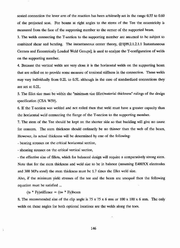
seated connection the lever arm of the reaction has been arbitrarily set in the range 0.55 to 0.60
of the projected seat. For beams at right angles to the stems of the Tee the eccentricity is
measured from the face of the supporting member to the center of the supported beam.
3. The welds connecting the T-section to the supporting member are assumed to be subject to
combined shear and bending. The instantaneous center theory, @1 [09.2.1.2.1.1 Instantaneous
Centers and Eccentrically Loaded Weld Groups], is used to analyze the T-configuration of welds
on the supporting member.
4. Because the vertical welds are very close it is the horizontal welds on the supporting beam
that are relied on to provide some measure of torsional stiffness in the connection. These welds
may vary individually from 0.2L to 0.5L although in the case of standardized connections they
are set at 0.2L.
5. The fillet size must be within the "minimum size fillet/material thickness" rulings of the design
specification (CSA W59).
6. If the T-section was welded and not rolled then that weld must have a greater capacity than
the horizontal weld connecting the flange of the T-section to the supporting member.
7. The stem of the Tee should be kept on the shorter side so that buckling will give no cause
for concern. The stem thickness should ordinarily be no thinner than the web of the beam,
However, its actual thickness will be determined by one of the following:
- bearing stresses on the critical horizontal section,
- shearing stresses on the critical vertical section,
- the effective size of fillets, which for balanced design will require a comparatively strong stem.
Note that for the stem thickness and weld size to be in balance (assuming E480XX electrodes
and 300 MPa steel) the stem thickness must be 1.7 times the fillet weld size.
Also, if the minimum yield stresses of the tee and the beam are unequal then the following
equation must be satisfied ...
(ts * Fy)stiffener = (tw * Fy)beam
8. The recommended size of the clip angle is 75 x 75 x 6 mm or 100 x 100 x 6 mm. The only
welds on these angles for both optional locations are the welds along the toes.
146
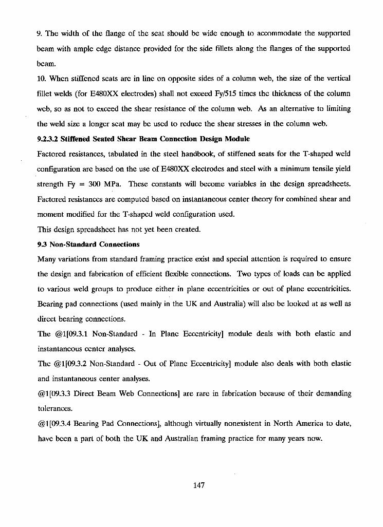
9. The width of the flange of the seat should be wide enough to accommodate the supported
beam with ample edge distance provided for the side fillets along the flanges of the supported
beam.
10. When stiffened seats are in line on opposite sides of a column web, the size of the vertical
fillet welds (for E480XX electrodes) shall not exceed Fy/515 times the thickness of the column
web, so as not to exceed the shear resistance of the column web. As an alternative to limiting
the weld size a longer seat may be used to reduce the shear stresses in the column web.
9.23.2 Stiffened Seated Shear Beam Connection Design Module
Factored resistances, tabulated in the steel handbook, of stiffened seats for the T-shaped weld
configuration are based on the use of E480XX electrodes and steel with a minimum tensile yield
strength Fy = 300 MPa. These constants will become variables in the design spreadsheets.
Factored resistances are computed based on instantaneous center theory for combined shear and
moment modified for the T-shaped weld configuration used.
This design spreadsheet has not yet been created.
93 Non-Standard Connections
Many variations from standard framing practice exist and special attention is required to ensure
the design and fabrication of efficient flexible connections. Two types of loads can be applied
to various weld groups to produce either in plane eccentricities or out of plane eccentricities.
Bearing pad connections (used mainly in the U K and Australia) will also be looked at as well as
direct bearing connections.
The @1 [09.3.1 Non-Standard - In Plane Eccentricity] module deals with both elastic and
instantaneous center analyses.
The @1 [09.3.2 Non-Standard - Out of Plane Eccentricity] module also deals with both elastic
and instantaneous center analyses.
@1 [09.3.3 Direct Beam Web Connections] are rare in fabrication because of their demanding
tolerances.
@1[09.3.4 Bearing Pad Connections], although virtually nonexistent in North America to date,
have been a part of both the U K and Australian framing practice for many years now.
147
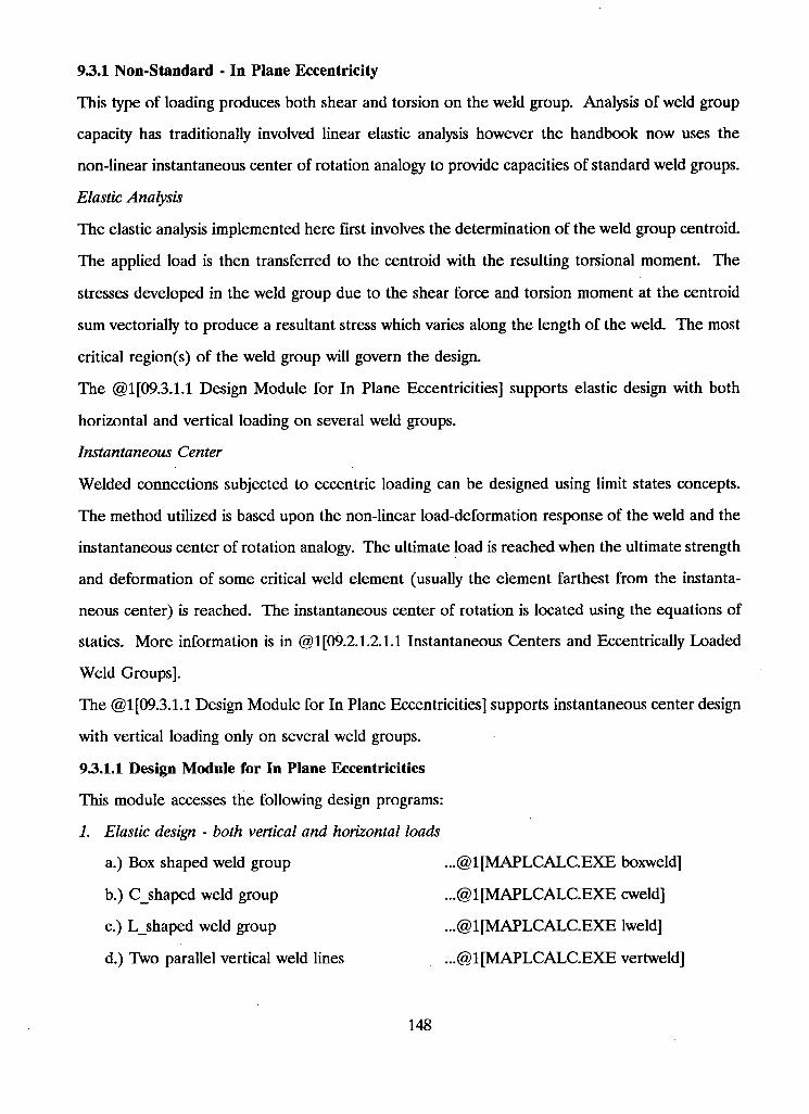
93.1 Non-Standard - In Plane Eccentricity
This type of loading produces both shear and torsion on the weld group. Analysis of weld group
capacity has traditionally involved linear elastic analysis however the handbook now uses the
non-linear instantaneous center of rotation analogy to provide capacities of standard weld groups.
Elastic Analysis
The elastic analysis implemented here first involves the determination of the weld group centroid.
The applied load is then transferred to the centroid with the resulting torsional moment. The
stresses developed in the weld group due to the shear force and torsion moment at the centroid
sum vectorially to produce a resultant stress which varies along the length of the weld. The most
critical region(s) of the weld group will govern the design.
The @1 [09.3.1.1 Design Module for In Plane Eccentricities] supports elastic design with both
horizontal and vertical loading on several weld groups.
Instantaneous Center
Welded connections subjected to eccentric loading can be designed using limit states concepts.
The method utilized is based upon the non-linear load-deformation response of the weld and the
instantaneous center of rotation analogy. The ultimate load is reached when the ultimate strength
and deformation of some critical weld element (usually the element farthest from the instanta
neous center) is reached. The instantaneous center of rotation is located using the equations of
statics. More information is in @1 [09.2.1.2.1.1 Instantaneous Centers and Eccentrically Loaded
Weld Groups].
The @1[09.3.1.1 Design Module for In Plane Eccentricities] supports instantaneous center design
with vertical loading only on several weld groups.
93.1.1 Design Module for In Plane Eccentricities
This module accesses the following design programs:
1. Elastic design - both vertical and horizontal loads
a.) Box shaped weld group ...@1 [ M A P L C A L C . E X E boxweld]
b. ) C_shaped weld group
c. ) L_shaped weld group
. . .@1[MAPLCALC.EXE cweld]
. . .@1[MAPLCALC.EXE lweld]
d.) Two parallel vertical weld lines . . .@1[MAPLCALC.EXE vertweld]
148
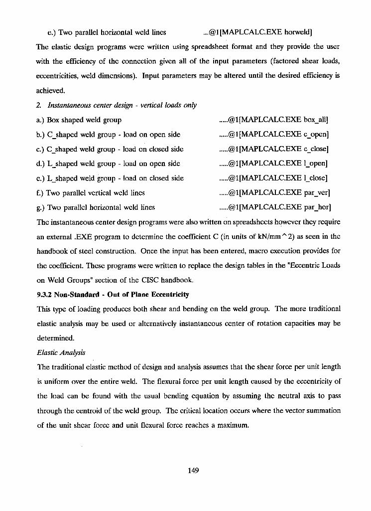
e.) Two parallel horizontal weld lines . . .@1[MAPLCALC.EXE horweld]
The elastic design programs were written using spreadsheet format and they provide the user
with the efficiency of the connection given all of the input parameters (factored shear loads,
eccentricities, weld dimensions). Input parameters may be altered until the desired efficiency is
achieved.
2. Instantaneous center design - vertical loads only
a. ) Box shaped weld group @1 [ M A P L C A L C . E X E box_all]
b. ) C_shaped weld group - load on open side @1 [ M A P L C A L C . E X E c_open]
c. ) Cshaped weld group - load on closed side @1[MAPLCALC.EXE cclose]
d. ) Lshaped weld group - load on open side @1 [ M A P L C A L C . E X E l_open]
e. ) L_shaped weld group - load on closed side @1 [ M A P L C A L C . E X E l_close]
f. ) Two parallel vertical weld lines @1 [ M A P L C A L C . E X E par_ver]
g. ) Two parallel horizontal weld lines @1 [ M A P L C A L C . E X E parjior]
The instantaneous center design programs were also written on spreadsheets however they require
an external . E X E program to determine the coefficient C (in units of kN/mm ^ 2) as seen in the
handbook of steel construction. Once the input has been entered, macro execution provides for
the coefficient. These programs were written to replace the design tables in the "Eccentric Loads
on Weld Groups" section of the CISC handbook.
93.2 Non-Standard - Out of Plane Eccentricity
This type of loading produces both shear and bending on the weld group. The more traditional
elastic analysis may be used or alternatively instantaneous center of rotation capacities may be
determined.
Elastic Analysis
The traditional elastic method of design and analysis assumes that the shear force per unit length
is uniform over the entire weld. The flexural force per unit length caused by the eccentricity of
the load can be found with the usual bending equation by assuming the neutral axis to pass
through the centroid of the weld group. The critical location occurs where the vector summation
of the unit shear force and unit flexural force reaches a maximum.
149
The @1 [09.3.2.1 Design Module for Out of Plane Eccentricities] supports elastic design, with
vertical loading only, on several weld groups.
Instantaneous Center Analysis
As with the in plane eccentricities, this method is also based on the load deformation capacity
of the weld group and the instantaneous center of rotation analogy. The one difference here is
that the bearing area of the connecting plate in the compression zone becomes a factor in the
analysis. The weld in the compression zone is assumed to carry shear only with the bearing
stresses being carried entirely by the plate. The handbook only tabulates coefficients for parallel
vertical welds, however with slight modifications in the analysis, many other weld configurations
may be dealt with. More information on this topic may be found in the module @1 [09.2.1.2.1.1
Instantaneous Centers and Eccentrically Loaded Weld Groups].
The @1 [09.3.2.1 Design Module for Out of Plane Eccentricities] supports instantaneous center
design with vertical loading for a few standard weld groups.
93.2.1 Design Module for Out of Plane Eccentricities
Options in this design module include the following:
1. Elastic design - vertical loading
a. ) Box shaped weld group
b. ) Single vertical weld line
c. ) Two parallel vertical weld lines
d. ) Two parallel horizontal weld lines
The elastic design programs were written on spreadsheets and they provide the user with the
efficiency of the connection given all of the input parameters (factored shear loads, eccentricities,
weld dimensions). Input parameters may be altered until the desired efficiency is achieved.
2. Instantaneous center design - vertical loading
a. ) Box shaped weld group
b. ) single vertical weld line
c. ) Two parallel vertical weld lines
d. ) Two parallel horizontal weld lines
150
The instantaneous center design programs were also written on spreadsheets however they must
run an external . E X E program to determine the coefficient C (in units of kN/mm ~ 2) as seen
in the handbook of steel construction. Once the input has been entered, macro execution
provides for the coefficient, C. These programs were written to replace the design tables in the
"Eccentric Loads on Weld Groups" section of the CISC handbook.
9.3.3 Direct Beam Web Connections
Although this connection is quite rare in fabrication, it may be theoretically acceptable as a flexible
connection with the proper detailing to produce low resistance to bending while still maintaining
safe shear transfer.
Connection flexibility may be supplied by the supporting member as in the case of a supporting
beam or girder. If the supporting member is essentially rigid than the rotation capacity must
come from the weld detail which should be made short enough and stout enough to produce
prior yielding in the supported beam web. The weld will be short enough if it is not greater than
two thirds the depth of the beam and stout enough if its thickness is greater than four fifths the
thickness of the supported beam web.
Practically speaking this connection has some serious drawbacks. There is no support for the
beam inherent in this connection and therefore temporary supports are required before and
during welding that must be removed later so as not to impair the flexibility of the connection.
Also, the tight fit-up conditions necessary for producing effective fillet welds conflict with the
erection clearances necessary for ease of construction. A comfortable compromise of say 3 mm
would be difficult to achieve because of square cutting tolerances on the supported beam and
rolling tolerances on the supporting column.
93.4 Bearing Pad Connections
One component in this connection consists of an end plate which is shop welded to either the
upper end, the lower end, or the full depth of the beam. The end plate location determines the
center of rotation for the beam end. Field bolting is accommodated with two holes in the bottom
of the end plate. The end plate bears onto a bearing pad which is shop welded to the supporting
member. A shimming plate may be used to control the erection gap.
151
The load is considered to be transferred by shearing and bearing. The end plate length and
connecting welds are governed by shear. Beam web buckling and connection torsional stability
should be checked under critical conditions.
As with the direct beam-web connection this connection also has some serious practical draw
backs. The mill tolerances on the column depths are very demanding in order to ensure the
required minimum bearing length is achieved. Great care must be taken to ensure the accurate
placement of both the end plate and the bearing pad.
152
10 Moment Connections
Welding is most efficient in structures designed for continuity. Rigid frame or continuous con
struction demands moment resisting beam-to-column connections. @l[moment2.pcx] illustrates
a common rigid connection.
Frye and Morris demonstrated that all connections will develop a moment if the rotation becomes
large enough. The diagram in @1 [Momentl.pcx], which illustrates moment rotation curves for
various connections, was developed by Frye and Morris. It can be seen from the diagram that
varying degrees of end fixity produce varying degrees of connection rigidity. The most important
difference between the rigid and semi-rigid connections is the magnitude of moment that the
connection will develop at small rotations. The rigid connection will develop the full beam
moment at relatively small rotations.
Under service conditions, it is assumed that rigid connections possess sufficient rigidity to
maintain, virtually unchanged, the original angles between the beams and the columns with which
they connect. In addition to adequate strength and stiffness, suitable rotation capacity (ie. ductile
behavior) is required to permit inelastic deformations to occur. These inelastic deformations are
necessary in developing the full strength of the connection.
The high degree of restraint associated with the rigid connection demands careful design con
siderations to properly handle possible stress concentrations. In elastically analyzed structures,
stress concentrations are alleviated through small amounts of yielding. Plastically designed
structures depend on connection ductility to enable the large amounts of yielding necessary for
the redistribution of moments.
The beam end moments lead to both tensile and compressive flexural stresses that must be
transferred into the column. This transfer may be accomplished directly or with the use of
separate plate material. Similarly, shear transfer may be provided with a direct groove weld on
the beam flange or with plated material such as header angles, one-sided plates, or seats.
@1 [moment3.pcx] illustrates both direct and plated flexural stress transfer. @ljmoment4.pcx]
shows the same only for shear.
153
In many instances, column stiffeners will be required to prevent local failures from destroying
the integrity of the connection. Laminations existing in the column flange plate could also lead
to failure, especially when welding under conditions of restraint. Refer to @1[06.4 lamelar
tearing].
Built up column sections require additional considerations to ensure the web to flange weld
develops the required capacity.
The Designer must provide the Fabricator with complete information regarding moments and
shears to be developed by the connection. Because weld inspection plays such an important role
in maintaining quality control, the Designer together with the Fabricator should determine the
type and degree of inspection prior to fabrication to avoid unforeseen problems.
10.1 Rigid and Semi-Rigid Connections
Semi-rigid connections:
In semi-rigid connections, the beam is designed for the total elastic moment less the moment
developed by the end connection. Unfortunately, it is no easy task to determine the moment
developed by the end connection.
Semi-rigid connections are not often used for the following reasons:
1. The stiffness of the connection is difficult to define and, therefore, the structural analysis is
more complicated. As such, the analysis is less well understood by design engineers.
2. The moment rotation curves used in the analysis must be determined from physical testing on
full scale specimens.
3. Both simple and rigid connections have become more standardized over the years while
semi-rigid connections still remain the hazy field in between.
Rigid connections:
Rigid connections develop the maximum beam moment while maintaining suitable rotation
capacity. In order to maintain the integrity of this connection, the following considerations apply:
1. Local buckling of essential elements must be prevented.
2. The criterion for stiffening of the column web opposite the compression flange of the beam
must be examined.
154
3. Similarly, the criterion governing the use of stiffeners opposite the tension flange of the beam
must be investigated.
4. The column may need to be reinforced to handle combined axial and local stresses.
5. The connection must deliver rotation capacity demands.
Note that clause 21.3, Restrained Members, of S16.1-89 defines the requirements for the stiffeners
in points 1 and 2 above.
10.2 Column Stiffeners
It is mostly the column which requires a thorough examination of its critical elements. Such
investigation will include a check on requirements for:
1. Stiffening of the column web to prevent crippling under the compressive flexural flange load
of the beam;
2. Stiffening of the column flanges for the tensile flexural flange load of the beam to prevent
their deformation and ensure a reasonably uniform stress distribution in the tension joint of the
beam;
3. Reinforcing of the column web to maintain shear stresses within those permissible;
4. Reinforcing of the column web-to-flange weld for build-up columns for all cases of excessive
longitudinal shear stress in such welds.
The first three point have to be satisfied in light of the pertinent requirements of CSA Standard,
S16.1-M89 Limit States Design of Steel Structures. In particular, clause 21.3, Restrained
Members, gives requirements for stiffeners provided on the column web when beams are rigidly
framed into the flange of an H-type column.
The resistance of the column section to local deformation is crucial for developing the full
connection capacity. Column web yielding in tension or compression or column web buckling
will seriously impair the moment carrying capacity of the connection. The use of stiffeners or
doubler plates may be necessary for local strengthening of the column. Doubler plates are
commonly used to increase the column web shear capacity in the panel zone. Inclined stiffeners
may also be used to achieve the same result. If the plastic shear capacity, 0.55(phi)(w)(d)(Fy),
of the panel zone is exceeded then stiffeners are required.
155
Weld failure in tension, usually from non-uniform stress distribution, is another possible mode of
failure. A horizontal column stiffener adjacent to the beam tension flange will virtually eliminate
the curling of the column flanges which would otherwise tend to overstress the central portion
of the weld between the tension flange and the column. Horizontal column stiffeners are also
used adjacent to the beam compression flange to prevent buckling of the column web. One sided
stiffeners need only extend to one half of the column depth provided the welds connecting the
stiffener to the column web develop ... P = A(st) x F(y).
On those occasions when beam flanges framing in from opposite sides of the column are at
different heights, inclined stiffeners or two horizontal stiffeners may be used. According to
Graham, Sherbourne, and Khabbaz, if the difference in flange height is less than 50 mm then
only one stiffener need be used, however the stiffener thickness must be increased by a factor
of 1.7. Three methods of framing for eccentric flange connections are shown in @l[mo-
ment9.pcx], @l[momentl0.pcx], and @l[momentll.pcx].
A [test comparison of stiffener types] gives a brief summary on rigid beam-to-column connection
testing done through the AISC in 1959.
10.2.1 S16.1-M89 213 Restrained Members
When beams, girders, or trusses are subject to both reaction shear and end moment due to full
or partial end restraint or to continuous or cantilever construction, their connections shall be
designed for the combined effect of shear, bending, and axial load. When beams are rigidly
framed to the flange of an H-type column, stiffeners shall be provided on the column web as
follows:
(a) opposite the compression flange of the beam when
see [restrain.pcx]
except that for members with Class 3 or a webs,
see [restrain.pcx]
(b) opposite the tension flange of the beam when
Tr = 7 [phi] (tc) ~ 2 Fyc < Mf / db
where
wc = thickness of column web
156
tb = thickness of beam flange
k = distance from outer face of column flange to web-toe of fillet, or to web-toe of flange-to-web
weld in a welded column
Fyc = specified yield point of column
db = depth of beam
he = clear depth of column web
tc = thickness of column flange
The stiffener or pair of stiffeners opposite either beam flange must develop a force equal to
Fst = {Mf / db} - Br
Stiffeners shall also be provided on the web of columns, beams, or girders if Vr calculated from
Clause 13.4.2 is exceeded, in which case the stiffener or stiffeners must transfer a shear force
equal to
Vst = V f - 0.55 [phi] w d Fy
In all cases, the stiffeners shall be connected so that the force in the stiffener is transferred
through the stiffener connection. When beams frame to one side of the column only, the
stiffeners need not be longer than one-half of the depth of the column.
10.2.2 Test Comparison of Stiffener Types
1. Direct beam-to-column flange connection without the use of column stiffeners. Refer to
@l[momentl2.pcx]. In the actual connection tested, the beam was stiffer against rotation than
the column. As would be expected, the beam tension flange normal stress distribution showed
higher concentrations of stress at the center of the flange. Although the connecting groove weld
also showed the same stress concentration, no weld failures occurred until after excessive rotation
had taken place.
2. Horizontal stiffeners are added to the column adjacent to both beam flanges. Refer to
@l[momentl3.pcx]. The column is now as stiff against rotation as the beam. The normal stress
distribution in the beam's compression flange was essentially uniform however the tension flange
still exhibited higher magnitudes of stress in the center.
157
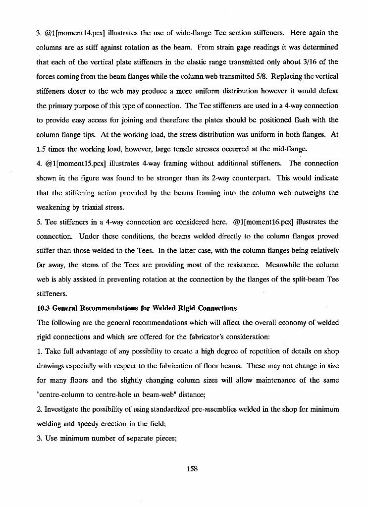
3. @l[momentl4.pcx] illustrates the use of wide-flange Tee section stiffeners. Here again the
columns are as stiff against rotation as the beam. From strain gage readings it was determined
that each of the vertical plate stiffeners in the elastic range transmitted only about 3/16 of the
forces coming from the beam flanges while the column web transmitted 5/8. Replacing the vertical
stiffeners closer to the web may produce a more uniform distribution however it would defeat
the primary purpose of this type of connection. The Tee stiffeners are used in a 4-way connection
to provide easy access for joining and therefore the plates should be positioned flush with the
column flange tips. At the working load, the stress distribution was uniform in both flanges. At
1.5 times the working load, however, large tensile stresses occurred at the mid-flange.
4. @l[momentl5.pcx] illustrates 4-way framing without additional stiffeners. The connection
shown in the figure was found to be stronger than its 2-way counterpart. This would indicate
that the stiffening action provided by the beams framing into the column web outweighs the
weakening by triaxial stress.
5. Tee stiffeners in a 4-way connection are considered here. @l[momentl6.pcx] illustrates the
connection. Under these conditions, the beams welded directly to the column flanges proved
stiffer than those welded to the Tees. In the latter case, with the column flanges being relatively
far away, the stems of the Tees are providing most of the resistance. Meanwhile the column
web is ably assisted in preventing rotation at the connection by the flanges of the split-beam Tee
stiffeners.
103 General Recommendations for Welded Rigid Connections
The following are the general recommendations which will affect the overall economy of welded
rigid connections and which are offered for the fabricator's consideration:
1. Take full advantage of any possibility to create a high degree of repetition of details on shop
drawings especially with respect to the fabrication of floor beams. These may not change in size
for many floors and the slightly changing column sizes will allow maintenance of the same
"centre-column to centre-hole in beam-web" distance;
2. Investigate the possibility of using standardized pre-assemblies welded in the shop for minimum
welding and speedy erection in the field;
3. Use minimum number of separate pieces;
158
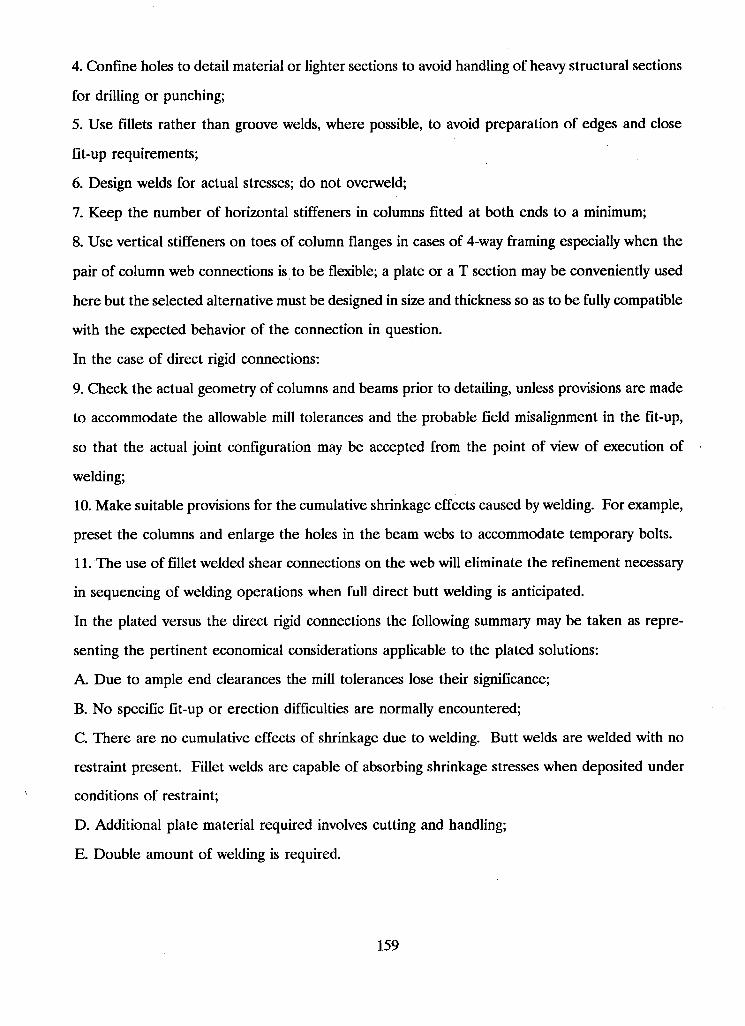
4. Confine holes to detail material or lighter sections to avoid handling of heavy structural sections
for drilling or punching;
5. Use fillets rather than groove welds, where possible, to avoid preparation of edges and close
fit-up requirements;
6. Design welds for actual stresses; do not overweld;
7. Keep the number of horizontal stiffeners in columns fitted at both ends to a minimum;
8. Use vertical stiffeners on toes of column flanges in cases of 4-way framing especially when the
pair of column web connections is to be flexible; a plate or a T section may be conveniently used
here but the selected alternative must be designed in size and thickness so as to be fully compatible
with the expected behavior of the connection in question.
In the case of direct rigid connections:
9. Check the actual geometry of columns and beams prior to detailing, unless provisions are made
to accommodate the allowable mill tolerances and the probable field misalignment in the fit-up,
so that the actual joint configuration may be accepted from the point of view of execution of
welding;
10. Make suitable provisions for the cumulative shrinkage effects caused by welding. For example,
preset the columns and enlarge the holes in the beam webs to accommodate temporary bolts.
11. The use of fillet welded shear connections on the web will eliminate the refinement necessary
in sequencing of welding operations when full direct butt welding is anticipated.
In the plated versus the direct rigid connections the following summary may be taken as repre
senting the pertinent economical considerations applicable to the plated solutions:
A. Due to ample end clearances the mill tolerances lose their significance;
B. No specific fit-up or erection difficulties are normally encountered;
C. There are no cumulative effects of shrinkage due to welding. Butt welds are welded with no
restraint present. Fillet welds are capable of absorbing shrinkage stresses when deposited under
conditions of restraint;
D. Additional plate material required involves cutting and handling;
E. Double amount of welding is required.
159
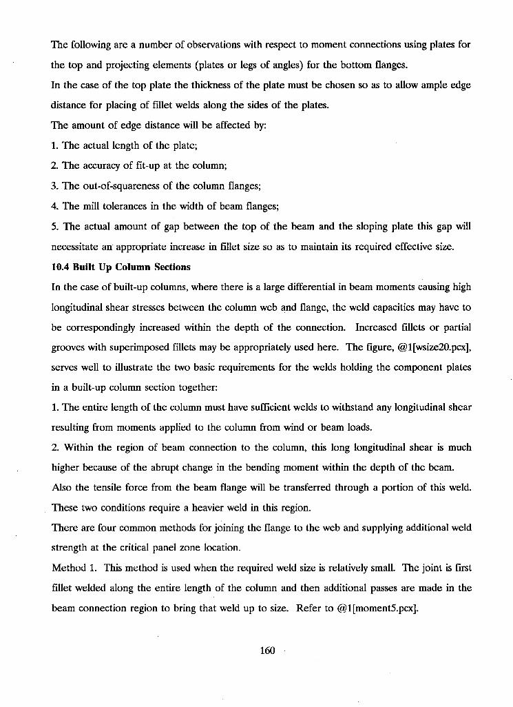
The following are a number of observations with respect to moment connections using plates for
the top and projecting elements (plates or legs of angles) for the bottom flanges.
In the case of the top plate the thickness of the plate must be chosen so as to allow ample edge
distance for placing of fillet welds along the sides of the plates.
The amount of edge distance will be affected by:
1. The actual length of the plate;
2. The accuracy of fit-up at the column;
3. The out-of-squareness of the column flanges;
4. The mill tolerances in the width of beam flanges;
5. The actual amount of gap between the top of the beam and the sloping plate this gap will
necessitate an appropriate increase in fillet size so as to maintain its required effective size.
10.4 Built Up Column Sections
In the case of built-up columns, where there is a large differential in beam moments causing high
longitudinal shear stresses between the column web and flange, the weld capacities may have to
be correspondingly increased within the depth of the connection. Increased fillets or partial
grooves with superimposed fillets may be appropriately used here. The figure, @l[wsize20.pcx],
serves well to illustrate the two basic requirements for the welds holding the component plates
in a built-up column section together:
1. The entire length of the column must have sufficient welds to withstand any longitudinal shear
resulting from moments applied to the column from wind or beam loads.
2. Within the region of beam connection to the column, this long longitudinal shear is much
higher because of the abrupt change in the bending moment within the depth of the beam.
Also the tensile force from the beam flange will be transferred through a portion of this weld.
These two conditions require a heavier weld in this region.
There are four common methods for joining the flange to the web and supplying additional weld
strength at the critical panel zone location.
Method 1. This method is used when the required weld size is relatively small. The joint is first
fillet welded along the entire length of the column and then additional passes are made in the
beam connection region to bring that weld up to size. Refer to @1 [moment5.pcx].
160
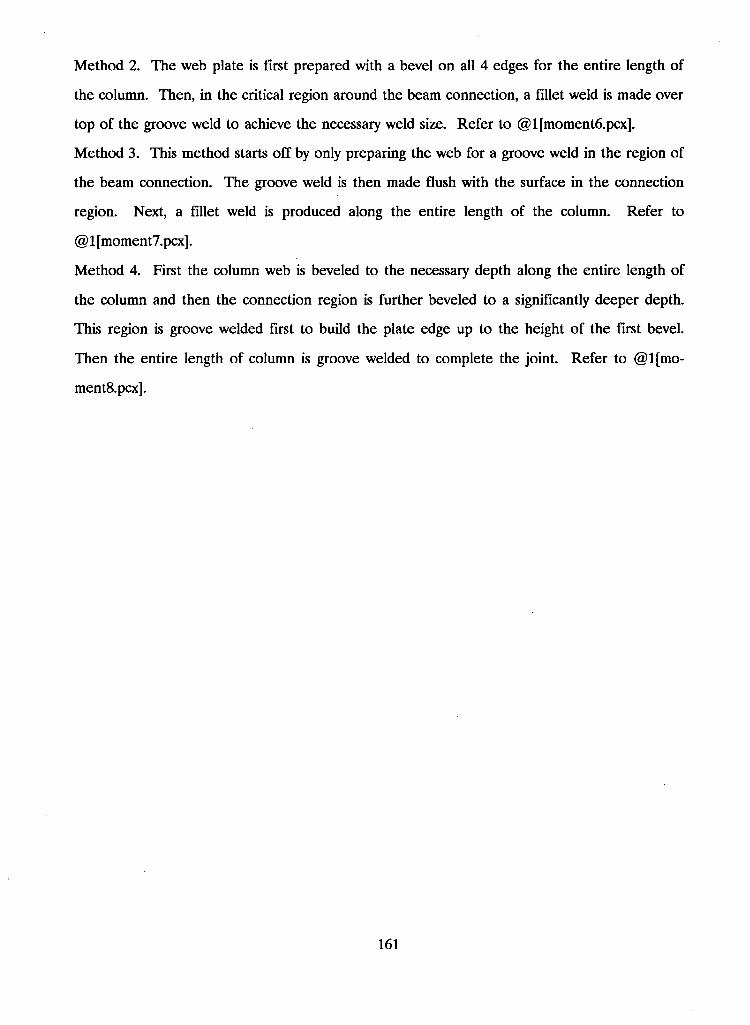
Method 2. The web plate is first prepared with a bevel on all 4 edges for the entire length of
the column. Then, in the critical region around the beam connection, a fillet weld is made over
top of the groove weld to achieve the necessary weld size. Refer to @1 [moment6.pcx].
Method 3. This method starts off by only preparing the web for a groove weld in the region of
the beam connection. The groove weld is then made flush with the surface in the connection
region. Next, a fillet weld is produced along the entire length of the column. Refer to
@ 1 [moment7.pcx].
Method 4. First the column web is beveled to the necessary depth along the entire length of
the column and then the connection region is further beveled to a significantly deeper depth.
This region is groove welded first to build the plate edge up to the height of the first bevel.
Then the entire length of column is groove welded to complete the joint. Refer to @l[mo-
ment8.pcx].
161
ACKNOWLEDGEMENT
I would first like to acknowledge the generous contributions of the Canadian Welding Bureau
who along with their help and assistance throughout the development of the project also provided
a significant portion of the financial requirements. In addition, notable contributions from the
Government of British Columbia and the University of British Columbia must also be acknowl
edged. The WISDOM system was made a reality because of these essential groups.
In order to ensure the practical relevance of the engineering topics considered in this project,
an advisory board was enlisted for their experience and guidance. I would now like to thank the
members of this board: Mr. M . Frank (CANRON), Mr. D. Halliday (COAST STEEL), Mr. A.
Ho (CSFM), Mr. D. Reynolds (PRESIDENT, CWB), and Mr. A . McCartney (CWB).
The inspiration of Dr. Siegfried F. Stiemer played a prominent role during my post graduate
term. His patience and understanding throughout the duration of the thesis is greatly appreciated.
Finally, I would like to thank my wife, Maureen, for her patience and understanding during the
entire course of my studies. 0
162
GLOBAL REFERENCES
1. CSA W59-M1989 Welded Steel Construction (Metal Arc Welding), Published in January of 1989
by Canadian Standards Association, 178 Rexdale Boulevard, Rexdale (Toronto), Ontario, Canada,
M9W 1R3.
2. CSA W47.1-1983 Certification of Companies for Fusion Welding of Steel Structures, Published
in December of 1983 by Canadian Standards Association, 178 Rexdale Boulevard, Rexdale
(Toronto), Ontario, Canada, M9W 1R3.
3. Althouse, Andrew D., Turnquist, Carl H., Bowditch, William A., and Bowditch, Kevin E.,
Modern Welding, The Goodheart-Willcox Company, Inc., 1988.
4. Gray, T. G. F. And Spence, J., Rational Welding Design, 2nd Edition, Butterworth & Co.
(Publishers) Ltd., 1982.
5. Masubuchi, Koichi, Analysis of Welded Structures, Pergamon Press Ltd., 1980.
6. Bjorhovde, Reidar, Welded Connections - Steel Grade Selection and Design Considerations,
Professor of Civil Engineering and Engineering Mechanics, University of Arizona, Tucson, Ari
zona, U.S.A.
7. Blodgett, O. W., Detailing to Achieve Practical Welded Fabrication, Engineering Journal, Vol.
17, No. 4, 1980, pp. 106-119.
8. Blodgett, Omer W., Weld Failures: They Could be the Result of Violating Simple Design Prin
ciples, Welding Journal, March 1982.
9. Blodgett, Omer W., Weld Failures: They Could be the Result of Violating Simple Design Principles
- Part II, Welding Journal, April 1982.
10. Blodgett, Omer W., Design of Welded Structures, The James F. Lincoln Arc Welding Foun
dation, Twelfth Pinting March 1982.
11. Stout, Robert D. And Doty, W. D'Orville, Weldability of Steels, Welding Research Council,
1953.
12. Grover, LaMotte, Manual of Design for Arc Welded Steel Structures, Air Reduction Sales Co.,
New York, N.Y., 1949.
13. CISC Handbook of Steel Construction, Fourth Edition, Second Printing July 1986, Canadian
Institute of Steel Construction, Willowdale, Ontario.
163
14. CAN/CSA-S16.1-M1989 Limit States Design of Steel Structures, Canadian Standards Associ
ation, Rexdale, Ontario, December 1989.
15. Thadani, B. N . And Rizkalla, S. H. , Structural Steel Design with CAN3-S16.1-M84, Cantext
Publications, Winnipeg, Canada, 1986.
16. Biskup, J. T. And King, C.S., CISC Atlantic Region - Welding Engineering Seminar, St. John,
N.B., November 17-20, 1981.
17. Plummer, Charles C. And McGeary, David, Physical Geology, Third Edition, Wm. C. Brown
Publishers, Dubuque, Iowa, 1985.
18. Richard, Ralph M . , Gillett, Paul E., Kriegh, James D., And Lewis, Brett A , The Analysis and
Design of Single Plate Framing Connections, AISC Engineering Journal, 17(2) pp. 38-52, 1980.
19. Kriviak, Gary J. And Kennedy, D. J. Laurie, Standardized Flexible End Plate Connections for
Steel Beams, Canadian Journal of Civil Engineering, Volume 12, 1985.
20. Pillinger, A H., Structural Steelwork: A Flexible Approach to the Design of Joints in Simple
Construction, The Structural Engineer, Volume 66, No. 19, October 1988.
21. Mansell, D. S. And Pham, L., Testing of Standardized Connections, Metal Structures Con
ference, New Castle, May 11-14, 1981.
22. White, Richard N., Framing Connections for Square and Rectangular Structural Tubing, AISC
Engineering Journal, pp 94-102, July, 1965.
23. Hogan, T. J. And Firkins, A , Standardized Structural Connections - Five Years On, Steel
Construction Journal, Australian Institute of Steel Construction, Volume 17, Number 2, pp 2-10,
1983.
24. Bennetts, I. D., Thomas, I. R. And Grundy, P., Shear Connections for Beams to Columns,
Metal Structures Conference, Perth, Nov. 30 - Dec. 1,1978.
25. Disque, Robert O., End Plate Connections, Thursday Afternoon Session, Proceedings -
National Engineering Conference, AISC, April 12, 1962.
26. McClellan, R. W., One-Sided Welding of High-Yield Steels, Presented at 69th Annual AWS
Convention, New Orleans, La., April 17-22, 1988.
27. Weber, J., Cullison, A And Leonard, R., Steel vs. Concrete: Which Offers the Most for Hea\y
construction?, The Welding Journal, May, 1988.
164
28. Kennedy, D. J. Laurie and Kriviak, Gary J., The Strength of Fillet Welds under Longitudinal
and Transverse Shear: A Paradox, Canadian Journal of Civil Engineering, Volume 12, pp 226-231,
1985.
29. Dawe, J. L., Pond, B. S. And Grondin, G. Y. , Interaction of Shear and Tension in Welded
Truss Connections, Canadian Journal of Civil Engineering, Volume 12, pp 94-103, 1985.
30. Young, Ned W. And Disque, Robert O., Design Aids for Single Plate Framing Connections,
AISC Engineering Journal, Fourth Quarter, 1981.
31. Kennedy, D. J. L., Moment-Rotation Characteristics of Shear Connections, AISC Engineering
Journal, October, 1969.
32. Watson, Paul D., Design for Welding Examination, The Welding Journal, February, 1982.
33. Reeves, R. E., Manley, T. D., Potter, A . And Ford, D. R., Expert System Technology - An
Avenue to an Intelligent Weld Process Control System, The Welding Journal, June, 1988.
34. Birkemore, Peter C. And Gilmor, Michael I., Behavior of Bearing Critical Double-Angle Beam
Connections, AISC Engineering Journal, Fourth Quarter, 1978.
35. Kulak, G. L. And Timler, P. A., Tests on Eccentrically Loaded Fillet Welds, Structural Engi
neering Report No. 24, December, 1984.
36. Crawford, Sherwood F. And Kulak, Geoffrey L., Eccentrically Loaded Bolted Connections,
Journal of the Structural Division, Proceedings of the ASCE, March, 1971.
36. Butler, Lome J., Pal, Shubendu and Kulak, Geoffrey L., Eccentrically Loaded Welded Con
nections, Journal of the Structural Division, Proceedings of the ASCE, May, 1972.
37. Dawe, John L. And Kulak, Geoffrey L., Welded Connections Under Combined Shear and
Moment, Journal of the Structural Division, Proceedings of the ASCE, April, 1974.
165