Embed Size (px)
Citation preview
The Space Congress® Proceedings 1976 (13th) Technology For The New Horizon
Apr 1st, 8:00 AM
Welding At Kennedy Space Center Welding At Kennedy Space Center
William E. Clautice NASA - Design Engineering, Kennedy Space Center, Florida
Follow this and additional works at: https://commons.erau.edu/space-congress-proceedings
Scholarly Commons Citation Scholarly Commons Citation Clautice, William E., "Welding At Kennedy Space Center" (1976). The Space Congress® Proceedings. 3. https://commons.erau.edu/space-congress-proceedings/proceedings-1976-13th/session-4/3
This Event is brought to you for free and open access by the Conferences at Scholarly Commons. It has been accepted for inclusion in The Space Congress® Proceedings by an authorized administrator of Scholarly Commons. For more information, please contact [email protected].
WELDING AT THE KENNEDY SPACE CENTER
William E, ClauticeNASA - Design Engineering
Kennedy Space Center, Florida
ABSTRACT
Welding plays a major role in the design, manufac ture, and construction of the ground support equip ment at the Kennedy Space Center.
Three applications of welding are described, i.e., an example of the structural welding of a girder in a mobile launcher (presently designated mobile launcher platform), an example of the repair welding of crawler/transporter shoes, and an example of the welding of the liquid hydrogen and liquid oxygen storage spheres and vacuum jacketed piping in the propel 1 ants system.
This welding technology was developed during the Apollo and earlier programs. It is now being ap plied to the Space Shuttle.
KSC WELDING SPECIFICATIONS AND PROCESSES
The welding of GSE, at the Kennedy Space Center is specified in the design phase to meet certain en gineering requirements. These requirements are sti pulated in welding specifications generated in the Design Engineering Directorate of the Kennedy Space Center. A list of Kennedy Space Center (KSC) Weld ing Specifications is given in Table 1.
Gas tungsten-arc welding is the process most used on the critical piping of the major systems on the launch sites at the Kennedy Space Center. GTAW is used in welding the 36% nickel and stainless steel piping in vacuum jacketed lines in the propellants system. It is used to weld the aluminum alloy piping in the environmental control system. G1AW is used also in welding the high pressure piping in the pneu matic system.
The gas metal arc welding process was used in weld ing the vessels for liquid hydrogen and liquid oxy gen storage in the propellants system.
The shielded metal-arc welding process (SMAW) and the submerged arc welding process (SAW) were used extensively on the heavy structural sections of the mobile launcher and the transporter/crawler.
The welding processes now used at the Kennedy Space
Center are:
• Shield metal-arc welding (SMAW)• Gas tungsten-arc welding (GTAW)• Submerged arc welding (SAW)• Induction brazing (IB)• Torch brazing (TB)
WELDING MOBILE LAUNCHER GIRDERS
One typical application of structural welding is the welding of the girders in mobile launchers. There are several large girders in the base of a mobile launcher. One centrally located girder, (G-14), Figure 1, is described as typical. The girder is 135 feet long and 25 feet high. The web is constructed of steel plate 1% inches thick. The top and bottom flanges are constructed of steel plate six inches thick.
The base metals used in the construction of the gird er conform to ASTM A 36 Specification for Structural Steel and ASTM A 441 Specification for High Strength Low Alloy Structural Manganese Vanadium Steel.
The weld filler metal used for manual shielded metal arc welding was AWS A 5.1 Class E7018. The filler metal and flux combined in submerged arc welding were Grade SAW-2 of the American Institute of Steel
Construction.
The girder was prefabricated at the contractor's plant in six parts, consisting of two identical end sections and four inner sections. These were mas sive parts, each weighing approximately 40 tons.
The six prefabricated parts of the girder were shipped to Kennedy Space Center where the field erection was performed at the mobile launcher (ML) parking site adjacent to the Vehicle Assembly Building (VAB). As this was to be the permanent parking site for the mobile launchers, it was cover ed with a level, hard top, asphalt surface. The geometry for the control of the erection of the mobile launchers was laid out on the asphalt surface of the parking site. The locations and dimensions of the cribbing and blocking needed for their con struction were established on this layout.
The G-14 girder was assembled on the ML parking site in the following manner:
1. Initially, the four inner sections of the girder were fitted together on blocking sufficiently heavy to hold the dead weight and to facilitate maintain ing the camber. They were braced in the vertical position with steel guy cables. The welds splicing together the four inner sections were made in the sequence 1, 2, 3 shown in Figure 2. This sequence minimized distortion and maintained the beam camber within the 9/16 inch tolerance for the complete gird er. Camber was checked by periodic rod readings.
2. After the four inner sections were welded to-
4-79
gather on the blocking* the entire inner section subassembly was 11 ted onto false work supports set up in place at the final erection location of the girder on the parking site. The move was limited to one lift because of extreme weight. The sub- assembly was hung with its bottom flange at an ele vation of approximately 20 feet from the ground. Here it was joined to other girders such as G-3 and 6-9 shown in Figure 3. Next the end sections were lifted into place and splice welded in the sequence 4, 5» and 6 shown previously 1n Figure L During the welding of the end sections* they were bolted to the tripod-like mount mechanisms* Figure 3. The mount mechanisms are large screw jacks, permanently installed at the parking site to secure the mobile launchers during parking,
3, During the splicing of the girder, the flangewas welded at six locations (Figure 2). These welds were applied in multiple passes using the sub merged arc welding process, The joint design and welding data are shown in Figure 4, The flange splice welds were 100% radiographically inspected to UW 51 of the ASME Code.
4* The web was spliced by a total of 3968 inches of welding applied by the shielded metal arc welding process with E7018 electrodes. The joint design was an AWS prequalified type, B-U5 for the horizontal position and B-U3 for the vertical position. These welds were complete penetration groove welds quali fied for unlimited thickness. The welding was radiographically inspected by spot-examination to UW-52 of the ASME Code.
5. Joints that bore identical sequence numbers were welded simultaneously.
6. All weld joints of the same sequence numbers were completed before starting joints having highersequence numbers,
7* Shims 1/8 inch thick were placed between all erection angles at the splices to assure the butt weld root opening and to allow for shrinkage during the welding of web and flange joints.
8. Welded groove joints made without backing were back-gouged to sound metal by the air carbon-arc process before welding the opposite side.9. Erection angles and runoff bars were removed after the welding was completed.
10. All layers in thick joints* except the firstand last layer were allowed to be peened to reduce shrinkage and distortion.
The weld quality was maintained at a. high level throughout the construction of the mobile launcher girders. The design specified radiograph!c in spection of the field splice welds in the girder flanges and girder webs. The requirement was radiographic inspection in accordance with UW-51 of the ASME Code for the girder flange splice welds and UW-52 for the web splice welds*
Fillet welds were inspected visually for size, con
tour and conformance to the acceptance standards specified in the design, (AWS Dl.l), Bridge Code.Certain large groove welds in heavy sections were inspected for cracks using the magnetic particle method of inspection.
The welding of girder 6-14 is typical of the weld ing of the largest girders in the mobile launchers at the Kennedy Space Center. The'girder was welded in accordance with Kennedy Space Center welding specification KSC-SPEC-Z-004, and AWS Dl.l, Struc tural Welding Code, Section 9, Bridges. The girder is unique in its role of providing major support to loads in one of the largest existing mobile struc tures. The methods of welding, joint designs, and inspection methods are described.
As a final item of data of general interest, the total linear inches of welding on girder G-14 are tabulated in Table 2. Weld sizes and types range from k inch fillet welds to six inch thick butt welds in flange splices and column connections. The linear inches of welding of all types total 76,254 inches, or well over a mile of welding in the G-14 girder.
REPAIR WELDING OF CRAWLER TRANSPORTER SHOES
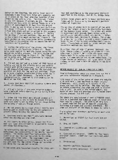
Crawler/transporter shoes are shown laid out for a periodic maintenance inspection in Figure 5.Worn areas of the roller paths of shoes are rebuilt with weld metal, then machined to their original dimensions. Also, cracks particularly in lug areas are repaired by welding. The lugs function to retain connecting pins when the shoe is coupled into a'belt. As part of the refurbishment, the bores of worn lugs are provided with hardened steel sleeves pressed into the lugs.
The shoes are manufactured of cast AISI86B30 steel. This is a quenched and tempered steel of relatively high tensile strength. The welding of this type of steel requires the use of special .procedures, including a preheat and postheat treatment. The chemical analysis of the shoes is shown in Table 3.The original heat treatment performed on each shoe was as follows:
1. Normalized at 1750°F for four hours and; air cooled,
2. Draw at TI50°F.
3. Cleaned and shotbiasted, Magnetic particle inspected,
4. Quenched and tempered. 1700°F for four hoursand water quench,. 1180° for four hours and water quench*
5. Shotblasted.
6. Magnetic particle inspected*7. Repair welding necessary, If repair welded
4-80

then stress relieved at 1150° for four hours and water quenched.
The mechanical properties of the shoes are given in Table 4.
The need for a preheat treatment is illustrated by reference to an isothermal transformation diagram for the steel, Figure 6. An isothermal transforma tion diagram is a plot on cartesian coordinates of temperature versus time depicting the various met allurgical structures resulting from differerent cooling rates for a particular steel. The diagram shows that the weld and heat affected zone in this steel when cooled rapidly (1 minute or less) from above 1600°F to below 300°F will transform from the high temperature gamma iron or austenite phase to a hard, brittle martensite. The brittle martensite can cause the weldment to be low in impact proper ties and highly susceptible to cracking, obviously undesirable properties.
In contrast, if the weld is cooled more slowly or held sufficiently long above the martensite comple tion temperature, it will form a more ductile met allurgical structure, such as that consisting of a fine perlite and tempered martensite. In any case, the final metallurgical structure existing at room temperature is a function of the cooling rate. In general, the slower the cooling rate, the more ductile is the resulting metallurgical structure. This increase in ductility is associated with some reduction in strength. Therefore, it is desirable to determine the optimum metallurgical structure; i.e., one with adequate strength and good ductil ity. At this point, the logic of applying a pre heat becomes apparent, because by means of a pre heat, we can retard the cooling rate in the weld and thereby control the resulting metallurgical structure and associated weld properties.
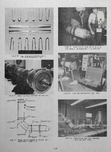
Design Engineering initiated instructions that pro vided the guidelines for investigating a welding procedure for the repair welding of crawler/trans porter shoes. By use of the isothermal transfor mation diagram, a range of preheat was established at 300°F to 500°F. Immediately after the comple tion of welding, the repaired shoe was raised in temperature to 600 ± 50°F, and maintained at this temperature for a minimum of two hours, then cool ed at the rate of 100°F per hour to a temperature of 200°F after which it was cooled to ambient temperature with no further monitoring. The latter, postheat treatment was performed to diffuse out hydrogen that had been inducted by welding. The preheat and postheat control for welding was main tained by use of electrical resistance heating ele ments in a specially designed heat treatment oven shown in Figure 7. Electrical timers permitted the control of preheating overnight so that weld ing could begin at the start of the day shift. An AWS E-14018 type of self consuming welding elec trode was applied to perform the welding using the manual shielded metal arc welding process. This electrode was developed under a Navy contract for welding HY 130 steels used in constructing nuclear submarine/pressure hulls. This electrode produces weld metal of 140,000 psi tensile strength that
patched the mechanical properties of the cast steel base metal in the shoe.
Welding electrodes are received in hermetically sealed containers to assure that their hygroscopic coatings do not absorb hydrogen in the form of water vapor. Immediately after opening the container, electrodes must be placed in a holding oven main tained at 250°F. Small portable holding ovens are located at the welding site for individual dispens ing of electrodes. Each welder must not remove more than 20-minute supply of electrodes. Elec trodes exposed to the atmosphere for more than 20 minutes must be rebaked at 750° * 25°F for one hour in a vented forced air furnace with adequate temp erature control. Electrodes must be placed in a holding oven immediately after rebaking and not re- baked more than one time. Electrodes that come in to contact with grease, paint, water, or other con taminants must be discarded.
During the welding of quenched and tempered steels, the heat input must be carefully controlled to as sure that the metallurgical structure of the weld is not adversely affected. If the weld structure is adversely affected by an incorrect heat input, the reaction is not reversible by heat treatment, and cracking may result. To control the heat input during welding, it is necessary to monitor the weld ing amperage, the welding voltage and the welding travel speed. Because of the importance of energy input, it is monitored in conjunction with preheat during the welding of quenched and tempered steels. It is measured in watt seconds or Joules per inch. For convenience, a simple formula can be used, as given:
Energy Input = Amps x Volts x 60In. per Min (Weld Travel Speed)
The energy input limit is not as critical for thick sections as it is for thin sections. It was found not to pose a problem in the repair welding of the crawler shoes. To determine the affect of the welding parameters, including the preheating and postheating, trial welds were made and tested. The results of these tests showed that the properties of the weld metal and the weld fusion zone were good and the heat affected zone was acquiescent so that satisfactory mechanical properties were obtain ed. Welding in progress is shown in Figure 8. This procedure gave satisfactory results in the repair welding of crawler/transporter shoes. Results of weld metal mechanical property tests are shown in Table 5.
Three methods are used for inspecting shoes for cracks and other defects. They are the dye pene- trant inspection, magnetic particle inspection and radiographic or x-ray inspection methods. A shoe being prepared for radlographic inspection is shown in Figure 9 on the turn table of the 20 million volt betatron x-ray facility. The betatron is capable of penetrating 16 inches of steel. It was used ori ginally for x-raying solid rocket motors.
After the repair weld is built up on the roller path of a crawler shoe, the roller path is machined on a horizontal mill to its original contour
4-81
tolerances as 'shown in Figure 10*
Worn lug bores are repaired by press fitting sleeves into the lugs and reboring them to fit the pins. These sleeves are AISI 4340 steel of approximate 330 Bhn hardness. The addition of hard sleevesstrengthens the bore and increases its resistance to wear.
The pins that attach shoes together to form the belt are of AISI 4130 steel. At present a study is being considered to investigate the metal spraying of the pins to hard surface them,Finally the shoes are machined and ground aroundthe lug areas to assure that adequate tolerances exist for clearance of moving parts without bind ing during the operation of the crawler belt.
IRQPELLANTS..SYSTEM WELDING.
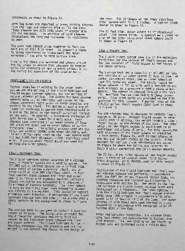
Typical examples of welding in the propel 1 ants system are the welding of the liquid hydrogen and liquid oxygen storage spheres, and the welding of vacuum jacketed piping. The plates for both storage spheres were cut to templates and dished to the •proper spherical radii prior to their erection and welding in the field. The design of each plate al lowed for shrinkage to permit each finished weld to blend at the joint to the overall spherical contour of the tank. In general, a transverse shrinkage of 3/32 inches was allowed for a weld seam* Each storage tank consisted of an inner sphere of Type 304 stainless steel and an outer sphere of carbon structural steel. The welding process used was gas metal arc welding (GNAW) with argon shielding gas. The weld filler metal used on the inner sphere weld ing was 0.045 inch diameter, E-308L stainless steel wire, A carbon steel filler metal was used for welding the outer sphere.
The liquid hydrogen system consists of a storagearea 9 a transfer system and a venting system. The 850,000 gallon storage sphere has a 70 foot diam.outer shell of carbon structural steel, and an inner shell of Type 304 stainless steel. A fourfoot annular space between the inner and outer shells is filled with expanded perlite (volcanic glass) insulation and evacuated to a pressure of50 microns of mercury absolute* The inner sphere is hung by stainless steel rods extending between the spheres at the equator. This design of support minimizes heat transfer. A photograph of the liquid hydrogen storage tank and some of its piping with a space vehicle in the background is shown in Figure 11,
The storage tank is designed to contain liquid hy drogen at 90 psig. The design also provides for the differential pressure resulting from the vacuum in the insulated space between the inner and outer spheres. The liquid hydrogen is low in density; consequently* its pressure and. not its weight is the controlling factor in the design of
the tank. The thickness of the inner stainless steel sphere wall is 1.16 inches. A typical joint design is shown in Figure 12.
The 70 foot diam. outer sphere is of structural steel 11/16 inches thick. A typical weld joint de sign of the outer structural steel sphere shellis shown in Figure 13.
L ...Oxygen Tank...
The liquid oxygen system consists of the necessary facilities for the storage of liquid oxygen and for the transfer of liquid oxygen to the stages of the space vehicle.
The storage tank has a capacity of 900,000 gallons and consists of an outer sphere 70 feet in diam. of carbon structural steel, and an inner sphere of Type 304 stainless steel. The annular space be tween spheres is filled with peri it insulation and with nitrogen at a pressure slightly above atmos pheric. The sphere is charged through a six inch fill manifold from self-unloading highway trans ports. Five inlet ports are provided on the fill manifold for this purpose. A partial view of the 900,000 gallon liquid oxygen (LOX) tank is shown in Figure 14.
The LOX storage tank is designed to contain liquid oxygen at 10 psig. Because liquid oxygen is rela tively high in density, its weight becomes a signi ficant factor in the design of the tank. The total weight of the liquid oxygen is equivalent to an additional calculated 30 psig. For this reason, the wall thickness of the inner sphere is graduated in four zones, Figure 15, with thinner plates at the top and thicker plates at the bottom. Joint designs for various plate thicknesses are shown in Figure 16 where the joints are referred to Table 6 which summarizes the joint design details.The 70 foot diam. outer sphere of the liquid oxygen tank is made of structural steel 11/16 inches thick. A typical joint design used for this vessel is shown in Figure 17.
Fabrication of the liquid hydrogen and liquid oxy gen storage spheres was performed in accordance with the ASME Boiler and Pressure Vessel Code, in cluding procedure and operator qualification in accordance with Section IX, The welds in the liq uid hydrogen and liquid oxygen storage tanks were radiographically inspected. The inner spheres of both the liquid hydrogen and liquid oxygen storage tanks were 1001 x-rayed in accordance with para graph UW 51 of Section VIII of the Code. The outer spheres of both tanks were spot checked by x-ray inspection in accordance with paragraph UW 52 of Section VIII of the Code.
After radiographic inspection, the storage tanks were leak tested and hydros tatlcally tested, then cold shocked. The leak testing of the liquid hy drogen tank was performed using a hell urn mass
4-81
spectrometer type of leak tester. The inner sphere was pressurized to 90 psig with a 20% helium-air mixture with a "full" vacuum in the annular space. The operating pressure for the liquid hydrogen inner sphere is 60 psig. The helium sensing pick up was located in the annular space during the test which permitted a maximum leak rate of 10~ 7 atmos pheric cubic centimeters per second. Subsequent to the helium leak testing, the inner sphere of the liquid hydrogen tank was hydro-pneumatically tested at 1% times the operating pressure. During the test, the inner sphere was partially filled with water to 1/16 capacity to simulate the weight of a full tank of liquid hydrogen. It was not possible to fill the tank full of water because the weight of a full tank of water would cause an excessive load on the inner tank supports and the column sup ports. Water is approximately 16 times heavier than liquid hydrogen. After hydro-pneumatic test ing, the liquid hydrogen storage tank was cold shock tested with liquid nitrogen.
The liquid oxygen tank was leak tested by pres surizing the inner sphere with nominal pressure of gaseous nitrogen and applying a soap bubble test to the weld areas. Subsequent to the leak test, the inner sphere of the liquid oxygen tank was hy- drostatically tested at 1% times the design pres- ure of 18 psig. After hydrostatic testing, the liquid oxygen storage tank was cold shock tested with liquid oxygen prior to being placed in service.
Welding Vacuum Jacketed Piping
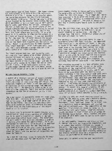
A sketch of a straight section of vacuum jacketed piping is shown in Figure 18. The inner pipe is Invar, an allow of iron containing 36% nickel. The principal property of invar is its low coefficient of expansion in the operating range from ambient to minus 423 F. By specifying Invar to be in con tact with the cryogenic fluid, the design engineer economizes on the use of expansion joints in the system.
The outer jacket is austenitic stainless steel pipe, AISI Type 304. Sections of VJ piping are fabrica ted in the shop. A minimum number of welds are made in the field. Sections are sometimes safe- ended with stainless steel to eliminate the need to weld Invar in the field because of the higher level of ski!"I required.
The inner pipe is procured in random lengths to a specification that covers seamless or welded pipe, but it is usually supplied as lengths of welded pipe made from rolled Invar sheet. The longitudi nal weld seam in this pipe can introduce a problem in making girth welds for spool pieces. It is ad vantageous to specifiy a filler metal of a modified chemistry described later for the longitudinal weld seam to minimize hot short cracking tendencies. The chemical composition of the Invar sheet is shown in Table 7 and the mechanical properties are shown in Table 8.
The 8 and 10 inch diam. sizes in Schedule 10 Invar pipe are the sizes used for the majority of the
cross-country piping in the propel!ants systems. The permissible variation in diameter is U.063 inches for this size range. The minimum wall thick ness accepted is 12.5% under the nominal wall thick ness specified. Ovality is maintained within 0.5% of the nominal diameter. The pipe is descaled but pickling in nitric-hydrofluoric acid is not per mitted.
Type 304 stainless steel pipe for the outer jacket of VJ piping is procured to ASTM-A-312, which covers seamless or welded pipe. The pipe is pickled free from scale. Mechanical properties of the pipe are shown in Table 9.
The welding of vacuum jacketed piping is done in accordance with a KSC specification. An important item specified in the welding of Invar is the use of Invar filler metal of modified chemistry. Past experience at the Kennedy Space Center has shown that Invar can be hot short and can crack in the weld under some conditions of heat input and stress. A particular example was noted during the fabrica tion of girth welds in Invar pipe for the original Apollo ground support equipment. A crack some times occurred when the girth weld traversed the existing longitudinal seam weld in the Invar pipe.
This cracking occurred in the heat-affected zone of the girth weld and was located in the grain structure of the longitudinal seam weld. The cracking was intergranular in nature, and it was found to be associated with low melting point phases existing in the longitudinal seam weld grain structure. The condition was more pronounced when the longitudinal seam weld had been made with lit tle or no filler metal added. The longitudinal seam may or may not have been planished after welding. Planishing obliterated any appearance of a seam and served to compound the problem by adding stress. To repair this type of cracking, it was found necessary to remove a portion of the longi tudinal seam weld and reweld it, using a modified Invar filler metal before completing the girth weld.
To alleviate this hot short cracking condition caused by low melting point, grain boundary phases, a filler metal of modified Invar chemistry was developed. This "modified" Invar filler metal con tains additives such as manganese and titanium that act as maileablizers. The composition of the modified tiller metal, as shown in Table lu» is verified by mill certificate. Chemical analysis checks are made on Invar filler wire clippings at the Kennedy Space Center. Also, chemical analyses are made of weld metal pads to verify their speci fied chemistry.
In the weld puddle, manganese and titanium react to remove iron sulfides from grain boundaries, and with carbon they control nitrogen and oxygen in the melt. The experience at the Kennedy Space Center has been that the use of the modified Invar filler metal reduces hot short cracking tendencies and thereby improves Invar weld properties and en hances the performance of Invar welds.
Invar pipe is welded using the gas tungsten-arc
4-83
process with direct current, straight polarity. Thewelding current is limited to 70 A maximum to main tain a low rate of heat input to the base metal. The interpass temperature is limited to 2:50' F maxi mum. These limits are set to minimize any tendency toward hot short cracking. Argon gas is used as a shielding and purging gas, procured to MIL-A-18455* The girth welds In the 8 and 10 inch diam. pipe sizes are welded In two stringer passes. A con sumable insert, 1/8 inch size MIL-1-23413, Group E, Type MIL-82, Glass 1 is applied for the root pass* This insert is a nickel alloy of the following chemical composition (wt. %): 0*10 C, 2.50-3,50 Mn, 3.00 Fe, 0*015 S» 0.50 SI, 0.50 Cu, 67.0 Ml, 0.75 Ti, 18.0-22.0 Cr s. 2.0-3.0 Cb. .Notified Invar filler metal of the composition shown in Table 10 is used in the cover pass,
In the qualification of welding procedures. Invar pipe in the 8 and 10 Inch diam, sizes, Schedule TO is used as most representative of the propel 1 ant system pipe size-requirements. The qualification is performed in the presence of a welding inspector, To be approved for all positions of welding, the procedure is qualified in the horizontal fixed and . in the vertical fixed pipe positions. The Invar and the stainless steel pipe weld joint designs are shown in Figure 19.
Pipe sizing by metal removal is permitted if the wall thickness is not reduced more than 12.5%. Ex ternal alignment clamps may be used in the assem bly of the pipe for qualification tests during the fitting of the insert. The test coupon is shown in Figure 20 with the alignment clamps in place. After tack welding, the alignment clamps are re moved prior to welding the test piece in the hori zontal and vertical fixed positions.
The weld joint is cleaned by solvent cleaning using methyl ethyl ketone (MEK) followed by mechanical scraping and brushing with an austenitic stainless steel wire brush* The weld joint and two inches on each side of the weld joint are cleaned prior to welding. The welding rods and insert ring also must be clean. The welding inspector verifies the quality of cleaning and the preweld setup including pipe end preparations, alignment, groove dimensions and fitup tolerances of'the weld test joint.
The pipe is purged and backed up with argon gas flowing at 10 cfh for 30 minutes prior to welding. Welding is performed using a 1/16 to 3/32 inch diam 2% thoriated tungsten electrode, The torch shield ing gas is argon it a flow rate of 18 to 25 cfh.
Joints are inspected after each pass to assure that they are properly cleaned and free of defects. When welding in the horizontal fixed position, the weld beads are laid so as to overlap two inches at the bottom and at the apex. To keep the heat input low* stringer beads are used for all passes in all welds. After the completion of the test weld, the weld ripples are removed from the weld surface on the face and root by mechanical process to a sur face finish of 125 rms. The test welds In Invar pipe are inspected using dye penetrants for sur face cracks, then the welds are 1001 x-ray In
spected to determine if they meet the radiograph!c• acceptance standards specified.
After radiographic inspection, the Invar test welds are cut ..into specimens for tensile and bend tests and metallographlc examinations. The tensile test must give results equal to or better than the prop erties shown in Table 8. Typical tensile and bend test specimens are shown in Figure 21.
The welding of Invar to Type 304 stainless steel is qualified In the same manner as Invar to Invar joints, except that the filler metal specified for the cover pass is a nickel alloy, MIL-E-21562,' Class 2, Type MIL-RN-82,
The welding of Type 304 stainless steel pipe for the outer jacket is qualified with the joint designshown In Figure 19, using Type 308 filler metal. The qualification test procedure requirements aresimilar to those required for fillet welds. The horizontal fixed and vertical fixed test joints combined qualify the procedure for all positionwelding.
It Is apparent that Invar has some tendency to de velop hot cracks that may go undetected. During the installation of the ground support equipment for the Apollo program, a test was devised to de- temrine If existing cracks present in Invar welds would propagate under cyclic cold shock. A mock- yp consisting of a section of VJ pipe was manufac tured. Figure 22. This mockup contained duplicate Invar-to-invar pipe welds and duplicate Invar to stainless steel pipe welds in 8 inch diam. piping. Certain designated welds were defect-free and others contained "built-in" cracks and other de fects.
One hundred cold shock cycles were applied to the mockup using liquid nitrogen as the shocking fluid. Accurate measurement of crack lengths were made be fore, during, and after completion of the testing. Examination revealed that no new cracks developed and that existing cracks did not propagate during cold shock testing. The fact that cracks did not propagate is attributed to the low coefficient of expansion of Invar and the thin wall of the 8 inch Schedule 10 pipe. The thermal stress is corres pondingly low. these results increased the level of confidence in the Invar welds and indicated that long time cryogenic service would be satisfactory.
Techniques for fabricating vacuum jacketed piping have been developed at KSC over the span of years since this piping was first introduced into theearly launch sites. Current design practice is tospecify the reuse of materials that exist in spool pieces and lines available on the launch complexwhen modifying systems to reconfigure for new pro grams,
A sketch from a typical design calling for the re configuration of an existing spool piece to a new shape reusing the materials in the existing spool piece is shown in Figure 23. This sketch shows a sequence of welding, numerically called-out, step by step, to facilitate the reassembly welding to
4-84

the new design configuration. Working to such de sign "road maps" 9 the shop has adopted techniques of cutting into existing spool pieces or lines to be modified, disassembling them into basic compo nents, which then are reassembled into new config urations. This has evolved into a unique capability for designing, fabricating and installing VJ lines of various shapes and sizes.
When an existing section of VJ piping is to be re configured to a new design, it is first disassem bled by cutting it into appropriate parts. This may be a single cut dividing it in two or it may be multiple cuts separating it into several sec tions as required by the new design. The cutting can be done using an abrasive cutting wheel or a portable saw or by using a dry running band saw. The outer jacket can be cut while the inner pipe remains intact, if desired, by restricting the depth of the cut.
Disassembly can be accomplished in the field, al though it is preferable to bring the pipe section into the shop. Care must be exercised to avoid cutting into existing teflon spacers or getter material in the annulus. During the disassembly, the aluminum foil or aluminum mylar insulation near the saw cuts becomes frayed and contaminated with particles, and it must be cut back several inches with a sharp knife before replacement during the reassembly operation. If the outer jacket is re moved from a section of VJ pipe, the aluminum in sulation may be unwrapped from the inner pipe and stored on a commercially clean spool that is then sealed in a polyethylene bag for reuse during re assembly.
The first step in the reassembly procedures is to prepare the inner pipe for butt welding by milling bevels on the pipe ends. The inner pipe is Invar in most cases, but in some lines, it is Type 304 stainless steel. A specially fabricated internal plug and external ring clamp are installed to main tain the thin walled pipe end circular during ma chining until the pipe is tack welded to an ad joining section to facilitate the fitting opera tion. Welding is performed by applying the ap proved procedures previously described for the girth butt welding of Invar pipe.
A section of VJ piping is shown in Figure 24 during an early stage of its reassembly. An oxygen analy zer is being applied to check the oxygen content of the purged inner pipe during a welding operation. This instrument is used as an adjunct to the quali fied procedure in the welding of Invar pipe. Al though not a requirement, an oxygen content of 1% or lower is considered to be good practice in the production of welds of satisfactory quality.
All welds in the inner pipe are 100% radiographi- cally inspected. The x-rays are made using a con tact shot technique. Six exposures are made around the circumference of the 8 inch diam. inner pipe. The 100 kV x-ray equipment used is portable. It is mounted on a two wheeled cart similar to the type used for portable single unit oxyacetylene outfits. Radiographs were made of the Invar pipe welds using 90 kV, 8mA, and 1% min exposures.
In addition to radiographic inspection, each weld is leak-tested using a helium mass spectrometer. The inner pipe containing the weld to be tested is sealed by applying aluminum plates against rubber gaskets coated with vacuum grease to each end of the pipe and evacuating the section as shown in Figure 25. A clear plastic hose coming from the vacuum pump on the leak tester is attached to a fitting in one of the aluminum plates. The inner pipe is evacuated to 50 microns.- Helium gas is applied to the external face of the weld by means of a nozzle and hose attached to a bbttle of helium gas. The leakage tolerance permitted at the weld is 10~9 standard (atmospheric) cubic centimeters per second of helium gas detection.
The weld is cleaned, and oxidation is removed using an austenitic stainless steel wire brush. Grease, oil and dirt, if present, are removed from the completed weld and pipe using Freon and a clean cloth.
The next step in the reassembly operation is the application of the insulation in areas where it h§d been removed during the disassembly. Because cleanliness is important, fabrication personnel are required to wear neoprene gloves. The insulation is trimmed back two inches on each side of the weld using a sharp clean knife or a razor blade. The trim line is then tapered from the surface of the pipe to the last layer of insulation for an addi tional two inches on each side of the weld, creat ing a beveled channel eight inches wide into which new insulation is applied. Aluminum foil insula tion is applied by wrapping the first layer 30 deg to the right of vertical, and the second layer 30 deg to the left of vertical and continuing with alternate layers until the newly applied insulation is level with the existing insulation.
Teflon block spacers mounted in stainless steel straps are installed over the aluminum foil insula tion at intervals to provide uniform spacing be tween the inner and outer pipes.
Next the outer jacket is fitted over the teflon spacers to mate with existing jacket ends. Sec tions of the outer pipe or jacket are joined by fillet welding a strap or sleeve slipped over the pipe ends, as shown schematically in Figure 23. This technique permits fitting and welding the jacket without the necessity for close tolerances in each length as required when butt welding. The welds in the outer jacket are 100% dye penetrant inspected.
After the completion of the welding of the outer jacket, a helium mass spectrometer vacuum leak test is conducted on the annulus similar to the one conducted on the inner pipe Invar welds. No leak detection of helium is allowed using a sensi tivity of 10-9 SCC/second.
After the completion of the helium mass, spectro meter vacuum leak test, a hydrostatic proof test of the inner line is conducted at \h times the working pressure of the cryogenic line.
4-85
A cold shock test is performed by flowing liquid nitrogen through the inner pipe of the completedspool piece as shown in Figure 26, During the initial stages, a vapor discharges from the vent line. Cold flow is continued until liquid nitrogen is observed coming from the discharge end of the transfer line. The level of the vacuum in the an nular space is recorded. The pressure must be less than 500 microns at this stage of fabrication.
The inner pipe of the spool piece is then cleaned in the cleaning facility In accordance with KSC specifications,, A sequence of trlchorethylene degreaslng and phosphoric acid cleaning proceduresare used.
After the spool piece has returned to ambient temp erature, a hot gaseous nitrogen purge is applied to the annul us. Gaseous nitrogen at 180 F and 5 psig is flowed through the annulur space for 20' h to dry it out*
A final vacuum puvnpdown is applied to the annul us. During this step, hot gaseous nitrogen at 180 F and 10 psig is flowed through the inner pipe to pro vide a heat source for enhancing the vacuum pump- down. The annul us is evacuated to 10 microns of •mercury absolute pressure and sealed by closing the VJ pipe vacuum port valves. The hot gaseous nitrogen flow is terminated, A vacuum decay test is conducted. Absolute.pressure in the annulus must measure below 10 microns of mercury after a 72 hour holding period.
Finally, all VJ pipe ports and end flanges are sealed using polyethylene sheet and bags until the spool piece is installed in the system. A positive purge pressure of gaseous nitrogen is maintained in the inner pipe during storage.
A heat loss determination has been made on fabri cated spool pieces. This consists of flowing liquid nitrogen through the inner pipe whilemeasuring heat loss by means of a heat loss sensor(calorimeter) attached to the outer jacket.
Vacuum jacketed piping was installed on the mobile launchers and on launch pads 39A and 39B for theApollo/Saturn program. A view of a straight run of cross country VJ pipine is shown in Figure 27extending from the liquid hydrogen storage tank to the launch pad on 39A and up the mobile launcherto the several swing arms servicing the space ve hicle. The line branching off at approximately midway to the pad is a section of the hydrogen vent line that returns hydrogen gas boiled off from venting the space vehicle liquid hydrogen tanks during fueling. This goes to a hydrogen burn pond.
Liquid hydrogen and liquid oxygen piping installed at the base of a mobile launcher is shown in Figure 28. The liquid hydrogen lines are the three larger lines at the left hand center of the photo graphs running horizontally to the center and up the mobile launcher. The middle line is the liquid hydrogen fill line. The bottom line is the line that vents the fuel tanks of the space vehic les second and third stages. The top line is the
vent from a helium heat exchanger wherein helium is cooled prior to pressurizing the space vehicle tanks for launch.
The liquid oxygen lines run in a configuration similar to the liquid hydrogen lines but are located on the mobile launcher at the right hand center of the photograph. The middle line is the 14 inch liquid oxygen fill line. The top line is the tank replenishing or topping^off line. The bottom line is the liquid oxygen tank vent line which goes to a dump basin on the pad where the vented liquid oxygen is disposed of by boiling it off to the atmosphere. A portion of the astronaut emergency egress chute can be seen at the right side of the photograph.
After several years of service during the Apollo/ Saturn program, a modification was made to the VJ piping in the liquid hydrogen storage sphere fill line on launch pad 39B. This modification was necessary to avoid the recurrence of fatigue failures in expansion bellows in the outer jackets of the Vj piping in the liquid hydrogen transfer lines. A failure that is typical of the fatique cracking experienced is shown in Figure 29. The design modification consisted of removing this type of expansion bellows from the system and re placing it with a new design using a larger con- volate in the bellows. Whenever possible, the welding had to be done in the shop.
However, much of the welding had to be done in the field. For field welding, either a tarpaulin or plastic screen is set up to shield the weld from the wind. A weld being made in the overhead posi tion with limited accessibility is shown in Figure 30.
The welds in the inner pipe were 100% radiograph- ically inspected. An inner pipe weld being radio- graphically inspected in the field is shown in Figure 31. The isotope source is mounted on a tripod and focused on the weld at the proper focal distance. The film in a black cassette is taped to the back side of the weld. A penetrameter can be seen taped to the near side of the weld. The lead box container with part of the remote control cable and radiation counters are in the foreground. While this type of radiograph is being made, the immediate area is roped off and monitored by the Safety Office to protect personnel from hazardous radiation. Upon completion of the exposure time, the isotope is remotely cranked back into the lead container by the inspector, who then retrieves the exposed film for development and viewing. The welds in the outer jacket are inspected using dye penetrants.
After radiographic testing is completed, the welds are helium mass spectrometer vacuum leak tested in the field. Next, the system is hydrostatically tested at 1% times the working pressure, cleaned, and then tested in an initial cold flow test prior to service.-
Another application of a weld, repair occurred when it became necessary to replace a damaged spool
4-86

piece in the liquid oxygen VJ piping on pad A. The spool piece was brought into the shop so that the damaged section of the inner pipe could be replaced. The damaged section was sawed out. A close view of the damage is shown in Figure 32. This crack was due to inadvertantly applying nitric acid in stead of phosphoric acid during a pipe cleaning operation on the spool piece. The reduction of wall thickness in the vicinity of the crack result ing from the action of the nitric acid on the Invar pipe was visually apparent ii? a cross section. A new section of Invar pipe was welded into the spool piece in the shop, and, after inspection, the unit was hydrostatically tested. The spool piece is shown in Figure 33 undergoing a final machining operation while being vacuum leak tested with a helium mass spectrometer leak tester. Finally, the repaired spool piece was reinstalled in the pro- pellants piping system.
To change from the Apollo/Saturn to the Skylab program, one mobile launcher was reconfigured to accommodate an S-IB type of launch vehicle. This required a modification to the liquid oxygen VJ lines on this mobile launcher. Existing VJ pipe sections and spare spool pieces were used to the maximum extent practicable in this modification. They were cut and reassembled in the shop to the modified configurations using the fabrication techniques previously described. Much of the work on individual sections was done in the shop. Com pleted sections and spool pieces were delivered to the Vehicle Assembly Building where they were in stalled on the mobile launcher undergoing modifica tions. Welding on this installation is shown in Figure 34, with safety nets and scaffolding deployedat weld stations. For this modification, it was re quired to maintain the interpass temperature below 150 F for certain welds. A welding inspector is shown in Figure 35 checking the interpass tempera ture of a weld on vacuum jacketed piping with a portable hand pyrometer.
Some areas on the mobile launcher are extremely limited in accessibility. One such area on an ele vated platform on the mobile launcher is shown in Figure 36. Flanged fittings welded to VJ piping can be seen where a portion of the outer jacket has been removed temporarily to provide access for welding.
All welds on the inner pipe where sections of VJ pipe were joined together at the weld stations on the mobile launcher were 100% radiographically in spected in the field. A weld marked for radio- graphic inspection is shown in Figure 37. After the completion of welding on the modified liquid oxygen system, the sytem was hydrostatically tested and cold shock tested prior to putting the system into service for the Skylab program.
Some development work has been done on the automatic welding of vacuum jacketed piping at the Kennedy Space Center. A vacuum jacketed spool piece being fabricated in the shop using an automatic pipe welding process is shown in Figure 38. This and other piping such as piping for the hydraulic steering mechanism on the transporter/crawler have
been fabricated using an automatic welding process. However, due to the variety of the welding encount ered, the more versatile manual welding takes pre cedence over automatic setups, which are better adapted to a more routine production line type of welding.
SUMMARY
Over the years spanning the implementation and growth of the space program, the Kennedy Space Center has developed a unique capability to design and fabricate ground support equipment. This has resulted in advancing the industrial technology in a number of areas including the area of welding technology. Welding specifications are establish ed for ground support equipment and welding proce dures have been qualified and proven for numerous applications, too voluminous to include in a single paper.
The applications described represent an attempt to provide some depth of coverage to the descrip tion of the welding of ground support equipment. However, the preponderance of additional material available must be omitted due to a limitation in writing space.
The welding technology developed during the Mercury, Gemini, Apollo, unmanned launches, and other programs is now being applied to design and fabricate the ground support equipment and facil ities required for the Space Shuttle.
REFERENCES
(1) Clautice, W. E., "Welding at the Kennedy Space Center," Welding Journal, Vol. 52 (6) June, 1973, pp 364-371.
(2) Clautice, W. E., "Brazing at the Kennedy Space Center", Welding Journal, Vol. 53 (10) October, 1974, pp 612-622.
(3) Clautice, W, E., "Welding Vacuum Jacketed Piping at the Kennedy Space Center", Welding Jour nal, Vol. 54 (7) July, 1975.
ILLUSTRATIONS
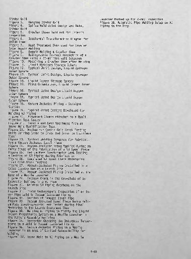
Table 1. KSC Welding SpecificationsTable 2. Linear Inches of Welds used on G-14Table 3. Composition of ShoesTable 4. Mechanical Properties of ShoesTable 5. Weld Mechanical PropertiesTable 6. Plate Orientation Data Liquid Oxygen Inner SphereTable 7. Chemical Composition of Invar Sheet Table 8. Mechanical Properties of Invar Sheet Table 9. Mechanical Properties of Type 304 Stain less Steel PipeTable 10. Modified Invar Filler Metal CompositionFigure 1. Orientation of Girder G-14 in the Mobile LauncherFigure 2. Field Assembly Welding Sequence of
4-87
Crawler Shoes laid out for Interim
Isothermal Transformation Diagram for
Girder G-14Figure 3* Hanging Girder 6*14 Figure 4* Splice Weld. Joint Design and Data, Girder 6-14 Figure 5, Inspection Figure 6. 86B30 SteelFigure 7* Heat Treatment Oven used for Crawler Shoe Repair WeldingFigure 8. Repair Welding a Crawler Shoe Figure 9. Radiographic (x-ray) Inspection of a Crawler Shoe using a 20-million volt Betatron Figure 10. Machining a Crawler Shoe after Welding Figure 11. Liquid Hydrogen Storage Sphere Figure 12. Typical Joint Design, Liquid Hydrogen Inner SphereFigure 13. Typical Joint Design, Liquid Hydrogen Outer SphereFigure 14. Liquid Oxygen Storage Sphere Figure 15. Plate Orientation, Liquid Oxygen Inner SphereFigure 16. Typical Joint Design Liquid Oxygen Inner SphereFigure 17. Typical Joint Design Liquid Oxygen Outer SphereFigure 18. Vacuum Jacketed Piping - Straight SectionFigure 19. Typical Joint Designs Developed for Welding VJ PipingFigure 20. Alignment Clamps attached to a Quali fication Test CouponFigure 21. Tensile and Bend Specimens from an Invar Weld Qualification Test Figure 22. Mockup for Cyclic Cold Shock Testing Welds Joining Invar to Invar and Invar to Stainless SteelFigure 23. Typical Welding Sequence for Fabricat ing a Vacuum Jacketed Spool Piece Figure 24. Oxygen Analyzer being Applied during an Early Stage of the Fabrication of a VJ Spool Piece Figure 25. Helium Mass Spectrometer Leak Testing a Section of VJ Piping during Fabrication Figure 26. Completed VJ Spool Piece Undergoing Final Cold Shock TestingFigure 27. Vacuum Jacketed Piping Installed in a Cross Country Run at a Launch Site Figure 28. Vacuum Jacketed Piping Installed at the Base of a Mobile LauncherFigure 29. Fatigue Crack in the Convolute of an Expansion Bellows in a VJ Pipe Figure 30. Welding VJ Piping Overhead on the Launch SiteFigure 31. Field Radiographic Inspection of an In var Pipe Weld in Vacuum Jacketed Piping Figure 32. Section of Damaged Invar Pipe Figure 33. Vacuum Jacketed Spool Piece Being Heli um Mass Spectrographic Leak Tested during Final Machining in the Launch Equipment Shop Figure 34. Welding VJ Piping to Modify the Liquid Oxygen Propel 1 ants System on a Mobile Launcher in the Vehicle Assembly BuildingFigure 35. Inspector Checking the Interpass Temper ature on a Weld in Vacuum Jacketed Piping Figure 36. Vacuum Jacketed Piping on a Mobile Launcher in an area of Limited Accessibility for Welding Figure 37* Invar Weld in VJ Piping on a Mobile
Launcher Marked up for X-ray Inspection Figure 38. Automatic Pipe Welding Setup on VJ Piping in the Shop
4-88

KSC-SPEC-Z-0001
KSC-SPEC-Z-0002
KSC-SPEC-Z-0003
KSC-SPEC-Z-0004
KSC-SPEC-Z-0005
KSC-SPEC-Z-0006
KSC-SPEC-Z-0010
KSC-SPEC-Z-0016
TABLE 1 - KSC WELDING SPECIFICATIONS
Invar Pipe, Specification
Welding, Aluminum Alloy Pipe, Tubing and Associated Fittings, Specification
Welding, Stainless Steel and Invar Pipe, and Associated Fittings, Specification
Welding, Structural, Carbon Steel, Stainless Steel, Low Alloy Steel, and Aluminum Alloys, Specification
Brazing, Steel, Copper, Aluminum, Nickel and Magnesium Alloys, Specification
Induction Brazing, Aerospace Tubing Fittings, Specification
Welding, High Yield Strength, Quenched and Tempered Alloy Steels, Specification
Automatic Welding, Stainless Steel Pipe and Tubing, Invar 36 Pipe, Carbon Steel Pipe, Aluminum Pipe, Specification
AWS D 1.1 Structural Welding Code
AWS A2.0 ,. Welding Symbols Standard
AWS A3.0 Welding Definitions
ASME Boiler and Pressure Vessel Code
ANSI B31.1 Pressure Piping Code
AISC Manual for Steel Construction
KSC Safety Manual
TABLE 2 LINEAR INCHES OF WELDS USED ON G-14
SUMMARY OF WELD LENGTHS
LENGTH TYPE (INCHES)
TOTAL FILLET WELDS 61,966 TOTAL SINGLE GROOVE WELDS 6,867 TOTAL DOUBLE GROOVE WELDS 7.421
TOTAL WELDS IN G-14 76,254
FILLET WELDS SINGLE GROOVE WELDS DOUBLE GROOVE WELDS
S V X /\
SIZE SIZE (INCHES) LENGTH (INCHES)
(FILLET LEG) (INCHES) (DEPTH OF CROSS SECTION)
1/4 6,834 1/2 3/8 4,055 3/4 1/2 13,841 11/16 5/16 33,482 7/8 3/4 3,554 1 1 200 1.1/2
3 TOTAL: 61,966 3.3/4
6
\y
LENGTH (INCHES) SIZE
(INCHES) 411 (DEPTH OF CROSS SECTION) 92 60 1/2 24 5/8
2,270 3/4 2,400 1
61 1-1 4 453
1,096 TOTAL:
LENGTH (INCHES)
72 52
1,721 1,608 3,968
7,421
TOTAL: 6,867
4-89

__. Table _L ... -
Element ' ' ' 'Carbon
Phosphorous *8ulfu* - * * * Siliconmotel <•' ' Hfelybdenui
* Boron
1 Composition' of Shoe's' Wt/ Percent
§,lf to *033 - 1*00 to 1*30 0*043 lux, 0*043 Max, " , - 0*80 to 0.3B'. " • 0*50 to 0*80 §,*•.§§ to 0»BO * 0*85 to 0.35 ,* 0.0005 Min*- v> •
fable" 5 -
Table 4 'Mechanical Propert '±&e of Shoes
Tensile Strength Yield Strength Elongation Reduction of Area Impact Strength
5
Hardness
130,000 psi100,000 psi12%25%15 ft lbs,Charpy V-
Notch at -400F 285* to 331 Bhii
Welfl MtfgBafrrcaT. Fropert ies
' PtfelteVt'
300-400°F :
400-500°F
S1:ret^|K BRSl' rreh'siTe' ' '
136,000
135,500
Strength, PSIYield
118,000
117,000
TABLE 6 - PLATE ORIENTATION DATA LIQUID OXYGEN INNER SPHERE
PLATE LOCATION
Top
Top toMiddle
Middle
Middle toEquator
Equator
Equator toHi) (lorn
Bottom
DESIGN LOAD
Retains 10 psig pressure
_
Retains 10 psig plus1/2 pressure of900,000 gallons LOX,30/2 or 1 5 psig
_
This is the .area ofattachment forstructural loading.These plates takethe reaction forcesfor the entire loadso are the heaviest.
_
Retains 10 psig + 30psig pr,.v , .:."„• due tototal weight of 900,000gallons LOX or 40 psig*
EQUIVALENT PRESSURE
(PSIG) j10
. _
25t
_
N/ALoad basedupon reactionforces.
_
40
KM/m*>68.95x1 03
17.24% 104
27.58x1 04
PLATE THICKNESS
(INCHES)
0.250
0.250 to0.380
0.380
0.380 to0.538
0..538
0.538 to•0.425
0,425
METERS
6.35xlO-2
9.65x1 0-2
1 3.67xlO-2
10.79xlO"2
JOINT DESIGN (See Figure 12)
A
Transition A to B
B ;
Ira nsi t ion B to C
C 1
See Note (a) j
C
NOTE: fa) The transition joint design for joining equator plates to bottom plates is the same as the transition joint design B to C 4'-r joining middle piites to equator plates; that is, a double beveled scarf with 3 to 12 ratio reduction of the thicker piute*
4-90
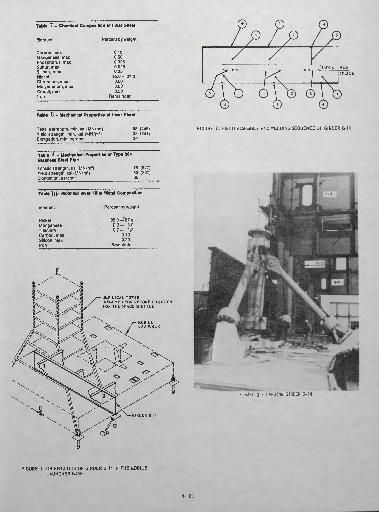
Table 7 — Chemical Composition of Invar Sheet
Elements
Carbon, max Manganese, max Phosphorus, max Sulfur, max Silicon, max NickelChromium, max Molybdenum, mux Cobalt, max Iron
Percent by weight
0.10 0.50 0.025 0.025 0.35
35.0-37.00.500.500.50
Remainder
Tabfc o - Mechanical Properties of Invar Sheeto
SPLICE
Tensile strength, min, ksi (MN/m 2 ) Yield strength, mln, ksi (MN/m z ) Elongation, mln, percent
65 (448) 35 (241) 30
FIGURE 2: FIELD ASSEMBLY AND WELDING SEQUENCE OF GIRDER G-14
Table 9 - Mechanical Properties of Type 304 Stainless Steel Pipe
Tensile strength, ksi (MN/m2 ) Yield strength, ksi (MN/m2 ) Elongation, percent
75 (517) 30 (207) 35
Table ] 0- Modified Irwar Filler "Mtlal Composition
Element Percent by weight
NickelManganese TitaniumCarbon, maxSilicon, maxIron
35.0-37.U2.0- 3.0 0.7- 1.2
0.100.20
Remainder
UMBILICAL TOWER(REMOVED FOR RECONFIGURATIONFOR THE SPACE SHUTTLE)
FIGURE 3 - HANGING GIRDER G-14
GIRDER G-U
FIGURE 1 ORIENTATION OF GIRDER G-14 IN THE MOBILE LAUNCHER BASE
4-91

C-0.30 Mn-0.80Nl-0.54 Cr-0.55
Mo-0.21
Austenitized ot 1600°F Grain Size; 9
LEGEND
SUBMERGED ARC WELDINGPREQUALiFIED JOINT DESIGN B-LJ2-S (AWS DU)S/64" DIA, WIRE, FLUX, 33 VOLTS,450 AMPS AND 12"/MIN TRAVEL SPEED FOR ALL PASSES.PREHEAT 200 F.
C-CarfeUi* f»NoiB»»
FIGURE 6 - ISOTHERMAL TRANSFORMATION DIAGRAM FOR 86B30 STEEL (U.S. STEEL ATLAS)
FIGURE 4- WELDING DATA AND JOINT DESIGN FOR THE FLANGE SPLICE WELDS
FTRllRF 5 . CRAWLER SHOES LAID OUT FOR INTERIM INSPECTION FIGURE 7 - l^EAT TRtIA
4-92
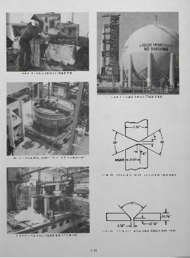
FIGURE 8 - REPAIR WELDING A CRAWLER SHOE
FIGURE 9 - RADIOGRAPHIC (X-RAY) INSPECTION OF A CRAWLER SHOE
LIQUID HYDROUSNO
FIGURE 11 - LIQUID HYDROGEN STORAGE SPHERE
FI-3URE "12 - TYPICAL JOINT DESIGN LIQUID HYDROGEN INNER SPHERE
°-\
>v
f
FIGURE 10 - MACHINING A CRAWLER SHOE AFTER WELDING
5/32" •FIGURE 13 - TYPICAL .iniNT DESIGN LIQUID HYDROGEN OUTER SPHERE
4-93

i I illFIGURE 14 - LIQUID C;;YGC,; STORAGE SPHERE
'EQUATOR
JOINT A12
TRANSITION JOINT A TO B
-45*
-H H— 18"JOINT B
12
5/32"
Transition Joint B to C
-45°
'V̂--45
Joint CFIGURE 16 - TYPICAL JOINT DESIGNS LIQUID OXYGEN INNER SPHERE
45°
INSiPE SPHERE £L£VATiCN
FIGURE 15 - PLATE ORIENTATION ELEVATION* LIQUID OXYGEN INNER SPHERE
1
7/32"—J ^ [——5/32"
FIGURE 17 - TYPICAL JOINT DESIGN LIQUID OXYGEN OUTER SPHERE
4-94

INVAR TYP.
NOTES:
1. THE INNER PIPE IS INVAR CONFORMING TO KSC.SPEC.Z.OOOl, 6 INCH, SCHEDULE 5
(0.109" WALL THICKNESS)2. THE OUTER JACKET IS STAINLESS STEEL PIPE, AISI TYPE 304, 8 INCH, SCHEDULE 5,
ASTM A312.3. WELDING IS AS SPECIFIED IN KSC-SPEC-Z-0003.
4. STAINLESS STEEL END CAPS ARE REMOVED AFTER LEAK TESTING AND HYDROSTATIC TESTING.
5. THE ANNULUS IS MAINTAINED AT 50 MICRONS OF MERCURY ABSOLUTE PRESSURE TO INSULATE THE
INNER PIPE CONTAINING CRYOGENIC FLUID FROM CONDUCTING AND CONVECTION HEAT FLOW FROM
THE ATMOSPHERE AT AMBIENT TEMPERATURE.6. THE INNER PIPE IS INSULATED FROM RADIANT HEAT BY ALUMINUM FOIL, ALUMINZED MYLAR OR
SIMILAR MATERIAL WRAPPED AROUND THE 0 D. OF THE IN V AR PIPE. TEFLON SPACERS ON STAINLESS
STEEL STRAPS ARE USED TO POSITION THE INNER PIPE CONCENTRICALLY FROM THE OUTER PIPE.
7. GETTER MATERIAL IS INSTALLED IN THE ANNULUS TO ALLEVIATE OUTGASSING.
FIGURE 18- VACUUM JACKETED PIPING - STRAIGHT SECTION
*55
I——.025"'.005"
INNER PIPE - INVAR BUTT WELD JOINT DESIGN
AISI TYPE 304 BAND
X7
AISI TYPE 304 OUTER JACKET
OUTER JACKET - FILLET WELDS JOINING SECTIONS USING A STAINLESS STEEL BAND
FIGURE 19 - TYPICAL JOINT DESIGNS DEVELOPED FOR WELDING VJ PIPING
FIGURE 20 - ALIGNMENT CLAMPS ATTACHED TO A QUALIFICATION TEST COUPON
4-95
W w
'I•J
FIGURE ?1 - TfijfiJLJEAHD BEND SPECIMENS FROM AN IHVAft 1ELD QUALIFir.flTTnN TFST
FIGURE 22 - MOCKUP FOR CYCLIC COLD SHOCK TESTING WELDS
FIGURE 24- OXYGEN ANALYZER BEING APPLIED DURING AN EARLY STAGE OF THE FABRICATION OF A VJ SPOOL PIECE
FIGURE 21 - HELIUM MASS SPECTROGRAPHIC LEAK TESTING
WELD 4
FIGURE 23 - TYPICAL FOR FABRICATING AVACUUM JACKETED SPOOL PIECE
FIGURE 26 - COMPLETED VJ SPOOL PIECE UNDERGOING FINAL COLD SHOCK TESTING
4-98
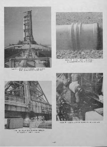
FIGURE 27 - VACUUM JACKETED PIPING INSTALLED IN A CROSS COUNTRY RUN AT A LAUNCH SITE
OF AN EXPANSION BELLOWS IN A VJ PIPE
FIGURE 30 - WELDING V. , *i'^ ,ALRHEAD OH THE LAUNCH SITE
FIGURE 28- VACUUM JACKETED PIPING INSTALLED AT THE BASE OF A MOBILE LAUNCHER
4-97

FIGURE 31 - FIELD' RADIOGRAPH 1C INSPECTION OF AN INVAR, PIPE HELD 111 VACUUM JACKETED PIPING
FIGURE 33. VACUUM JACKETED SPOOL PIECE BEING HELIUM MASS SipECTIROGiRAPHIC LEAK TESTED DURING FINAL MACHINING IN THE LAUNCH EQUIPMENT SHOP
FIGURE 34- WELDING VJ PIPING TO MODIFY THE LIQUID OXYGEf! PROPELLANTS SYSTEM ON A MOBILE LAUNCHER IN THE VEHICLEASSEMBLY BUILDING
FIGURE 32 - SECTION OF DAMAGED INVAR PIPE FIGURE 35 _ INSPECTOR CHECKING THE INTERPASS TEMPERATUR! ON A WELD IN VACUUM JACKETED PIPING
4-98
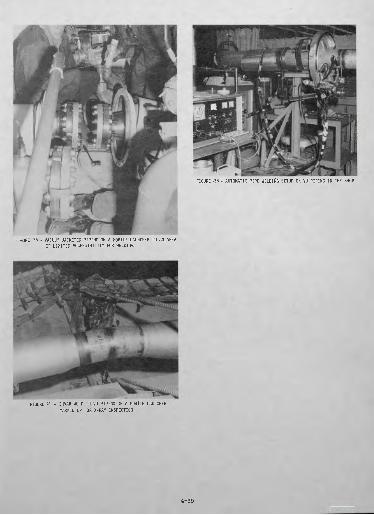
FIGURE '38 - AUTOMATIC PIPE WELDING SETUP ON VJ PIPING IN THE SHOP
FIGURE 36 - VACUUM JACKETED PIPING ON A MOBILE LAUNCHER IN AN AREA OF LIMITED ACCESSIBILITY FOR WELDING
FIGURE 37 - INVAR WELD IN VJ PIPING ON A MOBILE LAUNCHER MARKED UP FOR X-RAY INSPECTION
4-99