Embed Size (px)
Citation preview
Weld Seam
s in Alum
inium A
lloy Extrusions: Microstructure and Properties | A
ndrew Jam
es den Bakker
Weld Seams in Aluminium Alloy Extrusions: Microstructure and Properties
AndrewJamesdenBakker

Weld Seams in Aluminium Alloy Extrusions: Microstructure and Properties
PhD thesis
Andrew James den Bakker

Weld Seams in Aluminium Alloy Extrusions:
Microstructure and Properties
Proefschrift
ter verkrijging van de graad van doctor
aan de Technische Universiteit Delft,
op gezag van de Rector Magnificus prof.ir. K.C.A.M. Luyben,
voorzitter van het College voor Promoties,
in het openbaar te verdedigen op
woensdag 26 oktober 2016 om 15:00 uur
door
Andrew James DEN BAKKER
Master of Science in Materials Science and Engineering
TU Delft
geboren te Vlaardingen, Nederland
This dissertation has been approved by the
promotor: Prof. dr. ir. S. van der Zwaag
Composition of the doctoral committee:
Rector Magnificus Chairman
Prof. dr. ir. S. van der Zwaag Delft University of Technology
Prof. ir. L. Katgerman Delft University of Technology
Independent members:
Prof. dr. ir. J. Sietsma Delft University of Technology
Prof. dr. ir. R. Benedictus Delft University of Technology
Prof. dr. ir. R. Petrov Delft University of Technology
Prof. Dr. Ing. A.E. Tekkaya Technische Universität Dortmund
Prof. dr. W.Z. Misiolek Lehigh University
This research was partially carried out under project numbers MA10196, MA10217 and
MA10218 in the framework of the Research Programme of the Materials innovation
institute (www.m2i.nl)
This project was financially supported by Nedal Aluminium.
Further additional support was provided by Almax Mori Srl (Italy).
Keywords: extrusion; aluminium alloys; weld seams; mechanical properties; microstructure
Copyright @2016 by A.J. den Bakker
[email protected] / [email protected]
All rights reserved. No part of the material protected by this copyright notice may be
reproduced or utilised in any form or by any means, electronic or mechanical, including
photocopying, recording or by any information storage and retrieval system, without
permission from the author.
Cover design, lay out and typography by Maximum Koppel, www.maximum-koppel.nl
Printed in The Netherlands by Ipskamp Printing.
ISBN 978-94-028-0329-7
5
Tabl
e of
con
tent
s
Table of Contents
Chapter 1 Introduction .............................................................................................................................. 9
1.1 Background ................................................................................................................................ 10
1.2 Charge welds ............................................................................................................................. 10
1.3 Longitudinal weld seams ..................................................................................................... 12
1.4 Weld seam characterisation and imperfections ........................................................ 13
1.5 Scope and outline of this thesis ........................................................................................ 15
1.6 References .................................................................................................................................. 16
Chapter 2 Web filling in multi-port dies for extrusion of asymmetric,
double-hollow aluminium profiles. ................................................................................ 17
2.1 Introduction ............................................................................................................................... 18
2.2 Flow simulation ....................................................................................................................... 20
2.3 Experimental verification ..................................................................................................... 24
2.4 Results and discussion .......................................................................................................... 26
2.4.1 Material model ......................................................................................................................... 26
2.4.2 Modeling results ...................................................................................................................... 28
2.4.3 Experimental flow analysis ................................................................................................. 30
2.5 Effect of process conditions on material flow ............................................................. 30
2.6 Start-up section and dimensions ..................................................................................... 31
2.7 Material transition .................................................................................................................. 32
2.8 Local material flow ................................................................................................................. 34
2.9 Evolution of weld seams ...................................................................................................... 37
2.10 Discussion .................................................................................................................................. 38
2.11 Conclusions ................................................................................................................................ 40
2.12 References .................................................................................................................................. 40
Chapter 3 Analysis of the structure and resulting mechanical properties of
aluminium Extrusions containing a charge weld interface .................................. 43
3.1 Introduction ............................................................................................................................... 44
3.2 Experimental ............................................................................................................................. 45
3.2.1 Materials ..................................................................................................................................... 45
3.2.2 Extrusion shape and processing ....................................................................................... 45
3.2.3 Characterisation ...................................................................................................................... 48
3.3 Results .......................................................................................................................................... 49
3.3.1 Flow analysis / transition ..................................................................................................... 50
3.3.2 Resulting topology of the charge weld contour ......................................................... 51
3.3.3 Failure morphology ................................................................................................................ 53
3.3.4 Crack initiation and propagation stages ....................................................................... 54
3.3.5 Failure surface topology ....................................................................................................... 55
6
Tabl
e of
con
tent
s
3.3.6 Resulting mechanical properties and their relation to the crack evolution ... 58
3.4 Discussion .................................................................................................................................. 61
3.4.1 Tensile strength vs oxide particle distribution ............................................................ 61
3.4.2 Ductility ....................................................................................................................................... 64
3.5 Conclusions ................................................................................................................................ 66
3.6 References .................................................................................................................................. 67
Chapter 4 Microstructure and properties of longitudinal weld seams
in aluminium alloy extrusions .......................................................................................... 69
4.1 Introduction ............................................................................................................................... 70
4.2 Experimental ............................................................................................................................. 72
4.2.1 Materials ..................................................................................................................................... 72
4.2.2 Extrusion geometry and tooling ....................................................................................... 73
4.2.3 Extrusion processing .............................................................................................................. 75
4.3 Characterisation ...................................................................................................................... 77
4.3.1 Mechanical characterisation .............................................................................................. 77
4.3.2 Microstructural assessment ............................................................................................... 78
4.4 Results .......................................................................................................................................... 79
4.4.1 Charge weld length ................................................................................................................ 80
4.4.2 Aging response ......................................................................................................................... 81
4.4.3 Microstructure .......................................................................................................................... 82
4.4.4 EBSD analysis ............................................................................................................................ 86
4.4.5 Mechanical characterisation .............................................................................................. 92
4.4.5.1 Fracture toughness ................................................................................................................. 92
4.4.5.2 Tensile test results .................................................................................................................. 93
4.4.5.3 Localised strain measurements ........................................................................................ 94
4.5 Discussion .................................................................................................................................. 99
4.6 Conclusions ................................................................................................................................ 103
4.7 References .................................................................................................................................. 104
Chapter 5 Microstructural and X-ray tomographic analysis of damage in
extruded aluminium weld seams .................................................................................... 107
5.1 Introduction ............................................................................................................................... 108
5.2 Experimental ............................................................................................................................. 111
5.2.1 Materials preparation ............................................................................................................ 111
5.2.2 Extrusion experiments .......................................................................................................... 111
5.2.3 Materials characterisation .................................................................................................. 113
5.3 Results .......................................................................................................................................... 114
5.3.1 Microstructure analysis ........................................................................................................ 114
5.3.2 Mechanical performance ..................................................................................................... 116
5.3.3 Damage assessment.............................................................................................................. 117
5.4 Discussion .................................................................................................................................. 120
7
Tabl
e of
con
tent
s
5.5 Conclusions ................................................................................................................................ 123
5.6 References .................................................................................................................................. 124
Chapter 6 The origin of weld seam defects related to metal flow in the
hot extrusion of aluminium alloys EN AW-6060 and EN AW-6082 .................. 127
6.1 Introduction ............................................................................................................................... 128
6.2 Experimental ............................................................................................................................. 130
6.2.1 Materials ..................................................................................................................................... 130
6.2.2 Mechanical characterisation .............................................................................................. 131
6.2.3 Microstructural assessment ............................................................................................... 132
6.3 Modelling .................................................................................................................................... 133
6.4 Results .......................................................................................................................................... 134
6.4.1 Mechanical assessment ....................................................................................................... 134
6.4.2 Microstructural assessment ............................................................................................... 135
6.4.3 Modelling results..................................................................................................................... 139
6.5 Discussion .................................................................................................................................. 142
6.6 Conclusions ................................................................................................................................ 143
6.7 References .................................................................................................................................. 144
Summary ........................................................................................................................................................... 145
Samenvatting .................................................................................................................................................. 149
List of publications ........................................................................................................................................ 155
Acknowledgements ...................................................................................................................................... 159
Curriculum vitae ............................................................................................................................................. 163

CHAPTER 1
Introduction
Abstract
Extrusion is a well-established and powerful processing technique for the production of
aluminium products with constant cross-sectional dimensions. However, the understanding
of weld seam phenomena at billet change-over and in the longitudinal weld seams in hollow
products is far from complete. In this chapter some of the relevant issues are summarised, the
key challenges are identified and the scope of the thesis is presented.
10
Weld Seams in Aluminium Alloy Extrusions: Microstructure and PropertiesC
hap
ter 1
1.1 Background
In aluminium extrusion of hollow continuous products structural discontinuities such as
charge welds and longitudinal weld seams are formed which are inherent to the nature of
the process and the applied tooling configurations. These phenomena can have an impact
on the extrudate properties and can therefore affect the performance of structures in
which these extrusions are incorporated. In the following sections the most prominent
phenomena originating from the discontinuous nature of extrusion are introduced,
together with the impact of such discontinuities on product properties.
1.2 Charge welds
In commercial extrusion production billets are sequentially and quasi-continuously
processed in each extrusion cycle. Although at the end of each process cycle the butt discard
is removed, the die remains filled with the ‘old’ billet material. The changeover from the old
to the new billet results in a bond region, known as the charge weld transition. The charge
weld area forms as the initially planar contact surfaces of the billets are deformed analogous
to the metal flow inside the extrusion tooling. A transition area is then formed where the
cross section is gradually filled by the new billet. The boundaries between the old and new
billet material are called charge welds or transverse welds1. The ‘cusps’ extend inside the
profile over a certain length, depending on the profile shape and the die geometry. An
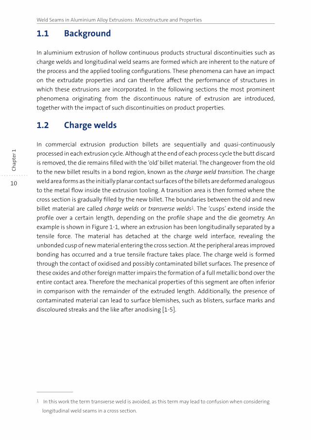
example is shown in Figure 1-1, where an extrusion has been longitudinally separated by a
tensile force. The material has detached at the charge weld interface, revealing the
unbonded cusp of new material entering the cross section. At the peripheral areas improved
bonding has occurred and a true tensile fracture takes place. The charge weld is formed
through the contact of oxidised and possibly contaminated billet surfaces. The presence of
these oxides and other foreign matter impairs the formation of a full metallic bond over the
entire contact area. Therefore the mechanical properties of this segment are often inferior
in comparison with the remainder of the extruded length. Additionally, the presence of
contaminated material can lead to surface blemishes, such as blisters, surface marks and
discoloured streaks and the like after anodising [1-5].
1 In this work the term transverse weld is avoided, as this term may lead to confusion when considering
longitudinal weld seams in a cross section.
11
Introduction
Ch
apte
r 1
Figure 1-1 Detail of an extrusion separated at the charge weld interface, revealing the
bulbous cusp of new material and shear lips at the peripheral, well bonded areas.
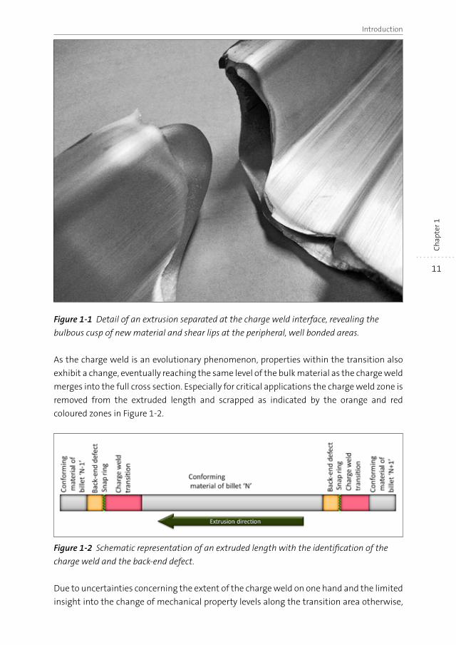
As the charge weld is an evolutionary phenomenon, properties within the transition also
exhibit a change, eventually reaching the same level of the bulk material as the charge weld
merges into the full cross section. Especially for critical applications the charge weld zone is
removed from the extruded length and scrapped as indicated by the orange and red
coloured zones in Figure 1-2.
Figure 1-2 Schematic representation of an extruded length with the identification of the
charge weld and the back-end defect.
Due to uncertainties concerning the extent of the charge weld on one hand and the limited
insight into the change of mechanical property levels along the transition area otherwise,
12
Weld Seams in Aluminium Alloy Extrusions: Microstructure and PropertiesC
hap
ter 1
the amount of material that is to be eliminated is often not well defined. Insufficient
elimination leaves a segment of the extruded length with remnants of the charge weld
transition, having inferior material properties. Over-estimation of the transition length
leads to erroneous scrapping of fully conforming material, impacting the economics of the
process.
1.3 Longitudinal weld seams
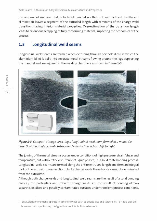
Longitudinal weld seams are formed when extruding through porthole dies2, in which the
aluminium billet is split into separate metal streams flowing around the legs supporting
the mandrel and are rejoined in the welding chambers as shown in Figure 1-3.
Figure 1-3 Composite image depicting a longitudinal weld seam formed in a model die
(insert) with a single central obstruction. Material flow is from left to right.
The joining of the metal streams occurs under conditions of high pressure, strain/shear and
temperature, but without the occurrence of liquid phases, i.e. a solid-state bonding process.
Longitudinal weld seams are formed along the entire extruded length and form an integral
part of the extrusion cross-section. Unlike charge welds these bonds cannot be eliminated
from the extrudate.
Although both charge welds and longitudinal weld seams are the result of a solid bonding
process, the particulars are different. Charge welds are the result of bonding of two
separate, oxidised and possibly contaminated surfaces under transient process conditions.
2 Equivalent phenomena operate in other die types such as bridge dies and spider dies. Porthole dies are
however the major tooling configuration used for hollow extrusions.
13
Introduction
Ch
apte
r 1
Longitudinal weld seams are the result of recombined metal streams originating from the
same billet, under exclusion of oxygen3 and essentially unchanging process conditions. The
processes unite in porthole dies when the charge weld transition nears completion and the
cusps of the charge welds merge into the longitudinal weld seam.
1.4 Weld seam characterisation and imperfections
There are a number of techniques utilised to assess the properties of weld seams. Visual
inspection of the extrusion cross section, optionally after preparation of the surface through
grinding and/or polishing and etching reveals the metal flow structure. Issues such as
porosity and inclusions can be identified in this manner. Additionally the extent of the
charge weld transition can be observed. Visual assessments of the weld seam quality are
also made based on the appearance of the metal structure, however these are without a
well-founded relation with the mechanical properties and subjective judgements may lead
to incorrect conclusions.
Mechanical testing of weld seams is routinely performed in simple and fast mechanical
tests, often of a semi-quantitative nature, such as bend testing and drift expansion tests
[1, 6, 7]. Often these semi-quantitative tests provide information concerning the formability
limits of the material but also contain information concerning the fracture process and
location, e.g. of failure occurring in the weld seam, remnants of the charge weld or in the
bulk material. More quantitative data can be obtained from tensile testing using samples
machined from the extrudates. Through determination of the tensile properties of samples
with and without weld seams comprehensible conclusions can be drawn. Obviously this
comparison is only feasible in case the geometry of the sample material permits the
extraction of suitable and equivalent tensile samples. Characterisation of weld seam
quality has also been carried out by means of fatigue testing [8-10]. Although these tests
provide relevant information concerning the dynamic performance versus the loading
direction, it has been shown that crack initiation primarily occurs at surface features, such
as die lines, which do not necessarily have to be related to the presence of a weld seam [11].
Characterisation by means of non-destructive techniques such as the eddy-current
technique [12] and ultrasonic monitoring [13] has also been done. Under carefully
controlled conditions and carefully prepared samples bond features could be identified in a
number of cases.
The formation of weld seams is influenced by the material flow in the die and the particular
local conditions governing the solid-state bonding process. If the combination of parameters
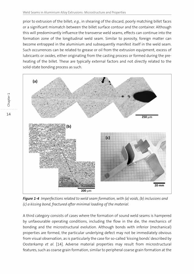
is unfavourable, weld-seam imperfections can occur (Figure 1-4). These phenomena can
lead to sub-standard performance of the material. Porosity can occur on weld seams when
air or gas is entrapped. This can occur when voids are formed in the aluminium bulk just
3 Under certain conditions entrapped oxygen affects bond quality, as discussed in this thesis.
14
Weld Seams in Aluminium Alloy Extrusions: Microstructure and PropertiesC
hap
ter 1
prior to extrusion of the billet; e.g., in shearing of the discard, poorly matching billet faces
or a significant mismatch between the billet surface contour and the container. Although
this will predominantly influence the transverse weld seams, effects can continue into the
formation zone of the longitudinal weld seam. Similar to porosity, foreign matter can
become entrapped in the aluminium and subsequently manifest itself in the weld seam.
Such occurrences can be related to grease or oil from the extrusion equipment, excess of
lubricants or oxides, either originating from the casting process or formed during the pre-
heating of the billet. These are typically external factors and not directly related to the
solid-state bonding process as such.
Figure 1-4 Imperfections related to weld seam formation, with (a) voids, (b) inclusions and
(c) a kissing bond, fractured after minimal loading of the material.
A third category consists of cases where the formation of sound weld seams is hampered
by unfavourable operating conditions, including the flow in the die, the mechanics of
bonding and the microstructural evolution. Although bonds with inferior (mechanical)
properties are formed, the particular underlying defect may not be immediately obvious
from visual observation, as is particularly the case for so-called ‘kissing bonds’ described by
Oosterkamp et al. [14]. Adverse material properties may result from microstructural
features, such as coarse grain formation, similar to peripheral coarse grain formation at the
15
Introduction
Ch
apte
r 1
peripheral areas of an extrusion, partial recrystallisation and grain orientation effects
causing local anisotropy.
1.5 Scope and outline of this thesis
From the above it is clear that charge welds and longitudinal weld seams are important
aspects in structural extrusions. The critical properties of these features are to a large
extent controlled by the characteristics of the bond interfaces. Although a substantial
amount of research has been conducted regarding the topic of extrusion weld seams (as
outlined in the introductory paragraphs of the relevant chapters in this thesis), most work
is to a great extent empirical in nature. Moreover, the bonding process is typically treated
from a mechanical point of view, with disregard for the underlying evolutionary micro-
structural processes. To fully control the weld seam properties, a fundamental understanding
of the solid bonding processes and the resultant development of the microstructures at the
bond interfaces as a function of the alloy composition must be established. The work
described in this thesis focusses on these items.
The outline of this thesis is as follows:
Starting with an introductory chapter, this thesis is further divided into a number of
chapters dealing with specific items connected with weld seam phenomena encountered
in aluminium extrusion.
In Chapter 2 metal flow inside the extrusion tooling is addressed in a more general sense.
The flow particulars give rise to the formation of longitudinal weld seams in extrudates
formed by porthole dies. Moreover, in all extruded parts where billets are consecutively
processed charge welds are formed. Both aspects are related to the metal flow characteristics
which are in turn controlled by the tooling geometry. The influence of die geometry on
material flow is investigated via flow analysis and material characterisation.
Chapter 3 of this thesis focuses specifically on the formation of charge welds. The solid
bonding joining process is considered and properties of charge welds are analysed. Results
are discussed based on the concept of an interface populated by an oxide particle
distribution originating from the contact plane between two successively extruded billets.
In Chapter 4 the microstructure and mechanical properties of aluminium extrusions
containing longitudinal weld seams are investigated. The characteristics of these materials
are compared with the bulk transverse properties obtained under identical processing
conditions. The effects of material flow influencing the microstructure and associated
properties of the longitudinal weld seam are presented.
In Chapter 5 microstructural damage characteristics of longitudinal weld seams are
discussed. In plastic deformation of aluminium the damage evolution is dependent on the
grain structure. In the absence of irregularities as described above the presence of a weld
seam affects the (local) grain structure. Hence the presence of a weld seam can affect the
damage evolution in extruded hollow sections. Through computer tomography studies the
16
Weld Seams in Aluminium Alloy Extrusions: Microstructure and PropertiesC
hap
ter 1
damage distribution is studied and correlated with the specific grain morphology of
extruded samples.
In Chapter 6 longitudinal weld seams are addressed once more, with particular focus on
the occurrence of imperfections resulting from metal flow irregularities. Unfavourable
tooling designs and/or incorrect process settings can lead to conditions resulting in
unsound metal bonding. As a result the formation of a sound weld seam may be impaired.
The thesis ends with a summary of the main findings of the work.
1.6 References
[1] A.J. Den Bakker, W.H. Sillekens, E. Meijers, Aluminium Two Thousand, Interall, Florence,
2007.
[2] M. Lefstad, O. Reiso, S. Johansen, The first EAA extruders division congress, EAA, Bresia, It.,
2002, pp. 2-19.
[3] N.C. Parson, J.D. Hankin, A.J. Bryant, 5th International Aluminum Extrusion Technology
Seminar AEC, Chicago, IL, USA, 1992, pp. 13-23.
[4] R. Ramanan, O. Allen Huff, W. Phillipson, Seventh International Aluminum Extrusion
Technology Seminar, Aluminum Extruders Council, Chicago, IL, USA, 2000, pp. 61-72.
[5] R. Ramanan, J. Fourmann, N. Parson, C. Jowett, Tenth International Aluminum Extrusion
Technology Seminar, ET Foundation, Miami, FL, USA, 2012, pp. 159-200.
[6] J. Hiscocks, L. Jiang, J.J. Jonas, P. Martin, K.P. Boyle, R. Mishra, Canadian Metallurgical
Quarterly, 48 (2009), pp. 161-176.
[7] B. Reggiani, A. Segatori, L. Donati, L. Tomesani, A. Terenzi, A. Salice, in: A.E. Tekkaya, A. Jäger
(Eds.) International Conference on Extrusion and Benchmark ICEB 2013, Trans Tech
Publications, Dortmund, (2014), pp. 111-119.
[8] A.J. Den Bakker, S.P. Edwards, L. ‘t Hoen-Verlterop, R. Ubels, Ninth International Aluminum
Extrusion Technology Seminar, The Aluminum Association, Orlando, FL, USA, 2008.
[9] O. Gjerstad, Untersuchung der Eigenschaften von Langspresnahten an AlMgSi1-
Strangpressprofilen, MSc Thesis, Institut fur Werkstoffkunde, Rheinisch-Westfalische
Technische Hochschule, 1999.
[10] N.E. Nanninga, High Cycle Fatigue of AA6082 and AA6063 Aluminum Extrusions,
Doctoral Thesis, Materials Science and Engineering, Michigan Technological University,
2008.
[11] N.E. Nanninga, C. White, Int. J. Fatigue, 31 (2009), pp. 1215-1224.
[12] M. Engelhardt, D. Behne, N. Grittner, A. Neumann, W. Reimche, C. Klose, in: L. Tomesani,
A.E. Tekkaya (Eds.) Aluminium Two Thousand World Congress and International Conference
on Extrusion and Benchmark ICEB 2015, Materials Today, Florence, Italy, 2015, pp. 4866-
4873.
[13] S.E. Kruger, M. Lord, D. Levesque, A.J. Den Bakker, in: O.T. Donald, E.C. Dale (Eds.) 34th
Annual Review of Progress in Quantitative Nondestructive Evaluation, AIP, Quebec, 2008,
pp. 279-285.
[14] A. Oosterkamp, L.D. Oosterkamp, A. Nordeide, Weld. J., (2004), pp. 255-261.
CHAPTER 2
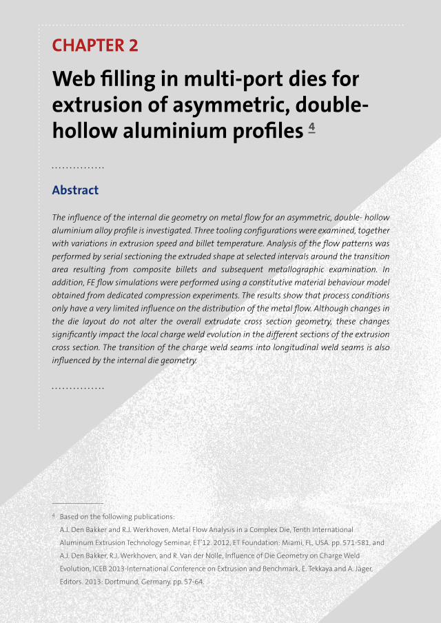
Web filling in multi-port dies for extrusion of asymmetric, double-hollow aluminium profiles 4
Abstract
The influence of the internal die geometry on metal flow for an asymmetric, double- hollow
aluminium alloy profile is investigated. Three tooling configurations were examined, together
with variations in extrusion speed and billet temperature. Analysis of the flow patterns was
performed by serial sectioning the extruded shape at selected intervals around the transition
area resulting from composite billets and subsequent metallographic examination. In
addition, FE flow simulations were performed using a constitutive material behaviour model
obtained from dedicated compression experiments. The results show that process conditions
only have a very limited influence on the distribution of the metal flow. Although changes in
the die layout do not alter the overall extrudate cross section geometry, these changes
significantly impact the local charge weld evolution in the different sections of the extrusion
cross section. The transition of the charge weld seams into longitudinal weld seams is also
influenced by the internal die geometry.
4 Based on the following publications:
A.J. Den Bakker and R.J. Werkhoven, Metal Flow Analysis in a Complex Die, Tenth International
Aluminum Extrusion Technology Seminar, ET’12. 2012, ET Foundation: Miami, FL, USA. pp. 571-581, and
A.J. Den Bakker, R.J. Werkhoven, and R. Van der Nolle, Influence of Die Geometry on Charge Weld
Evolution, ICEB 2013-International Conference on Extrusion and Benchmark, E. Tekkaya and A. Jäger,
Editors. 2013: Dortmund, Germany. pp. 57-64.
18
Weld Seams in Aluminium Alloy Extrusions: Microstructure and PropertiesC
hap
ter 2
2.1 Introduction
Hollow aluminium products with constant cross sectional dimensions are generally
produced through hot extrusion with porthole dies in which a core, also called mandrel, is
internally suspended in the die by means of legs or bridges. The mandrel shape defines the
dimensions of the empty spaces inside the extrusion cross-section. The supports divide the
billet into a number of separate metal streams. In the weld chamber these streams rejoin
to form a continuous shape. At each location where the metal streams are rejoined
longitudinal weld seams are formed. As porthole dies consist of several orifices or ports
feeding the solid aluminium streams into the weld chamber and from there into the
bearing channel, each certain part of the profile is fed by a specific port. In this thesis the
profile sections constrained by the longitudinal weld seams or other types of boundaries
defining a selected part of the extrudate cross-section are termed the webs. Filling of the
webs will depend on the metal volume flow rate through the individual ports. This flow rate
obviously depends on the port size, but is also dependent on the downstream geometrical
features such as the weld chamber volume and the die channel width. Unfavourable flow
characteristics can severely impair the rejoining of the metal streams downstream of the
mandrel supports, causing flow related weld seam defects. The flow dictated by the die
geometry will also impact the transition zone, or charge weld, formed through the joining
of material from the old and new billet. The initially planar contacting billet surfaces are
deformed inside the extrusion tooling, leading to a transition pattern representing the
metal flow distribution in the die. The properties of the bonds formed in the transition
zones, the so-called transverse weld seams, are inferior in comparison with the bulk material
as will be detailed in Chapter 3 of this thesis. In hollow profiles the transverse weld seams
evolve as the cusps of new billet material extend into the transition zones and gradually
merge into the longitudinal weld seams. Consequently the transverse material properties
of the extrudate are initially dominated by the properties of the transverse weld seams,
later to be influenced by the emerging longitudinal weld seams. As the transition of the old
billet material into the new billet material nears completion the mechanical properties are
fully governed by the characteristics of the longitudinal weld seams as will be demonstrated
in Chapter 4 and Chapter 5.
The spatial extent of the charge weld transition, the structure of the longitudinal weld
seams and the resultant properties of the longitudinal weld seams therefore depend to a
great extent on the material flow in the extrusion die. Hence, metal flow in extrusion dies
has been widely investigated. Early work in this field utilised simplified systems with basic
model materials such as plasticine substituting the aluminium alloys [1-3]. Flow patterns
in real aluminium extrusions were analysed by sectioning and etching samples originating
from the container and/or the extruded part. [4-7]. Instead of preparing dedicated billets,
other researchers analysed the deformed grain structure in different areas of the partially
extruded billet and profile and correlated these results with flow characteristics [8]. Many
of these studies utilised simple profile geometries. In solid dies used for extrusion of simple
solid sections such as rods and bars, attention is focussed on the influence of pockets or
19
Web filling in multi-port dies for asymmetric, double-hollow profiles
Ch
apte
r 2
similar types of recesses surrounding the extrusion channel in the die to control profile
characteristics dictated by material flow [9-11]. Cylindrical or square tubes produced by
means of porthole dies are studied with the emphasis on the mechanical process of
material joining in the weld chamber [12-14] and the evolution of the charge welds. These
basic tooling designs do not permit a detailed analysis of the non-uniform material flow
caused by non-uniform or asymmetrical geometrical features such as offset mandrel
supports, varying press channel widths and a decentralised position of the extrudate
relative to the die centre.
With the enhancement of finite element simulation codes, virtual flow analyses can be
performed for arbitrary geometries. This method requires representative descriptions for
material properties, thermal conditions and friction phenomena. For this, comparison with
physical flow experiments is crucial and the outcome of these experiments can be used to
validate simulation results [15-19]. In an early study by Bourqui et al. the weld seam quality
of a multi-hollow, asymmetrical extrusion was improved through modification of the die
design [20]. Their study was based on calculated local pressure and temperature in the
weld chamber without considering material flow effects. In a later modelling study by
Ceretti the influence of the shape of the mandrel supports and the resultant porthole
dimensions were investigated [21]. Thin mandrel supports facilitated metal flow due to the
larger resultant ports, whilst dissimilar port sizes cause unbalanced material streams. The
authors postulated that such a behaviour would lead to inferior longitudinal weld seams
due to an inhomogeneous material structure [22]. The modelling results were however not
validated via physical experiments. In a recent study by Mahmoodkhani material flow
related to transverse weld formation in billet-to-billet extrusion of a round bar was studied
[23]. Modelling results were compared with experiments, focussing on the shape of the
billet transition resulting from dies with different feeder shapes. In that study it was found
that a tapered geometry of the feeder ports reduces the dead metal zone volumes in the
die, thereby effectively reducing the billet transition length.
The studies discussed above are limited in the sense that they are largely constrained to
basic, symmetrical shapes. In studies focussing on more complex geometries, the flow
particulars are studied solely through modelling with indirect conclusions concerning weld
seam properties, or a singular aspect concerning weld seam quality is addressed,
disregarding metal flow phenomena though the entire extrusion cross section.
In the present study the influence of the die geometry on the charge weld transition and
evolution of the charge welds into longitudinal weld seams under steady state conditions
is investigated for a complex, asymmetric double hollow extrusion. Keeping the nominal
shape of the extrudate geometry unchanged, several die geometries are studied. Flow
particulars are analysed through FE-simulations and validated by means of extrusion trials.
For this purpose a constitutive material model was implemented in the FE-model utilising
data derived from dedicated uniaxial compression tests.
20
Weld Seams in Aluminium Alloy Extrusions: Microstructure and PropertiesC
hap
ter 2
2.2 Flow simulation
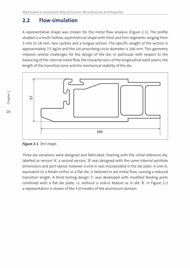
A representative shape was chosen for the metal flow analysis (Figure 2-1). The profile
studied is a multi-hollow, asymmetrical shape with thick and thin segments ranging from
3 mm to 18 mm, two cavities and a tongue section. The specific weight of the section is
approximately 7.5 kg/m and the circumscribing circle diameter is 166 mm. This geometry
imposes several challenges for the design of the die, in particular with respect to the
balancing of the internal metal flow, the characteristics of the longitudinal weld seams, the
length of the transition zone and the mechanical stability of the die.
Figure 2-1 Test shape.
Three die variations were designed and fabricated. Starting with the initial reference die,
labelled as version ‘A‘, a second version, ’B‘ was designed with the same internal porthole
dimensions and port layout, however a sink-in was incorporated in the die plate. A sink-in,
equivalent to a feeder orifice in a flat die, is believed to aid metal flow, causing a reduced
transition length. A third tooling design ‘C’ was developed with modified feeding ports
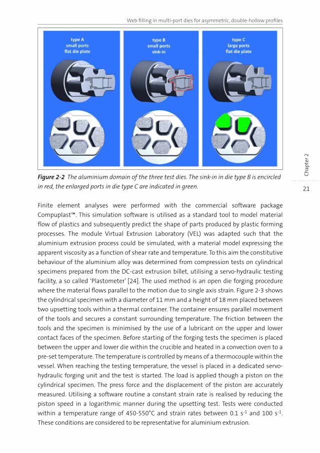
combined with a flat die plate, i.e. without a sink-in feature as in die ’B’. In Figure 2-2
a representation is shown of the 3-D models of the aluminium domain.
21
Web filling in multi-port dies for asymmetric, double-hollow profiles
Ch
apte
r 2
Figure 2-2 The aluminium domain of the three test dies. The sink-in in die type B is encircled
in red, the enlarged ports in die type C are indicated in green.
Finite element analyses were performed with the commercial software package
Compuplast™. This simulation software is utilised as a standard tool to model material
flow of plastics and subsequently predict the shape of parts produced by plastic forming
processes. The module Virtual Extrusion Laboratory (VEL) was adapted such that the
aluminium extrusion process could be simulated, with a material model expressing the
apparent viscosity as a function of shear rate and temperature. To this aim the constitutive
behaviour of the aluminium alloy was determined from compression tests on cylindrical
specimens prepared from the DC-cast extrusion billet, utilising a servo-hydraulic testing
facility, a so called ‘Plastometer’ [24]. The used method is an open die forging procedure
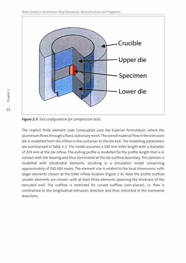
where the material flows parallel to the motion due to single axis strain. Figure 2-3 shows
the cylindrical specimen with a diameter of 11 mm and a height of 18 mm placed between
two upsetting tools within a thermal container. The container ensures parallel movement
of the tools and secures a constant surrounding temperature. The friction between the
tools and the specimen is minimised by the use of a lubricant on the upper and lower
contact faces of the specimen. Before starting of the forging tests the specimen is placed
between the upper and lower die within the crucible and heated in a convection oven to a
pre-set temperature. The temperature is controlled by means of a thermocouple within the
vessel. When reaching the testing temperature, the vessel is placed in a dedicated servo-
hydraulic forging unit and the test is started. The load is applied though a piston on the
cylindrical specimen. The press force and the displacement of the piston are accurately
measured. Utilising a software routine a constant strain rate is realised by reducing the
piston speed in a logarithmic manner during the upsetting test. Tests were conducted
within a temperature range of 450-550°C and strain rates between 0.1 s-1 and 100 s-1.
These conditions are considered to be representative for aluminium extrusion.
22
Weld Seams in Aluminium Alloy Extrusions: Microstructure and PropertiesC
hap
ter 2
Figure 2-3 Tool configuration for compression tests.
The implicit finite element code Compuplast uses the Eulerian formulation, where the
aluminium flows through a fixed, stationary mesh. The overall material flow in the extrusion
die is modelled from the inflow in the container to the die exit. The modelling parameters
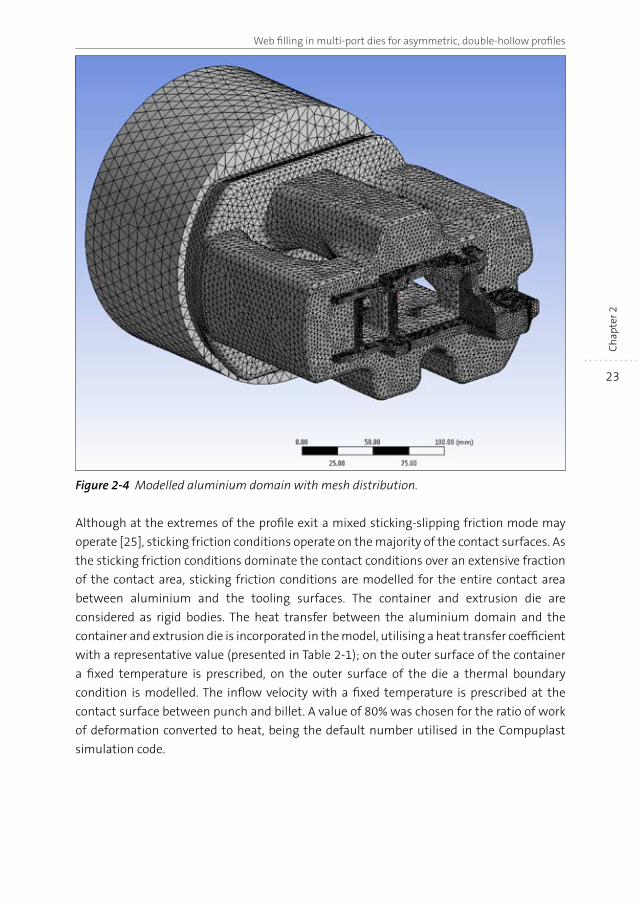
are summarised in Table 2-1. The model assumes a 100 mm billet length with a diameter
of 203 mm at the die inflow. The exiting profile is modelled for the profile length that is in
contact with the bearing and thus terminated at the die outflow boundary. This domain is
modelled with tetrahedral elements, resulting in a simulation model comprising
approximately of 500 000 nodes. The element size is related to the local dimensions, with
larger elements chosen at the billet inflow location (Figure 2-4). Near the profile outflow
smaller elements are chosen, with at least three elements spanning the thickness of the
extruded wall. The outflow is restricted for curved outflow (non-planar), i.e. flow is
constrained to the longitudinal extrusion direction and thus restricted in the transverse
directions.
23
Web filling in multi-port dies for asymmetric, double-hollow profiles
Ch
apte
r 2
Figure 2-4 Modelled aluminium domain with mesh distribution.
Although at the extremes of the profile exit a mixed sticking-slipping friction mode may
operate [25], sticking friction conditions operate on the majority of the contact surfaces. As
the sticking friction conditions dominate the contact conditions over an extensive fraction
of the contact area, sticking friction conditions are modelled for the entire contact area
between aluminium and the tooling surfaces. The container and extrusion die are
considered as rigid bodies. The heat transfer between the aluminium domain and the
container and extrusion die is incorporated in the model, utilising a heat transfer coefficient
with a representative value (presented in Table 2-1); on the outer surface of the container
a fixed temperature is prescribed, on the outer surface of the die a thermal boundary
condition is modelled. The inflow velocity with a fixed temperature is prescribed at the
contact surface between punch and billet. A value of 80% was chosen for the ratio of work
of deformation converted to heat, being the default number utilised in the Compuplast
simulation code.
24
Weld Seams in Aluminium Alloy Extrusions: Microstructure and PropertiesC
hap
ter 2
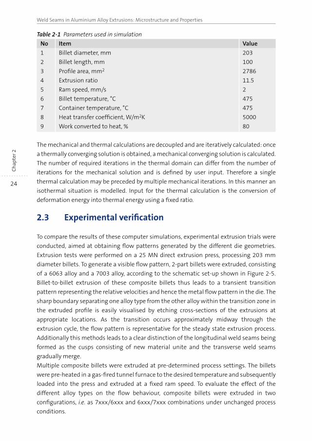
Table 2-1 Parameters used in simulation
No Item Value
1 Billet diameter, mm 203
2 Billet length, mm 100
3 Profile area, mm2 2786
4 Extrusion ratio 11.5
5 Ram speed, mm/s 2
6 Billet temperature, °C 475
7 Container temperature, °C 475
8 Heat transfer coefficient, W/m2K 5000
9 Work converted to heat, % 80
The mechanical and thermal calculations are decoupled and are iteratively calculated: once
a thermally converging solution is obtained, a mechanical converging solution is calculated.
The number of required iterations in the thermal domain can differ from the number of
iterations for the mechanical solution and is defined by user input. Therefore a single
thermal calculation may be preceded by multiple mechanical iterations. In this manner an
isothermal situation is modelled. Input for the thermal calculation is the conversion of
deformation energy into thermal energy using a fixed ratio.
2.3 Experimental verification
To compare the results of these computer simulations, experimental extrusion trials were
conducted, aimed at obtaining flow patterns generated by the different die geometries.
Extrusion tests were performed on a 25 MN direct extrusion press, processing 203 mm
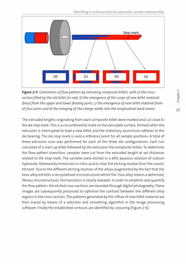
diameter billets. To generate a visible flow pattern, 2-part billets were extruded, consisting
of a 6063 alloy and a 7003 alloy, according to the schematic set-up shown in Figure 2-5.
Billet-to-billet extrusion of these composite billets thus leads to a transient transition
pattern representing the relative velocities and hence the metal flow pattern in the die. The
sharp boundary separating one alloy type from the other alloy within the transition zone in
the extruded profile is easily visualised by etching cross-sections of the extrusions at
appropriate locations. As the transition occurs approximately midway through the
extrusion cycle, the flow pattern is representative for the steady state extrusion process.
Additionally this methods leads to a clear distinction of the longitudinal weld seams being
formed as the cusps consisting of new material unite and the transverse weld seams
gradually merge.
Multiple composite billets were extruded at pre-determined process settings. The billets
were pre-heated in a gas-fired tunnel furnace to the desired temperature and subsequently
loaded into the press and extruded at a fixed ram speed. To evaluate the effect of the
different alloy types on the flow behaviour, composite billets were extruded in two
configurations, i.e. as 7xxx/6xxx and 6xxx/7xxx combinations under unchanged process
conditions.
25
Web filling in multi-port dies for asymmetric, double-hollow profiles
Ch
apte
r 2Figure 2-5 Generation of flow pattern by extruding composite billets, with a) the cross-
section filled by the old billet (in red), b) the emergence of the cusps of new billet material
(blue) from the upper and lower feeding ports, c) the emergence of new billet material from
all four ports and d) the merging of the charge welds into the longitudinal weld seams.
The extruded lengths originating from each composite billet were marked and cut close to
the die stop mark. This is a circumferential mark on the extrudate surface, formed when the
extrusion is interrupted to load a new billet and the stationary aluminium adheres to the
die bearing. The die stop mark is used a reference point for all sample positions. A total of
three extrusion runs was performed for each of the three die configurations. Each run
consisted of a start-up billet followed by the extrusion the composite billets. To determine
the flow pattern transition, samples were cut from the extruded length at set distances
related to the stop mark. The samples were etched in a 60% aqueous solution of sodium
hydroxide, followed by immersion in nitric acid to clear the etching residue from the caustic
etchant. Due to the different etching reaction of the alloys (augmented by the fact that the
6xxx alloy exhibits a recrystallised microstructure whilst the 7xxx alloy retains a deformed,
fibrous microstructure), the transition is clearly revealed. In order to establish and quantify
the flow pattern, the etched cross sections are recorded through digital photography. These
images are subsequently processed to optimise the contrast between the different alloy
regions in the cross-section. The patterns generated by the inflow of new billet material are
then traced by means of a selection and smoothing algorithm in the image processing
software. Finally the established contours are identified by colouring (Figure 2-6).
26
Weld Seams in Aluminium Alloy Extrusions: Microstructure and PropertiesC
hap
ter 2
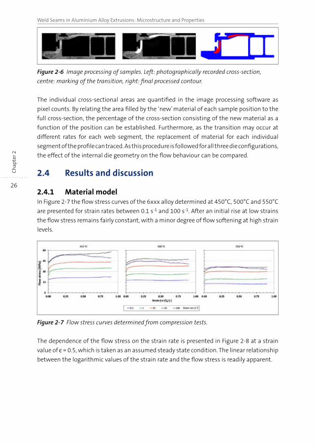
Figure 2-6 Image processing of samples. Left: photographically recorded cross-section,
centre: marking of the transition, right: final processed contour.
The individual cross-sectional areas are quantified in the image processing software as
pixel counts. By relating the area filled by the ‘new’ material of each sample position to the
full cross-section, the percentage of the cross-section consisting of the new material as a
function of the position can be established. Furthermore, as the transition may occur at
different rates for each web segment, the replacement of material for each individual
segment of the profile can traced. As this procedure is followed for all three die configurations,
the effect of the internal die geometry on the flow behaviour can be compared.
2.4 Results and discussion
2.4.1 Material modelIn Figure 2-7 the flow stress curves of the 6xxx alloy determined at 450°C, 500°C and 550°C
are presented for strain rates between 0.1 s-1 and 100 s-1. After an initial rise at low strains
the flow stress remains fairly constant, with a minor degree of flow softening at high strain
levels.
Figure 2-7 Flow stress curves determined from compression tests.
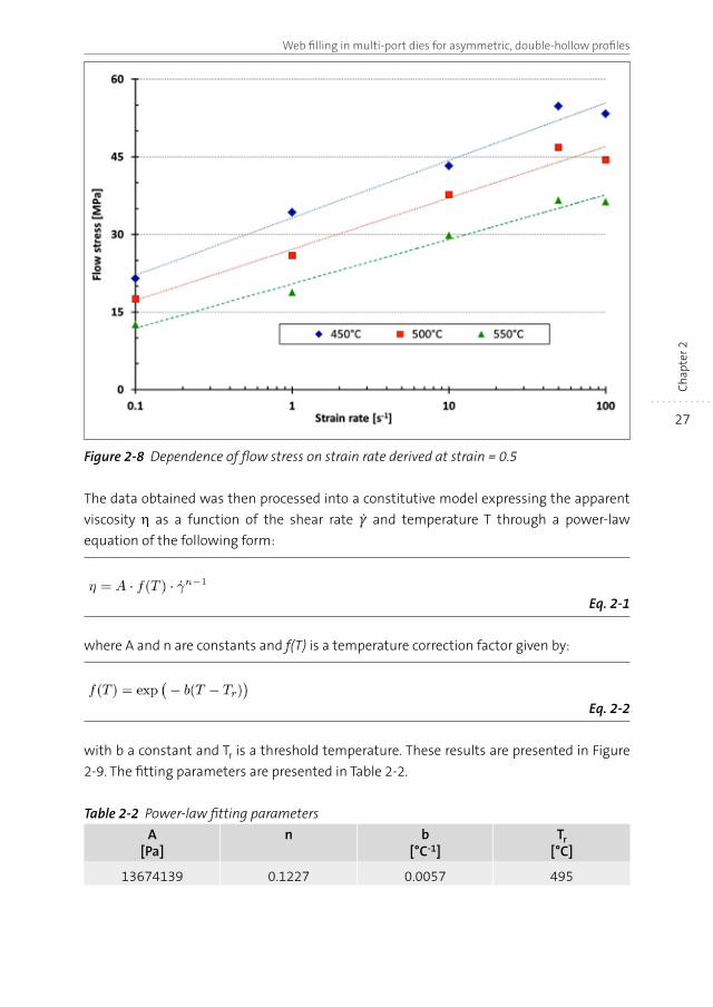
The dependence of the flow stress on the strain rate is presented in Figure 2-8 at a strain
value of ε = 0.5, which is taken as an assumed steady state condition. The linear relationship
between the logarithmic values of the strain rate and the flow stress is readily apparent.
27
Web filling in multi-port dies for asymmetric, double-hollow profiles
Ch
apte
r 2
Figure 2-8 Dependence of flow stress on strain rate derived at strain = 0.5
The data obtained was then processed into a constitutive model expressing the apparent
viscosity η as a function of the shear rate and temperature T through a power-law
equation of the following form:
Eq. 2-1
where A and n are constants and f(T) is a temperature correction factor given by:
Eq. 2-2
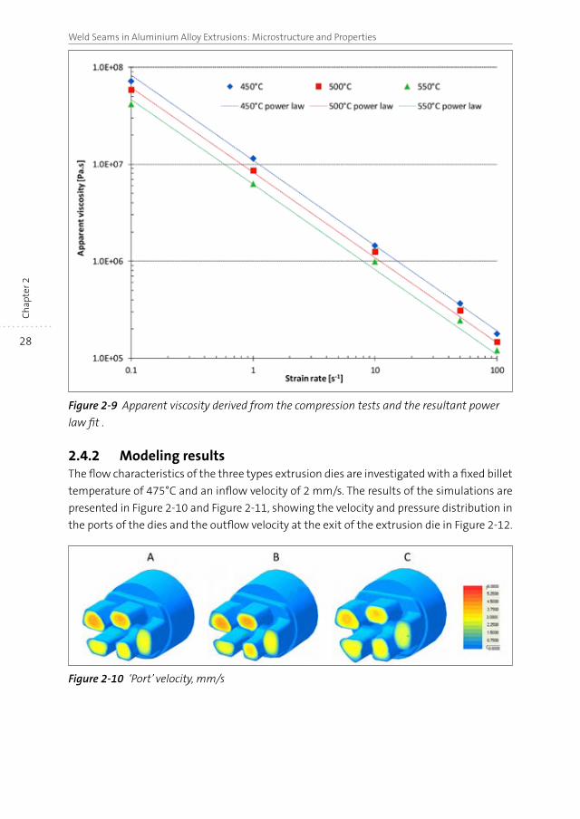
with b a constant and Tr is a threshold temperature. These results are presented in Figure
2-9. The fitting parameters are presented in Table 2-2.
Table 2-2 Power-law fitting parameters
A[Pa]
n b[°C-1]
Tr[°C]
13674139 0.1227 0.0057 495
28
Weld Seams in Aluminium Alloy Extrusions: Microstructure and PropertiesC
hap
ter 2
Figure 2-9 Apparent viscosity derived from the compression tests and the resultant power
law fit .
2.4.2 Modeling resultsThe flow characteristics of the three types extrusion dies are investigated with a fixed billet
temperature of 475°C and an inflow velocity of 2 mm/s. The results of the simulations are
presented in Figure 2-10 and Figure 2-11, showing the velocity and pressure distribution in
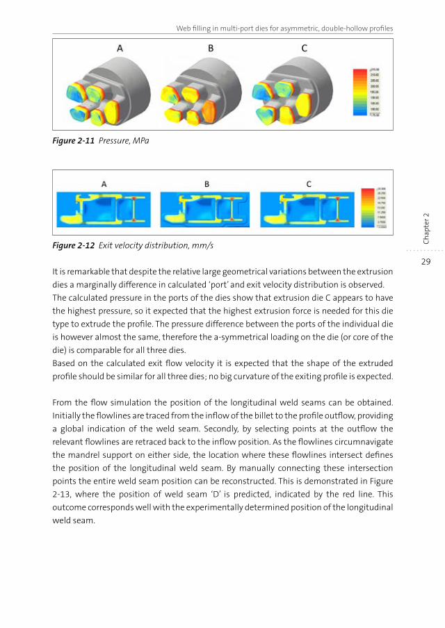
the ports of the dies and the outflow velocity at the exit of the extrusion die in Figure 2-12.
Figure 2-10 ‘Port’ velocity, mm/s
29
Web filling in multi-port dies for asymmetric, double-hollow profiles
Ch
apte
r 2
Figure 2-11 Pressure, MPa
Figure 2-12 Exit velocity distribution, mm/s
It is remarkable that despite the relative large geometrical variations between the extrusion
dies a marginally difference in calculated ‘port’ and exit velocity distribution is observed.
The calculated pressure in the ports of the dies show that extrusion die C appears to have
the highest pressure, so it expected that the highest extrusion force is needed for this die
type to extrude the profile. The pressure difference between the ports of the individual die
is however almost the same, therefore the a-symmetrical loading on the die (or core of the
die) is comparable for all three dies.
Based on the calculated exit flow velocity it is expected that the shape of the extruded
profile should be similar for all three dies; no big curvature of the exiting profile is expected.
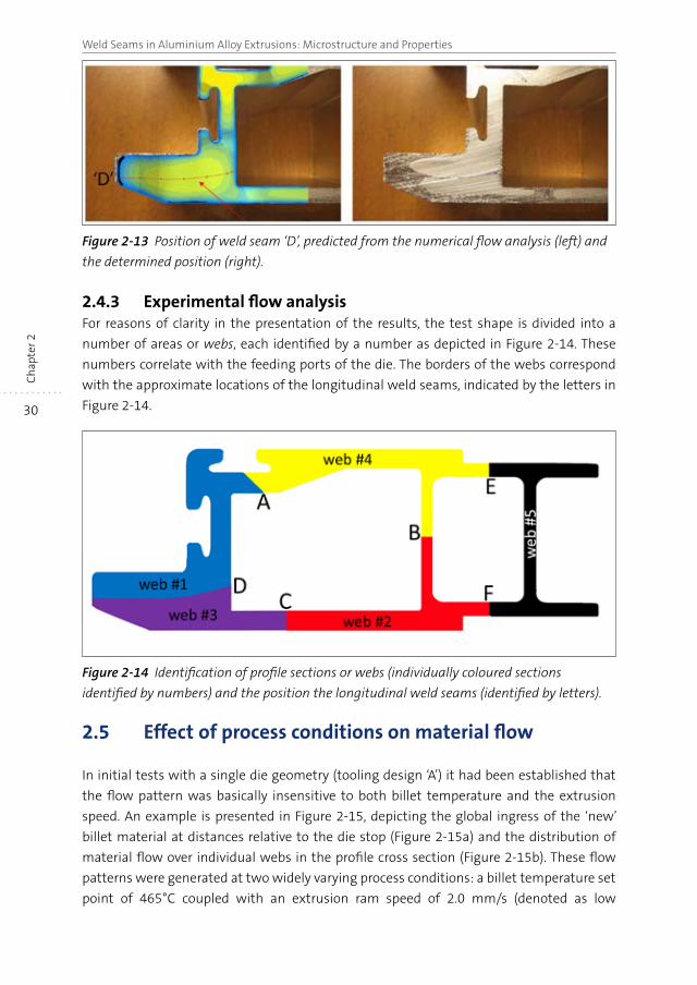
From the flow simulation the position of the longitudinal weld seams can be obtained.
Initially the flowlines are traced from the inflow of the billet to the profile outflow, providing
a global indication of the weld seam. Secondly, by selecting points at the outflow the
relevant flowlines are retraced back to the inflow position. As the flowlines circumnavigate
the mandrel support on either side, the location where these flowlines intersect defines
the position of the longitudinal weld seam. By manually connecting these intersection
points the entire weld seam position can be reconstructed. This is demonstrated in Figure
2-13, where the position of weld seam ‘D’ is predicted, indicated by the red line. This
outcome corresponds well with the experimentally determined position of the longitudinal
weld seam.
30
Weld Seams in Aluminium Alloy Extrusions: Microstructure and PropertiesC
hap
ter 2
Figure 2-13 Position of weld seam ‘D’, predicted from the numerical flow analysis (left) and
the determined position (right).
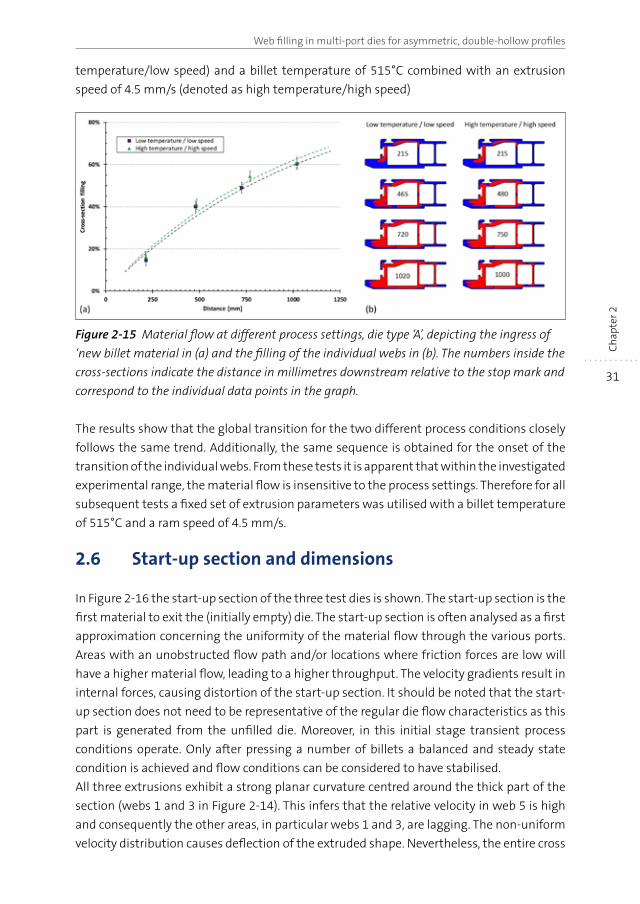
2.4.3 Experimental flow analysisFor reasons of clarity in the presentation of the results, the test shape is divided into a
number of areas or webs, each identified by a number as depicted in Figure 2-14. These
numbers correlate with the feeding ports of the die. The borders of the webs correspond
with the approximate locations of the longitudinal weld seams, indicated by the letters in
Figure 2-14.
Figure 2-14 Identification of profile sections or webs (individually coloured sections
identified by numbers) and the position the longitudinal weld seams (identified by letters).
2.5 Effect of process conditions on material flow
In initial tests with a single die geometry (tooling design ‘A’) it had been established that
the flow pattern was basically insensitive to both billet temperature and the extrusion
speed. An example is presented in Figure 2-15, depicting the global ingress of the ‘new’
billet material at distances relative to the die stop (Figure 2-15a) and the distribution of
material flow over individual webs in the profile cross section (Figure 2-15b). These flow
patterns were generated at two widely varying process conditions: a billet temperature set
point of 465°C coupled with an extrusion ram speed of 2.0 mm/s (denoted as low
31
Web filling in multi-port dies for asymmetric, double-hollow profiles
Ch
apte
r 2
temperature/low speed) and a billet temperature of 515°C combined with an extrusion
speed of 4.5 mm/s (denoted as high temperature/high speed)
Figure 2-15 Material flow at different process settings, die type ‘A’, depicting the ingress of
‘new billet material in (a) and the filling of the individual webs in (b). The numbers inside the
cross-sections indicate the distance in millimetres downstream relative to the stop mark and
correspond to the individual data points in the graph.
The results show that the global transition for the two different process conditions closely
follows the same trend. Additionally, the same sequence is obtained for the onset of the
transition of the individual webs. From these tests it is apparent that within the investigated
experimental range, the material flow is insensitive to the process settings. Therefore for all
subsequent tests a fixed set of extrusion parameters was utilised with a billet temperature
of 515°C and a ram speed of 4.5 mm/s.
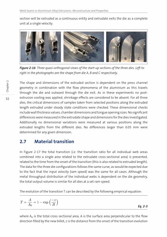
2.6 Start-up section and dimensions
In Figure 2-16 the start-up section of the three test dies is shown. The start-up section is the
first material to exit the (initially empty) die. The start-up section is often analysed as a first
approximation concerning the uniformity of the material flow through the various ports.
Areas with an unobstructed flow path and/or locations where friction forces are low will
have a higher material flow, leading to a higher throughput. The velocity gradients result in
internal forces, causing distortion of the start-up section. It should be noted that the start-
up section does not need to be representative of the regular die flow characteristics as this
part is generated from the unfilled die. Moreover, in this initial stage transient process
conditions operate. Only after pressing a number of billets a balanced and steady state
condition is achieved and flow conditions can be considered to have stabilised.
All three extrusions exhibit a strong planar curvature centred around the thick part of the
section (webs 1 and 3 in Figure 2-14). This infers that the relative velocity in web 5 is high
and consequently the other areas, in particular webs 1 and 3, are lagging. The non-uniform
velocity distribution causes deflection of the extruded shape. Nevertheless, the entire cross
32
Weld Seams in Aluminium Alloy Extrusions: Microstructure and PropertiesC
hap
ter 2
section will be extruded as a continuous entity and extrudate exits the die as a complete
unit at a single velocity.
Figure 2-16 Three quasi-orthogonal views of the start-up sections of the three dies. Left to
right in the photographs are the shape from die A, B and C respectively.
The shape and dimensions of the extruded section is dependent on the press channel
geometry in combination with the flow phenomena of the aluminium as this travels
through the die and outward through the die exit. As in these experiments no post-
extrusion cooling was applied, shrinkage effects are considered to be absent. For all three
dies, the critical dimensions of samples taken from selected positions along the extruded
length extruded under steady state conditions were checked. These dimensional checks
include wall thickness values, chamber dimensions and tongue opening sizes. No significant
differences were measured in the extrudate shape and dimensions for the dies investigated.
Additionally no dimensional variations were measured at various positions along the
extruded lengths from the different dies. No differences larger than 0.05 mm were
determined for any given dimension.
2.7 Material transition
In Figure 2-17 the total transition (i.e. the transition ratio for all individual web areas
combined into a single area related to the extrudate cross-sectional area) is presented,
related to the time from the onset of the transition (this is also related to extruded length).
The data for the three die configurations follows the same curve, as would be expected due
to the fact that the input velocity (ram speed) was the same for all cases. Although the
metal throughput distribution of the individual webs is dependent on the die geometry,
the total output volume is similar for all dies at a set ram speed.
The evolution of the transition T can be described by the following empirical equation:
Eq. 2-3
where A0 is the total cross sectional area, A is the surface area perpendicular to the flow
direction filled by the new billet, z is the distance from the onset of the transition evolution
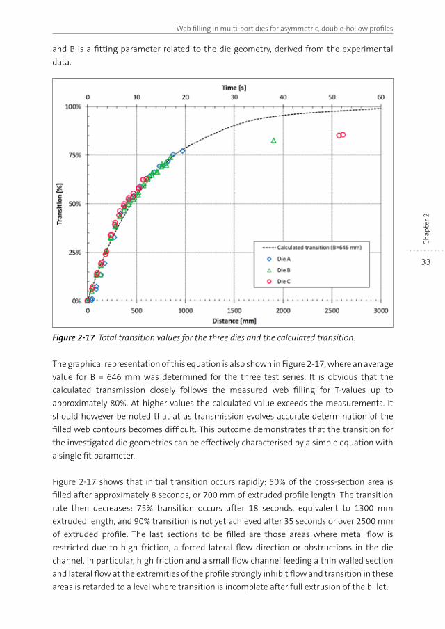
33
Web filling in multi-port dies for asymmetric, double-hollow profiles
Ch
apte
r 2
and B is a fitting parameter related to the die geometry, derived from the experimental
data.
Figure 2-17 Total transition values for the three dies and the calculated transition.
The graphical representation of this equation is also shown in Figure 2-17, where an average
value for B = 646 mm was determined for the three test series. It is obvious that the
calculated transmission closely follows the measured web filling for T-values up to
approximately 80%. At higher values the calculated value exceeds the measurements. It
should however be noted that at as transmission evolves accurate determination of the
filled web contours becomes difficult. This outcome demonstrates that the transition for
the investigated die geometries can be effectively characterised by a simple equation with
a single fit parameter.
Figure 2-17 shows that initial transition occurs rapidly: 50% of the cross-section area is
filled after approximately 8 seconds, or 700 mm of extruded profile length. The transition
rate then decreases: 75% transition occurs after 18 seconds, equivalent to 1300 mm
extruded length, and 90% transition is not yet achieved after 35 seconds or over 2500 mm
of extruded profile. The last sections to be filled are those areas where metal flow is
restricted due to high friction, a forced lateral flow direction or obstructions in the die
channel. In particular, high friction and a small flow channel feeding a thin walled section
and lateral flow at the extremities of the profile strongly inhibit flow and transition in these
areas is retarded to a level where transition is incomplete after full extrusion of the billet.
34
Weld Seams in Aluminium Alloy Extrusions: Microstructure and PropertiesC
hap
ter 2
2.8 Local material flow
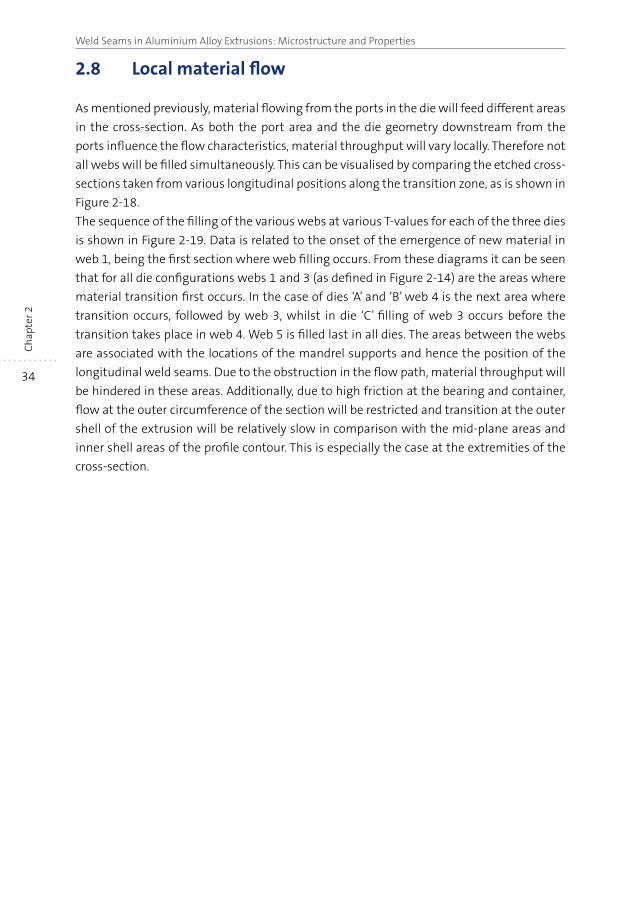
As mentioned previously, material flowing from the ports in the die will feed different areas
in the cross-section. As both the port area and the die geometry downstream from the
ports influence the flow characteristics, material throughput will vary locally. Therefore not
all webs will be filled simultaneously. This can be visualised by comparing the etched cross-
sections taken from various longitudinal positions along the transition zone, as is shown in
Figure 2-18.
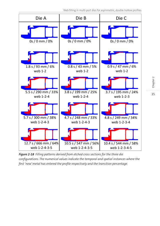
The sequence of the filling of the various webs at various T-values for each of the three dies
is shown in Figure 2-19. Data is related to the onset of the emergence of new material in
web 1, being the first section where web filling occurs. From these diagrams it can be seen
that for all die configurations webs 1 and 3 (as defined in Figure 2-14) are the areas where
material transition first occurs. In the case of dies ‘A’ and ‘B’ web 4 is the next area where
transition occurs, followed by web 3, whilst in die ‘C’ filling of web 3 occurs before the
transition takes place in web 4. Web 5 is filled last in all dies. The areas between the webs
are associated with the locations of the mandrel supports and hence the position of the
longitudinal weld seams. Due to the obstruction in the flow path, material throughput will
be hindered in these areas. Additionally, due to high friction at the bearing and container,
flow at the outer circumference of the section will be restricted and transition at the outer
shell of the extrusion will be relatively slow in comparison with the mid-plane areas and
inner shell areas of the profile contour. This is especially the case at the extremities of the
cross-section.
35
Web filling in multi-port dies for asymmetric, double-hollow profiles
Ch
apte
r 2Figure 2-18 Filling patterns derived from etched cross sections for the three die
configurations. The numerical values indicate the temporal and spatial instances where the
first ‘new’ metal has entered the profile respectively and the transition percentage.
36
Weld Seams in Aluminium Alloy Extrusions: Microstructure and PropertiesC
hap
ter 2
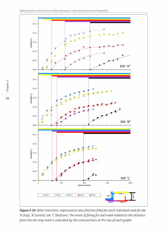
Figure 2-19 Billet transition, expressed as area fraction filled for each individual web for die
‘A’ (top), ‘B’ (centre), die ‘C’ (bottom). The onset of filling for each web related to the distance
from the die-stop mark is indicated by the coloured bars at the top of each graph.
37
Web filling in multi-port dies for asymmetric, double-hollow profiles
Ch
apte
r 2
With reference to the die geometries (Figure 2-2), it is clear that the pocket in the die plate
of die type B has only a minor effect on the metal flow distribution in the die. The order in
which the onset of web filling occurs is the same for both die type ‘A’ and type ‘B’. By
changing the port dimensions in die ‘C’, in particular increasing the dimensions of the ports
feeding web 3, the filling rate for this web is increased. As a result the onset of web filling
of web 3 now occurs prior to that of web 4, in contrast to the sequence observed in dies ‘A’
and ‘B’. The change in port dimensions also has a minor effect on the feeding of web 5 in
the sense that the start of web filling occurs slightly earlier in comparison with die types ‘A’
and ‘B’.
In Figure 2-19 the transition values for each web, expressed as the area fraction related to
the total cross section, are presented for the three dies, based on measurements from
samples taken at approximately 50 mm intervals. The individual web filling or transition
can only partially be traced, as patterns merge across the location of the longitudinal weld
seam and individual webs unite to form a singular area. In line with the observations
presented above, transition occurs first in webs 1 and 2. After approximately 2.7 seconds
transition starts in web 4 for dies ‘A’ and ‘B’, contrary to die ‘C’ where the next transition
starts in web 3 after approximately 3 seconds and is then rapidly followed by web 4. For
dies ‘A’ and ‘B’ the transition in web 4 starts after respectively 5.5 seconds and 3.8 seconds.
In all dies web 5 is the last section where transition occurs, after approximately 10 seconds.
Once started, web filling starts rapidly then gradually levels off to a more gradual rate.
Webs 1 and 2 fill approximately 35% of the cross-section after 10 seconds, with webs 3 and
4 then accounting for 20%. Only after approximately 10 second web 5 contributes to the
transition. As mentioned above the effect of the enlarged ports feeding webs 1 and 3 in die
‘C’ indeed brings the start of transition of web 3 forward (as compared to die ‘A’), at the
costs of delaying the onset of transition in web 4. Only marginal differences are observed
for web 5.
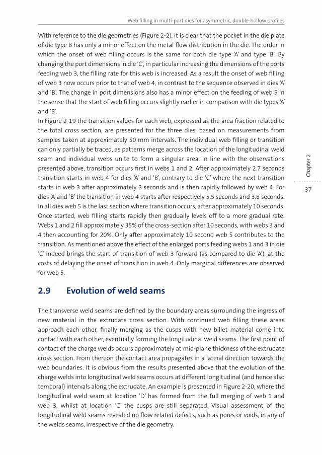
2.9 Evolution of weld seams
The transverse weld seams are defined by the boundary areas surrounding the ingress of
new material in the extrudate cross section. With continued web filling these areas
approach each other, finally merging as the cusps with new billet material come into
contact with each other, eventually forming the longitudinal weld seams. The first point of
contact of the charge welds occurs approximately at mid-plane thickness of the extrudate
cross section. From thereon the contact area propagates in a lateral direction towards the
web boundaries. It is obvious from the results presented above that the evolution of the
charge welds into longitudinal weld seams occurs at different longitudinal (and hence also
temporal) intervals along the extrudate. An example is presented in Figure 2-20, where the
longitudinal weld seam at location ’D’ has formed from the full merging of web 1 and
web 3, whilst at location ‘C’ the cusps are still separated. Visual assessment of the
longitudinal weld seams revealed no flow related defects, such as pores or voids, in any of
the welds seams, irrespective of the die geometry.
38
Weld Seams in Aluminium Alloy Extrusions: Microstructure and PropertiesC
hap
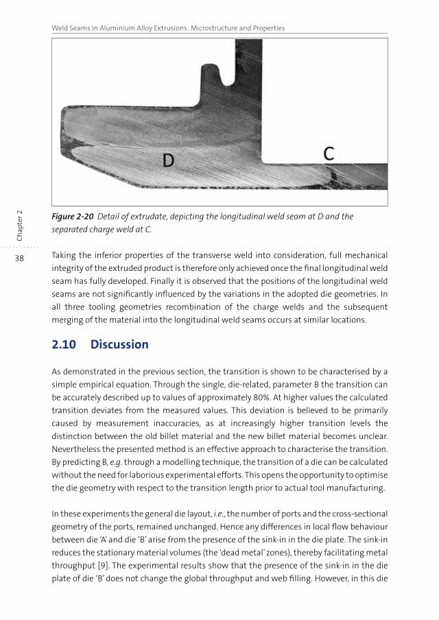
ter 2 Figure 2-20 Detail of extrudate, depicting the longitudinal weld seam at D and the
separated charge weld at C.
Taking the inferior properties of the transverse weld into consideration, full mechanical
integrity of the extruded product is therefore only achieved once the final longitudinal weld
seam has fully developed. Finally it is observed that the positions of the longitudinal weld
seams are not significantly influenced by the variations in the adopted die geometries. In
all three tooling geometries recombination of the charge welds and the subsequent
merging of the material into the longitudinal weld seams occurs at similar locations.
2.10 Discussion
As demonstrated in the previous section, the transition is shown to be characterised by a
simple empirical equation. Through the single, die-related, parameter B the transition can
be accurately described up to values of approximately 80%. At higher values the calculated
transition deviates from the measured values. This deviation is believed to be primarily
caused by measurement inaccuracies, as at increasingly higher transition levels the
distinction between the old billet material and the new billet material becomes unclear.
Nevertheless the presented method is an effective approach to characterise the transition.
By predicting B, e.g. through a modelling technique, the transition of a die can be calculated
without the need for laborious experimental efforts. This opens the opportunity to optimise
the die geometry with respect to the transition length prior to actual tool manufacturing.
In these experiments the general die layout, i.e., the number of ports and the cross-sectional
geometry of the ports, remained unchanged. Hence any differences in local flow behaviour
between die ‘A’ and die ‘B’ arise from the presence of the sink-in in the die plate. The sink-in
reduces the stationary material volumes (the ‘dead metal’ zones), thereby facilitating metal
throughput [9]. The experimental results show that the presence of the sink-in in the die
plate of die ‘B’ does not change the global throughput and web filling. However, in this die
39
Web filling in multi-port dies for asymmetric, double-hollow profiles
Ch
apte
r 2
enhanced flow has occurred through the port feeding web 3, resulting in an earlier onset of
web filling. Conversely, the feeding rate of web 1 and web 4 is somewhat reduced.
Similarly, increasing the size of the ports feeding web 3 in die ‘C’ in comparison with the
standard port size in die ‘A’ significantly shortens the delay prior to the onset filling of web 3.
This change is associated with a minor increase in the onset of web filling of web 4. The
change in port dimensions also causes a minor reduction in the delay of web filling for
web 5. Globally it may therefore be stated that the change in port size causes a somewhat
more balanced flow with a reduced spread in the start of web filling of the individual webs.
It remains however readily apparent that feeding of the relatively small area of web 5
remains lagging, despite the large feeder port. Although the addition of a sink-in in the die
feeder plate also is shown to balance material throughput, the change in port dimensions
proves to be a more effective method to equalise material flow. The limited changes in
geometries are also reflected in the unchanged positions of the longitudinal weld seams.
Comparing simulation results with the outcome of the extrusion trials, there appears to be
a disparity between the simulated velocities in different areas of the profile cross-section
and the corresponding flow patterns as determined from the etched cross-sections.
Whereas the FEM simulation results indicate the highest velocity occurring in web 5 (as
defined in Figure 2-14), the flow analysis performed on the etched cross-sections indicate
that these parts emerge last, i.e. this material having the lowest velocity, whilst the highest
throughput is obtained in web 1 and web 2.
However, in contrast to these observations, velocities obtained from the simulations
compare well with the apparent velocities as derived from the start-up sections shown in
Figure 2-16. The curvature of these parts suggest the highest velocity for the material
emerging from web 5, which is in line with the simulated velocity profiles presented in
Figure 2-12. Therefore it may be reasoned that simulation represents the situation of the
unfilled die. As is apparent from the model set-up, this is not actually the case: simulation
is based on a pre-filled die with the objective of predicting flow during the steady-state
process.
These observations can be explained by the fact that in the applied simulation model
history effects, i.e. forces and deformations acting on the material as this travels through
the die, are based on the same fixed time-step for all particles at their respective position
inside the die. Thus, the simulation model depicts an ‘instantaneous’ situation, which for
this situation is fixed in time (for each particular time step which is analysed). Obviously,
this differs from the experimental case: each individual material unit or particle flowing
from the billet through the die into the profile cross-section will undergo a particular
deformation path, influenced by the specific – transient – conditions for that material
particle. Hence a planar surface inside the billet entering the die will emerge as a deformed
surface corresponding with the flow patterns depicted in Figure 2-18. In contrast, the
simulation can be regarded as assuming a planar surface at the die exit as a starting point
for flow calculations, disregarding the forces and deformations previously exerted on the
material as this has transgressed the container and die, in reality causing a non-planar
40
Weld Seams in Aluminium Alloy Extrusions: Microstructure and PropertiesC
hap
ter 2
cross section surface at each point from the billet to the profile exit. The modelling outcome
demonstrates the capability to predict the correct location of the longitudinal weld seams.
The adopted method relies however on a manual post-processing operation by tracing the
flow lines, thereby obtaining the point of intersection downstream of the mandrel supports.
As outlined above the simulation method is based on a fixed, ‘steady state’ condition;
prohibiting a quantative assessment of weld seam quality based on calculable criteria
along the transient flow path in the weld chamber.
2.11 Conclusions
An experimental method is presented which allows a detailed analysis of the metal flow in
a multi-port die for asymmetric double hollow aluminium profiles.
Web filling through individual ports could be followed, and it was found that initial
transition occurs rapidly, then decreases significantly. Full transition, i.e. the elimination of
all of the transverse weld seams was shown to occur very late, if at all, within the extrusion
cycle of a complete billet. At positions where the charge weld seams had fully merged,
longitudinal weld seams evolved.
The billet transition can be adequately characterised through a simple empirical equation,
utilising a single parameter, denominated as the B-factor. By utilising a predicted B-factor,
the transition length can then be effectively controlled by optimising the die design.
Flow patterns of the individual ports in the die could be coupled to the differences in die
geometry. It was shown that a pre-chamber in the die face had only a marginal effect on
web filling, whilst the port sizes causes a more significant effect. The different die
geometries did not result any in significant differences in profile shapes and dimensions.
Similarly, the changes in tooling geometry did not affect the position or the quality of the
longitudinal weld seams.
Due to the fact that the complementary FEM simulations are based on the instantaneous,
time-fixed situation, the modelling outcome cannot be compared directly to the
experimental results. To model these phenomena a transient simulation option should be
used where the full flow path history from the billet to the die exit is followed.
2.12 References
[1] H. Valberg, A.W. Hansen, J.O. Loland, in: AEC (Ed.) Third International Aluminum Extrusion
Technology Seminar, AEC, Atlanta, GA, USA, 1984, pp. 203-208.
[2] A.E. Prats, W.Z. Misiolek, in: AEC (Ed.) Sixth International Aluminum Extrusion Technology
Seminar, AEC, Chicago, IL, USA, 1996, pp. 75-78.
[3] A.R. Bandar, K. Lorcharoensery, W.Z. Misiolek, J. Mater. Process. Tech., 80-81 (1998),
pp. 657-664.
[4] W.-F. Finkelnburg, G. Scharf, in: AEC (Ed.) Fifth International Aluminum Extrusion
Technology Seminar, AEC, Chicago, IL, USA, 1992, pp. 475-484.
41
Web filling in multi-port dies for asymmetric, double-hollow profiles
Ch
apte
r 2
[5] M. Lefstad, O. Reiso, V. Johnson, in: AEC (Ed.) Fifth International Aluminum Extrusion
Technology Seminar, AEC, Chicago, IL, USA, 1992, pp. 503-517.
[6] R. Thackray, R. Dashwood, H. McShane, in: AEC (Ed.) Seventh International Aluminum
Extrusion Technology Seminar, AEC, Chicago, IL, USA, 2000, pp. 213-223.
[7] H. Valberg, in: T. Sheppard (Ed.) Aluminium Technology ‘86, The Institute of Metals,
London, 1986, pp. 1-12.
[8] S. Claves, K. Janiszewska, W.Z. Misiolek, in: AEC (Ed.) Eighth International Aluminum
Extrusion Technology Seminar, AEC, Orlando, FL, USA, 2004, pp. 57-67.
[9] L. Donati, L. Tomesani, M. Shikorra, Esaform 2009, Springer, University of Twente, The
Netherlands, 2009.
[10] G. Fang, J. Zhou, J. Duszczyk, J. Mater. Process. Tech., 209 (2009), pp. 1891-1900.
[11] Q. Li, C.J. Smith, C. Harris, M.R. Jolly, J. Mater. Process. Tech., 135 (2003), pp. 189-196.
[12] L. Donati, N. Ben Kalifa, L. Tomesani, A.E. Tekkaya, in: M. Merklein, H. Hagenah (Eds.)
Esaform 2012, Trans Tech Publications Inc., Neurenberg, Germany, 2012, pp. 523-528.
[13] Y.A. Khan, H. Valberg, I. Irgens, Int. J. Mater. Form., 2 (2009), pp. 109-112.
[14] Y.T. Kim, K. Ikeda, T. Murakami, J. Mater. Process. Tech., (2002), pp. 107-115.
[15] M. Kammler, T. Hadifi, M. Nowak, A. Bouguecha, in: L. Tomesani, L. Donati (Eds.)
Extrusion Workshop 2011 and 4th Extrusion Benchmark, TransTech, Bologna, Italy, 2011.
[16] Y.A. Khan, H. Valberg, in: L. Tomesani, L. Donati (Eds.) Extrusion Workshop 2011 and 4th
Extrusion Benchmark, TransTech, Bologna, Italy, 2011.
[17] T. Kloppenborg, M. Schwane, N. Ben Khalifa, A.E. Tekkaya, A. Brosius, in: L. Tomesani,
L. Donati (Eds.) Extrusion Workshop 2011 and 4th Extrusion Benchmark, TransTech, Bologna,
Italy, 2011.
[18] M. Martins, S. Button, J. Bressan, in: L. Tomesani, L. Donati (Eds.) Extrusion Workshop
2011 and 4th Extrusion Benchmark, TransTech, Bologna, Italy, 2011.
[19] M. Schikorra, L. Donati, L. Tomesani, A.E. Tekkaya, in: L. Tomesani, L. Donati (Eds.)
Extrusion Workshop 2007 and 2nd Extrusion Benchmark, TransTech, Bologna, Italy, 2007.
[20] B. Bourqui, A. Huber, C. Moulin, A. Brunetti, Y. Krähenbuhl, The first International
Congress of the Extruders’ Division of the European Aluminium Association, EAA, Brescia,
It., 2002.
[21] E. Ceretti, L. Mazzoni, C. Giardini, Esaform 2009, Springer, University of Twente, The
Netherlands, 2009.
[22] E. Ceretti, L. Fratini, F. Gagliardi, C. Giardini, CIRP Annals - Manufacturing Technology, 58
(2009), pp. 259-262.
[23] Y. Mahmoodkhani, M.A. Wells, N. Parson, W.J. Poole, J. Mater. Process. Tech., 214 (2014),
pp. 688-700.
[24] A. Puchert, T. Prüß, Report, 09/208/2Hn, Institut für Umformtechnik und
Umformmaschinen (IFUM), Leibniz Universiät Hannover, 2009.
[25] X. Ma, Surface quality of aluminium extrusion products, Doctoral thesis, Mechanical
Engineering, Surface Technology and Tribology, University of Twente, 2011.

CHAPTER 3
Analysis of the structure and resulting mechanical properties of aluminium extrusions containing a charge weld interface 5
Abstract
This section describes a detailed study of the effect of the presence of a charge weld transition
zone on the failure mode and local effective mechanical properties of the extrudate. To this
aim a dedicated die was designed for which the flow pattern was such that the effect of the
charge weld zone could easily be isolated. The effect of the charge weld zone on the damage
and failure evolution during testing of tensile samples loaded to various strain levels was
demonstrated and analysed in detail. The evolutionary geometry of the bond plane was
visualised by serial sectioning of the extrudate followed by metallographic characterisation.
An even better insight was obtained by in-situ observations during tensile testing of samples
containing a weld seam. It is shown that the mechanical performance is largely controlled by
the density of the oxide particle population at the charge weld boundary. Crack initiation is
determined primarily by the central weld seam interface segment containing a more or less
fractured layer of oxides. The peripheral sides of the weld seam region failed in a ductile
manner characteristic of regular base material. The main conclusion of the work is that the
flow pattern in the die determines the length and shape of the charge weld interface as well
as the drop in mechanical properties due to fracturing of the oxide layer.
5 Based on the following publication: A.J. Den Bakker, L. Katgerman, S. v.d. Zwaag, J. Mater. Process. Tech.,
229 (2016), pp. 9-21.
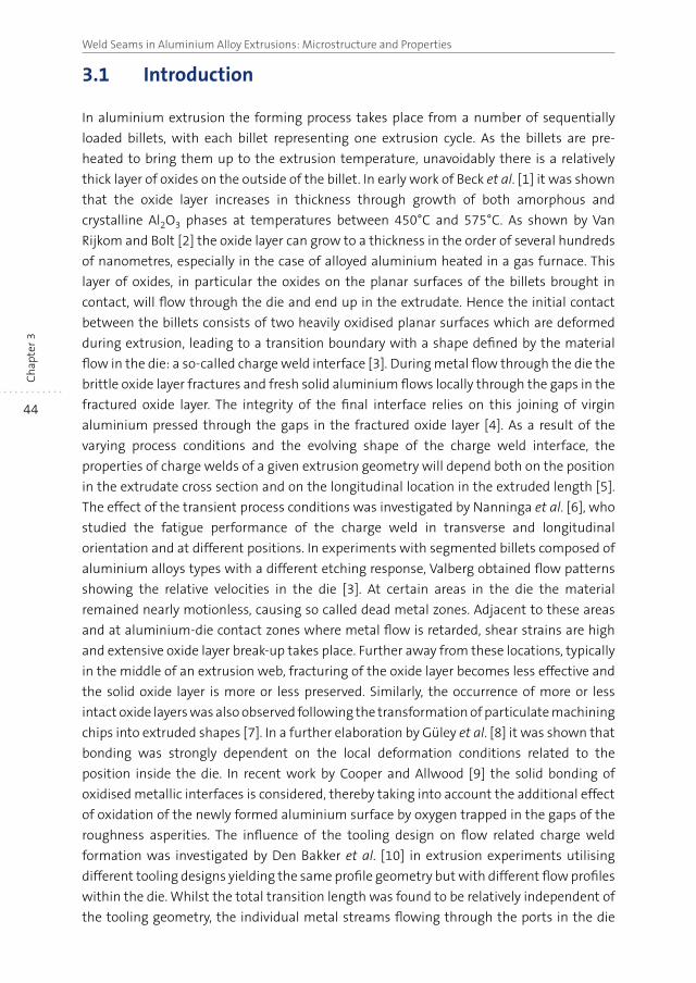
44
Weld Seams in Aluminium Alloy Extrusions: Microstructure and PropertiesC
hap
ter 3
3.1 Introduction
In aluminium extrusion the forming process takes place from a number of sequentially
loaded billets, with each billet representing one extrusion cycle. As the billets are pre-
heated to bring them up to the extrusion temperature, unavoidably there is a relatively
thick layer of oxides on the outside of the billet. In early work of Beck et al. [1] it was shown
that the oxide layer increases in thickness through growth of both amorphous and
crystalline Al2O3 phases at temperatures between 450°C and 575°C. As shown by Van
Rijkom and Bolt [2] the oxide layer can grow to a thickness in the order of several hundreds
of nanometres, especially in the case of alloyed aluminium heated in a gas furnace. This
layer of oxides, in particular the oxides on the planar surfaces of the billets brought in
contact, will flow through the die and end up in the extrudate. Hence the initial contact
between the billets consists of two heavily oxidised planar surfaces which are deformed
during extrusion, leading to a transition boundary with a shape defined by the material
flow in the die: a so-called charge weld interface [3]. During metal flow through the die the
brittle oxide layer fractures and fresh solid aluminium flows locally through the gaps in the
fractured oxide layer. The integrity of the final interface relies on this joining of virgin
aluminium pressed through the gaps in the fractured oxide layer [4]. As a result of the
varying process conditions and the evolving shape of the charge weld interface, the
properties of charge welds of a given extrusion geometry will depend both on the position
in the extrudate cross section and on the longitudinal location in the extruded length [5].
The effect of the transient process conditions was investigated by Nanninga et al. [6], who
studied the fatigue performance of the charge weld in transverse and longitudinal
orientation and at different positions. In experiments with segmented billets composed of
aluminium alloys types with a different etching response, Valberg obtained flow patterns
showing the relative velocities in the die [3]. At certain areas in the die the material
remained nearly motionless, causing so called dead metal zones. Adjacent to these areas
and at aluminium-die contact zones where metal flow is retarded, shear strains are high
and extensive oxide layer break-up takes place. Further away from these locations, typically
in the middle of an extrusion web, fracturing of the oxide layer becomes less effective and
the solid oxide layer is more or less preserved. Similarly, the occurrence of more or less
intact oxide layers was also observed following the transformation of particulate machining
chips into extruded shapes [7]. In a further elaboration by Güley et al. [8] it was shown that
bonding was strongly dependent on the local deformation conditions related to the
position inside the die. In recent work by Cooper and Allwood [9] the solid bonding of
oxidised metallic interfaces is considered, thereby taking into account the additional effect
of oxidation of the newly formed aluminium surface by oxygen trapped in the gaps of the
roughness asperities. The influence of the tooling design on flow related charge weld
formation was investigated by Den Bakker et al. [10] in extrusion experiments utilising
different tooling designs yielding the same profile geometry but with different flow profiles
within the die. Whilst the total transition length was found to be relatively independent of
the tooling geometry, the individual metal streams flowing through the ports in the die
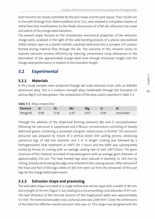
45
Analysis of the structure and mechanical properties of charge welds
Ch
apte
r 3
were found to be closely controlled by the port shape and the port layout. Their results are
in line with findings from Mahmoodkhani et al. [11], who showed in simulation studies of
metal flow that modifications to the feeder dimensions of a flat die influences the onset
and extent of the charge weld transition.
The present paper focuses on the evolutionary mechanical properties of the extrusion
charge weld, analysed in the light of the solid bonding process of a planar, pre-oxidised
brittle surface layer on a ductile metallic substrate deformed into a complex 3-D contour
formed during material flow through the die. The outcome of this research serves to
improve extrusion process efficiency by reducing unnecessary scrap allowances in the
elimination of the approximated charge weld zone through enhanced insight into the
charge weld performance in relation to the transition length.
3.2 Experimental
3.2.1 MaterialsIn this study samples were produced through lab scale extrusion trials with an AA6082
aluminium alloy. This is a medium strength alloy, hardenable through the formation of
various Mg-Si rich precipitates. The composition of the alloy used is reported in Table 3-1.
Table 3-1 Alloy composition
Element Si Fe Mn Mg Cr Al
Weight% 0.98 0.18 0.47 0.67 0.09 remainder
Through the addition of the dispersoid forming elements Mn and Cr recrystallisation
following hot extrusion is suppressed and a fibrous microstructure consisting of heavily
deformed grains containing a recovered sub-grain substructure is formed. The extrusion
precursor was prepared by means of a vertical direct chill casting process, producing
cylindrical logs of 168 mm diameter and 2 m in length. Casting was followed by a
homogenisation heat treatment at 540°C for 5 hours and the billet was subsequently
cooled by forced air cooling with an average cooling rate of over 200°C/hour. The grain
structure of this material consisted of equiaxed grains with an average grain diameter of
approximately 150 μm. The heat treated logs were reduced in diameter to 143 mm by
milling, thereby eliminating the edge zone inherent to the casting process. After removal of
the head and foot of the logs, billets of 300 mm were cut from the remainder of the cast
logs for the charge weld experiments.
3.2.2 Extrusion shape and processingThe extruded shape consisted of a single hollow box-section type with a width of 90 mm
and a height of 35 mm (Figure 3-1a), leading to a circumscribing circle diameter of 97 mm.
The wall thickness of the thinned sections of the longitudinal webs was approximately
5.5 mm. The nominal extrudate cross sectional area was 1340 mm2. Given the dimensions
of the billet the effective overall extrusion ratio was 13. This shape was designed with the
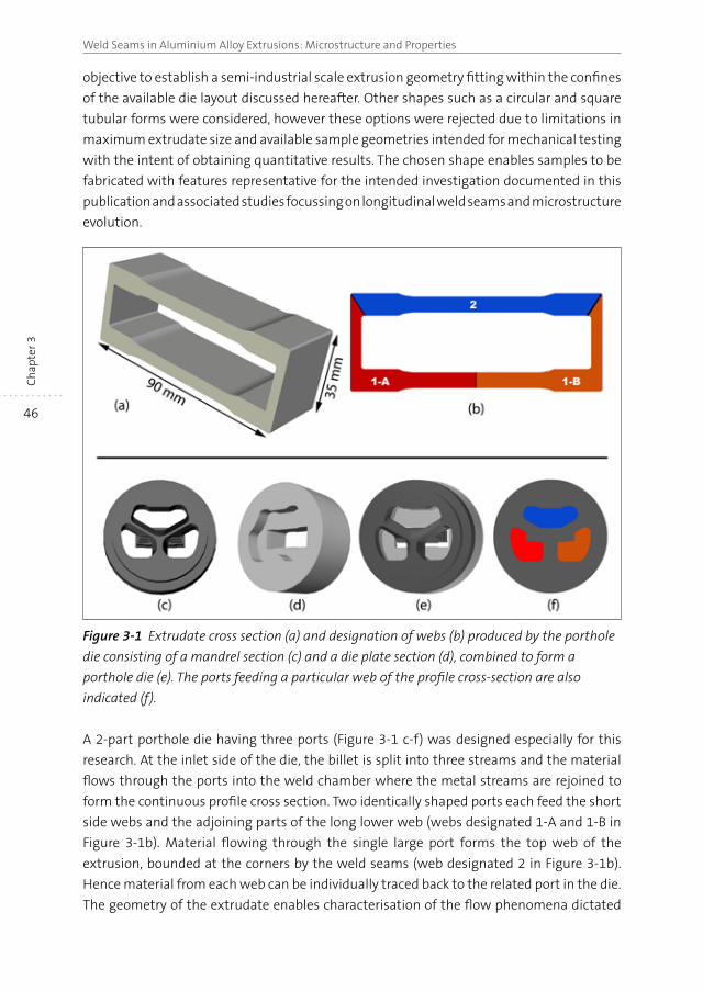
46
Weld Seams in Aluminium Alloy Extrusions: Microstructure and PropertiesC
hap
ter 3
objective to establish a semi-industrial scale extrusion geometry fitting within the confines
of the available die layout discussed hereafter. Other shapes such as a circular and square
tubular forms were considered, however these options were rejected due to limitations in
maximum extrudate size and available sample geometries intended for mechanical testing
with the intent of obtaining quantitative results. The chosen shape enables samples to be
fabricated with features representative for the intended investigation documented in this
publication and associated studies focussing on longitudinal weld seams and microstructure
evolution.
Figure 3-1 Extrudate cross section (a) and designation of webs (b) produced by the porthole
die consisting of a mandrel section (c) and a die plate section (d), combined to form a
porthole die (e). The ports feeding a particular web of the profile cross-section are also
indicated (f).
A 2-part porthole die having three ports (Figure 3-1 c-f) was designed especially for this
research. At the inlet side of the die, the billet is split into three streams and the material
flows through the ports into the weld chamber where the metal streams are rejoined to
form the continuous profile cross section. Two identically shaped ports each feed the short
side webs and the adjoining parts of the long lower web (webs designated 1-A and 1-B in
Figure 3-1b). Material flowing through the single large port forms the top web of the
extrusion, bounded at the corners by the weld seams (web designated 2 in Figure 3-1b).
Hence material from each web can be individually traced back to the related port in the die.
The geometry of the extrudate enables characterisation of the flow phenomena dictated
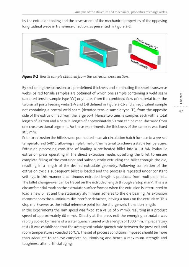
47
Analysis of the structure and mechanical properties of charge welds
Ch
apte
r 3
by the extrusion tooling and the assessment of the mechanical properties of the opposing
longitudinal webs in transverse direction, as presented in Figure 3-2.
Figure 3-2 Tensile sample obtained from the extrusion cross section.
By sectioning the extrusion to a pre-defined thickness and eliminating the short transverse
webs, paired tensile samples are obtained of which one sample containing a weld seam
(denoted tensile sample type ‘W’) originates from the combined flow of material from the
two small ports feeding webs 1-A and 1-B defined in Figure 3-1b and an equivalent sample
not-containing a central weld seam (denoted tensile sample type ‘T’), from the opposite
side of the extrusion fed from the large port. Hence two tensile samples each with a total
length of 90 mm and a parallel length of approximately 50 mm can be manufactured from
one cross-sectional segment. For these experiments the thickness of the samples was fixed
at 5 mm.
Prior to extrusion the billets were pre-heated in an air circulation batch furnace to a pre-set
temperature of 540°C, allowing ample time for the material to achieve a stable temperature.
Extrusion processing consisted of loading a pre-heated billet into a 10 MN hydraulic
extrusion press operating in the direct extrusion mode, upsetting the billet to ensure
complete filling of the container and subsequently extruding the billet through the die,
resulting in a length of the desired extrudate geometry. Following completion of the
extrusion cycle a subsequent billet is loaded and the process is repeated under constant
settings. In this manner a continuous extruded length is produced from multiple billets.
The billet change-over can be traced on the extruded length through a ‘stop mark’. This is a
circumferential mark on the extrudate surface formed when the extrusion is interrupted to
load a new billet and the stationary aluminium adheres to the die bearing. As extrusion
recommences the aluminium-die interface detaches, leaving a mark on the extrudate. This
stop mark serves as the initial reference point for the charge weld transition length.
In the experiments the ram speed was fixed at a value of 5 mm/s, resulting in a product
speed of approximately 60 mm/s. Directly at the press exit the emerging extrudate was
rapidly cooled by means of a water quench tunnel with a length of 1000 mm. In preparatory
tests it was established that the average extrudate quench rate between the press exit and
room temperature exceeded 30°C/s. The set of process conditions imposed should be more
than adequate to achieve complete solutionising and hence a maximum strength and
toughness after artificial aging.
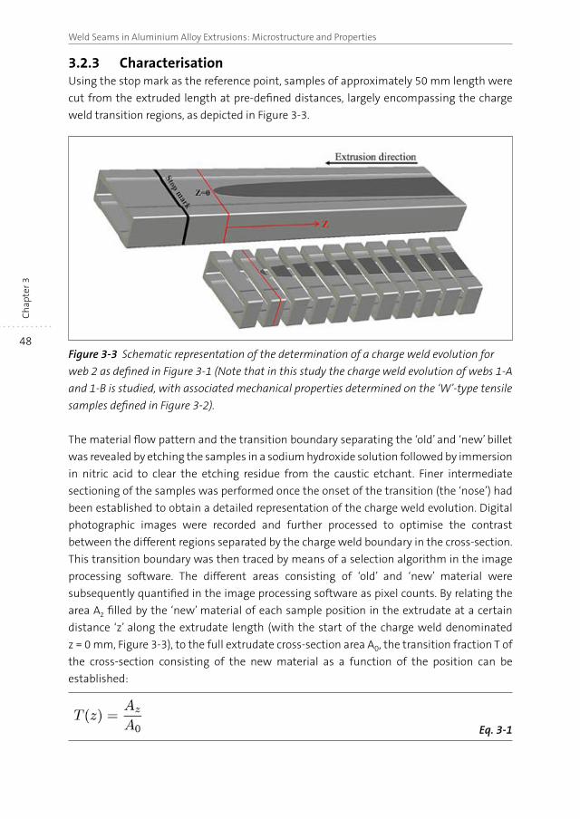
48
Weld Seams in Aluminium Alloy Extrusions: Microstructure and PropertiesC
hap
ter 3
3.2.3 CharacterisationUsing the stop mark as the reference point, samples of approximately 50 mm length were
cut from the extruded length at pre-defined distances, largely encompassing the charge
weld transition regions, as depicted in Figure 3-3.
Figure 3-3 Schematic representation of the determination of a charge weld evolution for
web 2 as defined in Figure 3-1 (Note that in this study the charge weld evolution of webs 1-A
and 1-B is studied, with associated mechanical properties determined on the ‘W’-type tensile
samples defined in Figure 3-2).
The material flow pattern and the transition boundary separating the ‘old’ and ‘new’ billet
was revealed by etching the samples in a sodium hydroxide solution followed by immersion
in nitric acid to clear the etching residue from the caustic etchant. Finer intermediate
sectioning of the samples was performed once the onset of the transition (the ‘nose’) had
been established to obtain a detailed representation of the charge weld evolution. Digital
photographic images were recorded and further processed to optimise the contrast
between the different regions separated by the charge weld boundary in the cross-section.
This transition boundary was then traced by means of a selection algorithm in the image
processing software. The different areas consisting of ‘old’ and ‘new’ material were
subsequently quantified in the image processing software as pixel counts. By relating the
area Az filled by the ‘new’ material of each sample position in the extrudate at a certain
distance ‘z’ along the extrudate length (with the start of the charge weld denominated
z = 0 mm, Figure 3-3), to the full extrudate cross-section area A0, the transition fraction T of
the cross-section consisting of the new material as a function of the position can be
established:
Eq. 3-1
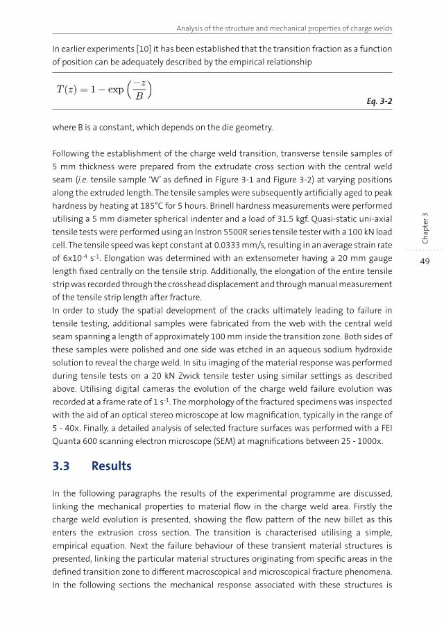
49
Analysis of the structure and mechanical properties of charge welds
Ch
apte
r 3
In earlier experiments [10] it has been established that the transition fraction as a function
of position can be adequately described by the empirical relationship
Eq. 3-2
where B is a constant, which depends on the die geometry.
Following the establishment of the charge weld transition, transverse tensile samples of
5 mm thickness were prepared from the extrudate cross section with the central weld
seam (i.e. tensile sample ‘W’ as defined in Figure 3-1 and Figure 3-2) at varying positions
along the extruded length. The tensile samples were subsequently artificially aged to peak
hardness by heating at 185°C for 5 hours. Brinell hardness measurements were performed
utilising a 5 mm diameter spherical indenter and a load of 31.5 kgf. Quasi-static uni-axial
tensile tests were performed using an Instron 5500R series tensile tester with a 100 kN load
cell. The tensile speed was kept constant at 0.0333 mm/s, resulting in an average strain rate
of 6x10⁻⁴ s-1. Elongation was determined with an extensometer having a 20 mm gauge
length fixed centrally on the tensile strip. Additionally, the elongation of the entire tensile
strip was recorded through the crosshead displacement and through manual measurement
of the tensile strip length after fracture.
In order to study the spatial development of the cracks ultimately leading to failure in
tensile testing, additional samples were fabricated from the web with the central weld
seam spanning a length of approximately 100 mm inside the transition zone. Both sides of
these samples were polished and one side was etched in an aqueous sodium hydroxide
solution to reveal the charge weld. In situ imaging of the material response was performed
during tensile tests on a 20 kN Zwick tensile tester using similar settings as described
above. Utilising digital cameras the evolution of the charge weld failure evolution was
recorded at a frame rate of 1 s-1. The morphology of the fractured specimens was inspected
with the aid of an optical stereo microscope at low magnification, typically in the range of
5 - 40x. Finally, a detailed analysis of selected fracture surfaces was performed with a FEI
Quanta 600 scanning electron microscope (SEM) at magnifications between 25 - 1000x.
3.3 Results
In the following paragraphs the results of the experimental programme are discussed,
linking the mechanical properties to material flow in the charge weld area. Firstly the
charge weld evolution is presented, showing the flow pattern of the new billet as this
enters the extrusion cross section. The transition is characterised utilising a simple,
empirical equation. Next the failure behaviour of these transient material structures is
presented, linking the particular material structures originating from specific areas in the
defined transition zone to different macroscopical and microscopical fracture phenomena.
In the following sections the mechanical response associated with these structures is
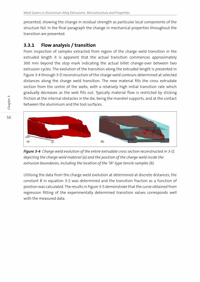
50
Weld Seams in Aluminium Alloy Extrusions: Microstructure and PropertiesC
hap
ter 3
presented, showing the change in residual strength as particular local components of the
structure fail. In the final paragraph the change in mechanical properties throughout the
transition are presented.
3.3.1 Flow analysis / transitionFrom inspection of samples extracted from region of the charge weld transition in the
extruded length it is apparent that the actual transition commences approximately
300 mm beyond the stop mark indicating the actual billet change-over between two
extrusion cycles. The evolution of the transition along the extruded length is presented in
Figure 3-4 through 3-D reconstruction of the charge weld contours determined at selected
distances along the charge weld transition. The new material fills the cross extrudate
section from the centre of the webs, with a relatively high initial transition rate which
gradually decreases as the web fills out. Typically material flow is restricted by sticking
friction at the internal obstacles in the die, being the mandrel supports, and at the contact
between the aluminium and the tool surfaces.
Figure 3-4 Charge weld evolution of the entire extrudate cross section reconstructed in 3-D,
depicting the charge weld material (a) and the position of the charge weld inside the
extrusion boundaries, including the location of the ‘W’-type tensile samples (b).
Utilising the data from the charge weld evolution at determined at discrete distances, the
constant B in equation 3-2 was determined and the transition fraction as a function of
position was calculated. The results in Figure 3-5 demonstrate that the curve obtained from
regression fitting of the experimentally determined transition values corresponds well
with the measured data.
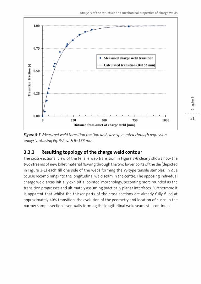
51
Analysis of the structure and mechanical properties of charge welds
Ch
apte
r 3
Figure 3-5 Measured weld transition fraction and curve generated through regression
analysis, utilising Eq. 3-2 with B=133 mm.
3.3.2 Resulting topology of the charge weld contourThe cross-sectional view of the tensile web transition in Figure 3-6 clearly shows how the
two streams of new billet material flowing through the two lower ports of the die (depicted
in Figure 3-1) each fill one side of the webs forming the W-type tensile samples, in due
course recombining into the longitudinal weld seam in the centre. The opposing individual
charge weld areas initially exhibit a ‘pointed’ morphology, becoming more rounded as the
transition progresses and ultimately assuming practically planar interfaces. Furthermore it
is apparent that whilst the thicker parts of the cross sections are already fully filled at
approximately 40% transition, the evolution of the geometry and location of cusps in the
narrow sample section, eventually forming the longitudinal weld seam, still continues.

52
Weld Seams in Aluminium Alloy Extrusions: Microstructure and PropertiesC
hap
ter 3
Figure 3-6 Charge weld evolution of the partial extruded cross section containing the
W-type tensile samples.
In Figure 3-7 details of the charge weld are presented at a transition of 60%. The cusps,
symmetrically located around the longitudinal weld seam, are clearly visible. At higher
magnification the transition boundary is readily observed due to the oxide particles residing
on the transition boundary. The slight undulation of the boundary is thought to be the
effect of the initial surface roughness of the contact surfaces.
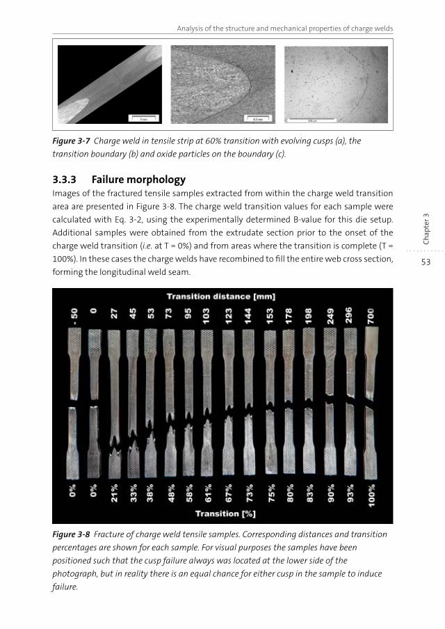
53
Analysis of the structure and mechanical properties of charge welds
Ch
apte
r 3
Figure 3-7 Charge weld in tensile strip at 60% transition with evolving cusps (a), the
transition boundary (b) and oxide particles on the boundary (c).
3.3.3 Failure morphologyImages of the fractured tensile samples extracted from within the charge weld transition
area are presented in Figure 3-8. The charge weld transition values for each sample were
calculated with Eq. 3-2, using the experimentally determined B-value for this die setup.
Additional samples were obtained from the extrudate section prior to the onset of the
charge weld transition (i.e. at T = 0%) and from areas where the transition is complete (T =
100%). In these cases the charge welds have recombined to fill the entire web cross section,
forming the longitudinal weld seam.
Figure 3-8 Fracture of charge weld tensile samples. Corresponding distances and transition
percentages are shown for each sample. For visual purposes the samples have been
positioned such that the cusp failure always was located at the lower side of the
photograph, but in reality there is an equal chance for either cusp in the sample to induce
failure.
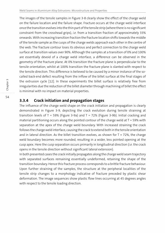
54
Weld Seams in Aluminium Alloy Extrusions: Microstructure and PropertiesC
hap
ter 3
The images of the tensile samples in Figure 3-8 clearly show the effect of the charge weld
on the failure location and the failure shape. Fracture occurs at the charge weld interface
once the transition evolves into the thin part of the tensile strip (where there is no significant
constraint from the crosshead grips), i.e. from a transition fraction of approximately 33%
onwards. With increasing transition fraction the fracture location shifts towards the middle
of the tensile sample as the cusps of the charge welds approach each other in the centre of
the web. The fracture contour loses its obvious and perfect connection to the charge weld
surface at transition values over 90%. Although the samples at a transition of 0% and 100%
are essentially devoid of a charge weld interface, a difference can be observed in the
geometry of the fracture plane. At 0% transition the fracture plane is perpendicular to the
tensile orientation, whilst at 100% transition the fracture plane is slanted with respect to
the tensile direction. This difference is believed to be caused by a minor instance of the so-
called back-end defect resulting from the inflow of the billet surface at the final stages of
the extrusion cycle [12]. In these experiments the billet surface is relatively free from
irregularities due the reduction of the billet diameter through machining of billet the effect
is minimal with no impact on material properties.
3.3.4 Crack initiation and propagation stagesThe influence of the charge weld shape on the crack initiation and propagation is clearly
demonstrated in Figure 3-9, depicting the crack evolution during tensile straining at
transition levels of T = 59% (Figure 3-9a) and T = 72% (Figure 3-9b). Initial cracking and
material partitioning occurs along the pointed contour of the charge weld at T = 59% with
separation at the apex of the charge weld boundary. With increased straining the crack
follows the charge weld interface, causing the crack to extend both in the tensile orientation
and in lateral direction. As the billet transition evolves, as shown for T = 72%, the charge
weld boundary becomes more rounded, resulting in a wider, less pointed opening at the
cusp apex. Here the cusp separation occurs primarily in longitudinal direction (i.e. the crack
opens in the tensile direction without significant lateral extension).
In both presented cases the crack initially propagates along the charge weld seam trajectory
with separated surfaces remaining essentially undeformed, retaining the shape of the
transition boundary. Hence this fracture process corresponds to a brittle fracture behaviour.
Upon further straining of the samples, the structure at the peripheral localities of the
tensile strip changes to a morphology indicative of fracture preceded by plastic shear
deformation. The image sequences show plastic flow lines occurring at 45 degrees angles
with respect to the tensile loading direction.
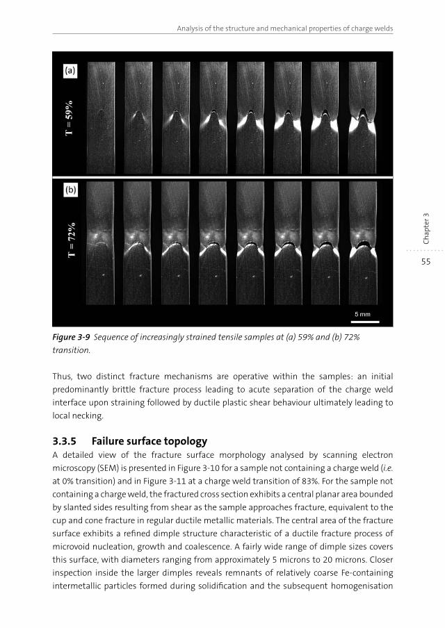
55
Analysis of the structure and mechanical properties of charge welds
Ch
apte
r 3
Figure 3-9 Sequence of increasingly strained tensile samples at (a) 59% and (b) 72%
transition.
Thus, two distinct fracture mechanisms are operative within the samples: an initial
predominantly brittle fracture process leading to acute separation of the charge weld
interface upon straining followed by ductile plastic shear behaviour ultimately leading to
local necking.
3.3.5 Failure surface topologyA detailed view of the fracture surface morphology analysed by scanning electron
microscopy (SEM) is presented in Figure 3-10 for a sample not containing a charge weld (i.e.
at 0% transition) and in Figure 3-11 at a charge weld transition of 83%. For the sample not
containing a charge weld, the fractured cross section exhibits a central planar area bounded
by slanted sides resulting from shear as the sample approaches fracture, equivalent to the
cup and cone fracture in regular ductile metallic materials. The central area of the fracture
surface exhibits a refined dimple structure characteristic of a ductile fracture process of
microvoid nucleation, growth and coalescence. A fairly wide range of dimple sizes covers
this surface, with diameters ranging from approximately 5 microns to 20 microns. Closer
inspection inside the larger dimples reveals remnants of relatively coarse Fe-containing
intermetallic particles formed during solidification and the subsequent homogenisation
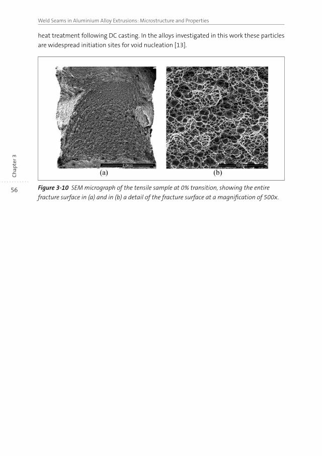
56
Weld Seams in Aluminium Alloy Extrusions: Microstructure and PropertiesC
hap
ter 3
heat treatment following DC casting. In the alloys investigated in this work these particles
are widespread initiation sites for void nucleation [13].
Figure 3-10 SEM micrograph of the tensile sample at 0% transition, showing the entire
fracture surface in (a) and in (b) a detail of the fracture surface at a magnification of 500x.
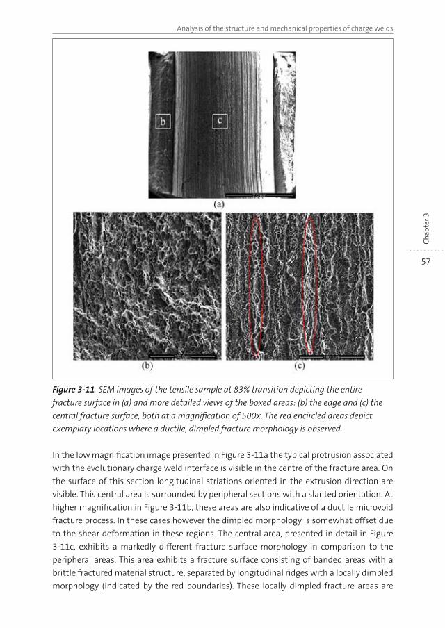
57
Analysis of the structure and mechanical properties of charge welds
Ch
apte
r 3
Figure 3-11 SEM images of the tensile sample at 83% transition depicting the entire
fracture surface in (a) and more detailed views of the boxed areas: (b) the edge and (c) the
central fracture surface, both at a magnification of 500x. The red encircled areas depict
exemplary locations where a ductile, dimpled fracture morphology is observed.
In the low magnification image presented in Figure 3-11a the typical protrusion associated
with the evolutionary charge weld interface is visible in the centre of the fracture area. On
the surface of this section longitudinal striations oriented in the extrusion direction are
visible. This central area is surrounded by peripheral sections with a slanted orientation. At
higher magnification in Figure 3-11b, these areas are also indicative of a ductile microvoid
fracture process. In these cases however the dimpled morphology is somewhat offset due
to the shear deformation in these regions. The central area, presented in detail in Figure
3-11c, exhibits a markedly different fracture surface morphology in comparison to the
peripheral areas. This area exhibits a fracture surface consisting of banded areas with a
brittle fractured material structure, separated by longitudinal ridges with a locally dimpled
morphology (indicated by the red boundaries). These locally dimpled fracture areas are
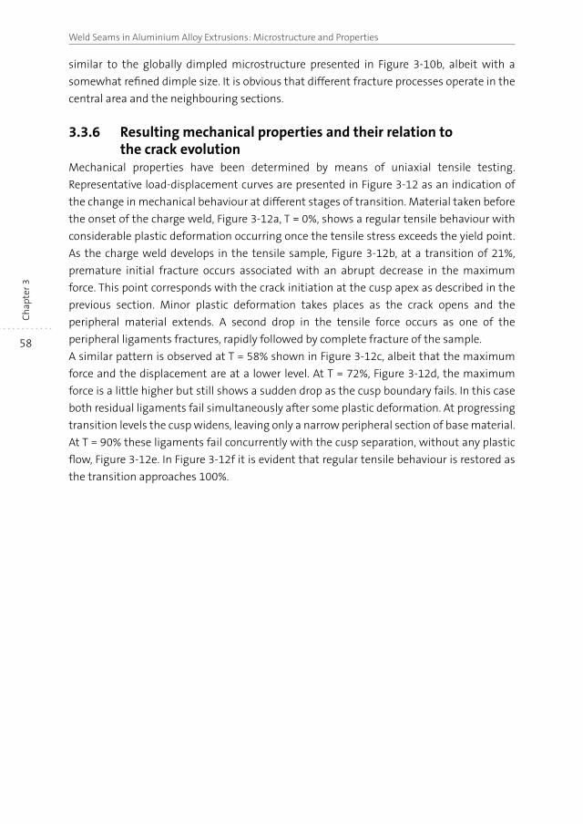
58
Weld Seams in Aluminium Alloy Extrusions: Microstructure and PropertiesC
hap
ter 3
similar to the globally dimpled microstructure presented in Figure 3-10b, albeit with a
somewhat refined dimple size. It is obvious that different fracture processes operate in the
central area and the neighbouring sections.
3.3.6 Resulting mechanical properties and their relation to the crack evolution
Mechanical properties have been determined by means of uniaxial tensile testing.
Representative load-displacement curves are presented in Figure 3-12 as an indication of
the change in mechanical behaviour at different stages of transition. Material taken before
the onset of the charge weld, Figure 3-12a, T = 0%, shows a regular tensile behaviour with
considerable plastic deformation occurring once the tensile stress exceeds the yield point.
As the charge weld develops in the tensile sample, Figure 3-12b, at a transition of 21%,
premature initial fracture occurs associated with an abrupt decrease in the maximum
force. This point corresponds with the crack initiation at the cusp apex as described in the
previous section. Minor plastic deformation takes places as the crack opens and the
peripheral material extends. A second drop in the tensile force occurs as one of the
peripheral ligaments fractures, rapidly followed by complete fracture of the sample.
A similar pattern is observed at T = 58% shown in Figure 3-12c, albeit that the maximum
force and the displacement are at a lower level. At T = 72%, Figure 3-12d, the maximum
force is a little higher but still shows a sudden drop as the cusp boundary fails. In this case
both residual ligaments fail simultaneously after some plastic deformation. At progressing
transition levels the cusp widens, leaving only a narrow peripheral section of base material.
At T = 90% these ligaments fail concurrently with the cusp separation, without any plastic
flow, Figure 3-12e. In Figure 3-12f it is evident that regular tensile behaviour is restored as
the transition approaches 100%.
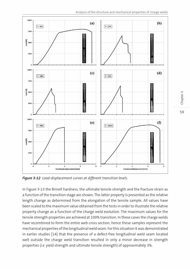
59
Analysis of the structure and mechanical properties of charge welds
Ch
apte
r 3Figure 3-12 Load-displacement curves at different transition levels.
In Figure 3-13 the Brinell hardness, the ultimate tensile strength and the fracture strain as
a function of the transition stage are shown. The latter property is presented as the relative
length change as determined from the elongation of the tensile sample. All values have
been scaled to the maximum value obtained from the tests in order to illustrate the relative
property change as a function of the charge weld evolution. The maximum values for the
tensile strength properties are achieved at 100% transition. In these cases the charge welds
have recombined to form the entire web cross section, hence these samples represent the
mechanical properties of the longitudinal weld seam. For this situation it was demonstrated
in earlier studies [14] that the presence of a defect-free longitudinal weld seam located
well outside the charge weld transition resulted in only a minor decrease in strength
properties (i.e. yield strength and ultimate tensile strength) of approximately 3%.
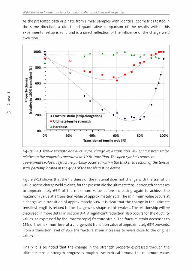
60
Weld Seams in Aluminium Alloy Extrusions: Microstructure and PropertiesC
hap
ter 3
As the presented data originate from similar samples with identical geometries tested in
the same direction, a direct and quantitative comparison of the results within this
experimental setup is valid and is a direct reflection of the influence of the charge weld
evolution.
Figure 3-13 Tensile strength and ductility vs. charge weld transition. Values have been scaled
relative to the properties measured at 100% transition. The open symbols represent
approximate values, as fracture partially occurred within the thickened section of the tensile
strip, partially located in the grips of the tensile testing device.
Figure 3-13 shows that the hardness of the material does not change with the transition
value. As the charge weld evolves, for the present die the ultimate tensile strength decreases
to approximately 65% of the maximum value before increasing again to achieve the
maximum value at a transition value of approximately 95%. The minimum value occurs at
a charge weld transition of approximately 60%. It is clear that the change in the ultimate
tensile strength is related to the charge weld shape as this evolves. The relationship will be
discussed in more detail in section 3-4. A significant reduction also occurs for the ductility
values, as expressed by the (macroscopic) fracture strain. The fracture strain decreases to
15% of the maximum level at a charge weld transition value of approximately 65% onwards.
From a transition level of 85% the fracture strain increases to levels close to the original
values.
Finally it is be noted that the change in the strength property expressed through the
ultimate tensile strength progresses roughly symmetrical around the minimum value,
61
Analysis of the structure and mechanical properties of charge welds
Ch
apte
r 3
whilst the tensile fracture strain determined through the crosshead displacement exhibits
a distinct non-symmetrical distribution.
3.4 Discussion
As clearly documented in the results section above the charge weld is a transient
phenomenon, typified by the amount of ‘new’ billet material filling the extrudate cross
section. Transition occurs rapidly at first and then gradually slows at the charge weld
merges with the longitudinal weld seam. Within the charge weld transition the bond
strength exhibits a roughly symmetrical decline with position in the weld seam region,
whilst the ductility, as expressed by the strain at fracture, exhibits an asymmetrical
dependence. From the constant hardness values it can be concluded that the change in
properties cannot be ascribed to inappropriate thermal conditions resulting in an
unfavourable precipitate distribution.
The tensile failure behaviour is controlled through two factors: the material characteristics
influenced by the charge weld boundary and the operative stress condition during tensile
loading. Considering the latter, the imposed force on the sample causes a pure tensile
stress at the cusp apex, gradually changing to a more shear dominated stress condition
towards the periphery of the charge weld. This changing stress condition contributes to the
failure process: initiation at the cusp apex due to high tensile forces, next continued failure
along the cusp boundary as the shear component increases and ultimately failing of the
ductile peripheral ligaments due to tensile loading. As the charge weld evolves the shape of
the charge weld changes from a relatively pointed morphology to a more rounded shape.
This infers that in the latter case a higher contribution of the tensile stress component
occurs, with failure initiation occurring at lower global tensile forces. In contrast, the
strength increases after a transition of 60%, i.e. at a point where the charge weld cusp
morphology increasingly attains a more rounded shape. Hence the effects of the charge
weld on the behaviour and properties appear to be dominated by the interface properties.
The behaviour of the charge weld interface will now analysed as if it was a layered bulk
composite structure with a single particulate populated interface having properties
proportional to the particle coverage.
3.4.1 Tensile strength vs. oxide particle distributionThe inhomogeneous deformation in the die causes a variation in the oxide fragment
distribution and as a result the associated joining of metallic interface transversely to the
extrusion. The experimental results show that inferior bonding occurs at the central portion
of web where deformation during forming is low, whilst away from the middle of the web,
the bonding performance improves. The low cohesive boundary strength correlates well
with the earlier discussed solid bonding concept of a minimum deformation required to
achieve bonding and rising bond strengths with increased deformation.
62
Weld Seams in Aluminium Alloy Extrusions: Microstructure and PropertiesC
hap
ter 3
To make a first order approximation of the influence of oxide particles distribution on the
strength of the bond plane, the charge weld is considered as a ‘local’ metal sandwich/
laminate structure with the charge weld cusp bonded to the surrounding regular material
through an interface populated by a particulate metal oxide distribution. The total strength
is a factored combination of well-bonded peripheral areas and the charge weld bond area.
In the latter area the bond strength is proportional with the net effective bond area An
given in Eq. 3-3:
Eq. 3-3
where Ac denotes the nominal contact area Ap is the area populated by the fractured oxide
particles. Aox the newly formed, but re-oxidised area as defined in the work by Cooper and
Allwood [9]. In the situation addressed in this study all entrapped oxygen is however
confined to asperity gaps formed by the oxide layers, hence any trapped oxygen remains
essentially isolated from the virgin aluminium surface. Therefore in this case it is believed
that a negligible fraction of the oxygen could result in additional oxidation, i.e. Aox≈0.
The strength of a laminate structure is proposed to given by the rule of mixtures [15]:
Eq. 3-4
where σ and f indicate the tensile stress and area fraction of the tensile fracture surface,
and subscripts tot, b and cw stand for the composite sample, the base metal and the charge
weld interface respectively (note that fb + fcw = 1).
The transverse tensile strength of the base metal, σb was obtained from the tensile
properties of samples outside the transition region and was found to be σb = 337 MPa. The
area fractions were obtained from width and thickness measurements of the fracture areas
of the tensile samples, e.g. the ratio of the different areas as visible in Figure 3-11a. Utilising
this data the strength σcw of the charge weld can be calculated from Eq. 3-4. Assuming that
the area fraction An/Ac of the charge weld cusp is equally represented by the ratio of the
base metal strength and the charge weld material strength, An is calculated:
Eq. 3-5
The difference between the bond area Ac determined from the cross-sectional cusp area of
the fractured samples and the net bond area An calculated from Eq. 3-5 represents the non-
bonded, oxidised surface. The results are presented in Figure 3-14, showing the charge weld
strength and the ultimate tensile strength of the samples versus the transition (data is
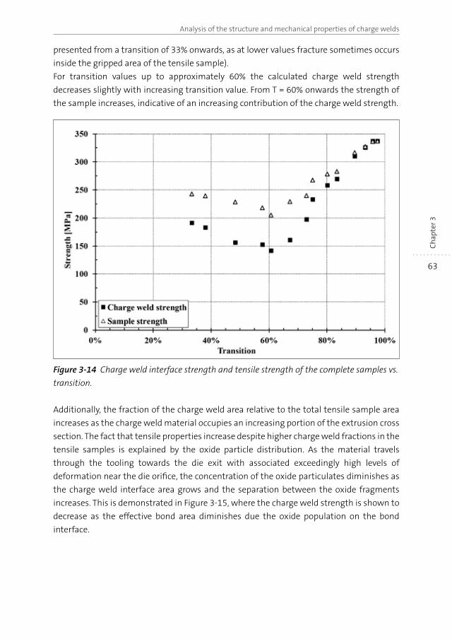
63
Analysis of the structure and mechanical properties of charge welds
Ch
apte
r 3
presented from a transition of 33% onwards, as at lower values fracture sometimes occurs
inside the gripped area of the tensile sample).
For transition values up to approximately 60% the calculated charge weld strength
decreases slightly with increasing transition value. From T = 60% onwards the strength of
the sample increases, indicative of an increasing contribution of the charge weld strength.
Figure 3-14 Charge weld interface strength and tensile strength of the complete samples vs.
transition.
Additionally, the fraction of the charge weld area relative to the total tensile sample area
increases as the charge weld material occupies an increasing portion of the extrusion cross
section. The fact that tensile properties increase despite higher charge weld fractions in the
tensile samples is explained by the oxide particle distribution. As the material travels
through the tooling towards the die exit with associated exceedingly high levels of
deformation near the die orifice, the concentration of the oxide particulates diminishes as
the charge weld interface area grows and the separation between the oxide fragments
increases. This is demonstrated in Figure 3-15, where the charge weld strength is shown to
decrease as the effective bond area diminishes due the oxide population on the bond
interface.
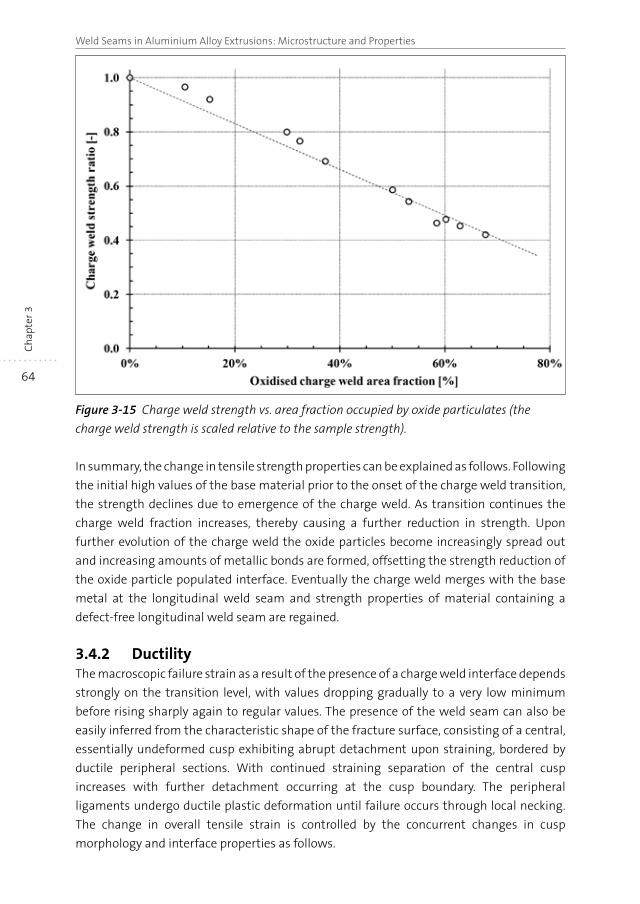
64
Weld Seams in Aluminium Alloy Extrusions: Microstructure and PropertiesC
hap
ter 3
Figure 3-15 Charge weld strength vs. area fraction occupied by oxide particulates (the
charge weld strength is scaled relative to the sample strength).
In summary, the change in tensile strength properties can be explained as follows. Following
the initial high values of the base material prior to the onset of the charge weld transition,
the strength declines due to emergence of the charge weld. As transition continues the
charge weld fraction increases, thereby causing a further reduction in strength. Upon
further evolution of the charge weld the oxide particles become increasingly spread out
and increasing amounts of metallic bonds are formed, offsetting the strength reduction of
the oxide particle populated interface. Eventually the charge weld merges with the base
metal at the longitudinal weld seam and strength properties of material containing a
defect-free longitudinal weld seam are regained.
3.4.2 DuctilityThe macroscopic failure strain as a result of the presence of a charge weld interface depends
strongly on the transition level, with values dropping gradually to a very low minimum
before rising sharply again to regular values. The presence of the weld seam can also be
easily inferred from the characteristic shape of the fracture surface, consisting of a central,
essentially undeformed cusp exhibiting abrupt detachment upon straining, bordered by
ductile peripheral sections. With continued straining separation of the central cusp
increases with further detachment occurring at the cusp boundary. The peripheral
ligaments undergo ductile plastic deformation until failure occurs through local necking.
The change in overall tensile strain is controlled by the concurrent changes in cusp
morphology and interface properties as follows.
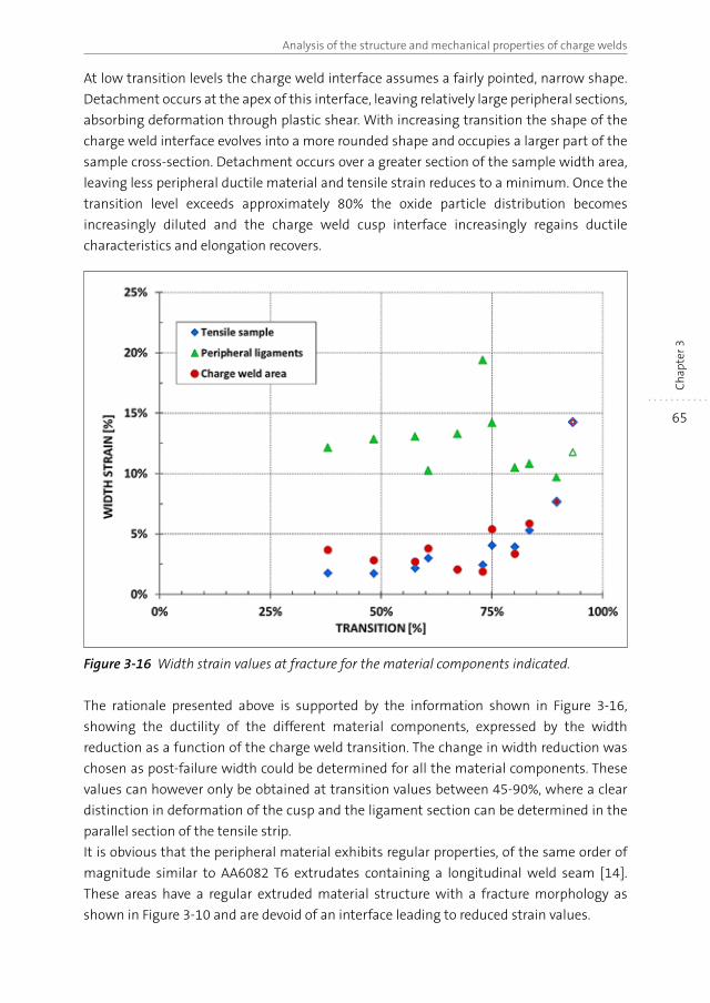
65
Analysis of the structure and mechanical properties of charge welds
Ch
apte
r 3
At low transition levels the charge weld interface assumes a fairly pointed, narrow shape.
Detachment occurs at the apex of this interface, leaving relatively large peripheral sections,
absorbing deformation through plastic shear. With increasing transition the shape of the
charge weld interface evolves into a more rounded shape and occupies a larger part of the
sample cross-section. Detachment occurs over a greater section of the sample width area,
leaving less peripheral ductile material and tensile strain reduces to a minimum. Once the
transition level exceeds approximately 80% the oxide particle distribution becomes
increasingly diluted and the charge weld cusp interface increasingly regains ductile
characteristics and elongation recovers.
Figure 3-16 Width strain values at fracture for the material components indicated.
The rationale presented above is supported by the information shown in Figure 3-16,
showing the ductility of the different material components, expressed by the width
reduction as a function of the charge weld transition. The change in width reduction was
chosen as post-failure width could be determined for all the material components. These
values can however only be obtained at transition values between 45-90%, where a clear
distinction in deformation of the cusp and the ligament section can be determined in the
parallel section of the tensile strip.
It is obvious that the peripheral material exhibits regular properties, of the same order of
magnitude similar to AA6082 T6 extrudates containing a longitudinal weld seam [14].
These areas have a regular extruded material structure with a fracture morphology as
shown in Figure 3-10 and are devoid of an interface leading to reduced strain values.
66
Weld Seams in Aluminium Alloy Extrusions: Microstructure and PropertiesC
hap
ter 3
In contrast, the local failure strains in the central area containing the charge weld interface
are much lower. The change in the charge weld width strain progresses roughly in the same
manner as the bulk width strain determined for the entire tensile sample. The ductility
values in the charge weld area result from early boundary separation at the cusp apex. This
brittle fracture behaviour is a direct result of the oxide particles residing on the boundary
interface. Despite the heavily reduced deformation capacity due to this charge weld
separation, integrity of the sample during straining is upheld through the ductile
deformation properties of the peripheral ligaments.
The change in the bulk fracture strain values as a function of the charge weld transition
shown in Figure 3-16 is therefore be considered to be the combined effect of two
microstructural components: i) peripheral ligaments with a constant, high ductility and ii)
a brittle central charge weld interface. At low transition values, deformation is absorbed
primarily by the relatively large area fraction of the ligament zones. As transition progresses
the contribution of the ligaments diminishes, leading to lower strain values. As transition
levels increase further, the charge weld interface deformability increases as the oxide
particle coverage is reduced and increasingly ductile deformation characteristics of the
charge weld area are achieved.
3.5 Conclusions
In this study the evolutionary morphology and the associated mechanical properties of
extrusion charge welds were studied. Serial sectioning of samples spanning the charge
weld transition in sample lengths of a specifically designed test extrudate showed that the
failure behaviour and properties are controlled by the interfacial oxide particle distribution
resulting from the flow deformation of the initially planar oxidised billet contact areas. In-
situ imaging of crack initiation and propagation as a function of the charge weld interface
state provided additional insight into the factors controlling the strength and ductility
properties. The very low cohesive strength of the densely populated oxide particle interface
of the cross section causes the strength and ductility of the material to decline. Abrupt
separation of the interface occurs, resulting in low bulk fracture strains. It is however
demonstrated that the ductile properties of the bulk material are unaffected and ductility
reduction is solely caused by the abrupt de-cohesion of the local charge weld interface due
to the particulate oxides being present on the boundary between the initial planar surfaces
of consecutively processed billets. The oxide particulates become more widely dispersed as
the charge weld evolves and properties increase again, eventually reaching the original
values.
The concept of a composite material structure bounded by an evolutionary oxide particle
populated interface may be further elaborated and implemented in an algorithm aimed at
predicting the charge weld performance of arbitrary shapes where material flow is dictated
by the die geometry. In this study a previously developed analytical description of the
charge weld evolution was utilised. This empirical equation is utilises a single parameter, in
67
Analysis of the structure and mechanical properties of charge welds
Ch
apte
r 3
this work denoted as B, which needs to be determined for each die. Once this parameter
has been established, the transition can be calculated, and utilising the concept of an
evolving oxide-particulate populated interface, the properties of the charge weld at each
longitudinal position in the extrudate can be predicted. Further work is therefore envisaged,
focussing on material flow in relation to the constant B utilising numerical techniques with
additional experimental support.
3.6 References
[1] A.F. Beck, M.A. Heine, E.J. Caule, M.J. Pryor, Corrosion Science, 7 (1967), pp. 1-22.
[2] J. Van Rijkom, P.H. Bolt, Seventh International Aluminum Extrusion Technology Seminar,
The Aluminum Association, Chicago, IL, USA, 2000, pp. 249-260.
[3] H. Valberg, Int. J. Mater. Prod. Tec., 17 (2002), pp. 497-556.
[4] H.A. Mohamed, J. Washburn, Weld. J. (Miami), 54 (1975), pp. 302-310.
[5] R. Akeret, Journal of the Institute of Metals, 100 (1972), pp. 202-208.
[6] N.E. Nanninga, C. White, R. Dickson, Journal of Materials Engineering and Performance,
20 (2011), pp. 1235-1241.
[7] A.E. Tekkaya, M. Schikorra, D. Becker, D. Biermann, N. Hammer, K. Pantke, J. Mater. Process.
Tech., 209 (2009), pp. 3343-3350.
[8] V. Güley, A. Güzel, A. Jäger, N. Ben Khalifa, A.E. Tekkaya, W.Z. Misiolek, Materials Science
and Engineering A, 574 (2013), pp. 163-175.
[9] D.R. Cooper, J.M. Allwood, J. Mater. Process. Tech., 214, (2014), pp. 2576-2692
[10] A.J. Den Bakker, R.J. Werkhoven, R. Van der Nolle, in: E. Tekkaya, A. Jäger (Eds.) ICEB
2013-International Conference on Extrusion and Benchmark, Dortmund, Germany, 2013,
pp. 57-64.
[11] Y. Mahmoodkhani, M.A. Wells, N. Parson, W.J. Poole, J. Mater. Process. Tech., 214 (2014),
pp. 688-700.
[12] V.I. Johannes, C.W. Jowett, R.F. Dickson, Sixth International Aluminum Extrusion
Technology Seminar, Aluminum Association, Chicago, IL, USA, 1996, pp. 89-94.
[13] D. Lassance, Modeling of damage mechanisms in AlMgSi alloys, Doctoral Thesis,
Institute of Mechanic, Materials and Civil Engineering, Universite Catholique de Louvain,
2006.
[14] A.J. Den Bakker, X. Ma, L. Katgerman, S. v.d. Zwaag, Mater. Sci. Tech. Ser., 31 (2015),
pp. 94-104.
[15] D.N. Lee, Y.K. Kim, J. Mater. Sci., 23 (1988), pp. 558-564.

CHAPTER 4
Microstructure and properties of longitudinal weld seams in aluminium alloy extrusions
Abstract
In this chapter the structure and mechanical properties of aluminium extrusions containing
high quality defect-free longitudinal weld seams are investigated. The extrusions are produced
on a laboratory extrusion press under closely controlled conditions. By utilising a specially
designed die, extruded box-section samples are obtained containing webs with and without
longitudinal weld seams produced simultaneously and under identical conditions. The
resulting samples are characterised by means of mechanical testing and microstructural
assessments. It is concluded that the failure strain for non-recrystallised material is susceptible
to the presence of a weld seam, whilst in fully recrystallised material both failure strength,
failure strain and Charpy impact strength are unaffected. These differences in behaviour are
shown to be related to the presence or absence of specific crystallographic texture components
and gradients near the weld seam.
70
Weld Seams in Aluminium Alloy Extrusions: Microstructure and PropertiesC
hap
ter 4
4.1 Introduction
It is well known (but poorly understood why), that the microstructure and associated
properties of longitudinal weld seams in hollow aluminium extrusions produced by means
of porthole dies and bridge dies may or may not differ from the those of parts of the
extrudate not containing a weld seam. To enable the use of hollow aluminium extrudates
in critical structural components, it is crucial to be sure that the mechanical properties, the
tensile strength, the failure strain and the Charpy impact strength of segments of the
extrudate containing a weld seam do not differ significantly from those of the bulk material.
Hence it is important to determine the conditions leading to weld seams with equal or
lower mechanical properties.
The particulars of extrusion weld seams have been addressed by several researchers. In
early publications, focus was directed on the mechanical process of solid bonding, [1].
Akeret [2] presented the approximate criteria for sound weld seams and validated the
criteria by experimental results. The weld seam performance was primarily related to the
local extrusion ratio of the specific die geometries. In later publications, several types of
more sophisticated weld seam quality indicators were developed. These criteria mostly
centred on the mechanical process of weld seam formation, and were linked to the local
pressure on the bond interface and the bonding time in the die [3-7]. As the direct validation
of the criteria is generally hard to make, the validation of the models is often indirect via
numerical models for the extrusion of hollow products [3, 8-21]. Unfortunately the
developed bond criteria are restricted to a fixed tooling geometry and were found to be
valid within a limited range of alloy compositions only.
As weld seam formation is closely controlled by metal flow within the die, this topic was
extensively investigated, both by means of model materials and though aluminium
extrusion experiments utilising dedicated dies [22-28]. In particular, the findings by Akeret
[29] and Valberg [27] are informative for defective weld seams. In these studies weld seams
defects related to metal flow behaviour were described. Cases are described where
predominantly insufficient metal feeding occurred, leading to non-bonded weld areas.
Inferior bond quality is due to non-optimal convergence of metal streams, leaving oxygen
containing pockets downstream of the mandrel supports. These so-called kissing bonds
[30] having a tensile stress and strain much lower than the base material are very
detrimental for the quality of hollow aluminium products and are also difficult to detect.
Without exception, the predictive methods for determining the performance longitudinal
weld seams outlined above treat the material as a continuum structure, discounting the
evolutionary microstructural features resulting from the hot deformation of the aluminium
alloys. However, other more metallurgical studies on aluminium extrusions have shown
that the alloy response to extensive hot forming is greatly influenced by the local
deformation conditions, giving rise to specific microstructures and rather different
mechanical properties. The response depends directly on the alloy composition as well as
the thermal treatments after extrusion. Precipitate forming elements in the age hardenable
alloys control the strength properties of the material, whilst dispersoid forming elements
71
Microstructure and properties of longitudinal weld seams
Ch
apte
r 4
predominantly influence the grain structure during and directly after hot deformation. In
dispersoid containing aluminium alloys recrystallisation is suppressed, leaving a structure
with grains deformed in line with the metal flow in the die [31]. In the absence of dispersoids
recrystallisation will erase such deformation structures. The mode and extent of
recrystallisation depends on the local conditions in the extrusion tooling, hence different
grain structures can form within a single extrusion cross-section [32, 33]. In addition
specific crystallographic textures may be formed leading to anisotropy in the mechanical
behaviour [34]. In studies on extruded AA6063, evolving into a recrystallised structure with
a cube texture, and AA6082, retaining a fibrous, non recrystallised grain morphology with a
ß-fibre texture, it was shown that the recrystallised material has highly superior formability
characteristics in comparison with the fibrous AA6082 alloy although the strength values
were not very different [34, 35]. These properties were determined in the W-temper, i.e.
prior to any precipitation heat treatment operations customarily applied to these alloys to
achieve enhanced strength values. It is well known that precipitation treatments cause an
important change in the ductility and associated formability characteristics [36], especially
in the case of dispersoid-free alloys [37-39].
In simple geometries, such as extruded flats, the grain structure and crystallographic
texture are nicely correlated to the mechanical properties. In contrast, complex extrudate
geometries result in asymmetrical, complex microstructural distributions with associated
variations in deformation behaviour [40]. It was further demonstrated that the formability
is primarily controlled by grains with a ‘soft’ crystallographic orientation, i.e. strain is
localised to soft regions. Specifically for extrusions produced by means of porthole dies the
complex, 3-D material flow can result in local regions in the vicinity of the weld seam with
different crystallographic textures, combined with regions containing randomly oriented
grains, negatively affecting the weld seam mechanical properties [41]. In research by
Yasuda et. al [42], reduced ductility of samples containing a weld seam was determined in
high temperature tensile tests on a 6xxx-series plate extruded by means of a port-hole die.
Weld seam-containing specimens exhibited pronounced localised deformation near the
weld seam.
It is evident that the presence of a longitudinal weld seam is an important factor influencing
the properties of extruded sections, both in terms of post-extrusion forming operations
and the mechanical integrity of heavily loaded constructions consisting of aluminium alloy
extrusions. In this work, the characteristics of extrusions containing longitudinal weld
seams are studied in relation to the specific microstructures and crystallographic textures
controlled by alloy composition and processing parameters. It should be emphasized that
the test samples in this study contain ‘perfect’, defect-free weld seams, i.e. without
inclusions, kissing bonds and other metal flow-related avoidable structures negatively
affecting the performance of longitudinal weld seams. From a process engineering
perspective the weld seams are as good as they can be made. In the research presented in
this chapter we focus on well-defined weld seams made in both a recrystallising and non-
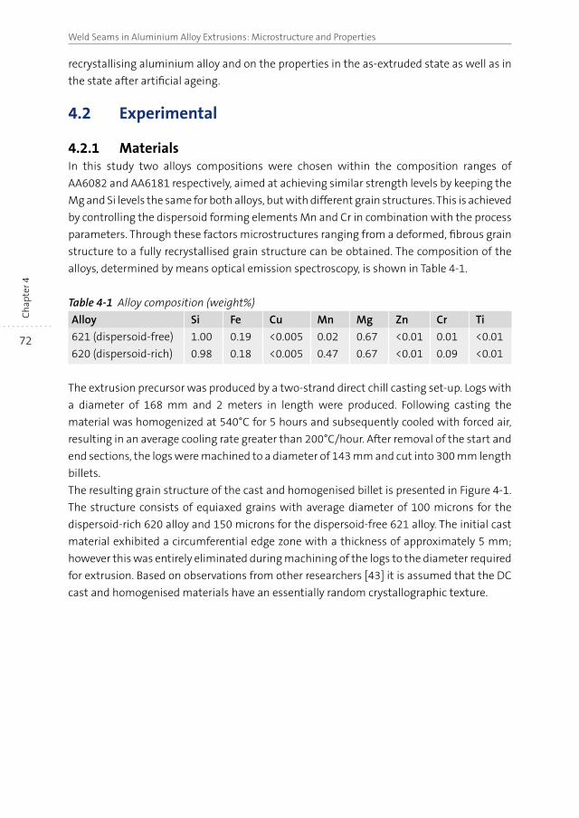
72
Weld Seams in Aluminium Alloy Extrusions: Microstructure and PropertiesC
hap
ter 4
recrystallising aluminium alloy and on the properties in the as-extruded state as well as in
the state after artificial ageing.
4.2 Experimental
4.2.1 MaterialsIn this study two alloys compositions were chosen within the composition ranges of
AA6082 and AA6181 respectively, aimed at achieving similar strength levels by keeping the
Mg and Si levels the same for both alloys, but with different grain structures. This is achieved
by controlling the dispersoid forming elements Mn and Cr in combination with the process
parameters. Through these factors microstructures ranging from a deformed, fibrous grain
structure to a fully recrystallised grain structure can be obtained. The composition of the
alloys, determined by means optical emission spectroscopy, is shown in Table 4-1.
Table 4-1 Alloy composition (weight%)
Alloy Si Fe Cu Mn Mg Zn Cr Ti
621 (dispersoid-free) 1.00 0.19 <0.005 0.02 0.67 <0.01 0.01 <0.01
620 (dispersoid-rich) 0.98 0.18 <0.005 0.47 0.67 <0.01 0.09 <0.01
The extrusion precursor was produced by a two-strand direct chill casting set-up. Logs with
a diameter of 168 mm and 2 meters in length were produced. Following casting the
material was homogenized at 540°C for 5 hours and subsequently cooled with forced air,
resulting in an average cooling rate greater than 200°C/hour. After removal of the start and
end sections, the logs were machined to a diameter of 143 mm and cut into 300 mm length
billets.
The resulting grain structure of the cast and homogenised billet is presented in Figure 4-1.
The structure consists of equiaxed grains with average diameter of 100 microns for the
dispersoid-rich 620 alloy and 150 microns for the dispersoid-free 621 alloy. The initial cast
material exhibited a circumferential edge zone with a thickness of approximately 5 mm;
however this was entirely eliminated during machining of the logs to the diameter required
for extrusion. Based on observations from other researchers [43] it is assumed that the DC
cast and homogenised materials have an essentially random crystallographic texture.
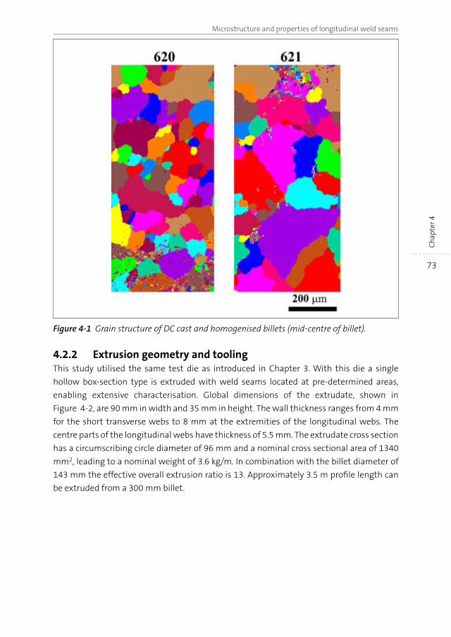
73
Microstructure and properties of longitudinal weld seams
Ch
apte
r 4
Figure 4-1 Grain structure of DC cast and homogenised billets (mid-centre of billet).
4.2.2 Extrusion geometry and toolingThis study utilised the same test die as introduced in Chapter 3. With this die a single
hollow box-section type is extruded with weld seams located at pre-determined areas,
enabling extensive characterisation. Global dimensions of the extrudate, shown in
Figure 4-2, are 90 mm in width and 35 mm in height. The wall thickness ranges from 4 mm
for the short transverse webs to 8 mm at the extremities of the longitudinal webs. The
centre parts of the longitudinal webs have thickness of 5.5 mm. The extrudate cross section
has a circumscribing circle diameter of 96 mm and a nominal cross sectional area of 1340
mm2, leading to a nominal weight of 3.6 kg/m. In combination with the billet diameter of
143 mm the effective overall extrusion ratio is 13. Approximately 3.5 m profile length can
be extruded from a 300 mm billet.
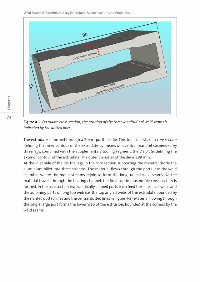
74
Weld Seams in Aluminium Alloy Extrusions: Microstructure and PropertiesC
hap
ter 4
Figure 4-2 Extrudate cross section; the position of the three longitudinal weld seams is
indicated by the dotted lines.
The extrudate is formed through a 2-part porthole die. This tool consists of a core section
defining the inner contour of the extrudate by means of a central mandrel suspended by
three legs, combined with the supplementary tooling segment, the die plate, defining the
exterior contour of the extrudate. The outer diameter of the die is 189 mm.
At the inlet side of the die the legs in the core section supporting the mandrel divide the
aluminium billet into three streams. The material flows through the ports into the weld
chamber where the metal streams rejoin to form the longitudinal weld seams. As the
material travels through the bearing channel, the final continuous profile cross section is
formed. In the core section two identically shaped ports each feed the short side webs and
the adjoining parts of long top web (i.e. the top angled webs of the extrudate bounded by
the slanted dotted lines and the central dotted lines in Figure 4-2). Material flowing through
the single large port forms the lower web of the extrusion, bounded at the corners by the
weld seams.
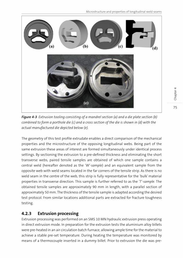
75
Microstructure and properties of longitudinal weld seams
Ch
apte
r 4
Figure 4-3 Extrusion tooling consisting of a mandrel section (a) and a die plate section (b)
combined to form a porthole die (c) and a cross section of the die is shown in (d) with the
actual manufactured die depicted below (e).
The geometry of this test profile extrudate enables a direct comparison of the mechanical
properties and the microstructure of the opposing longitudinal webs. Being part of the
same extrusion these areas of interest are formed simultaneously under identical process
settings. By sectioning the extrusion to a pre-defined thickness and eliminating the short
transverse webs, paired tensile samples are obtained of which one sample contains a
central weld (hereafter denoted as the ‘W’-sample) and an equivalent sample from the
opposite web with weld seams located in the far corners of the tensile strip. As there is no
weld seam in the centre of the web, this strip is fully representative for the ‘bulk’ material
properties in transverse direction. This sample is further referred to as the ‘T’-sample. The
obtained tensile samples are approximately 90 mm in length, with a parallel section of
approximately 50 mm. The thickness of the tensile sample is adapted according the desired
test protocol. From similar locations additional parts are extracted for fracture toughness
testing.
4.2.3 Extrusion processingExtrusion processing was performed on an SMS 10 MN hydraulic extrusion press operating
in direct extrusion mode. In preparation for the extrusion tests the aluminium alloy billets
were pre-heated in an air circulation batch furnace, allowing ample time for the material to
achieve a stable pre-set temperature. During heating the temperature was monitored by
means of a thermocouple inserted in a dummy billet. Prior to extrusion the die was pre-
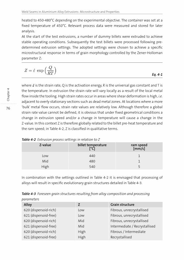
76
Weld Seams in Aluminium Alloy Extrusions: Microstructure and PropertiesC
hap
ter 4
heated to 450-480°C depending on the experimental objective. The container was set at a
fixed temperature of 450°C. Relevant process data were measured and stored for later
analysis.
At the start of the test extrusions, a number of dummy billets were extruded to achieve
stable operating conditions. Subsequently the test billets were processed following pre-
determined extrusion settings. The adopted settings were chosen to achieve a specific
microstructural response in terms of grain morphology controlled by the Zener-Holloman
parameter Z:
Eq. 4-1
where is the strain rate, Q is the activation energy, R is the universal gas constant and T is
the temperature. In extrusion the strain rate will vary locally as a result of the local metal
flow inside the tooling. High strain rates occur in areas where shear deformation is high, i.e.
adjacent to overly stationary sections such as dead metal zones. At locations where a more
‘bulk’ metal flow occurs, strain rate values are relatively low. Although therefore a global
strain rate value cannot be defined, it is obvious that under fixed geometrical conditions a
change in extrusion speed and/or a change in temperature will cause a change in the
Z-value. In this context Z is therefore globally related to the billet pre-heat temperature and
the ram speed; in Table 4-2, Z is classified in qualitative terms.
Table 4-2 Extrusion process settings in relation to Z
Z-value billet temperature[°C]
ram speed[mm/s]
Low 440 1
Mid 480 1
High 540 5
In combination with the settings outlined in Table 4-2 it is envisaged that processing of
alloys will result in specific evolutionary grain structures detailed in Table 4-3.
Table 4-3 Foreseen grain structures resulting from alloy composition and processing
parameters
Alloy Z Grain structure
620 (dispersoid-rich) Low Fibrous, unrecrystallised
621 (dispersoid-free) Low Fibrous, unrecrystallised
620 (dispersoid-rich) Mid Fibrous, unrecrystallised
621 (dispersoid-free) Mid Intermediate / Recrystallised
620 (dispersoid-rich) High Fibrous / Intermediate
621 (dispersoid-free) High Recrystallised
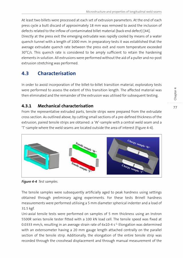
77
Microstructure and properties of longitudinal weld seams
Ch
apte
r 4
At least two billets were processed at each set of extrusion parameters. At the end of each
press cycle a butt discard of approximately 18 mm was removed to avoid the inclusion of
defects related to the inflow of contaminated billet material (back-end defect) [44].
Directly at the press exit the emerging extrudate was rapidly cooled by means of a water
quench tunnel with a length of 1000 mm. In preparatory tests it was established that the
average extrudate quench rate between the press exit and room temperature exceeded
30°C/s. This quench rate is considered to be amply sufficient to retain the hardening
elements in solution. All extrusions were performed without the aid of a puller and no-post
extrusion stretching was performed.
4.3 Characterisation
In order to avoid incorporation of the billet-to-billet transition material, exploratory tests
were performed to assess the extent of this transition length. The affected material was
then eliminated and the remainder of the extrusion was utilised for subsequent testing.
4.3.1 Mechanical characterisationFrom the representative extruded parts, tensile strips were prepared from the extrudate
cross section. As outlined above, by cutting small sections of a pre-defined thickness of the
extrusion, paired tensile strips are obtained: a ‘W’-sample with a central weld seam and a
‘T’-sample where the weld seams are located outside the area of interest (Figure 4-4).
Figure 4-4 Test samples.
The tensile samples were subsequently artificially aged to peak hardness using settings
obtained through preliminary aging experiments. For these tests Brinell hardness
measurements were performed utilising a 5 mm diameter spherical indenter and a load of
31.5 kgf.
Uni-axial tensile tests were performed on samples of 5 mm thickness using an Instron
5500R series tensile tester fitted with a 100 kN load cell. The tensile speed was fixed at
0.0333 mm/s, resulting in an average strain rate of 6x10⁻⁴ s-1. Elongation was determined
with an extensometer having a 20 mm gauge length attached centrally on the parallel
section of the tensile strip. Additionally, the elongation of the entire tensile strip was
recorded through the crosshead displacement and through manual measurement of the
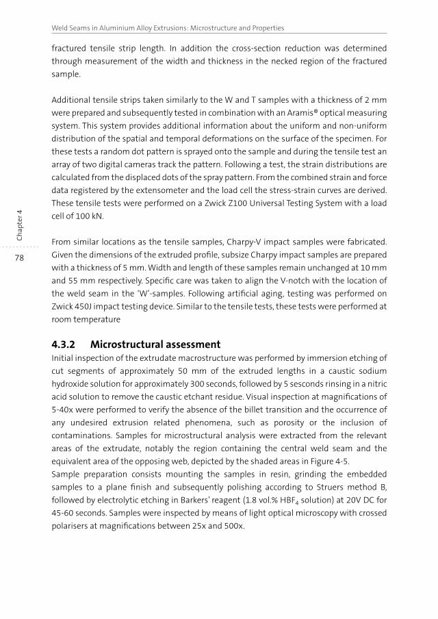
78
Weld Seams in Aluminium Alloy Extrusions: Microstructure and PropertiesC
hap
ter 4
fractured tensile strip length. In addition the cross-section reduction was determined
through measurement of the width and thickness in the necked region of the fractured
sample.
Additional tensile strips taken similarly to the W and T samples with a thickness of 2 mm
were prepared and subsequently tested in combination with an Aramis® optical measuring
system. This system provides additional information about the uniform and non-uniform
distribution of the spatial and temporal deformations on the surface of the specimen. For
these tests a random dot pattern is sprayed onto the sample and during the tensile test an
array of two digital cameras track the pattern. Following a test, the strain distributions are
calculated from the displaced dots of the spray pattern. From the combined strain and force
data registered by the extensometer and the load cell the stress-strain curves are derived.
These tensile tests were performed on a Zwick Z100 Universal Testing System with a load
cell of 100 kN.
From similar locations as the tensile samples, Charpy-V impact samples were fabricated.
Given the dimensions of the extruded profile, subsize Charpy impact samples are prepared
with a thickness of 5 mm. Width and length of these samples remain unchanged at 10 mm
and 55 mm respectively. Specific care was taken to align the V-notch with the location of
the weld seam in the ‘W’-samples. Following artificial aging, testing was performed on
Zwick 450J impact testing device. Similar to the tensile tests, these tests were performed at
room temperature
4.3.2 Microstructural assessmentInitial inspection of the extrudate macrostructure was performed by immersion etching of
cut segments of approximately 50 mm of the extruded lengths in a caustic sodium
hydroxide solution for approximately 300 seconds, followed by 5 sesconds rinsing in a nitric
acid solution to remove the caustic etchant residue. Visual inspection at magnifications of
5-40x were performed to verify the absence of the billet transition and the occurrence of
any undesired extrusion related phenomena, such as porosity or the inclusion of
contaminations. Samples for microstructural analysis were extracted from the relevant
areas of the extrudate, notably the region containing the central weld seam and the
equivalent area of the opposing web, depicted by the shaded areas in Figure 4-5.
Sample preparation consists mounting the samples in resin, grinding the embedded
samples to a plane finish and subsequently polishing according to Struers method B,
followed by electrolytic etching in Barkers’ reagent (1.8 vol.% HBF4 solution) at 20V DC for
45-60 seconds. Samples were inspected by means of light optical microscopy with crossed
polarisers at magnifications between 25x and 500x.
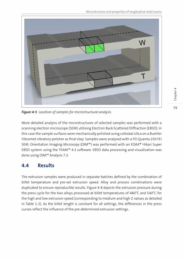
79
Microstructure and properties of longitudinal weld seams
Ch
apte
r 4
Figure 4-5 Location of samples for microstructural analysis.
More detailed analysis of the microstructures of selected samples was performed with a
scanning electron microscope (SEM) utilising Electron Back-Scattered Diffraction (EBSD). In
this case the sample surfaces were mechanically polished using colloidal silica on a Buehler
Vibromet vibratory polisher as final step. Samples were analysed with a FEI Quanta 250 FEI
SEM. Orientation Imaging Microsopy (OIM™) was performed with an EDAX® Hikari Super
EBSD system using the TEAM™ 4.3 software. EBSD data processing and visualisation was
done using OIM™ Analysis 7.3.
4.4 Results
The extrusion samples were produced in separate batches defined by the combination of
billet temperature and pre-set extrusion speed. Alloy and process combinations were
duplicated to ensure reproducible results. Figure 4-8 depicts the extrusion pressure during
the press cycle for the two alloys processed at billet temperatures of 480°C and 540°C for
the high and low extrusion speed (corresponding to medium and high Z-values as detailed
in Table 1-2). As the billet length is constant for all settings, the differences in the press
curves reflect the influence of the pre-determined extrusion settings.
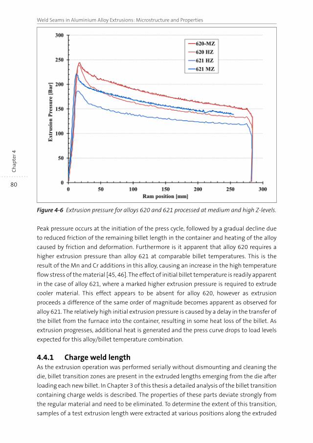
80
Weld Seams in Aluminium Alloy Extrusions: Microstructure and PropertiesC
hap
ter 4
Figure 4-6 Extrusion pressure for alloys 620 and 621 processed at medium and high Z-levels.
Peak pressure occurs at the initiation of the press cycle, followed by a gradual decline due
to reduced friction of the remaining billet length in the container and heating of the alloy
caused by friction and deformation. Furthermore is it apparent that alloy 620 requires a
higher extrusion pressure than alloy 621 at comparable billet temperatures. This is the
result of the Mn and Cr additions in this alloy, causing an increase in the high temperature
flow stress of the material [45, 46]. The effect of initial billet temperature is readily apparent
in the case of alloy 621, where a marked higher extrusion pressure is required to extrude
cooler material. This effect appears to be absent for alloy 620, however as extrusion
proceeds a difference of the same order of magnitude becomes apparent as observed for
alloy 621. The relatively high initial extrusion pressure is caused by a delay in the transfer of
the billet from the furnace into the container, resulting in some heat loss of the billet. As
extrusion progresses, additional heat is generated and the press curve drops to load levels
expected for this alloy/billet temperature combination.
4.4.1 Charge weld lengthAs the extrusion operation was performed serially without dismounting and cleaning the
die, billet transition zones are present in the extruded lengths emerging from the die after
loading each new billet. In Chapter 3 of this thesis a detailed analysis of the billet transition
containing charge welds is described. The properties of these parts deviate strongly from
the regular material and need to be eliminated. To determine the extent of this transition,
samples of a test extrusion length were extracted at various positions along the extruded
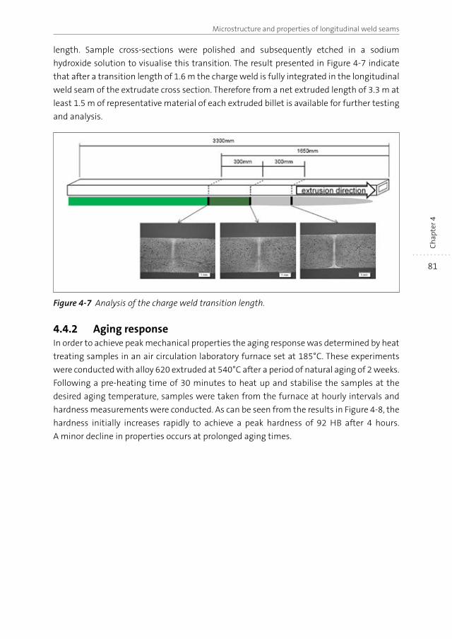
81
Microstructure and properties of longitudinal weld seams
Ch
apte
r 4
length. Sample cross-sections were polished and subsequently etched in a sodium
hydroxide solution to visualise this transition. The result presented in Figure 4-7 indicate
that after a transition length of 1.6 m the charge weld is fully integrated in the longitudinal
weld seam of the extrudate cross section. Therefore from a net extruded length of 3.3 m at
least 1.5 m of representative material of each extruded billet is available for further testing
and analysis.
Figure 4-7 Analysis of the charge weld transition length.
4.4.2 Aging responseIn order to achieve peak mechanical properties the aging response was determined by heat
treating samples in an air circulation laboratory furnace set at 185°C. These experiments
were conducted with alloy 620 extruded at 540°C after a period of natural aging of 2 weeks.
Following a pre-heating time of 30 minutes to heat up and stabilise the samples at the
desired aging temperature, samples were taken from the furnace at hourly intervals and
hardness measurements were conducted. As can be seen from the results in Figure 4-8, the
hardness initially increases rapidly to achieve a peak hardness of 92 HB after 4 hours.
A minor decline in properties occurs at prolonged aging times.
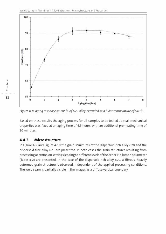
82
Weld Seams in Aluminium Alloy Extrusions: Microstructure and PropertiesC
hap
ter 4
Figure 4-8 Aging response at 185°C of 620 alloy extruded at a billet temperature of 540°C.
Based on these results the aging process for all samples to be tested at peak mechanical
properties was fixed at an aging time of 4.5 hours, with an additional pre-heating time of
30 minutes.
4.4.3 MicrostructureIn Figure 4-9 and Figure 4-10 the grain structures of the dispersoid-rich alloy 620 and the
dispersoid-free alloy 621 are presented. In both cases the grain structures resulting from
processing at extrusion settings leading to different levels of the Zener-Holloman parameter
(Table 4-2) are presented. In the case of the dispersoid-rich alloy 620, a fibrous, heavily
deformed grain structure is observed, independent of the applied processing conditions.
The weld seam is partially visible in the images as a diffuse vertical boundary.
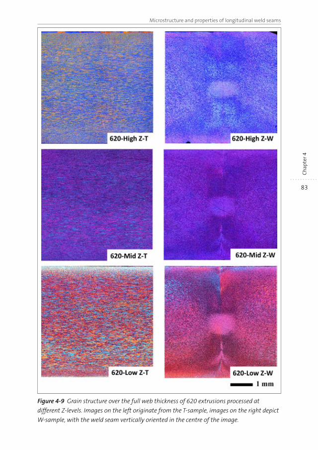
83
Microstructure and properties of longitudinal weld seams
Ch
apte
r 4
Figure 4-9 Grain structure over the full web thickness of 620 extrusions processed at
different Z-levels. Images on the left originate from the T-sample, images on the right depict
W-sample, with the weld seam vertically oriented in the centre of the image.
84
Weld Seams in Aluminium Alloy Extrusions: Microstructure and PropertiesC
hap
ter 4
The appearance of the weld seam changes throughout the width of the web. At the surface
sections of the web the weld seam is not clearly visible and merges with the flow pattern
formed by the remnants of the charge weld contour. Just below the extrusion edges, the
weld seam forms a visibly sharp delineation, marking the location of the weld seam. In the
centre of the extrusion web the weld seam merges with an approximately circular central
region having an apparently indistinct grain morphology. This central area is found to be a
typical feature in all microstructures with a fibrous microstructure.
The grain structure of the dispersoid-free 621 alloy exhibits a strong dependence on the
processing parameters and associated local conditions inside the die. High levels of Z lead
to a fully recrystallised, equiaxed grain structure with relatively minor variations in grain
size. At low Z-values recrystallisation is absent, except for some minor areas adjoining the
inner and outer edges of the extrusion cross section and in the centre of the ‘T’-sample. At
medium Z-values a very diverse microstructure is formed with coarsely recrystallised areas
surrounded by pockets of heavily deformed, fibrous grains. In samples where only partial
recrystallisation has occurred, a coarser grain size has evolved in comparison to samples
with a fully recrystallised grain structure. The non-recrystallised areas in this material
closely resemble the grain structure of the 620 alloy. The weld seam is again visible as a
vertical delineation, losing definition in the centre and at the edges of the extrusion cross
section. In the fully recrystallised structures the weld seam is partially present as a fairly
sharp delineation. In the peripheral parts of the profile the newly formed grains overlap the
weld seam, whilst in the central region the grains predominantly border on the weld seam,
i.e. the grain boundaries from an integral part of the weld seam.
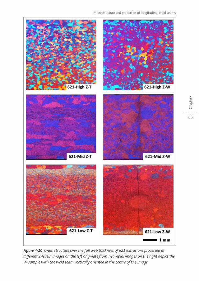
85
Microstructure and properties of longitudinal weld seams
Ch
apte
r 4
Figure 4-10 Grain structure over the full web thickness of 621 extrusions processed at
different Z-levels. Images on the left originate from T-sample; images on the right depict the
W-sample with the weld seam vertically oriented in the centre of the image.
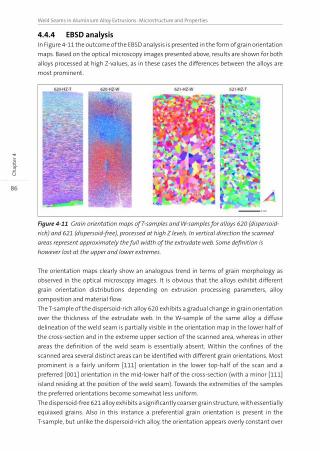
86
Weld Seams in Aluminium Alloy Extrusions: Microstructure and PropertiesC
hap
ter 4
4.4.4 EBSD analysisIn Figure 4-11 the outcome of the EBSD analysis is presented in the form of grain orientation
maps. Based on the optical microscopy images presented above, results are shown for both
alloys processed at high Z-values, as in these cases the differences between the alloys are
most prominent.
Figure 4-11 Grain orientation maps of T-samples and W-samples for alloys 620 (dispersoid-
rich) and 621 (dispersoid-free), processed at high Z levels. In vertical direction the scanned
areas represent approximately the full width of the extrudate web. Some definition is
however lost at the upper and lower extremes.
The orientation maps clearly show an analogous trend in terms of grain morphology as
observed in the optical microscopy images. It is obvious that the alloys exhibit different
grain orientation distributions depending on extrusion processing parameters, alloy
composition and material flow.
The T-sample of the dispersoid-rich alloy 620 exhibits a gradual change in grain orientation
over the thickness of the extrudate web. In the W-sample of the same alloy a diffuse
delineation of the weld seam is partially visible in the orientation map in the lower half of
the cross-section and in the extreme upper section of the scanned area, whereas in other
areas the definition of the weld seam is essentially absent. Within the confines of the
scanned area several distinct areas can be identified with different grain orientations. Most
prominent is a fairly uniform [111] orientation in the lower top-half of the scan and a
preferred [001] orientation in the mid-lower half of the cross-section (with a minor [111]
island residing at the position of the weld seam). Towards the extremities of the samples
the preferred orientations become somewhat less uniform.
The dispersoid-free 621 alloy exhibits a significantly coarser grain structure, with essentially
equiaxed grains. Also in this instance a preferential grain orientation is present in the
T-sample, but unlike the dispersoid-rich alloy, the orientation appears overly constant over
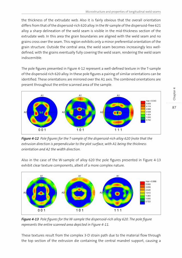
87
Microstructure and properties of longitudinal weld seams
Ch
apte
r 4
the thickness of the extrudate web. Also it is fairly obvious that the overall orientation
differs from that of the dispersoid-rich 620 alloy. In the W-sample of the dispersoid-free 621
alloy a sharp delineation of the weld seam is visible in the mid-thickness section of the
extrudate web. In this area the grain boundaries are aligned with the weld seam and no
grains cross over the seam. This region exhibits only a minor preferential orientation of the
grain structure. Outside the central area, the weld seam becomes increasingly less well-
defined, with the grains eventually fully covering the weld seam, rendering the weld seam
indiscernible.
The pole figures presented in Figure 4-12 represent a well-defined texture in the T-sample
of the dispersoid rich 620 alloy. In these pole figures a pairing of similar orientations can be
identified. These orientations are mirrored over the A1 axis. The combined orientations are
present throughout the entire scanned area of the sample.
Figure 4-12 Pole figures for the T-sample of the dispersoid-rich alloy 620 (note that the
extrusion direction is perpendicular to the plot surface, with A1 being the thickness
orientation and A2 the width direction.
Also in the case of the W-sample of alloy 620 the pole figures presented in Figure 4-13
exhibit clear texture components, albeit of a more complex nature.
Figure 4-13 Pole figures for the W-sample the dispersoid-rich alloy 620. The pole figure
represents the entire scanned area depicted in Figure 4-11.
These textures result from the complex 3-D strain path due to the material flow through
the top section of the extrusion die containing the central mandrel support, causing a
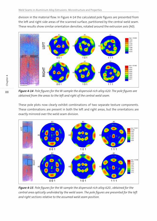
88
Weld Seams in Aluminium Alloy Extrusions: Microstructure and PropertiesC
hap
ter 4
division in the material flow. In Figure 4-14 the calculated pole figures are presented from
the left and right side areas of the scanned surface, partitioned by the central weld seam.
These results show similar orientation densities, rotated around the extrusion axis (A0).
Figure 4-14 Pole figures for the W-sample the dispersoid-rich alloy 620. The pole figures are
obtained from the areas to the left and right of the central weld seam.
These pole plots now clearly exhibit combinations of two separate texture components.
These combinations are present in both the left and right areas, but the orientations are
exactly mirrored over the weld seam division.
Figure 4-15 Pole figures for the W-sample the dispersoid-rich alloy 620., obtained for the
central area optically undivided by the weld seam. The pole figures are presented for the left
and right sections relative to the assumed weld seam position.
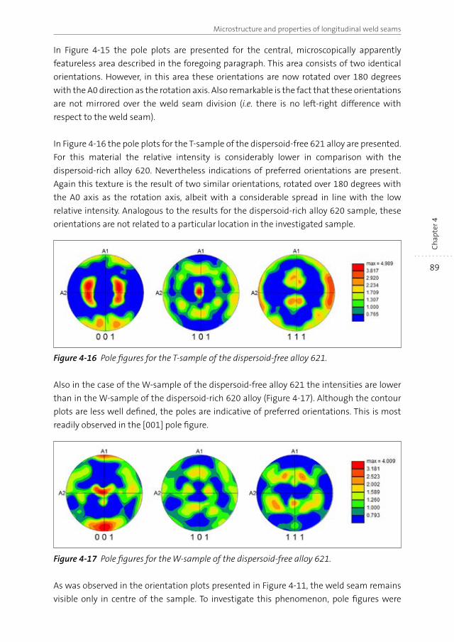
89
Microstructure and properties of longitudinal weld seams
Ch
apte
r 4
In Figure 4-15 the pole plots are presented for the central, microscopically apparently
featureless area described in the foregoing paragraph. This area consists of two identical
orientations. However, in this area these orientations are now rotated over 180 degrees
with the A0 direction as the rotation axis. Also remarkable is the fact that these orientations
are not mirrored over the weld seam division (i.e. there is no left-right difference with
respect to the weld seam).
In Figure 4-16 the pole plots for the T-sample of the dispersoid-free 621 alloy are presented.
For this material the relative intensity is considerably lower in comparison with the
dispersoid-rich alloy 620. Nevertheless indications of preferred orientations are present.
Again this texture is the result of two similar orientations, rotated over 180 degrees with
the A0 axis as the rotation axis, albeit with a considerable spread in line with the low
relative intensity. Analogous to the results for the dispersoid-rich alloy 620 sample, these
orientations are not related to a particular location in the investigated sample.
Figure 4-16 Pole figures for the T-sample of the dispersoid-free alloy 621.
Also in the case of the W-sample of the dispersoid-free alloy 621 the intensities are lower
than in the W-sample of the dispersoid-rich 620 alloy (Figure 4-17). Although the contour
plots are less well defined, the poles are indicative of preferred orientations. This is most
readily observed in the [001] pole figure.
Figure 4-17 Pole figures for the W-sample of the dispersoid-free alloy 621.
As was observed in the orientation plots presented in Figure 4-11, the weld seam remains
visible only in centre of the sample. To investigate this phenomenon, pole figures were
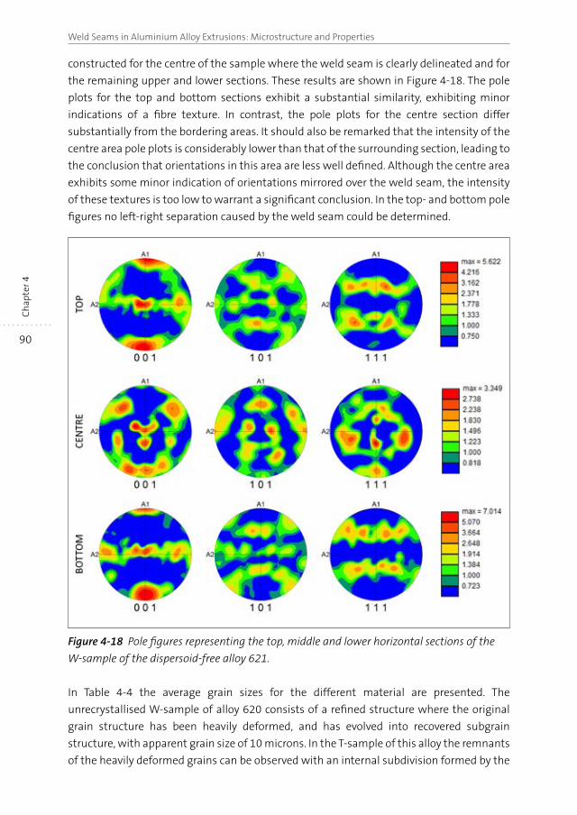
90
Weld Seams in Aluminium Alloy Extrusions: Microstructure and PropertiesC
hap
ter 4
constructed for the centre of the sample where the weld seam is clearly delineated and for
the remaining upper and lower sections. These results are shown in Figure 4-18. The pole
plots for the top and bottom sections exhibit a substantial similarity, exhibiting minor
indications of a fibre texture. In contrast, the pole plots for the centre section differ
substantially from the bordering areas. It should also be remarked that the intensity of the
centre area pole plots is considerably lower than that of the surrounding section, leading to
the conclusion that orientations in this area are less well defined. Although the centre area
exhibits some minor indication of orientations mirrored over the weld seam, the intensity
of these textures is too low to warrant a significant conclusion. In the top- and bottom pole
figures no left-right separation caused by the weld seam could be determined.
Figure 4-18 Pole figures representing the top, middle and lower horizontal sections of the
W-sample of the dispersoid-free alloy 621.
In Table 4-4 the average grain sizes for the different material are presented. The
unrecrystallised W-sample of alloy 620 consists of a refined structure where the original
grain structure has been heavily deformed, and has evolved into recovered subgrain
structure, with apparent grain size of 10 microns. In the T-sample of this alloy the remnants
of the heavily deformed grains can be observed with an internal subdivision formed by the
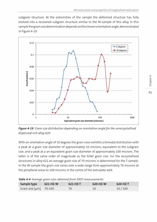
91
Microstructure and properties of longitudinal weld seams
Ch
apte
r 4
subgrain structure. At the extremities of the sample the deformed structure has fully
evolved into a recovered subgrain structure similar to the W-sample of this alloy. In this
sample the grain size determination depends on the chosen orientation angle, demonstrated
in Figure 4-19.
Figure 4-19 Grain size distribution depending on orientation angle for the unrecrystallised
dispersoid-rich alloy 620.
With an orientation angle of 10 degrees the grain sizes exhibits a bimodal distribution with
a peak at a grain size diameter of approximately 10 microns, equivalent to the subgrain
size, and a peak at a an equivalent grain size diameter of approximately 100 microns. The
latter is of the same order of magnitude as the billet grain size. For the recrystallised
structures in alloy 621 an average grain size of 70 microns is determined for the T-sample.
In the W-sample the grain size varies over a wide range from approximately 70 microns at
the peripheral areas to 100 microns in the centre of the extrudate web.
Table 4-4 Average grain sizes obtained from EBSD measurements
Sample type 621-HZ-W 621-HZ-T 620-HZ-W 620-HZ-T
Grain size [μm] 70-100 70 10 10 / 100
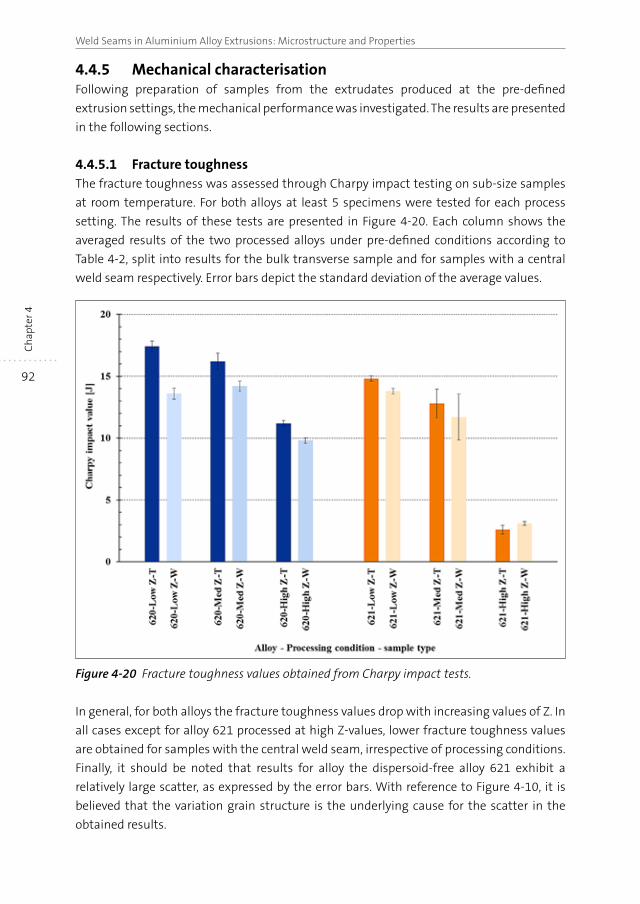
92
Weld Seams in Aluminium Alloy Extrusions: Microstructure and PropertiesC
hap
ter 4
4.4.5 Mechanical characterisationFollowing preparation of samples from the extrudates produced at the pre-defined
extrusion settings, the mechanical performance was investigated. The results are presented
in the following sections.
4.4.5.1 Fracture toughnessThe fracture toughness was assessed through Charpy impact testing on sub-size samples
at room temperature. For both alloys at least 5 specimens were tested for each process
setting. The results of these tests are presented in Figure 4-20. Each column shows the
averaged results of the two processed alloys under pre-defined conditions according to
Table 4-2, split into results for the bulk transverse sample and for samples with a central
weld seam respectively. Error bars depict the standard deviation of the average values.
Figure 4-20 Fracture toughness values obtained from Charpy impact tests.
In general, for both alloys the fracture toughness values drop with increasing values of Z. In
all cases except for alloy 621 processed at high Z-values, lower fracture toughness values
are obtained for samples with the central weld seam, irrespective of processing conditions.
Finally, it should be noted that results for alloy the dispersoid-free alloy 621 exhibit a
relatively large scatter, as expressed by the error bars. With reference to Figure 4-10, it is
believed that the variation grain structure is the underlying cause for the scatter in the
obtained results.
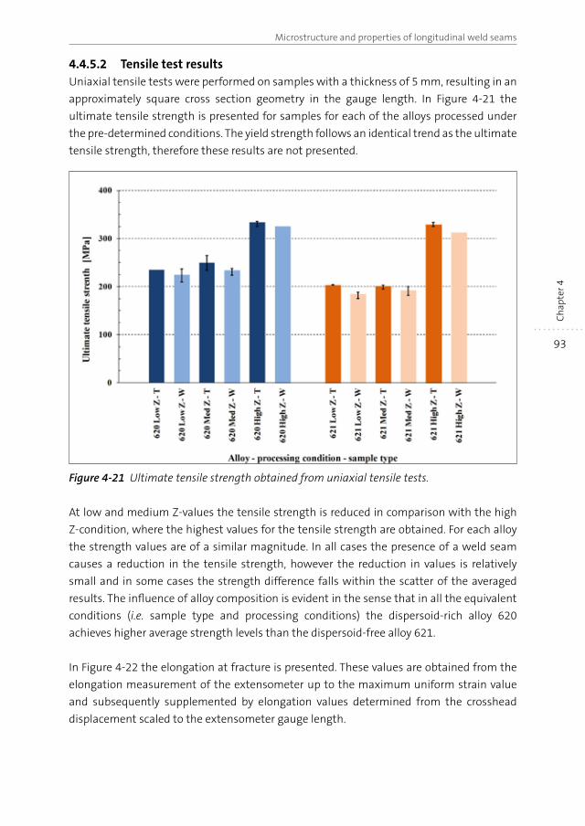
93
Microstructure and properties of longitudinal weld seams
Ch
apte
r 4
4.4.5.2 Tensile test resultsUniaxial tensile tests were performed on samples with a thickness of 5 mm, resulting in an
approximately square cross section geometry in the gauge length. In Figure 4-21 the
ultimate tensile strength is presented for samples for each of the alloys processed under
the pre-determined conditions. The yield strength follows an identical trend as the ultimate
tensile strength, therefore these results are not presented.
Figure 4-21 Ultimate tensile strength obtained from uniaxial tensile tests.
At low and medium Z-values the tensile strength is reduced in comparison with the high
Z-condition, where the highest values for the tensile strength are obtained. For each alloy
the strength values are of a similar magnitude. In all cases the presence of a weld seam
causes a reduction in the tensile strength, however the reduction in values is relatively
small and in some cases the strength difference falls within the scatter of the averaged
results. The influence of alloy composition is evident in the sense that in all the equivalent
conditions (i.e. sample type and processing conditions) the dispersoid-rich alloy 620
achieves higher average strength levels than the dispersoid-free alloy 621.
In Figure 4-22 the elongation at fracture is presented. These values are obtained from the
elongation measurement of the extensometer up to the maximum uniform strain value
and subsequently supplemented by elongation values determined from the crosshead
displacement scaled to the extensometer gauge length.
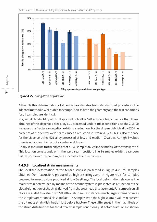
94
Weld Seams in Aluminium Alloy Extrusions: Microstructure and PropertiesC
hap
ter 4
Figure 4-22 Elongation at fracture.
Although this determination of strain values deviates from standardised procedures, the
adopted method is well suited for comparison as both the geometry and the test conditions
for all samples are identical.
In general the ductility of the dispersoid-rich alloy 620 achieves higher values than those
obtained of the dispersoid-free alloy 621 processed under similar conditions. As the Z-value
increases the fracture elongation exhibits a reduction. For the dispersoid-rich alloy 620 the
presence of the central weld seam causes a reduction in strain values. This is also the case
for the dispersoid-free 621 alloy processed at low and medium Z-values. At high Z-values
there is no apparent effect of a central weld seam.
Finally, it should be further noted that all W-samples failed in the middle of the tensile strip.
This location corresponds with the weld seam position. The T-samples exhibit a random
failure position corresponding to a stochastic fracture process.
4.4.5.3 Localised strain measurementsThe localised deformation of the tensile strips is presented in Figure 4-23 for samples
obtained from extrusions produced at high Z-settings and in Figure 4-24 for samples
prepared from extrusions produced at low Z-settings. The local deformation, shown as the
major strain determined by means of the Aramis system is presented as a function of the
global elongation of the strip, derived from the crosshead displacement. For comparison all
plots are scaled to a strain of 15% although in some instances much larger strains occur as
the samples are strained close to fracture. Samples with the highest strain values represent
the ultimate strain distribution just before fracture. These differences in the magnitude of
the strain distributions for the different sample conditions just before fracture are shown
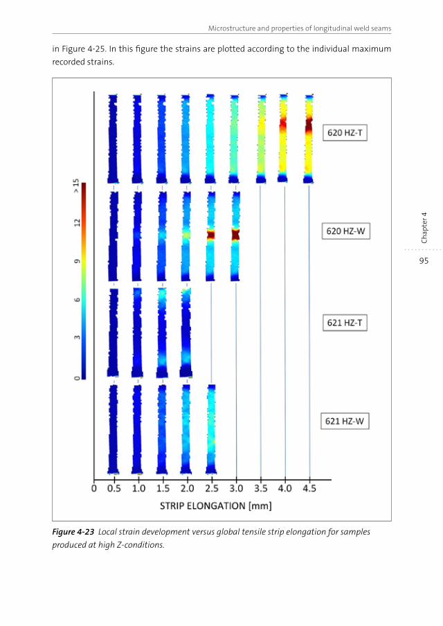
95
Microstructure and properties of longitudinal weld seams
Ch
apte
r 4
in Figure 4-25. In this figure the strains are plotted according to the individual maximum
recorded strains.
Figure 4-23 Local strain development versus global tensile strip elongation for samples
produced at high Z-conditions.
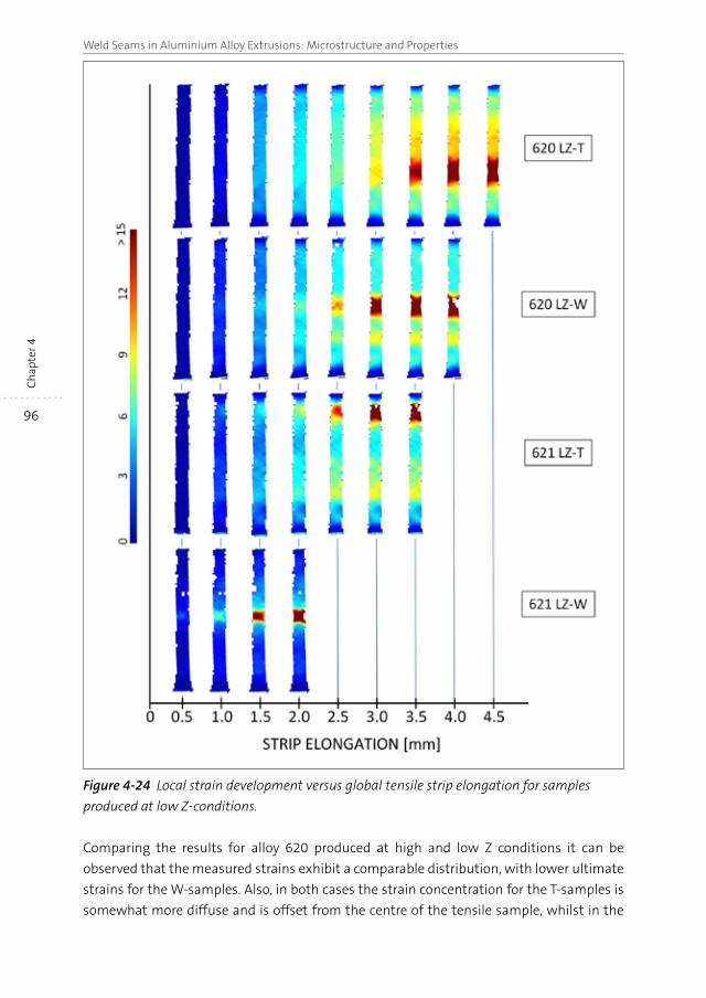
96
Weld Seams in Aluminium Alloy Extrusions: Microstructure and PropertiesC
hap
ter 4
Figure 4-24 Local strain development versus global tensile strip elongation for samples
produced at low Z-conditions.
Comparing the results for alloy 620 produced at high and low Z conditions it can be
observed that the measured strains exhibit a comparable distribution, with lower ultimate
strains for the W-samples. Also, in both cases the strain concentration for the T-samples is
somewhat more diffuse and is offset from the centre of the tensile sample, whilst in the
97
Microstructure and properties of longitudinal weld seams
Ch
apte
r 4
W-sample strain is closely concentrated in the middle of the tensile strip, i.e. at the location
of the weld seam.
For alloy 621 it can be readily observed that markedly different strain distributions are
obtained, depending on the processing conditions. Samples produced at high Z-values
exhibit diffuse strain distributions, with the W-sample having a higher ultimate strain than
the T-sample. At low Z-conditions deformation is concentrated around the fracture location.
In the T-sample the strain is again offset from the centre of the tensile strip, whilst in the
W-sample strain is closely concentrated around the weld seam location. At low Z-conditions
significantly lower ultimate strains are obtained for the W-sample.
Comparing the two alloys processed under similar processing conditions, it is obvious that
at high Z-conditions the two alloys exhibit very different strain distributions along the
gauge length (Figure 4-23). Strains rapidly concentrate in the 620 alloy, whilst in the 621
alloy the strain is more widespread. In alloy 620 a lower ultimate strain occurs in the
W-sample, whilst in alloy 621 the T-sample exhibits a somewhat higher ultimate strain. It
should also be noted that alloy 620 exhibits higher strains, independent of the sample type.
This is also the case for the alloy processed at low Z conditions (Figure 4-24). In both cases
the W-samples have a lower ultimate strain than the T-samples, the difference being more
pronounced in alloy 621. In contrast to alloy 621 processed at low Z-conditions, the high
Z-condition variation now also exhibits a localised strain distribution, similar to alloy 620.
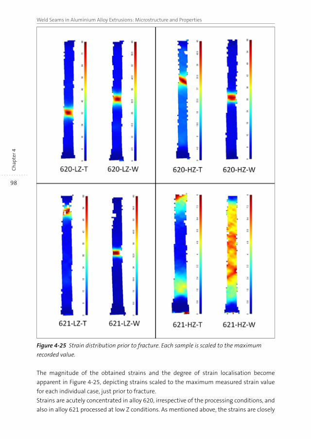
98
Weld Seams in Aluminium Alloy Extrusions: Microstructure and PropertiesC
hap
ter 4
Figure 4-25 Strain distribution prior to fracture. Each sample is scaled to the maximum
recorded value.
The magnitude of the obtained strains and the degree of strain localisation become
apparent in Figure 4-25, depicting strains scaled to the maximum measured strain value
for each individual case, just prior to fracture.
Strains are acutely concentrated in alloy 620, irrespective of the processing conditions, and
also in alloy 621 processed at low Z conditions. As mentioned above, the strains are closely
99
Microstructure and properties of longitudinal weld seams
Ch
apte
r 4
concentrated in the area of the weld seam in the centre of the W-samples, whereas the
strain concentrations in the T-samples are more randomly positioned. The more diffuse
strain distributions in the T- and W-samples of alloy 621 processed at low Z conditions are
coupled with significantly lower strain magnitudes, being approximately a factor of 5-10
times lower than maximum strain values obtained for the other alloy/processing
combinations. Particularly noticeable is the widespread strain distribution in the W-sample.
4.5 Discussion
The results in the previous section clearly demonstrate the combined effects of alloy
composition and extrusion processing parameters on the properties of the longitudinal
weld seams. The addition of the dispersoid-forming elements Cr and Mn in alloy 620 results
in suppression of recrystallisation, irrespective of the chosen processing conditions. The
original equiaxed grain structure of the billet material is thereby transformed into a fibrous
microstructure oriented along the flow path of the material. Inside the deformed grains a
recovered subgrain structure is formed.
The absence of the dispersoid forming elements in alloy 621 leads a wide range of grain
structures, strongly depending on the processing conditions. At high Z-levels, full
recrystallisation of the alloy occurs, resulting in an equiaxed microstructure. At low Z-levels
recrystallisation is largely suppressed, with exception of the area immediately bordering
the edge of the extrusion cross section, where a band of larger grains are formed (i.e.
peripheral coarse grain formation). Additionally, at the mid-centre location of the T-sample
a narrow band of recrystallised grains has formed. At medium Z-levels a composite grain
structure forms in the dispersoid-free alloy 621, with pockets of recrystallised grains
surrounded by areas of heavily deformed, unrecrystallised grains, similar to the structure
observed by Poletti et al. in hot extruded AA6082 alloy [47].
A secondary effect of the variation in processing conditions concerns the thermal influence
on the solutionising of the strengthening elements Si and Mg. At low and medium Z-values
the operative temperature levels during extrusion are insufficient to achieve a fully
solutionised alloy condition and a subsequent supersaturated condition following
quenching of the materials. As a result lower strength properties of the materials are
obtained after artificial aging, whilst the tensile ductility and the fracture toughness of the
material in this condition exceed the levels of the fully solutionised, peak aged samples.
This phenomenon occurs equally for both alloys and for all of the material extruded from
the entire extruded billet at similar process settings. Therefore the comparison of properties
of material with and without a weld seam within each set of fixed process conditions
remains possible.
In the case of unrecrystallised microstructures the weld seam is visible as a result of the
material flow pattern in the die. A linear demarcation is present at the location where the
material recombines after having been separated by the mandrel supports. In the mid-
section of the extrusion cross section this border is less well defined; instead a roughly
100
Weld Seams in Aluminium Alloy Extrusions: Microstructure and PropertiesC
hap
ter 4
circular area with an apparently indistinct grain structure is observed by optical microscopy.
These microstructures correlate with results obtained in an extruded rectangular bar with
a central weld seam resulting from a central obstruction inside the die channel [48]. In
these experiments an ‘unstructured’ region was present in the region of the weld seam.
Upon closer inspection this area comprises small grains not observable with light optical
microscopy. In the recrystallised grain structures the weld seam position coincides with a
linear arrangement of grain boundaries in the central part of the extrudate web. Closer to
the extrusion edges the grain boundaries assume a more random pattern and the definition
of the weld seam position becomes unclear.
The occurrence of this central area with a different microstructure in comparison with the
surrounding area is a direct result of the local thermomechanical conditions inside the
extrusion tooling, in combination with the specific alloy response controlled by the
dispersoid content. Microstructural evolution is controlled by the driving force and hence
stored energy of the system. During extrusion dynamic recrystallisation occurs, refining the
grain structure as long as recrystallisation nuclei form and the operative driving force is
present. With a relatively lower driving force in the centre of the sample, dynamic
recrystallisation will stop earlier than at areas further removed from the central area. In the
dispersoid-rich material dynamic recovery however still operates and the subgrain structure
inside the deformed original grains evolves into a fully recovered structure.
In dispersoid-free material static recrystallisation occurs when material exits the extrusion
tooling, and continues up to the point that the alloy is quenched and further structural
reorganisation in prevented. The lower driving force related to the reduced shear
deformation at the centre area, in combination with a higher retained heat content in the
centre of the extrudate web facilitates an earlier onset and longer duration of static
recrystallisation, resulting in a coarser recrystallised grain structure.
Detailed analysis of the EBSD measurements reveals that in the case of the unrecrystallised
samples deformation textures are formed consisting of combinations of at least two
discrete preferred orientations. In the T-sample the resultant texture originates from plane
strain deformation conditions, operating largely in the centre area of the extrusion web,
whilst close to the edges of the extrudate the deformation changes to a shear dominated
mode [40]. This phenomenon is directly related to the die geometry, where the formation
of the T-section is essentially analogous to the extrusion of a flat strip and in a broader
sense can also be compared to hot rolling operations. Similar conditions are reported by
Poole et al. in experiments where billets are extruded into a rectangular profile under
conditions where recrystallisation is suppressed [43]. In the T-sample the crystallographic
structure consists of two paired texture components which are mirrored over the A1-axis
(i.e. the thickness direction). These orientations are not concentrated in specific areas of the
cross-section but exhibit a fairly random widespread distribution in the investigated
sample area.
101
Microstructure and properties of longitudinal weld seams
Ch
apte
r 4
Distinct crystallographic textures are also present in the W-sample of the unrecrystallised
material, albeit of a different nature in comparison with the T-sample. This is related to the
difference in material flow, where in the case of the W-sample a more complex 3-D flow
operates, as the aluminium in the die not only flows in the X-direction (i.e. along the
extrusion axis) towards the die exit but also in Y-direction (i.e. in a lateral direction as the
material recombines downstream of the mandrel supports) and in the Z direction as the
material flows in a radial direction from the peripheral areas in the extrusion die towards
the central area in the die where the extrudate is formed. Due to these complex localised
flow patterns a group of crystallographic orientations evolve, as shown in Figure 4-13. The
nature of these orientations becomes clearer when separate areas of the sample are
analysed. Focussing on the areas divided by the weld seam in the lower half of the sample,
a combination of two distinct orientations consisting of the [001] and [111] poles aligned
in the extrusion direction is revealed and plotted in Figure 4-14. These orientations are
present on either side of the weld seam, however with a mirrored symmetry relative to the
weld seam division. Performing a similar analysis of the left and right areas of the,
microstructurally ‘unstructured’ circular area located approximately in the centre of the
sample, again a combination of two preferred crystallographic orientations are obtained. In
stark contrast to the findings for the lower half of the sample as discussed above, these
orientations are unaffected by the weld seam division. Hence the texture components in
this area can be considered as being continuous, despite the presence of a weld seam
division. It is however evident that at least a partial texture discontinuity is present, divided
by the weld seam. These textures again compare well with findings of Claves [48] and
Geertruyden [41] in extruded alloy AA6061 rectangular bars with a central weld seam.
Despite some minor differences related to local variations in grain morphology due to the
different alloys used in these studies, similar crystallographic arrangements were observed
for the weld seam area. It should however be noted that in the study described above the
separate areas divided by the weld seam were not analysed and the results therefore only
show the combined arrangement over the full width of the weld seam. Nevertheless from
these presented results it is evident that a texture boundary is present across the weld
seam.
In the dispersoid-free material processed at mid- and high Z conditions the deformed
fibrous grain structure caused by the extrusion deformation has been completely replaced
by a fully recrystallised grain structure. Likewise, the pronounced deformation textures
described above have been essentially eliminated. Instead, much weaker and less well-
defined orientation distributions have evolved. Similar to the T-sample of the dispersoid-
rich 620 alloy, a composite texture is present in the recrystallised 621 alloy, devoid of
dispersoids. Recrystallisation has however led to a considerably lower intensity of these
orientations, due to the more random evolution of the newly formed grains. It is believed
that the evolved crystallographic texture is partially related to the deformed material state
undergoing dynamic recrystallised during extrusion.
102
Weld Seams in Aluminium Alloy Extrusions: Microstructure and PropertiesC
hap
ter 4
The recrystallised W-sample of the dispersoid-free 621 alloy reveals different crystallographic
orientations depending on the evaluated area, with similar lower intensities and larger
spreads in the orientations as observed for the T-sample. Indications of a [111] fibre
orientation are obtained for both the top section and bottom area of the sample. This
texture is similar to the orientation found in the surface layer of rolled sheet, where the
shear texture has been replaced by a fibre texture following recrystallisation, as discussed
by Engler et al. [49]. As reported the orientations in the investigated sample were found to
be continuous across the sample width, i.e. there was no influence related to the weld seam
position. This is a clear indication that the recrystallisation process has eliminated the
effects of material flow as the metal streams recombine. The central area of this sample
exhibits a distinctly different texture. It is believed that the conditions at this locations
(lower shear, temperature, lower driving force) results in a partial transformation of the
change of the crystallographic texture remaining from deformation, however not to the
same extent as at other locations. Hence a complex, intermingled combination of texture
components is formed. In this area a minimal influence of the weld seam may have
remained, however in the light of the very weak crystallographic arrangement it may well
be assumed that no discernible impact on mechanical properties remains. Differences in
the mechanical properties between these materials with and without a weld seam (if any)
are therefore attributed to the morphological features of the recrystallised grain structure.
The microstructures for the different alloys and processing conditions presented above are
a direct explanation for the differences in mechanical properties. The non-recrystallised
materials exhibit a local, discontinuous microstructure at the weld seam location, in
combination with a pronounced deformation texture, with crystallographic orientations
mirrored across the weld seam. Upon mechanical straining the weld seam will deform
preferentially at this region, resulting in a strain localisation in the near vicinity of the weld
seam. Ultimately failure occurs at lower deformation values in comparison with the
T-samples.
In recrystallised materials the fibrous microstructure resulting from the deformation
during extrusion is eliminated, leaving a uniform relatively coarse grained equiaxed grain
structure. Moreover, the pronounced crystallographic orientations are replaced by far
weaker, less well-defined orientations. Only in the central area of the sample some minor
remnants of the mirrored crystallographic arrangement are preserved. Notwithstanding
these partial remains of the weld seam, visible in the form as grain boundaries aligned
along the weld seam location, strain distribution occurs more widespread through the
material. In this material failure occurs in in a brittle manner through grain boundary
decohesion [50]. In the recrystallised random grain structure failure will thus occur at those
grain boundaries which are adversely oriented with respect to the maximum resolved
stress, regardless of the position relative to the (prior) weld seam.
103
Microstructure and properties of longitudinal weld seams
Ch
apte
r 4
4.6 Conclusions
The properties of longitudinal weld seams of two AA6082-type alloys were investigated
through detailed characterisation of samples obtained from a specifically designed
extrudate. Significantly different microstructures were produced by varying the alloy
composition and the extrusion processing parameters.
In non-recrystallised alloys a fibrous grain structure forms. This structure exhibits a
discontinuity when a weld seam is formed by the material flow inside the tooling, in
combination with a complex pronounced crystallographic deformation texture. These
orientations are mirrored with respect to the weld seam delineation. These discontinuous
grain structures with associated mirrored crystallographic orientations result in strain
localisation when the material is plastically deformed up to the point of failure. In the
absence of a weld seam, strain remains more evenly distributed throughout the continuous
grain structure and failure occurs at a higher degree of deformation. Hence in non-
recrystallised, fibrous grain structures the tensile ductility and fracture toughness are
adversely affected by the presence of a weld seam. The discontinuous microstructure
caused by a weld seam does not influence the strength properties (i.e. yield strength and
ultimate tensile strength) in a significant manner.
In recrystallised grain structures the original crystallographic deformation texture
components are largely eliminated. In addition the recrystallised grains exhibit only a
partial discontinuity at the weld seam. As the grain structure in combination with the
much weaker newly formed textures hardly bear any relation with the weld seam, strain
accommodation occurs more diffuse throughout the material, regardless of the presence
of a weld seam. Thus in recrystallised alloys the strength properties, fracture toughness
and the ductility are independent of the presence of a weld seam.
This research therefore demonstrates that the presence of a weld seam in non-recrystallised
material impacts the strain distribution and associated ductility due to the presence of a
discontinuous crystallographic deformation texture. In material with a continuous
crystallographic texture and also in the absence of texture components, strain is more
homogeneously distributed and ductility is not affected.
104
Weld Seams in Aluminium Alloy Extrusions: Microstructure and PropertiesC
hap
ter 4
4.7 References
[1] R.F. Tylecote, The solid phase welding of metals, 1st ed., Edward Arnold Ltd, London, 1968.
[2] R. Akeret, Journal of the Institute of Metals, 100 (1972), pp. 202-208.
[3] B. Bourqui, A. Huber, C. Moulin, A. Brunetti, Y. Krähenbuhl, The first International Congress
of the Extruders’ Division of the European Aluminium Association, EAA, Brescia, It., 2002.
[4] L. Donati, L. Tomesani, J. Mater. Process. Tech., 153-154 (2004), pp. 366-373.
[5] L. Donati, L. Tomesani, Mater. Sci. Forum., 604-605 (2009), pp. 121-131.
[6] I. Duplancic, J. Prgin, Sixth International Aluminum Extrusion Technology Seminar,
Aluminum Association, Chicago, IL, USA, 1996, pp. 225-230.
[7] M. Plata, J. Piwnik, Seventh International Aluminum Extrusion Technology Seminar, The
Aluminum Association, Chicago, IL, USA, 2000, pp. 205-211.
[8] I. Alfaro, F. Gagliardi, J. Olivera, E. Cueto, L. Filice, F. Chinesta, Esaform 2009, Springer,
University of Twente, The Netherlands, 2009.
[9] S. Bozzi, M. Vedani, D. Lotti, G. Passoni, Metallurgical Science and Technology, 27 (2009),
pp. 20-29.
[10] E. Ceretti, L. Mazzoni, C. Giardini, AIP Conference Proceedings, 908 (2007), pp. 419-424.
[11] E. Ceretti, L. Mazzoni, C. Giardini, Esaform 2009, Springer, University of Twente, The
Netherlands, 2009.
[12] L. Donati, L. Tomesani, in: D. Banabic (Ed.) The 8th Esaform Conference on Material
Forming, The Romanian Academy Publishing House Bucharest, Cluj-Napoca, Romania,
2005, pp. 561-565.
[13] L. Donati, L. Tomesani, International Conference on Technology of Plasticity, Bariani, P.F.,
Verona, 2005, pp. 227-228.
[14] I. Flitta, T. Sheppard, Mater. Sci. Tech. Ser., 18 (2002), pp. 987-994.
[15] J. Gasiorczyk, J. Richert, Seventh International Aluminum Extrusion Technology Seminar,
The Aluminum Association, Chicago, IL, USA, 2000, pp. 195-202.
[16] H.H. Jo, S.K. Lee, C.S. Jung, B.J. Kim, J. Mater. Process. Tech., 2006 (2006), pp. 223-231.
[17] K.J. Kim, C.H. Lee, D.Y. Yang, J. Mater. Process. Tech., 130-131 (2002), pp. 426-431.
[18] J.M. Lee, B.M. Kim, C.G. Kang, Materials and Design, 2005 (2005), pp. 327-336.
[19] M. Schwane, F. Gagliardi, A. Jäger, N.B. Khalifa, A.E. Tekkaya, Esaform 2013, Trans Tech
Publications, Aveiro, Portugal, 2013, pp. 787-793.
[20] M. Schwane, T. Klopppenborg, A. Reeb, N. Ben Kalifa, A. Brosius, K.A. Weidenmann, A.E.
Tekkaya, in: M. Merklein, H. Hagenah (Eds.) Esaform 2012, Trans Tech Publications Inc.,
Neurenberg, Germany, 2012, pp. 517-522.
[21] T. Welo, A. Smaabrekke, H. Valberg, Aluminium (Germany), 71 (1995), pp. 90-94.
[22] A.R. Bandar, K. Lorcharoensery, W.Z. Misiolek, J. Mater. Process. Tech., 80-81 (1998),
pp. 657-664.
[23] I. Flitta, T. Sheppard, Mater. Sci. Tech. Ser., 21 (2005), pp. 648-654.
[24] Y.A. Khan, H. Valberg, I. Irgens, Int. J. Mater. Form., 2 (2009), pp. 109-112.
[25] Y.T. Kim, K. Ikeda, T. Murakami, J. Mater. Process. Tech. 121, (2002), pp. 107-115.
[26] T. Murakami, Welding International, 13 (1999), pp. 425-429.
105
Microstructure and properties of longitudinal weld seams
Ch
apte
r 4
[27] H. Valberg, Int. J. Mater. Prod. Tec., 17 (2002), pp. 497-556.
[28] H. Valberg, T. Loeken, M. Hval, B. Nyhus, C. Thaulow, Int. J. Mater. Prod. Tec., 10 (1995),
pp. 222-267.
[29] R. Akeret, Fifth Aluminum Extrusion Seminar, The Aluminum Association, Chicago, IL,
USA, 1992, pp. 319-336.
[30] A. Oosterkamp, L.D. Oosterkamp, A. Nordeide, Weld. J., (2004), pp. 255-261.
[31] T. Pettersen, S. Abtahi, J.A. Seater, T. Furu, H.E. Ekström, in: J.F. Nie, A.J. Morton, B.C.
Muddle (Eds.) 9th International Conference on Aluminium Alloys (2004), Institute of
Materials Engineering Australasia Ltd, Brisbane, Australia, 2004, pp. 457-463.
[32] T. Kayser, B. Klusemann, H.G. Lambers, H.J. Maier, B. Svendsen, Materials Science and
Engineering A, 527 (2010), pp. 6568-6573.
[33] M. Schikorra, L. Donati, L. Tomesani, A.E. Tekkaya, Journal of Mechanical Science and
Technology, 21 (2007), pp. 1445-1451.
[34] O. Ryen, B. Holmedal, S. Li, P. Van Houtte, H.J. Roven, E. Nes, Materials Forum, 28 (2004),
pp. 1004-1009.
[35] K.O. Pedersen, O.G. Lademo, T. Berstad, T. Furu, O.S. Hopperstad, J. Mater. Process. Tech.,
200 (2008), pp. 77-93.
[36] M. De Haas, J.T.M. De Hosson, J. Mater. Sci., 37 (2002), pp. 5065-5073.
[37] J.A. Blind, J.W. Martin, Materials Science and Engineering, 57 (1983), pp. 49-54.
[38] J.M. Dowling, J.W. Martin, Acta. Metall. Mater., 24 (1976), pp. 1147-1153.
[39] G. Mrówka-Nowotnik, J. Sieniawski, A. Nowotnik, Journal of Achievements in Materials
and Manufacturing Engineering (JAMME), 17 (2006), pp. 105-108.
[40] H. Bjerkhaas, S.K. Fjeldbo, H.J. Roven, J. Hjelen, R. Chiron, T. Furu, Mater. Sci. Forum., 519-
521 (2006), pp. 809-814.
[41] W.H. Van Geertruyden, S.R. Claves, W.Z. Misiolek, Metall. Mater. Trans. A, 33 (2002),
pp. 693-700.
[42] S. Yasuda, K. Atsuta, S. Wakaguri, K. Ichitani, A. Hibino, in: H. Weiland, A.D. Rollett, W.A.
Cassada (Eds.) 13th International Conference on Aluminum Alloys, TMS (The Minerals,
Metals & Materials Society), Pittsburgh, PA, USA, 2013, pp. 807-812.
[43] W.J. Poole, J. Chen, Y. Mahmoodkhani, M.A. Wells, N. Parson, Eleventh International
Aluminum Extrusion Technology Seminar, ET ‘16, ET Foundation, Chicago. IL, USA, 2016,
pp. 725-734.
[44] V.I. Johannes, C.W. Jowett, R.F. Dickson, Sixth International Aluminum Extrusion
Technology Seminar, Aluminum Association, Chicago, IL, USA, 1996, pp. 89-94.
[45] H.J. McQueen, O.C. Celliers, Canadian Metallurgical Quarterly, 35 (1996), pp. 305-319.
[46] T. Furu, R. Østhus, N. Telioui, R. Aagård, M. Bru, O.R. Myhr, Eleventh International
Aluminum Extrusion Technology Seminar, ET ‘16, ET Foundation, Chicago, IL, USA, 2016,
pp. 567-590.
[47] C. Poletti, M. Rodriguez-Hortalá, M. Hauser, C. Sommitsch, Materials Science and
Engineering A, 528 (2011), pp. 2423-2430.
[48] S.R. Claves, Characterization and analysis of the localized deformation of 6xxx
aluminum alloy extrudates, MSc thesis, Paper 723, Lehigh University, Bethlehem, PA, 2002.
106
Weld Seams in Aluminium Alloy Extrusions: Microstructure and PropertiesC
hap
ter 4
[49] O. Engler, H.C. Kim, M.Y. Huh, Mater. Sci. Tech. Ser., 17 (2001), pp. 75-86.
[50] E. Iesulauro, Decohesion of grain boundaries in three-dimensional statistical
representations of aluminum polycrystals, Doctoral Thesis, Cornell Fracture Group, Cornell
University, Ithaca, NY, USA, 2006
CHAPTER 5
Microstructural and X-ray tomographic analysis of damage in extruded aluminium weld seams 6
Abstract
In this study X-ray computer tomography is used to determine damage evolution in extrusion
weld seams loaded close to failure for two comparable AlSiMg alloys with distinctively
different grain structures. In the dispersoid-free alloy recrystallisation occurs upon extrusion
and the weld seam has no effect on mechanical properties. No preferential void formation in
the weld seam region was detected. In the non-recrystallising dispersoid-rich alloy the weld
seam leads to a reduced ductility. There are no signs of internal void formation and damage
initiation was found to be close to the surface. It is argued that for the non-recrystallising
alloy the effect of the weld seam on the ductility is related to a sharp texture gradient across
the weld seam.
6 Based on the following publication: A.J. Den Bakker, X. Ma, L. Katgerman, S.v.d. Zwaag, Mater. Sci. Tech.
Ser., 31 (2015), pp. 94-104.
108
Weld Seams in Aluminium Alloy Extrusions: Microstructure and PropertiesC
hap
ter 5
5.1 Introduction
In the case of hollow aluminium sections produced through hot extrusion the material
flow through porthole dies leads to so-called weld seams where separated material streams
created by bridges suspending the cores or mandrels recombine through a solid bonding
process.
The specific thermomechanical conditions at the location of the rejoining streams in
porthole dies will have an obvious bearing on the microstructure of the material. Under
unfavourable processing conditions weld seam defects may occur, such as so called ‘kissing
bonds’ [1] and porosity [2], leading to extruded parts with severely impaired mechanical
properties. However, even for ‘perfect’ weld seams the mechanical properties of the weld
seam region, in particular the tensile ductility, when measured in the direction perpendicular
to the extrusion direction are not always identical to those measured on samples not
containing the weld seam [3, 4]. Often the mechanical integrity of extrusion weld seams is
characterised through mechanical loading of samples, such as bending tests and cone
expansion tests. The outcome of these tests is of a qualitative nature, limiting the
information to pass or fail judgements. Quantification of the weld seam performance is
possible through uni-axial transverse tensile tests or fracture toughness tests.
The formation of weld seams and the influence of processing conditions on weld seam
properties have been addressed in several recent articles [5-15]. These analyses focussed on
characterising the flow behaviour of the aluminium as this travels from the container
through the die. Flow patterns, generated by sectioning samples from extrusions produced
from model materials such as plasticine [5, 11] or specially prepared composite aluminium
billets consisting of alloys giving a different etching response [9, 10, 14, 15], were related to
geometrical features of the tooling. Often numerical techniques are utilised to calculate
local conditions in the extrusion tooling, resulting in a conclusion concerning the weld
seam quality. Many of these methods treat the extruded material as a microstructure-free
continuum and centre on a mechanical interpretation of the solid-state bonding process;
that is, for achieving an adequate level of pressure on the welding plane during transition
of the material through the tooling, as described in e.g. [6, 12, 16], in a comprehensive
review by Donati et al. [7] and more recently by Sheppard et al. [13] through the application
of the Oyane damage parameter implemented in the finite element code Forge™. For
specific well-defined conditions, these studies have led to semi-empirical formulations,
correlating weld seam properties to conditions in the extrusion die. Generally, these
methods focus on the strength properties (yield strength and/or ultimate tensile strength)
of the material. However, it has been demonstrated that microstructure related properties
such as strain at failure and fracture toughness are more relevant parameters in the
assessment of extrusion weld seams [17].
The fracture behaviour of wrought aluminium alloys is commonly governed by a ductile
fracture mechanism consisting of void nucleation, void growth and void coalescence,
ultimately leading to fracture with a typical dimpled fracture surface [18-20]. Nucleation of
voids can occur at particles in the matrix and in the case of heterogeneous deformation at
109
Microstructural and X-ray tomographic analysis of damage in weld seams
Ch
apte
r 5
the impingement sites of pronounced slip bands with grain boundaries. Additionally, in
recent work by Toda et al. [21], hydrogen containing micropores initially formed during
metal casting with subsequent growth during heat treatment processes are claimed to be
a major contributor to the ductile fracture process.
Void nucleation at particles in the microstructure occurs either through by decohesion of
the particle-matrix interface or by fracture of the particle. In early work by Broek [22] on a
number of aluminium alloys it was established that some early void initiation occurred at
the relatively large secondary particles such as Fe-containing intermetallic phases in 6xxx
series industrial aluminium alloys. However ductile fracture is controlled by void nucleation
at sub-microscopic particles at strains close to failure and hence void nucleation and
growth is rapidly followed by coalescence leading to fracture. The resultant fracture surface
consists of small, shallow dimples, as void growth occurs largely lateral with respect to the
tensile stress. In work by Dowling [23, 24] and Busby [25] it was shown that dispersoid
particles (discussed in the following section) promote slip homogenisation, thereby
reducing the impingement of slip bands on grain boundaries causing void nucleation at
grain boundaries and hence reducing the tendency of intergranular ductile fracture.
Consequently the presence of dispersoid particles has a favourable effect on ductility. In
age hardening alloys the particles effectively responsible for ductile failure are the
precipitates inside the grain interior and in particular the precipitated particles residing on
the grain boundary. An increasing coverage ratio of these particles on the grain boundary
increases void nucleation and thereby reduces ductility [26, 27]. In the same treatise the
latter authors consider the presence of a precipitate free zone (PFZ) surrounding the grain
boundaries and conclude that the width of the PFZ has an effect on the tensile properties
at low grain boundary coverage (<15%). At higher grain boundary coverage the properties
are only dependent on the grain boundary precipitate distribution. In a study by Pardoen et
al. [28] the interaction of the PFZ with the grain interior and the influence on the fracture
behaviour was demonstrated utilising a numerical model supported by experimental data.
It was shown that for a grain interior being able to withstand the imposed force, strain is
localised in the soft area surrounding the grains. Although this soft grain boundary zone
exhibits a higher work hardening rate than the hardened grain interior, the increase in
stress is not adequate to offset the strength difference between grain interior and the grain
boundary zone.
Hence the damage path ultimately leading to failure in ductile fracture ranges from fully
transgranular, bisecting the grain interior, to fully intergranular, i.e. following the grain
boundaries. In particular instances, ‘pseudo-brittle’ fracture occurs through a process of
decohesive rupture with a limited degree of plastic deformation prior to fracture. In
decohesive rupture the crack path is the result of catastrophic debonding of the grain
boundaries [29] and is therefore by definition an intergranular fracture mode. In conclusion,
the fracture mode and the damage path is controlled by the combination of a number of
factors such as the (sub-)grain structure, optionally surrounded by precipitate free zones,
and the size and distribution of constituent particles. The evolution of damage is further
dependent on the stress state, notably the stress triaxiality during loading. In a recent study
110
Weld Seams in Aluminium Alloy Extrusions: Microstructure and PropertiesC
hap
ter 5
by Zhao et al. [30] it was further demonstrated that the operative damage mechanism
depends on the loading conditions, which is in turn related to the sample geometry.
Therefore when comparing different material conditions, this feature should be taken into
consideration and identical sample geometries should be utilised to avoid secondary effects
unrelated to the material microstructure.
As a result of the material flow in extruded parts microstructural features can exhibit a
directionality, which is more manifest in alloys not recrystallising during the extrusion,
than in alloys in which full or partially recrystallised structure is formed. The specific grain
structure formed after hot extrusion is dependent on a number of factors which can be
broadly grouped into the tooling geometry, the extrusion process conditions and the alloy
particulars [31]. Focussing on the alloy details, the recrystallisation behaviour is strongly
influenced by the presence of dispersoid particles inhibiting recrystallisation by pinning
migrating subgrain and grain boundaries [32, 33]. Absence of these dispersoid particles, or
an unfavourable dispersoid particle population will result in a coarsely recrystallised grain
structure. In Mn and Cr containing 6xxx-series aluminium dispersoid particles precipitate
during high temperature homogenising (400-570°C) of the as cast alloy and henceforth
remain essentially stable during subsequent thermomechanical processing. These
dispersoids have a limited direct effect on the mechanical properties, however due to their
high density and high thermal stability they can have a strong effect on recovery,
recrystallisation and grain growth processes. The influence of the dispersoid particles on
the evolving grain structure depends on the dispersoid particle population particulars, such
as particle size and morphology and the distribution [34], as governed by the alloy
composition and thermal processing prior to deformation [35, 36]. The recrystallisation
process effectively ‘wipes out’ the directionality of the plastic deformation even at regions
close to the actual weld seam. In the dispersoid-rich alloys substantial recrystallisation is
suppressed and strong local texture gradients or even texture discontinuities may occur at
the weld zone. Therefore the final failure response of the material does not only depend on
the initial as extruded microstructure, but also on the (sub-)microscopic deformation
behaviour determined by the precipitation population generated by the post-extrusion
heat treatments as outlined above.
In this research the influence of these microstructural features in extruded hollow
aluminium sections on the nature of the fracture process is studied using conventional
metallography and X-ray micro tomography on samples with or without a weld seam
strained to about 90% of their failure strain. Rather than focussing on the damage in
imperfect weld seams, this research centres on the structure and damage evolution in
perfect ‘high quality’ weld seams.
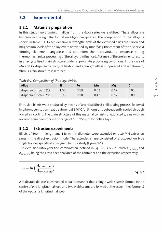
111
Microstructural and X-ray tomographic analysis of damage in weld seams
Ch
apte
r 5
5.2 Experimental
5.2.1 Materials preparationIn this study two aluminium alloys from the 6xxx series were utilised. These alloys are
hardenable through the formation Mg-Si precipitates. The composition of the alloys is
shown in Table 5-1. To achieve similar strength levels of the extruded parts the silicon and
magnesium levels of the alloys were not varied. By modifying the content of the dispersoid
forming elements manganese and chromium the microstructural response during
thermomechanical processing of the alloys is influenced. Absence of these elements results
in a recrystallised grain structure under appropriate processing conditions. In the case of
Mn and Cr dispersoids, recrystallisation and grain growth is suppressed and a deformed,
fibrous grain structure is retained.
Table 5-1 Composition of the alloys (wt-%)
Alloy Si Fe Mn Mg Cr
dispersoid-free (621) 1.00 0.19 0.02 0.67 0.01
dispersoid-rich (620) 0.98 0.18 0.47 0.67 0.09
Extrusion billets were produced by means of a vertical direct chill casting process, followed
by a homogenisation heat treatment at 540°C for 5 hours and subsequently cooled through
forced air cooling. The grain structure of this material consists of equiaxed grains with an
average grain diameter in the range of 100-150 μm for both alloys.
5.2.2 Extrusion experimentsBillets of 300 mm length and 143 mm in diameter were extruded on a 10 MN extrusion
press in the direct extrusion mode. The extruded shape consisted of a box-section type
single hollow, specifically designed for this study (Figure 5-1).
The extrusion ratio ϕ for this combination, defined in Eq. 5-1, is ϕ = 2.5 with Acontainer and
Aextrusion being the cross-sectional area of the container and the extrusion respectively.
Eq. 5-1
A dedicated die was constructed in such a manner that a single weld seam is formed in the
centre of one longitudinal web and two weld seams are formed at the extremities (corners)
of the opposite longitudinal web.
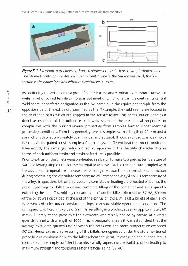
112
Weld Seams in Aluminium Alloy Extrusions: Microstructure and PropertiesC
hap
ter 5
Figure 5-1 Extrudate particulars: a shape, b dimensions and c tensile sample dimensions.
The ‘W’-web contains a central weld seam (central line in the top shaded area); the ‘T’-
section is the equivalent web without a central weld seam.
By sectioning the extrusion to a pre-defined thickness and eliminating the short transverse
webs, a set of paired tensile samples is obtained of which one sample contains a central
weld seam, henceforth designated as the ‘W’-sample. In the equivalent sample from the
opposite side of the extrusion, identified as the ‘T’-sample, the weld seams are located in
the thickened parts which are gripped in the tensile tester. This configuration enables a
direct assessment of the influence of a weld seam on the mechanical properties in
comparison with the bulk transverse properties from samples formed under identical
processing conditions. From this geometry tensile samples with a length of 90 mm and a
parallel length of approximately 50 mm are manufactured. Thickness of the tensile samples
is 5 mm. As the paired tensile samples of both alloys at different heat treatment conditions
have exactly the same geometry, a direct comparison of the ductility characteristics in
terms of both uniform strain and strain at fracture is possible.
Prior to extrusion the billets were pre-heated in a batch furnace to a pre-set temperature of
540°C, allowing ample time for the material to achieve a stable temperature. Coupled with
the additional temperature increase due to heat generation from deformation and friction
during processing, the extrudate temperature will exceed the Mg2Si-solvus temperature of
the alloys in question. Extrusion processing consisted of loading a pre-heated billet into the
press, upsetting the billet to ensure complete filling of the container and subsequently
extruding the billet. To avoid any contamination from the billet skin residue [37, 38], 30 mm
of the billet was discarded at the end of the extrusion cycle. At least 2 billets of each alloy
type were extruded under constant settings to ensure stable operational conditions. The
ram speed was fixed at a value of 5 mm/s, resulting in a product speed of approximately 60
mm/s. Directly at the press exit the extrudate was rapidly cooled by means of a water
quench tunnel with a length of 1000 mm. In preparatory tests it was established that the
average extrudate quench rate between the press exit and room temperature exceeded
30°C/s. Hence extrusion processing of the billets homogenised under the aforementioned
procedure in combination with the billet reheat temperature extrusion and quench rate is
considered to be amply sufficient to achieve a fully supersaturated solid solution, leading to
maximum strength and toughness after artificial aging [39, 40].
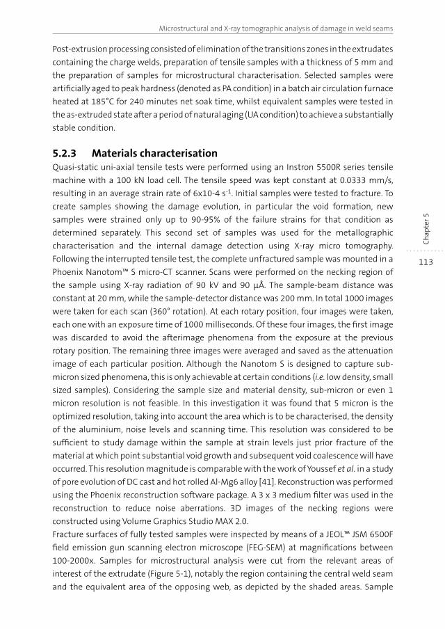
113
Microstructural and X-ray tomographic analysis of damage in weld seams
Ch
apte
r 5
Post-extrusion processing consisted of elimination of the transitions zones in the extrudates
containing the charge welds, preparation of tensile samples with a thickness of 5 mm and
the preparation of samples for microstructural characterisation. Selected samples were
artificially aged to peak hardness (denoted as PA condition) in a batch air circulation furnace
heated at 185°C for 240 minutes net soak time, whilst equivalent samples were tested in
the as-extruded state after a period of natural aging (UA condition) to achieve a substantially
stable condition.
5.2.3 Materials characterisationQuasi-static uni-axial tensile tests were performed using an Instron 5500R series tensile
machine with a 100 kN load cell. The tensile speed was kept constant at 0.0333 mm/s,
resulting in an average strain rate of 6x10⁻⁴ s-1. Initial samples were tested to fracture. To
create samples showing the damage evolution, in particular the void formation, new
samples were strained only up to 90-95% of the failure strains for that condition as
determined separately. This second set of samples was used for the metallographic
characterisation and the internal damage detection using X-ray micro tomography.
Following the interrupted tensile test, the complete unfractured sample was mounted in a
Phoenix Nanotom™ S micro-CT scanner. Scans were performed on the necking region of
the sample using X-ray radiation of 90 kV and 90 μÅ. The sample-beam distance was
constant at 20 mm, while the sample-detector distance was 200 mm. In total 1000 images
were taken for each scan (360° rotation). At each rotary position, four images were taken,
each one with an exposure time of 1000 milliseconds. Of these four images, the first image
was discarded to avoid the afterimage phenomena from the exposure at the previous
rotary position. The remaining three images were averaged and saved as the attenuation
image of each particular position. Although the Nanotom S is designed to capture sub-
micron sized phenomena, this is only achievable at certain conditions (i.e. low density, small
sized samples). Considering the sample size and material density, sub-micron or even 1
micron resolution is not feasible. In this investigation it was found that 5 micron is the
optimized resolution, taking into account the area which is to be characterised, the density
of the aluminium, noise levels and scanning time. This resolution was considered to be
sufficient to study damage within the sample at strain levels just prior fracture of the
material at which point substantial void growth and subsequent void coalescence will have
occurred. This resolution magnitude is comparable with the work of Youssef et al. in a study
of pore evolution of DC cast and hot rolled Al-Mg6 alloy [41]. Reconstruction was performed
using the Phoenix reconstruction software package. A 3 x 3 medium filter was used in the
reconstruction to reduce noise aberrations. 3D images of the necking regions were
constructed using Volume Graphics Studio MAX 2.0.
Fracture surfaces of fully tested samples were inspected by means of a JEOL™ JSM 6500F
field emission gun scanning electron microscope (FEG-SEM) at magnifications between
100-2000x. Samples for microstructural analysis were cut from the relevant areas of
interest of the extrudate (Figure 5-1), notably the region containing the central weld seam
and the equivalent area of the opposing web, as depicted by the shaded areas. Sample
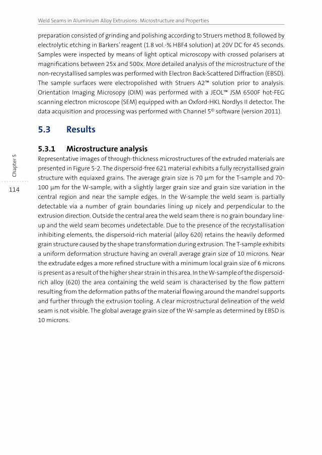
114
Weld Seams in Aluminium Alloy Extrusions: Microstructure and PropertiesC
hap
ter 5
preparation consisted of grinding and polishing according to Struers method B, followed by
electrolytic etching in Barkers’ reagent (1.8 vol.-% HBF4 solution) at 20V DC for 45 seconds.
Samples were inspected by means of light optical microscopy with crossed polarisers at
magnifications between 25x and 500x. More detailed analysis of the microstructure of the
non-recrystallised samples was performed with Electron Back-Scattered Diffraction (EBSD).
The sample surfaces were electropolished with Struers A2™ solution prior to analysis.
Orientation Imaging Microsopy (OIM) was performed with a JEOL™ JSM 6500F hot-FEG
scanning electron microscope (SEM) equipped with an Oxford-HKL Nordlys II detector. The
data acquisition and processing was performed with Channel 5© software (version 2011).
5.3 Results
5.3.1 Microstructure analysisRepresentative images of through-thickness microstructures of the extruded materials are
presented in Figure 5-2. The dispersoid-free 621 material exhibits a fully recrystallised grain
structure with equiaxed grains. The average grain size is 70 μm for the T-sample and 70-
100 μm for the W-sample, with a slightly larger grain size and grain size variation in the
central region and near the sample edges. In the W-sample the weld seam is partially
detectable via a number of grain boundaries lining up nicely and perpendicular to the
extrusion direction. Outside the central area the weld seam there is no grain boundary line-
up and the weld seam becomes undetectable. Due to the presence of the recrystallisation
inhibiting elements, the dispersoid-rich material (alloy 620) retains the heavily deformed
grain structure caused by the shape transformation during extrusion. The T-sample exhibits
a uniform deformation structure having an overall average grain size of 10 microns. Near
the extrudate edges a more refined structure with a minimum local grain size of 6 microns
is present as a result of the higher shear strain in this area. In the W-sample of the dispersoid-
rich alloy (620) the area containing the weld seam is characterised by the flow pattern
resulting from the deformation paths of the material flowing around the mandrel supports
and further through the extrusion tooling. A clear microstructural delineation of the weld
seam is not visible. The global average grain size of the W-sample as determined by EBSD is
10 microns.
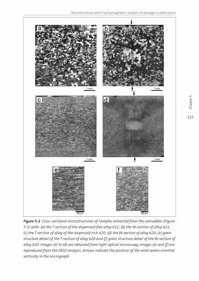
115
Microstructural and X-ray tomographic analysis of damage in weld seams
Ch
apte
r 5
Figure 5-2 Cross-sectional microstructures of samples extracted from the extrudates (Figure
5-1) with: (a) the T-section of the dispersoid-free alloy 621; (b) the W-section of alloy 621;
(c) the T-section of alloy of the dispersoid-rich 620; (d) the W-section of alloy 620; (e) grain
structure detail of the T-section of alloy 620 and (f) grain structure detail of the W-section of
alloy 620. Images (a) to (d) are obtained from light optical microscopy, images (e) and (f) are
reproduced from the EBSD analysis. Arrows indicate the position of the weld seams oriented
vertically in the micrograph.
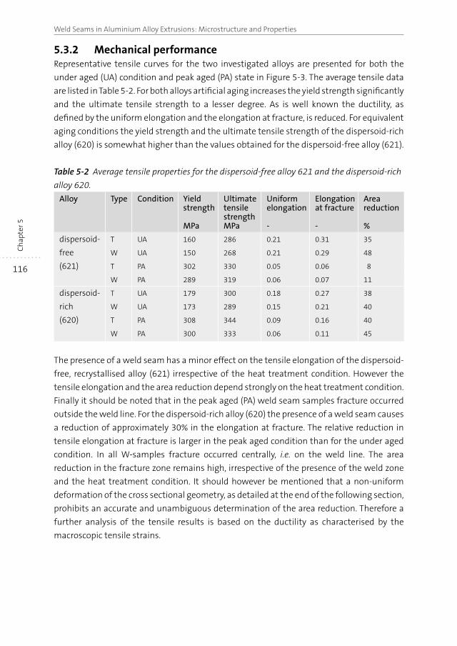
116
Weld Seams in Aluminium Alloy Extrusions: Microstructure and PropertiesC
hap
ter 5
5.3.2 Mechanical performanceRepresentative tensile curves for the two investigated alloys are presented for both the
under aged (UA) condition and peak aged (PA) state in Figure 5-3. The average tensile data
are listed in Table 5-2. For both alloys artificial aging increases the yield strength significantly
and the ultimate tensile strength to a lesser degree. As is well known the ductility, as
defined by the uniform elongation and the elongation at fracture, is reduced. For equivalent
aging conditions the yield strength and the ultimate tensile strength of the dispersoid-rich
alloy (620) is somewhat higher than the values obtained for the dispersoid-free alloy (621).
Table 5-2 Average tensile properties for the dispersoid-free alloy 621 and the dispersoid-rich
alloy 620.
Alloy Type Condition Yield strength
MPa
Ultimate tensile strength MPa
Uniform elongation
-
Elongation at fracture
-
Area reduction
%
dispersoid-
free
(621)
T UA 160 286 0.21 0.31 35
W UA 150 268 0.21 0.29 48
T PA 302 330 0.05 0.06 8
W PA 289 319 0.06 0.07 11
dispersoid-
rich
(620)
T UA 179 300 0.18 0.27 38
W UA 173 289 0.15 0.21 40
T PA 308 344 0.09 0.16 40
W PA 300 333 0.06 0.11 45
The presence of a weld seam has a minor effect on the tensile elongation of the dispersoid-
free, recrystallised alloy (621) irrespective of the heat treatment condition. However the
tensile elongation and the area reduction depend strongly on the heat treatment condition.
Finally it should be noted that in the peak aged (PA) weld seam samples fracture occurred
outside the weld line. For the dispersoid-rich alloy (620) the presence of a weld seam causes
a reduction of approximately 30% in the elongation at fracture. The relative reduction in
tensile elongation at fracture is larger in the peak aged condition than for the under aged
condition. In all W-samples fracture occurred centrally, i.e. on the weld line. The area
reduction in the fracture zone remains high, irrespective of the presence of the weld zone
and the heat treatment condition. It should however be mentioned that a non-uniform
deformation of the cross sectional geometry, as detailed at the end of the following section,
prohibits an accurate and unambiguous determination of the area reduction. Therefore a
further analysis of the tensile results is based on the ductility as characterised by the
macroscopic tensile strains.
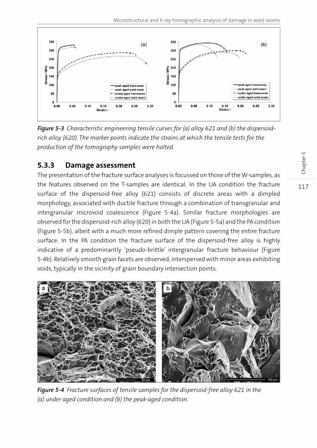
117
Microstructural and X-ray tomographic analysis of damage in weld seams
Ch
apte
r 5
Figure 5-3 Characteristic engineering tensile curves for (a) alloy 621 and (b) the dispersoid-
rich alloy (620). The marker points indicate the strains at which the tensile tests for the
production of the tomography samples were halted.
5.3.3 Damage assessmentThe presentation of the fracture surface analyses is focussed on those of the W-samples, as
the features observed on the T-samples are identical. In the UA condition the fracture
surface of the dispersoid-free alloy (621) consists of discrete areas with a dimpled
morphology, associated with ductile fracture through a combination of transgranular and
intergranular microvoid coalescence (Figure 5-4a). Similar fracture morphologies are
observed for the dispersoid-rich alloy (620) in both the UA (Figure 5-5a) and the PA condition
(Figure 5-5b), albeit with a much more refined dimple pattern covering the entire fracture
surface. In the PA condition the fracture surface of the dispersoid-free alloy is highly
indicative of a predominantly ‘pseudo-brittle’ intergranular fracture behaviour (Figure
5-4b). Relatively smooth grain facets are observed, interspersed with minor areas exhibiting
voids, typically in the vicinity of grain boundary intersection points.
Figure 5-4 Fracture surfaces of tensile samples for the dispersoid-free alloy 621 in the
(a) under aged condition and (b) the peak-aged condition.
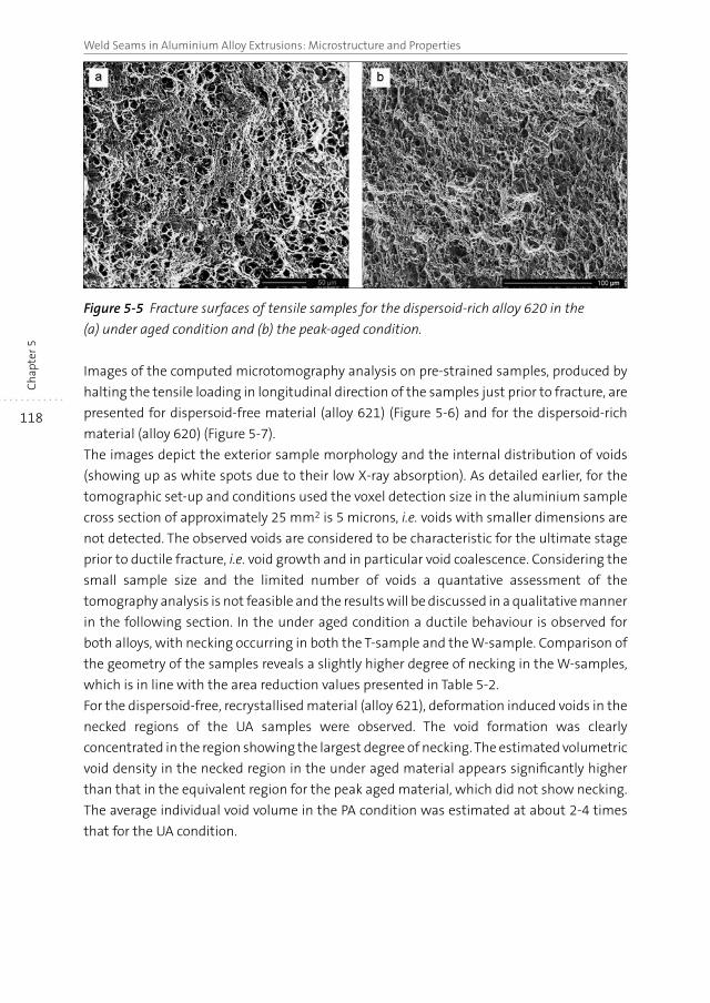
118
Weld Seams in Aluminium Alloy Extrusions: Microstructure and PropertiesC
hap
ter 5
Figure 5-5 Fracture surfaces of tensile samples for the dispersoid-rich alloy 620 in the
(a) under aged condition and (b) the peak-aged condition.
Images of the computed microtomography analysis on pre-strained samples, produced by
halting the tensile loading in longitudinal direction of the samples just prior to fracture, are
presented for dispersoid-free material (alloy 621) (Figure 5-6) and for the dispersoid-rich
material (alloy 620) (Figure 5-7).
The images depict the exterior sample morphology and the internal distribution of voids
(showing up as white spots due to their low X-ray absorption). As detailed earlier, for the
tomographic set-up and conditions used the voxel detection size in the aluminium sample
cross section of approximately 25 mm2 is 5 microns, i.e. voids with smaller dimensions are
not detected. The observed voids are considered to be characteristic for the ultimate stage
prior to ductile fracture, i.e. void growth and in particular void coalescence. Considering the
small sample size and the limited number of voids a quantative assessment of the
tomography analysis is not feasible and the results will be discussed in a qualitative manner
in the following section. In the under aged condition a ductile behaviour is observed for
both alloys, with necking occurring in both the T-sample and the W-sample. Comparison of
the geometry of the samples reveals a slightly higher degree of necking in the W-samples,
which is in line with the area reduction values presented in Table 5-2.
For the dispersoid-free, recrystallised material (alloy 621), deformation induced voids in the
necked regions of the UA samples were observed. The void formation was clearly
concentrated in the region showing the largest degree of necking. The estimated volumetric
void density in the necked region in the under aged material appears significantly higher
than that in the equivalent region for the peak aged material, which did not show necking.
The average individual void volume in the PA condition was estimated at about 2-4 times
that for the UA condition.
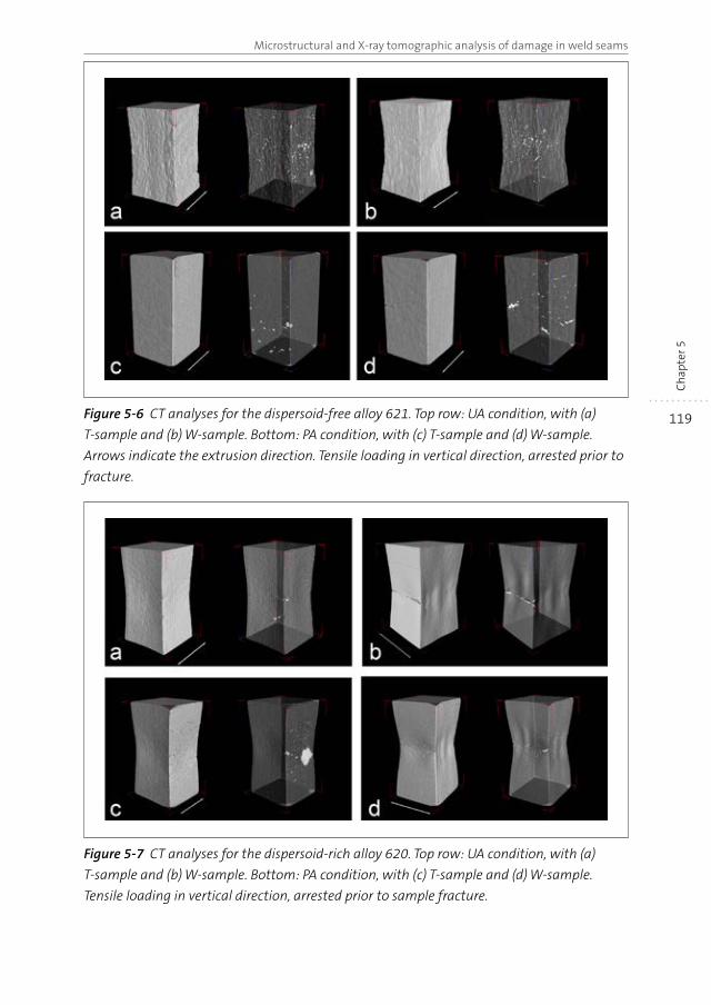
119
Microstructural and X-ray tomographic analysis of damage in weld seams
Ch
apte
r 5
Figure 5-6 CT analyses for the dispersoid-free alloy 621. Top row: UA condition, with (a)
T-sample and (b) W-sample. Bottom: PA condition, with (c) T-sample and (d) W-sample.
Arrows indicate the extrusion direction. Tensile loading in vertical direction, arrested prior to
fracture.
Figure 5-7 CT analyses for the dispersoid-rich alloy 620. Top row: UA condition, with (a)
T-sample and (b) W-sample. Bottom: PA condition, with (c) T-sample and (d) W-sample.
Tensile loading in vertical direction, arrested prior to sample fracture.
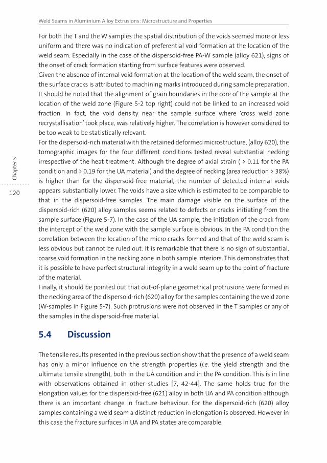
120
Weld Seams in Aluminium Alloy Extrusions: Microstructure and PropertiesC
hap
ter 5
For both the T and the W samples the spatial distribution of the voids seemed more or less
uniform and there was no indication of preferential void formation at the location of the
weld seam. Especially in the case of the dispersoid-free PA-W sample (alloy 621), signs of
the onset of crack formation starting from surface features were observed.
Given the absence of internal void formation at the location of the weld seam, the onset of
the surface cracks is attributed to machining marks introduced during sample preparation.
It should be noted that the alignment of grain boundaries in the core of the sample at the
location of the weld zone (Figure 5-2 top right) could not be linked to an increased void
fraction. In fact, the void density near the sample surface where ‘cross weld zone
recrystallisation’ took place, was relatively higher. The correlation is however considered to
be too weak to be statistically relevant.
For the dispersoid-rich material with the retained deformed microstructure, (alloy 620), the
tomographic images for the four different conditions tested reveal substantial necking
irrespective of the heat treatment. Although the degree of axial strain ( > 0.11 for the PA
condition and > 0.19 for the UA material) and the degree of necking (area reduction > 38%)
is higher than for the dispersoid-free material, the number of detected internal voids
appears substantially lower. The voids have a size which is estimated to be comparable to
that in the dispersoid-free samples. The main damage visible on the surface of the
dispersoid-rich (620) alloy samples seems related to defects or cracks initiating from the
sample surface (Figure 5-7). In the case of the UA sample, the initiation of the crack from
the intercept of the weld zone with the sample surface is obvious. In the PA condition the
correlation between the location of the micro cracks formed and that of the weld seam is
less obvious but cannot be ruled out. It is remarkable that there is no sign of substantial,
coarse void formation in the necking zone in both sample interiors. This demonstrates that
it is possible to have perfect structural integrity in a weld seam up to the point of fracture
of the material.
Finally, it should be pointed out that out-of-plane geometrical protrusions were formed in
the necking area of the dispersoid-rich (620) alloy for the samples containing the weld zone
(W-samples in Figure 5-7). Such protrusions were not observed in the T samples or any of
the samples in the dispersoid-free material.
5.4 Discussion
The tensile results presented in the previous section show that the presence of a weld seam
has only a minor influence on the strength properties (i.e. the yield strength and the
ultimate tensile strength), both in the UA condition and in the PA condition. This is in line
with observations obtained in other studies [7, 42-44]. The same holds true for the
elongation values for the dispersoid-free (621) alloy in both UA and PA condition although
there is an important change in fracture behaviour. For the dispersoid-rich (620) alloy
samples containing a weld seam a distinct reduction in elongation is observed. However in
this case the fracture surfaces in UA and PA states are comparable.
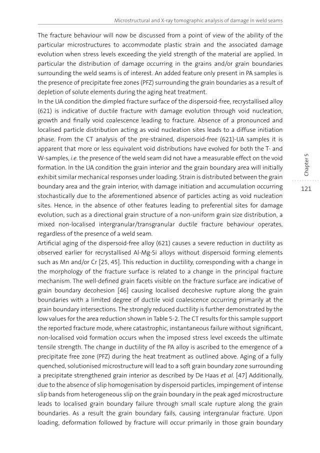
121
Microstructural and X-ray tomographic analysis of damage in weld seams
Ch
apte
r 5
The fracture behaviour will now be discussed from a point of view of the ability of the
particular microstructures to accommodate plastic strain and the associated damage
evolution when stress levels exceeding the yield strength of the material are applied. In
particular the distribution of damage occurring in the grains and/or grain boundaries
surrounding the weld seams is of interest. An added feature only present in PA samples is
the presence of precipitate free zones (PFZ) surrounding the grain boundaries as a result of
depletion of solute elements during the aging heat treatment.
In the UA condition the dimpled fracture surface of the dispersoid-free, recrystallised alloy
(621) is indicative of ductile fracture with damage evolution through void nucleation,
growth and finally void coalescence leading to fracture. Absence of a pronounced and
localised particle distribution acting as void nucleation sites leads to a diffuse initiation
phase. From the CT analysis of the pre-strained, dispersoid-free (621)-UA samples it is
apparent that more or less equivalent void distributions have evolved for both the T- and
W-samples, i.e. the presence of the weld seam did not have a measurable effect on the void
formation. In the UA condition the grain interior and the grain boundary area will initially
exhibit similar mechanical responses under loading. Strain is distributed between the grain
boundary area and the grain interior, with damage initiation and accumulation occurring
stochastically due to the aforementioned absence of particles acting as void nucleation
sites. Hence, in the absence of other features leading to preferential sites for damage
evolution, such as a directional grain structure of a non-uniform grain size distribution, a
mixed non-localised intergranular/transgranular ductile fracture behaviour operates,
regardless of the presence of a weld seam.
Artificial aging of the dispersoid-free alloy (621) causes a severe reduction in ductility as
observed earlier for recrystallised Al-Mg-Si alloys without dispersoid forming elements
such as Mn and/or Cr [25, 45]. This reduction in ductility, corresponding with a change in
the morphology of the fracture surface is related to a change in the principal fracture
mechanism. The well-defined grain facets visible on the fracture surface are indicative of
grain boundary decohesion [46] causing localised decohesive rupture along the grain
boundaries with a limited degree of ductile void coalescence occurring primarily at the
grain boundary intersections. The strongly reduced ductility is further demonstrated by the
low values for the area reduction shown in Table 5-2. The CT results for this sample support
the reported fracture mode, where catastrophic, instantaneous failure without significant,
non-localised void formation occurs when the imposed stress level exceeds the ultimate
tensile strength. The change in ductility of the PA alloy is ascribed to the emergence of a
precipitate free zone (PFZ) during the heat treatment as outlined above. Aging of a fully
quenched, solutionised microstructure will lead to a soft grain boundary zone surrounding
a precipitate strengthened grain interior as described by De Haas et al. [47] Additionally,
due to the absence of slip homogenisation by dispersoid particles, impingement of intense
slip bands from heterogeneous slip on the grain boundary in the peak aged microstructure
leads to localised grain boundary failure through small scale rupture along the grain
boundaries. As a result the grain boundary fails, causing intergranular fracture. Upon
loading, deformation followed by fracture will occur primarily in those grain boundary
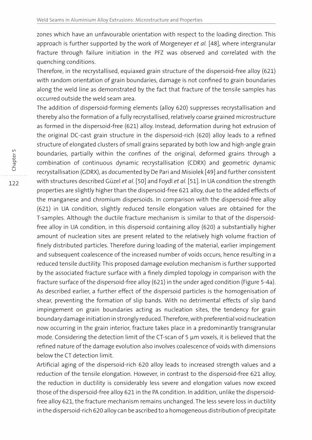
122
Weld Seams in Aluminium Alloy Extrusions: Microstructure and PropertiesC
hap
ter 5
zones which have an unfavourable orientation with respect to the loading direction. This
approach is further supported by the work of Morgeneyer et al. [48], where intergranular
fracture through failure initiation in the PFZ was observed and correlated with the
quenching conditions.
Therefore, in the recrystallised, equiaxed grain structure of the dispersoid-free alloy (621)
with random orientation of grain boundaries, damage is not confined to grain boundaries
along the weld line as demonstrated by the fact that fracture of the tensile samples has
occurred outside the weld seam area.
The addition of dispersoid-forming elements (alloy 620) suppresses recrystallisation and
thereby also the formation of a fully recrystallised, relatively coarse grained microstructure
as formed in the dispersoid-free (621) alloy. Instead, deformation during hot extrusion of
the original DC-cast grain structure in the dispersoid-rich (620) alloy leads to a refined
structure of elongated clusters of small grains separated by both low and high-angle grain
boundaries, partially within the confines of the original, deformed grains through a
combination of continuous dynamic recrystallisation (CDRX) and geometric dynamic
recrystallisation (GDRX), as documented by De Pari and Misiolek [49] and further consistent
with structures described Güzel et al. [50] and Foydl et al. [51]. In UA condition the strength
properties are slightly higher than the dispersoid-free 621 alloy, due to the added effects of
the manganese and chromium dispersoids. In comparison with the dispersoid-free alloy
(621) in UA condition, slightly reduced tensile elongation values are obtained for the
T-samples. Although the ductile fracture mechanism is similar to that of the dispersoid-
free alloy in UA condition, in this dispersoid containing alloy (620) a substantially higher
amount of nucleation sites are present related to the relatively high volume fraction of
finely distributed particles. Therefore during loading of the material, earlier impingement
and subsequent coalescence of the increased number of voids occurs, hence resulting in a
reduced tensile ductility. This proposed damage evolution mechanism is further supported
by the associated fracture surface with a finely dimpled topology in comparison with the
fracture surface of the dispersoid-free alloy (621) in the under aged condition (Figure 5-4a).
As described earlier, a further effect of the dispersoid particles is the homogenisation of
shear, preventing the formation of slip bands. With no detrimental effects of slip band
impingement on grain boundaries acting as nucleation sites, the tendency for grain
boundary damage initiation in strongly reduced. Therefore, with preferential void nucleation
now occurring in the grain interior, fracture takes place in a predominantly transgranular
mode. Considering the detection limit of the CT-scan of 5 μm voxels, it is believed that the
refined nature of the damage evolution also involves coalescence of voids with dimensions
below the CT detection limit.
Artificial aging of the dispersoid-rich 620 alloy leads to increased strength values and a
reduction of the tensile elongation. However, in contrast to the dispersoid-free 621 alloy,
the reduction in ductility is considerably less severe and elongation values now exceed
those of the dispersoid-free alloy 621 in the PA condition. In addition, unlike the dispersoid-
free alloy 621, the fracture mechanism remains unchanged. The less severe loss in ductility
in the dispersoid-rich 620 alloy can be ascribed to a homogeneous distribution of precipitate
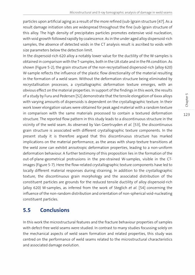
123
Microstructural and X-ray tomographic analysis of damage in weld seams
Ch
apte
r 5
particles upon artificial aging as a result of the more refined (sub-)grain structure [47]. As a
result damage initiation sites are widespread throughout the fine (sub-)grain structure of
this alloy. The high density of precipitates particles promotes extensive void nucleation,
with void growth followed rapidly by coalescence. As in the under aged alloy dispersoid-rich
samples, the absence of detected voids in the CT analysis result is ascribed to voids with
size parameters below the detection limit.
In the dispersoid-rich 620 alloy a notably lower value for the ductility of the W-samples is
obtained in comparison with the T-samples, both in the UA state and in the PA condition. As
shown (Figure 5-2), the grain structure of the non-recrystallised dispersoid-rich (alloy 620)
W-sample reflects the influence of the plastic flow directionality of the material resulting
in the formation of a weld seam. Without the deformation structure being eliminated by
recrystallisation processes, a crystallographic deformation texture emerges, with an
obvious effect on the material properties. In support of the findings in this work, the results
of a study by Furu and Pedersen [52] demonstrate that the tensile elongation of 6xxx alloys
with varying amounts of dispersoids is dependent on the crystallographic texture. In their
work lower elongation values were obtained for peak aged material with a random texture
in comparison with the same materials processed to contain a textured deformation
structure. The reported flow pattern in this study leads to a discontinuous structure in the
vicinity of the weld seam. As observed by Van Geertruyden et al. [53], the discontinuous
grain structure is associated with different crystallographic texture components. In the
present study it is therefore argued that this discontinuous structure has marked
implications on the material performance, as the areas with sharp texture transitions at
the weld zone can exhibit anisotropic deformation properties, leading to a non-uniform
deformation behaviour. A further testimony of this proposition lies in the formation of the
out-of-plane-geometrical protrusions in the pre-strained W-samples, visible in the CT-
images (Figure 5-7). Here the flow-related crystallographic texture components have led to
locally different material responses during straining. In addition to the crystallographic
texture, the discontinuous grain morphology and the associated distribution of the
constituent particles are grounds for the reduced tensile ductility of alloy dispersoid-rich
(alloy 620) W-samples, as inferred from the work of Steglich et al. [54] concerning the
influence of the non-random distribution and orientation of non-spherical void-nucleating
constituent particles.
5.5 Conclusions
In this work the microstructural features and the fracture behaviour properties of samples
with defect-free weld seams were studied. In contrast to many studies focussing solely on
the mechanical aspects of weld seam formation and related properties, this study was
centred on the performance of weld seams related to the microstructural characteristics
and associated damage evolution.
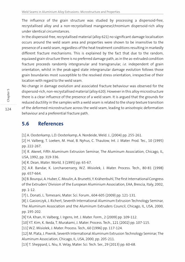
124
Weld Seams in Aluminium Alloy Extrusions: Microstructure and PropertiesC
hap
ter 5
The influence of the grain structure was studied by processing a dispersoid-free,
recrystallised alloy and a non-recrystallised manganese/chromium dispersoid-rich alloy
under identical circumstances.
In the dispersoid-free, recrystallised material (alloy 621) no significant damage localisation
occurs around the weld seam area and properties were shown to be insensitive to the
presence of a weld seam, regardless of the heat treatment conditions resulting in markedly
different fracture mechanisms. This is explained by the fact that due to the random,
equiaxed grain structure there is no preferred damage path, as in the as-extruded condition
fracture proceeds randomly intergranular and transgranular, i.e. independent of grain
orientation, whilst in the peak-aged state intergranular damage evolution follows those
grain boundaries most susceptible to the resolved stress orientation, irrespective of their
location with regard to the weld seam.
No change in damage evolution and associated fracture behaviour was observed for the
dispersoid-rich, non-recrystallised material (alloy 620). However in this alloy microstructure
there is a clear influence of the presence of a weld seam. It is argued that the grounds for
reduced ductility in the samples with a weld seam is related to the sharp texture transition
of the deformed microstructure across the weld seam, leading to anisotropic deformation
behaviour and a preferential fracture path.
5.6 References
[1] A. Oosterkamp, L.D. Oosterkamp, A. Nordeide, Weld. J., (2004) pp. 255-261.
[2] H. Valberg, T. Loeken, M. Hval, B. Nyhus, C. Thaulow, Int. J. Mater. Prod. Tec., 10 (1995)
pp. 222-267.
[3] R. Akeret, Fifth Aluminum Extrusion Seminar, The Aluminum Association, Chicago, IL,
USA, 1992, pp. 319-336.
[4] R. Dean, Mater. World, 3 (1995) pp. 65-67.
[5] A.R. Bandar, K. Lorcharoensery, W.Z. Misiolek, J. Mater. Process. Tech., 80-81 (1998)
pp. 657-664.
[6] B. Bourqui, A. Huber, C. Moulin, A. Brunetti, Y. Krähenbuhl, The first International Congress
of the Extruders’ Division of the European Aluminium Association, EAA, Brescia, Italy, 2002,
pp. 1-12.
[7] L. Donati, L. Tomesani, Mater. Sci. Forum., 604-605 (2009) pp. 121-131.
[8] J. Gasiorczyk, J. Richert, Seventh International Aluminum Extrusion Technology Seminar,
The Aluminum Association and the Aluminum Extruders Council, Chicago, IL, USA, 2000,
pp. 195-202.
[9] Y.A. Khan, H. Valberg, I. Irgens, Int. J. Mater. Form., 2 (2009) pp. 109-112.
[10] Y.T. Kim, K. Ikeda, T. Murakami, J. Mater. Process. Tech., 121 (2002) pp. 107-115.
[11] W.Z. Misiolek, J. Mater. Process. Tech., 60 (1996) pp. 117-124.
[12] M. Plata, J. Piwnik, Seventh International Aluminum Extrusion Technology Seminar, The
Aluminum Association, Chicago, IL, USA, 2000, pp. 205-211.
[13] T. Sheppard, L. Niu, X. Velay, Mater. Sci. Tech. Ser., 29 (2013) pp. 60-68.
125
Microstructural and X-ray tomographic analysis of damage in weld seams
Ch
apte
r 5
[14] H. Valberg, T. Malvik, Int. J. Mater. Prod. Tec., 9 (1994) pp. 428-462.
[15] J.X. Xie, T. Murakami, K. Ikeda, H. Takahashi, J. Mater. Process. Tech., 49 (1995) pp. 1-11.
[16] J. Gasiorczyk, J. Richert, Seventh International Aluminum Extrusion Technology Seminar,
The Aluminum Association, Chicago, IL, USA, 2000, pp. 195-202.
[17] K.B. Muller, U. Winsemann, Aluminium, 79 (2003) pp. 264-268.
[18] W.M. Garrison Jr, N.R. Moody, J. Phys. Chem. Solids., 48 (1987) pp. 1035-1074.
[19] R.H. VanStone, T.B. Cox, J.R. Low, J.A. Psioda, Int. Mater. Rev., 30 (1985) pp. 157-180.
[20] P.F. Thomason, Ductile Fracture of Metals, 1st ed., Pergamon Press, Oxford, (1990).
[21] H. Toda, H. Oogo, K. Horikawa, K. Uesugi, A. Takeuchi, Y. Suzuki, M. Nakazawa, Y. Aoki,
M. Kobayashi, Metallurgical and Materials Transactions A, 45 (2014) pp. 765-776.
[22] D. Broek, Eng. Fract. Mech., 5 (1973) 55-56, IN51-IN56, pp. 57-66.
[23] J.M. Dowling, J.W. Martin, Acta. Metall. Mater., 24 (1976) pp. 1147-1153.
[24] J.M. Dowling, D.C. Martin, in: D.M.R. Taplin (Ed.) Fracture 1977, University of Waterloo,
Waterloo, Canada, (1977), pp. 87-95.
[25] A.K. Busby, L. Edwards, J.W. Martin, Mater. Sci. Tech. Ser., 2 (1986) pp. 363-367.
[26] A.K. Vasudévan, R.D. Doherty, Acta. Metall. Mater., 35 (1987) pp. 1193-1219.
[27] J.D. Embury, E. Nes, Z.Metallkunde, 65 (1974) pp. 45-55.
[28] T. Pardoen, D. Dumont, A. Deschamps, Y. Brechet, J. Mech. Phys. Solids., 51 (2003)
pp. 637-665.
[29] D.S. MacKenzie, Mechanical Properties, in: G.E. Totten, D.S. MacKenzie (Eds.) Handbook
of Aluminum, CRC Press, New York, 2003, pp. 353-354.
[30] R. Zhao, S. Zhao, J. Guo, B. Zhong, J. Li, Mater. Sci. Tech. Ser., 31 (2015), pp. 303-309.
[31] E. Sweet, S.K. Caraher, N.V. Danilova, X. Zhang, Eight International Aluminum Extrusion
Technology Seminar, ET Foundation / The Aluminum Association, Orlando, FL, USA, 2004,
pp. 115-126.
[32] F.J. Humphreys, M. Hatherly, Recrystallization and Related Annealing Phenomena,
Elsevier, Oxford, 2004.
[33] E. Nes, Acta. Metall. Mater., 24 (1976) pp. 391-398.
[34] R. Hu, T. Ogura, H. Tezuka, T. Sato, Q. Liu, J. Mater. Sci. Technol., 26 (2010) pp. 237-243.
[35] F. Hichem, G.D. Eddine, D. Karim, G. Rebai, S. Fares, Global Journal of Science Frontier
Research Physics & Space Science, 12 (2012).
[36] L. Lodgaard, N. Ryum, Mat. Sci. Eng. A-Struct., 283 (2000) pp. 144-152.
[37] C. Jowett, N. Parson, W. Fraser, J. Hankin, K. Hicklin, Seventh International Aluminum
Extrusion Technology Seminar, The Aluminum Association, Chicago, IL, USA, 2000, pp. 27-42.
[38] M. Lefstad, O. Reiso, V. Johnson, Fifth International Aluminum Extrusion Technology
Seminar, The Aluminum Association, Chicago, IL, USA, 1992, pp. 503-516.
[39] Y. Birol, Mater. Sci. Tech. Ser., 29 (2013) pp. 1518-1521.
[40] S. Zajac, B. Bengtsson, C. Jonsson, A. Isaksson, Seventh International Aluminum
Extrusion Technology Seminar, The Aluminum Association, Chicago, IL, USA, 2000, pp. 82.
[41] Y.M. Youssef, A. Chaijaruwanich, R.W. Hamilton, H. Nagaumi, R.J. Dashwood, P.D. Lee,
Mater. Sci. Tech. Ser., 22 (2006) pp. 1087-1092.
126
Weld Seams in Aluminium Alloy Extrusions: Microstructure and PropertiesC
hap
ter 5
[42] A.J. Den Bakker, S.P. Edwards, L. ‘t Hoen-Verlterop, R. Ubels, Ninth International
Aluminum Extrusion Technology Seminar, The Aluminum Association, Orlando, FL, USA,
2008.
[43] K.B. Muller, U. Winsemann, Aluminium, 79 (2003) pp. 530-540.
[44] N. Nanninga, C. White, T. Furu, O. Anderson, R. Dickson, Int. J. Fatigue, 30 (2008)
pp. 1569-1578.
[45] T. Uno, Y. Baba, J. Jpn. I. Met., 45 (1981) pp. 405-410.
[46] E. Iesulauro, Decohesion of grain boundaries in three-dimensional statistical
representations of aluminum polycrystals, Doctoral Thesis Cornell Fracture Group, Cornell
University, Ithaca, NY, USA, 2006, pp. 226.
[47] M. De Haas, J.T.M. De Hosson, J. Mater. Sci., 37 (2002) pp. 5065-5073.
[48] T.F. Morgeneyer, M.J. Starink, S.C. Wang, I. Sinclair, Acta mater., 56 (2008) pp. 2872-2884.
[49] L. De Pari, W.Z. Misiolek, Acta mater., 56 (2008) pp. 6174-6185.
[50] A. Güzel, A. Jeager, F. Parvizian, H.G. Lambers, A.E. Tekkaya, B. Svendsen, H.J. Maier,
J. Mater. Process. Tech., 212 (2012) pp. 323-330.
[51] A. Foydl, A. Segatori, N. Ben Khalifa, L. Donati, A. Brosius, L. Tomesani, A.E. Tekkaya, Mater.
Sci. Tech. Ser., 29 (2013) pp. 100-110.
[52] T. Furu, K.O. Pedersen, Mater. Sci. Forum., 519-521 (2006) pp. 1421-1428.
[53] W.H.v. Geertruyden, S.R. Claves, W.Z. Misiolek, Metall. Mater. Trans. A, 33 (2002) pp. 693-
700.
[54] D. Steglich, W. Brocks, J. Heerens, T. Pardoen, Eng. Fract. Mech., 75 (2008) pp. 3692-3706.
CHAPTER 6
The origin of weld seam defects related to metal flow in the hot extrusion of aluminium alloys EN AW-6060 and EN AW-6082 7
Abstract
Longitudinal weld seams are an intrinsic feature in hollow extrusions produced with porthole
dies. As these joins occur along the entire extruded length, it is desirable that these weld
seams have a minimal impact on the structural integrity of the extrudate. In particular,
defects associated with weld seam formation should be avoided. In this research, the
occurrence of defects related to material flow inside the extrusion tooling is studied. In lab-
scale experiments, EN AW-6060 and EN AW-6082 aluminium alloy billets are formed into
strips by means of the direct hot extrusion process. By utilising model dies with an internal
obstruction similar to the supports present in porthole dies, a strip with a central longitudinal
weld seam is formed. The effects of different geometries of the weld-chamber and the
processing conditions on the quality of the weld seam are investigated. Characterisation is
performed through mechanical testing, focusing on the ability of the weld seam area to
accommodate plastic deformation, and microstructural analysis provides insight into the
defects related to unsound metal flow. Through computer simulations, conditions related to
weld seam formation are modelled and correlated with the experimental results. The
experimental results demonstrate that metal flow controlled by the die geometry causes
defects leading to inferior mechanical performance of the extrudate. It is further argued that
current weld seam formation criteria utilised in finite element modelling need enhancement
to incorporate these flow related defects.
7 Based on the following publication: A.J. Den Bakker, R.J. Werkhoven, W.H. Sillekens, L. Katgerman, J.
Mater. Process. Tech., 214 (2014), pp. 2349-2358.
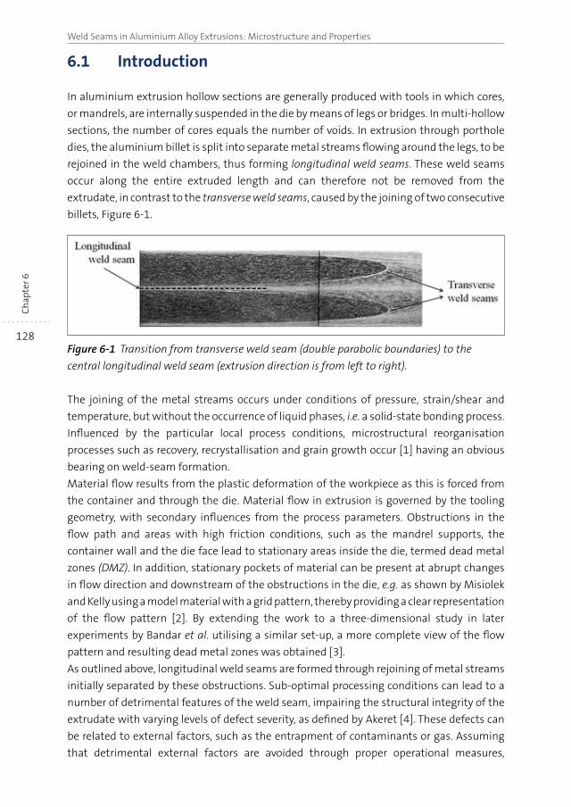
128
Weld Seams in Aluminium Alloy Extrusions: Microstructure and PropertiesC
hap
ter 6
6.1 Introduction
In aluminium extrusion hollow sections are generally produced with tools in which cores,
or mandrels, are internally suspended in the die by means of legs or bridges. In multi-hollow
sections, the number of cores equals the number of voids. In extrusion through porthole
dies, the aluminium billet is split into separate metal streams flowing around the legs, to be
rejoined in the weld chambers, thus forming longitudinal weld seams. These weld seams
occur along the entire extruded length and can therefore not be removed from the
extrudate, in contrast to the transverse weld seams, caused by the joining of two consecutive
billets, Figure 6-1.
Figure 6-1 Transition from transverse weld seam (double parabolic boundaries) to the
central longitudinal weld seam (extrusion direction is from left to right).
The joining of the metal streams occurs under conditions of pressure, strain/shear and
temperature, but without the occurrence of liquid phases, i.e. a solid-state bonding process.
Influenced by the particular local process conditions, microstructural reorganisation
processes such as recovery, recrystallisation and grain growth occur [1] having an obvious
bearing on weld-seam formation.
Material flow results from the plastic deformation of the workpiece as this is forced from
the container and through the die. Material flow in extrusion is governed by the tooling
geometry, with secondary influences from the process parameters. Obstructions in the
flow path and areas with high friction conditions, such as the mandrel supports, the
container wall and the die face lead to stationary areas inside the die, termed dead metal
zones (DMZ). In addition, stationary pockets of material can be present at abrupt changes
in flow direction and downstream of the obstructions in the die, e.g. as shown by Misiolek
and Kelly using a model material with a grid pattern, thereby providing a clear representation
of the flow pattern [2]. By extending the work to a three-dimensional study in later
experiments by Bandar et al. utilising a similar set-up, a more complete view of the flow
pattern and resulting dead metal zones was obtained [3].
As outlined above, longitudinal weld seams are formed through rejoining of metal streams
initially separated by these obstructions. Sub-optimal processing conditions can lead to a
number of detrimental features of the weld seam, impairing the structural integrity of the
extrudate with varying levels of defect severity, as defined by Akeret [4]. These defects can
be related to external factors, such as the entrapment of contaminants or gas. Assuming
that detrimental external factors are avoided through proper operational measures,
129
Weld Seam Defects Related to Metal Flow
Ch
apte
r 6
appropriate flow conditions are of primary importance in order to establish and maintain
contact of the material on the bond plane, resulting in weld seams.
Under unfavourable flow conditions, so called ‘kissing bonds’ may occur: a term initially
describing an interfacial defect in adhesively bonded structures where there is intimate
contact between surfaces but with little bonding [5]. This term was later adopted by
Oosterkamp et al. [6], referring to similar zero volume interface defects occurring in metallic
bonds formed in extrusion and friction stir welding. In more severe cases, where insufficient
transverse flow occurs behind an obstruction or a DMZ, full rejoining of the metal streams
is hindered and partially bonded areas lacking ‘metallic bonding’ are formed due to the
formation of gas pockets in the die as described by Akeret [7]. The occurrence of gas pockets
at the downstream position of the mandrel supports and the detrimental effect on weld
seam bonding was further demonstrated by Valberg et al. [8] in a series of experiments
with a modular die set-up enabling the geometry of the weld chamber to be changed. In
these cases the defect is uniquely related to the flow pattern in a particular die. Elaboration
of this work by Bariani et al. [9] includes the effect of process conditions on the contact
behaviour between the aluminium and the mandrel supports, with sticking friction leading
to full initial contact of the metal streams or sliding friction resulting in a gas pocket before
the metal streams rejoin. Finally, with further exacerbated flow conditions, rejoining of the
metal streams is impaired to the point that the gas pocket extends throughout the entire
flow path from the weld chamber to the die exit, resulting in a void in the interior of the
extrudate cross section.
Several methods have been proposed to predict weld seam performance. These methods
are largely based on the pressure acting on the bond plane combined with flow-related
features, like the residence time in the weld chamber as initially postulated by Akeret [7] .
Numerical methods are utilised to calculate the relevant input values for weld seam quality
criteria, such as originally developed by Plata and Piwnik [10]. Subsequent derivatives of
this criterion were developed, [11] with the introduction of a velocity correction factor for
different welding paths and [12] with the introduction of a critical welding indicator
implemented in finite element simulations. In a general sense these criteria predict
improved weld seam performance for higher interfacial pressure levels and/or longer
bonding paths (equivalent to increased bonding times when transit speed through the
welding chamber remains unchanged). Although trends can be extracted from these
criteria, calibration with experimental data obtained under similar conditions remains
necessary to arrive at a quantified assessment of weld seam quality. Moreover, local effects
such as the occurrence of a gas pocket as described above, are not captured, as these criteria
represent a global value for the entire weld seam in question.
As the constitutive behaviour of the material can impact the flow pattern, the occurrence
of flow-related defects must be considered in connection with the specific alloy being
processed. Insight into the influence of the die on the prevention of flow-related defects
can then aid the optimisation of the tooling geometry for the production of sound structural
hollow extrusions. In the laboratory-scale extrusion experiments described below, attention
is focussed on the flow characteristics related to weld seam defects. Additionally the effect
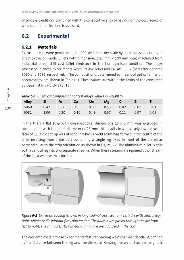
130
Weld Seams in Aluminium Alloy Extrusions: Microstructure and PropertiesC
hap
ter 6
of process conditions combined with the constitutive alloy behaviour on the occurrence of
weld seam imperfections is assessed.
6.2 Experimental
6.2.1 MaterialsExtrusion tests were performed on a 500 kN laboratory-scale hydraulic press operating in
direct extrusion mode. Billets with dimensions Ø25 mm × 100 mm were machined from
industrial direct chill cast billet feedstock in the homogenised condition. The alloys
processed in these experiments were EN AW-6060 and EN AW-6082 (hereafter denoted
6060 and 6082, respectively). The compositions, determined by means of optical emission
spectroscopy, are shown in Table 6-1. These values are within the limits of the concerned
European standard EN 573 [13].
Table 6-1 Chemical compositions of test alloys, values in weight %
Alloy Si Fe Cu Mn Mg Cr Zn Ti
6060 0.42 0.20 0.03 0.03 0.53 0.02 0.02 0.01
6082 1.00 0.20 0.10 0.49 0.67 0.11 0.07 0.03
In the trials a flat strip with cross-sectional dimensions 15 x 3 mm was extruded. In
combination with the billet diameter of 25 mm this results in a relatively low extrusion
ratio of 11. A die set-up was utilised in which a weld seam was formed in the centre of the
strip, resulting from a die part containing a single leg fixed in front of the die plate,
perpendicular to the strip orientation as shown in Figure 6-2. The aluminium billet is split
by the central leg into two separate streams. When these streams are rejoined downstream
of the leg a weld seam is formed.
Figure 6-2 Extrusion tooling (shown in longitudinal cross section). Left: die with central leg;
right: reference die without flow obstruction. The aluminium passes through the die from
left to right. The characteristic dimensions h and d are discussed in the text
The dies employed in these experiments featured varying weld chamber depths, d, defined
as the distance between the leg and the die plate. Keeping the weld chamber height, h,
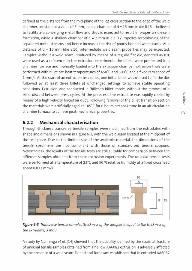
131
Weld Seam Defects Related to Metal Flow
Ch
apte
r 6
defined as the distance from the mid-plane of the leg cross section to the edge of the weld
chamber, constant at a value of 5 mm, a deep chamber of d = 15 mm in die B.15 is believed
to facilitate a converging metal flow and thus is expected to result in proper weld-seam
formation, while a shallow chamber of d = 2 mm in die B.2 impedes recombining of the
separated metal streams and hence increases the risk of poorly bonded weld seams. At a
distance of d = 10 mm (die B.10) intermediate weld seam properties may be expected.
Samples without a weld seam, produced by means of a regular flat die, denoted as B.0,
were used as a reference. In the extrusion experiments the billets were pre-heated in a
chamber furnace and manually loaded into the extrusion chamber. Extrusion trials were
performed with billet pre-heat temperatures of 450°C and 500°C and a fixed ram speed of
1 mm/s. At the start of an extrusion test series, one initial billet was utilised to fill the die,
followed by at least three billets at unchanged settings to achieve stable operating
conditions. Extrusion was conducted in ‘billet-to-billet’ mode, without the removal of a
billet discard between press cycles. At the press exit the extrudate was rapidly cooled by
means of a high velocity forced air duct. Following removal of the billet transition section
the materials were artificially aged at 185°C for 6 hours net soak time in an air circulation
chamber furnace to achieve peak mechanical properties.
6.2.2 Mechanical characterisationThrough-thickness transverse tensile samples were machined from the extrudates with
shape and dimensions shown in Figure 6-3, with the weld seam located at the midpoint of
the test piece. Due to the limited size of the available material, the dimensions of the
tensile specimens are not compliant with those of standardised tensile coupons.
Nevertheless, the results of the tensile tests are still suitable for comparison between the
different samples obtained from these extrusion experiments. The uniaxial tensile tests
were performed at a temperature of 23°C and 50 % relative humidity at a fixed crosshead
speed 0.033 mm/s.
Figure 6-3 Transverse tensile samples (thickness of the samples is equal to the thickness of
the extrudate, 3 mm)
A study by Nanninga et al. [14] showed that the ductility, defined by the strain at fracture
of uniaxial tensile samples obtained from a hollow AA6082 extrusion is adversely affected
by the presence of a weld seam. Donati and Tomesani established that in extruded AA6082
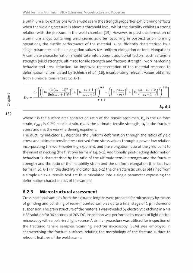
132
Weld Seams in Aluminium Alloy Extrusions: Microstructure and PropertiesC
hap
ter 6
aluminium alloy extrusions with a weld seam the strength properties exhibit minor effects
when the welding pressure is above a threshold level, whilst the ductility exhibits a strong
relation with the pressure in the weld chamber [15]. However, in plastic deformation of
aluminium alloys containing weld seams as often occurring in post-extrusion forming
operations, the ductile performance of the material is insufficiently characterized by a
single parameter, such as elongation values (i.e. uniform elongation or total elongation).
A complete characterization should take into account additional factors, such as tensile
strength (yield strength, ultimate tensile strength and fracture strength), work hardening
behavior and area reduction. An improved representation of the material response to
deformation is formulated by Schleich et al. [16], incorporating relevant values obtained
from a uniaxial tensile test, Eq. 6-1:
Eq. 6-1
where r is the surface area contraction ratio of the tensile specimen, εu is the uniform
strain, εσ0.2 is 0.2% plastic strain, σm is the ultimate tensile strength, σf is the fracture
stress and n is the work-hardening exponent.
The ductility indicator Dv describes the uniform deformation through the ratios of yield
stress and ultimate tensile stress derived from stress values through a power-law relation
incorporating the work-hardening exponent, and the elongation ratio of the yield point to
the onset of necking (the first two terms in Eq. 6-1). Additionally, post-necking deformation
behaviour is characterised by the ratio of the ultimate tensile strength and the fracture
strength and the ratio of the instability strain and the uniform elongation (the last two
terms in Eq. 6-1). In the ductility indicator (Eq. 6-1) the characteristic values obtained from
a simple uniaxial tensile test are thus calculated into a single parameter expressing the
deformation characteristics of the sample.
6.2.3 Microstructural assessmentCross-sectional samples from the extruded lengths were prepared for microscopy by means
of grinding and polishing of resin-mounted samples up to a final stage of 1 μm diamond
suspension. The grain structure of the materials was revealed by electrolytic etching in a 4%
HBF solution for 30 seconds at 20V DC. Inspection was performed by means of light optical
microscopy with a polarised light source. A similar procedure was utilised for inspection of
the fractured tensile samples. Scanning electron microscopy (SEM) was employed in
characterising the fracture surfaces, relating the morphology of the fracture surface to
relevant features of the weld seams.
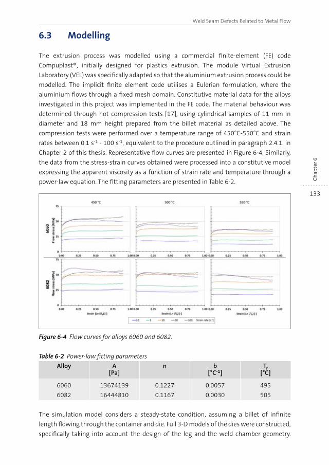
133
Weld Seam Defects Related to Metal Flow
Ch
apte
r 6
6.3 Modelling
The extrusion process was modelled using a commercial finite-element (FE) code
Compuplast®, initially designed for plastics extrusion. The module Virtual Extrusion
Laboratory (VEL) was specifically adapted so that the aluminium extrusion process could be
modelled. The implicit finite element code utilises a Eulerian formulation, where the
aluminium flows through a fixed mesh domain. Constitutive material data for the alloys
investigated in this project was implemented in the FE code. The material behaviour was
determined through hot compression tests [17], using cylindrical samples of 11 mm in
diameter and 18 mm height prepared from the billet material as detailed above. The
compression tests were performed over a temperature range of 450°C-550°C and strain
rates between 0.1 s-1 - 100 s-1, equivalent to the procedure outlined in paragraph 2.4.1. in
Chapter 2 of this thesis. Representative flow curves are presented in Figure 6-4. Similarly,
the data from the stress-strain curves obtained were processed into a constitutive model
expressing the apparent viscosity as a function of strain rate and temperature through a
power-law equation. The fitting parameters are presented in Table 6-2.
Figure 6-4 Flow curves for alloys 6060 and 6082.
Table 6-2 Power-law fitting parameters
Alloy A[Pa]
n b[°C-1]
Tr[°C]
6060 13674139 0.1227 0.0057 495
6082 16444810 0.1167 0.0030 505
The simulation model considers a steady-state condition, assuming a billet of infinite
length flowing through the container and die. Full 3-D models of the dies were constructed,
specifically taking into account the design of the leg and the weld chamber geometry.
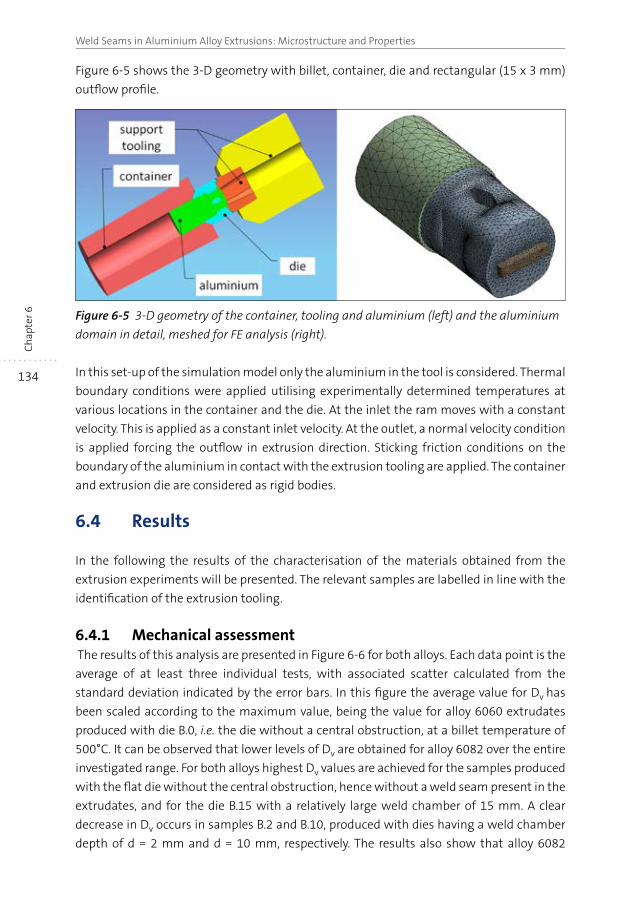
134
Weld Seams in Aluminium Alloy Extrusions: Microstructure and PropertiesC
hap
ter 6
Figure 6-5 shows the 3-D geometry with billet, container, die and rectangular (15 x 3 mm)
outflow profile.
Figure 6-5 3-D geometry of the container, tooling and aluminium (left) and the aluminium
domain in detail, meshed for FE analysis (right).
In this set-up of the simulation model only the aluminium in the tool is considered. Thermal
boundary conditions were applied utilising experimentally determined temperatures at
various locations in the container and the die. At the inlet the ram moves with a constant
velocity. This is applied as a constant inlet velocity. At the outlet, a normal velocity condition
is applied forcing the outflow in extrusion direction. Sticking friction conditions on the
boundary of the aluminium in contact with the extrusion tooling are applied. The container
and extrusion die are considered as rigid bodies.
6.4 Results
In the following the results of the characterisation of the materials obtained from the
extrusion experiments will be presented. The relevant samples are labelled in line with the
identification of the extrusion tooling.
6.4.1 Mechanical assessment The results of this analysis are presented in Figure 6-6 for both alloys. Each data point is the
average of at least three individual tests, with associated scatter calculated from the
standard deviation indicated by the error bars. In this figure the average value for Dv has
been scaled according to the maximum value, being the value for alloy 6060 extrudates
produced with die B.0, i.e. the die without a central obstruction, at a billet temperature of
500°C. It can be observed that lower levels of Dv are obtained for alloy 6082 over the entire
investigated range. For both alloys highest Dv values are achieved for the samples produced
with the flat die without the central obstruction, hence without a weld seam present in the
extrudates, and for the die B.15 with a relatively large weld chamber of 15 mm. A clear
decrease in Dv occurs in samples B.2 and B.10, produced with dies having a weld chamber
depth of d = 2 mm and d = 10 mm, respectively. The results also show that alloy 6082
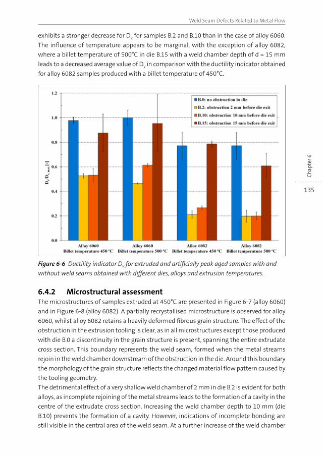
135
Weld Seam Defects Related to Metal Flow
Ch
apte
r 6
exhibits a stronger decrease for Dv for samples B.2 and B.10 than in the case of alloy 6060.
The influence of temperature appears to be marginal, with the exception of alloy 6082,
where a billet temperature of 500°C in die B.15 with a weld chamber depth of d = 15 mm
leads to a decreased average value of Dv in comparison with the ductility indicator obtained
for alloy 6082 samples produced with a billet temperature of 450°C.
Figure 6-6 Ductility indicator Dv for extruded and artificially peak aged samples with and
without weld seams obtained with different dies, alloys and extrusion temperatures.
6.4.2 Microstructural assessmentThe microstructures of samples extruded at 450°C are presented in Figure 6-7 (alloy 6060)
and in Figure 6-8 (alloy 6082). A partially recrystallised microstructure is observed for alloy
6060, whilst alloy 6082 retains a heavily deformed fibrous grain structure. The effect of the
obstruction in the extrusion tooling is clear, as in all microstructures except those produced
with die B.0 a discontinuity in the grain structure is present, spanning the entire extrudate
cross section. This boundary represents the weld seam, formed when the metal streams
rejoin in the weld chamber downstream of the obstruction in the die. Around this boundary
the morphology of the grain structure reflects the changed material flow pattern caused by
the tooling geometry.
The detrimental effect of a very shallow weld chamber of 2 mm in die B.2 is evident for both
alloys, as incomplete rejoining of the metal streams leads to the formation of a cavity in the
centre of the extrudate cross section. Increasing the weld chamber depth to 10 mm (die
B.10) prevents the formation of a cavity. However, indications of incomplete bonding are
still visible in the central area of the weld seam. At a further increase of the weld chamber
136
Weld Seams in Aluminium Alloy Extrusions: Microstructure and PropertiesC
hap
ter 6
depth to d = 15 mm in die B.15, the weld seam becomes less clearly defined, but remains
visible. Similar defect characteristics are observed in samples B.2 and B.10 originating from
the dies with weld chamber depths of 2 mm and 10 mm, respectively produced with a billet
temperature of 500°C.
Results of the inspection of the fracture surfaces by means of scanning electron microscopy
are presented in Figure 6-9. Only the results for alloy 6060 are presented, as the results for
alloy 6082 are of a similar nature. The fracture surface of the material without a weld seam
(die B.0) exhibits a regular ductile fracture morphology without any distinct features related
to material flow in the die. In contrast, the fracture surface of B.2 samples (die welding
chamber depth of 2 mm) clearly show a central longitudinally aligned depression, related
to the cavity caused by non-converging metal streams in the extrusion tooling. Although
no cavity is formed in samples from die B.10 with a welding chamber depth of 10 mm, the
morphology of the fracture surface exhibits a considerable area fraction where no bonding
appears to have occurred. Increasing the welding chamber depth to 15 mm in die B.15 leads
to full bonding in the central region of the extrudate cross section has occurred, indicated
by the finely dimpled fracture surface. Along the edges of the fractured sample the fracture
surface assumes a more linear morphology. Closer examination of the fracture surfaces of
the central area of the B.2 and B.10 samples, presented in Figure 6-10, reveals a distinct
difference: whereas the morphology of the surface of sample B.2 is indicative of a free
extrusion surface where obviously no bonding has occurred, the surface of sample B.10 is
comprised of a fine distribution of small dimples, indicating ductile fracture of a bonded
surface. The elongated shape and shallow appearance of these dimples however suggest a
limited ductile capacity.
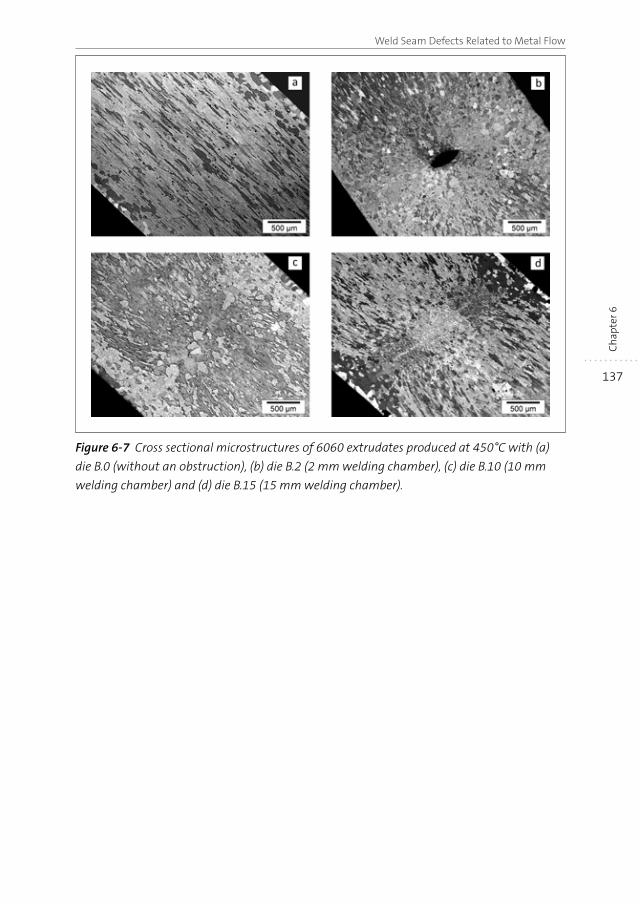
137
Weld Seam Defects Related to Metal Flow
Ch
apte
r 6
Figure 6-7 Cross sectional microstructures of 6060 extrudates produced at 450°C with (a)
die B.0 (without an obstruction), (b) die B.2 (2 mm welding chamber), (c) die B.10 (10 mm
welding chamber) and (d) die B.15 (15 mm welding chamber).
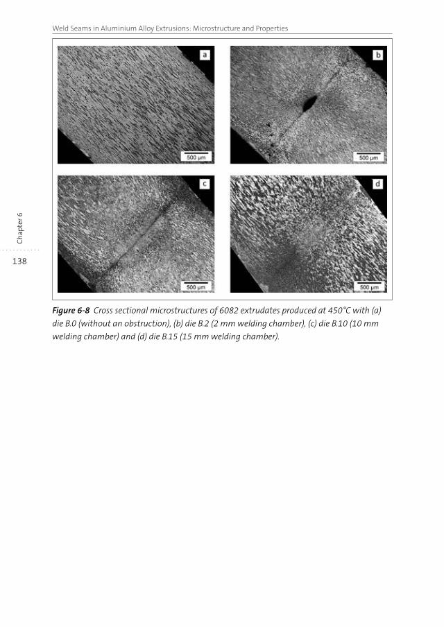
138
Weld Seams in Aluminium Alloy Extrusions: Microstructure and PropertiesC
hap
ter 6
Figure 6-8 Cross sectional microstructures of 6082 extrudates produced at 450°C with (a)
die B.0 (without an obstruction), (b) die B.2 (2 mm welding chamber), (c) die B.10 (10 mm
welding chamber) and (d) die B.15 (15 mm welding chamber).
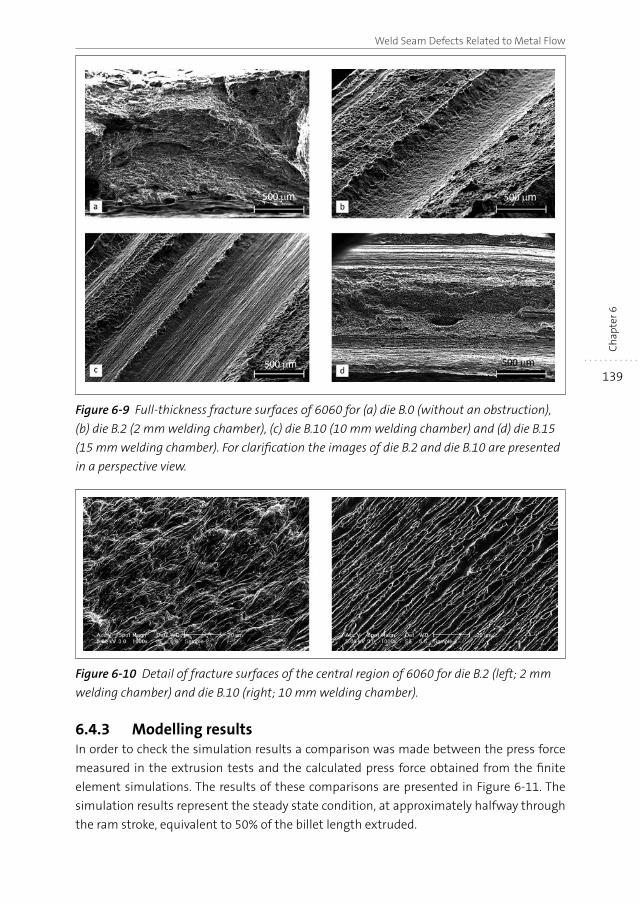
139
Weld Seam Defects Related to Metal Flow
Ch
apte
r 6
Figure 6-9 Full-thickness fracture surfaces of 6060 for (a) die B.0 (without an obstruction),
(b) die B.2 (2 mm welding chamber), (c) die B.10 (10 mm welding chamber) and (d) die B.15
(15 mm welding chamber). For clarification the images of die B.2 and die B.10 are presented
in a perspective view.
Figure 6-10 Detail of fracture surfaces of the central region of 6060 for die B.2 (left; 2 mm
welding chamber) and die B.10 (right; 10 mm welding chamber).
6.4.3 Modelling resultsIn order to check the simulation results a comparison was made between the press force
measured in the extrusion tests and the calculated press force obtained from the finite
element simulations. The results of these comparisons are presented in Figure 6-11. The
simulation results represent the steady state condition, at approximately halfway through
the ram stroke, equivalent to 50% of the billet length extruded.
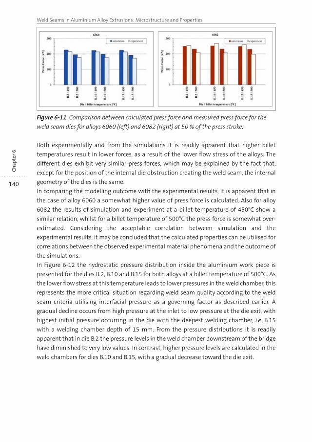
140
Weld Seams in Aluminium Alloy Extrusions: Microstructure and PropertiesC
hap
ter 6
Figure 6-11 Comparison between calculated press force and measured press force for the
weld seam dies for alloys 6060 (left) and 6082 (right) at 50 % of the press stroke.
Both experimentally and from the simulations it is readily apparent that higher billet
temperatures result in lower forces, as a result of the lower flow stress of the alloys. The
different dies exhibit very similar press forces, which may be explained by the fact that,
except for the position of the internal die obstruction creating the weld seam, the internal
geometry of the dies is the same.
In comparing the modelling outcome with the experimental results, it is apparent that in
the case of alloy 6060 a somewhat higher value of press force is calculated. Also for alloy
6082 the results of simulation and experiment at a billet temperature of 450°C show a
similar relation, whilst for a billet temperature of 500°C the press force is somewhat over-
estimated. Considering the acceptable correlation between simulation and the
experimental results, it may be concluded that the calculated properties can be utilised for
correlations between the observed experimental material phenomena and the outcome of
the simulations.
In Figure 6-12 the hydrostatic pressure distribution inside the aluminium work piece is
presented for the dies B.2, B.10 and B.15 for both alloys at a billet temperature of 500°C. As
the lower flow stress at this temperature leads to lower pressures in the weld chamber, this
represents the more critical situation regarding weld seam quality according to the weld
seam criteria utilising interfacial pressure as a governing factor as described earlier. A
gradual decline occurs from high pressure at the inlet to low pressure at the die exit, with
highest initial pressure occurring in the die with the deepest welding chamber, i.e. B.15
with a welding chamber depth of 15 mm. From the pressure distributions it is readily
apparent that in die B.2 the pressure levels in the weld chamber downstream of the bridge
have diminished to very low values. In contrast, higher pressure levels are calculated in the
weld chambers for dies B.10 and B.15, with a gradual decrease toward the die exit.
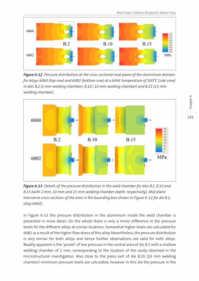
141
Weld Seam Defects Related to Metal Flow
Ch
apte
r 6
Figure 6-12 Pressure distribution at the cross sectional mid-plane of the aluminium domain
for alloys 6060 (top row) and 6082 (bottom row) at a billet temperature of 500°C (side view)
in dies B.2 (2 mm welding chamber); B.10 ( 10 mm welding chamber) and B.15 (15 mm
welding chamber).
Figure 6-13 Details of the pressure distribution in the weld chamber for dies B.2, B.10 and
B.15 (with 2 mm, 10 mm and 15 mm welding chamber depth, respectively). Mid-plane
transverse cross-sections of the area in the bounding box shown in Figure 6-12 for die B.2,
alloy 6060).
In Figure 6-13 the pressure distribution in the aluminium inside the weld chamber is
presented in more detail. On the whole there is only a minor difference in the pressure
levels for the different alloys at similar locations. Somewhat higher levels are calculated for
6082 as a result of the higher flow stress of this alloy. Nevertheless, the pressure distribution
is very similar for both alloys and hence further observations are valid for both alloys.
Readily apparent is the ‘pocket’ of low pressure in the central area of die B.2 with a shallow
welding chamber of 2 mm, corresponding to the location of the cavity observed in the
microstructural investigation. Also close to the press exit of die B.10 (10 mm welding
chamber) minimum pressure levels are calculated, however in this die the pressure in the
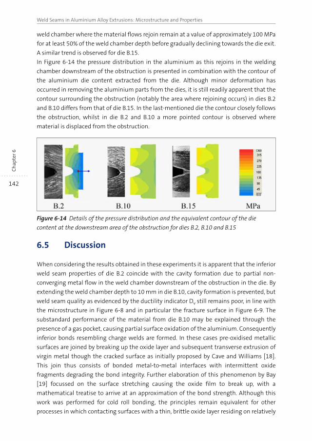
142
Weld Seams in Aluminium Alloy Extrusions: Microstructure and PropertiesC
hap
ter 6
weld chamber where the material flows rejoin remain at a value of approximately 100 MPa
for at least 50% of the weld chamber depth before gradually declining towards the die exit.
A similar trend is observed for die B.15.
In Figure 6-14 the pressure distribution in the aluminium as this rejoins in the welding
chamber downstream of the obstruction is presented in combination with the contour of
the aluminium die content extracted from the die. Although minor deformation has
occurred in removing the aluminium parts from the dies, it is still readily apparent that the
contour surrounding the obstruction (notably the area where rejoining occurs) in dies B.2
and B.10 differs from that of die B.15. In the last-mentioned die the contour closely follows
the obstruction, whilst in die B.2 and B.10 a more pointed contour is observed where
material is displaced from the obstruction.
Figure 6-14 Details of the pressure distribution and the equivalent contour of the die
content at the downstream area of the obstruction for dies B.2, B.10 and B.15
6.5 Discussion
When considering the results obtained in these experiments it is apparent that the inferior
weld seam properties of die B.2 coincide with the cavity formation due to partial non-
converging metal flow in the weld chamber downstream of the obstruction in the die. By
extending the weld chamber depth to 10 mm in die B.10, cavity formation is prevented, but
weld seam quality as evidenced by the ductility indicator Dv still remains poor, in line with
the microstructure in Figure 6-8 and in particular the fracture surface in Figure 6-9. The
substandard performance of the material from die B.10 may be explained through the
presence of a gas pocket, causing partial surface oxidation of the aluminium. Consequently
inferior bonds resembling charge welds are formed. In these cases pre-oxidised metallic
surfaces are joined by breaking up the oxide layer and subsequent transverse extrusion of
virgin metal though the cracked surface as initially proposed by Cave and Williams [18].
This join thus consists of bonded metal-to-metal interfaces with intermittent oxide
fragments degrading the bond integrity. Further elaboration of this phenomenon by Bay
[19] focussed on the surface stretching causing the oxide film to break up, with a
mathematical treatise to arrive at an approximation of the bond strength. Although this
work was performed for cold roll bonding, the principles remain equivalent for other
processes in which contacting surfaces with a thin, brittle oxide layer residing on relatively
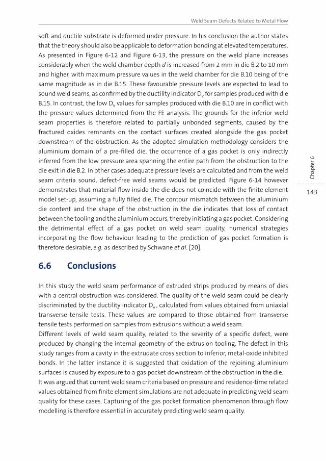
143
Weld Seam Defects Related to Metal Flow
Ch
apte
r 6
soft and ductile substrate is deformed under pressure. In his conclusion the author states
that the theory should also be applicable to deformation bonding at elevated temperatures.
As presented in Figure 6-12 and Figure 6-13, the pressure on the weld plane increases
considerably when the weld chamber depth d is increased from 2 mm in die B.2 to 10 mm
and higher, with maximum pressure values in the weld chamber for die B.10 being of the
same magnitude as in die B.15. These favourable pressure levels are expected to lead to
sound weld seams, as confirmed by the ductility indicator Dv for samples produced with die
B.15. In contrast, the low Dv values for samples produced with die B.10 are in conflict with
the pressure values determined from the FE analysis. The grounds for the inferior weld
seam properties is therefore related to partially unbonded segments, caused by the
fractured oxides remnants on the contact surfaces created alongside the gas pocket
downstream of the obstruction. As the adopted simulation methodology considers the
aluminium domain of a pre-filled die, the occurrence of a gas pocket is only indirectly
inferred from the low pressure area spanning the entire path from the obstruction to the
die exit in die B.2. In other cases adequate pressure levels are calculated and from the weld
seam criteria sound, defect-free weld seams would be predicted. Figure 6-14 however
demonstrates that material flow inside the die does not coincide with the finite element
model set-up, assuming a fully filled die. The contour mismatch between the aluminium
die content and the shape of the obstruction in the die indicates that loss of contact
between the tooling and the aluminium occurs, thereby initiating a gas pocket. Considering
the detrimental effect of a gas pocket on weld seam quality, numerical strategies
incorporating the flow behaviour leading to the prediction of gas pocket formation is
therefore desirable, e.g. as described by Schwane et al. [20].
6.6 Conclusions
In this study the weld seam performance of extruded strips produced by means of dies
with a central obstruction was considered. The quality of the weld seam could be clearly
discriminated by the ductility indicator Dv , calculated from values obtained from uniaxial
transverse tensile tests. These values are compared to those obtained from transverse
tensile tests performed on samples from extrusions without a weld seam.
Different levels of weld seam quality, related to the severity of a specific defect, were
produced by changing the internal geometry of the extrusion tooling. The defect in this
study ranges from a cavity in the extrudate cross section to inferior, metal-oxide inhibited
bonds. In the latter instance it is suggested that oxidation of the rejoining aluminium
surfaces is caused by exposure to a gas pocket downstream of the obstruction in the die.
It was argued that current weld seam criteria based on pressure and residence-time related
values obtained from finite element simulations are not adequate in predicting weld seam
quality for these cases. Capturing of the gas pocket formation phenomenon through flow
modelling is therefore essential in accurately predicting weld seam quality.
144
Weld Seams in Aluminium Alloy Extrusions: Microstructure and PropertiesC
hap
ter 6
6.7 References
[1] F.J. Humphreys, M. Hatherly, Recrystallization and Related Annealing Phenomena,
Elsevier, Oxford, 2004.
[2] W.Z. Misiolek, R.M. Kelly, Fifth International Aluminum Extrusion Technology Seminar,
Aluminium Extruders Council, Chicago, IL, USA, 1992, pp. 315-318.
[3] A.R. Bandar, K. Lorcharoensery, W.Z. Misiolek, J. Mater. Process. Tech., 80-81 (1998),
pp. 657-664.
[4] R. Akeret, Journal of the Institute of Metals, 100 (1972), pp. 202-208.
[5] P.B. Nagy, Journal of Adhesion Science and Technology, 5 (1991), pp. 619-630.
[6] A. Oosterkamp, L.D. Oosterkamp, A. Nordeide, Weld. J., (2004), pp. 255-261.
[7] R. Akeret, Fifth Aluminum Extrusion Seminar, The Aluminum Association, Chicago, IL,
USA, 1992, pp. 319-336.
[8] H. Valberg, T. Loeken, M. Hval, B. Nyhus, C. Thaulow, Int. J. Mater. Prod. Tec., 10 (1995),
pp. 222-267.
[9] P.F. Bariani, S. Bruschi, A. Ghiotti, CIRP Annals - Manufacturing Technology, 55 (2006),
pp. 287-290.
[10] M. Plata, J. Piwnik, Seventh International Aluminum Extrusion Technology Seminar, The
Aluminum Association, Chicago, IL, USA, 2000, pp. 205-211.
[11] L. Donati, L. Tomesani, J. Mater. Process. Tech., 153-154 (2004), pp. 366-373.
[12] E. Ceretti, L. Mazzoni, C. Giardini, Esaform 2009, Springer, University of Twente, The
Netherlands, 2009.
[13] CEN, European Standard EN 573-3: Aluminium and aluminium alloys - Chemical
composition and form of wrought products, Part 3: Chemical composition and form of
products, Brussels, 2013.
[14] N.E. Nanninga, C. White, T. Furu, O. Anderson, R. Dickson, Int. J. Fatigue, 30 (2008),
pp. 1569-1578.
[15] L. Donati, L. Tomesani, Mater. Sci. Forum., 604-605 (2009), pp. 121-131.
[16] R. Schleich, M. Sindel, T. Keith, M. Liewald, MP Materials Testing, 50 (2008), pp. 472-476.
[17] A. Puchert, T. Prüß, Report, 09/208/2Hn, Institut für Umformtechnik und Umform-
maschinen (IFUM), Leibniz Universiät Hannover, 2009.
[18] J.A. Cave, J.D. Williams, Journal of the Institute of Metals, 101 (1973), pp. 203-207.
[19] N. Bay, Metal Construction, 18 (1986), pp. 369-372.
[20] M. Schwane, F. Gagliardi, A. Jäger, N.B. Khalifa, A.E. Tekkaya, Esaform 2013, Trans Tech
Publications, Aveiro, Portugal, 2013, pp. 787-793.
145
Sum
mar
y
Summary
The properties of aluminium alloys, in particular their light weight and excellent formability,
especially at elevated temperatures, make them the material of choice for the production
of a wide and diverse range of semi-fabricated products of constant cross sectional
dimensions via solid state extrusion. Conventional extrusion is a cyclic, thermomechanical
forming process. In each cycle a pre-heated billet is transformed into a hollow or solid
profile with a constant cross-sectional geometry by forcing the material through a die with
an opening corresponding to the required shape. For structural applications the mechanical
integrity of the extrusions and conformity of properties everywhere along the length of the
continuous extrudate is of paramount importance.
As detailed in Chapter 1, internal joins are formed in the extrudates as a result of the cyclic
nature of the extrusion process and the tooling configuration. At the transition zone
between two consecutively processed billets charge welds are formed. In hollow sections
produced with porthole dies, longitudinal weld seams result from the rejoining of metal
streams inside dies used for the production of hollow profiles. In both cases the joins are
the result of solid bonding. In view of the mechanical performance of structural parts, the
properties of these joins should resemble those of the bulk material as closely as possible.
In the case of charge welds, the affected transitory section is commonly removed from the
extruded length and scrapped. Only in case the position, length and severity of the transition
are known accurately, the right amount of material can be scrapped.
Together with many other process determining parameters, the result of extrusion in
general and the properties of the joins depend on the metal flow through the extrusion
tooling. In Chapter 2 the influence of the die geometry on the material flow and the
resultant weld seams is investigated via analysis of the flow pattern of a complex,
asymmetrical double hollow profile. Material flow was characterised by the billet transition,
expressed by the percentage of the profile cross section filled by the new billet material.
Through experiments and FEM simulations it was concluded that the flow behaviour of a
multi-hollow profile largely depends on the size of the ports (keeping the layout of the die
constant), whilst the addition of a sink-in in the die plate had only a marginal effect. The
transition lengths were found to be near-identical for the three die geometries. Conversely,
the transition through the individual ports in the die, each feeding a particular web of the
extrudate, was found to depend on the specific port dimensions. The geometry of the
extruded samples and the location of the weld seams were found to be essentially
independent of the investigated tooling geometries. Simulation proved to be an effective
method to model steady state flow behaviour, although limitations are present when
assuming a fixed, non-history based situation. A full, time-based representation of web
filling requires a transient simulation approach. The transition length could be accurately
described by a simple empirical equation, with a single parameter. Elaboration of this
146
Weld Seams in Aluminium Alloy Extrusions: Microstructure and PropertiesSu
mm
ary
method provides opportunity to predict the billet transition and from thereon optimise the
transition though modification of the intended tooling geometry before actually
manufacturing the die.
Chapter 3 deals with the formation and properties of charge welds. These charge welds
result from the interfacial contact of initially planar and heavily oxidised billet faces. This
interface undergoes significant deformation and follows the material flow pattern inside
the profile cross section. Deformation causes the oxide layer to break up into a distribution
of oxide particles residing on the bond interface, thereby affecting the strength and ductility
of the bond. The strength and ductility of the charge weld interface is a weighted average
of the area fraction of material with the original bulk properties and the area fraction with
low cohesive strength due to the densely populated oxide particle interface originating
from the fractured oxide layer. As a result of this balance, the properties in the transition
area drop to values well below those of the bulk material and subsequently recover up to
nominal levels as the charge weld evolves and the oxide particulates become more widely
dispersed. The concept of a composite material structure bounded by an evolutionary oxide
particle populated interface introduced in this work may be further developed and
implemented in an algorithm aimed at predicting the charge weld performance in relation
to the transition percentage. With this concept, in combination with the empirical equation
describing the charge weld evolution presented in Chapter 2, the properties of the charge
weld at each longitudinal position in the extrudate can be predicted.
In contrast to charge welds, (for hollow extrudates) longitudinal weld seams are present
throughout the entire length. In Chapter 4 the properties of defect-free longitudinal weld
seams are investigated. Depending on alloy composition, material flow and specific, local
conditions inside the tooling, different resultant microstructures can evolve. In conditions
where recrystallisation is supressed, e.g. through the addition of dispersoid-forming
elements or through appropriate processing conditions, a fibrous, heavily deformed grain
morphology forms and the longitudinal weld seam remains at least partially present as a
microstructural feature. In this case deformation during extrusion results in strong
crystallographic textures, with a discontinuity across the weld seam. In other situations,
e.g. in dispersoid-free alloys and appropriate extrusion processing conditions,
recrystallisation occurs during extrusion. Under such conditions the deformed micro-
structure evolves into new equiaxed grains and only short remnants of the weld seam are
still detectable. In case the grains at the weld seam are allowed to evolve further the weld
seam delineation is fully eliminated. The recrystallisation also eliminates most of the
deformation texture components, resulting in far weaker crystallographic orientations
with only minor remaining features related to the longitudinal weld seam. These
microstructural differences are reflected in the mechanical properties as determined by
means of room temperature tensile testing of weld seam-containing samples. In samples
containing unrecrystallised structures strain localisation occurs in the vicinity of the weld
seam. As a result the ductility is reduced in comparison with equivalent material structures
147
Summary
Sum
mar
y
without a central weld seam. However strength properties, such as the ultimate tensile
strength are essentially unaffected by the presence of a weld seam. In contrast, for
recrystallised materials strain remains non-localised close to the point of fracture regardless
of the presence of a weld seam, and as a result both the ductility and the tensile strength
are unaffected by the presence of the weld seam.
Chapter 5 focusses on the processes leading to failure of the longitudinal weld seams. To
this aim X-ray computer tomography was performed on tensile samples where loading
was halted just prior to fracture, i.e. at strains exceeding 90% of the fracture elongation.
The results showed that dispersoid-free material capable to recrystallise during extrusion
exhibits no significant damage localisation around the weld seam area. Even for post-
extrusion heat treatment conditions leading to a markedly different fracture mechanism,
properties were shown to be insensitive to the presence of a weld seam. For the as-extruded
condition with an equiaxed grain structure there is no preferred damage path, and fracture
proceeds via a mixed intergranular and transgranular fracture mode, irrespective of the
grain orientation. In the peak-aged state the damage evolution is intergranular and the
fracture path follows those grain boundaries most susceptible to the resolved stress
orientation, irrespective of their location with regard to the weld seam. In the dispersoid-
rich material recystallisation is suppressed, leading to a refined structure of elongated
clusters of small (sub-)grains separated by both low and high-angle grain boundaries,
partially within the confines of the original deformed grains. This structure forms regardless
of the applied processing conditions. In the as-extruded condition the refined structure and
particle distribution leads to an overly transgranular fracture mode due to the widespread
presence of damage initiation sites throughout the fine grained microstructure. Similarly,
in the artificially aged condition the finely distributed precipitate distribution promotes a
transgranular fracture mode. Hence there was no change in damage evolution and
associated fracture behaviour. However in this alloy microstructure there is a clear influence
of the presence of a weld seam having a distinct damage-initiating effect. This is ascribed
to the pronounced crystallographic deformation texture originating from the material flow
during extrusion as detailed in the foregoing chapter.
In Chapter 6 the influence of macro-defects due to non-ideal tooling geometry on the
properties of longitudinal weld seams is investigated. One of the determining geometrical
factors is the longitudinal position of the mandrel supports relative to the die outflow, as
demonstrated in experiments with model dies with a single obstruction located at different
positions relative to the die outflow channel. The ductility indicator Dv, calculated from
values obtained from uniaxial transverse tensile tests was found to be an effective method
to characterise the weld seam performance of these materials. These values were compared
to those obtained from extrusions with an identical geometry, but without the presence of
a weld seam. At a large distance between the mandrel support and the die outflow defect-
free weld seams are obtained. At shorter distances defects occur, with associated reductions
in the values of the ductility indicator. The defects in this study range from a cavity in the
148
Weld Seams in Aluminium Alloy Extrusions: Microstructure and PropertiesSu
mm
ary
extrudate cross section to a sub-standard, metal-oxide inhibited bond. In the latter instance
it is suggested that oxidation of the rejoining aluminium surfaces is caused by exposure to
an internal gas pocket downstream of the mandrel support in the die. The observed
phenomena correlate well with the pressure contours obtained from the simulations. Low
contact pressure is a clear indication of insufficient or no contact on the bond plane.
Satisfactory bond quality occurs when the contact pressure exceeds the local material flow
stress. It is argued that current weld seam criteria based on the combination of pressure
and residence-time related values obtained from finite element simulations are not
adequate in predicting weld seam quality for these cases. Capturing of the gas pocket
formation phenomenon downstream of the mandrel supports through flow modelling is
therefore essential in accurately predicting weld seam quality.
In general, from this work it can be concluded that due to the nature of the pre-oxidised
bond surfaces, properties of charge welds are always inferior to the base metal properties
and transition lengths should always be removed in extrusions for structural applications.
The evolution of the charge weld length can be adequately characterised by a simple
equation with a single free parameter. Elaboration of this method can lead to a prediction
of the charge weld transition length and from thereon optimisation of the transition length
through modification of the die geometry.
In longitudinal weld seams the occurrence of flow related defects adversely affects the
properties of longitudinal weld seams. These flow related phenomena can be captured by
means of simulation, focussing on pressure acting on the bond plane in the weld chamber
and thus prediction of the longitudinal weld seams quality. In the absence of the above
mentioned defects the properties of longitudinal weld seams are dependent on the
evolutionary microstructure, dictated by the alloy composition and the process parameters.
In recrystallised microstructures the mechanical properties are essentially insensitive to
the presence of a longitudinal weld seam, due to the randomly oriented grain structure and
associated damage mechanisms.
In defect-free weld seams formed in non-recrystallised structures the presence of a weld
seam has a clear effect on the ductility properties. This influence is ascribed to complex,
mirrored crystallographic textures, inherent to the deformation process operating in
extrusion. In view of the latter it is unrealistic to expect longitudinal weld seams to achieve
identical properties in comparison with the bulk, non-weld seam containing material.
149
Sam
enva
ttin
g
Samenvatting
Door de bijzondere eigenschappen van aluminium, in het bijzonder de uitstekende warm-
omvormbaarheid en de lage dichtheid, wordt het materiaal veelvuldig middels extrusie
verwerkt tot een breed scala aan halffabrikaten met een constante dwarsdoorsnede. Het
conventionele extrusieproces is een cyclisch, thermomechanisch omvormproces. In een
extrusiecyclus wordt een voorverwarmd blok aluminium, de billet, omgevormd tot een
langwerpig product met een constante dwarsdoorsnede. Hiertoe wordt het werkstuk door
één of meer openingen in een matrijs corresponderend met de gewenste profielvorm
geperst. In de uiteindelijke constructieve toepassingen is het mechanisch gedrag van de
geëxtru deerde halffabrikaten van doorslaggevend belang. Hierbij dienen de mechanische
eigenschappen over de gehele lengte van het profiel te voldoen aan de minimaal vereiste
waarden.
Zoals toegelicht in Hoofdstuk 1 ontstaan er bij extrusie altijd in het profiel geïntegreerde
verbindingen. Deze verbindingen zijn inherent aan het cyclische karakter van het extrusie-
proces en de toegepaste gereedschapsvormen. In het overgangsgebied tussen twee
opeenvolgende geperste billets ontstaat er per definitie een blokovergang. Deze overgang
kenmerkt zich door dwarsnaden die de verbinding vormen tussen het materiaal afkomstig
van het oude en het nieuwe billetmateriaal. In holle profielen die met behulp van porthole
matrijzen worden geproduceerd ontstaan eveneens langsnaden ten gevolge van het
recombineren van de individuele materiaalstromen in de matrijs. In beide gevallen vormt
zich een verbinding zonder dat er sprake is van een smeltproces, oftewel de verbinding
komt tot stand door ‘solid-bonding’. Met betrekking tot de mechanische eigenschappen is
het wenselijk dat de eigenschappen van deze verbindingen zo veel mogelijk overeenkomen
met de bulk-eigenschappen elders in de profieldoorsnede. In het geval van dwarsnaden
wordt normaliter het betreffende gedeelte met de blokovergang uit de geëxtrudeerde
lengte verwijderd en verschroot. Het elimineren van het juiste gedeelte van het materiaal
vereist dan een goede definitie van de blokovergang, waarbij zowel de positie als het
verloop van de eigenschappen dienen nauwkeurig bekend dienen te zijn.
Het extrusieresultaat in het algemeen en de eigenschappen van de extrusienaden in het
bijzonder zijn onder andere afhankelijk van de materiaalstroming door het extrusie-
gereedschap. In Hoofdstuk 2 wordt het onderzoek naar de invloed van de matrijsgeometrie
op de materiaalstroming en de vorming van extrusienaden beschreven. In dit onderzoek
wordt het stromingspatroon van een complex, asymmetrisch meergatsprofiel geanalyseerd.
De materiaalstroming door drie verschillende matrijs uitvoeringen is gekarakteriseerd door
het verloop van de blokovergang weer te geven als het percentage van de dwarsdoorsnede
van het profieloppervlak welke gevuld wordt door het materiaal van de nieuwe billet. Op
basis van experimenten en ‘eindige elementen’ simulaties is vastgesteld dat de materiaal-
stroming voornamelijk wordt bepaald door de afmetingen van de poorten in de matrijs (bij
150
Weld Seams in Aluminium Alloy Extrusions: Microstructure and PropertiesSa
men
vatt
ing
een verder ongewijzigde globale matrijsgeometrie). De toevoeging van een voorkamer
(‘sink-in’) in de matrijsplaat bleek slechts een minimale invloed te hebben. Het verloop van
de totale blokovergang blijkt voor de drie onderzochte matrijsgeometrieën vrijwel identiek
te zijn. Echter, de stroming door de individuele matrijspoorten die elk een specifiek deel van
de profieldoorsnede vullen, wordt sterk beïnvloed door de afmeting van de poorten. De
onderzochte variaties op de matrijsgeometrie bleken geen invloed te hebben op de
maatvoering van het profiel en de positie van de langsnaden. Middels simulatie bleek het
‘steady-state’ stromingsgedrag efficiënt gemodelleerd te kunnen worden, echter met
beperkingen ten gevolge van de aanname van een instantane situatie waarbij de
stromingshistorie als constant werd beschouwd. Om de historie-effecten optredend bij het
vullen van de profieldoorsnedes door het nieuwe billetmateriaal te kunnen modelleren is
een dynamisch stromingsmodel vereist.
Het verloop van de blokovergang kon nauwkeurig beschreven worden door een eenvoudige
empirische vergelijking met slechts één parameter. Nader uitwerken van deze methodiek
biedt de mogelijkheid om de blokovergang te voorspellen en van daaruit de omvang van de
blokovergang te optimaliseren door het aanpassen van het matrijsontwerp, vooruitlopend
op de werkelijke fabricage van het persgereedschap.
In Hoofdstuk 3 worden de vorming en de navenante eigenschappen van dwarsnaden
behandeld. Dwarsnaden ontstaan als gevolg van het contact tussen de oorspronkelijk
vlakke, sterk geoxideerde oppervlakken van de kopse kanten van twee opeenvolgende
geëxtrudeerde billets. Ten gevolge van de plastische deformatie tijdens extrusie wordt het
contactoppervlak sterk vervormd wanneer dit het stromingspatroon in het dwarsoppervlak
van het profiel volgt. Als gevolg van de deformatie zal de oxidelaag fragmenteren. Door de
aanwezigheid van de gefragmenteerde oxidedeeltjes op het contactvlak zal de sterkte en
de ductiliteit van de gevormde verbinding lager zijn dan de bulk-eigenschappen. De
eigenschappen van de totale dwarsnaad zijn af te leiden uit de verhouding tussen de
oppervlaktes van het ‘schone’ bulk-materiaal en die van het materiaal met een lage sterkte
ten gevolge van de oxidedeeltjes op het grensvlak. Als gevolg hiervan treedt er een sterke
initiële afname van de eigenschappen in de blokovergang op, gevolgd door een geleidelijk
herstel van de eigenschappen naarmate de blokovergang evolueert en de oxidedeeltjes
over een groter oppervlak verdeeld worden. Met een nadere uitwerking van het model van
een samengestelde structuur gescheiden door een grensvlak met variërende eigenschappen
ten gevolge van de verdeling van oxidedeeltjes kunnen de eigenschappen van de dwarsnaad
berekend worden. In combinatie met de in Hoofdstuk 2 beschreven methodiek om het
verloop van de blokovergang te berekenen kan het model vervolgens geïmplementeerd
worden in een algoritme waarbij de eigenschappen van de dwarsnaden als functie van de
longitudinale positie in de blokovergang voorspeld kunnen worden.
In tegenstelling tot dwarsnaden zijn langsnaden aanwezig over de gehele lengte van het
geëxtrudeerde profiel. In Hoofdstuk 4 zijn de eigenschappen van ‘goede’ langsnaden zonder
defecten onderzocht. De hierbij gevormde microstructuur is afhankelijk van de legerings-
151
Samenvatting
Sam
enva
ttin
g
samenstelling, de procescondities en de locale specifieke omstandigheden in de extrusie-
matrijs. In omstandigheden waar rekristallisatie van de microstructuur niet optreedt,
bijvoorbeeld door de aanwezigheid van dispersoïde-vormende elementen in de legering of
door het realiseren van geschikte procesomstandigheden, vormt zich een zwaar
gedeformeerde korrelstructuur waarbij de originele korrels uit de billet tot langgerekte
vezels zijn vervormd. De langsnaad blijft dan gedeeltelijk zichtbaar in de microstructuur.
Onder deze condities ontstaat een kristallografische deformatietextuur. In deze textuur
ontstaat een discontinuïteit als gevolg van het feit dat de textuur-componenten gespiegeld
voorkomen aan weerszijden van de langsnaad. Bij een dispersoïde-vrije legering,
geëxtrudeerd bij passende condities, zal rekristallisatie wèl optreden. In dat geval zal de
gedeformeerde microstructuur transformeren naar een uniforme korrelstructuur, waarbij
de langsnaad deels nog herkenbaar blijft. Op andere plaatsen evolueert de korrelstructuur
zodanig dat de aanwezigheid van de langsnaad volledig wordt uitgewist door de nieuw
gevormde korrelstructuur. Door het reksritallisatieproces wordt de deformatie textuur
geëlimineerd en ontstaan er veel zwakkere voorkeursoriëntaties. De aanwezigheid van de
langsnaad is hier vrijwel niet merkbaar. De verschillen in microstructuur komen tot uiting
in de mechanische eigenschappen bepaald door middel van uniaxiale trekproeven bij
kamertemperatuur op monsters met een langsnaad. De uitkomsten zijn vergeleken met de
mechanische waarden afkomstig van equivalente monsters zonder een centrale langsnaad.
In de niet-gerekristalliseerde microstructuren is de vervorming in de proefstaaf
geconcentreerd in een locaal gebied rondom de langsnaad. Als gevolg hiervan heeft dit
materiaal een lagere ductiliteit in vergelijking met materiaal zonder de langsnaad maar
met een equivalente microstructuur. De sterkte-eigenschappen, zoals de rekgrens en de
treksterkte worden echter vrijwel niet beïnvloed door de aanwezigheid van een langsnaad.
In tegenstelling tot bovenstaande uitkomsten blijft de rekverdeling in gerekristalliseerde
structuren uniform verdeeld over de proefstaaf tot vlak voor het optreden van breuk,
onafhankelijk van de aanwezigheid van de langsnaad. Als gevolg hiervan is er geen verschil
in zowel de ductiliteit en de sterkte-eigenschappen van materiaal met en zonder een
langsnaad.
In Hoofdstuk 5 worden de processen die uiteindelijk leiden tot falen van langsnaden
onderzocht, gebruik makend van röntgen computer-tomografie (CT) analyses op strips die
uniaxiaal belast zijn tot vlak voor het moment van breuk. Uit deze analyses blijkt dat er in
gerekristalliseerd materiaal er geen significante, gelocaliseerde schade-ontwikkeling
optreedt in de nabijheid van de langsnaad. Hetzelfde resultaat wordt ook verkregen na
warmtebehandeling van het materiaal, ondanks het feit dat er in deze geharde toestand
een totaal ander breukmechanisme optreedt. In dit materiaal met een gerekristalliseerde,
uniforme korrelstructuur is er in de geëxtrudeerde toestand geen voorkeursrichting voor
scheurgroei. Er treedt een gemengd inter- en transkristallijn breukmechanisme op,
onafhankelijk van de korreloriëntatie rondom de langsnaad. Na warmtebehandeling van
dit materiaal verandert het breukgedrag naar een volledig interkristallijn mechanisme.
Hierbij wordt de scheurgroeirichting bepaald door de korrel grenzen die het meest ongunstig
152
Weld Seams in Aluminium Alloy Extrusions: Microstructure and PropertiesSa
men
vatt
ing
georiënteerd zijn ten opzichte van de spanningsrichting, onafhankelijk van de locatie van
de korrels ten opzicht van de langsnaad.
Zoals eerder geconstateerd treedt er in het materiaal met een hoge concentratie aan
dispersoïden geen rekristallisatie op. Dit resulteert in een vezelstructuur als gevolg van de
deformatie van de originele korrelstructuur van de gegoten billets. In deze langgerekte
korrels is een subkorrelstructuur ontstaan. De korrels worden gescheiden door de originele
korrelgrenzen overblijvend van de korrels uit de oorspronkelijke billet en sub-korrelgrenzen
tussen de subkorrels ingesloten in de originele gedeformeerde korrels. Deze structuur
vormt zich onafhankelijk van de gekozen procesinstellingen. Als gevolg van de verfijnde
microstructuur en de ruime aanwezigheid van dispersoïde deeltjes vindt er op brede schaal
schade-initatie plaats en verloopt scheurgroei voornamelijk transkristallijn. Ook in de
kunstmatige verouderde toestand treedt voornamelijk transkristallijne scheurgroei op,
mede door de precipitaatverdeling als gevolg van de warmtebehandeling. Het schade-
mechanisme en het breukgedrag blijven in dit geval dan ook ongewijzigd. Een belangrijk
verschil is echter de invloed van de langsnaad, die voor dergelijk materiaal wel een duidelijk
schade-initiërend effect heeft, hetgeen toegeschreven wordt aan de specifieke kristallo-
grafische textuur, zoals beschreven in het voorgaande hoofdstuk.
Het onderzoek beschreven in Hoodstuk 6 richt zich op de macroscopisch waarneembare
defecten gerelateerd aan de geometrie van het extruisiegereedschap. Een belangrijk
kenmerk is de longitudinale positie van de verbindingsbruggen waarmee de matrijskern in
het perskanaal wordt verankerd. Deze afhankelijkheid is onderzocht in geëxtrudeerde
strips afkomstig uit testmatrijzen waarin een obstructie op verschillende afstanden ten
opzichte van de uitstroomopening wordt gepositioneerd. De eigenschappen van de
gevormde langsnaden in de onderzochte materialen bleken goed gekarakteriseerd te
kunnen worden door de ductiliteitsindicator Dv . Deze grootheid wordt afgeleid uit de
resultaten van uniaxiale transversale trekproeven uitgevoerd bij kamertemperatuur. De
verkregen waarden zijn vergeleken met resultaten behaald uit beproevingen van materialen
geproduceerd met dezelfde matrijsvorm, echter zonder een centrale obstructie en dus
zonder langsnaad. Een grote afstand tussen de obstructie en de uitstroomopening
resulteert in welnaden zonder defecten. Bij kleiner wordende afstanden ontstaan defecten,
met een daarbij gepaard gaande afname in de waarden voor de ductiliteitsindicator. De in
deze studie gegenereerde defecten lopen uiteen van een niet-volledige metallische
verbinding ten gevolge van een oxidefilm op het contactvlak van de langsnaad tot het
ontstaan van een centrale holte in de profieldoorsnede. In het eerste geval is het aannemelijk
gemaakt dat oxidatie van de aluminium contactvlakken is veroorzaakt door blootstelling
aan lucht aanwezig in een interne holte achter de obstructie in de matrijs. Deze holte
ontstaat door het niet-volledig samenvloeien van de materiaalstromen na het passeren
van de obstructie. De experimentele resutaten komen goed overeen met drukverdelingen
berekend met behulp van ‘eindige elementen’ simulaties. Een lage contactdruk is dan een
duidelijke indicatie van een onvoldoende of een zelfs afwezig contact tussen de materiaal-
stromen. Een langsnaad met voldoende eigenschappen ontstaat vanaf het moment dat de
153
Samenvatting
Sam
enva
ttin
g
contactdruk de locale vloeispanning van het aluminium overschrijdt. Op basis van de
behaalde resultaten wordt beargumenteerd dat de gangbare criteria voor de eigenschappen
van langsnaden die gebaseerd zijn op druk en verblijftijd niet voldoende geschikt zijn om de
eigenschappen van langsnaden te voorspellen. Een goede voorspelling van de eigenschappen
van langsnaden in relatie tot het optreden van defecten berust dan voornamelijk op een
juiste analyse van de materiaalstroming in de matrijs en de hieraan gekoppelde vorming
van holtes na de verbindingsbruggen.
Uit de analyse van de resultaten van alle in dit project uitgevoerde deelonderzoeken kan
geconcludeerd worden dat de geoxideerde contactoppervlakken van de dwarsnaden in het
gebied van de blokovergang altijd zullen resulteren in materiaal met slechtere eigen-
schappen dan het basismateriaal. Voor constructieve toepassingen moeten deze profiel-
segmenten daarom altijd verwijderd worden. Er is aangetoond dat het verloop van de
blokovergang goed beschreven kan worden met een eenvoudige empirische formule met
slechts één vrije parameter. Een voorspelling van de blokovergang is mogelijk door een
nadere uitwerking van deze methodiek, waarmee vervolgens de lengte van de blokovergang
geoptimaliseerd kan worden door aanpassing van de matrijsgeometrie.
Onvoldoende eigenschappen van langnaden worden veroorzaakt door defecten die
gerelateerd zijn aan de stroming van het aluminium in de extrusiematrijs. De optredende
effecten kunnen met behulp van simulaties geanalyseerd worden, met als belangrijke
voorspellende grootheid parameter de verouding tussen de vloeispanning van het materiaal
en de contactdruk tussen de metaalstromen bij het recombineren in de laskamer van de
extrusiematrijs. Indien er geen defecten optreden zoals hierboven beschreven worden de
eigenschappen van langsnaden bepaald door de microstructuur die ontstaat tijdens
extrusie. Belangrijke grootheden zijn hierbij de legeringssamenstelling en de proces-
parameters. Voor extrusies met een gerekristalliseerde microstructuren ontstaat een
uniforme, richtingsonafhankelijke korrelstructuur met een hieraan gekoppelde willekeurige
verdeling van de optredende schademechanismen. Hierdoor is er vrijwel geen invloed van
een langsnaad op de mechanische eigenschappen. In defect-loze langsnaden in niet-
gerekristalliseerde materialen is er een duidelijke negatieve invloed van de aanwezigheid
van een langsnaad op de ductiliteit van het materiaal. Deze reductie wordt toegeschreven
aan complexe, gespiegelde kristallografische texturen die inherent zijn aan het
deformatieproces tijdens extrusie. Om deze reden is het niet realistisch om er van uit te
gaan dat het voor een niet-rekristalliserende legering mogelijk zal zijn dezelfde mecha-
nische eigenschappen te behalen in producten met en zonder een langsnaad.

155
List
of p
ubl
icat
ion
s
List of publications
First author[1] A.J. Den Bakker, W.H. Sillekens, E. Meijers, Experimental study of longitudinal weld-seam
properties in hollow EN AW-6060 and EN AW-6082 aluminium alloy extrusions, Aluminium
Two Thousand, Interall, Florence, 2007.
[2] A.J. Den Bakker, W.H. Sillekens, R.J. Werkhoven, Experimental Study of Weld-Seams in
Hollow EN-AW 6060 and EN-AW 6082 Tubular Aluminium Alloy Extrusions, in: L. Tomesani,
L. Donati (Eds.) Latest Advances In Extrusion Technology and Simulation In Europe and 2nd
Extrusion Benchmark Aracne, Bologna, Italy, 2007.
[3] A.J. Den Bakker, S.P. Edwards, L. ‘t Hoen-Verlterop, R. Ubels, Static and Dynamic Mechanical
Properties of Longitudinal Weld Seams in Industrial AA6060, AA6082 and AA7020
Aluminum Extrusions, Ninth International Aluminum Extrusion Technology Seminar, The
Aluminum Association, Orlando, FL, USA, 2008.
[4] A.J. Den Bakker, S.P. Edwards, J. Zhou, Solid-State Bonding in Longitudinal Weld Seam
Formation, Ninth International Aluminum Extrusion Technology Seminar, Omnipress,
Orlando, FL, USA, 2008.
[5] A.J. Den Bakker, W.H. Sillekens, R.J. Werkhoven, Experimental Study of Longitudinal Weld-
Seam Properties in Tubular AA6060 and AA6082 Extrusions, Ninth International Aluminum
Extrusion Technology Seminar, Omnipress, Orlando, FL, USA, 2008.
[6] A.J. Den Bakker, The role of pressure in weld seam formation, Literature review, Delft
University of Technology, Delft, 2009, pp. 1- 20.
[7] A.J. Den Bakker, R.J. Werkhoven, W.H. Sillekens, L. Katgerman, Towards predictive control
of extrusion weld seams: an integrated approach, Extrusion Workshop 2009 and 3rd
Extrusion Benchmark Dortmund, Germany, 2009, pp. 9-17
[8] A.J. Den Bakker, X. Ma, R.J. Werkhoven, M.B. De Rooij, Surface Pick-up Formation: New
Limits in the Limit Diagram, Tenth International Aluminum Extrusion Technology Seminar,
ET’12, ET Foundation, Miami, FL, USA, 2012, pp. 451-459.
[9] A.J. Den Bakker, R.J. Werkhoven, Metal Flow Analysis in a Complex Die, Tenth International
Aluminum Extrusion Technology Seminar, ET’12, ET Foundation, Miami, FL, USA, 2012,
pp. 571-581.
[10] A.J. Den Bakker, R.J. Werkhoven, R. Van der Nolle, Influence of Die Geometry on Charge
Weld Evolution, in: E. Tekkaya, A. Jäger (Eds.) ICEB 2013-International Conference on
Extrusion and Benchmark, Dortmund, Germany, 2013, pp. 57-64.
[11] A.J. Den Bakker, R.J. Werkhoven, W.H. Sillekens, L. Katgerman, The Origin of Weld Seam
Defects Related to Metal Flow in the Hot Extrusion of Aluminium Alloys EN AW-6060 and
EN AW-6082 J. Mater. Process. Tech., 214 (2014), pp. 2349-2358.
[12] A.J. Den Bakker, X. Ma, L. Katgerman, S. v.d. Zwaag, Microstructural and X-ray
tomographic analysis of damage in extruded aluminium weld seams Mater. Sci. Tech. Ser.,
31 (2015), pp. 94-104.
156
Weld Seams in Aluminium Alloy Extrusions: Microstructure and PropertiesLi
st o
f pu
blic
atio
ns
[13] A.J. Den Bakker, L. Katgerman, S. v.d. Zwaag, Analysis of the structure and resulting
mechanical properties of aluminium extrusions containing a charge weld interface J. Mater.
Process. Tech., 229 (2016), pp. 9-21.
[14] A.J. Den Bakker, X. Wu, L. Katgerman, S. v.d. Zwaag, Microstructure Effects on Damage
Evolution in Aluminum Weld Seams Studied through X-ray Computer Tomography, Eleventh
International Aluminum Extrusion Technology Seminar, ET ‘16, ET Foundation, Chicago, IL,
USA, 2016, pp. 181-195.
Co-authored[15] M.A. Den Bakker, A.J. Den Bakker, R. Beenen, A.H. Mulder, F. Eulderink: Subtotal liver
calcification due to epithelioid hemangioendothelioma Pathol. Res. Pract., 194 (1998),
pp. 189-195.
[16] R.T. Shuey, A.J. Den Bakker, in: M. Tiyakioglu (Ed.) Proceedings from Materials Solutions
Conference 2001, Indianapolis, IN, 2001, pp. 189-194.
[17] W.H. Sillekens, J.A.F.M. Schade van Westrum, A.J. Den Bakker, P.J. Vet, Hydrostatic
Extrusion of Magnesium: Process Mechanics and Performance, in: T. Candra, J.M. Torralba,
T. Sakai (Eds.) Thermec 2003: 4th International Conference on Processing and Manufacturing
of Advanced Materials, Trans Tech Publications, Madrid, Leganes, Spain, 2003, pp. 8.
[18] S.P. Edwards, A.J. Den Bakker, J. Zhou, L. Katgerman, Physical Simulation of Longitudinal
Weld Seam Formation in Aluminium Extrusions Mater. Sci. Forum., 519-521 (2006),
pp. 1403-1408.
[19] S.-P. Edwards, A.J. Den Bakker, J.L. Neijenhuis, W.H. Kool, L. Katgerman, The Influence of
the Solid-State Bonding Process on the Mechanical Integrity of Longitudinal Weld Seams
JSME International Journal Series A Solid Mechanics and Material Engineering, 49 (2006),
pp. 63-68.
[20] W.H. Sillekens, A.J. Den Bakker, Extrusion-die design for enhanced weld-seam
performance: literature review Internal report, MA.05004, TNO, 2007
[21] S.E. Kruger, M. Lord, D. Levesque, A.J. Den Bakker, Detection of kissing bonds in extruded
aluminum by laser-ultrasound, in: O.T. Donald, E.C. Dale (Eds.) 34th Annual Review of
Progress in Quantitative Nondestructive Evaluation, AIP, Quebec, 2008, pp. 279-285.
[22] W.H. Sillekens, D. v.d. Linden, A.J. Den Bakker, Weld seam quality of hollow magnesium
alloy extrusions, in: M.O. Pekguleryuz, R.S. Beals, E.A. Nyberg, N.R. Neelameggham (Eds.)
Magnesium Technology 2008, TMS, USA, 2008.
[23] S.P. Edwards, A.J. Den Bakker, J. Zhou, L. Katgerman, Physical Simulation of Longitudinal
Weld Seam Formation During Extrusion to Produce Hollow Aluminum Profiles, Materials
and Manufacturing Processes, 24 (2009), pp. 409-421.
[24] S.P. Edwards, A.J. Den Bakker, J. Zhou, L. Katgerman, Formation of longitudinal weld
seams in hollow aluminum extrusions International Review of Mechanical Engineering, 3
(2009), pp. 588-608.
[25] M.B. De Rooij, X. Ma, A.J. Den Bakker, R.J. Werkhoven, Surface quality prediction in
aluminum extrusion, in: L. Tomesani, L. Donati (Eds.) 2011 International Conference on
Extrusion and Benchmark, ICEB 2011, Bologna, 2012, pp. 27-34.
157
List of publications
List
of p
ubl
icat
ion
s
[26] A. Bahrami, A.J. Den Bakker, A. Miroux, J. Sietsma, Toward a Recrystallised Microstructure
in Extruded AA6005A Alloy, in: B. Sadler (Ed.) Light Metals 2013 (TMS), John Whiley & Sons,
Inc. , 2013, pp. 347-350.
PatentsJ.S. Haakmat, A.J. den Bakker, Utility pole with frangible tube section, EP2400060 (A1),
2011-12-28

159
Ack
now
ledg
emen
ts
Acknowledgements
These are the final words marking the culmination of a doctoral research project performed
as a ‘part-time’ activity next to my regular employment in industry. This combination has
proven to be a lesson in balancing multiple priorities and finding a modus in keeping all
stakeholders satisfied. This was not always an easy task and is a direct cause for the
somewhat extended duration of this project. Nevertheless, this format has proven to be a
valuable exercise in maintaining a scientific approach directed towards an industrially
relevant subject.
A number of people have been instrumental in arriving at a successful conclusion of this
PhD project and they deserve a special mention.
First and foremost, I would like to thank Professor Sybrand van der Zwaag for his support in
the later stages and the ultimate finalisation of my PhD project. Your willingness to take
over the supervision of my doctoral project ‘on the fly’ is very much appreciated. Your
extensive critical reviews, always backed by prompt constructive comments, and keeping
matters ‘flowing’ has been instrumental in realising a successful completion of this project
and the establishment of a solid thesis!
Equally important is the contribution of Professor Laurens Katgerman, who supervised my
work in the first half of this project. Laurens, your support actions in fact covers quite some
time: from your supervision during my industrial placement at the former Alcan Banbury
laboratories in the late 1980’s and then again during this doctoral research project, finalised
in 2016 – a period spanning more than 25 years! Thank you for your support.
Also I wish to thank the other members of my advisory committee: professor Frans Soetens
and Jie Zhou. Your interest in this work and your feedback during our meetings is greatly
appreciated!
Nedal Aluminium is acknowledged for providing the opportunity for this doctoral study
and supporting the associated activities in this project. I hope the scientific learnings of this
research will find their way into the production environment with profitable results. In
particular the involvement John Haakmat is very much appreciated, not only concerning
his assistance in this project but also as a reliable and knowledgeable colleague and friend.
Thom van Veenendaal, now retired: thank you for always sharing your thoughts and
suggestions!
From the early, initial start of this research on weld seams my ex-(TNO-)colleagues and
good friends Wim Sillekens and Robert Werkhoven have been involved, providing invaluable
support and adding the essential touch of humour – a vital prerequisite to our existence
160
Weld Seams in Aluminium Alloy Extrusions: Microstructure and PropertiesA
ckn
owle
dgem
ents
and working in our respective fields. I sincerely hope we can continue our (bi-?) annual
‘business dinners’!
This project was partially executed with the aid of M2i. This support is gratefully
acknowledged, together with persons involved: Albert Konter for arranging many program-
related details and providing a sounding board for modelling related issues and Victoria
Savran for arranging ‘content-related’ items regarding microstructural characterisations. In
the background Oscar Ruigrok, Alice Sosef and Annelies Zwanenburg provided the
administrative support.
Simon-Peter Edwards: your work was the springboard on which this project was initiated.
It was a pleasure working with you!
An important part of the work described in this thesis was performed with test material
produced at the Leibniz Universität in Hannover. With the aid of Marcus Engelhardt, Norbert
Grittner and Christian Klose extrusions tests were performed, resulting well-defined
sample material suitable for further research. I am much indebted for their assistance and
the professional execution of these activities, together with the friendly atmosphere during
our visits.
The tooling for these extrusion experiments was supplied and sponsored by Almax Mori,
which is greatfully acknowledged. In particular the involvement of Tommaso Pinter for his
input and advice regarding tool design was a valuable contribution – thank you!
I would also like to acknowledge the activities of the students which were in some way
involved in this project: Rens van de Nolle of the Hogeschool Utrecht for his involvement in
the characterisation of the billet transition, Marco Carnevali of the University of Bologna in
assisting with the characterisation of longitudinal weld seams and Xinqi Lin of Dortmund
University, together with his supervisor Martin Schwane, working on finite element
simulations of extrusions. Appreciation is also due to Arnold Kolk for his CAD-related efforts
which he performed in parallel to his graduation project at Delft University.
Performing a part-time industrial-oriented doctoral research project leaves little opportunity
for intense interaction with many fellow researchers. The exception is Abbas Bahrami, with
our desks at the university in Delft situated not far from each other. Thank you for your
assistance in various investigations and for sharing your impressive knowledge in
(aluminium) metallurgy! Likewise, acknowledgements are due to Alexis Miroux for sharing
his profound knowledge.
The involvement of Jason Wu, Ranjita Boose and Gert-Jan Mulder of the Aerospace
Engineering Faculty of the TU Delft in connection with the CT-analyses and the in-situ
161
Acknowledgements
Ack
now
ledg
emen
ts
fractography is much appreciated. Similarly the assistance of Kees Kwakernaak of the 3ME
Faculty of the TU Delft in the EBSD characterisation is gratefully acknowledged.
In the same field, the efforts of René de Kloe of EDAX/Ametek regarding additional EBSD-
characterisation together with the ample time dedicated to discuss the results in much
detail, despite your busy schedule, is very much appreciated. Thank you once again!
I am much indebted to Monica Jenster and Joost Leijten of Maximum Koppel for their kind
willingness in spending a much larger than budgeted effort in producing a PhD thesis with
a very professional lay out. Hope to see you again soon on the first tee…
A warm thank you to my brother Michael and sister in law Andrea for providing numerous
temporary escapes from the traffic jams, usually with a very nice meal to boot! Your move
to a new dwelling further from Delft more or less coincides with the finalisation of my PhD
– but I’m sure there will still be numerous new excuses to visit!
Last, but absolutely not least, my heartfelt thanks to my wife Petra and children Duncan
and Shevaun. Especially for putting up with my often apparently senseless babbling about
why aluminium will or will not ‘stick together’ and various related topics in this – sometimes
seemingly everlasting – adventure. Despite the unexpected twist at the end I’m sure that
our little happy universe will always persevere!

163
Cu
rric
ulu
m v
itae
Curriculum vitae
Andrew James Den BakkerNovember 21st, 1963, Vlaardingen, The Netherlands
Education1976-1984 Secondary education (The Netherlands)
1984-1990 Materials Science at the Delft University of Technology (MSc grade)
Professional careerJanuary 1991 - December 1991 (incl.):
Certification engineer, KIWA N.V., Rijswijk, NL.
January 1992 - June 1997
Research and Development Engineer, Boal BV., De Lier, NL.
June 1997 - March 2000
Technology Engineer, SAPA: (formerly Alcoa), Drunen, NL
April 2000 - December 2003
Project Leader, TNO, Eindhoven, NL
January 2004 - October 2016
Manager Research & Development, Nedal Aluminium, Utrecht, NL

“Who could heed the words of Charlie Darwin
Lords of war just profit from decay
And trade the children’s promise for the jingle
The way we trade our hard earned time for pay”
Excerpt from ‘Charlie Darwin’ written by Jeffrey Carl Prystowsky Benjamin Knox Miller,
performed by The Low Anthem


Weld Seam
s in Alum
inium A
lloy Extrusions: Microstructure and Properties | A
ndrew Jam
es den Bakker
ISBN 978-94-028-0329-7