Embed Size (px)
Citation preview
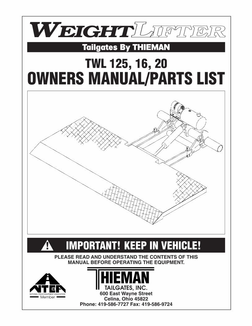
WEIGHTLLIIFFTTEERRTailgates By THIEMAN
TWL 125, 16, 20OWNERS MANUAL/PARTS LIST
IMPORTANT! KEEP IN VEHICLE!!PLEASE READ AND UNDERSTAND THE CONTENTS OF THIS
MANUAL BEFORE OPERATING THE EQUIPMENT.
TAILGATES, INC.600 East Wayne Street
Celina, Ohio 45822Phone: 419-586-7727 Fax: 419-586-9724
HIEMANNATIONAL TRUCK EQUIPMENT ASSOCIATION
Member
TABLE OF CONTENTSPAGE
PARTS ORDERING PROCEDURE .......................................................................2
WARNINGS ...........................................................................................................3
OPERATING INSTRUCTIONS ..............................................................................4
MAINTENANCE GUIDE ........................................................................................5
SEMI-ANNUAL INSPECTION................................................................................6
ELECTRICAL PICTORIALS ..............................................................................6&7
INSPECTION AND LOCATION OF DECALS....................................................7&8
PLATFORM ASM ...................................................................................................8
CONTROL AND CLOSING LINKAGE AND PARTS ..............................................9
TRUNNION, LIFT ARM, AND IDLER ARM ASM..................................................10
PUMP ASM-ELECTRIC CONTROL, GRAVITY DOWN.......................................11
PUMP ASM-ELECTRIC CONTROL, POWER DOWN.........................................12
FOR YOUR RECORDS
Model No. ______________________________ Date Purchased _________________
Serial No. _______________________________________________________________NOTE: When Ordering Parts Be Sure To Include This Information!
PARTS ORDERING PROCEDUREWhen ordering parts, please include all the information asked for below. If this information isnot available, a complete written description or sketch of the required part will help Thiemanidentify and deliver the needed part to you.
THE FOLLOWING INFORMATION MUST BE INCLUDED:
1. Serial Number - Thieman liftgate serial numbers can be found on the tag located on the righthand mounting plate.
2. Model Number and Capacity.3. Platform size and Material - Steel or Aluminum.4. Part number.5. Description.6. Quantity required.
2.
3.
WARNING!
The following list of warnings are to be read before operating the TWL series liftgate.
+ Read this Owner’s Manual and all of the decals on the liftgate BEFORE operating the liftgate.
+ All protective covers and guards must be in place before operating the liftgate.
+ DO NOT operate the liftgate if you do not have a thorough knowledge and understanding ofthe operation of the liftgate.
+ NEVER OVERLOAD THE LIFTGATE. The maximum rated capacity of the TWL series liftgatediffers with each model as follows:
TWL125 6626 - 1250 LBS TWL16 7832 - 1600 LBS TWL20 7832 - 2000 LBSTWL125 7832 - 1250 LBS TWL16 8432 - 1600 LBS TWL20 8432 - 2000 LBSTWL125 8432 - 1250 LBS TWL16 9032 - 1600 LBS TWL20 9032 - 2000 LBS
+ Never use the liftgate if it makes any unusual noises, has vibrations, or fails to operate freely.
+ Make certain that the area below the platform is clear before and at all times during theoperation of the liftgate.
+ Keep hands and feet clear of all pinch points.
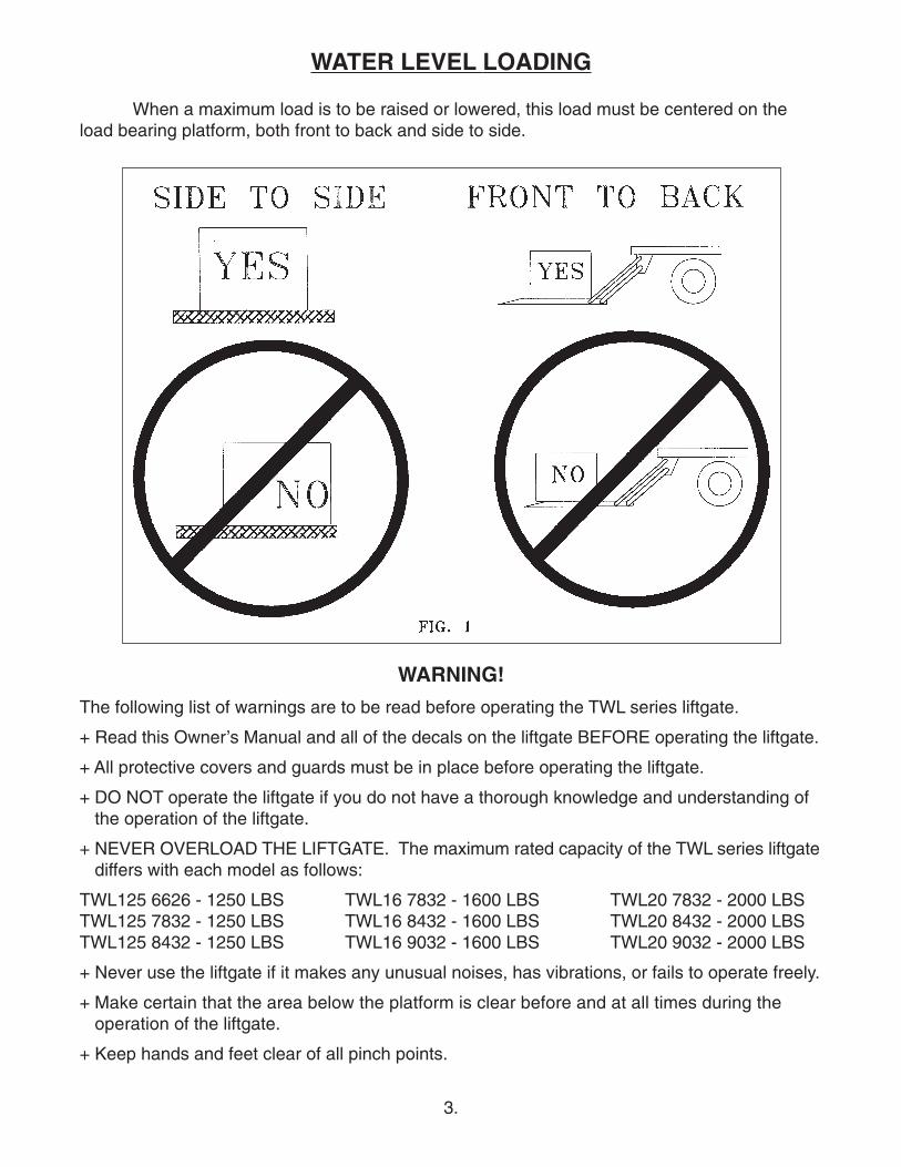
WATER LEVEL LOADING
When a maximum load is to be raised or lowered, this load must be centered on theload bearing platform, both front to back and side to side.
4.
+ The platform must be in the closed position and the transit chains latched properly beforetransit.
+ Always load as close to the center of the platform and as close to the vehicle as possible.See figure 1.
+ Never operate lift trucks on or over any part of the platform.
+ Load and unload the platform from the rear and not from the side of the platform.
+ Only operate Liftgate when vehicle is on level ground and parking brake is set.
+ Follow the maintenance guide as outlined in this manual.
+ DO NOT attempt any repairs unless you are qualified and authorized THIEMAN distributor.
+ If any repairs, adjustments, or maintenance not covered in this manual are required, contactyour nearest Thieman distributor or the factory.
+ DO NOT ride the liftgate, it is not intended as a personnel lift.
+ This liftgate is intended for the use of loading and unloading cargo only, and is not to be usedfor anything other than this.
+ DO NOT modify this liftgate. Altering this liftgate may cause serious personal injury or damagethe liftgate and will void all warranties.
OPERATING INSTRUCTIONSCAUTION:
Be sure to operate liftgate at a safe distance and never improperly load platform as this maycause personal injury or damage to the liftgate.
OPENING OF PLATFORM1. Unhook the stow chains on each side of the platform.2. Raise assembly following step 6 until vertical platform is tight against the rear of the vehicle.3. Lower platform 1/2 way to ground and disengage closing lever by rotating closing handle
counterclockwise until it locks into place before loading platform. Closing lever must be dis-engaged to raise and lower platform in the horizontal position.
LOWERING OF PLATFORM4. Push the lower switch to lower platform to the desired position.
RAISING OF PLATFORM5. Make sure closing lever is disengaged to operate gate with platform in a horizontal position.6. Push the raise switch to raise platform to the desired position.
CLOSING OF PLATFORM7. Lower or raise platform 1/2 way between the ground and the truck bed.8. Engage closing lever by rotating closing handle clockwise until it locks into place. Raise
assembly following step 6 until the platform is vertical.9. Secure platform with the stow chains on both sides of the platform.
5.
MAINTENANCE GUIDEThe following inspection and maintenance operations should be performed at the recommended
intervals or anytime the liftgate shows signs of abuse, and improper or abnormal operation.
MONTHLY INSPECTION AND MAINTENANCEOperate the liftgate throughout its entire operational cycle and check the following:1. Check that there are no unusual noises or vibrations.2. Check platform height relative to bed height. If platform is lower, adjust cylinder with a
13/16 wrench to obtain the necessary height.3. Check for apparent damage to the liftgate such as bent or distorted members, any cracked
welds that may have resulted from overloading or abuse.4. Check for excessive wear in the following areas:
A. Platform hinge pins and lift armsB. All cylinder pins, bolts, and clevisC. Platform extension pivotsD. Linkage pins and clevises
5. Check that the platform pivot pins are in place and retained by their proper retainers.6. Check that all protective covers and guards are properly in place and secured.7. Check for oil leaks in these areas:
A. Lift cylinder.B. Hydraulic hose-replace if it shows signs of wear or cracking.C. Hydraulic fittings-tighten or replace as may be required to stop leakage.
8. Check the oil level in the pump reservoir. With the liftgate in the lowered position the oilshould be within 1/2” from the top of the reservoir. See chart below for oil applications.
9. Check that all wiring and battery cable connections are tight and free of corrosion.10. Lubrication of the TWL series liftgate should be as follows:
Area of Tailgate Type of Lubrication* FrequencyPivot pins w/zerk Grease 50 cyclesPump oil change see chart below yearly*See the parts list for location of the grease zerks.For -40 to 120 F use #0 Grade grease.For -20 to 200 F use #1 Grade grease.
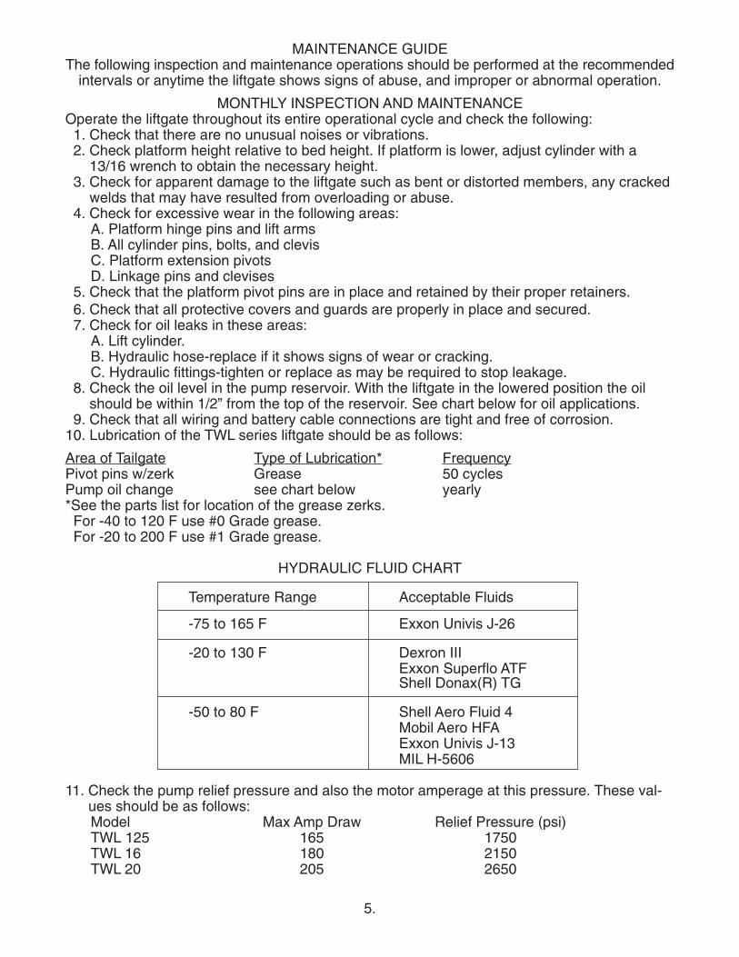
HYDRAULIC FLUID CHART
Temperature Range Acceptable Fluids
-75 to 165 F Exxon Univis J-26
-20 to 130 F Dexron IIIExxon Superflo ATFShell Donax(R) TG
-50 to 80 F Shell Aero Fluid 4Mobil Aero HFAExxon Univis J-13MIL H-5606
11. Check the pump relief pressure and also the motor amperage at this pressure. These val-ues should be as follows:Model Max Amp Draw Relief Pressure (psi)TWL 125 165 1750TWL 16 180 2150TWL 20 205 2650
6.
Semi-Annual Inspection1. Perform the procedures outlined in the Monthly Inspection and Maintenance.2. Inspect pump motor by:
A. Disconnecting battery cable.B. Remove motor end cover.C. Examine the armature brushes for wear. (Brushes should be replaced if they are less
than 1/8” long.)D. Clean all residue out from inside of the motor housing.E. Apply several drops of light weight machine oil to the armature shaft bearing in the motor
end cover and reassemble the motor end cover.3. If the hydraulic oil in the reservoir is dirty:
A. Unfold platform and lower platform to the ground.B. Drain the oil from the hydraulic system and flush the entire system.C. Remove reservoir from pump and clean suction line filter. Also clean out any contami-
nants inside reservoir. Remount reservoir when completed.D. Replace the oil as outlined in Section 9 under Monthly Maintenance and Inspection.
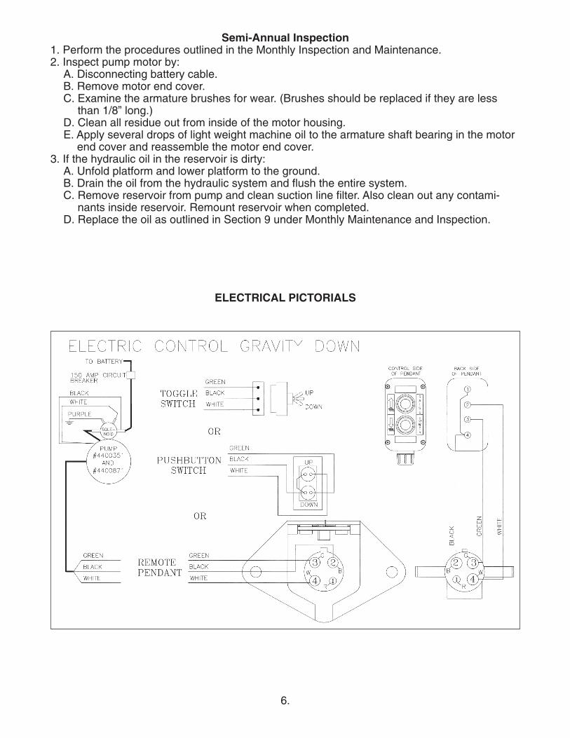
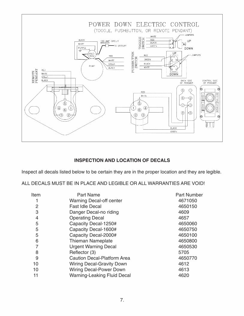
ELECTRICAL PICTORIALS
7.
INSPECTION AND LOCATION OF DECALS
Inspect all decals listed below to be certain they are in the proper location and they are legible.
ALL DECALS MUST BE IN PLACE AND LEGIBLE OR ALL WARRANTIES ARE VOID!
Item Part Name Part Number1 Warning Decal-off center 46710502 Fast Idle Decal 46501503 Danger Decal-no riding 46094 Operating Decal 46575 Capacity Decal-1250# 46500605 Capacity Decal-1600# 46507505 Capacity Decal-2000# 46501006 Thieman Nameplate 46508007 Urgent Warning Decal 46505308 Reflector (3) 57059 Caution Decal-Platform Area 4650770
10 Wiring Decal-Gravity Down 461210 Wiring Decal-Power Down 461311 Warning-Leaking Fluid Decal 4620

8.
PLATFORM ASSEMBLY
Qty/ModelItem Part Number Description
125 16 20
1 3400430 Platform 6626 1 1 11 3400440 Platform 7832 1 1 11 3400450 Platform 8432 1 1 11 3400460 Platform 9032 1 1 11 3400860 Platform - Exp. Metal 7832 1 1 11 3400870 Platform - Exp. Metal 8432 1 1 11 3400880 Platform - Exp. Metal 9032 1 1 12 3103730 Chain Anchor 2 2 23 3103751 Chain and S Hook 2 2 2
9.
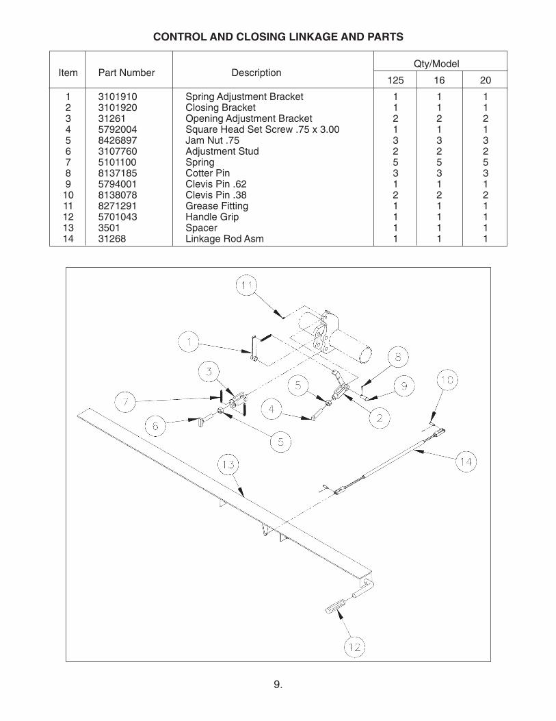
CONTROL AND CLOSING LINKAGE AND PARTS
Qty/ModelItem Part Number Description
125 16 20
1 3101910 Spring Adjustment Bracket 1 1 12 3101920 Closing Bracket 1 1 13 31261 Opening Adjustment Bracket 2 2 24 5792004 Square Head Set Screw .75 x 3.00 1 1 15 8426897 Jam Nut .75 3 3 36 3107760 Adjustment Stud 2 2 27 5101100 Spring 5 5 58 8137185 Cotter Pin 3 3 39 5794001 Clevis Pin .62 1 1 110 8138078 Clevis Pin .38 2 2 211 8271291 Grease Fitting 1 1 112 5701043 Handle Grip 1 1 113 3501 Spacer 1 1 114 31268 Linkage Rod Asm 1 1 1
10.
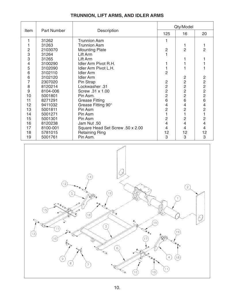
TRUNNION, LIFT ARMS, AND IDLER ARMS
Qty/ModelItem Part Number Description
125 16 20
1 31262 Trunnion Asm 11 31263 Trunnion Asm 1 12 2103070 Mounting Plate 2 2 23 31264 Lift Arm 13 31265 Lift Arm 1 14 3100290 Idler Arm Pivot R.H. 1 1 15 3102090 Idler Arm Pivot L.H. 1 1 16 3102110 Idler Arm 26 3102120 Idler Arm 2 27 2307020 Pin Strap 2 2 28 8120214 Lockwasher .31 2 2 29 8104-006 Screw .31 x 1.00 2 2 210 5001801 Pin Asm. 2 2 211 8271291 Grease Fitting 6 6 612 9411032 Grease Fitting 90° 4 4 413 5001811 Pin Asm 2 2 214 5001271 Pin Asm 1 1 115 5001301 Pin Asm 2 2 216 8120238 Jam Nut .50 4 4 417 8100-001 Square Head Set Screw .50 x 2.00 4 4 418 5781015 Retaining Ring 12 12 1219 5001761 Pin Asm. 3 3 3
11.
Qty/ModelItem Part Number Description
125 16 20
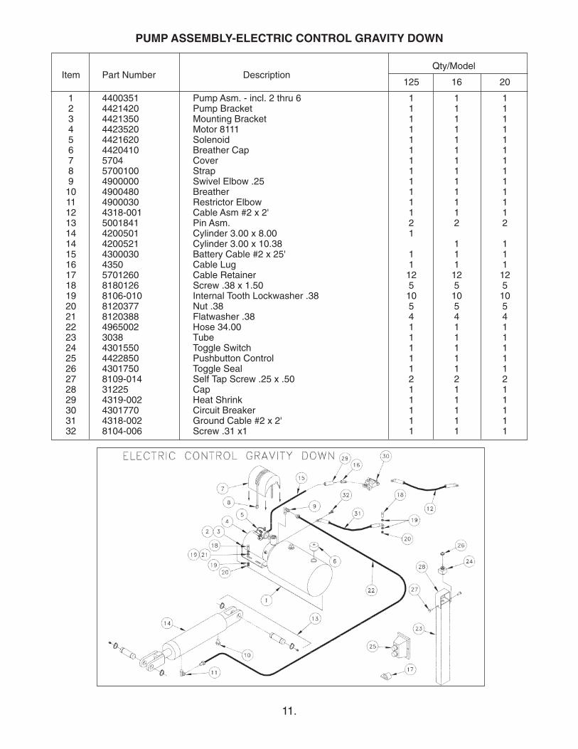
1 4400351 Pump Asm. - incl. 2 thru 6 1 1 12 4421420 Pump Bracket 1 1 13 4421350 Mounting Bracket 1 1 14 4423520 Motor 8111 1 1 15 4421620 Solenoid 1 1 16 4420410 Breather Cap 1 1 17 5704 Cover 1 1 18 5700100 Strap 1 1 19 4900000 Swivel Elbow .25 1 1 110 4900480 Breather 1 1 111 4900030 Restrictor Elbow 1 1 112 4318-001 Cable Asm #2 x 2' 1 1 113 5001841 Pin Asm. 2 2 214 4200501 Cylinder 3.00 x 8.00 114 4200521 Cylinder 3.00 x 10.38 1 115 4300030 Battery Cable #2 x 25' 1 1 116 4350 Cable Lug 1 1 117 5701260 Cable Retainer 12 12 1218 8180126 Screw .38 x 1.50 5 5 519 8106-010 Internal Tooth Lockwasher .38 10 10 1020 8120377 Nut .38 5 5 521 8120388 Flatwasher .38 4 4 422 4965002 Hose 34.00 1 1 123 3038 Tube 1 1 124 4301550 Toggle Switch 1 1 125 4422850 Pushbutton Control 1 1 126 4301750 Toggle Seal 1 1 127 8109-014 Self Tap Screw .25 x .50 2 2 228 31225 Cap 1 1 129 4319-002 Heat Shrink 1 1 130 4301770 Circuit Breaker 1 1 131 4318-002 Ground Cable #2 x 2' 1 1 132 8104-006 Screw .31 x1 1 1 1
PUMP ASSEMBLY-ELECTRIC CONTROL GRAVITY DOWN
12.
Qty/ModelItem Part Number Description
125 16 20
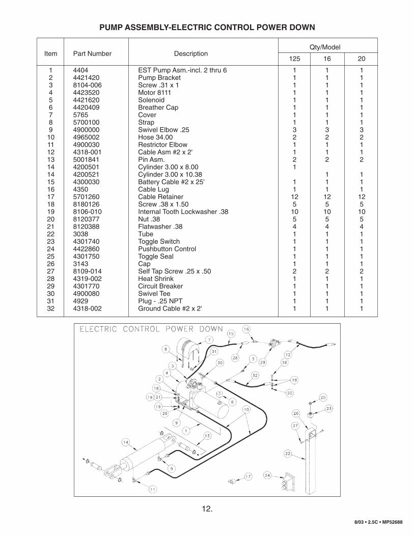
1 4404 EST Pump Asm.-incl. 2 thru 6 1 1 12 4421420 Pump Bracket 1 1 13 8104-006 Screw .31 x 1 1 1 14 4423520 Motor 8111 1 1 15 4421620 Solenoid 1 1 16 4420409 Breather Cap 1 1 17 5765 Cover 1 1 18 5700100 Strap 1 1 19 4900000 Swivel Elbow .25 3 3 310 4965002 Hose 34.00 2 2 211 4900030 Restrictor Elbow 1 1 112 4318-001 Cable Asm #2 x 2' 1 1 113 5001841 Pin Asm. 2 2 214 4200501 Cylinder 3.00 x 8.00 114 4200521 Cylinder 3.00 x 10.38 1 115 4300030 Battery Cable #2 x 25' 1 1 116 4350 Cable Lug 1 1 117 5701260 Cable Retainer 12 12 1218 8180126 Screw .38 x 1.50 5 5 519 8106-010 Internal Tooth Lockwasher .38 10 10 1020 8120377 Nut .38 5 5 521 8120388 Flatwasher .38 4 4 422 3038 Tube 1 1 123 4301740 Toggle Switch 1 1 124 4422860 Pushbutton Control 1 1 125 4301750 Toggle Seal 1 1 126 3143 Cap 1 1 127 8109-014 Self Tap Screw .25 x .50 2 2 228 4319-002 Heat Shrink 1 1 129 4301770 Circuit Breaker 1 1 130 4900080 Swivel Tee 1 1 131 4929 Plug - .25 NPT 1 1 132 4318-002 Ground Cable #2 x 2' 1 1 1
PUMP ASSEMBLY-ELECTRIC CONTROL POWER DOWN
8/03 • 2.5C • MP52688