Embed Size (px)
DESCRIPTION
Nyheder fra Weidmüller 2009/2010
Citation preview

New
s 20
09/2
010
Cat
alo
gu
e
News 2009|2010Catalogue
Order number:1161850000/11/2009/TMMD
www.weidmueller.com
ArgentinaAustraliaAustriaAzerbaijan BahrainBelarusBelgiumBosnia andHerzegovinaBrazilBulgariaCanadaChileChinaColombiaCosta RicaCroatiaCzech RepublicDenmarkEcuadorEgyptEstoniaFinlandFranceGermanyGreat BritainGreeceHong KongHungaryIcelandIndia
IndonesiaIranIrelandIsraelItalyJapanJordanKazakhstanKoreaKuwaitLatviaLebanonLithuaniaLuxembourgMacedoniaMalaysiaMaltaMexicoMoldovaNetherlandsNew ZealandNorwayOmanPakistan PeruPhilippinesPolandPortugalQatarRomaniaRussia
Saudi ArabiaSerbiaSingaporeSlovakiaSloveniaSouth AfricaSpainSwedenSwitzerlandTaiwanThailandTunisiaTurkeyUkraineUnited ArabEmiratesUnited StatesUruguayUzbekistanVenezuelaVietnam
Weidmüller positions itself worldwide successfully on a sustained basis as the leading provider of solutions for electrical connectivity, transmission and conditioning of power, signal and data in industrial environments.
The company develops, produces and sells products in the field of electrical connectivity and electronics.
Weidmüller’s product and service portfolio is dedicated to add value to the products and thereby the business of our customers.

News 2009|2010Electronics
VARITECTOR SPCPluggable surge protection for C&I circuits
Page 8
VARITECTOR SSC 6ANSurge protection fit into a 6 mm width for C&I circuits
Page 10
PRO-MPower supplies for space-saving use in automation technology
Page 2
PLC Front Adaptor (FAD)New Front Adaptors for different PLC Cards
Page 12
ACT20XUniversal, intrinsically safe signal conditioners for hazardous area applications
Page 4
ACT20P BridgeStrain gauge transmitter for reading load cells
Page 6
Power, Signal, Data: For these basic elements of industrial automation, Weidmüller offers a comprehensive system of components being efficiently harmonised.Brought together for specific customer applications, these components lead to integrated solutions for electrical connectivity, transmission and conditioning of power, signals and data.In this way, Weidmüller permanently assures its customers competitive and value advantages with electrical connectivity and electronics. Power, Signal, Data.Weidmüller system of components.Electrical connectivity and electronics with added value.
For detailed information please refer to page 22, 32 and 40 in this catalogue or www.power-signal-data.com!
Photovoltaic junction box Innovative junction box for photovoltaic modules with a rated current of max. 8.5 A
Page 14
CLINICS SOLARThe clever way to optimize the profit of your photovoltaic systems
Page 16
Stringbox with surge protection The custom solution for safety in photovoltaic systems
Page 18
ANNOUNCEMENT
ANNOUNCEMENT
OMNIMATE POWER on BOARDIntegrative connection systems for innovative drive applications
Page 32
OMNIMATE POWER SV / BV 7.62HPCustom-fit high-powered solutions
Page 38
OMNIMATE POWER for IT systemsCustom-fit solutions for special requirements
Page 34
OMNIMATE POWER SL / BL 7.62HPCustom-fit solutions for compact devices
Page 36
OMNIMATE POWER SV / BV 7.62HP HybridCustom-fit solutions for power, signals and EMC
Page 40
OMNIMATE HOUSINGS CH20MIndividual design by combining options of more form, function and appearance
Page 42
Device / PCB
Technical dataThe page references in the footnotes refer to the product information and data in the rear part of the catalogue.
InternetFurther information can be found on the Internet: www.weidmueller.com
FieldPower® – decentralized switched-mode power supplyClose-to-load 24 V power generation and distribution for decentralized DC-systems
Page 24
POCON – Power ConnectorThe compact test-disconnect terminal for current and voltage transformer
Page 20
Fuse-distribution terminal ZSI 2x6/4x2.5Just one terminal for fusing and distributing power
Page 28
PROFINET/AIDA robotics cablingA coherent platform for power, signals and data in automotive body shops
Page 22
PS ZQV test probeHand-free testing with a self-attaching test probe
Page 30
Switching Cabinet / Field
WeiCoS WT 4/4AN/2The established WeiCoS system now also comes with screw connection
Page 26
Electrical Connectivity
Electrical Connectivity

PRO-MPower supplies for space-saving use in automation technology
PRO-M = Power-Reliable-OptimizedThe reliable and optimized power supply for automation technology.
The solid, very narrow metal housing of the 10 different versions of the24 V DC supply enable installation without lateral spacing, thereby savingspace on the DIN rail. AC and DC wide-range inputs and a broadtemperature range allow universal use. Up to 5 modules can be wired in parallel without a diode module in order to flexibly increase the power output. Thanks to its high efficiency, overload resistance and high performance reserves, the PRO-M is the reliable power supply in all applications – and all that in an entry-level product.
The 3-phase PRO-M power supply modules continue to work reliable even if one phase fail, i.e. in two-phase operation.
Thanks to wide-range input (both DC as well as AC voltages
can be used; no switching required) and extensive approvals
(UL/CSA and GL (EMC 1 - bridge)).
International use
Module power can be increased by connecting up
to five power supplies in parallel without diode
module.
Parallel connection
Wide temperature range from
–25 °C … +70 °C.
Robust
Electronics | PRO-M Electronics | PRO-M
Space-saving configuration in the switching
cabinet through very narrow housing
construction and side-by-side connectability.
Narrow
AC / DC
+70 °C to–25 °C
from 33 mm
The right power supply for every application:
1-phase 3 A, 5 A, 7.5 A, 10 A, 20 A, 40 A and
3-phase 5 A, 10 A, 20 A, 40 A.
Wide choice
Rated load
Temperature
120 %
100 %
45 °C 60 °C 70 °C
Power reserve
Powerful
With additional power reserves at standard temperatures.
A.2
Technical data and ordering data can be found beginning on page
2 3

Electronics | ACT20X Electronics | ACT20X
ACT20X-HUI-SAO-LP
The ACT20X family includes digital and analogue signal conditioners for intrinsically
safe circuits: pulse separators, signal isolators, thermal and mA conditioners,
digital and proportional actuator drivers as well as universal signal conditioners.
A variety of functions
Wide ambient temperature
range from –20 °C ... +60 °C.
Robust
+60 °C to–20 °C
No laborious troubleshooting. Alarm function
integrated for cable or sensor errors. In case
of failures, a diagnostic signal is sent to the
control system.
Alarm function
A.8
Technical data and ordering data can be found beginning on page
A universal signal conditioner with a loop-powered output and a width of only 12.5 mm is now joining the ACT20X product family. Like all products in this line, the ACT20X-HUI-SAO-LP can be configured on the PC with FDT/DTM software. The input can process mA, mV DC, 2/3-wire RTD, thermocouple, resistence and potentiometer signals from hazardous areas.
New signal converter
WAVE TTA EX
The universal signal conditioners and trip amplifiers are approved for hazardous areas acc. to ATEX Zone 2 and acc. to UL Class I Division 2.
Other products
12.5 mm
ACT20XUniversal, intrinsically safe signal conditioners for hazardous area applications
PC-configurable conditioners family for hazardous areas in the newWeidmüller electronics housing for installation in safe or hazardousareas of Zone 2.
The ACT20X products fulfil the strict standards of the hazardous areaindustries and process signals from various Ex zones (Zones 0, 1, 2) forthe control system.
ACT20X can be used universally. On the input side, the converter can process HART® input signals, or DC, RTD, thermocouple or NAMUR signals from the Ex zone. On the output side, the ACT20X controls field devices with analogue or digital signals. All ACT20X products are characterised by high insulation, high accuracy and high temperature stability.
The 2-channel versions with width of 22.5 mm are available with eithertransistor or relay output. Because of this highly integrated design, the ACT20X helps you to reduce installation costs and use less space.
All modules can be quickly and conveniently
configured with manufacturer-independent
FDT/DTM software.
Configuration via FDT
Fulfils the strict standards and requirements of the process
industry. Can be used worldwide due to international approvals
ATEX, IECEX, FM, GOST and ship approval.
Worldwide application \
;
"
Pluggable, coded, with release lever. The release lever
simplifies maintenance and allows the disconnection
without damaging the cables.
Intelligent connection system
4 5

Electronics | ACT20P Bridge Electronics | ACT20P Bridge
A.14Technical data and ordering data can be found beginning on page
ACT20P Bridge Strain gauge transmitter for reading load cells
The ACT20P Bridge converts strain gauge measurementsignals to standard analogue signals. Calibration of the loadcells by means of push button.
The ACT20P family offers the customer precise and functionalsignal converters in a compact design. The ACT20P bridge is the first product from this new line of signal converters.
Load cells, or so-called force transducers, are used for weighingall types of industrial products. Most of these are made of a metallic spring bellow. The spring deformations are recorded by a strain gauge and converted into a mV signal. The ACT20P Bridge reads these signals and converts them to a standard signal 0(4) – 20 mA or 0 – 10 V. This secure separation also protects against counterfeit signals. A control signal at the tare input can be used to set the empty weight.
Conversion of measuring bridge voltage:
Supplies bridges of up to 4 x 350 Ω at 10 V.
Conversion
Simple calibration of the empty (tare) weight can be
done on-site by using the button under the front plate
or with an external connection via a PLC output.
Tare calibration
5.000047
The input with 6-conductor connection and very high
accuracy (0.05 % of the measurement range) enables
precise signal processing.
Exact measurement
Simple and reliable calibration on-site. The ACT20P Bridge
is adjusted to the different load cells by means of a push
button behind the hinged panel.
On-site calibration
Protection against noise from the field. The
3-way isolation separates the input, the voltage
supply and the output with 5.7 kV isolation
voltage.
Protection
6 7

Electronics | VARITECTOR SPC Electronics | VARITECTOR SPC
A.16Technical data and ordering data can be found beginning on page
EMC set
Accessories
Consisting of shield connection and cable binder with shielded sheathing, the EMC set facilitates simple connection of the cable shield to the clamping yoke connections of the VARITECTOR SPC modules.
V-Test
Instrument for testing the protective function of the product families: PU I, PU II and VSPC to IEC 62305 (periodic testing).
A solution for every type of surge
protection: current loops and binary signals
as well as integrated components and
combinations of current loops and voltage
supply e.g. 24 V.
Large variety
VARITECTOR SPC Pluggable surge protection for C&I circuits
Pluggable surge protection for 2 analogue signals or 4 binary signals in instrumentation and control circuits – with integrated error detection and alert functions in only 17.8 mm width.
The pluggable VARITECTOR SPC surge protection is characterised by highest protective functions with compact dimensions. The arrestor of the modules can be removed, measured or exchanged during running operation impedance-neutral – without interrupting the measuring circuit. These features make this product the ideal secure protection mechanism for interfaces within instrumentation and control circuits.
With the VARITECTOR SPC R modules, error detection and error messages are realized by internal monitoring. The green LED indicates the active protective function. The red LED indicates a fault condition. This information is transmitted to the V-Control evaluation unit. From there, the information can be signalled at e.g. a controller.
Maintenance intervals are simplified by the V-TEST test unit, which is used for testing the function of the VARITECTOR SPC. This test method satisfies the requirements of standard IEC62305.
Due to the impedance-neutral removing of the arrestor, the VARITECTOR SPC modules can be used instead of terminals. For four binary signals or two analogue signals, just 17.8 mm of space on the mounting rail are used. By simply snapping onto a grounded mounting rail, time savings are also ensured when connecting. A colour code identifies the various voltage levels for all VARITECTOR SPC modules. This simplifies maintenance work during operation. The EMC set offers additional convenience for connecting shielded cables. All VARITECTOR products comply with the latest IEC 61643-21:2008 requirement for a new overstress mode.
In the near future, the VARITECTOR SPC product group will be expanded with products for ATEX-tested use in intrinsically safe circuits.
Saves space in the switching cabinet: 4 binary
signals or 2 analogue signals on 17.8 mm.
Space-saving
Usable in accordance with installations standard IEC
62305: safely discharges high impulse currents up to
20 kA (8/20 μs) and 2.5 kA (10/350 μs) to PE. Tested for
class D1, C1 and C2 to IEC 61643-21:2008.
Standard-conformant
Status display and message function:
the protective function can be
evaluated externally.
Monitoring function
Color-coded marking: simple identification of the
different voltage levels in the switching cabinet.
≤ 12 V = green
24 V = binary signal, blue
24 V = analogue signal, yellow
48 V = red
60 V = violet
special function = white
Quick identification
8 9

Terminal sized surge protection for instrumentation/control circuits with 6 connections including signalling and a disconnect/ measurement function.
The new VARITECTOR product line now includes the VSSC with 6 connections. This new product version has an additional LED status indicator, a direct shielded connection and a disconnect function for opening the protected signal circuit.
The disconnect lever in the terminal guarantees that the measurement/control circuit can be quickly and precisely switched off to test the signal path. Using a test plug (PS 2.3 mm), the measuring instrument can be easily inserted into the integrated test socket on Torx/Slot headed screws. The shield can be attached onto the additional lower level of the VSSC 6AN which then leads directly to the PE potential on the mounting rail. Permanent shielding can be implemented easily using the EMC set. Weidmüller‘s SNAPMARK device marker can be snapped onto a terminal so that the equipment identification can be easily read regardless of the installation position.
The VSSC 6AN features all the advantages found in the VARITECTOR SSC product line: a thin 6.2 mm width, quick PE contact to rail (with up to 20 kA discharge capacity), simple colour coding for quick identification, large-surface versatile markers, and the established Torx/Slot headed screw. All VARITECTOR products comply with the latest IEC 61643-21:2008 requirement for a new overstress mode and with categories D1, C1, C2 and C3 according to IEC 61643-22.
A clamping range from 0.5 mm² to 6 mm² with Torx/
Slot headed screw and a tightening torque of 0.8 Nm.
Convenient
Modular width of terminals just 6.2 mm: for
two binary signals or one analogue signal.
Space-saving
Electronics | VARITECTOR SSC Electronics | VARITECTOR SSC
The VARITECTOR SSC line, in 6.2 mm-wide terminal format, protects instrumentation and control signals. You save space in the electrical cabinet since no connection level is needed.Technical data and ordering data can be found beginning on page A.44.
VARITECTOR SSC 6ANSurge protection fit into a 6 mm width for C&I circuits
The both sides mountable shield sets a direkt
connection to PE by rail mounting. It features a very
high discharge current of up to 20 kA.
Simple and secure
6.2 mm
VARITECTOR SSC 4AN product line
The disconnet lever guarantees a simple signal-path
disconnection and a disconnect point that is easy to
see.
Simple and precise disconnection
Versatile marking options: markers for equipment and
terminals and SNAPMARK markers for easy readablilty
in any installation position.
Fast identification
The test plug (PS 2.3 mm) from the measuring
instrument can be inserted into the integrated test
socket on Torx/Slot headed screws.
Testing and measuring
ANNOUNCEMENT
10 11

A.54Technical data and ordering data can be found beginning on page
Electronics | PLC Front Adaptor (FAD) Electronics | PLC Front Adaptor (FAD)
RS ELCO
New interface and pre-assembled cables for the process/field connection using the benefits of the ELCO technology. Interfaces from 20 poles to 90 poles are available in left and right hand construction for a net cable arrangement in the cabinets. The connection system is very reliable and can realize with only one connection a high number of signals.
RS VERT
Passive interface units for the distribution of AC or DC supply voltage. These interface units are available to distribute from 3 to 6 different potentials. These allow to distribute the voltage in 230/400 V AC range as well as in DC systems. Each potential can carry up to 30 A and distribute it to the field using terminals in screw or tension clamp technologies.
PLC Front Adaptor (FAD) New Front Adaptors for different PLC Cards
Easy and fast field wiring on PLC I/O cards with new front adaptors.
In comparison to the traditional wire-to-wire cabling, the new front adaptors (FAD) in combination with the Weidmüller interface range are offering a much more efficient method for field wiring on PLC’s I/O cards.
Both can be connected to the standard active or passive interfaces range or to the relays or optos from Weidmüller‘s MICROSERIES. But the method with FADs is significantly easier and faster than the one with wire-to-wire cabling. The pre-assembled cables are available in different lengths.
The front adaptors are available for many different PLC I/O cards like
Siemens S7300 and S7400, Rockwell Control and Compact Logix, Ge-
Fanuc and Schneider. Dependent on the PLC I/O card, the cables are
available with or without housing.
Large Range
Minimised wiring effort on site thanks to plug-type connectors
and cables. No wiring errors. Clear wiring in the cabinet due
to the cable system instead of individual wires.
Simple and Safe
Reduced planning and design times. Less time required
for commissioning and troubleshooting.
Time-saving
A wide range of interfaces is able to be connected with the FADs and the
pre-assembled cables. Weidmüller‘s interface range offers interesting
features like: LED, fuse, disconnections, relays and optos with manual coil
connection (optional). Individual modules from the MICROSERIES family
can be directly assembled in groups of eight and connected to the PLC
(by standard cable and the appropriate PLC front adaptor).
High Flexibility
12 13

Photovoltaic junction box Innovative junction box for photovoltaic modules with a rated current of max. 8.5 A
The new photovoltaic junction box is quick and easy to install.It allows you to optimize your production processes.
The box enables a fully-automatic process which accelerates the production of photovoltaic modules and reduces the production costs. But also in the case of a manual assembly significant optimizations can be realized. The two-section housing design makes it easier to manufacture as well as to replace during repairs.
A.76Technical data and ordering data can be found beginning on page
Electronics | Photovoltaic junction box Electronics | Photovoltaic junction box
The optimized design of the junction box serves to reduce
the photovoltaic module‘s power loss and thus improves
the efficiency of the entire facility.
Optimized efficiency
Robust, resistant connections
A new sealing and strain-relief system has significantly increased the wire withdrawal forces in comparison with the force needed for a conventional cable connection. It is impossible to unintentionally loosen the connection (automatic interlock).
Standard compliant – DIN V VDE V 0126-5• ComplieswithDINVVDEV0126-5.• Rheinland TÜV certification• DevelopedincompliancewithUL• UL1703ispending
The junction module has been designed
to be assembled manually or completely
automatically.
Fully-automatic or manual
The established tulip-contact connection delivers a
solder-free ribbon connection.
Tried and tested effectiveness
No more assembly delays caused by casting, curing,
soldering or connecting wire.
Time-saving
If maintenance is required (for example, if a cable has
been bitten by a rodent), a new connection can be made
quickly, simply and safely.
Optimized service
14 15

CLINICS SOLAR The clever way to optimize the profit of your photovoltaic systems
The CLINICS SOLAR product line includes a unique tool for the analysis, diagnostics and also optimization of photovoltaic facilities. This delivers increased productivity and profit.
No two photovoltaic facilities are exactly alike and that is why a site-specific installation is required to maximize profits. Partial shading, PV module errors and power variations can all significantly decrease an installations profits even when the surrounding conditions are excellent. CLINICS SOLAR products provide an intelligent method for analysis, diagnostics and optimization of photovoltaic facilities. This can help increase productivity and profits at the facility.
With CLINICS SOLAR you can record and evaluate all of the key parameters and the total output of a PV panel or string.
Electronics | CLINICS SOLAR Electronics | CLINICS SOLAR
-2
0
2
4
6
8
10
12
14
16
18
20
0 50 100 150 200 250 300
Seri e1
Seri e2
Seri e3
Seri e4
Seri e5
Seri e6
Seri e7
Seri e8
Seri e9
Seri e10
Seri e11
Seri e12
Seri e13
Seri e14
Seri e15
Seri e16
Seri e17
Seri e18
Seri e19
Seri e20
Seri e21
Seri e22
Seri e23
Seri e24
Seri e25
Seri e26
0
1
2
3
4
5
6
7
8
9
10
11
12
13
14
15
16
17
18
19
0 25 50 75 100 125 150 175 200 225 250 275 300 325
Voltld 2
Voltld
Voltld
Voltld
Voltld
Voltld
Voltld
Voltld
Voltld
Voltld
Voltld
Voltld
Voltld
Voltld
Voltld
Voltld
Voltld
Voltld
Voltld
Voltld
Voltld
Voltld
Voltld
Voltld
26
3
4
5
7
13
12
11
10
9
8
14
15
16
17
18
19
25
24
23
22
21
20
Optimization with CLINICS SOLARAnalysis results
Total optimization
The productivity of the facility is increased with the optimized and analysable wiring system.
The CLINICS SOLAR product line can also be
integrated easily and quickly into existing
facilities. The values can be exported over a
wireless connection.
Simple and quick
Quick, versatile on-site troubleshooting:
with simple integration into existing
facilities using standard connector types.
Versatile usage
Designed for harsh
environments with IP67
protection.
IP67 protection
IP 67
The system saves energy by powering itself via the
photovoltaic modules. Thus is no need for an auxiliary
power supply or for an additional wiring.
Energy efficient
ANNOUNCEMENT
The safe measuring method used is not dependent on the type
of photovoltaic module (mono- or polycrystalline on thin-layer
module) or the inverter brand.
Not dependent on the module or system type
Power
16 17

Stringbox with surge protection The custom solution for safety in photovoltaic systems
Custom-configured Plug-&-Play surge protection solutions for protecting the DC and AC sides on an inverter.
Owing to their large surface area and exposed installation location, photovoltaic systems are particularly at risk from atmospheric discharges such as lightning. Resulting damage can effect individual components or take down the entire system.
In order to increase system up-time, Weidmüller offers pre-wired Plug-&-Play solutions for protecting the DC and AC sides on an inverter. The Stringbox can be configured based on individual customer requirements. This provides the appropriate solution for every application.
A.78Technical data and ordering data can be found beginning on page
Electronics | Stringbox with surge protection Electronics | Stringbox with surge protection
The IP65 protection category guarantees protection
against dust and splash water. This permits use in
outdoor applications.
IP65 protection
Surge protection solutions are available for protecting the
input side and for protecting both the input and output side
(power input).
Protects both the DC and AC/DC sides
Turnkey delivery
We offer turnkey Plug-&-Play solutions that are ready for installation – making the assembly and installation process as smooth and quick as possible.
Standardized connections for photovoltaic facilities accelerate the
connection process. If you prefer, we can also deliver the box with
other connector types or cable glands.
Always providing the perfect connection
On request, the housing can also be equipped with a
DC-load circuit breaker in order to disconnect the
photovoltaic facility.
Optionally with load circuit breaker
18 19

POCON – Power Connector The compact test-disconnect terminal for current and voltage transformer
POCON is Weidmüller‘s innovative test-disconnect terminal which features automatic short-circuit and disconnect functionality.
POCON 4 and 8 allow you to implement many conversion applications by using pluggable connections through the walls of the electrical cabinet. A “2 in 1” coding element is used to switch the terminal block from current conversion to voltage conversion application. In a current conversion application, POCON is designed to automatically short circuit the connected current transformer in order to prevent damage and malfunctions from occurring.
The POCON product line includes the terminal blocks (with 4 or 8 poles), a mounting attachment, a connection for a monitoring circuit, the coding element, and the pluggable test and standard connectors. The POCON modular system also includes two- and three-pole bridges that can be used for assigning circuits on the test adapter and for easy looping into the transformer circuit.
B.2Technical data and ordering data can be found beginning on page
Electrical Connectivity | Switching Cabinet / Field | POCON – Power Connector Electrical Connectivity | Switching Cabinet / Field | POCON – Power Connector
Automatic forced short circuit
In a current-conversion application, POCON is designed to automatically short circuit the connected current transformer when no connector is plugged in.
Automatic lateral disconnection
The current/voltage transformer terminal has been developed in close collaboration with customers to make it as practical and relevant to applications as possible. Another example for an application-specific Weidmüller solution.
Current/voltage transformer
terminal in a single product – made
possible by changing the coding
element.
2 in 1
POCON can be installed in any type of electrical cabinet
with ease and speed – thanks to its compact design and
intelligent installation method.
Quick installation
The test plug can be programmed by the user using
the cross-connections in order to loop additional
measuring instruments into the convert circuit.
Easy and flexible to use
By attaching plugs you can ensure that the
connector is not accidentally removed.
Receptacle fitting for plug seals
plugged unplugged
Practical solutions for practical applications
The Power Connector features an automatic mechanism that performs a lateral disconnection when the standard connector is pulled out. When the plug is removed, any connected protective or measurement instruments are safely disconnected from the transformer.
20 21

The PushPull connectors and junction boxes are the basis for this new cabling standard in the automotive industry.
The new PushPull connectors are an integral part of Weidmüller‘s power-signal-data installation system for AIDA-compliant installations. (AIDA: the Automation Initiative of the German Automotive Industry). On this basis Weidmüller has realized the cabling standard for PROFINET installations. It consists of the V14 connectors with two different inserts for data and signals along with the PushPull power connector. The system is completed with a double-junction box for both power (24 V) and data (Ethernet), and also a single-junction box for signals.
The installation system features an inter-factory standard in the German automotive industry which significantly simplifies assembly, storage and service. When installing robotic systems, it enables hose packets on the robot head which are under heavy load to be easily and quickly replaced. This is also possible with the power, signal and data lines.
Ten custom crimp contacts can be adapted to
the customer‘s application.
Versatile
Electrical Connectivity | Switching Cabinet / Field | PROFINET/AIDA robotics cabling
PROFINET/AIDA robotics cablingA coherent platform for power, signals and data in automotive body shops
Electrical Connectivity | Switching Cabinet / Field | PROFINET/AIDA robotics cabling
The PushPull connector enables quick and
easy replacement of robotic supply hose
bundles.
Time-saving
B.4Technical data and ordering data can be found beginning on page
Optional mounting at foot or on front
provides you with more installation
flexibility.
Flexible
PushPull power for 16 A
Power
PushPull hybrid 10-pole
Signals
Data
PushPull RJ45 for PROFINET
The connector‘s sturdy metal housing
ensures a long lifespan even under
harsh industrial conditions.
Robust
Weidmüller‘s PushPull connectors are your foundation for AIDA-compliant installations – for power, signal and data transmissions.
22 23

FieldPower® – decentralized switched-mode power supplyClose-to-load 24 V power generation and distribution for decentralized DC-systems
Decentralized 24 VDC power systems are much more energy efficient with the new „PowerBox 10P SNT“ power supply unit.
Decentralized 24 VDC loads can cause voltage drops. The loads then experience voltage fluctuations and detrimental power loss can occur on the cables. This results in a less reliable DC power supply and reduced energy efficiency. Large copper cross-sections (e.g. 16mm²) can be used to counteract these tendencies, but they require additional time and expenses.
The new „PowerBox 10P SNT“ power supply unit from Weidmüller‘s FieldPower® line offers a superior solution. Decentralized 24 VDC power systems that use this new power supply operate with significantly improved energy efficiency. The reduced voltage drop results in less transmission-related losses – even with copper-optimized installations. A constant voltage level throughout the system means that there will be fewer system outages.
FieldPower® is a comprehensive product line that provides decentralized power distribution for machines, industrial plants, automotive manufacturing, or wherever power must be distributed over long distances. FieldPower® products are simple and easy to install; this provides you with more flexible commissioning, easier maintenance and more rapid project scheduling.
B.1
4
Technical data and ordering data can be found beginning on page
Electrical Connectivity | Switching Cabinet / Field | FieldPower® Electrical Connectivity | Switching Cabinet / Field | FieldPower®
The power supply unit is resistant to vibrations.
It features an impact-resistant housing with
IP65 protection.
Robust
DC-power system with FieldPower® switched-mode power supply units
DC power is distributed in parallel with the 400-V power bus. A constant voltage level in the DC distribution (even when using wires with reduced cross-sections) is made possible by multiple parallel fed power supply units with high IP protection.
The Powerboost permits loading and starting currents.
LEDs and a relay contact can warn of a load-related event.
High availability
These power supplies support good teamwork.
Passive and active mechanisms take advantage of
multiple feeds to provide load compensation.
Compatible with DC power systems.
AC and DC are handled identically.
The wire is positioned and contact is
established with a simple turning
movement.
Simple
24 V DC
400 V AC
The three-phase power supply functions
even when there is a loss of one phase.
The inrush-current limiting function prevents
the group protective unit from being triggered.
Reliable
24 25
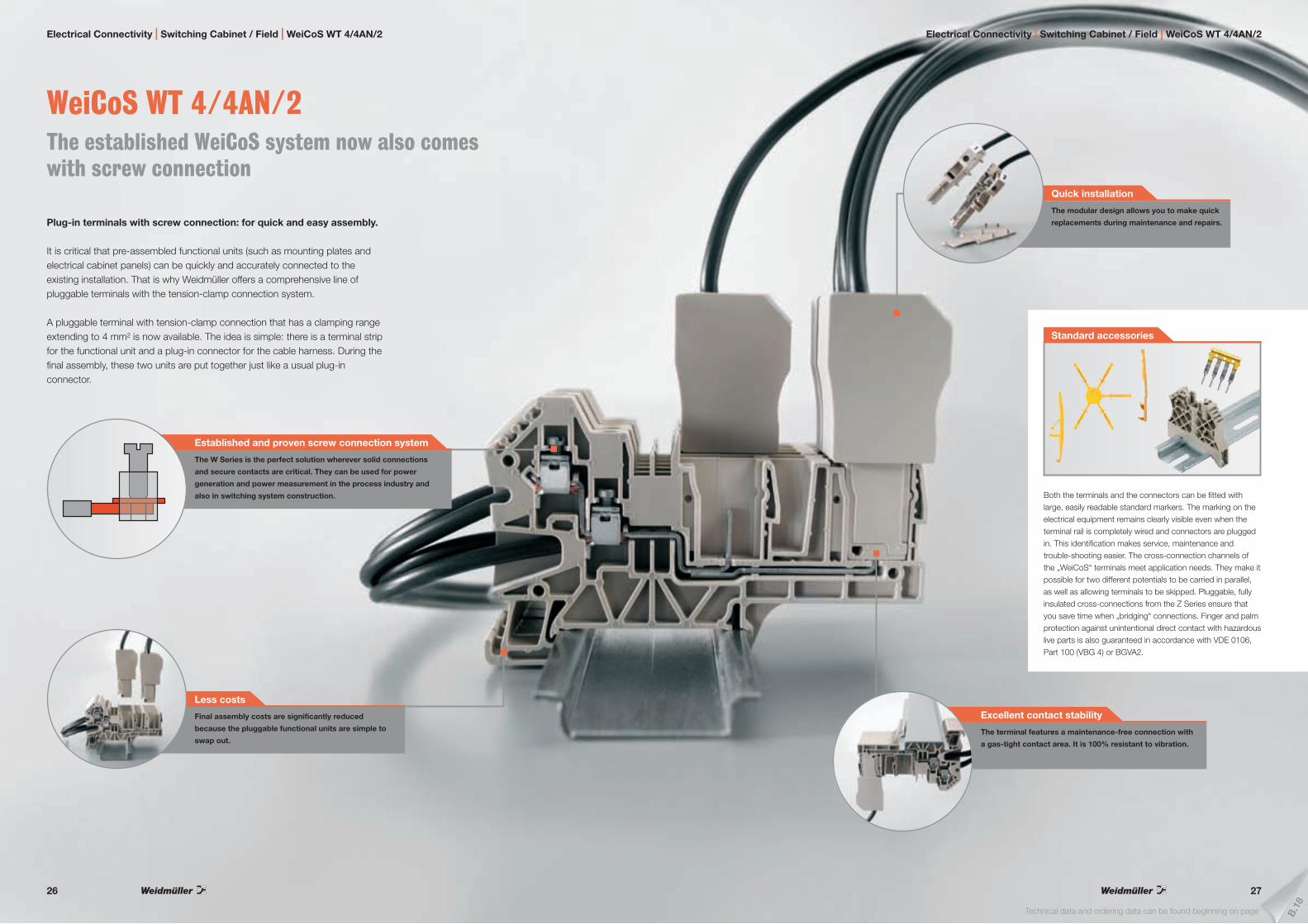
WeiCoS WT 4/4AN/2 The established WeiCoS system now also comes with screw connection
Plug-in terminals with screw connection: for quick and easy assembly.
It is critical that pre-assembled functional units (such as mounting plates and electrical cabinet panels) can be quickly and accurately connected to the existing installation. That is why Weidmüller offers a comprehensive line of pluggable terminals with the tension-clamp connection system.
A pluggable terminal with tension-clamp connection that has a clamping range extending to 4 mm² is now available. The idea is simple: there is a terminal strip for the functional unit and a plug-in connector for the cable harness. During the final assembly, these two units are put together just like a usual plug-in connector.
B.1
8
Technical data and ordering data can be found beginning on page
Electrical Connectivity | Switching Cabinet / Field | WeiCoS WT 4/4AN/2 Electrical Connectivity | Switching Cabinet / Field | WeiCoS WT 4/4AN/2
The terminal features a maintenance-free connection with
a gas-tight contact area. It is 100% resistant to vibration.
Excellent contact stability
The modular design allows you to make quick
replacements during maintenance and repairs.
Quick installation
Final assembly costs are significantly reduced
because the pluggable functional units are simple to
swap out.
Less costs
Standard accessories
Both the terminals and the connectors can be fitted with large, easily readable standard markers. The marking on the electrical equipment remains clearly visible even when the terminal rail is completely wired and connectors are plugged in. This identification makes service, maintenance and trouble-shooting easier. The cross-connection channels of the „WeiCoS“ terminals meet application needs. They make it possible for two different potentials to be carried in parallel, as well as allowing terminals to be skipped. Pluggable, fully insulated cross-connections from the Z Series ensure that you save time when „bridging“ connections. Finger and palm protection against unintentional direct contact with hazardous live parts is also guaranteed in accordance with VDE 0106, Part 100 (VBG 4) or BGVA2.
The W Series is the perfect solution wherever solid connections
and secure contacts are critical. They can be used for power
generation and power measurement in the process industry and
also in switching system construction.
Established and proven screw connection system
26 27

Fuse-distribution terminal ZSI 2x6/4x2.5 Just one terminal for fusing and distributing power
The new ZSI fuse-distribution terminal integrates fusing and distribution functionality into a single product.
This power distributor helps save space with its two power-in terminals and four outgoing feeders. The standardized ETA-fuse mating profile allows this product to be used in a wide variety of facility fuse protection applications. This standard profile makes it easy to use many accessories such as test adapters, fuses or labels.
Electrical Connectivity | Switching Cabinet / Field | Fuse-distribution terminal ZSI 2x6/4x2.5 Electrical Connectivity | Switching Cabinet / Field | Fuse-distribution terminal ZSI 2x6/4x2.5
The terminal is resistant to vibrations up to 5 g.
It is ideal for use in compact industrial machines
and vehicles (such as broaching machines or
construction machinery).
Resistant to vibration
This terminal is used for both power distribution
and facility fuse protection. Because of its
typical automotive fuse mating profile, this
product can be used in many applications.
Increased versatility
This functional integration means less space is required
for the wiring. The terminal with its six connection
options takes up less space.
Input: two plug-in contacts (6 mm²)
Output: four plug-in contacts (2.5 mm²)
Space and cost savings
B.1
9
Technical data and ordering data can be found beginning on page
The two labelling channels (one on each side)
provide for clarity in the electrical cabinet and
make it easy to prioritize and assign circuits.
Simple options for labelling
28 29

PS ZQV test probe Hand-free testing with a self-attaching test probe
The PS ZQV test probe allows you to commission and service a facility with hands-free convenience.
You can make adjustments while the test probe is snugly inserted into the cross-connection channel. The probe always penetrates deeply enough into the terminal to ensure no risk for your fingers.
The test probe can be connected via standard measurement cables and a 4 mm plug to most typical measuring instruments.
The test probe allows you to carry out safe, hands-free testing of
the wiring. It is inserted directly into the cross-connection channel
on the busbar and needs no additional support.
Test probes are self-securing
B.2
0
Technical data and ordering data can be found beginning on page
Electrical Connectivity | Switching Cabinet / Field | PS ZQV test probe Electrical Connectivity | Switching Cabinet / Field | PS ZQV test probe
The test sets are touch-safe and comply with the
requirements of IEC 1010.
Touch-safe
The new ZTA ZDK 2.5 test adapter
The new version of the ZTA ZDK 2.5 test adapter can be used for both double-tier and triple-tier terminals.
Digital multimeter
Multimeters are capable of measuring a number of variables. Each multimeter can measure voltage and resistance, as well as performing continuity and diode testing. The Weidmüller portfolio of tool products includes a wide variety of measurement and testing instruments for many different applications.
IEC 60529
A
L1
Z
T
The test probe fits into all cross-connection channels on
Weidmüller terminals (including the W, Z, I and P series).
It can also be used with the Plug, Wave and Micro series
from the Electronics portfolio.
Many possible usage methods
30 31

OMNIMATE POWER on BOARD Integrative connection systems for innovative drive applications
The OMNIMATE POWER system excels in power electronics and drive application due to the consistent implementation of customer and market requirements.
Custom-fit connection solutions for power electronics – resulting from the synergy between application-oriented components, individual services and competent design-in support.
The following pages show why OMNIMATE POWER is the ideal system for power electronics and drive applications. This system has benefited from our broader perspective due to the consideration of end use standards, and our consistent implementation of market and customer requirements.
Electrical Connectivity | Device / PCB | Connection systems for drive applications
OMNIMATE POWER ranks safety – down to the smallest detail – as
a top priority: this includes enhanced finger safety, protection
against incorrect use, overload capability, compliance with
household appliance standards and much more.
Performance + Safety
Designed with future requirements in mind: hybrid design
concepts create an efficient solution from two distinct
elements, for instance like the power-signal-EMC-hybrid
connector.
Performance + Innovation
Electrical Connectivity | Device / PCB | Connection systems for drive applications
OMNIMATE POWER at a glance
The single-source solution that omits no necessary components – a result of Weidmüller‘s technology and application expertise – delivers the optimal designed-in results.
The following pages describe the individual product lines in detail.
Design-In-Services & Support
The path to top results starts before component selection and does not end with delivery. More information can be found in the “Services & Support” brochure (order number 1077680000) or at www.galaxy.weidmueller.com
Power – Signal – Data
Weidmüller‘s connection strategy for power electronics, automation and drive applications joins power and signals. It also takes advantage of innovative EMC protection for data transmissions between the communications modules.
Customized services supplement our
comprehensive standard portfolio. The
housing colour, printing, coding, contact
surfaces, packaging and much more can
be configured online with just a few
mouse clicks.
Performance + Services
Weidmüller delivers more than just
components: our design-in competence
– encompassing work from design and
implementation to the market release
phase – delivers the top results.
Performance + Support
32 33

OMNIMATE POWER for IT systems – Scalable up to 50 kVACustom-fit solutions for special requirements
Increased compliance with end- use standards at less compromises: OMNIMATE POWER for IT systems establishes a new level of excellence with its standard integrated details. These attributes streamline the design-in and approval processes and result in safer operations.
This approach delivers evident advantages for the application as well as user benefits, such as: unlimited use in 400 V IT systems and touch safety according to IEC 61800-5-1 (+ 5.5 mm). The self-locking one-handed safety flange enables intuitive and safe usage. Operational reliability is ensured by the automatic interlock feature during the plug-in process. In conclusion: No additional device covering required. The application-oriented design means that no compromises are necessary during the approval process.
Electrical Connectivity | Device / PCB | BLZ 7.62 IT MF / BVZ 7.62 IT MF / BUZ 10.16 IT MF
C.2Technical data and ordering data can be found beginning on page
Electrical Connectivity | Device / PCB | BLZ 7.62 IT MF / BVZ 7.62 IT MF / BUZ 10.16 IT MF
IEC 61800-5-1:2007
A
L1
Z
T
Finger safety, acc. to DIN EN 61800-5-1
Since the end of 2007, device approval according to IEC Directive „Adjustable speed electrical power drive systems – Part 5-1: Safety requirements“ requires additional distances between test finger and life parts according to the line-to-earth voltage – in order to achieve additional finger safety (for example, + 3 mm for 400 V-TN systems (line-to-earth voltage = 230 V), or + 5 mm for 400 V-IT systems (line-to-earth voltage up to 400 V in case of error)). An additional cover is required for the wiring section of a device if the connection system does not fulfil these requirements. The OMNIMATE POWER HP product line already complies with the stricter IEC requirements for additional finger safety.
Clearance and creepage distances, acc. to UL
It goes without saying that plug-in connectors rated for 600 V must be approved according the UL 1059 component standard, if determined for the us market. But, beyond the component directives, it is about to still meet the requirements of the end use standard (e.g. UL 508C), when the component is an integrated part of the device, if one wants to avoid comprimises that lead to restrictions like just being „recognized“ but not „listed“, or redesigns and additional measures such as coatings and covers. That is why the OMNIMATE POWER series provides sufficient creepages and clearances related to the surrounding device. The OMNIMATE POWER HP product line already complies with the UL requirements for 600 V creepage and clearance distances.
Uncompromised means high power reserves for superior overload
capacity even at the high ambient temperatures of real-life
applications.
Uncompromised power capabilities
As much power as required, as little cost as possible: a
connector series that perfectly suits every performance
level and drive type: scalable from 25 A/2.5 mm² to
41 A/6 mm² to 76 A/16 mm².
Uncompromised scalability
LISTED instead of Recognized! No limitation for
UL approval with 600 V applications: with
optimized creepage and clearance distances
even under difficult installation situations.
Uncompromised UL approval
No extra measures or compromise needed for approval due to
application-oriented finger safety according to IEC 61800-5-1:
+ 3.0 mm for 400 V-TN systems
+ 5.5 mm for 400 V-IT systems
Uncompromised IEC approval
With details such as: insulated contact tips which ensure
that the pin header is touch-safe, or automatic snap-in for
a secure interlocking connection.
Uncompromised safety
600 V{
34 35

OMNIMATE POWER SL / BL 7.62HP – The 12 kVA power classCustom-fit solutions for compact devices
Compact power for more safety and efficiency: The compact model of the OMNIMATE POWER SL / BL 7.62HP connector series integrates previously-conflicting market requirements to provide a custom-fit solution for drive applications.
This closes the gap between increasing miniaturisation and unlimited 600 V UL approval. The system extension to the 12 kVA power class enables a finger-safe, inverted motor connection that is secured by the unique one-handed safety interlock. The PUSH IN connection technology also provides a quick and reliable wire connection. Double-sided finger safety ensures full protection even with reverse voltages. Thus even OMNIMATE POWER‘s compact class is qualified for use with the DC link bus.
No additional measures required for DC links or reverse
voltage: the inverted versions have finger-safe pin headers
and socket blocks – even when not plugged in.
Compact safety
Utilise maintenance-free and vibration-proof connections,
through quick and simple PUSH IN connections, or the
self-tightening Weidmüller steel clamping yoke with
plus/minus screw and WIRE GUARD feature.
Compact reliability
Electrical Connectivity | Device / PCB | BLL / SLF / SLZ / BLF 7.62HP
C.1
8
Technical data and ordering data can be found beginning on page
Tool-free simplicity: intuitive interlocking with the unique lock-
and release lever for easy and component-friendly latch and
release, or automatic and convenient attachment with one-
handed safety interlock.
Compact efficiency
Compact system power
The OMNIMATE POWER 12 kVA class at a glance:The compact system features a standard or inverted mating profile, screw or PUSH IN wire connection, and is optionally available with lock-n-release-lever, screw flange or one-handed safety interlock.
Individualised configuration
Standard + Services = individualised design – fast and easy through simple configuration from a wide range of services:Features include colour coding, application-oriented labelling and custom modifications or design. More information can be found in the „“Services & Support““ brochure (order number 1077680000) or at www.galaxy.weidmueller.com
No compromises during design and approval:
compact but even compliant to end-use
standards due to additional + 3.0 mm finger
safety, according to IEC 61800-5-1, and
increased creepage and clearance distances
according to UL.
Compact integration
Electrical Connectivity | Device / PCB | BLL / SLF / SLZ / BLF 7.62HP
Unrivalled current-carrying capacity
The highest load capacity in the 12 kVA compact class: with up to 29 A current-carrying capacity at 1000 V (IEC) with a 4 mm² wire cross-section, or 18.5 A at 600 V according to UL.
36 37

OMNIMATE POWER SV / BV 7.62HP – The 28 kVA power classCustom-fit high-powered solutions
More power reserves for more load capacity: The OMNIMATE POWER SV / BV 7.62HP with its large clamping range, increased overload capacity and widest selection of variants and accessories is the high performer of the HP product line.
HP means High Performance – this performance covers a full 41 A rated current, even up to an ambient operational temperature of 55 °C, unlimited 600 V approval according to UL, additional finger safety for 400 V-TN systems (+ 3.0 mm) in accordance with the application directive IEC 61800-5-1, and also in compliance with the domestic appliance directive DIN EN/IEC 60335-1.
Full current rating up to 40 °C ambient temperature is a
mandatory requirement in drive applications. What really
makes the difference here is real-life, application-based
overload and peak temperature capacities.
Maximum performance
Weidmüller‘s WEMID insulating material – featuring a GWIT
(glow wire ignitability test) of > 775 °C – also complies with the
domestic appliance directive DIN EN/IEC 60335-1.
Maximum conformity
Safe for both man and machine with
bi-directional finger safety: also when
not plugged in and covering reverse
voltages from power electronics.
Maximum safety
Electrical Connectivity | Device / PCB | BVF / SVF 7.62HP
C.2
8
Technical data and ordering data can be found beginning on page
High system performance
The OMNIMATE POWER 28 kVA class at a glance: The HP system has been leading the way with its tool-free rapid interlock, installation-safe creepage and clearance distances, and application-oriented range of variants. Introducing the unique one-handed safety flange and a wide range of innovative features, the system expansion again provides advanced technology for innovative applications.
Individualised configuration
Standard + Services = individualised design with simple configuration from a wide range of services:Features include colour coding, application-oriented labelling and custom modifications or design. More information can be found in the “Services & Support” brochure (order number 1077680000) or at www.galaxy.weidmueller.com
Electrical Connectivity | Device / PCB | BVF / SVF 7.62HP
Quick, simple and intuitive plug and release: with
the one-handed safety flange – convenient for the
user and safe for the application.
Maximum usability
Tool-free simplicity: intuitive, quick PUSH IN connection
technology and automatic, convenient attachment with
one-handed safety interlock.
www.push-in.com
Maximum efficiency
ä
ä
38 39

OMNIMATE POWER SV / BV 7.62HP Hybrid –for power, signals and EMCThree functions in one!
The OMNIMATE POWER Hybrid connector provides developers and users with the perfect three-in-one solution.
This hybrid motor connector simultaneously mates power, signals and pluggable EMC screen connection. Thus you save space on the PCB, at the device housing, and in the electrical cabinet. Including the engagement of the automaticly self-securing one-handed interlock mechanism, the connector requires only one plugging step instead of 3 and thus speeds up installation and maintenance procedures. It is easy to handle and interlocks automatically – even in difficult installation positions. The unique shielding shape with a slender 30° wire entry enable space savings of up to 10 cm between the device rows within a cabinet.
Plug & Go: intuitive handling: through tool-free one-handed
operation with automatic interlocking and also „blind“ plugging of
power, signals and EMC-shielding simultaneously.
Unique interaction
Electrical Connectivity | Device / PCB | SV / BVF 7.62HP Hybrid
More space available on the PCB providing for denser component
assemblies, and more space available on the housing wall because
of true-to-pitch integration of the signal contacts – while
maintaining the same width!
Unique density
C.4
2
Technical data and ordering data can be found beginning on page
This three-in-one solution – with its pluggable EMC
screen connection, integrated signal contacts and
one-handed security flange – can replace 3 distinct
components and 3 steps in the workflow.
Unique integration
EMC in drive applications
The motor feedback (temperature/encoder signals) in hybrid, shield-within-shield motor cables is usually connected through over-sized power contacts or with seperate I/O connectors. It also normally requires two additional shield fasteners. During installation and maintenance (replacement), it is a risk that the shield clamp is incorrectly connected, even disconnected or lost. With conventional shielding, it can be quite difficult to tighten the flange screws when the connection is located under the device or any position hardly. So this step is often neglected, which regularly leads to faults as described below.
Reliably avoid EMC-issues
As a result, malfunctions due to interferrences can then be caused by the coupling of electromagnetic fields to the sensitive electronics. The pluggable, hybrid shield support features a special EMC spring-contact strip which ensures that the shield connection to the housing is permanent, vibration-proof and covers a large surface area. It allows the shielding braid from the power and signal wires to be connected separately – and enables this to be done automatically in one step so that it is not dependent on the user s accuracy.
Electrical Connectivity | Device / PCB | SV / BVF 7.62HP Hybrid
Integrating functions, optimizing processes,
and reducing complexity: The conventional
2 outer flanges have simply been replaced by
1 middle flange, 4 signal contacts and 1
pluggable EMC screen connection.
Unique innovation
Safe, EMC-compliant screen connection for any
application situation and with no risk of insufficient
shielding.
Unique safety
Topology of parasitic currents
low parasitic currents high parasitic currents
Source: Frauenhofer IZM
40 41

Electrical Connectivity | Device / PCB | OMNIMATE HOUSINGS CH20M
Functional Design
Our comprehensive, standardized configuration set can be further supplemented with modification and design customer-specific devellopment to exactly meet your individual requirements.
Visual Design
The synergy of modularity and variety enables you to customize a wide range of designs to fit your application, even with the available standard modules.
Detailed symbols, data, graphics or text can be plainly
printed (with either laser or Tampo-pad printing) on each
surface of the housing elements.
Design-option: marking
Modification options complement the configuration set: for example by
integrating the pluggable 30-pole digital I/O connection device BL-I/O
LED into the FRONT-module or a RJ45 socket into the SIDE-module.
Design-option: modification
OMNIMATE HOUSINGS CH20M Individual design by combining options of more form, function and appearance
CH20M (Component Housing IP20 Modular) – Weidmüller‘s new housing standard – represents the ideal platform for individually customized electronic applications.
Like a “tailor-made suit straight off the rack”, the groundbreaking module concept combines freedom in design with the low cost and planning security of a standard system.
In addition to scalability, a high level of safety and innovative functionality in the application, the system also excels with a comprehensive range of design options.
The results are quicker installation, user-friendly operation, high operational reliability and resistance to interference. From development to production, the CH20M represents efficiency. It covers all of the requirements for a modern electronics platform built with the future in mind.
More operational confidence with functionally
appropriate colour coding: three functional colours
(red, yellow and blue coding) can be assigned to key
industrial applications.
Design-option: functional colours
Electrical Connectivity | Device / PCB | OMNIMATE HOUSINGS CH20M
With a focus on the important elements: the unobtrusive housing
colours (black graphite, grey graphite and light grey) provide
professional appearance without distracting from the key
operational and display elements.
Design-option: basic colours
As many connections as required and as affordable as
possible: scalable connection levels, custom-configurable
for each side and available with four different housing
widths with up to 72 single wire connections.
Design-option: configuration
42 43

Ele
ctro
nics
A
Electronics | Contents
Electronics
PRO-M
Power supplies for space-savinguse in automation technology
A.2
ACT20X
Universal, intrinsically safe signal conditioners for hazardous area applications
A.8
WAVE TTA
Universal signal converters and trip amplifers
A.13
ACT20P Bridge
Strain gauge transmitter for reading load cells
A.14
VARITECTOR SPC
Pluggable surge protection for C&I circuits
A.16
VARITECTOR SSC 4AN
Surge protection fit into a 6-mm width for measurement and control circuits
A.44
PLC Front Adaptor (FAD)
New Front Adaptors for different PLC Cards
A.54
RSF PLC
Direct inputs/outputs for digital cards
A.62
RSM
Isolated inputs/outputs for digital cards
A.65
RS ELCO
Interface units and pre-assembled cables with ELCO connectors
A.70
RS VERT
Passive interface components for distibuting AC and DC supply voltages
A.74
Photovoltaic junction box
Innovative junction box for photovoltaic modules with a rated current of max. 8.5 A
A.76
Stringbox (PV-BOX)
The custom solution for safety in photovoltaic systems
A.78
44 A.1
A.2
Ele
ctro
nics
A
A.3
Ele
ctro
nics
A
Electronics | PRO-M
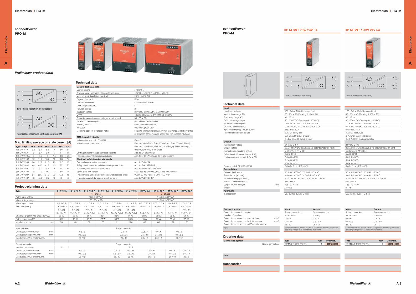
connectPowerPRO-M
Preliminary product data!
Two-Phase operation also possible
Permissible maximum continuous current [A]
Max. limiting average on state current [A]Type\Temp. 45°C 50°C 55°C 60°C 65°C 70°C1ph 24V / 3A 3.6 3.4 3.2 3 2.6 2.3
1ph 24V / 5A 6 5.7 5.3 5 4.4 3.8
1ph 24V / 7.5A 9 8.5 8 7.5 6.6 5.6
1ph 24V / 10A 12 11.3 10.7 10 8.8 7.5
1ph 24V / 20A 24 22.7 21.3 20 17.5 15
1ph 24V / 40A 48 45.3 42.7 40 35 30
3ph 24V / 5A 6 5.7 5.3 5 4.4 3.8
3ph 24V / 10A 12 11.3 10.7 10 8.8 7.5
3ph 24V / 20A 24 22.7 21.3 20 17.5 15
3ph 24V / 40A 48 45.3 42.7 40 35 30
Technical dataGeneral technical dataCurrent limiting > 120 % INAmbient temp. operating / storage temperature –25 °C … +70 °C / –40 °C … +85 °C
Max. perm. air humidity (operation) 20 %…95 % RH
Degree of protection IP20
Class of protection I, with PE connection
Overvoltage category II
Pollution degree 2
Insulation voltage 3 kV I/O / 2 kV I/earth / 0.5 kV O/earth
MTBF > 500,000 h acc. to IEC 1709 (SN29500)
Protection against reverse voltages from the load 30…35 V DC
Parallel connection option yes, without diode module
Housing version metal, corrosion resistant
Indication operation, green LED
Mounting position, installation notice horizontal on mounting rail TS35, 80 mm spacing top and bottom for free
air circulation, can be mounted side by side with no space in between
EMC / shock / vibrationNoise emission acc. to EN55022 Class B
Noise immunity tests acc. to EN61000-4-2 (ESD), EN61000-4-3 und EN61000-4-8 (Fields),
EN61000-4-4 (Burst), EN61000-4-5 (Surge), EN610004-6 (con-
ducted), EN61000-4-11 (Dips)
Limiting of mains voltage harmonic currents Acc. to EN 61000-3-2
Resistance against vibration and shock Acc. to EN50178, shock: 5g in all directions
Electrical safety (applied standards)Electrical equipment of machines Acc. to EN60204
Safety transformers for switched-mode power units Acc. to EN61558-2-17
Machinery with electronic equipment Acc. to EN50178 / VDE0160
Safety extra-low voltage SELV acc. to EN60950, PELV acc. to EN60204
Protective separation / protection against electrical shock VDE0100-410 / acc. to DIN57100-410
Protection against dangerous shock currents Acc. to VDE0106-101
Project-planning dataType 24 V / 3 A 24 V / 5 A 24 V / 7.5 A 24 V / 10 A 24 V / 20 A 24 V / 40 A 24 V / 5 A 24 V / 10 A 24 V / 20 A 24 V / 40 A
1 - phase 3 - phase
Rated input voltage 100...240 V AC 3 x 400...500 V AC
Mains voltage range 85...264 V AC 3 x 320...575 V AC
Mains input current 1.3...0.6 A 2.1...0.9 A 2.1...0.9 A 2.8...1.2 A 5.6...2.4 A 11.1...4.7 A 0.3...0.28 A 0.55...0.5 A 1.0...0.9 A 2.5...2.0 A
Rec. fuse [char..] 2 A / D I / II 4 A / D I / II 6 A / D I / II 6 A / D I / II 10 A / D I / II 16 A / D I / II 2 A / D I / II 2 A / D I / II 2 A / D I / II 4 A / D I / II
6 A, [B] 6 A, [B] 16 A, [B] 16 A, [B] 20 A, [B] 25 A, [B] - - - 10 A, [B]
2...4 A, [C] 3...5 A, [C] 5...10 A, [C] 5...10 A, [C] 10...12 A, [C] 14...16 A, [C] 1...2 A, [C] 2...3 A, [C] 3...5 A, [C] 6...8 A, [C]
Efficiency @ 230 V AC, @ 3x400 V AC 90 % 90 % 91 % 90 % 90 % 91 % 90 % 90 % 90 % 91 %
Rated power loss [W] 8 W 13 W 18 W 27 W 53 W 95 W 13 W 27 W 53 W 95 W
Installation width mm 33 40 50 60 121 180 40 60 121 180
Input terminals Screw connection
Conductor, solid min/max mm2 0.5...6 0.5...6 0.08...4 0.5...6 0.5...6
Conductor, flexible min/max mm2 0.5...2.5 0.5...2.5 0.5...2.5 0.5...2.5 0.5...2.5
Conductor, AWG/kcmil min/max 26 / 12 26 / 10 28 / 12 26 / 12 26 / 12
Output terminals Screw connection
Number plus/minus 2 / 2 2 / 3
Conductor, solid min/max mm2 0.5...6 0.5...6 0.5...16 0.5...6 0.5...6 0.5...16
Conductor, flexible min/max mm2 0.5...2.5 0.5...2.5 2.5...10 0.5...2.5 0.5...2.5 2.5...10
Conductor, AWG/kcmil min/max 26 / 12 26 / 10 22 / 6 26 / 12 26 / 10 22 / 6
+
–
L (+)
N (–)
PE DCAC
+
–
L1 (+)
L2 (–)
L3
PE DCAC
connectPower PRO-M
H
L
W
Technical dataInputrated input voltageInput voltage range ACFrequency range ACDC input voltage rangeAC current consumptionDC current consumptionInput fuse (internal) / inrush currentRecommended back-up fuse
Outputrated output voltageOutput voltageresidual ripple, breaking spikesRated (nominal) output current @ UN
continous output current @ 24 V DC
Powerboost @ 24 V DC, 60 °CGeneral dataDegree of efficiencyPower factor (approx.)AC failure bridging time @ INParallel connection optionLength x width x height mmWeightApprovalsin preparation
Connection dataConductor connection systemNumber of terminalsConductor cross-section, rigid min/max mm² Conductor cross-section, flexible min/max mm² Conductor cross-section, AWG/kcmil min/max
Note
Ordering dataConnection system
Screw connection
Note
Accessories
CP M SNT 70W 24V 3A
+
–
L (+)
N (–)
PE DCAC
With DC connection, note polarity
100...240 V AC (wide-range input) 85...264 V AC (Derating @ 100 V AC)47...63 Hz 80…370 V DC (Derating @ 120 V DC) 0.6 A @ 230 V AC / 1.1 A @ 115 V AC 0.25 A @ 370 V DC / 0.7 A @ 120 V DCyes / max. 40 A2 A / DI, safety fuse
6 A, Char. B, circuit breaker
2...4 A, Char. C, circuit breaker
24 V DC ± 1 % 22.5...24.5 V DC (adjustable via potentiometer on front) < 50 mVSS @ 24 V DC, IN3 A @ 60 °C 3.6 A @ 45 °C
3.2 A @ 55 °C
2.3 A @ 70 °C 3.6 A for 1 min, ED = 5 %
90 % @ 230 V AC / 88 % @ 115 V AC > 0.6 @ 230 V AC / > 0,65 @ 115 V AC > 100 ms @ 230 V AC / > 20 ms @ 115 V ACyes, max. 5125 / 33 / 1300.57 kg
CE, cURus, cULus, C-Tick
Input OutputScrew connection Screw connection3 for L/N/PE 4 (++--)0.5 / 6 0.5 / 60.5 / 2.5 0.5 / 2.526 / 12 26 / 12*) Recommendation applies only for AC operation; the max. permissible operating voltage must be observed in all cases!
Type Qty. Order No.
CP M SNT 70W 24V 3A 1 8951330000
CP M SNT 120W 24V 5A
100...240 V AC (wide-range input) 85...264 V AC (Derating @ 100 V AC)47...63 Hz 80…370 V DC (Derating @ 120 V DC) 1.1 A @ 230 V AC / 2.0 A @ 115 V AC 0.4 A @ 370 V DC / 1.2 A @ 120 V DCyes / max. 40 A4 A / DI, safety fuse
6 A, Char. B, circuit breaker
3...5 A, Char. C, circuit breaker
24 V DC ± 1 % 22.5...24.5 V DC (adjustable via potentiometer on front) < 50 mVSS @ 24 V DC, IN5 A @ 60 °C 6.0 A @ 45 °C
5.3 A @ 55 °C
3.8 A @ 70 °C 6 A for 1 min, ED = 5 %
90 % @ 230 V AC / 88 % @ 115 V AC > 0.5 @ 230 V AC / > 0.6 @ 115 V AC > 100 ms @ 230 V AC / > 20 ms @ 115 V ACyes, max. 5125 / 40 / 1300.7 kg
CE, cURus, cULus, C-Tick
+
–
L (+)
N (–)
PE DCAC
With DC connection, note polarity
Input OutputScrew connection Screw connection3 for L/N/PE 5 (++---)0.5 / 6 0.5 / 60.5 / 2.5 0.5 / 2.526 / 12 26 / 12*) Recommendation applies only for AC operation; the max. permissible operating voltage must be observed in all cases!
Type Qty. Order No.
CP M SNT 120W 24V 5A 1 8951340000
Electronics | PRO-M

A.4
Ele
ctro
nics
A
A.5
Ele
ctro
nics
A
connectPower PRO-M
H
L
W
Technical dataInputrated input voltageInput voltage range ACFrequency range ACDC input voltage rangeAC current consumptionDC current consumptionInput fuse (internal) / inrush currentRecommended back-up fuse
Outputrated output voltageOutput voltageresidual ripple, breaking spikesRated (nominal) output current @ UN
continous output current @ 24 V DC
Powerboost @ 24 V DC, 60 °CGeneral dataDegree of efficiencyPower factor (approx.)AC failure bridging time @ INParallel connection optionLength x width x height mmWeightApprovalsin preparation
Connection dataConductor connection systemNumber of terminalsConductor cross-section, rigid min/max mm²Conductor cross-section, flexible min/max mm²Conductor cross-section, AWG/kcmil min/max
Note
Ordering dataConnection system
Screw connection
Note
Accessories
CP M SNT 500W 24V 20A
+
–
L (+)
N (–)
PE DCAC
With DC connection, note polarity
100...240 V AC (wide-range input) 85...264 V AC (Derating @ 100 V AC)47...63 Hz 80…370 V DC (Derating @ 120 V DC) 2.4 A @ 230 V AC / 4.8 A @ 115 V AC 1.5 A @ 370 V DC / 4.6 A @ 120 V DCyes / max. 5 A6 A / DI, safety fuse
16 A, Char. B, circuit breaker
6…8 A, Char. C, circuit breaker
24 V DC ± 1 %22.5...29.5 V DC (adjustable via potentiometer on front) < 50 mVSS @ 24 V DC, IN20 A @ 60 °C 24 A @ 45 °C
22.7 A @ 55 °C
15 A @ 70 °C 24 A for 1 min, ED = 5 %
90 % at 230 V AC / > 85 % at 115 V AC > 0.98 @ 230 V AC / > 0.99 @ 115 V AC > 20 ms @ 230 V AC / > 20 ms @ 115 V ACyes, max. 3150 / 121 / 1302.2 kg
CE, cURus, cULus, C-Tick
Input OutputScrew connection Screw connection3 for L/N/PE 5 (++---)0.5 / 6 0.5 / 60.5 / 2.5 0.5 / 2.526 / 10 26 / 10*) Recommendation applies only for AC operation; the max. permissible operating voltage must be observed in all cases!
Type Qty. Order No.
CP M SNT 500W 24V 20A 1 8951370000
CP M SNT 1000W 24V 40A
100...240 V AC (wide-range input) 85...264 V AC (Derating @ 100 V AC)47...63 Hz 80…370 V DC (Derating @ 120 V DC) 4.7 A @ 230 V AC / 9.6 A @ 115 V AC 2.9 A @ 370 V DC / 9.1 A @ 120 V DCyes / max. 5 A16 A / DI, safety fuse
20 A, Char. B, circuit breaker
16 A, Char. C, circuit breaker
24 V DC ± 1 %22.5...29.5 V DC (adjustable via potentiometer on front) < 50 mVSS @ 24 V DC, IN40 A @ 60 °C48 A @ 45 °C
42.7 A @ 55 °C
30 A @ 70 °C 48 A for 1 min, ED = 5 %
91 % @ 230 V AC / 88 % @ 115 V AC > 0.99 @ 230 V AC / > 0.99 @ 115 V AC > 20 ms @ 230 V AC / > 20 ms @ 115 V ACyes, max. 3150 / 180 / 1303.9 kg
CE, cURus, cULus, C-Tick
+
–
L (+)
N (–)
PE DCAC
With DC connection, note polarity
Input OutputScrew connection Screw connection3 for L/N/PE 5 (++---)0.5 / 6 0.5 / 160.5 / 2.5 2.5 / 1026 / 10 22 / 6*) Recommendation applies only for AC operation; the max. permissible operating voltage must be observed in all cases!
Type Qty. Order No.
CP M SNT 1000W 24V 40A 1 8951380000
Electronics | PRO-M
connectPower PRO-M
H
L
W
Technical dataInputrated input voltageInput voltage range ACFrequency range ACDC input voltage rangeAC current consumptionDC current consumptionInput fuse (internal) / inrush currentRecommended back-up fuse
Outputrated output voltageOutput voltageresidual ripple, breaking spikesRated (nominal) output current @ UN
continous output current @ 24 V DC
Powerboost @ 24 V DC, 60 °CGeneral dataDegree of efficiencyPower factor (approx.)AC failure bridging time @ INParallel connection optionLength x width x height mmWeightApprovalsin preparation
Connection dataConductor connection systemNumber of terminalsConductor cross-section, rigid min/max mm²Conductor cross-section, flexible min/max mm²Conductor cross-section, AWG/kcmil min/max
Note
Ordering dataConnection system
Screw connection
Note
Accessories
CP M SNT 180W 24V 7.5A
+
–
L (+)
N (–)
PE DCAC
With DC connection, note polarity
100...240 V AC (wide-range input) 85...264 V AC (Derating @ 100 V AC)47...63 Hz 80…370 V DC (Derating @ 120 V DC) 0.9 A @ 230 V AC / 1.8 A @ 115 V AC 0.6 A @ 370 V DC / 1.7 A @ 120 V DCyes / max. 40 A6 A / DI, safety fuse,
10 A, Char. B, circuit breaker,
6 A, Char. C, circuit breaker
24 V DC ± 1 %22.5...29.5 V DC (adjustable via potentiometer on front) < 50 mVSS @ 24 V DC, IN7.5 A @ 60 °C 9.0 A @ 45 °C
8.0 A @ 55 °C
5.6 A @ 70 °C 9 A for 1 min, ED = 5 %
91 % @ 230 V AC / 88 % @ 115 V AC > 0.94 @ 230 V AC / > 0.99 @ 115 V AC > 20 ms @ 230 V AC / > 20 ms @ 115 V ACyes, max. 5125 / 50 / 1301.05 kg
CE, cURus, cULus, C-Tick
Input OutputScrew connection Screw connection3 for L/N/PE 5 (++---)0.5 / 6 0.5 / 60.5 / 2.5 0.5 / 2.526 / 12 26 / 12*) Recommendation applies only for AC operation; the max. permissible operating voltage must be observed in all cases!
Type Qty. Order No.
CP M SNT 180W 24V 7,5A 1 8951350000
CP M SNT 250W 24V 10A
100...240 V AC (wide-range input) 85...264 V AC (Derating @ 100 V AC)47...63 Hz 80…370 V DC (Derating @ 120 V DC) 1.2 A @ 230 V AC / 2.4 A @ 115 V AC 0.8 A @ 370 V DC / 2.3 A @ 120 V DCyes / max. 12 A4 A / DI, safety fuse
10 A, Char. B, circuit breaker
3...4 A, Char. C, circuit breaker
24 V DC ± 1 %22.5...29.5 V DC (adjustable via potentiometer on front) < 50 mVSS @ 24 V DC, IN10 A @ 60 °C 12 A @ 45 °C
10.7 A @ 55 °C
7.5 A @ 70 °C 12 A for 1 min, ED = 5 %
90 % @ 230 V AC / 87 % @ 115 V AC > 0.99 @ 230 V AC / > 0.97 @ 115 V AC > 20 ms @ 230 V AC / > 20 ms @ 115 V ACyes, max. 5150 / 60 / 1301.2 kg
CE, cURus, cULus, C-Tick
+
–
L (+)
N (–)
PE DCAC
With DC connection, note polarity
Input OutputScrew connection Screw connection3 for L/N/PE 5 (++---)0.5 / 6 0.5 / 65 / 2.5 0.5 / 2.526 / 12 26 / 12*) Recommendation applies only for AC operation; the max. permissible operating voltage must be observed in all cases!
Type Qty. Order No.
CP M SNT 250W 24V 10A 1 8951360000
Electronics | PRO-M
A.6
Ele
ctro
nics
A
A.7
Ele
ctro
nics
A
connectPower PRO-M
H
L
W
Technical dataInputrated input voltageInput voltage range ACFrequency range ACDC input voltage rangeAC current consumptionDC current consumptionInput fuse (internal) / inrush currentRecommended back-up fuse
Outputrated output voltageOutput voltageresidual ripple, breaking spikesRated (nominal) output current @ UN
continous output current @ 24 V DC
Powerboost @ 24 V DC, 60 °CGeneral dataDegree of efficiencyPower factor (approx.)AC failure bridging time @ INParallel connection optionLength x width x height mmWeightApprovalsin preparation
Connection dataConductor connection systemNumber of terminalsConductor cross-section, rigid min/max mm²Conductor cross-section, flexible min/max mm²Conductor cross-section, AWG/kcmil min/max
Note
Ordering dataConnection system
Screw connection
Note
Accessories
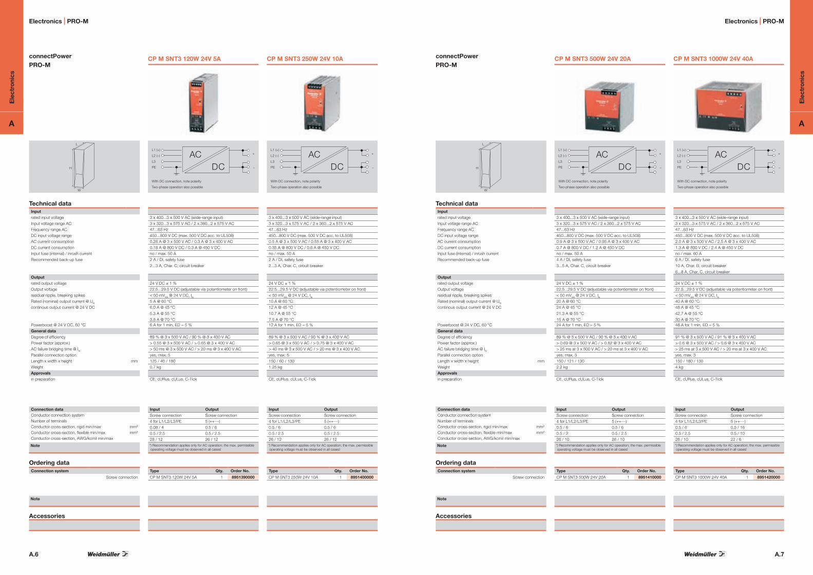
CP M SNT3 500W 24V 20A
+
–
L1 (+)
L2 (–)
L3
PE
With DC connection, note polarity
Two-phase operation also possible
DCAC
3 x 400...3 x 500 V AC (wide-range input) 3 x 320...3 x 575 V AC / 2 x 360...2 x 575 V AC 47...63 Hz 450...800 V DC (max. 500 V DC acc. to UL508) 0.9 A @ 3 x 500 V AC / 0.95 A @ 3 x 400 V AC 0.7 A @ 800 V DC / 1.2 A @ 450 V DCno / max. 50 A4 A / DI, safety fuse
3...5 A, Char. C, circuit breaker
24 V DC ± 1 %22.5...29.5 V DC (adjustable via potentiometer on front) < 50 mVSS @ 24 V DC, IN20 A @ 60 °C 24 A @ 45 °C
21.3 A @ 55 °C
15 A @ 70 °C 24 A for 1 min, ED = 5 %
89 % @ 3 x 500 V AC / 90 % @ 3 x 400 V AC > 0.69 @ 3 x 500 V AC / > 0.82 @ 3 x 400 V AC > 25 ms at 3 x 500 V AC / > 20 ms at 3 x 400 V ACyes, max. 3150 / 121 / 1302.2 kg
CE, cURus, cULus, C-Tick
Input OutputScrew connection Screw connection4 for L1/L2/L3/PE 5 (++---)0.5 / 6 0.5 / 60.5 / 2 0.5 / 2.526 / 10 26 / 10*) Recommendation applies only for AC operation; the max. permissible operating voltage must be observed in all cases!
Type Qty. Order No.
CP M SNT3 500W 24V 20A 1 8951410000
CP M SNT3 1000W 24V 40A
3 x 400...3 x 500 V AC (wide-range input) 3 x 320...3 x 575 V AC / 2 x 360...2 x 575 V AC 47...63 Hz 450...800 V DC (max. 500 V DC acc. to UL508) 2.0 A @ 3 x 500 V AC / 2.5 A @ 3 x 400 V AC 1.3 A @ 800 V DC / 2.4 A @ 450 V DCno / max. 60 A6 A / DI, safety fuse
10 A, Char. B, circuit breaker
6...8 A, Char, C, circuit breaker
24 V DC ± 1 % 22.5...29.5 V DC (adjustable via potentiometer on front) < 50 mVSS @ 24 V DC, IN40 A @ 60 °C48 A @ 45 °C
42.7 A @ 55 °C
30 A @ 70 °C 48 A for 1 min, ED = 5 %
91 % @ 3 x 500 V AC / 91 % @ 3 x 400 V AC > 0.6 @ 3 x 500 V AC / > 0.6 @ 3 x 400 V AC > 25 ms at 3 x 500 V AC / > 20 ms at 3 x 400 V ACyes, max. 3150 / 180 / 1304 kg
CE, cURus, cULus, C-Tick
+
–
L1 (+)
L2 (–)
L3
PE
With DC connection, note polarity
Two-phase operation also possible
DCAC
Input OutputScrew connection Screw connection4 for L1/L2/L3/PE 5 (++---)0.5 / 6 0.5 / 160.5 / 2.5 0.5 / 1026 / 10 22 / 6*) Recommendation applies only for AC operation; the max. permissible operating voltage must be observed in all cases!
Type Qty. Order No.
CP M SNT3 1000W 24V 40A 1 8951420000
Electronics | PRO-M
connectPower PRO-M
H
L
W
Technical dataInputrated input voltageInput voltage range ACFrequency range ACDC input voltage rangeAC current consumptionDC current consumptionInput fuse (internal) / inrush currentRecommended back-up fuse
Outputrated output voltageOutput voltageresidual ripple, breaking spikesRated (nominal) output current @ UN
continous output current @ 24 V DC
Powerboost @ 24 V DC, 60 °CGeneral dataDegree of efficiencyPower factor (approx.)AC failure bridging time @ INParallel connection optionLength x width x height mmWeightApprovalsin preparation
Connection dataConductor connection systemNumber of terminalsConductor cross-section, rigid min/max mm²Conductor cross-section, flexible min/max mm²Conductor cross-section, AWG/kcmil min/max
Note
Ordering dataConnection system
Screw connection
Note
Accessories
CP M SNT3 120W 24V 5A
+
–
L1 (+)
L2 (–)
L3
PE
With DC connection, note polarity
Two-phase operation also possible
DCAC
3 x 400...3 x 500 V AC (wide-range input) 3 x 320...3 x 575 V AC / 2 x 360...2 x 575 V AC 47...63 Hz 450...800 V DC (max. 500 V DC acc. to UL508) 0.28 A @ 3 x 500 V AC / 0.3 A @ 3 x 400 V AC 0.18 A @ 800 V DC / 0.3 A @ 450 V DCno / max. 50 A2 A / DI, safety fuse
2...3 A, Char. C, circuit breaker
24 V DC ± 1 %22.5...29.5 V DC (adjustable via potentiometer on front) < 50 mVSS @ 24 V DC, IN5 A @ 60 °C 6.0 A @ 45 °C
5.3 A @ 55 °C
3.8 A @ 70 °C 6 A for 1 min, ED = 5 %
89 % @ 3 x 500 V AC / 90 % @ 3 x 400 V AC > 0.55 @ 3 x 500 V AC / > 0.65 @ 3 x 400 V AC > 50 ms @ 3 x 500 V AC / > 20 ms @ 3 x 400 V ACyes, max. 5125 / 40 / 1800.7 kg
CE, cURus, cULus, C-Tick
Input OutputScrew connection Screw connection4 for L1/L2/L3/PE 5 (++---)0.08 / 4 0.5 / 60.5 / 2.5 0.5 / 2.528 / 12 26 / 12*) Recommendation applies only for AC operation; the max. permissible operating voltage must be observed in all cases!
Type Qty. Order No.
CP M SNT3 120W 24V 5A 1 8951390000
CP M SNT3 250W 24V 10A
3 x 400...3 x 500 V AC (wide-range input) 3 x 320...3 x 575 V AC / 2 x 360...2 x 575 V AC 47...63 Hz 450...800 V DC (max. 500 V DC acc. to UL508) 0.5 A @ 3 x 500 V AC / 0.55 A @ 3 x 400 V AC 0.35 A @ 800 V DC / 0.6 A @ 450 V DCno / max. 50 A2 A / DI, safety fuse
2...3 A, Char. C, circuit breaker
24 V DC ± 1 % 22.5...29.5 V DC (adjustable via potentiometer on front) < 50 mVSS @ 24 V DC, IN10 A @ 60 °C 12 A @ 45 °C
10.7 A @ 55 °C
7.5 A @ 70 °C 12 A for 1 min, ED = 5 %
89 % @ 3 x 500 V AC / 90 % @ 3 x 400 V AC > 0.65 @ 3 x 500 V AC / > 0.75 @ 3 x 400 V AC > 40 ms @ 3 x 500 V AC / > 20 ms @ 3 x 400 V ACyes, max. 5150 / 60 / 1301.25 kg
CE, cURus, cULus, C-Tick
+
–
L1 (+)
L2 (–)
L3
PE
With DC connection, note polarity
Two-phase operation also possible
DCAC
Input OutputScrew connection Screw connection4 for L1/L2/L3/PE 5 (++---)0.5 / 6 0.5 / 60.5 / 2.5 0.5 / 2.526 / 12 26 / 12*) Recommendation applies only for AC operation; the max. permissible operating voltage must be observed in all cases!
Type Qty. Order No.
CP M SNT3 250W 24V 10A 1 8951400000
Electronics | PRO-M

Ele
ctro
nics
A
A.8
Ele
ctro
nics
A
A.9
Electronics | ACT20X Electronics | ACT20X
Digital actuator driver
• Suitableforswitchingsolenoidvalves• Digitalinputsignalsfromsafearea• SuppliesdigitalactuatorsinExareaZone0• OptionalforgasgroupsIICandIIB• Erroroutput(alarm)• PCconfigurablewithFDT/DTMsoftware• six-wayisolation(2-channelversion)
PS PS
Technical dataInput (digital)Type
Lowtriggervoltage(NPN)
Hightriggervoltage(NPN)
Switchingcurrent(NPN)
Lowtriggervoltage(PNP)
Hightriggervoltage(PNP)
Switchingcurrent(PNP)
Output (digital)
Type
max.continuouscurrent
Alarm
Type
max.switchingvoltage/max.switchingvoltageExZone2
max.switchingpower/max.switchingpowerEXZone2
General data
Supplyvoltage
Powerconsumption
Stepresponsetime
Ambienttemperature(operational)
Storagetemperature
Approvals
Dimensions
Lengthxwidthxheight mm
Clampingrange(rating-/min./max.) mm2
Note
Ordering data
1channelversion
2channelversion
NPNorPNPcontact
>2V
<4V
2.5mA
>8V
<10V
5mA
Transistor
35mA
1xNCcontact(voltage-freecontact)
250VAC/32VAC/DC
500VA/16VA,32W
19.2...31.2VDC
<2W(2channel)
<10ms
-20°C…+60°C
-20°C…+85°C
IECEX ExnAnCIIC/IIB/IIAT4
[zone0][Exia]IIC/IIB/IIA
[zone20][ExiaD]
ATEX II3GExnAnCIIC/IIB/IIAT4
II(1)G[Exia]IIC/IIB/IIA
II(1)D[ExiaD]
FM Cl.I,II,III,Div.1Gr.A…G(inpreparation)
GOST (inpreparation)
Screw connection119.2x22.5x113.6
2.5/0.5/2.5
Type Qty. Order No.ACT20X-SDI-HDO-L-S 1 8965400000
ACT20X-2SDI-2HDO-S 1 8965420000
NPNorPNPcontact
>2V
<4V
3.4mA
>8V
<10V
5mA
Transistor
50mA
1xNCcontact(voltage-freecontact)
250VAC/32VAC/DC
500VA/16VA,32W
19.2...31.2VDC
<2W(2channel)
<10ms
-20°C…+60°C
-20°C…+85°C
IECEX ExnAnCIIC/IIB/IIAT4
[zone0][Exia]IIC/IIB/IIA
[zone20][ExiaD]
ATEX II3GExnAnCIIC/IIB/IIAT4
II(1)G[Exia]IIC/IIB/IIA
II(1)D[ExiaD]
FM Cl.I,II,III,Div.1Gr.A…G(inpreparation)
GOST (inpreparation)
Screw connection119.2x22.5x113.6
2.5/0.5/2.5
Type Qty. Order No.ACT20X-SDI-HDO-H-S 1 8965410000
ACT20X-SDI-HDO-H-Sfor gas group IIB 50 mA
ACT20X-SDI-HDO-L-Sfor gas group IIC 35 mA
Available in the first quarter of 2010Preliminary product data!
Signal isolator
• ConvertsanalogueinputsignalsfromExareaZone0toanalogueoutputsignalsforsafearea
• HART®transparent• Input-side2-wiresupply• Optional1-or2-channelversion• PCconfigurablewithFDT/DTMsoftware• six-wayisolation(2-channelversion)
I
I
PS
Technical dataInput (analogue)Type
CurrentLoopSupply
Communication
Output (analogue)
Outputcurrent
Loadimpedance,voltage
Communication
Alarm
Type
max.switchingvoltage/max.switchingvoltageExZone2
max.switchingpower/max.switchingpowerEXZone2
General data
Supplyvoltage
Powerconsumption
Ambienttemperature(operational)
Storagetemperature
Accuracy
Temperaturecoefficient
Stepresponsetime
Cut-offfrequency(-3dB)HARD
Approvals
Dimensions
Lengthxwidthxheight mm
Clampingrange(rating-/min./max.) mm2
Note
Ordering data
1channelversion
2channelversion
4...20mA
15VDC/20mA
HART®transparent
4...20mA(min.span16mA)
Max.600Ω(sourcemode)
HART®transparent
1xNCcontact(voltage-freecontact)
250VAC/32VAC/DC
500VA/16VA/32W
19.2...31.2VDC
<2W(2channel)
-20°C…+60°C
-20°C…+85°C
<±0.1%span
<0.01%span/K
<5ms
10kHz
IECEX ExnAnCIIC/IIB/IIAT4
[zone0][Exia]IIC/IIB/IIA
[zone20][ExiaD]
ATEX II3GExnAnCIIC/IIB/IIAT4
II(1)G[Exia]IIC/IIB/IIA
II(1)D[ExiaD]
FM Cl.I,II,III,Div.1Gr.A…G(inpreparation)
GOST (inpreparation)
Screw connection119.2x22.5x113.6
2.5/0.5/2.5
Type Qty. Order No.ACT20X-HAI-SAO-S 1 8965430000
ACT20X-2HAI-2SAO-S 1 8965440000
ACT20X-HAI-SAO-S / 2HAI-2SAO-S
Available in the first quarter of 2010Preliminary product data!
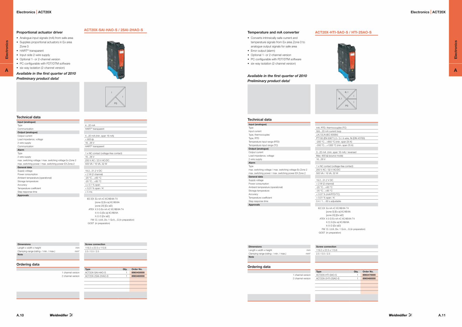
Ele
ctro
nics
A
A.10
Ele
ctro
nics
A
A.11
Electronics | ACT20X Electronics | ACT20X
Proportional actuator driver
• Analogueinputsignals(mA)fromsafearea• SuppliesproportionalactuatorsinExareaZone0
• HART®transparent• Input-side2-wiresupply• Optional1-or2-channelversion• PCconfigurablewithFDT/DTMsoftware• six-wayisolation(2-channelversion)
I
I
PS
Technical dataInput (analogue)Type
Communication
Output (analogue)
Outputcurrent
Loadimpedance,voltage
2-wiresupply
Communication
Alarm
Type
2-wiresupply
max.switchingvoltage/max.switchingvoltageExZone2
max.switchingpower/max.switchingpowerEXZone2
General data
Supplyvoltage
Powerconsumption
Ambienttemperature(operational)
Storagetemperature
Accuracy
Temperaturecoefficient
Stepresponsetime
Approvals
Dimensions
Lengthxwidthxheight mm
Clampingrange(rating-/min./max.) mm2
Note
Ordering data
1channelversion
2channelversion
4...20mA
HART®transparent
4...20mA(min.span16mA)
<600Ω
16...26V
HART®transparent
1xNCcontact(voltage-freecontact)
16...26V
250VAC/23VAC/DC
500VA/16VA,32W
19.2...31.2VDC
<2W(2channel)
-20°C…+60°C
-20°C…+85°C
<±0,1%span
<0,01%span/K
<5ms
IECEX ExnAnCIIC/IIB/IIAT4
[zone0][Exia]IIC/IIB/IIA
[zone20][ExiaD]
ATEX II3GExnAnCIIC/IIB/IIAT4
II(1)G[Exia]IIC/IIB/IIA
II(1)D[ExiaD]
FM Cl.I,II,III,Div.1Gr.A…G(inpreparation)
GOST (inpreparation)
Screw connection119.2x22.5x113.6
2.5/0.5/2.5
Type Qty. Order No.ACT20X-SAI-HAO-S 1 8965450000
ACT20X-2SAI-2HAO-S 1 8965460000
ACT20X-SAI-HAO-S / 2SAI-2HAO-S
Available in the first quarter of 2010Preliminary product data!
Temperature and mA converter
• ConvertsintrinsicallysafecurrentandtemperaturesignalsfromExareaZone0toanalogueoutputsignalsforsafearea
• Erroroutput(alarm)• Optional1-or2-channelversion• PCconfigurablewithFDT/DTMsoftware• six-wayisolation(2-channelversion)
J, I
J, I
I
I
PS
Technical dataInput (analogue)Type
Inputcurrent
Type,thermocouples
Type,RTD
Temperatureinputrange(RTD)
Temperatureinputrange(TC)
Output (analogue)
Outputcurrent
Loadimpedance,voltage
2-wiresupply
Alarm
Type
max.switchingvoltage/max.switchingvoltageExZone2
max.switchingpower/max.switchingpowerEXZone2
General data
Supplyvoltage
Powerconsumption
Ambienttemperature(operational)
Storagetemperature
Accuracy
Temperaturecoefficient
Stepresponsetime
Approvals
Dimensions
Lengthxwidthxheight mm
Clampingrange(rating-/min./max.) mm2
Note
Ordering data
1channelversion
2channelversion
mA,RTD,thermocouples(TC)
0(4)...20mAcurrentloop
J,K,T,E,N(IEC60584)
PT100(EN50671)2-/3-/4-wire,Ni(DIN43760)
-200°C…+850°C(min.span25K)
-200°C…+1300°C(min.span25K)
0...20mA(min.span16mA)/reversed
Max.600Ω(sourcemode)
16...26V
1xNCcontact(voltage-freecontact)
250VAC/32VAC/DC
500VA/16VA,32W
19.2...31.2VDC
<2W(2channel)
-20°C…+60°C
-20°C…+85°C
<0.07%(mA/RTD/TC)
<0.01%span/K
0.4/1….60sadjustable
IECEX ExnAnCIIC/IIB/IIAT4
[zone0][Exia]IIC/IIB/IIA
[zone20][ExiaD]
ATEX II3GExnAnCIIC/IIB/IIAT4
II(1)G[Exia]IIC/IIB/IIA
II(1)D[ExiaD]
FM Cl.I,II,III,Div.1Gr.A…G(inpreparation)
GOST (inpreparation)
Screw connection119.2x22.5x113.6
2.5/0.5/2.5
Type Qty. Order No.ACT20X-HTI-SAO-S 1 8965470000
ACT20X-2HTI-2SAO-S 1 8965480000
ACT20X-HTI-SAO-S / HTI-2SAO-S
Available in the first quarter of 2010Preliminary product data!

Ele
ctro
nics
A
A.12
Ele
ctro
nics
A
A.13
Electronics | ACT20X Electronics | WAVE TTA
Universal signal converter
• ConvertsintrinsicallysafeuniversalsignalsfromExareaZone0toanalogueoutputsignalsforsafearea
• Upskaleordownskalesensorbreak• Erroroutput(alarm)• PCconfigurablewithFDT/DTMsoftware• three-wayisolation
J, I, U
I
PS
Technical dataInput (analogue)Type
Inputcurrent
Inputvoltage
Type,thermocouples
Type,RTD
Temperatureinputrange(RTD)
Temperatureinputrange(TC)
Potentiometerinputrange
CurrentLoopSupply
Output (analogue)
Outputcurrent
Loadimpedance,voltage
2-wiresupply
Alarm
Type
max.switchingvoltage/max.switchingvoltageExZone2
max.switchingpower/max.switchingpowerEXZone2
General data
Supplyvoltage
Powerconsumption
Ambienttemperature(operational)
Storagetemperature
Accuracy
Temperaturecoefficient
Stepresponsetime
Approvals
Dimensions
Lengthxwidthxheight mm
Clampingrange(rating-/min./max.) mm2
Note
Ordering data
1channelversion
mA,V,RTD,thermocouples(TC),Potentiometer
-1…+25mA(min.span16mA)
-20mV…+12VDC(min.span0,8V)
J,K,T,E,N(IEC60584)
PT100(EN50671)2-/3-/4-wire
-200°C…+850°C(min.span25K)
-200°C…+1300°C(min.span25K)
10Ω...10kΩ
16VDC/22mA
0...20mA(min.span16mA)/reversed
Max.600Ω(sourcemode)
16...26V
1xNCcontact(voltage-freecontact)
250VAC/32VAC,30VDC
500VA/64VA,60W
19.2...31.2VDC
<2W
-20°C…+60°C
-20°C…+85°C
<0,1%(V),<0,07(mA/RTD/TC)
<0,01%span/K
0,4/1….60sadjustable
IECEX ExnAnCIIC/IIB/IIAT4
[zone0][Exia]IIC/IIB/IIA
[zone20][ExiaD]
ATEX II3GExnAnCIIC/IIB/IIAT4
II(1)G[Exia]IIC/IIB/IIA
II(1)D[ExiaD]
FM Cl.I,II,III,Div.1Gr.A…G(inpreparation)
GOST (inpreparation)
Screw connection119.2x22.5x113.6
2.5/0.5/2.5
Type Qty. Order No.ACT20X-HUI-SAO-S 1 8965490000
ACT20X-HUI-SAO-S
Available in the first quarter of 2010Preliminary product data!
WAVE TTA
Universalsignalconditionerandtripamplifer
• InputsandoutputsconfigurableviaPC
• Universalinputsignals
• Loop-poweredorpassiveinput
• Pluggableconnectionterminals
• Approvedforexplosion-protectedareasaccordingtoATEXZone2andacc.toULClassIDivision2.
3 Port IsolationAnalogue Inputs
RelayChannel 1RelayChannel 2Output0 ... 11 V /0 ... 22 mA
18-264 V AC/DC supply
+24 V DC
J V, I
PS
V, I
Technical dataInput Type,thermocouple
Type,RTD
Potentiometer/current
Resistance
Frequency
Voltage
Current
CurrentLoopSupply
Outputsignalduringwirebreak/max.
Accuracy
Temperaturecoefficient
Output (analogue)
Outputvoltage
Outputcurrent
Loadresistance,voltage
Current
Signaloutput
Transmitfunction
Output (digital)
Type
Nominalswitchingvoltage
Nominalswitchingcurrent
General data
Nominalvoltage
Powerconsumption
Ambienttemperature(operational)
Storagetemperature
Stepresponsetime
Approvals
Humidity
Insulation coordination
Standards
EMCstandards
Ratedvoltage
Impulsewithstandvoltage
Pollutiondegree
Overvoltagecategory
Clearance&creepagedistance
Insulationvoltage
Dimensions
Clampingrange(rating-/min./max.) mm2
Lengthxwidthxheight mmNote
B,E,J,K,L,N,R,S,T(IEC60584)
PT100,PT1000,(EN60571)Ni100,Ni1000,(JIS1604),Cu10,
Cu25,Cu50,Cu100(DIN43760)2-/3-/4-conductor
100Ω…100kΩ
10Ω…5kΩ
2Hz…100kHz
-200…500mV(min.span4mV),-20…50VDC(min.span0.5V)
-20…50mA(min.span0.4mA)
24VDC/22mA
configurable
<0.1%span(DC,RTD);0.2%span(or1°C)+CJerror
<0.1%/K(DC,RTD);<0.1%FSR/K+CJerror
0.07°C/K(thermocouples)
Canbesetfrom-10…+10V(min.span2.5V)
Canbesetfrom0…20mA(min.span5mA)
>10kΩ@0…10V/>20kΩ@-10…+10V
<700Ω
Directorinverted
Linear,x1/2,x3/2,x5/2oruser-definedcurve(101points)
Relay2xCOfunctions
max.250VAC/max.30VDC
max.2AAC/DC
24...240VAC/DC;24...36VAC/24...50VDC(ATEXzone2)
<3.5W
-40°C…+70°C
-40°C…+85°C
50ms…1s(RTD,mVinputs),110ms…1s(V,mAinputs)
CE;cULus;Cl.IDiv.2/zone2;ATEX/zone2
5…95%nocondensation
EN50178(protectiveseparation)
EN55011,EN61000-6
300V(100VInput/Output)
4kV
2
III
≥5.5mm(1mmInput/Output)
2.5kV
2.5/0.5/2.5
92.4x45x112.4
WAS6 TTA EX / WAZ6 TTA EXTypical functionsTypical functions
I
PS
I, V
Isolator
f, I, V
PS
I, V
Converter
J
PS
I, V
Transmitter
I, V
PS
I, V
Lineariser
J
PS
Trip amplifier
Ordering dataType Qty. Order No.ScrewconnectionWAS6TTAEX 1 8964310000
Tensionclampconn.WAZ6TTAEX 1 8964320000
AccessoriesNote: CBX100USBInterface–7940025031ConnectstheWAVETTAwithaPCforcalibration

Ele
ctro
nics
A
A.14
Ele
ctro
nics
A
A.15
Electronics | ACT20P Bridge
V/I
PS
+
2323 2424
5354
11
2214
12
1321
+
excitation +
sense -sensexcitation -
signal +signal -
sense +
StrainGauge
10...60 V DC
44
41
42
43
mA test point +
mA test point -
0...10 V
I0/4...20 mA
Tare
+
--
-
ACT20P-BRIDGE-SACT20P Bridge
bridgemeasuringtransformerforreadingloadcells
• three-wayisolation• Suppliesmeasuringbridgesupto4x350Ω• Simpletarecalibrationthroughext.sensororPLCinput
• InputandoutputrangesadjustableviaDIPswitches
Technical dataInput Type
Bridgesensitivity
Inputmeasurementrange
Inputresistance
Supplycurrent
Bridgesupplyvoltage
Output
Type
Outputsignal
Loadimpedance,voltage/current
Residualripple
Settings
Measurementcalibration
General data
Supplyvoltage
Powerconsumption
Linearity
Repeataccuracy
Humidity
Temperaturecoefficient
Long-termdrift
Stepresponsetime
Ambienttemperature(operational)/Storagetemperature
Approvals
Insulation coordination
Standards
EMCstandards
Ratedvoltage
Impulsewithstandvoltage
Pollutiondegree
Overvoltagecategory
Insulationvoltage
Dimensions
Clampingrange(rating-/min./max.) mm2
Lengthxwidthxheight mmNote
Ordering data
AccessoriesNote
Resistancemeasuringbridge
1.0mV/Vto5.0mV/V
±10mV/±20mV/±30mV/±50mV(adjustable)
≥87Ω
120mA@10V(=4x350ΩBridgeresistance)
5Vor10V
Voltageandcurrentoutput(configurable)
0…11V/0…22mA(adjustable)
600Ω/1kΩ
<0.05ofsignalrange
Taresettingpossiblewithinthesetmeasurementrange
10…60VDC
3W@24VDC
Typ.±0.05%ofsignalrange
±0.05%ofsignalrange
10…90%(nocondensation)
typ.0.02%/°C
0.1%/10.000h
120ms(10…90%)
0°C…+60°C/-25°C…70°C
CE,cULus
EN61010
EN61326
300Veff4kV(1.2/50µs)
2
III
5.7kV(Input/Output,Input/Supply)Screw connection2.5/0.5/2.5
119.2x22.5x113.6
Type Qty. Order No.ACT20P-BRIDGE-S 1 1067250000

A.16
Ele
ctro
nics
A
A.17
Ele
ctro
nics
A
Electronics | VARITECTOR SPC
unprotected protected
Complete module, direct earthing
Complete module, direct earthing, with remote alert
Complete module, indirect earthing
Complete module, indirect earthing, with remote alert
unprotected protected
unprotected protected
unprotected protected
1
5
2
6
3 4
9 10
7
11
8
12
GND GND
TS
1
5
2
6
3 4
9 10
7
11
8
12
GND GND
TS
X2X1
FAULTOK
1
5
2
6
3 4
9 10
7
11
8
12
GND GND
TS
1
5
2
6
3 4
9 10
7
11
8
12
GND GND
TS
X2X1
FAULTOK
Technical data
Dielectric strength with FG against PE > 500 V
Volume resistivity per path 4.7 Ω
Overstressed fault mode Mode 2
Requirement category acc. to IEC 61643-21 C1; C2; C3; D1
Limiting frequency (-3 dB) at load resistance 750 kHz
Rated discharge current IN (8/20 µs) wire-wire / wire-PE / GND-PE 2.5 kA / 2.5 kA / 2.5 kA
Rated discharge current Imax (8/20 µs) wire-wire / wire-PE / GND-PE 10 kA / 10 kA / 10 kA
Lightning test current, Iimp. (10/350 µs) wire-wire / wire-PE / GND-PE 2.5 kA / 2.5 kA / 2.5 kA
Degree of protection IP20
Type of connection Pluggable in VSPC BASE
Storage temperature -40 °C…+80 °C
Ambient temperature (operational) -40 °C…+70 °C
Rel. humidity 5 %…96 % RH
Dimensions of complete module (arrester + base element) Without telecomm. contact With telecomm. contact (R)
Length x Width x Height mm 90 x 17.8 x 69 98 x 17.8 x 69Note
VSPC 1CL – Protection for one analogue signal
• Optionalmonitoringfunctionwithstatusindicatorandalertfunction
• Pluggablearrester(plug-in/disconnectinterruption-freeand impedance neutral)
• TestablewithV-TESTinstrument• Versionwithnon-earthedPEconnectionforavoiding
potential differences • Usable in accordance with installations standard IEC 62305 • IntegratedPEcontactinbaseelement,safelydischarges
up to 20 kA (8/20 µs) and 2.5 kA (10/350 µs) to PE
Ordering data for baseType Qty. Order No.Base element, direct earthing 1 8924730000
Base element, indirect earthing via spark gap (FG, floating ground) 1 8924290000
Base element, direct earthing with remote alert 1 8951730000
Base element, indirect earthing with remote alert 1 8951740000
Note
Base elements / base to arresters
Electronics | VARITECTOR SPC
VSPC 1CL – arrester / plug-in elements
Ordering data
Rated voltage (DC)
Max. continuous voltage, Uc (DC)Alternating-current strength
Rated current
Surge strength
Signaling contact
Optical function indicator (VSPC R)
Combined pulse UOC
Residual voltage Up
wire-wire / wire-PE / GND-PE
Protection level on output side sym.,
input 1 kV/µs, typ.
input 8/20 µs, typ.
Protection level on output side unsym.,
input 1 kV/µs, typ.
input 8/20 µs, typ.
Ordering data
Without signaling contact / function indicator Type
Order No.
With signaling contact / function indicator Type Order No.
Qty.Note
VSPC 1CL 5 V DC
5 V DC
6,4 V DC
450 mA
UN 250 V AC 0.1 A 1CO at VSPC R
with VSPC CONTROL UNIT
green = OK; red = arrester faulty, replace
10 V / 450 V / 450 V
< 12 V
< 12 V
< 450 V
< 650 V
VSPC 1CL 5VDC 0.5A
8924420000
VSPC 1CL 5VDC 0.5A R8951530000
1 piece
VSPC 1CL 12 V DC
12 V DC
15 V DC
450 mA
UN 250 V AC 0.1 A 1CO at VSPC R
with VSPC CONTROL UNIT
green = OK; red = arrester faulty, replace
20 V / 450 V / 450 V
< 25 V
< 25 V
< 450 V
< 650 V
VSPC 1CL 12VDC 0.5A
8924450000
VSPC 1CL 12VDC 0.5A R8951540000
1 piece
VSPC 1CL 24 V DC
24 V DC
28 V DC
450 mA
UN 250 V AC 0.1 A 1CO at VSPC R
with VSPC CONTROL UNIT
green = OK; red = arrester faulty, replace
40 V / 450 V / 450 V
< 45 V
< 45 V
< 450 V
< 650 V
VSPC 1CL 24VDC 0.5A
8924480000
VSPC 1CL 24VDC 0.5A R8951550000
1 piece
Ordering data
Rated voltage (DC)
Max. continuous voltage, Uc (DC)Alternating-current strength
Rated current
Surge strength
Signaling contact
Optical function indicator (VSPC R)
Combined pulse UOC
Residual voltage Up
wire-wire / wire-PE / GND-PE
Protection level on output side sym.,
input 1 kV/µs, typ.
input 8/20 µs, typ.
Protection level on output side unsym.,
input 1 kV/µs, typ.
input 8/20 µs, typ.
Ordering data
Without signaling contact / function indicator Type
Order No.
With signaling contact / function indicator Type Order No.
Qty.Note
VSPC 1CL 24 V AC
24 V AC / 34 V DC
28 V AC / 39 V DC
450 mA
UN 250 V AC 0.1 A 1CO at VSPC R
with VSPC CONTROL UNIT
green = OK; red = arrester faulty, replace
40 V / 450 V / 450 V
< 60 V
< 60 V
< 450 V
< 650 V
VSPC 1CL 24VAC 0.5A
8924500000
VSPC 1CL 24VAC 0.5A R8951560000
1 piece
VSPC 1CL 48 V AC
48 V AC / 68 V DC
60 V AC / 85 V DC
350 mA
No
green = OK; red = arrester faulty, replace
80 V / 450 V / 450 V
< 85 V
< 85 V
< 450 V
< 650 V
VSPC 1CL 48VAC 0.5A
8924520000
1 piece
VSPC 1CL 60 V AC
60 V AC / 85 V DC
72 V AC / 101 V DC
250 mA
No
green = OK; red = arrester faulty, replace
100 V / 450 V / 450 V
< 100 V
< 100 V
< 450 V
< 650 V
VSPC 1CL 60VAC 0.5A
8924530000
1 piece

A.18
Ele
ctro
nics
A
A.19
Ele
ctro
nics
A
Electronics | VARITECTOR SPC
unprotected protected
Complete module, direct earthing
Complete module, direct earthing, with remote alert
Complete module, indirect earthing
Complete module, indirect earthing, with remote alert
unprotected protected
unprotected protected
unprotected protected
1
5
2
6
3 4
9 10
7
11
8
12
GND GND
TS
1
5
2
6
3 4
9 10
7
11
8
12
GND GND
TS
X2X1
FAULTOK
1
5
2
6
3 4
9 10
7
11
8
12
GND GND
TS
1
5
2
6
3 4
9 10
7
11
8
12
GND GND
TS
X2X1
FAULTOK
Technical data
Dielectric strength with FG against PE > 500 V
Volume resistivity per path 2.2 Ω
Overstressed fault mode Mode 2
Requirement category acc. to IEC 61643-21 C1; C2; C3; D1
Gas discharge tube 230 V
Limiting frequency (-3 dB) at load resistance 750 kHz
Rated discharge current IN (8/20 µs) wire-wire / wire-PE / GND-PE 2.5 kA / 2.5 kA / 2.5 kA
Rated discharge current Imax (8/20 µs) wire-wire / wire-PE / GND-PE 10 kA / 2 x 10 kA / 10kA
Lightning test current, Iimp. (10/350 µs) wire-wire / wire-PE / GND-PE 2.5 kA / 2.5 kA / 2.5 kA
Degree of protection IP20
Type of connection Pluggable in VSPC BASE
Storage temperature -40 °C…+80 °C
Ambient temperature (operational) -40 °C…+70 °C
Rel. humidity 5 %…96 % RH
Dimensions of complete module (arrester + base element) Without telecomm. contact With telecomm. contact (R)
Length x Width x Height mm 90 x 17.8 x 69 98 x 17.8 x 69Note
VSPC 2CL – Protection for two analogue signals
• Optionalmonitoringfunctionwithstatusindicatorandalertfunction
• Pluggablearrester(plug-in/disconnectinterruption-freeand impedance neutral)
• TestablewithV-TESTinstrument• Space-savingdesignfortwoanalogsignalswithsignaling
contact, without additional space requirements • Versionwithnon-earthedPEconnectionforavoiding
potential differences • Usable in accordance with installations standard IEC 62305 • IntegratedPEcontactinbaseelement,safelydischarges
up to 20 kA (8/20 µs) and 2.5 kA (10/350 µs) to PE
Ordering data for baseType Qty. Order No.Base element, direct earthing 1 8924710000
Base element, indirect earthing via spark gap (FG, floating ground) 1 8924270000
Base element, direct earthing with remote alert 1 8951710000
Base element, indirect earthing with remote alert 1 8951720000
Note
Base elements / base to arresters
Electronics | VARITECTOR SPC
VSPC 2CL – arrester / plug-in elements
Ordering data
Rated voltage (DC)
Max. continuous voltage, Uc (DC)Alternating-current strength
Rated current
Surge strength
Signaling contact
Optical function indicator (VSPC R)
Varistor
Suppressor diode
Residual voltage Up
wire-wire / wire-PE / GND-PE
Protection level on output side sym.,
input 1 kV/µs, typ.
input 8/20 µs, typ.
Protection level on output side unsym.,
input 1 kV/µs, typ.
input 8/20 µs, typ.
Ordering data
Without signaling contact / function indicator Type
Order No.
With signaling contact / function indicator Type Order No.
Qty.Note
VSPC 2CL 5 V DC
5 V DC
6.4 V DC
450 mA
UN 250 V AC 0.1 A 1CO at VSPC R
with VSPC CONTROL UNIT
green = OK; red = arrester faulty, replace
7.5 V DC
10 V / 450 V / 450 V
< 12 V
< 12 V
< 450 V
< 650 V
VSPC 2CL 5VDC 0.5A
8924400000
VSPC 2CL 5VDC 0.5A R8951460000
1 piece
VSPC 2CL 12 V DC
12 V DC
15 V DC
450 mA
UN 250 V AC 0.1 A 1CO at VSPC R
with VSPC CONTROL UNIT
green = OK; red = arrester faulty, replace
18 V
20 V / 450 V / 450 V
< 25 V
< 25 V
< 450 V
< 650 V
VSPC 2CL 12VDC 0.5A
8924440000
VSPC 2CL 12VDC 0.5A R8951470000
1 piece
VSPC 2CL 24 V DC
24 V DC
28 V DC
450 mA
UN 250 V AC 0.1 A 1CO at VSPC R
with VSPC CONTROL UNIT
green = OK; red = arrester faulty, replace
33 V
40 V / 450 V / 450 V
< 45 V
< 45 V
< 450 V
< 650 V
VSPC 2CL 24VDC 0.5A
8924470000
VSPC 2CL 24VDC 0.5A R8951480000
1 piece
Ordering data
Rated voltage (DC)
Max. continuous voltage, Uc (DC)Alternating-current strength
Rated current
Surge strength
Signaling contact
Optical function indicator (VSPC R)
Varistor
Suppressor diode
Residual voltage Up
wire-wire / wire-PE / GND-PE
Protection level on output side sym.,
input 1 kV/µs, typ.
input 8/20 µs, typ.
Protection level on output side unsym.,
input 1 kV/µs, typ.
input 8/20 µs, typ.
Ordering data
Without signaling contact / function indicator Type
Order No.
With signaling contact / function indicator Type Order No.
Qty.Note
VSPC 2CL 24 V AC
24 V AC / 34 V DC
28 V AC / 39 V DC
450 mA
UN 250 V AC 0.1 A 1CO at VSPC R
with VSPC CONTROL UNIT
green = OK; red = arrester faulty, replace
33 V
55 V / 450 V / 450 V
< 60 V
< 60 V
< 450 V
< 650 V
VSPC 2CL 24VAC 0.5A
8924490000
VSPC 2CL 24VAC 0.5A R1093400000
1 piece
VSPC 2CL 48 V AC
48 V AC / 68 V DC
60 V AC / 85 V DC
350 mA
No
green = OK; red = arrester faulty, replace
88 V
80 V / 450 V / 450 V
< 85 V
< 85 V
< 450 V
< 650 V
VSPC 2CL 48VAC 0.5A
8951490000
1 piece
VSPC 2CL 60 V AC
60 V AC / 85 V DC
72 V AC / 101 V DC
250 mA
No
green = OK; red = arrester faulty, replace
160 V
10 V / 450 V / 450 V
< 100 V
< 100 V
< 450 V
< 650 V
VSPC 2CL 60VAC 0.5A
8951500000
1 piece

A.20
Ele
ctro
nics
A
A.21
Ele
ctro
nics
A
Electronics | VARITECTOR SPC
unprotected protected
Complete module, direct earthing
Complete module, direct earthing, with remote alert
Complete module, indirect earthing
Complete module, indirect earthing, with remote alert
unprotected protected
unprotected protected
unprotected protected
1
5
2
6
3 4
9 10
7
11
8
12
GND GND
TS
1
5
2
6
3 4
9 10
7
11
8
12
GND GND
TS
X2X1
FAULTOK
1
5
2
6
3 4
9 10
7
11
8
12
GND GND
TS
1
5
2
6
3 4
9 10
7
11
8
12
GND GND
TS
X2X1
FAULTOK
Technical data
Dielectric strength with FG against PE > 500 V
Rated current 450 mA
Volume resistivity per path 2.2 Ω
Overstressed fault mode Mode 2
Requirement category acc. to IEC 61643-21 C1; C2; C3; D1
Limiting frequency (-3 dB) at load resistance 200 MHz
Rated discharge current IN (8/20 µs) wire-wire / wire-PE / GND-PE 2.5 kA / 2.5 kA / 2.5 kA
Rated discharge current Imax (8/20 µs) wire-wire / wire-PE / GND-PE 10 kA / 2 x 10 kA / 10kA
Lightning test current, Iimp. (10/350 µs) wire-wire / wire-PE / GND-PE 2.5 kA / 2.5 kA / 2.5 kA
Degree of protection IP20
Type of connection Pluggable in VSPC BASE
Storage temperature -40 °C…+80 °C
Ambient temperature (operational) -40 °C…+70 °C
Rel. humidity 5 %…96 % RH
Dimensions of complete module (arrester + base element) Without telecomm. contact With telecomm. contact (R)
Length x Width x Height mm 90 x 17.8 x 69 98 x 17.8 x 69Note
VSPC 2CL HF – for high transmission rates without signal delays
• Optionalmonitoringfunctionwithstatusindicatorandalertfunction
• Pluggablearrester(plug-in/disconnectinterruption-freeand impedance neutral)
• TestablewithV-TESTinstrument• Space-savingdesignwithoptionalsignalingcontact,
without additional space requirements • Hightransmissionrateswithlowattenuationvalues• Usable in accordance with installations standard IEC 62305 • IntegratedPEcontactinbaseelement,safelydischarges
up to 20 kA (8/20 µs) and 2.5 kA (10/350 µs) to PE
Ordering data for baseType Qty. Order No.Base element, direct earthing 1 8924710000
Base element, indirect earthing via spark gap (FG, floating ground) 1 8924270000
Base element, direct earthing with remote alert 1 8951710000
Base element, indirect earthing with remote alert 1 8951720000
Note
Base elements / base to arresters
Electronics | VARITECTOR SPC
VSPC 2CL HF – arrester / plug-in elements
Ordering data
Rated voltage (DC)
Max. continuous voltage, Uc (DC)Alternating-current strength
Surge strength
Signaling contact
Optical function indicator (VSPC R)
Residual voltage Up
wire-wire / wire-PE / GND-PE
Protection level on output side sym.,
input 1 kV/µs, typ.
input 8/20 µs, typ.
Protection level on output side unsym.,
input 1 kV/µs, typ.
input 8/20 µs, typ.
Ordering data
Without signaling contact / function indicator Type
Order No.
With signaling contact / function indicator Type Order No.
Qty.Note
VSPC 2CL HF 5 V DC
5 V DC
6.4 V DC
UN 250 V AC 0.1 A 1CO at VSPC R
with VSPC CONTROL UNIT
green = OK; red = arrester faulty, replace
10 V / 450 V / 450 V
< 12 V
< 12 V
< 450 V
< 650 V
VSPC 2CL HF 5VDC
8924430000
VSPC 2CL HF 5VDC R8951680000
1 piece
VSPC 2CL HF 12 V DC
12 V DC
15 V DC
UN 250 V AC 0.1 A 1CO at VSPC R
with VSPC CONTROL UNIT
green = OK; red = arrester faulty, replace
20 V / 450 V / 450 V
< 25 V
< 25 V
< 450 V
< 650 V
VSPC 2CL HF 12VDC
8924460000
VSPC 2CL HF 12VDC R8951690000
1 piece
VSPC 2CL HF 24 V DC
24 V DC
28 V DC
UN 250 V AC 0.1 A 1CO at VSPC R
with VSPC CONTROL UNIT
green = OK; red = arrester faulty, replace
40 V / 450 V / 450 V
< 45 V
< 45 V
< 450 V
< 650 V
VSPC 2CL HF 24VDC
8924510000
VSPC 2CLHF 24VDC R8951700000
1 piece

A.22
Ele
ctro
nics
A
A.23
Ele
ctro
nics
A
Electronics | VARITECTOR SPC
Complete module, direct earthing
Complete module, indirect earthing
protectedunprotected
protectedunprotected
1
5
2
6
3 4
9 10
7
11
8
12
GND GND
TSTS
FAULTFAULT 24 V~24 V~
�
U
�
U
1
5
2
6
3 4
9 10
7
11
8
12
GND GND
TSTS
FAULTFAULT 24 V~24 V~
�
U
�
U
VSPC 1CL PW – combinations of current loop signal and circuit breaker
• Optionalmonitoringfunctionwithstatusindicator• Pluggablearrester(plug-in/disconnectinterruption-free
and impedance neutral)• Usable in accordance with installations standard IEC 62305 • IntegratedPEcontactinbaseelement,safelydischarges
up to 20 kA (8/20 µs) and 2.5 kA (10/350 µs) to PE
Technical data
Rated voltage (DC) 24 V AC / 34 V DC
Max. continuous voltage, Uc (DC) 28 V AC / 39 V DC
Dielectric strength with FG against PE > 500 V
Rated current 450 mA / 26 A for PW
Volume resistivity per path 4.7 Ω
Overstressed fault mode Mode 2
Requirement category acc. to IEC 61643-21 C1; C2; C3; D1
Optical function indicator green = OK; red = arrester faulty, replace
Optical function indicator (VSPC R) green = OK; red = arrester faulty, replace
Rated voltage (AC/DC) 24 V AC / 33 V DC
Requirement category acc. to IEC 61643-1 Class III
Combined pulse UOC 4 kV
Limiting frequency (-3 dB) at load resistance 750 kHz
Rated discharge current IN (8/20 µs) wire-wire / wire-PE / GND-PE 2.5 kA / 2.5 kA / 2.5 kA
Rated discharge current Imax (8/20 µs) wire-wire / wire-PE / GND-PE 10 kA / 10 kA / 10 kA
Lightning test current, Iimp. (10/350 µs) wire-wire / wire-PE / GND-PE 2.5 kA / 2.5 kA / 2.5 kA
Residual voltage Up wire-wire / wire-PE / GND-PE 40 V / 450 V / 450 V
Protection level on output side sym., input 1 kV/µs, typ. < 60 V
Protection level on output side sym., input 8/20 µs, typ. < 60 V
Protection level on output side unsym., input 1 kV/µs, typ. < 450 V
Protection level on output side unsym., input 8/20 µs, typ. < 650 V
Degree of protection IP20
Type of connection Pluggable in VSPC BASE
Storage temperature -40 °C…+80 °C
Ambient temperature (operational) -40 °C…+70 °C
Rel. humidity 5 %…96 % RH
Dimensions of complete module (arrester + base element) Without telecomm. contact With telecomm. contact (R)
Length x Width x Height mm 90 x 17.8 x 69 98 x 17.8 x 69Note
Ordering data for baseType Qty. Order No.Base element, direct earthing 1 1070230000
Base element, indirect earthing via spark gap (FG, floating ground) 1 1105700000
Note
Base elements / base to arresters
VSPC 1CL PW 24 V
VSPC 1CL PW 24V 0.5A
8951510000
1 piece
Ordering data
Without signaling contact / function indicator Type
Order No.
Qty.Note
Electronics | VARITECTOR SPC
VSPC 1CL PW – arrester / plug-in elements

A.24
Ele
ctro
nics
A
A.25
Ele
ctro
nics
A
Electronics | VARITECTOR SPC
unprotected protected
Complete module, direct earthing
Complete module, direct earthing, with remote alert
Complete module, indirect earthing
Complete module, indirect earthing, with remote alert
unprotected protected
unprotected protected
unprotected protected
1
5
2
6
3 4
9 10
7
11
8
12
GND GND
TS
1
5
2
6
3 4
9 10
7
11
8
12
GND GND
TS
X2X1
FAULTOK
1
5
2
6
3 4
9 10
7
11
8
12
GND GND
TS
1
5
2
6
3 4
9 10
7
11
8
12
GND GND
TS
X2X1
FAULTOK
Technical data
Dielectric strength with FG against PE > 500 V
Volume resistivity per path 4.7 Ω
Overstressed fault mode Mode 2
Requirement category acc. to IEC 61643-21 C1; C2; C3; D1
Limiting frequency (-3 dB) at load resistance 750 kHz
Rated discharge current IN (8/20 µs) wire-wire / wire-PE / GND-PE 2.5 kA / 2.5 kA / 2.5 kA
Rated discharge current Imax (8/20 µs) wire-wire / wire-PE / GND-PE 10 kA / 10 kA / 10kA
Lightning test current, Iimp. (10/350 µs) wire-wire / wire-PE / GND-PE 2.5 kA / 2.5 kA / 2.5 kA
Degree of protection IP20
Type of connection Pluggable in VSPC BASE
Storage temperature -40 °C…+80 °C
Ambient temperature (operational) -40 °C…+70 °C
Rel. humidity 5 %…96 % RH
Dimensions of complete module (arrester + base element) Without telecomm. contact With telecomm. contact (R)
Length x Width x Height mm 90 x 17.8 x 69 98 x 17.8 x 69Note
VSPC 2SL – Protection for two binary signals
• Optionalmonitoringfunctionwithstatusindicatorandalertfunction
• Pluggablearrester(plug-in/disconnectinterruption-freeand impedance neutral)
• TestablewithV-TESTinstrument• Versionwithnon-earthedPEconnectionforavoiding
potential differences• Usable in accordance with installations standard IEC 62305 • IntegratedPEcontactinbaseelement,safelydischarges
up to 20 kA (8/20 µs) and 2.5 kA (10/350 µs) to PE
Ordering data for baseType Qty. Order No.Base element, direct earthing 1 8924720000
Base element, indirect earthing via spark gap (FG, floating ground) 1 8924280000
Base element, direct earthing with remote alert 1 8951770000
Base element, indirect earthing with remote alert 1 8951780000
Note
Base elements / base to arresters
Electronics | VARITECTOR SPC
VSPC 2SL – arrester / plug-in elements
Ordering data
Rated voltage UN
Max. continuous voltage UC
Signaling contact
Optical function indicator (VSPC R)
Residual voltage Up
wire-wire / wire-PE / GND-PE
Protection level on output side sym.,
input 1 kV/µs, typ.
input 8/20 µs, typ.
Protection level on output side unsym.,
input 1 kV/µs, typ.
input 8/20 µs, typ.
Rated current
Ordering data
Without signaling contact / function indicator Type
Order No.
With signaling contact / function indicator Type Order No.
Qty.Note
VSPC 2SL 5 V DC
5 V DC
6.4 V DC
UN 250 V AC 0.1 A 1CO at VSPC R
with VSPC CONTROL UNIT
green = OK; red = arrester faulty,
replace
- / 10 V / 450 V
< 25 V
< 25 V
< 12 V
< 25 V
300 mA
VSPC 2SL 5VDC 0.5A
8924210000
VSPC 2SL 5VDC 0.5A R8951610000
1 piece
VSPC 2SL 12 V DC
12 V DC
15 V DC
UN 250 V AC 0.1 A 1CO at VSPC R
with VSPC CONTROL UNIT
green = OK; red = arrester faulty,
replace
- / 20 V / 450 V
< 45 V
< 45 V
< 25 V
< 35 V
300 mA
VSPC 2SL 12VDC 0.5A
8924230000
VSPC 2SL 12VDC 0.5A R8951620000
1 piece
VSPC 2SL 12 V AC
12 V AC
13.2 V AC
No
green = OK; red = arrester faulty,
replace
- / 20 V / 450 V
< 55 V
< 55 V
< 30 V
< 40 V
300 mA
VSPC 2SL 12VAC 0.5A
8924250000
1 piece
VSPC 2SL 24 V DC
24 V DC
28 V DC
UN 250 V AC 0.1 A 1CO at VSPC R
with VSPC CONTROL UNIT
green = OK; red = arrester faulty,
replace
- / 40 V / 450 V
< 80 V
< 80 V
< 40 V
< 50 V
300 mA
VSPC 2SL 24VDC 0.5A
8924330000
VSPC 2SL 24VDC 0.5A R8951630000
1 piece
Ordering data
Rated voltage UN
Max. continuous voltage UC
Signaling contact
Optical function indicator (VSPC R)
Residual voltage Up
wire-wire / wire-PE / GND-PE
Protection level on output side sym.,
input 1 kV/µs, typ.
input 8/20 µs, typ.
Protection level on output side unsym.,
input 1 kV/µs, typ.
input 8/20 µs, typ.
Rated current
Ordering data
Without signaling contact / function indicator Type
Order No.
With signaling contact / function indicator Type Order No.
Qty.Note
VSPC 2SL 24 V AC
24 V AC / 34 V DC
28 V AC / 39 V DC
UN 250 V AC 0.1 A 1CO at VSPC R
with VSPC CONTROL UNIT
green = OK; red = arrester faulty,
replace
- / 40 V / 450 V
< 110 V
< 80 V
< 60 V
< 65 V
300 mA
VSPC 2SL 24VAC 0.5A
8924350000
VSPC 2SL 24VAC 0.5A R8951640000
1 piece
VSPC 2SL 48 V AC
48 V AC / 68 V DC
60 V AC / 85 V DC
No
green = OK; red = arrester faulty,
replace
- / 80 V / 450 V
< 210 V
< 80 V
< 85 V
< 125 V
250 mA
VSPC 2SL 48VAC 0.5A
8924370000
1 piece
VSPC 2SL 60 V AC
60 V AC / 85 V DC
72 V AC / 101 V DC
No
green = OK; red = arrester faulty,
replace
- / 100 V / 450 V
< 280 V
< 80 V
< 100 V
< 165 V
200 mA
VSPC 2SL 60VAC 0.5A
8924390000
1 piece

A.26
Ele
ctro
nics
A
A.27
Ele
ctro
nics
A
Electronics | VARITECTOR SPC
unprotected protected
Complete module, direct earthing
Complete module, direct earthing, with remote alert
Complete module, indirect earthing
Complete module, indirect earthing, with remote alert
unprotected protected
unprotected protected
unprotected protected
1
5
2
6
3 4
9 10
7
11
8
12
GND GND
TS
1
5
2
6
3 4
9 10
7
11
8
12
GND GND
TS
X2X1
FAULTFAULTOKOK
1
5
2
6
3 4
9 10
7
11
8
12
GND GND
TS
1
5
2
6
3 4
9 10
7
11
8
12
GND GND
TS
X2X1
FAULTFAULTOKOK
Technical data
Volume resistivity per path 4.7 Ω
Overstressed fault mode Mode 2
Requirement category acc. to IEC 61643-21 C1; C2; C3; D1
Limiting frequency (-3 dB) at load resistance 750 kHz
Rated discharge current IN (8/20 µs) wire-wire / wire-PE / GND-PE 2.5 kA / 2.5 kA / 2.5 kA
Rated discharge current Imax (8/20 µs) wire-wire / wire-PE / GND-PE 10 kA / 10 kA / 10 kA
Lightning test current, Iimp. (10/350 µs) wire-wire / wire-PE / GND-PE 2.5 kA / 2.5 kA / 2.5 kA
Degree of protection IP20
Type of connection Pluggable in VSPC BASE
Storage temperature -40 °C … +80 °C
Ambient temperature (operational) -40 °C … +70 °C
Rel. humidity 5 % … 96 % RH
Dimensions of complete module (arrester + base element) Without telecomm. contact With telecomm. contact (R)
Length x Width x Height mm 90 x 17.8 x 69 98 x 17.8 x 69Note
VSPC 4SL – Protection for four binary signals
• Optionalmonitoringfunctionwithstatusindicatorandalertfunction
• Pluggablearrester(plug-in/disconnectinterruption-freeand impedance neutral)
• TestablewithV-TESTinstrument• Space-savingdesignforfourbinarysignalswithsignaling
contact, without additional space requirements • Versionwithnon-earthedPEconnectionforavoiding
potential differences• Usable in accordance with installations standard IEC 62305 • IntegratedPEcontactinbaseelement,safelydischarges
up to 20 kA (8/20 µs) and 2.5 kA (10/350 µs) to PE
Ordering data for baseType Qty. Order No.Base element, direct earthing 1 8924700000
Base element, indirect earthing via spark gap (FG, floating ground) 1 8924260000
Base element, direct earthing with remote alert 1 8951750000
Base element, indirect earthing with remote alert 1 8951760000
Note
Base elements / base to arresters
Electronics | VARITECTOR SPC
VSPC 4SL – arrester / plug-in elements
Ordering data
Rated voltage UN
Max. continuous voltage UC
Signaling contact
Optical function indicator (VSPC R)
Residual voltage Up
wire-wire / wire-PE / GND-PE
Protection level on output side sym.,
input 1 kV/µs, typ.
input 8/20 µs, typ.
Protection level on output side unsym.,
input 1 kV/µs, typ.
input 8/20 µs, typ.
Rated current
Ordering data
Without signaling contact / function indicator Type
Order No.
With signaling contact / function indicator Type Order No.
Qty.Note
VSPC 4SL 5 V DC
5 V DC
6.4 V DC
UN 250 V AC 0.1 A 1CO at VSPC R
with VSPC CONTROL UNIT
green = OK; red = arrester faulty,
replace
- / 10 V / 450 V
< 25 V
< 25 V
< 12 V
< 25 V
350 mA
VSPC 4SL 5VDC 0.5A
8924200000
VSPC 4SL 5VDC 0.5A R8951570000
1 piece
VSPC 4SL 12 V DC
12 V DC
15 V DC
UN 250 V AC 0.1 A 1CO at VSPC R
with VSPC CONTROL UNIT
green = OK; red = arrester faulty,
replace
- / 20 V / 450 V
< 45 V
< 45 V
< 25 V
< 35 V
300 mA
VSPC 4SL 12VDC 0.5A
8924220000
VSPC 4SL 12VDC 0.5A R8951580000
1 piece
VSPC 4SL 12 V AC
12 V AC / 16 V DC
13.2 V AC / 18 V DC
No
green = OK; red = arrester faulty,
replace
- / 30 V / 450 V
< 55 V
< 55 V
< 30 V
< 40 V
300 mA
VSPC 4SL 12VAC 0.5A
8924240000
1 piece
VSPC 4SL 24 V DC
24 V DC
28 V DC
UN 250 V AC 0.1 A 1CO at VSPC R
with VSPC CONTROL UNIT
green = OK; red = arrester faulty,
replace
- / 38 V / 450 V
< 80 V
< 80 V
< 40 V
< 50 V
300 mA
VSPC 4SL 24VDC 0.5A
8924320000
VSPC 4SL 24VDC 0.5A R8951590000
1 piece
Ordering data
Rated voltage UN
Max. continuous voltage UC
Signaling contact
Optical function indicator (VSPC R)
Residual voltage Up
wire-wire / wire-PE / GND-PE
Protection level on output side sym.,
input 1 kV/µs, typ.
input 8/20 µs, typ.
Protection level on output side unsym.,
input 1 kV/µs, typ.
input 8/20 µs, typ.
Rated current
Ordering data
Without signaling contact / function indicator Type
Order No.
With signaling contact / function indicator Type Order No.
Qty.Note
VSPC 4SL 24 V AC
24 V AC / 34 V DC
28 V AC / 39 V DC
UN 250 V AC 0.1 A 1CO at VSPC R
with VSPC CONTROL UNIT
green = OK; red = arrester faulty,
replace
- / 45 V / 450 V
< 110 V
< 80 V
< 60 V
< 65 V
300 mA
VSPC 4SL 24VAC 0.5A
8924340000
VSPC 4SL 24VAC 0.5A R8951600000
1 piece
VSPC 4SL 48 V AC
48 V AC / 68 V DC
60 V AC / 85 V DC
No
green = OK; red = arrester faulty,
replace
- / 80 V / 450 V
< 210 V
< 80 V
< 85 V
< 125 V
250 mA
VSPC 4SL 48VAC 0.5A
8924360000
1 piece
VSPC 4SL 60 V AC
60 V AC / 85 V DC
72 V AC / 101 V DC
No
green = OK; red = arrester faulty,
replace
- / 100 V / 450 V
< 280 V
< 80 V
< 100 V
< 165 V
200 mA
VSPC 4SL 60VAC 0.5A
8924380000
1 piece

A.28
Ele
ctro
nics
A
A.29
Ele
ctro
nics
A
Electronics | VARITECTOR SPC
Complete module, direct earthing
Complete module, indirect earthing
protectedunprotected
protectedunprotected
1
5
2
6
3 4
9 10
7
11
8
12
GND GND
TS
1
5
2
6
3 4
9 10
7
11
8
12
GND GND
TSTS
VSPC 4SL WIRE – 3/4 conductor, measurement
• Pluggablearrester(plug-in/disconnectinterruption-freeand impedance neutral)
• Protectionofmeasuringbridgesignals• TestablewithV-TESTinstrument• Usable in accordance with installations standard IEC 62305 • IntegratedPEcontactinbaseelement,safelydischarges
up to 20 kA (8/20 µs) and 2.5 kA (10/350 µs) to PE
Technical data
Rated current 300 mA
Volume resistivity per path 0.2 Ω
Overstressed fault mode Mode 2
Requirement category acc. to IEC 61643-21 C1; C2; C3; D1
Limiting frequency (-3 dB) at load resistance 750 kHz
Rated discharge current IN (8/20 µs) wire-wire / wire-PE / GND-PE 2.5 kA / 2.5 kA / 2.5 kA
Rated discharge current Imax (8/20 µs) wire-wire / wire-PE / GND-PE 10 kA / 10 kA / 10 kA
Lightning test current, Iimp. (10/350 µs) wire-wire / wire-PE / GND-PE 2.5 kA / 2.5 kA / 2.5 kA
Degree of protection IP20
Type of connection Pluggable in VSPC BASE
Storage temperature -40 °C…+80 °C
Ambient temperature (operational) -40 °C...+70 °C
Rel. humidity 5 %...96 % RH
Dimensions of complete module (arrester + base element) Without telecomm. contact With telecomm. contact (R)
Length x Width x Height mm 90 x 17.8 x 69 98 x 17.8 x 69Note
Ordering data for baseType Qty. Order No.Base element, direct earthing 1 8924740000
Base element, indirect earthing via spark gap (FG, floating ground) 1 8924300000
Note
Base elements / base to arresters
VSPC 3/4WIRE 5 V DC
3 V DC
6.4 V DC
20 V / 10 V / 450 V
< 35 V
< 35 V
< 250 V
< 650 V
VSPC 3/4WIRE 5VDC
8924540000
1 piece
VSPC 3/4WIRE 24 V DC
24 V DC
28 V DC
80 V / 38 V / 450 V
< 50 V
< 50 V
< 270 V
< 650 V
VSPC 3/4WIRE 24VDC
8924550000
1 piece
Ordering data
Rated voltage (DC)
Max. continuous voltage, Uc (DC)
Residual voltage Up wire-wire / wire-PE / GND-PE
Protection level on output side sym., input 1 kV/µs, typ.
input 8/20 µs, typ.
Protection level on output side unsym., input 1 kV/µs, typ.
input 8/20 µs, typ.
Ordering data
Without signaling contact / Type
function indicator Order No.
Qty.Note
Electronics | VARITECTOR SPC
VSPC 4SL WIRE – arrester / plug-in elements

A.30
Ele
ctro
nics
A
A.31
Ele
ctro
nics
A
Electronics | VARITECTOR SPC
Technical data
Dielectric strength with FG against PE > 500 V
Volume resistivity per path < 0.1 Ω
Overstressed fault mode Mode 2
Degree of protection IP20
Type of connection Pluggable in VSPC BASE
Storage temperature -40 °C…+80 °C
Ambient temperature (operational) -40 °C…+70 °C
Rel. humidity 5 %…96 % RH
Dimensions of complete module (arrester + base element) Without telecomm. contact With telecomm. contact (R)
Length x Width x Height mm 90 x 17.8 x 69 98 x 17.8 x 69Note
VSPC GDT – with components
Pluggable arrester with components: GDT• Pluggablearrester(plug-in/disconnectinterruption-free
and impedance neutral)• TestablewithV-TESTinstrument• IntegratedPEcontactinbaseelement,safelydischarges
up to 20 kA (8/20 µs) and 2.5 kA (10/350 µs) to PE
Ordering data for baseType Qty. Order No.Base element, direct earthing 1 8924740000
Base element, indirect earthing via spark gap (FG, floating ground) 1 8924300000
Note
Base elements / base to arresters
Complete module, direct earthing
Complete module, indirect earthing
protectedunprotected
protectedunprotected
1
5
2
6
3 4
9 10
7
11
8
12
GND GND
TS
1
5
2
6
3 4
9 10
7
11
8
12
GND GND
TS
Electronics | VARITECTOR SPC
VSPC GDT – arrester / plug-in elements
Ordering data
Rated voltage (DC)
Max. continuous voltage, Uc (DC)Signaling contact
Rated current
Limiting frequency (-3 dB) at load resistance
Rated discharge current IN (8/20 µs)
wire-wire / wire-PE / GND-PE
Rated discharge current Imax (8/20 µs)
wire-wire / wire-PE / GND-PE
Lightning test current, Iimp. (10/350 µs)
wire-wire / wire-PE / GND-PE
Combined pulse UOC
Residual voltage Up
wire-wire / wire-PE / GND-PE
Protection level on output side sym.,
input 1 kV/µs, typ.
input 8/20 µs, typ.
Requirement category acc. to IEC 61643-21
Ordering data
Without signaling contact / function indicator Type
Order No.
With signaling contact / function indicator Type Order No.
Qty.Note
VSPC GDT 2CH 90 V
48 V AC / 68 V DC
50 V AC / 72 V DC
No
450 mA
2 MHz
2 x 2.5 kA / - / 2.5 kA
2 x 10 kA / - / 10 kA
2 x 0.2 kA / - / 0.2 kA
450 V / - / -
< 450 V
< 450 V
C1; C2; C3; D1
VSPC GDT 2ch 90V20kA
8924570000
1 piece
VSPC GDT 2CH 230 V
230 V AC / 350 V DC
420 V AC / 600 V DC
No
450 mA
2 MHz
2 x 2.5 kA / - / 2.5 kA
2 x 10 kA / - / 10 kA
2 x 0.2 kA / - / 0.2 kA
450 V / - / -
< 450 V
< 650 V
C1; C2; C3; D1
VSPC GDT 2ch230V20kA
8924590000
1 piece

A.32
Ele
ctro
nics
A
A.33
Ele
ctro
nics
A
Electronics | VARITECTOR SPC
Technical data
Dielectric strength with FG against PE > 500 V
Volume resistivity per path < 0.1 Ω
Overstressed fault mode Mode 2
Degree of protection IP20
Type of connection Pluggable in VSPC BASE
Storage temperature -40 °C…+80 °C
Ambient temperature (operational) -40 °C…+70 °C
Rel. humidity 5 %…96 % RH
Dimensions of complete module (arrester + base element) Without telecomm. contact With telecomm. contact (R)
Length x Width x Height mm 90 x 17.8 x 69 98 x 17.8 x 69Note
VSPC MOV – with components
Pluggable arrester with components: MOV• Optionalmonitoringfunctionwithstatusdisplayandalert
function for MOV components• Pluggablearrester(plug-in/disconnectinterruption-free
and impedance neutral)• TestablewithV-TESTinstrument• IntegratedPEcontactinbaseelement,safelydischarges
up to 20 kA (8/20 µs) and 2.5 kA (10/350 µs) to PE
Ordering data for baseType Qty. Order No.Base element, direct earthing 1 8924740000
Base element, indirect earthing via spark gap (FG, floating ground) 1 8924300000
Base element, direct earthing with remote alert 1 8951790000
Base element, indirect earthing with remote alert 1 8951800000
Note
Base elements / base to arresters
unprotected protected
Complete module, direct earthing
Complete module, direct earthing, with remote alert
Complete module, indirect earthing
Complete module, indirect earthing, with remote alert
unprotected protected
unprotected protected
unprotected protected
1
5
2
6
3 4
9 10
7
11
8
12
GND GND
TS
U
U
�
�
1
5
2
6
3 4
9 10
7
11
8
12
GND GND
TS
U
U
X2X1
FAULTOK
�
�
1
5
2
6
3 4
9 10
7
11
8
12
GND GND
TS
U
U
�
�
1
5
2
6
3 4
9 10
7
11
8
12
GND GND
TS
U
U
X2X1
FAULTOK
�
�
Electronics | VARITECTOR SPC
VSPC MOV – arrester / plug-in elements
Ordering data
Rated voltage (DC)
Max. continuous voltage, Uc (DC)Signaling contact
Optical function indicator (VSPC R)
Rated current
Limiting frequency (-3 dB) at load resistance
Rated discharge current IN (8/20 µs)
wire-wire / wire-PE / GND-PE
Rated discharge current Imax (8/20 µs)
wire-wire / wire-PE / GND-PE
Lightning test current, Iimp. (10/350 µs)
wire-wire / wire-PE / GND-PE
Combined pulse UOC
Residual voltage Up
wire-wire / wire-PE / GND-PE
Protection level on output side sym.,
input 1 kV/µs, typ.
input 8/20 µs, typ.
Requirement category acc. to IEC 61643-21
Ordering data
Without signaling contact / function indicator Type
Order No.
With signaling contact / function indicator Type Order No.
Qty.Note
VSPC MOV 2CH 24 V
24 V AC
30 V AC / 42 V DC
UN 250 V AC 0.1 A 1CO at VSPC R
with VSPC CONTROL UNIT
green = OK; red = arrester faulty, replace
10 A
1 MHz
0.2 kA / - / 2.5 kA
2 kA / - / 2 kA
0.2 kA / - / 2.5 kA
80 V / - / -
< 80 V
< 95 V
C1; C2; C3
VSPC MOV 2CH 24V 8kA
8924600000
VSPC MOV 2CH 24V 8kA R8951650000
1 piece
VSPC MOV 2CH 230 V
230 V AC
275 V AC / 385 V DC
UN 250 V AC 0.1 A 1CO at VSPC R
with VSPC CONTROL UNIT
green = OK; red = arrester faulty, replace
10 A
1 MHz
1.5 kA / - / 2.5 kA
8 kA / - / 8 kA
0.2 kA / - / 2.5 kA
4 kV
600 V / - / -
< 600 V
< 700 V
C1; C2; C3
VSPC MOV 2ch 230V8kA
8924610000
VSPC MOV 2ch 230V8kA R8951660000
1 piece

A.34
Ele
ctro
nics
A
A.35
Ele
ctro
nics
A
Electronics | VARITECTOR SPC
unprotected protected
Complete module VSPC TAZ 2ch direct earthing
Complete module VSPC TAZ 2ch indirect earthing
Complete module VSPC TAZ 4ch direct earthing
Complete module VSPC TAZ 4ch indirect earthing
unprotected protected
unprotected protected
unprotected protected
1
5
2
6
3 4
9 10
7
11
8
12
GND GND
TS
1
5
2
6
3 4
9 10
7
11
8
12
GND GND
TS
1
5
2
6
3 4
9 10
7
11
8
12
GND GND
TS
1
5
2
6
3 4
9 10
7
11
8
12
GND GND
TS
VSPC TAZ – components
Pluggable arrester with components: TAZ• Pluggablearrester(plug-in/disconnectinterruption-free
and impedance neutral)• TestablewithV-TESTinstrument• IntegratedPEcontactinbaseelement,safelydischarges
up to 20 kA (8/20 µs) and 2.5 kA (10/350 µs) to PE
Technical data
Dielectric strength with FG against PE > 500 V
Rated current 10 A
Volume resistivity per path < 0.1 Ω
Overstressed fault mode Mode 2
Requirement category acc. to IEC 61643-21 C1; C2
Degree of protection IP20
Type of connection Pluggable in VSPC BASE
Storage temperature -40 °C…+80 °C
Ambient temperature (operational) -40 °C…+70 °C
Rel. humidity 5 %…96 % RH
Dimensions of complete module (arrester + base element) Without telecomm. contact With telecomm. contact (R)
Length x Width x Height mm 90 x 17.8 x 69 98 x 17.8 x 69Note
Ordering data for baseType Qty. Order No.Base element, direct earthing 1 8924740000
Base element, indirect earthing via spark gap (FG, floating ground) 1 8924300000
Note
Base elements / base to arresters
VSPC TAZ 2 CH 24 V AC
24 V AC / 34 V DC
28 V AC / 39 V DC
1 MHz
0.05 kA / - / -
0.1 kA / - / -
55 V / - / -
< 50 V
< 55 V
VSPC TAZ 2ch24Vac 0.1kA
8924640000
1 piece
VSPC TAZ 4 CH 24 V
24 V AC / 34 V DC
28 V AC / 39 V DC
1 MHz
- / 0.05 kA / -
- / 0.1 kA / -
- / 55 V / -
< 50 V
< 55 V
VSPC TAZ 4ch24V 0.1kA
8924650000
1 piece
Ordering data
Rated voltage (DC)
Max. continuous voltage, Uc (DC)
Limiting frequency (-3 dB) at load resistance
Rated discharge current IN (8/20 µs) wire-wire / wire-PE / GND-PE
Rated discharge current Imax (8/20 µs) wire-wire / wire-PE / GND-PE
Combined pulse UOC
Residual voltage Up wire-wire / wire-PE / GND-PE
Protection level on output side sym., input 1 kV/µs, typ.
input 8/20 µs, typ.
Ordering data
Without signaling contact / Type
function indicator Order No.
Qty.Note
Electronics | VARITECTOR SPC
VSPC TAZ – arrester / plug-in elements

A.36
Ele
ctro
nics
A
A.37
Ele
ctro
nics
A
VSPC TELE UK0
for the Uk0/S0 interface in telecommunication• Pluggablearrester(plug-in/disconnectinterruption-free
and impedance neutral)• Lowresidualvoltage• 2-wireinputinterface–Uk0
• TestablewithV-TESTinstrument• IntegratedPEcontactinbaseelement,safelydischarges
up to 20 kA (8/20 µs) and 2.5 kA (10/350 µs) to PE
Technical data
Dielectric strength with FG against PE > 500 V
Rated current 450 mA
Volume resistivity per path 2.2 Ω
Overstressed fault mode Mode 2
Requirement category acc. to IEC 61643-21 C1; C2; C3; D1
Combined pulse UOC 4 kV
Limiting frequency (-3 dB) at load resistance 200 MHz
Rated discharge current IN (8/20 µs) wire-wire / wire-PE / GND-PE 2.5 kA / 2.5 kA / 2.5 kA
Rated discharge current Imax (8/20 µs) wire-wire / wire-PE / GND-PE 10 kA / 2 x 10 kA / 10 kA
Lightning test current, Iimp. (10/350 µs) wire-wire / wire-PE / GND-PE 0.2 kA / 2 x 0.2 kA / 0.2 kA
Degree of protection IP20
Type of connection Pluggable in VSPC BASE
Storage temperature -40 °C…+80 °C
Ambient temperature (operational) -40 °C…+70 °C
Rel. humidity 5 %…96 % RH
Dimensions of complete module (arrester + base element) Without telecomm. contact With telecomm. contact (R)
Length x Width x Height mm 90 x 17.8 x 69 98 x 17.8 x 69Note
Complete module, direct earthing
Complete module, indirect earthing
protectedunprotected
protectedunprotected
1
5
2
6
3 4
9 10
7
11
8
12
GND GND
TS
Lb (+)
La (-)
Lb (+)
La (-)
1
5
2
6
3 4
9 10
7
11
8
12
GND GND
TS
Lb (+)
La (-)
Lb (+)
La (-)
Ordering data for baseType Qty. Order No.Base element, direct earthing 1 8924710000
Base element, indirect earthing via spark gap (FG, floating ground) 1 8924270000
Note
Base elements / base to arresters
Electronics | VARITECTOR SPC Electronics | VARITECTOR SPC
VSPC TELE UK0 2WIRE
127 V AC
180 V DC
250 V / 450 V / 650 V
< 270 V
< 300 V
< 450 V
< 650 V
VSPC TELE UK0 2WIRE
8924660000
1 piece
Ordering data
Rated voltage (DC)
Max. continuous voltage, Uc (DC)
Residual voltage Up wire-wire / wire-PE / GND-PE
Protection level on output side sym., input 1 kV/µs, typ.
input 8/20 µs, typ.
Protection level on output side unsym., input 1 kV/µs, typ.
input 8/20 µs, typ.
Ordering data
Without signaling contact / Type
function indicator Order No.
Qty.Note
VSPC TELE UK0 – arrester / plug-in elements

A.38
Ele
ctro
nics
A
A.39
Ele
ctro
nics
A
VSPC RS485
For serial data transmission• Optionalmonitoringfunctionwithstatusindicatorandalert
function• Pluggablearrester(plug-in/disconnectinterruption-free
and impedance neutral)• Lowresidualvoltage• Protectionforconductedserialdatatransmission–RS485• TestablewithV-TESTinstrument• IntegratedPEcontactinbaseelement,safelydischarges
up to 20 kA (8/20 µs) and 2.5 kA (10/350 µs) to PE
Technical data
Dielectric strength with FG against PE > 500 V
Rated current 450 mA
Volume resistivity per path 2.2 Ω
Overstressed fault mode Mode 2
Requirement category acc. to IEC 61643-21 C1; C2; C3; D1
Combined pulse UOC 4 kV
Limiting frequency (-3 dB) at load resistance 200 MHz
Rated discharge current IN (8/20 µs) wire-wire / wire-PE / GND-PE 2.5 kA / 2.5 kA / 2.5 kA
Rated discharge current Imax (8/20 µs) wire-wire / wire-PE / GND-PE 10 kA / 2 x 10 kA / 10 kA
Lightning test current, Iimp. (10/350 µs) wire-wire / wire-PE / GND-PE 0.2 kA / 2 x 0.2 kA / 0.2 kA
Degree of protection IP20
Type of connection Pluggable in VSPC BASE
Storage temperature -40 °C…+80 °C
Ambient temperature (operational) -40 °C…+70 °C
Rel. humidity 5 %…96 % RH
Dimensions of complete module (arrester + base element) Without telecomm. contact With telecomm. contact (R)
Length x Width x Height mm 90 x 17.8 x 69 98 x 17.8 x 69Note
unprotected protected
Complete module, direct earthing
Complete module, direct earthing, with remote alert
Complete module, indirect earthing
Complete module, indirect earthing, with remote alert
unprotected protected
unprotected protected
unprotected protected
1
5
2
6
3 4
9 10
7
11
8
12
GND GND
TS
1
5
2
6
3 4
9 10
7
11
8
12
GND GND
TS
X2X1
FAULTOK
1
5
2
6
3 4
9 10
7
11
8
12
GND GND
TS
1
5
2
6
3 4
9 10
7
11
8
12
GND GND
TS
X2X1
FAULTOK
Ordering data for baseType Qty. Order No.Base element, direct earthing 1 8924710000
Base element, indirect earthing via spark gap (FG, floating ground) 1 8924270000
Base element, direct earthing with remote alert 1 8951790000
Base element, indirect earthing with remote alert 1 8951800000
Note
Base elements / base to arresters
Electronics | VARITECTOR SPC Electronics | VARITECTOR SPC
VSPC RS485 2CH
5 V DC
6.4 V DC
10 V / 450 V / 650 V
< 10 V
< 15 V
< 10 V
< 15 V
UN 250 V AC 0.1 A 1CO at VSPC R
with VSPC CONTROL UNIT
green = OK; red = arrester faulty, replace
VSPC RS485 2CH
8924670000
VSPC RS485 2CH R8951670000
1 piece
Ordering data
Rated voltage (DC)
Max. continuous voltage, Uc (DC)
Residual voltage Up wire-wire / wire-PE / GND-PE
Protection level on output side sym., input 1 kV/µs, typ.
input 8/20 µs, typ.
Protection level on output side unsym., input 1 kV/µs, typ.
input 8/20 µs, typ.
Signaling contact
Optical function indicator (VSPC R)
Ordering data
Without signaling contact / Type
function indicator Order No.
With signaling contact / Typefunction indicator Order No.
Qty.Note
VSPC RS485 – arrester / plug-in elements

A.40
Ele
ctro
nics
A
A.41
Ele
ctro
nics
A
Electronics | VARITECTOR SPC
Technical dataInputRated voltage (DC) 18 V…24 V DC…31 V DC
Rated current max. 50 mA
Power rating 1.5 W
OutputCurrent loop 8 mA at < 51 V
Monitoring option 1…10 VSPC modules
Signal outputType 1 CO contact
Max. switching voltage / continuous current 250 V / 1 A
DiagnosticsOperating status Green LED
Defect at current loop Red LED (control unit and defective module)
Wire breakage Red/green LED, flashing
General dataTerminal rail TS35
Design, Protection class Insta-enclosure, IP20
Type of connection BL / SL
Storage temperature: -40 °C…+80 °C
Ambient temperature (operational) -40 °C…+70 °C
Rel. humidity 5 %…96 % RH
Start-up time after fault correction 60 s
Dimensions
Dimensions incl. enclosure L x W x H mm 102 x 18 x 71.5Note
24 V
0 V
X2
X1
12
11
14VSPC CONTROL UNIT
X2 X2 X2X1 X1 X1
nmax = 10
VSPC...R
n = 2
VSPC...R
n = 1
VSPC...R
VSPC CONTROL UNIT 24 V DC
• Formonitoringupto10protectivemodules• SignalingmoduleforallVSPCswithstatusindicator• Signalingofcablebreaks/signalinterruptions• Voltagesupplyfrom18...31VDC• Potential-freechangeovercontact• Functionindicator(red/greenLED)
VSPC CONTROL UNIT 24 V DC
VSPC CONTROL UNIT 24Vdc
8972270000
1 piece
Ordering data
Type
Order No.
Qty.Note
Electronics | VARITECTOR SPC
VSPC accessories
V-Test• Instrumentfortestingtheprotectivefunctionsofseries:
PU I, PU II and VSPC• DeviceforrealisingstandardIEC62305(periodictesting)• Handydevicewithintegratedbatterysetforlocal
measurements• ResultdisplayviaLCDdisplay• Bilingualmenu• Includingprotectivebagandpowersupply• IntuitiveusernavigationinGermanandEnglish
The V-TEST BASIC is a compact, portable instrument for the Varitector SPC pluggable surge protection (VSPC series) and surge protection for power distribution, PUI and II series. With this instrument, the Weidmüller surge protection can be tested for protective function in accordance with the required test periods as stipulated by IEC62305 (DIN VDE 185 Part 3).In a backlit display, the measurement result is indicated with „ok“ or „not ok“ for each component.
Technical data
Rated voltage (AC) 100...240 V AC
Note
V-Test Basic
230 x 122 x 65
V-Test Basic
8951860000
1
Ordering dataDimensionsLength x Width x Height mm
Ordering data
Type
Order No.
Qty.Note

A.42
Ele
ctro
nics
A
A.43
Ele
ctro
nics
A
Ordering dataShield connection:
Complete set - cable ties and shield connection
Cable ties
Shield connection
Cable tie tool
Type Qty. Order No.EMC set 1 1067470000
EMC tie 100 1067490000
EMC connector 50 1067520000
Cable tie tool RT-1 1 1296000000
Electronics | VARITECTOR SPC
VSPC TEST Connector 24 V DC
VSPC GROUND
1 5 GND 7 11
VSPC accessories
V-Ground•Canbeappliedtounassignedwires• Usableduringstart-upandmaintenance• Earthingofallsensorcables• Canbepluggedintostandardbasesockets
V-Test-Connector• Usableduringstart-upandmaintenance• Forcircuitvoltagemeasurementsusingastandard
2.3-mm test socket• Canbepluggedintostandardbasesockets
Technical data
Rated voltage (DC) 230 V AC
Max. continuous voltage, Uc (DC) 255 V AC
Voltage U1 / U3 against PE > 500 V
Rated current < 0.5 A
Volume resistivity per path < 0.1 Ω
Degree of protection IP20
Type of connection Pluggable in VSPC BASE
Storage temperature -40 °C…+70 °C
Ambient temperature (operational) -40 °C…+70 °C
Rel. humidity 5 %…96 % RH
Note
VSPC TEST Connector 24 DC
VSPC TEST Connector 24DC
8924690000
1
VSPC GROUND
VSPC GROUND
8924680000
1
Ordering data
Arrester / plug-in elements Type
Order No.
Qty.Note

A.44
Ele
ctro
nics
A
A.45
Ele
ctro
nics
A
Electronics | VARITECTOR SSCElectronics | VARITECTOR SSC
VARITECTOR SSC CL und CL FG
Ordering data
Rated voltage UN
Max. continuous voltage UC
Voltage GND-PE
Capacitance
Gas discharge tube
Supressordiode
Limiting frequency (-3 dB) at load resistance
Protection level at
IN wire-wire / wire-PE / GND-PE
1 kV / µs wire-wire / wire-PE / GND-PE
Ordering data
Type
Order No.
Qty.Note
VSSC4 CL 12 V DC 0.5 A
12 V DC
15 V DC
-
4 nF
90 V
16 V
250 kHz
35 V / 600 V / -
30 V / 600 V / -
VSSC4 CL 12VDC 0.5A
1063720000
10 piece
VSSC4 CL 24 V UC 0.5 A
24 V AC / 34 V DC
30 V AC / 42 V DC
-
650 pF
90 V
43V
1.5 MHz
90 V / 600 V / -
70 V / 600 V / -
VSSC4 CL 24VUC 0.5A
1063730000
10 piece
VSSC4 CL 48 V UC 0.5 A
48 V AC / 68 V DC
60 V AC / 85 V DC
-
450 pF
150 V
91 V
2.2 MHz
200 V / 600 V / -
150 V / 600 V / -
VSSC4 CL 48VUC 0.5A
1063740000
10 piece
VSSC4 CL 60 V UC 0.5 A
60 V AC / 85 V DC
75 V AC / 106 V DC
-
350 pF
230 V
120 V
2.8 MHz
260 V / 600 V / -
200 V / 600 V / -
VSSC4 CL 60VUC 0.5A
1063750000
10 piece
VSSC4 CL FG 12 V DC 0.5 A
12 V DC
15 V DC
> 500 V
4 nF
90 V
16 V
250 kHz
35 V / 1500 V / -
30 V / 1500 V / -
VSSC4 CL FG 12VDC 0.5A
1063760000
10 piece
VSSC4 CL FG 24 V UC 0.5 A
24 V AC / 34 V DC
30 V AC / 42 V DC
> 500 V
650 pF
90 V
43V
1.5 MHz
90 V / 1500 V / -
70 V / 1500 V / -
VSSC4 CL FG 24VUC 0.5A
1063770000
10 piece
VSSC4 CL FG 48 V UC 0.5 A
48 V AC / 68 V DC
60 V AC / 85 V DC
> 500 V
450 pF
150 V
91 V
2.2 MHz
200 V / 1500 V / -
150 V / 1500 V / -
VSSC4 CL FG 48VUC 0.5A
1063780000
10 piece
VSSC4 CL FG 60 V UC 0.5 A
60 V AC / 85 V DC
75 V AC / 106 V DC
> 500 V
350 pF
150 V
120 V
2.8 MHz
260 V / 1500 V / -
200 V / 1500 V / -
VSSC4 CL FG 60VUC 0.5A
1063790000
10 piece
Ordering data
Rated voltage UN
Max. continuous voltage UC
Voltage GND-PE
Capacitance
Gas discharge tube
Supressordiode
Limiting frequency (-3 dB) at load resistance
Protection level at
IN wire-wire / wire-PE / GND-PE
1 kV / µs wire-wire / wire-PE / GND-PE
Ordering data
Type
Order No.
Qty.Note
Ordering data
Rated voltage UN
Max. continuous voltage UC
Voltage GND-PE
Capacitance
Gas discharge tube
Supressordiode
Limiting frequency (-3 dB) at load resistance
Protection level at
IN wire-wire / wire-PE / GND-PE
1 kV / µs wire-wire / wire-PE / GND-PE
Ordering data
Type
Order No.
Qty.Note
Technical dataGeneral dataNominal current IN at 25 °C 500 mA
Rated discharge current IN (8 / 20 µs) wire-wire / wire-PE / GND-PE 2.5 kA / 2.5 kA / -
Rated discharge current Imax (8 / 20 µs) wire-wire / wire-PE / GND-PE 5 kA / 5 kA / -
Response time wire-wire / wire-PE / GND-PE ≤ 1 ns / ≤ 100 ns / -
Volume resistivity per path 1.8 Ω ± 10%
Discharge current Itotal 10 kA
Lightning test current Iimp (10 / 350 µs) 1 kA
Surge strength 4 kV / 2 kA, 10 repetitions
Alternating-current strength 1 A / 1 s, 5 repetitions
Combined pulse UOC 4 kV
Overstressed fault mode Mode 2
Requirement category acc. to IEC 61643-21 C1; C2; C3; D1
Rel. humidity 5%…96% RH
Degree of protection IP20
Ambient temperature (operational) -40 °C…+70 °C
Storage temperature -40 °C…+80 °C
Approvals UL, CSA pending
Clampable conductor Connection Torx screw (T15) / slot (0.8 x 4.0)
Stripping length 7 mm
Tightening torque range 0.5 … 0.8 Nm
Solid / stranded 0.5 … 6 mm² / 0.5 … 4 mm²
Flexible / flexible with ferrule 0.5 … 2.5 mm²
Dimensions
Length x Width x Height mm 76 x 6.1 x 58.5
Note: end plate AP VSSC4: 1063120000
TS
1
2
3
4
unprotected protected
1 3
2 4
unprotected protected
TS
VSSC4 CL
VSSC4 CL FG
Applications
0
0.2
0.4
0.6
0.8
1
Ambient temperature T [°C]
Load
cur
rent
I [A
]
-40 0 15 42.5 70
0.4
VARITECTOR SSC CL and CL FG
Two-stage surge protection with screw connection for instrumentation, control and automation technology• Surgeprotectioninterminal-blockformat• Modularwidthofjust6.2mm• Space-savingdesign:1analoguesignal• Torxslottedscrewconnection• Versionwithnon-earthedPEconnectionforavoiding
potential differences• Usable in accordance with installations standard IEC 62305• IntegratedPEcontactinbaseelement,safelydischarges
up to 20 kA (8/20 µs) and 2.5 kA (10/350 µs) to PE
Available in the first quarter of 2010Preliminary product data!

A.46
Ele
ctro
nics
A
A.47
Ele
ctro
nics
A
Electronics | VARITECTOR SSCElectronics | VARITECTOR SSC
VARITECTOR SSC SL und SL FG
VSSC4 SL 12 V DC 0.5 A
12 V DC
15 V DC
-
4 nF
90 V
16 V
250 KHz
- / 35 V / -
- / 30 V / -
VSSC4 SL 12VDC 0.5A
1063830000
10 piece
VSSC4 SL 24 V UC 0.5 A
24 V AC / 34 V DC
30 V AC / 42 V DC
-
650 pF
90 V
43 V
1.5 MHz
- / 90 V / -
- / 70 V / -
VSSC4 SL 24VUC 0.5A
1063840000
10 piece
VSSC4 SL 48 V UC 0.5 A
48 V AC / 68 V DC
60 V AC / 85 V DC
-
450 pF
150 V
91 V
2.2 MHz
- / 200 V / -
- / 150 V / -
VSSC4 SL 48VUC 0.5A
1063860000
10 piece
VSSC4 SL 60 V UC 0.5 A
60 V AC / 85 V DC
75 V AC / 106 V DC
-
350 pF
230 V
120 V
2.8 MHz
- / 260 V / -
- / 200 V / -
VSSC4 SL 60VUC 0.5A
1063870000
10 piece
VSSC4 SL FG 12 V DC 0.5 A
12 V DC
15 V DC
> 500 V
4 nF
90 V
16 V
250 KHz
- / 35 V / 1400 V
- / 30 V / 1400 V
VSSC4 SL FG 12VDC 0.5A
1063880000
10 piece
VSSC4 SL FG 24 V UC 0.5 A
24 V AC / 34 V DC
30 V AC / 42 V DC
> 500 V
650 pF
90 V
43 V
1.5 MHz
- / 90 V / 1400 V
- / 70 V / 1400 V
VSSC4 SL FG 24VUC 0.5A
1063890000
10 piece
VSSC4 SL FG 48 V UC 0.5 A
48 V AC / 68 V DC
60 V AC / 85 V DC
> 500 V
450 pF
150 V
91 V
2.2 MHz
- / 200 V / 1200 V
- / 150 V / 1200 V
VSSC4 SL FG 48VUC 0.5A
1063910000
10 piece
VSSC4 SL FG 60 V UC 0.5 A
60 V AC / 85 V DC
75 V AC / 106 V DC
> 500 V
350 pF
150 V
120 V
2.8 MHz
- / 260 V / 1200 V
- / 200 V / 1200 V
VSSC4 SL FG 60VUC 0.5A
1063920000
10 piece
Ordering data
Rated voltage UN
Max. continuous voltage UC
Voltage GND-PE
Capacitance
Gas discharge tube
Supressordiode
Limiting frequency (-3 dB) at load resistance
Protection level at
IN wire-wire / wire-PE / GND-PE
1 kV / µs wire-wire / wire-PE / GND-PE
Ordering data
Type
Order No.
Qty.Note
Ordering data
Rated voltage UN
Max. continuous voltage UC
Voltage GND-PE
Capacitance
Gas discharge tube
Supressordiode
Limiting frequency (-3 dB) at load resistance
Protection level at
IN wire-wire / wire-PE / GND-PE
1 kV / µs wire-wire / wire-PE / GND-PE
Ordering data
Type
Order No.
Qty.Note
Ordering data
Rated voltage UN
Max. continuous voltage UC
Voltage GND-PE
Capacitance
Gas discharge tube
Supressordiode
Limiting frequency (-3 dB) at load resistance
Protection level at
IN wire-wire / wire-PE / GND-PE
1 kV / µs wire-wire / wire-PE / GND-PE
Ordering data
Type
Order No.
Qty.Note
TS
1
2 4
3
unprotected protected
1
2 4
3
unprotected protected
TS
VSSC4 SL
VSSC SL FG
Applications
0
0.2
0.4
0.6
0.8
1
Ambient temperature T [°C]
Load
cur
rent
I [A
]
-40 0 15 42.5 70
0.4
Technical dataGeneral dataNominal current IN at 25 °C 500 mA
Rated discharge current IN (8 / 20 µs) wire-wire / wire-PE / GND-PE - / 2.5 kA / -
Rated discharge current Imax (8 / 20 µs) wire-wire / wire-PE / GND-PE - / 10 kA / -
Response time wire-wire / wire-PE / GND-PE - / ≤ 2 ns / ≤ 100 ns
Volume resistivity per path 1.8 Ω ± 10%
Discharge current Itotal 10 kA
Lightning test current Iimp (10 / 350 µs) 1 kA
Surge strength 4 kV / 2 kA, 10 repetitions
Alternating-current strength 1 A / 1 s, 5 repetitions
Combined pulse UOC 5 kV
Overstressed fault mode Mode 2
Requirement category acc. to IEC 61643-21 C1; C2; C3; D1
Rel. humidity 5%…96% RH
Degree of protection IP20
Ambient temperature (operational) -40 °C…+70 °C
Storage temperature -40 °C…+80 °C
Approvals UL, CSA pending
Clampable conductor Connection Torx screw (T15) / slot (0.8 x 4.0)
Stripping length 7 mm
Tightening torque range 0.5 … 0.8 Nm
Solid / stranded 0.5 … 6 mm² / 0.5 … 4 mm²
Flexible / flexible with ferrule 0.5 … 2.5 mm²
Dimensions
Length x Width x Height mm 76 x 6.1 x 58.5
Note: end plate AP VSSC4: 1063120000
VARITECTOR SSC SL and SL FG
Two-stage surge protection with screw connection for instrumentation, control and automation technology• Surgeprotectioninterminal-blockformat• Modularwidthofjust6.2mm• Space-savingdesign:1binarysignal• Torxslottedscrewconnection• Versionwithnon-earthedPEconnectionforavoiding
potential differences• Usable in accordance with installations standard IEC 62305• IntegratedPEcontactinbaseelement,safelydischarges
up to 20 kA (8/20 µs) and 2.5 kA (10/350 µs) to PE
Available in the first quarter of 2010Preliminary product data!

A.48
Ele
ctro
nics
A
A.49
Ele
ctro
nics
A
Electronics | VARITECTOR SSCElectronics | VARITECTOR SSC
VSSC4 MOV – components
Two-stage surge protection with screw connection for instrumentation, control and automation technology• Modularwidthofjust6.2mmor12.4mm• Componentsbuilt-intoterminalblock,suchasGDT,MOV,
TAZ• Torxslottedscrewconnection• IntegratedPEcontactinbaseelement,safelydischarges
up to 20 kA (8/20 µs) and 2.5 kA (10/350 µs) to PE• Accessories:endplateandextensionframe
VSSC4 MOV
1
2 4
3
U
TS
VSSC4 MOV – components
Ordering data
Rated voltage UN
Max. continuous voltage UC
Voltage GND-PE
Capacitance
Varistor
Limiting frequency (-3 dB) at load resistance
Rated discharge current IN (8/20 µs)
wire-wire / wire-PE / GND-PE
Rated discharge current Imax (8/20 µs)
wire-wire / wire-PE / GND-PE
Discharge current Itotal
Protection level at
IN wire-wire / wire-PE / GND-PE
1 kV / µs wire-wire / wire-PE / GND-PE
Combined pulse UOC
Dimensions
Length x Width x Height mm
Ordering data
Type
Order No.
Qty.Note
VSSC4 MOV 12 V DC
12 V DC
15 V DC
-
12 nF
18 V
80 kHz
- / 500 A / -
- / 1 kA / -
1 kA
- / 65 V / -
- / 50 V / -
1 kV
76 x 6.2 x 58.5
VSSC4 MOV 12VDC
1063950000
10 piece
VSSC4 MOV 24 V UC
24 V AC / 34 V DC
30 V AC / 42 V DC
-
5 nF
47 V
200 kHz
- / 500 A / -
- / 1 kA / -
1 kA
- / 180 V / -
- / 150 V / -
1 kV
76 x 6.2 x 58.5
VSSC4 MOV 24VUC
1063960000
10 piece
VSSC4 MOV 48 V UC
48 V AC / 68 V DC
60 V AC / 85 V DC
-
1650 pF
100 V
600 kHz
- / 2 kA / -
- / 4.5 kA / -
4.5 kA
- / 270 V / -
- / 200 V / -
4 kV
76 x 6.2 x 58.5
VSSC4 MOV 48VUC
1063970000
10 piece
VSSC4 MOV 60 V UC
60 V AC / 85 V DC
75 V AC / 106 V DC
-
1370 pF
120 V
700 kHz
- / 2 kA / -
- / 4.5 kA / -
4.5 kA
- / 320 V / -
- / 250 V / -
4 kV
76 x 6.2 x 58.5
VSSC4 MOV 60VUC
1063980000
10 piece
VSSC4 MOV 120 V UC
120 V AC / 170 V DC
150 V AC / 212 V DC
-
2 nF
240 V
500 kHz
- / 7.5 kA / -
- / 15 kA / -
15 kA
- / 720 V / -
- / 500 V / -
15 kV
76 x 12.4 x 58.5
VSSC4 MOV 120VUC
1063990000
10 piece
VSSC4 MOV 150 V UC
150 V AC / 212 V DC
188 V AC / 266 V DC
-
1,5 nF
300 V
650 kHz
- / 7.5 kA / -
- / 15 kA / -
15 kA
- / 900 V / -
- / 600 V / -
15 kV
76 x 12.4 x 58.5
VSSC4 MOV 150VUC
1064010000
10 piece
VSSC4 MOV 240 V UC
120 V AC / 170 V DC
150 V AC / 212 V DC
-
2 nF
240 V
500 kHz
- / 7.5 kA / -
- / 15 kA / -
15 kA
- / 720 V / -
- / 500 V / -
15 kV
76 x 12.4 x 58.5
VSSC4 MOV 240VUC
1064020000
10 piece
Technical dataGeneral dataNominal current IN at 25 °C 20 A
Response time wire-wire / wire-PE / GND-PE - / 25 ns / -
Volume resistivity per path < 0.1 Ω
Surge strength 1 kV / 100 A (10 / 1000 µs), 30 repetitions
Alternating-current strength 0.25 A / 1 s, 5 repetitions
Combined pulse UOC 5 kV
Overstressed fault mode Mode 1
Requirement category acc. to IEC 61643-21 C1; C2; C3
Rel. humidity 5%…96% RH
Degree of protection IP20
Ambient temperature (operational) -40 °C…+70 °C
Storage temperature -40 °C…+80 °C
Approvals UL, CSA pending
Clampable conductor Connection Torx screw (T15) / slot (0.8 x 4.0)
Stripping length 7 mm
Tightening torque range 0.5 … 0.8 Nm
Solid / stranded 0.5 … 6 mm² / 0.5 … 4 mm²
Flexible / flexible with ferrule 0.5 … 2.5 mm²
Note: end plate AP VSSC4: 1063120000
Ordering data
Rated voltage UN
Max. continuous voltage UC
Voltage GND-PE
Capacitance
Varistor
Limiting frequency (-3 dB) at load resistance
Rated discharge current IN (8/20 µs)
wire-wire / wire-PE / GND-PE
Rated discharge current Imax (8/20 µs)
wire-wire / wire-PE / GND-PE
Discharge current Itotal
Protection level at
IN wire-wire / wire-PE / GND-PE
1 kV / µs wire-wire / wire-PE / GND-PE
Combined pulse UOC
Dimensions
Length x Width x Height mm
Ordering data
Type
Order No.
Qty.Note
Available in the first quarter of 2010Preliminary product data!
Applications
0
0.2
0.4
0.6
0.8
1
Ambient temperature T [°C]
Load
cur
rent
I [A
]
-40 0 15 42.5 70
0.4

A.50
Ele
ctro
nics
A
A.51
Ele
ctro
nics
A
Electronics | VARITECTOR SSCElectronics | VARITECTOR SSC
VSSC4 GDT / TAZ – components
Ordering data
Rated voltage UN
Max. continuous voltage UC
Alternating-current strength
Surge strength
Capacitance
Requirement category acc. to IEC 61643-21
Gas discharge tube
Supressordiode
Limiting frequency (-3 dB) at load resistance
Rated discharge current IN (8/20 µs)
wire-wire / wire-PE / GND-PE
Rated discharge current Imax (8/20 µs)
wire-wire / wire-PE / GND-PE
Discharge current Itotal
Protection level at
IN wire-wire / wire-PE / GND-PE
1 kV / µs wire-wire / wire-PE / GND-PE
Response time wire-wire / wire-PE / GND-PE
Lightning test current Iimp (10/350 µs)
Combined pulse UOC
Dimensions
Length x Width x Height mm
Ordering data
Type
Order No.
Qty.Note
VSSC4 TAZ 24 V UC
24 V AC / 34 V DC
30 V AC / 42 V DC
0.1 A / 1 s, 5 repetitions
10 A (10 / 1000 µs), 300 repetitions
650 pF
C1; C2; C3
51 V
1.5 MHz
- / 100 A / -
- / 200 A / -
200 A
- / 90 V / -
- / 70 V / -
- / 2 ns / -
200 V
76 x 6.2 x 58.5
VSSC4 TAZ 24VUC
1064080000
10 piece
VSSC4 TAZ 48 V UC
48 V AC / 75 V DC
60 V AC / 85 V DC
0.1 A / 1 s, 5 repetitions
5 A (10 / 1000 µs), 300 repetitions
450 pF
C1; C2; C3
100 V
2.2 MHz
- / 50 A / -
- / 100 A / -
100 A
- / 200 V / -
- / 150 V / -
- / 2 ns / -
100 V
76 x 6.2 x 58.5
VSSC4 TAZ 48VUC
1064090000
10 piece
VSSC4 TAZ 60 V UC
60 V AC / 85 V DC
75 V AC / 106 V DC
0.1 A / 1 s, 5 repetitions
5 A (10 / 1000 µs), 300 repetitions
350 pF
C1; C2; C3
130 V
2,8 MHz
- / 50 A / -
- / 100 A / -
100 A
- / 260 V / -
- / 200 V / -
- / 2 ns / -
100 V
76 x 6.2 x 58.5
VSSC4 TAZ 60VUC
1064110000
10 piece
Ordering data
Rated voltage UN
Max. continuous voltage UC
Alternating-current strength
Surge strength
Capacitance
Requirement category acc. to IEC 61643-21
Gas discharge tube
Supressordiode
Limiting frequency (-3 dB) at load resistance
Rated discharge current IN (8/20 µs)
wire-wire / wire-PE / GND-PE
Rated discharge current Imax (8/20 µs)
wire-wire / wire-PE / GND-PE
Discharge current Itotal
Protection level at
IN wire-wire / wire-PE / GND-PE
1 kV / µs wire-wire / wire-PE / GND-PE
Response time wire-wire / wire-PE / GND-PE
Lightning test current Iimp (10/350 µs)
Combined pulse UOC
Dimensions
Length x Width x Height mm
Ordering data
Type
Order No.
Qty.Note
VSSC4 GDT 110 V UC 20 KA
110 V AC / 156 V DC
138 V AC / 195 V DC
10 A / 1 s, 5 repetitions
20 kV / 10 kA (8 / 20 µs), 10 repetitions
2 pF
C1; C2; C3; D1
350 V
300 MHz
- / 10 kA / -
- / 20 kA / -
20 kA
- / 900 V / -
- / 900 V / -
- / 100ns / -
2.5 kA
20 kV
76 x 12.4 x 58.5
VSSC4 GDT 110VUC 20KA
1064050000
5 piece
VSSC4 GDT 240 V UC 20 KA
240 V AC / 339 V DC
288 V AC / 407 V DC
10 A / 1 s, 5 repetitions
20 kV / 10 kA (8 / 20 µs), 10 repetitions
2 pF
C1; C2; C3; D1
600 V
300 MHz
- / 10 kA / -
- / 20 kA / -
20 kA
- / 1200 V / -
- / 1200 V / -
- / 100 ns / -
2.5 kA
20 kV
76 x 12.4 x 58.5
VSSC4 GDT 240VUC 20KA
1064060000
5 piece
VSSC4 TAZ 12 V DC
12 V DC
15 V DC
0.1 A / 1 s, 5 repetitions
25 A (10 / 1000 µs), 300 repetitions
4 nF
C1; C2; C3
18 V
250 kHz
- / 200 A / -
- / 500 A / -
500 A
- / 35 V / -
- / 30 V / -
- / 2 ns / -
400 V
76 x 6.2 x 58.5
VSSC4 TAZ 12VDC
1064070000
10 piece
VSSC4 GDT
VSSC4 TAZ
1
2 4
3
TS
1
2 4
3
TS
Applications
0
10
20
30
40
50
Ambient temperature T [°C]
Load
cur
rent
I [A
]
-40 0 55 70
24
Technical dataGeneral dataNominal current IN at 25 °C 20 A
Volume resistivity per path < 0.1 Ω
Overstressed fault mode Mode 2
Rel. humidity 5%…96% RH
Degree of protection IP20
Ambient temperature (operational) -40 °C…+70 °C
Storage temperature -40 °C…+80 °C
Approvals UL, CSA
Clampable conductor Connection Torx screw (T15) / slot (0.8 x 4.0)
Stripping length 7 mm
Tightening torque range 0.5 … 0.8 Nm
Solid / stranded 0.5 … 6 mm² / 0.5 … 4 mm²
Flexible / flexible with ferrule 0.5 … 2.5 mm²
Note: end plate AP VSSC4: 1063120000
VSSC4 GDT / TAZ – components
Two-stage surge protection with screw connection for instrumentation, control and automation technology• Modularwidthofjust6.2mmor12.4mm• Componentsbuilt-intoterminalblock,suchasGDT,MOV,
TAZ• Torxslottedscrewconnection• IntegratedPEcontactinbaseelement,safelydischarges
up to 20 kA (8/20 µs) and 2.5 kA (10/350 µs) to PE• Accessories:endplateandextensionframe
VSSC4 GDT VSSC4 TAZ
Available in the first quarter of 2010Preliminary product data!

A.52
Ele
ctro
nics
A
A.53
Ele
ctro
nics
A
Electronics | VARITECTOR SSCElectronics | VARITECTOR SSC
VSSC4 RC – components
Two-stage surge protection with screw connection for instrumentation, control and automation technology• Modularwidthof12.4mm• Torxslottedscrewconnection• IntegratedPEcontactinbaseelement,safelydischarges
up to 20 kA (8/20 µs) and 2.5 kA (10/350 µs) to PE• Accessories:endplateandextensionframe
VSSC4 RC
1
2 4
3
U
VSSC4 RC – components
Ordering data
Rated voltage UN
Max. continuous voltage UC
Voltage GND-PE
Alternating-current strength
Varistor
Rated discharge current IN (8/20 µs)
wire-wire / wire-PE / GND-PE
Rated discharge current Imax (8/20 µs)
wire-wire / wire-PE / GND-PE
Discharge current Itotal
IN wire-wire / wire-PE / GND-PE
Protection level at
1 kV / µs wire-wire / wire-PE / GND-PE
Combined pulse UOC
Ordering data
Type
Order No.
Qty.Note
VSSC4 RC 24 V UC
24 V AC
30 V AC
-
0.25 A / 1 s, 30 repetitions
43 V
- / 500 A / -
- / 1 kA / -
1 kA
- / 150 V / -
- / 120 V / -
1 kV
VSSC4 RC 24VUC
1064120000
5 piece
VSSC4 RC 240 V UC
240 V AC
275 V AC
-
0.1 A / 1 s, 5 repetitions
470 V
- / 1 kA / -
- / 2,5 kA / -
2,5 kA
- / 1500 V / -
- / 1000 V / -
2 kV
VSSC4 RC 240VUC
1064130000
5 piece
Technical dataGeneral dataNominal current IN at 25 °C 16 A
Response time wire-wire / wire-PE / GND-PE - / 25 ns / -
Volume resistance per path < 0.1 Ω
Surge strength 1 kV / 100A (10 / 1000 µs), 30 repetitions
Alternating-current strength 0.25 A / 1 s, 5 repetitions
Overstressed fault mode Mode 1
Requirement category acc. to IEC 61643-21 C1; C2; C3
Capacitance 220 nF
Limiting frequency (-3 dB) at load resistance 4 kHz
Rel. humidity 5%…96% RH
Degree of protection IP20
Ambient temperature (operational) -40 °C…+70 °C
Storage temperature -40 °C…+80 °C
Approvals UL, CSA
Clampable conductor Connection Torx screw (T15) / slot (0.8 x 4.0)
Stripping length 7 mm
Tightening torque range 0.5 … 0.8 Nm
Solid / stranded 0.5 … 6 mm² / 0.5 … 4 mm²
Flexible / flexible with ferrule 0.5 … 2.5 mm²
Dimensions
Length x Width x Height mm 76 x 12.2 x 58.5
Note: end plate AP VSSC4: 1063120000
Available in the first quarter of 2010Preliminary product data!
Applications
0
5
10
15
20
25
Ambient temperature T [°C]
Load
cur
rent
I [A
]
-40 0 30 50 70
12

A.54
Ele
ctro
nics
A
A.55
Ele
ctro
nics
A
Electronics | PLC Front-Adaptors (FAD) and interface modules
Selection guide PLC Front-Adaptors (FAD) and interface modules
The PLC Front-Adaptors (FAD-UNIV) offer an easy solution to wire input/output and supply signals from PLC to the field. Each signal goes 1:1 to flat connector RSF (digital signals) or Sub-D (analogue signals) interfaces with appropriate pre- assembled cables (PAC). (Table 1)
Additionally, we offer for main cards of several manufacturers a complete solution with a wide range of interfaces (active and passive) and allows the utilization of MICROSERIES relays and optocouples as well. (Table 2)
Selection Guide: Choose in step 1 to step 3 the PLC Card you have. In step 4 you will find the PLC Front-Adaptors (FAD), the pre-assembled cable (PAC) and the group of interfaces which can be used (Field Interface module). In step 5, choose the most suitable interface for your application.
Table 1: Universal FADsSTEP 1:
PLC ManufacturerSTEP 2:
Identify which kind of
connector your
PLC I/O Card has
STEP 3:
Choose between
Analog and Digital
I/O Card
STEP 4:
Selected articlesPLC Front-Adaptors (FAD) Pre-assembled cable
(PAC)(1)
Select Interface Module
Siemens S7-300 Input/Output Cards Digital cards 1127840000 FAD S7/300 HE20 UNIV PAC-UNIV-HE20-FD1-LLLM RSF 20 GROUP
with 20poles connector Analog cards 1127840000 FAD S7/300 HE20 UNIV PAC-UNIV-HE20-S25-LLLM RSSD 25 GROUP
Input/Output Cards Digital cards 1127870000 FAD S7/300 HE40 UNIV PAC-UNIV-HE40-FD1-LLLM RSF 40 GROUPwith 40poles connector Analog cards 1127870000 FAD S7/300 HE40 UNIV PAC-UNIV-HE40-S50-LLLM RSSD 50 GROUP
Rockwell Input/Output Cards Digital cards 1127900000 FAD CTLX HE20 UNIV PAC-UNIV-HE20-FD1-LLLM RSF 20 GROUP
Control-Logix with 20poles connector Analog cards 1127900000 FAD CTLX HE20 UNIV PAC-UNIV-HE20-S25-LLLM RSSD 25 GROUP
Input/Output Cards Digital cards 1127920000 FAD CTLX HE 40 UNIV PAC-UNIV-HE40-FD1-LLLM RSF 40 GROUPwith 36poles connector Analog cards 1127920000 FAD CTLX HE 40 UNIV PAC-UNIV-HE40-S50-LLLM RSSD 50 GROUP
(1) LLL means the length of the cable in dm. Example LLL = 100 means 10 meters from end to end of the cable, without measure the connectors.Universal solution for all cards with operating voltage ≤ 30 V AC 70 V DC
STEP 5:
Selected Interface ModuleCompact Connection Type Order No.Version Screw Tension clamp
RSF 20 GROUP Z RS F20 Z 8537110000V RS F20 LPK 2H/22 8155600000V RS F20 LP2N 5/20 0224261001
C V RS F20 LP3R 3/21 8012910000
RSF 40 GROUP Z RS F40 Z 8537140000V RS F40 LPK 2H/42 8155580000V RS F40 LP2N 5/40 0224461001
C V RS F40 LP3R 3/42 8012940000
RSSD 25 GROUP Z RS SD25 SZ 8537370000V RS SD25S UNC LPK2 8155650000V RS SD25S UNC 4.40 LP2N 8005181001
C V RS SD25S LP3R 8019950000
RSSD 50 GROUP Z RS SD50 SZ 8537350000V RS SD50S UNC LPK2 8155670000V RS SD50S UNC 4.40 LP2N 8005161001
C V RS SD50S LP3R 8019970000
Table 2: Specific FADsSTEP 1:
PLC ManufacturerSTEP 2:
Identify the
PLC I/O Card
STEP 3:
Choose the
requested
field system
STEP 4:
Selected articlesPLC Front-Adaptors (FAD) (LLL) Pre-assembled cable (PAC)(1) Select Interface Module
Passive
modules
Relays/optocouple
modules
Siemens S7-300 6ES7 321-1BH01-0AA0 INTERFACE 1127850000 FAD S7/300 HE20 16 DIO PAC-UNIV-HE20-FD1-LLLM RS16 GROUP
6ES7 321-1BH81-0AA0 MICROSERIE 1127850000 FAD S7/300 HE20 16 DIO PAC-UNIV-HE20-HE1-LLLM MICRO 16I GROUP
6ES7 321-1BH50-0AA0
6ES7 321-7RD00-0AB0
6ES7 321-1BL00-0AA0 INTERFACE 1127890000 FAD S7/300 HE40 32DIO PAC-UNIV-HE40-FD1-LLLM RS32 GROUP
6ES7 321-1BL80-0AA0 MICROSERIE 1127880000 FAD S7/300 2XHE20 32DIO PAC-UNIV-HE20-HE1-LLLM (2uds) MICRO 32I GROUP
6ES7 322-1BH01-0AA0 INTERFACE 1127850000 FAD S7/300 HE20 16 DIO PAC-UNIV-HE20-FD1-LLLM RS16 GROUP RSM-16 GROUP
6ES7 322-1BH81-0AA0 MICROSERIE 1127850000 FAD S7/300 HE20 16 DIO PAC-UNIV-HE20-HE1-LLLM MICRO 16O GROUP
6ES7 322-1BL00-0AA0 INTERFACE 1127890000 FAD S7/300 HE40 32DIO PAC-UNIV-HE40-FD1-LLLM RS32 GROUP RSM-32 GROUP
MICROSERIE 1127880000 FAD S7/300 2XHE20 32DIO PAC-UNIV-HE20-HE1-LLLM (2uds) MICRO 32O GROUP
Rockwell 1756-IB16 INTERFACE 1127910000 FAD CTLX HE20 16DI PAC-UNIV-HE20-FD1-LLLM RS16 GROUP
Control-Logix 1756-IC16 MICROSERIE 1127910000 FAD CTLX HE20 16DI PAC-UNIV-HE20-HE1-LLLM MICRO 16I GROUP1756-IN16
1756-IB32 INTERFACE 1127940000 FAD CTLX HE40 32DI PAC-UNIV-HE40-FD1-LLLM RS32 GROUP RSM-32 GROUP
MICROSERIE 1127930000 FAD CTLX 2XHE20 32DI PAC-UNIV-HE20-HE1-LLLM (2uds) MICRO 32I GROUP
1756-OB16E INTERFACE 1127950000 FAD CTLX HE20 16DO PAC-UNIV-HE20-FD1-LLLM RS16 GROUP RSM-16 GROUP
1756-OV16E MICROSERIE 1127950000 FAD CTLX HE20 16DO PAC-UNIV-HE20-HE1-LLLM MICRO 16O GROUP
1756-OB32 INTERFACE 1127980000 FAD CTLX HE40 32DO PAC-UNIV-HE40-FD1-LLLM RS32 GROUP RSM-32 GROUP
MICROSERIE 1127990000 FAD CTLX 2XHE20 32DO PAC-UNIV-HE20-HE1-LLLM (2uds) MICRO 32O GROUP(1) LLL means the length of the cable in dm. Example LLL = 100 means 10 meters from end to end of the cable, without measure the connectors.
Electronics | PLC Front-Adaptors (FAD) and interface modules
Table 2: Specific FADsSTEP 5: Selected Interface Module
RS16 GROUPType of Compact Connection 1 LED Discon- Fuse Type Order No.wiring Version Screw Tension c. per chan. ectable
1-wire C V RS 16ES H/V 9445700000
C V L RS 16ES-L H/V 9445710000Z RS 16ES H/Z 9447700000(*)
Z L RS 16ES-L H/Z 9447710000V L I RS 16ES-S-I-L H/V 9445810000
2-wire C V RS 16ES-D H/V 9445720000
C V L RS 16ES-D-L H/V 9445730000Z L RS 16ES-D-L H/Z 9447730000
C V L I RS 16ES-D-I-L H/V 9445750000Z L I RS 16ES-D-I-L H/Z 9447750000(*)
V F RS 16ES-D-F H/V 9445820000
3-wire C V RS 16ES-T H/V 9445760000
C V L RS 16ES-T-L H/V 9445770000Z L RS 16ES-T-L H/Z 9447770000
LED versions only for PLC Cards with 24 V DC nominal voltage
RSM-16 GROUPCompact Connection Type of Fuse Force Solen. Input Type Order No.Version Screw Tension c. contact function ctrl. switch
V 1CO RSM16-NV/1CO 24V (-/+) 9444610000Z 1CO RSM16-NZ/1CO 24V (-/+) 9444660000
V 1CO RSM16C-1CO H/V 9445100000Z 1CO RSM16C-1CO H/Z 9447100000
C V 1CO RSM16 SLIM-1CO H/V 1079390000
C V 1CO RSM16 SLIM-1CO H/V SOCKET 1094970000V 2CO RSM16-2CO H/V 9445160000
C Z 2CO RSM16-2CO H/Z 9447160000V 1CO P RSM16-1CO-Fo H/V 9445140000V 1CO F RSM16-1CO-Fu H/V 9445120000
Z 1CO F RSM16-1CO-Fu H/Z 9447120000V 1NO E RSM16 1T/Solen. ctrl 24V DC H/V 9445180000
C V 1CO RSM-16 PLC C 1CO S NEW 1129010000
C Z 1CO switch RSM-16 PLC C SW 1CO S NEW 1129030000
C V 1CO RSM-16 PLC C 1CO Z NEW 1129020000
C Z 1CO switch RSM-16 PLC C SW 1CO Z NEW 1129040000V 1CO RSM-16 PLC 1CO S NEW 1129100000
Z 1CO switch RSM-16 PLC SW 1CO S NEW 1129120000V 1CO RSM-16 PLC 1CO Z NEW 1129110000
Z 1CO switch RSM-16 PLC SW 1CO Z NEW 1129130000
RS32 GROUPType of Compact Connection 1 LED Fuse Type Order No.wiring Version Screw Tension c. per chanel per chanel
1-wire C V RSF PLC 1W 32IO S NEW 1128140000
C V L RSF PLC 1W 32IO LEDS S NEW 1128160000
C Z RSF PLC 1W 32IO Z NEW 1128150000
C Z L RSF PLC 1W 32IO LEDS Z NEW 1128170000
2-wire C V RSF PLC 2W 32IO S NEW 1128180000
C V L RSF PLC 2W 32IO LEDS S NEW 1128200000
C Z RSF PLC 2W 32IO Z NEW 1128190000
C Z L RSF PLC 2W 32IO LEDS Z NEW 1128210000
C V L F RSF PLC 2W 32IO FUS S NEW 1128240000
C Z L F RSF PLC 2W 32IO FUS Z NEW 1128250000
RSM-32 GROUPCompact Connection Type of Fuse Force Solen. Input Type Order No.Version Screw Tension c. contact function ctrl. switch
C V 1CO RSM-32 PLC C 1CO S NEW 1129050000
C V 1CO switch RSM-32 PLC C SW 1CO S NEW 1129080000
C V 1CO RSM-32 PLC C 1CO Z NEW 1129070000
C Z 1CO switch RSM-32 PLC C SW 1CO Z NEW 1129090000V 1CO RSM-32 PLC 1CO S NEW 1129140000V 1CO switch RSM-32 PLC SW 1CO S NEW 1129170000
Z 1CO RSM-32 PLC 1CO Z NEW 1129150000Z 1CO switch RSM-32 PLC SW 1CO Z NEW 1129180000
LED versions only for PLC Cards with 24 V DC nominal voltage

A.56
Ele
ctro
nics
A
A.57
Ele
ctro
nics
A
Electronics | PLC Front-Adaptors (FAD) and interface modules
Table 2: Specific FADsSTEP 5: Selected Field Interface Module
MICROSERIES GROUPMICROSERIES (RELAYS) Connection Order No. Order No.
Screw Tension c. Adaptor Input or output with relay
MICRO 16O GROUP V 8773600000 (x2uds) 8533640000 (x16uds)Z 8773620000 (x2uds) 8533660000 (x16uds)
MICRO 32O GROUP V 8773600000 (x4uds) 8533640000 (x32uds)Z 8773620000 (x4uds) 8533660000 (x32uds)
MICRO 16I GROUP V 8773510000 (x2uds) 8596060000 (x16uds)Z 8773530000 (x2uds) 8596080000 (x16uds)
MICRO 32I GROUP V 8773510000 (x4uds) 8596060000 (x32uds)Z 8773530000 (x4uds) 8596080000 (x32uds)
Technical dataInput-Output DataOperating voltage
Max. current per channel
Max. current per byte
Insulation coordination (EN50178)
Rated voltage
Overvoltage category
Pollution degree
Insulation test voltage
Ambient temperature
Storage temperature
Dimensions
Length x width mm
Aprovals
Standards
NoteFactory settings
Ordering dataConnection to
pre-assembled cable
Supply connection
(type)
Height
mmHE 10 connector - 20 pole - 21
HE 10 connector - 20 pole LM 3.5/135 25
Note
AccessoriesNote
Electronics | PLC Front-Adaptors (FAD)
Siemens S7-300 PLC Front Adaptor• PLC-Frontadaptorstobeconnectedto
Siemens S7-300 20 poles PLC
• Supplyvoltagebyteindependantorcommonforallsignals(selectablewithjumper)
Siemens S7-300 FAD
≤ 30 V AC 60 V DC
1A
2A
< 50 V AC
II
2
0.5 KV DC
-25…50 ºC
-40…60 ºC
124 x 23
In accordance to EN50178 /IEC 60664
Common power supplier for all signals
Type Order No.
FAD S7/300 HE20 UNIV 1127840000
FAD S7/300 HE20 16 DIO 1127850000
1234567891011121314151617181920
1234567891011121314151617181920
S73
00 2
0 po
les
conn
ecto
r
He1
0 20
pol
es c
onne
ctor
234567891213141516171819
1
10
11
20
12345678910111213141516
17
18
19
20
S73
00 2
0 po
les
conn
ecto
r
He1
0 20
pol
es c
onne
ctor
V0+
V0-
V1+
V1-
Jmp2
Jmp1
Schematic Diagram
FAD S7/300 HE20 UNIV
FAD S7/300 HE20 16 DIO

A.58
Ele
ctro
nics
A
A.59
Ele
ctro
nics
A
Technical dataInput-Output DataOperating voltage
Max. current per channel
Max. current per byte
Insulation coordination (EN50178)
Rated voltage
Overvoltage category
Pollution degree
Insulation test voltage
Ambient temperature
Storage temperature
Dimensions
Length x width mm
Aprovals
Standards
NoteFactory settings
Ordering dataConnection to
pre-assembled cable
Supply connection
(type)
Height
mmHE 10 connector - 20 pole - 38
HE 10 connector - 20 pole BL 180 38
HE 10 connector - 20 pole BL 180 38
Note
AccessoriesNote
Electronics | PLC Front-Adaptors (FAD)
Rockwell Control-Logix PLC Front-Adaptor• PLC-Frontadaptorstobeconnectedto
Rockwell Control-Logix 20 poles PLC
• Supplyvoltagebyteindependantorcommonforallsignals(selectablewithjumper)
Rockwell Control-Logix FAD
≤ 30 V AC 60 V DC
1A
2A
< 50 V AC
II
2
0.5 KV DC
-25…50 ºC
-40…60 ºC
34.5 x 110
In accordance to EN50178 /IEC 60664
Common power supplier for all signals
Type Order No.
FAD CTLX HE20 UNIV 1127900000
FAD CTLX HE20 16DI 1127910000
FAD CTLX HE20 16DO 1127950000
1234567891011121314151617181920
1234567891011121314151617181920
Con
trol
Log
ix 2
0 po
les
conn
ecto
r
He1
0 20
pol
es c
onne
ctor
FAD CTLX HE20 UNIV
FAD CTLX HE20 16DI
FAD CTLX HE20 16DO
123456781112131415161718
9,10
19,20
12345678910111213141516
17
18
19
20
Con
trol
Log
ix 2
0 po
les
conn
ecto
r
He1
0 20
pol
es c
onne
ctor
V0+
V0-
V1+
V1-
Jmp2
Jmp1
123456781112131415161718
9
19
12345678910111213141516
17
18
19
20
Con
trol
Log
ix 2
0 po
les
conn
ecto
r
He1
0 20
pol
es c
onne
ctor
V0+
V0-
V1+
V1-
Jmp2
Jmp1
10
20
Schematic Diagram
Technical dataInput-Output DataOperating voltage
Max. current per channel
Max. current per byte
Insulation coordination (EN50178)
Rated voltage
Overvoltage category
Pollution degree
Insulation test voltage
Ambient temperature
Storage temperature
Dimensions
Length x width mm
Aprovals
Standards
NoteFactory settings
Ordering dataConnection to
pre-assembled cable
Supply connection
(type)
Height
mmHE 10 connector - 40 pole - 27
2x HE 10 connector - 20 pole LM 3.5/135 32
HE 10 connector - 40 pole LM 3.5/135 32
Note
AccessoriesNote
Electronics | PLC Front-Adaptors (FAD)
Siemens S7-300 PLC Front Adaptor• PLC-Frontadaptorstobeconnectedto
Siemens S7-300 40 poles PLC
• Supplyvoltagebyteindependantorcommonforallsignals(selectablewithjumper)
Siemens S7-300 FAD
≤ 30 V AC 60 V DC
1A
2A
< 50 V AC
II
2
0.5 KV DC
-25…50 ºC
-40…60 ºC
115x 21.5
In accordance to EN50178 /IEC 60664
Common power supplier for all signals
Type Order No.
FAD S7/300 HE40 UNIV 1127870000
FAD S7/300 2XHE20 32DIO 1127880000
FAD S7/300 HE40 32DIO 1127890000
1234567891011121314151617181920
1234567891011121314151617181920
S73
00 4
0 po
les
conn
ecto
r
He1
0 40
pol
es c
onne
ctor
21222324252627282930313233343536373839
21222324252627282930313233343536373839
40 40
234567891213141516171819
1
10
11
20
12345678910111213141516
17
18
19
20
S73
00 4
0 po
les
conn
ecto
r
He1
0 20
pol
es c
onne
ctor
(J0)
V0+
V0-
V1+
V1-
Jmp1
Jmp4
22232425262728293233343536373839
21
30
31
40
12345678910111213141516
17
18
19
20
He1
0 20
pol
es c
onne
ctor
(J1)
V2+
V2-
V3+
V3-
Jmp2
Jmp5
Jmp3 Jmp6
23456789
1
10
4039383736353433
32
31
S73
00 4
0 po
les
conn
ecto
r
He1
0 40
pol
es c
onne
ctor
V0+
V0- Jmp1
1213141516171819
11
20
3029282726252423
22
21
V1+
V0-
2223242526272829
21
30
2019181716151413
12
11
V2+
V2-
3233343536373839
31
40
109876543
2
1
V3+
V3-
Jmp4
Jmp3
Jmp6
Jmp2
Jmp5
Schematic Diagram
FAD S7/300 HE40 UNIV
FAD S7/300 2XHE20 32DIO
FAD S7/300 HE40 32DIO

A.60
Ele
ctro
nics
A
A.61
Ele
ctro
nics
A
Technical dataInput-Output DataOperating voltage
Max. current per channel
Max. current per byte
Insulation coordination (EN50178)
Rated voltage
Overvoltage category
Pollution degree
Insulation test voltage
Ambient temperature
Storage temperature
Dimensions
Length x width mm
Aprovals
Standards
NoteFactory settings
Ordering dataConnection to
pre-assembled cable
Supply connection
(type)
Height
mmHE 10 connector - 40 pole - 38
2x HE 10 connector - 20 pole BL 180 38
HE 10 connector - 40 pole BL 180 38
Note
AccessoriesNote
Electronics | PLC Front-Adaptors (FAD)
Rockwell Control-Logix PLC Front-Adaptor• PLC-Frontadaptorstobeconnectedto
Rockwell Control-Logix 36poles
• Supplyvoltagebyteindependantorcommonforallsignals(selectablewithjumper)
Rockwell Control-Logix FAD
≤ 30 V AC 60 V DC
1A
2A
< 50 V AC
II
2
0.5 KV DC
-25…50 ºC
-40…60 ºC
34.5 x 110
In accordance to EN50178 /IEC 60664
Common power supplier for all signals
Type Order No.
FAD CTLX HE 40 UNIV 1127920000
FAD CTLX 2XHE20 32DI 1127930000
FAD CTLX HE40 32DI 1127940000
1234567891011121314151617181920
1234567891011121314151617181920
Con
trol
Log
ix 3
6 po
les
conn
ecto
r
He1
0 40
pol
es c
onne
ctor
21222324252627282930313233343536373839
21222324252627282930313233343536373839
40 40
12345678910111213141516
17,18
12345678910111213141516
17
18
19
20
Con
trol
Log
ix 3
6 po
les
conn
ecto
r
He1
0 20
pol
es c
onne
ctor
(J0)
V0+
V0-
19202122232425262728293031323334
35,36
12345678910111213141516
17
18
19
20
He1
0 20
pol
es c
onne
ctor
(J1)
V1+
V1-
Jmp1 Jmp2
12345678
17,18
4039383736353433
32
31
Con
trol
Log
ix 3
6 po
les
conn
ecto
r
HE
10 4
0 po
les
conn
ecto
r
V0+
V0-
910111213141516
3029282726252423
22
21
1920212223242526
35,36
2019181716151413
12
11
V1+
V1-
2728293031323334
109876543
2
1
Jmp1
Jmp2
FAD CTLX HE 40 UNIV
FAD CTLX 2XHE20 32DI
FAD CTLX HE40 32DI
Schematic Diagram
Technical dataInput-Output DataOperating voltage
Max. current per channel
Max. current per byte
Insulation coordination (EN50178)
Rated voltage
Overvoltage category
Pollution degree
Insulation test voltage
Ambient temperature
Storage temperature
Dimensions
Length x width mm
Aprovals
Standards
NoteFactory settings
Ordering dataConnection to
pre-assembled cable
Supply connection
(type)
Height
mm2xHE 10 connector - 20 pole BL 180 38
HE 10 connector - 40 pole BL 180 38
Note
AccessoriesNote
Electronics | PLC Front-Adaptors (FAD)
Rockwell Control-Logix PLC Front-Adaptor• PLC-Frontadaptorstobeconnectedto
Rockwell Control-Logix 36 poles poles PLC
• Supplyvoltagebyteindependantorcommonforallsignals(selectablewithjumper)
Rockwell Control-Logix FAD
≤ 30 V AC 60 V DC
1A
2A
< 50 V AC
II
2
0.5 KV DC
-25…50 ºC
-40…60 ºC
34.5 x 110
In accordance to EN50178 /IEC 60664
Common power supplier for all signals
Type Order No.
FAD CTLX 2XHE20 32DO 1127990000
FAD CTLX HE40 32DO 1127980000
12345678910111213141516
17
12345678910111213141516
17
18
19
20
Con
trol
Log
ix 3
6 po
les
conn
ecto
r
He1
0 20
pol
es c
onne
ctor
(J0)
V0+
V0-
19202122232425262728293031323334
35
12345678910111213141516
17
18
19
20
He1
0 20
pol
es c
onne
ctor
(J1)
V1+
V1-
Jmp1 Jmp2
18
36
12345678
17
4039383736353433
32
31
Con
trol
Log
ix 3
6 po
les
conn
ecto
r
HE
10 4
0 po
les
conn
ecto
r
V0+
V0-
910111213141516
3029282726252423
22
21
1920212223242526
35
2019181716151413
12
11
V1+
V1-
2728293031323334
109876543
2
1
Jmp1
Jmp2
18
36
FAD CTLX 2XHE20 32DO
FAD CTLX HE40 32DO
Schematic Diagram

Ele
ctro
nics
A
A.62
Ele
ctro
nics
A
A.63
Technical dataConnection Connection to PLC
Connection type V (screw clamp) Flexible/Solid
Connection type Z (tension clamp) Flexible/Solid
Input-Output Data
Operating voltage
Max. current per channel
Max. current per byte
Fuse per channel
Disconnection per channel
LED status indication per channel
Polarity distribution
Max. current of joint potential
PLC card supply voltage / LED voltage status
PLC card supply current
PLC card supply current fuse
Insulation coordination (EN50178)
Rated voltage
Overvoltage category
Pollution degree
Insulation test voltage
Ambient temperature
Storage temperature
Dimensions
Length x width x height mm
Aprovals
StandardsNote
Ordering dataVersion
Screw connection without LED
Screw connection with LED
Tension clamp connection without LED
Tension clamp connection with LEDNote
AccessoriesNote
Electronics | Direct inputs/outputs for digital cards
For 32-channel digital I/O cards
• Interfaceswithextremelynarrowwidthfor 32 digital input/output signals
• Signalsoptionallygroupedbybyte(selectablevia jumper)
• Allowspositiveornegativeswitching(selectablevia jumper)
• Optionalstatusindicator(LED)showsthe switching state and the operating voltages
• Choiceofscrewortensionclampterminal
RSF PLC 1W 32IO H-System – 1-wireVersion: screw/tension clamp connection
HE 10 connector - 40 pole
0.5…4 mm2 / 0.5…6 mm2 (AWG 26...12)
0.2...1.5 mm2 / 0.2...2.5 mm2 (AWG 24...14)
≤ 30 V AC 60 V DC (version without LED) / 24 V DC ± 10%
(versions with LED)
1 A
2 A
-
-
Green (versions with LED)
+ or – selectable with a jumper
-
24 V DC / LED yellow
4 A
2.5 A
< 50 V AC
III
2
0.5 KV DC
-25…50 ºC
-40…60 ºC
113 x 87.5 x 72
In accordance to IEC 60664-EN50178
(*) The module is intended to be used inside and at least in an IP2X enclosure.
Type Order No.RSF PLC 1W 32IO S 1128140000
RSF PLC 1W 32IO LEDS S 1128160000
RSF PLC 1W 32IO Z 1128150000
RSF PLC 1W 32IO LEDS Z 1128170000
40
39
33
32
31
0.0
0.1
0.7
30
29
23
1.0
1.1
1.7
10
9
3
3.0
3.1
3.7
0+
0-
22
21
1+
1-
2
1
3+
3-
Ext
erna
l jum
per
Schematic Diagram
Technical dataConnection Connection to PLC
Connection type V (screw clamp) Flexible/Solid
Connection type Z (tension clamp) Flexible/Solid
Input-Output Data
Operating voltage
Max. current per channel
Max. current per byte
Fuse per channel
Disconnection per channel
LED status indication per channel
Polarity distribution
Max. current of joint potential
PLC card supply voltage / LED voltage status
PLC card supply current
PLC card supply current fuse
Insulation coordination (EN50178)
Rated voltage
Overvoltage category
Pollution degree
Insulation test voltage
Ambient temperature
Storage temperature
Dimensions
Length x width x height mm
Aprovals
StandardsNote
Ordering dataVersion
Screw connection without LED
Screw connection with LED
Tension clamp connection without LED
Tension clamp connection with LEDNote
AccessoriesNote
Electronics | Direct inputs/outputs for digital cards
For 32-channel digital I/O cards
• Interfaceswithextremelynarrowwidthfor 32 digital input/output signals
• Signalsoptionallygroupedbybyte(selectablevia jumper)
• Allowspositiveornegativeswitching(selectablevia jumper)
• Optionalstatusindicator(LED)showsthe switching state and the operating voltages
• Choiceofscrewortensionclampterminal
RSF PLC 2W 32IO H-System – 2-wireVersion: screw/tension clamp connection
HE 10 connector - 40 pole
0.5…4 mm2 / 0.5…6 mm2 (AWG 26...12)
0.2...1.5 mm2 / 0.2...2.5 mm2 (AWG 24...14)
≤ 30 V AC 60 V DC (version without LED) / 24 V DC ± 10%
(versions with LED)
1 A
2 A
-
-
Green (versions with LED)
+ or – selectable with a jumper
3 A
24 V DC / LED yellow
4 A
2.5 A
< 50 V AC
III
2
0.5 KV DC
-25…50 ºC
-40…60 ºC
170 x 87.5 x 72
In accordance to IEC 60664-EN50178
(*) The module is intended to be used inside and at least in an IP2X enclosure.
Type Order No.RSF PLC 2W 32IO S 1128180000
RSF PLC 2W 32IO LEDS S 1128200000
RSF PLC 2W 32IO Z 1128190000
RSF PLC 2W 32IO LEDS Z 1128210000
40
39
33
32
31
0.0
0.1
0.7
0+
0-
C0
C0
C0
30
29
23
22
21
1.0
1.1
1.7
1+
1-
C1
C1
C1
10
9
3
2
1
3.0
3.1
3.7
3+
3-
C3
C3
C3
Ext
erna
l jum
per
Schematic Diagram

Ele
ctro
nics
A
A.64
Ele
ctro
nics
A
A.65
Technical dataConnection Connection to PLC
Connection type V (screw clamp) Flexible/Solid
Connection type Z (tension clamp) Flexible/Solid
Input-Output Data
Operating voltage
Max. current per channel
Max. current per byte
Fuse per channel
Disconnection per channel
LED status indication per channel
Polarity distribution
Max. current of joint potential
PLC card supply voltage / LED voltage status
PLC card supply current
PLC card supply current fuse
Insulation coordination (EN50178)
Rated voltage
Overvoltage category
Pollution degree
Insulation test voltage
Ambient temperature
Storage temperature
Dimensions
Length x width x height mm
Aprovals
StandardsNote
Ordering dataVersion
Screw connection without LED
Screw connection with LED
Tension clamp connection without LED
Tension clamp connection with LEDNote
AccessoriesNote
Electronics | Direct inputs/outputs for digital cards
For 32-channel digital I/O cards
• Interfaceswithextremelynarrowwidthfor 32 digital input/output signals
• Signalsoptionallygroupedbybyte(selectablevia jumper)
• Allowspositiveornegativeswitching(selectablevia jumper)
• Optionalstatusindicator(LED)showsthe switching state and the operating voltages
• Eachcircuitisindividuallyprotectedby fuse 5x20
• Choiceofscrewortensionclampterminal
RSF PLC 2W 32IO - FusesH-System – 2-wireVersion: screw/tension clamp connection
HE 10 connector - 40 pole
0.5…4 mm2 / 0.5…6 mm2 (AWG 26...12)
0.2...1.5 mm2 / 0.2...2.5 mm2 (AWG 24...14)
24 V DC ± 10%
1 A
2 A
0.5 A fuse on each channel
-
Green
+ or – selectable with a jumper
3 A
24 V DC / LED yellow
4 A
2.5 A
< 50 V AC
III
2
0.5 KV DC
-25…50 ºC
-40…60 ºC
200 x 87.5 x 72
In accordance to IEC 60664-EN50178
(*) The module is intended to be used inside and at least in an IP2X enclosure.
Type Order No.
RSF PLC 2W 32IO FUS S 1128240000
RSF PLC 2W 32IO FUS Z 1128250000
40
39
33
32
31
0.0
0.1
0.7
0+
0-
C0
C0
C0
30
29
23
22
21
1.0
1.1
1.7
1+
1-
C1
C1
C1
10
9
3
2
1
3.0
3.1
3.7
3+
3-
C3
C3
C3
Ext
erna
l jum
per
Schematic Diagram
Technical dataConnection Connection to PLC
Connection type V (screw clamp) Flexible/Solid
Connection type Z (tension clamp) Flexible/Solid
Connection type V (screw clamp) Flexible/Solid
Connection type Z (tension clamp) Flexible/Solid
Relay Input Data
Coil rated voltage
Coil rated current/power
Coil status indicator
PLC card supply current fuse
I/O card max. supply current
Relay Output data
Contact configuration
Max. switching power/voltage
Relay type
Max. switching current
Contact material
Fuse (contact)
Mechanical service life
Insulation coordination (EN50178)
Rated voltage
Overvoltage category (Input-Output)
Pollution degree
Insulation test voltage
Ambient temperature
Storage temperature
Dimensions
Length x width x height mm
Aprovals
StandardsNote
Ordering dataVersion
Screw connection without switch
Screw connection with switch
Tension clamp connection without switch
Tension clamp connection with switchNote
AccessoriesNote
Electronics | Isolated inputs/outputs for digital cards
For 8-channel digital I/O cards
• Relaysoutputmodulesallowtransmissionofelectric signals between PLC and the field
• DesignedtobeconnectedtothePLCin combination with PLC pre-assembled cables (PAC) and Front adaptors (FAD)
• Electricalisolationofinputandoutputcircuitsvia plug-in relay
• Integralswitchingstatusindicator(LED)
• Screwortensionspringconnectionsas required
• RelayswitchingcanbedonebythePLCormanually (switch)
RSM-8 PLC C 1COH System – 1CO relay/switch, Version: screw/tension clamp connection - compact
HE 10 connector - 20 pole
0.5…4 mm2 / 0.5…6 mm2 (AWG 26...12)
0.2...1.5 mm2 / 0.2...2.5 mm2 (AWG 24...14)
24 V ±10%
7 mA / 160 mW
LED green
-
2.5 A
1CO
1500 VA / 250 V AC
Microseries RSS
6 A
AgSnO2
5 x 10⁶ operations
250 V AC
III
2
1.2 KVrms
-25…50 ºC
-40…60 ºC
75 x 109 x 80
In accordance to IEC 60664-EN50178
(*) The module is intended to be used inside and at least in an IP2X enclosure.
Type Order No.RSM-8 PLC C 1CO S 1128970000
RSM-8 PLC C SW 1CO S 1128990000
RSM-8 PLC C 1CO Z 1128980000
RSM-8 PLC C SW 1CO Z 1129000000(*) No main-circuits
1CO relay - 4061590000 Optocoupler ODC 24V/2A - 4061190000
1
2
8
1719
1820
11
12
1421
22
24
81
82
84+
-
SEE
+F
OPTIONS
SEEOPTIONS
SEEOPTIONS
MAN
AUTOWITH SWITCH
WITHOUT SWITCH
OPTIONS
Schematic Diagram

Ele
ctro
nics
A
A.66
Ele
ctro
nics
A
A.67
Technical dataConnection Connection to PLC
Connection type V (screw clamp) Flexible/Solid
Connection type Z (tension clamp) Flexible/Solid
Connection type V (screw clamp) Flexible/Solid
Connection type Z (tension clamp) Flexible/Solid
Relay Input Data
Coil rated voltage
Coil rated current/power
Coil status indicator
PLC card supply current fuse
I/O card max. supply current
Relay Output data
Contact configuration
Max. switching power/voltage
Relay type
Max. switching current
Contact material
Fuse (contact)
Mechanical service life
Insulation coordination (EN50178)
Rated voltage
Overvoltage category (Input-Output)
Pollution degree
Insulation test voltage
Ambient temperature
Storage temperature
Dimensions
Length x width x height mm
Aprovals
StandardsNote
Ordering dataVersion
Screw connection without switch
Screw connection with switch
Tension clamp connection without switch
Tension clamp connection with switchNote
AccessoriesNote
Electronics | Isolated inputs/outputs for digital cards
For 16-channel digital I/O cards
• Relaysoutputmodulesallowtransmissionofelectric signals between PLC and the field
• DesignedtobeconnectedtothePLCin combination with PLC pre-assembled cables (PAC) and Front adaptors (FAD)
• Electricalisolationofinputandoutputcircuitsvia plug-in relay
• Integralswitchingstatusindicator(LED)
• Screwortensionspringconnectionsas required
• RelayswitchingcanbedonebythePLCormanually (switch)
RSM-16 PLC C 1COH System – 1CO relay/switch, Version: screw/tension clamp connection - compact
HE 10 connector - 20 pole
0.5…1,5 mm2 / 0.2…1,5 mm2 (AWG 28...14)
0.2…1,5 mm2 / 0.2…1,5 mm2 (AWG 24...16)
0.5…4 mm2 / 0.5…6 mm2 (AWG 26...12)
0.2...1.5 mm2 / 0.2...2.5 mm2 (AWG 24...14)
24 V ±10%
7 mA / 160 mW
LED green
-
2.5 A
1CO
1500 VA / 250 V AC
Microseries RSS
6 A
AgSnO2
5 x 10⁶ operations
250 V AC
III
2
1.2 KVrms
-25…50 ºC
-40…60 ºC
75 x 109 x 80
In accordance to IEC 60664-EN50178
(*) The module is intended to be used inside and at least in an IP2X enclosure.
Type Order No.RSM-16 PLC C 1CO S 1129010000
RSM-16 PLC C SW 1CO S 1129030000
RSM-16 PLC C 1CO Z 1129020000
RSM-16 PLC C SW 1CO Z 1129040000(*) No main-circuits
1CO relay - 4061590000 Optocoupler ODC 24V/2A - 4061190000
1
2
16
1719
1820
11
12
1421
22
24
161
162
164+
-
SEE
+F
OPTIONS
SEEOPTIONS
SEEOPTIONS
MAN
AUTOWITH SWITCH
WITHOUT SWITCH
OPTIONS
'1''0'
Schematic Diagram
Technical dataConnection Connection to PLC
Connection type V (screw clamp) Flexible/Solid
Connection type Z (tension clamp) Flexible/Solid
Connection type V (screw clamp) Flexible/Solid
Connection type Z (tension clamp) Flexible/Solid
Relay Input Data
Coil rated voltage
Coil rated current/power
Coil status indicator
PLC card supply current fuse
I/O card max. supply current
Relay Output data
Contact configuration
Max. switching power/voltage
Relay type
Max. switching current
Contact material
Fuse (contact)
Mechanical service life
Insulation coordination (EN50178)
Rated voltage
Overvoltage category (Input-Output)
Pollution degree
Insulation test voltage
Ambient temperature
Storage temperature
Dimensions
Length x width x height mm
Aprovals
StandardsNote
Ordering dataVersion
Screw connection without switch
Screw connection with switch
Tension clamp connection without switch
Tension clamp connection with switchNote
AccessoriesNote
Electronics | Isolated inputs/outputs for digital cards
For 16-channel digital I/O cards
• Relaysoutputmodulesallowtransmissionofelectric signals between PLC and the field
• DesignedtobeconnectedtothePLCin combination with PLC pre-assembled cables (PAC) and Front adaptors (FAD)
• Electricalisolationofinputandoutputcircuitsvia plug-in relay
• Integralswitchingstatusindicator(LED)
• Screwortensionspringconnectionsas required
• RelayswitchingcanbedonebythePLCormanually (switch)
RSM-16 PLC 1COH System – 1CO relay/switch, Version: screw/tension clamp connection
HE 10 connector - 20 pole
0.5…4 mm2 / 0.5…6 mm2 (AWG 26...12)
0.5…1.5 / 0.5…1.5 mm2 (AWG 16…26)
0.5…4 mm2 / 0.5…6 mm2 (AWG 26...12)
0.2...1.5 mm2 / 0.2...2.5 mm2 (AWG 24...14)
24 V ±10%
17 mA / 0.5 W
LED green
-
2.5 A
1CO
3000 VA / 250 V AC
Riderseries RCL 16A
16 A
AgNi 90/10
30 x 106 operations
250 V AC
III
2
1.2 KVrms
-25…50 ºC
-40…60 ºC
255 x 109 x 68
In accordance to IEC 60664-EN50178
(*) The module is intended to be used inside and at least in an IP2X enclosure.
Type Order No.RSM-16 PLC 1CO S 1129100000
RSM-16 PLC SW 1CO S 1129120000
RSM-16 PLC 1CO Z 1129110000
RSM-16 PLC SW 1CO Z 1129130000(*) No main-circuits
Relay RCL314024 - 8693260000 Static relay ODC - 8576340000 Static relay OAC - 8576370000
1
1719
1820
11
121421
2224
161
162164
+
-
C
MAN
AUTOWITH SWITCH
WITHOUT SWITCH
'1''0'
2
16
SEEOPTIONS~ ~
-
+
SEEOPTIONS~ ~
-
+
SEEOPTIONS~ ~
-
+
Schematic Diagram

Ele
ctro
nics
A
A.68
Ele
ctro
nics
A
A.69
Technical dataConnection Connection to PLC
Connection type V (screw clamp) Flexible/Solid
Connection type Z (tension clamp) Flexible/Solid
Connection type V (screw clamp) Flexible/Solid
Connection type Z (tension clamp) Flexible/Solid
Relay Input Data
Coil rated voltage
Coil rated current/power
Coil status indicator
PLC card supply current fuse
I/O card max. supply current
Relay Output data
Contact configuration
Max. switching power/voltage
Relay type
Max. switching current
Contact material
Fuse (contact)
Mechanical service life
Insulation coordination (EN50178)
Rated voltage
Overvoltage category (Input-Output)
Pollution degree
Insulation test voltage
Ambient temperature
Storage temperature
Dimensions
Length x width x height mm
Aprovals
StandardsNote
Ordering dataVersion
Screw connection without switch
Screw connection with switch
Tension clamp connection without switch
Tension clamp connection with switchNote
AccessoriesNote
Electronics | Isolated inputs/outputs for digital cards
For 32-channel digital I/O cards
• Relaysoutputmodulesallowtransmissionofelectric signals between PLC and the field
• DesignedtobeconnectedtothePLCin combination with PLC pre-assembled cables (PAC) and Front adaptors (FAD)
• Electricalisolationofinputandoutputcircuitsvia plug-in relay
• Integralswitchingstatusindicator(LED)
• Screwortensionspringconnectionsas required
• RelayswitchingcanbedonebythePLCormanually (switch)
RSM-32 PLC C 1COH System – 1CO relay/switch, Version: screw/tension clamp connection - compact
HE 10 connector - 40 pole
0.5…1,5 mm2 / 0.2…1,5 mm2 (AWG 28...14)
0.2…1,5 mm2 / 0.2…1,5 mm2 (AWG 24...16)
0.5…4 mm2 / 0.5…6 mm2 (AWG 26...12)
0.2...1.5 mm2 / 0.2...2.5 mm2 (AWG 24...14)
24 V ±10%
7 mA / 160 mW
LED green
-
-
1CO
1500 VA / 250 V AC
Microseries RSS
6 A
AgSnO2
5 x 10⁶ operations
250 V AC
III
2
1.2 KVrms
-25…50 ºC
-40…60 ºC
215 x 109 x 85
In accordance to IEC 60664-EN50178
(*) The module is intended to be used inside and at least in an IP2X enclosure.
Type Order No.RSM-32 PLC C 1CO S 1129050000
RSM-32 PLC C SW 1CO S 1129080000
RSM-32 PLC C 1CO Z 1129070000
RSM-32 PLC C SW 1CO Z 1129090000(*) No main-circuits
1CO relay - 4061590000 Optocoupler ODC 24V/2A - 4061190000
40
39
33
32
31
11
12
1421
22
24
81
82
840+
0-
SEEOPTIONS
SEEOPTIONS
SEEOPTIONS
MAN
AUTOWITH SWITCH
WITHOUT SWITCH
OPTIONS
30
29
23
22
21
91
92
94101
102
104
161
162
1641+
1-
SEEOPTIONS
SEEOPTIONS
SEEOPTIONS
10
9
3
2
1
251
252
254261
262
264
321
322
3243+
3-
SEEOPTIONS
SEEOPTIONS
SEEOPTIONS
'1''0'
Schematic Diagram
Technical dataConnection Connection to PLC
Connection type V (screw clamp) Flexible/Solid
Connection type Z (tension clamp) Flexible/Solid
Connection type V (screw clamp) Flexible/Solid
Connection type Z (tension clamp) Flexible/Solid
Relay Input Data
Coil rated voltage
Coil rated current/power
Coil status indicator
PLC card supply current fuse
I/O card max. supply current
Relay Output data
Contact configuration
Max. switching power/voltage
Relay type
Max. switching current
Contact material
Fuse (contact)
Mechanical service life
Insulation coordination (EN50178)
Rated voltage
Overvoltage category (Input-Output)
Pollution degree
Insulation test voltage
Ambient temperature
Storage temperature
Dimensions
Length x width x height mm
Aprovals
StandardsNote
Ordering dataVersion
Screw connection without switch
Screw connection with switch
Tension clamp connection without switch
Tension clamp connection with switchNote
AccessoriesNote
Electronics | Isolated inputs/outputs for digital cards
For 32-channel digital I/O cards
• Relaysoutputmodulesallowtransmissionofelectric signals between PLC and the field
• DesignedtobeconnectedtothePLCin combination with PLC pre-assembled cables (PAC) and Front adaptors (FAD)
• Electricalisolationofinputandoutputcircuitsvia plug-in relay
• Integralswitchingstatusindicator(LED)
• Allowspositiveornegativeswitching (selectable via jumper)
• Screwortensionspringconnectionsas required
• RelayswitchingcanbedonebythePLCormanually (switch)
RSM-32 PLC 1COH System – 1CO relay/switch, Version: screw/tension clamp connection
HE 10 connector - 40 pole
0.5…4 mm2 / 0.5…6 mm2 (AWG 26...12)
0.5…1.5 / 0.5…1.5 mm2 (AWG 16…26)
0.5…4 mm2 / 0.5…6 mm2 (AWG 26...12)
0.2...1.5 mm2 / 0.2...2.5 mm2 (AWG 24...14)
24 V ±10%
17 mA / 0.5 W
LED green
-
2.5 A
1CO
3000 VA / 250 V AC
Riderseries RCL 16A
16 A
AgNi 90/10
30 x 106 operations
250 V AC
III
2
1.2 KVrms
-25…50 ºC
-40…60 ºC
499 x 109 x 68
In accordance to IEC 60664-EN50178
(*) The module is intended to be used inside and at least in an IP2X enclosure.
Type Order No.RSM-32 PLC 1CO S 1129140000
RSM-32 PLC SW 1CO S 1129170000
RSM-32 PLC 1CO Z 1129150000
RSM-32 PLC SW 1CO Z 1129180000(*) No main-circuits
Relay RCL314024 - 8693260000 Static relay ODC - 8576340000 Static relay OAC - 8576370000
40
39
33
32
31
11
121421
2224
81
8284
SEEOPTIONS
SEEOPTIONS
SEEOPTIONS
MAN
AUTOWITH SWITCH
WITHOUT SWITCH
OPTIONS
30
29
23
22
21
91
9294
101
102104
161
1621641+
1-
SEEOPTIONS
SEEOPTIONS
SEEOPTIONS
10
9
3
2
1
251
252254261
262264
321
3223243+
3-
SEEOPTIONS
SEEOPTIONS
SEEOPTIONS
'1''0'
~ ~-
+
~ ~-
+
~ ~-
+
0+
0-
C
C
~ ~-
+
~ ~-
+
~ ~-
+
C
~ ~-
+
~ ~-
+
~ ~-
+
1
2
8
9
10
16
25
26
32
Schematic Diagram

Ele
ctro
nics
A
A.70
Ele
ctro
nics
A
A.71
Electronics | RS ELCO
ELCO Interface units
• Conversionfromscrew/tensionconnectionsystemtoELCOmale connector
• CableeasilyfittedthankstoangledarrangementoftheELCOplugontheleft or right side of the module
• Highshockandvibrationresistance
RS ELCO
Technical dataConnection Connection to the control system
Connection type S (screw clamp) Flexible/Solid
Connection type Z (tension clamp) Flexible/Solid
Polarization position
Input-Output Data
Operating voltage
Max. current per channel
Insulation coordination (EN50178)
Rated voltage
Overvoltage category
Pollution degree
Insulation test voltage
Ambient temperature
Storage temperature
Mounting rail
Dimensions
Length x width x height mm
Length x width x height (90 poles mm
Approvals
StandardsNote
Ordering dataELCO connector Cable
connector
orientation
Width Order No.
(screw)
Type
(screw)
Order No.
(tension)
Type
(tension)
Pre-assembled cable
20 Right 60 1126610000 RS ELCO 20/20RM S 1126620000 RS ELCO 20/20RM Z PAC-ELCO20-20F-20F-LLLM
PAC-ELCO20-20F-F-LLLM20 Left 60 1126630000 RS ELCO 20/20LM S 1126640000 RS ELCO 20/20LM Z
38 Right 105 1126650000 RS ELCO 38/38RM S 1126660000 RS ELCO 38/38RM Z PAC-ELCO38-38F-38F-LLLM
PAC-ELCO38-38F-F-LLLM38 Left 105 1126670000 RS ELCO 38/38LM S 1126680000 RS ELCO 38/38LM Z
56 Right 95 1126690000 RS ELCO 56/32RM S 1126700000 RS ELCO 56/32RM Z PAC-ELCO56-32F-32F-LLLM
PAC-ELCO56-32F-F-LLLM56 Left 95 1126710000 RS ELCO 56/32LM S 1126720000 RS ELCO 56/32LM Z
56 Right 155 1126730000 RS ELCO 56/54RM S 1126740000 RS ELCO 56/54RM Z PAC-ELCO56-54F-54F-LLLM
PAC-ELCO56-54F-F-LLLM56 Left 155 1126750000 RS ELCO 56/54LM S 1126760000 RS ELCO 56/54LM Z
56 Right 155 1126770000 RS ELCO 56/56RM S 1126780000 RS ELCO 56/56RM Z PAC-ELCO56-56F-56F-LLLM
PAC-ELCO56-56F-F-LLLM56 Left 155 1126790000 RS ELCO 56/56LM S 1126800000 RS ELCO 56/56LM Z
90 Right 250 1126810000 RS ELCO 90/90RM S 1126820000 RS ELCO 90/90RM ZOn demand
90 Left 250 1126870000 RS ELCO 90/90LM S 1126880000 RS ELCO 90/90LM ZNote
ELCO Connector (male)
0.5…4 mm2 / 0.5…6 mm2 (AWG 26...12)
0.2...1.5 mm2 / 0.2...2.5 mm2 (AWG 24...14)
Position 1
150 V AC/200 V DC
1.5 A
150 V AC
II
2
0.8 KV
-25…50 ºC
-40…60 ºC
TS35 / TS35-32 (90POLES)
Screw connection Tension clamp70 x - x 76 70 x - x 63.6
87 x - x 76 87 x - x 63.6
In accordance to IEC 60664-EN50178(*)
(*) The module is intendeed to be used inside and IP2X enclosure at least
Pin assignementELCO connector
20poles
RS ELCO 20/20RM S/Z
RS ELCO 20/20LM S/ZA 1B 2C 3D 4E 5F 6H 7J 8K 9L 10M 11N 12P 13R 14S 15T 16U 17V 18W 19X 20Note
Electronics | RS ELCO
ELCO connector
38poles
RS ELCO 38/38RM S/Z
RS ELCO 38/38LM S/ZA 1B 2C 3D 4E 5F 6H 7J 8K 9L 10M 11N 12P 13R 14S 15T 16U 17V 18W 19X 20Y 21Z 22AA 23BB 24CC 25DD 26EE 27FF 28HH 29JJ 30KK 31LL 32MM 33NN 34PP 35RR 36SS 37TT 38Note
ELCO connector
56poles
RS ELCO 56/32RM S/Z
RS ELCO 56/32LM S/Z
RS ELCO 56/54RM S/Z
RS ELCO 56/54LM S/Z
RS ELCO 56/56RM S/Z
RS ELCO 56/56LM S/ZA 1 1 1
B 2 2 2
C 3 3 3
D 4 4 4
E 5 5 5
F 6 6 6
H 7 7 7
J 8 8 8
K 9 9 9
L 10 10 10
M 11 11 11
N 12 12 12
P 13 13 13
R 14 14 14
S 15 15 15
T 16 16 16U 17 17 17V 18 18 18W 19 19 19X 20 20 20Y Y Y,Y 21Z 21 - 22a 22 21 23b 23 22 24c 24 23 25d 25 24 26e 26 25 27f 27 26 28h 28 27 29j 29 28 30k 30 29 31l 31 30 32m 32 31 33n - 32 34p - 33 35r - 34 36s - 35 37t - 36 38u - 37 39v - 38 40w - 39 41x - 40 42y - 41 43z - 42 44AA - 43 45BB - 44 46CC - 45 47DD - 46 48EE - 47 49FF - 48 50HH - 49 51JJ - 50 52KK - 51 53LL - 52 54MM - 53 55NN Y 54 56
Note
ELCO connector
90poles
RS ELCO 90/90RM S/Z
RS ELCO 90/90LM S/ZA 1B 2C 3D 4E 5F 6H 7J 8K 9L 10M 11N 12P 13R 14S 15T 16U 17V 18W 19X 20Y 21Z 22AA 23AB 24AC 25AD 26AE 27AF 28AH 29AJ 30AK 31AL 32AM 33AN 34AP 35AR 36AS 37AT 38AU 39AV 40AW 41AX 42AY 43AZ 44BA 45BB 46BC 47BD 48BE 49BF 50BH 51BJ 52BK 53BL 54BM 55BN 56BP 57BR 58BS 59BT 60BU 61BV 62BW 63BX 64BY 65BZ 66CA 67CB 68CC 69CD 70CE 71CF 72CH 73CJ 74CK 75CL 76CM 77CN 78CP 79CR 80CS 81CT 82CU 83CV 84CW 85CX 86CY 87CZ 88DA 89DB 90
Note

Ele
ctro
nics
A
A.72
Ele
ctro
nics
A
A.73
Electronics | RS ELCO
RS ELCO Dimensional Drawings
1 3 5 7 11 13 15 17 199
2 4 6 8 12 14 16 18 2010 24 26 28 30 3222 34
21 23 25 27 31 3329 35 37 39 41 43 45 47 51 5349
36 38 40 44 46 48 50 5242 54
Y
Y
70 m
m
155 mm
A
ELCO 90/90 RIGHT
ELCO 90/90 LEFT
ELCO 56/54 RIGHT ELCO 56/56 RIGHT
ELCO 56/54 LEFT ELCO 56/56 LEFT
ELCO 20/20 RIGHT ELCO 38/38 RIGHT ELCO 56/32 RIGHT
ELCO 20/20 LEFT ELCO 38/38 LEFT ELCO 56/32 LEFT
Technical dataConnection Connection (Interface side RS ELCO)
Connection (Control System)
Input-Output Data
Rated voltage
Max. current per channel
Max. current per byte
Hi voltage test
Cable LiYY
Cable type
Cable colour
Cable Material
Colour code
Rated cross-section of cores
Resistance value
Operating Temperature
Storage temperature Note
Ordering dataConnection
(Interface side)
Connection
(Process side)
Outer Diameter
(mm)
Order No.
Type Interface connector
20p female 20p female 10.6 on demand PAC-ELCO20-20F-20F-LLLM RS ELCO 20/20RM S/Z
RS ELCO 20/20LM S/Z20p female ferrules 10.6 on demand PAC-ELCO20-20F-F-LLLM
38p female 38p female 13.7 on demand PAC-ELCO38-38F-38F-LLLM RS ELCO 38/38RM S/Z
RS ELCO 38/38LM S/Z38p female ferrules 13.7 on demand PAC-ELCO38-38F-F-LLLM
56p female 56p female 16.3 on demand PAC-ELCO56-56F-56F-LLLM RS ELCO 56/56RM S/Z
RS ELCO 56/56LM S/Z56p female ferrules 16.3 on demand PAC-ELCO56-56F-F-LLLM
56p female 56p female 13 on demand PAC-ELCO56-32F-32F-LLLM(1) RS ELCO 56/32RM S/Z
RS ELCO 56/32LM S/Z56p female ferrules 13 on demand PAC-ELCO56-32F-F-LLLM(1)
56p female 56p female 16.3 on demand PAC-ELCO56-54F-54F-LLLM(1) RS ELCO 56/54RM S/Z
RS ELCO 56/54LM S/Z56p female ferrules 16.3 on demand PAC-ELCO56-54F-F-LLLM(1)
Note LLL means the length of the cable in dm. Example LLL = 125 means 12,5 meters from end to end of the cable, without measure the connectors. (1) Y pin (shielded cable)
Electronics | RS ELCO
ELCO Pre-assembled cables (PAC-ELCO)
• Pre-assembledcabledesignedtobepluggedontheRS-ELCOinterfaces
• Thesepre-assembledcablesareavailableindifferentdesignsandlengths
• OnecableendcanbepluggedontotheRS-ELCOInterface.Theotherend is optional assembled with ferrules or an ELCO female connector.
• Shieldedtwistedpaircable0.25mm²
• MetalCoverwithsideentryandpolarizationpin
RS ELCO
ELCO Connector (female)
Ferrules/ELCO Connector (female)
125 V AC/150 V DC
1 A
3 A
1 KV/1 s
Twisted pair cable PAAR-CY (shielded)
Gray
PVC
According to DIN 47.100
0.25 mm2
≤ 80 mΩ/m
-10 to 50 ºC
-10 to 60 ºC

Ele
ctro
nics
A
A.74
Ele
ctro
nics
A
A.75
Technical dataConnection dataSupply PCB Connector
Nominal cross section (Supply) Flexible/solid
Distribution PCB Connector
Nominal cross section (Distribution) Flexible/solid (screw)
Nominal cross section (Distribution) Flexible/solid (tension)
Rated data
Operating voltage
Max. current per potential
Max. current per individual distribution terminal (screw)
Max. current per individual distribution terminal (tension)
Max. total current
Insulation coordination (EN50178)
Rated voltage
Overvoltage category
Pollution degree
Insulation test voltage
Ambient temperature
Storage temperature
Mounting rail
Dimensions
Length x width mm
Aprovals
StandardsNote
Ordering dataVersion
Screw connection
Tension clamp connectionNote
Electronics | RS VERT
Supply voltage distributor modules
• Distributionmodulefor3-4or6supply connections
• Totalcurrenthigherthan100A
• FormountingonrailTS32/35
• Screwortensionclampconnection
RS VERT 3P 48/24/72 S/Z
TOP4GS2/180 7.62
0.5…4 mm2 / 0.5…6 mm2 (AWG 26...12)
LP2N 5.08/90 / LM2NZF 5.08/135
0.5…4 mm2 / 0.5…6 mm2 (AWG 26...12)
0.2...1.5 mm2 / 0.2...2.5 mm2 (AWG 24...14)
600 V AC/840 V DC
30 A(1)
20 A(1)
15 A(1)
90 A(1)
600 V AC
III
2
1.65 KV AC
-25…50 ºc
-40…60 ºC
TS 32/35
168 x 87
In accordance to IEC 60664-EN50178
(*) The module is intendeed to be used inside and IP2X enclosure at least(1) see derating curve
Type Order No.RS VERT 3P 48/24/72 S 1128080000
RS VERT 3P 48/24/72 Z 1128090000
RS VERT 4P 20X4 S/Z
TOP4GS2/180 7.62
0.5…4 mm2 / 0.5…6 mm2 (AWG 26...12)
LP2N 5.08/90 / LM2NZF 5.08/135
0.5…4 mm2 / 0.5…6 mm2 (AWG 26...12)
0.2...1.5 mm2 / 0.2...2.5 mm2 (AWG 24...14)
600 V AC/840 V DC
30 A(1)
20 A(1)
15 A(1)
120 A(1)
600 V AC
III
2
1.65 KV AC
-25…50 ºc
-40…60 ºC
TS 32/35
145 x 70
In accordance to IEC 60664-EN50178
(*) The module is intendeed to be used inside and IP2X enclosure at least(1) see derating curve
Type Order No.RS VERT 4P 20X4 S 1128100000
RS VERT 4P 20X4 Z 1128110000
Technical dataConnection dataSupply PCB Connector
Nominal cross section (Supply) Flexible/solid
Distribution PCB Connector
Nominal cross section (Distribution) Flexible/solid (screw)
Nominal cross section (Distribution) Flexible/solid (tension)
Rated data
Operating voltage
Max. current per potential
Max. current per individual distribution terminal (screw)
Max. current per individual distribution terminal (tension)
Max. total current
Insulation coordination (EN50178)
Rated voltage
Overvoltage category
Pollution degree
Insulation test voltage
Ambient temperature
Storage temperature
Mounting rail
Dimensions
Length x width mm
Aprovals
StandardsNote
Ordering dataVersion
Screw connection
Tension clamp connectionNote
Electronics | RS VERT
Supply voltage distributor modules
• Distributionmodulefor3-4or6supply connections
• Totalcurrenthigherthan100A
• FormountingonrailTS32/35
• Screwortensionclampconnection
P1 P1 P1 P1 P1 P1 P1 P1
12 P3
P2
12 P2
P1
P3 P3 P3 P3 P3 P3 P3 P3
P1 P2
12 P1
P3 P3
P2 P2 P2 P2 P2 P2 P2 P2
P6
12 P4
12 P5
P4
12 P6
P5
P5 P4P6P5 P6P4
P4P4P4P4P4P4P4
P5P5P5P5P5P5P5
P6P6P6P6P6P6P6
RS VERT 6P 12X6 S/Z
TOP4GS2/180 7.62
0.5…4 mm2 / 0.5…6 mm2 (AWG 26...12)
LP2N 5.08/90 / LM2NZF 5.08/135
0.5…4 mm2 / 0.5…6 mm2 (AWG 26...12)
0.2...1.5 mm2 / 0.2...2.5 mm2 (AWG 24...14)
250 V AC/350 V DC
30 A(1)
20 A(1)
15 A(1)
150 A(1)
250 V AC
III
2
1.2 KV AC
-25…50 ºc
-40…60 ºC
TS 32/35
168 x 87
In accordance to IEC 60664-EN50178
(*) The module is intendeed to be used inside and IP2X enclosure at least(1) see derating curve
Type Order No.RS VERT 6P 12X6 S 1128120000
RS VERT 6P 12X6 Z 1128130000

Ele
ctro
nics
A
A.76
Ele
ctro
nics
A
A.77
WPC JB 8.5 A
162 900900
77
29
Technical data
Rated voltage of system
Rated voltage per panel
Rated current per box
Solar cell connection
Cross-section for cables
Strain relief
Class of protection
Temperature range
Material
Certifications under preparation
Dimensions
mmNote
Ordering data
AccessoriesNote
1000 V DC / 600 V DC (UL)
< 50 V
8.5 A
Spring loaded contact blades
4-6mm²/AWG10-12
Yes
IP 65
-40 °C to +85 °C
RoHS compliant, Halogen-free, Flammability 5V (UL94)
TÜV Rheinland (according to DIN V VDE 0126-5), UL (1703),
CE conformity declaration
162 x 77 x 29
Type Qty. Order No.WPC JB 8.5 A 1 1110210000
Electronics | Photovoltaic junction box
• Costandtimesavingproductionprocesses without time for silicone curing, potting or soldering
• Fastandeasymanualmountingorfully automated assembly and production possible
• Provenandreliableconnectiontechnology
• Verylowpowerlossthroughdiodesand connection elements
• Easeofmaintenanceandsimplereplacementby open cover
• Excellentthermaldesignforoptimumpanelperformance
• Compactandrobusthousing
• Pressureequalization
• FulfilstheDINVVDEV0126-5/05.2008
• Designedforupto4stringsresp.3bypass diodes
• DesginedaccordingtoIEC61215/IE61730
Preliminary product data!

Ele
ctro
nics
A
A.78
Ele
ctro
nics
A
A.79
L PE L+ L-PE
MaleMC4
FemaleMC4
MaleMC4
FemaleMC4
L+ L-PE
PEMaleMC4
FemaleMC4
MaleMC4
FemaleMC4
L+ L-PE
MaleMC4
FemaleMC4
MaleMC4
FemaleMC4
L+ L-PE
PEMaleMC4
FemaleMC4
MaleMC4
FemaleMC4
PV-Box AC/DCPV-Box DC PV-Box DC 2
Technical data
Suitably for DC Voltage ≤ 1,000 V
Number of strings to be protected
Number MC4 plugs male
Number MC4 plugs female
Number of PE-connection
Arrestor for AC-side
Direct connection via measurement disconnect terminal
DC-main switch (50 A DC)
Design
Dimensions
Length x width x height mm
Note
Ordering data
Accessories
yes
1
2
2
1
yes
no
no
IP65
185 x 185 x 110
Suitable for the protection of the DC side of one string. The connectionforDCworksviaMC4plugswithUoc:<1,000V.The230VACare direct connected.
Type Qty. Order No.PV-Box AC/DC 1 8959730000
yes
1
2
2
1
no
no
no
IP65
185 x 185 x 110
Suitable for the protection of the DC side of one string. The connectionworksviaMC4plugswithUoc:<1,000V.
Type Qty. Order No.PV-Box DC 1 8959710000
yes
2
4
4
1
no
no
no
IP65
250 x 330 x 145
Suitable for the protection of the DC side of two strings. The connectionworksviaMC4plugswithUoc:<1,000V.
Type Qty. Order No.PV-Box DC 2 1 8959720000
Electronics | Stringbox (PV-Box)Electronics | Stringbox (PV-Box)
L+ L-PE
MaleMC4
FemaleMC4
MaleMC4
FemaleMC4
L+ L-PE
PEMaleMC4
FemaleMC4
MaleMC4
FemaleMC4
PEL
PE
PV-Box AC/DC 2
yes
2
4
4
1
yes
no
no
IP65
250 x 330 x 145
Suitable for the protection of the DC side of two strings. The connectionforDCworksviaMC4plugswithUoc:<1,000V.The230VACare direct connected.
Type Qty. Order No.PV-Box AC/DC 2 1 8959740000

Ele
ctro
nics
A
A.80 B.1
L-L+L+ L-PE
-+
PV-Box Multistring
Technical data
Suitably for DC Voltage ≤ 1,000 V
Number of strings to be protected
Number MC4 plugs male
Number MC4 plugs female
Number of PE-connection
Arrestor for AC-side
Direct connection via measurement disconnect terminal
DC-main switch (50 A DC)
Design
Dimensions
Length x width x height mm
Note
Ordering data
Accessories
no
8
no
no
1
no
yes
yes
IP65
250 x 330 x 145
Suitable for 8 Strings up to Uoc < 500 V via measurement disconnect terminals. All parts are wired with the surge protection device. TheDC-mainswitchworksupto50A.Theexternalwiringgoesdirectly in the measurement terminals.
Type Qty. Order No.PV-Box Multistring 1 8959750000
Electronics | Stringbox (PV-Box)
Ele
ctri
cal C
onn
ecti
vity
Sw
itch
ing
Cab
inet
/ F
ield
B
Electrical Connectivity | Switching Cabinet / Field | Contents
Electrical ConnectivitySwitching Cabinet / Field
POCON 4 / POCON 8
The compact test-disconnect terminal for current and voltage transformer
B.2
PROFINET/AIDA robotics cabling
A coherent platform for power, signals and data in automotive body shops
B.4
FieldPower® – Decentralized switched-mode power supply
Close-to-load 24 V power generation and distribution for decentralized DC-systems
B.14
WeiCoS WT 4/4AN/2
The established WeiCoS system now also comes with screw connection
B.18
Fuse-distribution terminal ZSI 2x6/4x2.5
Just one terminal for fusing and distributing power
B.19
PS ZQV test probe
Hand-free testing with a self-attaching test probe
B.20
Digital multimeters
Suitable for high-performance and all-purpose usage
B.21

B.2
Ele
ctri
cal C
onn
ecti
vity
Sw
itch
ing
Cab
inet
/ F
ield
B
B.3
Ele
ctri
cal C
onn
ecti
vity
Sw
itch
ing
Cab
inet
/ F
ield
B
Electrical Connectivity | Switching Cabinet / Field | POCONElectrical Connectivity | Switching Cabinet / Field | POCON
POCON 4
Technical data
Rated voltage
Maximum voltage
Rated current AC: - ambient temperature = 20 °C
- ambient temperature = 55 °C
DC: without circuit break
- ambient temperature = 20 °C
- ambient temperature = 55 °C
DC: with circuit break
Temperature range ambient temperature during
Humidity
Clampable conductors solid
1 conductor (2 conductors) stranded
flexible
flexible with ferrule
IP protection
Connecting and terminal - test connector
disconnecting cycles terminal - standard connector
Tightening torque
1 conductor (2 conductors)
solid
stranded
flexible
flexible, with ferrules DIN 46228
T.1 form A
flexible, with ferrules DIN 46228
T.4 form E / with insulating collar
flexible, with Twin ferrules
Weidmüller 9037300000
flexible, with Twin ferrules
Weidmüller 9037500000
Approvals
Accessories
Cross connectionNote
Ordering data
POCON 4 Terminal Unit
POCON 4 Standard connector
POCON 4 Test connectorNote
Accessories
Cross Connection 2-pole
Cross Connection 3-pole
Coding element
Ring cable connector
Fork-type cable connector
Text plugNote
250 V / 2.5 kV / 3
2.21 kV / 50 Hz for 1 min
conductors 0.5 mm2: 15 A
conductors 1 mm2: 19 Aconductors 0.5 mm2: 11 A
conductors 1 mm2: 14.5 A
conductors 0.5 mm2: 15 A
conductors 1 mm2: 19 A
conductors 0.5 mm2: 11 A
conductors 1 mm2: 14.5 A
230 V DC / 1 A / 100 cycles
operation: -40 °C ... +55 °C
storage: -55 °C ... +100 °C
assembling: +5 °C ... +40 °C
emergency situation: -40 °C ... +55 °C
during transportation: -55 °C ... +100 °C
98% at 35 °C suptropic clime
0.5 - 10 mm2 (2.5 mm²)
1.5 - 10 mm2 (2.5 mm²)
0.5 - 10 mm2 „f“ (2.5 mm²)
0.5 - 6 mm2 „f“ (2.5 mm²)
IP20
up to 300 times
up to 20 times
0.5 - 10 mm2: 0,8 Nm
(0.5 - 1.5 mm2: 0.8 Nm / 2.5 mm2: 1.0 Nm)
1.5 - 6 mm2: 0,8 Nm / 10 mm2: 1,2 Nm
(1.5 mm2: 0.8 Nm / 2.5 mm2: 1.0 Nm)
0.5 - 10 mm2: 0,8 Nm
(0.5 - 2.5 mm2: 0.8 Nm)
0.5 - 6 mm2: 0.8 Nm
(0.5 - 2.5 mm2: 0.8 Nm)
0.5 - 6 mm2: 0.8 Nm
(0.5 - 2.5 mm2: 0.8 Nm)
(1.5 mm2: 0.8 Nm)
(2.5 mm2: 0.8 Nm)
GOST-R
2-pole and 3-pole
Type VPE Order No.KIT KLTR 2TR POCON 4 5 1052150000
SD ST 2TR POCON 4 5 1052160000
TCN 2TR POCON 4 5 1052180000
Type VPE Order No.QV 2POL POCON 50 1091670000
QV 3POL POCON 50 1091680000
KOEL POCON 50 1091690000
LIR 1,5M3 V 100 9200070000
LIS 1,5M3 V 100 9200290000
PS 4 F.STB 4 20 0299600000
Dimensional drawing
Configuration for 2 transformers
+
or
+
standard connector1052160000
test connector (IP20)1052180000
3-pole cross connection1091680000
2-pole cross connection1091670000
coding element1091690000
+
current transformerapplication
voltage transformerapplication
terminal unit for 2 transformers1052150000
POCON 8
Technical data
Rated voltage
Maximum voltage
Rated current AC: - ambient temperature = 20 °C
- ambient temperature = 55 °C
DC: without circuit break
- ambient temperature = 20 °C
- ambient temperature = 55 °C
DC: with circuit break
Temperature range ambient temperature during
Humidity
Clampable conductors solid
1 conductor (2 conductors) stranded
flexible
flexible with ferrule
IP protection
Connecting and terminal - test connector
disconnecting cycles terminal - standard connector
Tightening torque
1 conductor (2 conductors)
solid
stranded
flexible
flexible, with ferrules DIN 46228
T.1 form A
flexible, with ferrules DIN 46228
T.4 form E / with insulating collar
flexible, with Twin ferrules
Weidmüller 9037300000
flexible, with Twin ferrules
Weidmüller 9037500000
Approvals
Accessories
Cross connectionNote
Ordering data
POCON 8 Terminal Unit
POCON 8 Standard connector
POCON 8 Test connectorNote
Accessories
Cross Connection 2-pole
Cross Connection 3-pole
Coding element
Ring cable connector
Fork-type cable connector
Text plugNote
250 V / 2.5 kV / 3
2.21 kV / 50 Hz for 1 min
conductors 0.5 mm2: 15 A
conductors 1 mm2: 19 Aconductors 0.5 mm2: 11 A
conductors 1 mm2: 14.5 A
conductors 0.5 mm2: 15 A
conductors 1 mm2: 19 A
conductors 0.5 mm2: 11 A
conductors 1 mm2: 14.5 A
230 V DC / 1 A / 100 cycles
operation: -40 °C ... +55 °C
storage: -55 °C ... +100 °C
assembling: +5 °C ... +40 °C
emergency situation: -40 °C ... +55 °C
during transportation: -55 °C ... +100 °C
98% at 35 °C suptropic clime
0.5 - 10 mm2 (2.5 mm²)
1.5 - 10 mm2 (2.5 mm²)
0.5 - 10 mm2 „f“ (2.5 mm²)
0.5 - 6 mm2 „f“ (2.5 mm²)
IP20
up to 300 times
up to 20 times
0.5 - 10 mm2: 0,8 Nm
(0.5 - 1.5 mm2: 0.8 Nm / 2.5 mm2: 1.0 Nm)
1.5 - 6 mm2: 0,8 Nm / 10 mm2: 1,2 Nm
(1.5 mm2: 0.8 Nm / 2.5 mm2: 1.0 Nm)
0.5 - 10 mm2: 0,8 Nm
(0.5 - 2.5 mm2: 0.8 Nm)
0.5 - 6 mm2: 0.8 Nm
(0.5 - 2.5 mm2: 0.8 Nm)
0.5 - 6 mm2: 0.8 Nm
(0.5 - 2.5 mm2: 0.8 Nm)
(1.5 mm2: 0.8 Nm)
(2.5 mm2: 0.8 Nm)
GOST-R
2-pole and 3-pole
Type VPE Order No.KIT KLTR 4TR POCON 8 5 1052140000
SD ST 4TR POCON 8 5 1052170000
TCN 4TR POCON 8 5 1052080000
Type VPE Order No.QV 2POL POCON 50 1091670000
QV 3POL POCON 50 1091680000
KOEL POCON 50 1091690000
LIR 1,5M3 V 100 9200070000
LIS 1,5M3 V 100 9200290000
PS 4 F.STB 4 20 0299600000
Dimensional drawing
Configuration for 2 transformers
+
or
+
standard connector1052170000
test connector (IP20)1052080000
3-pole cross connection1091680000
2-pole cross connection1091670000
coding element1091690000
+
current transformerapplication
voltage transformerapplication
terminal unit for 4 transformers1052140000
56.7
5
82.5 33.6 21.55
1-3
62.8
84
56.7
5
130.5 33.6 21.55
1-3
132
62.8

B.4
Ele
ctri
cal C
onn
ecti
vity
Sw
itch
ing
Cab
inet
/ F
ield
B
B.5
Ele
ctri
cal C
onn
ecti
vity
Sw
itch
ing
Cab
inet
/ F
ield
B
Electrical Connectivity | Switching Cabinet / Field | PROFINET/AIDA robotics cabling Electrical Connectivity | Switching Cabinet / Field | PROFINET/AIDA robotics cabling
IE-CD-V14MRJ/VAPM24V-FJ
Textured stainless steel
UL 94 V0
IP65
6 - 12 mm
5 - 10 mm
Die cast nickel-plated zinc
NBR
Copper alloy
PA
Gold over nickel
UL 94 V0
2
IP65
≥100
16 A at 20 °C
24 V
–40 °C … 70 °C
5
AWG 18 – AWG 13 / 0.75 mm2 – 2.5 mm2
Tension clamp
diecast zinc / PBT GV30
CUSnZn
Cat. 6A / Class EA (IEC 11801 PDAM 1.2.2007)
< 20 mΩ
> 500 MΩ
≥ 1000 V, DC (Contact – contact)
≥ 1500 V, DC (Contact – shield)
1 A at 50 °C
-40 °C…70 °C
8
IEC 60603-7-5
AWG 26 – AWG 22
IDC terminal
Type Qty. Order No.IE-CD-V14MRJ/VAPM24V-FJ 1 1068830000
Please order the pivoting housing foot separately:IE-CD-MA 1099580000
IE-CD-V14MRJ/VAPM24V-C-MA
Textured stainless steel
UL 94 V0
IP65
Die cast nickel-plated zinc
NBR
Copper alloy
PA
Gold over nickel
UL 94 V0
2
IP65
≥100
16 A at 20 °C
24 V
–40 °C … 70 °C
5
AWG 18 – AWG 13 / 0.75 mm2 – 2.5 mm2
Tension clamp
diecast zinc / PBT GV30
CUSnZn
Cat. 6A / Class EA (IEC 11801 PDAM 1.2.2007)
< 20 mΩ
> 500 MΩ
≥ 1000 V, DC (Contact – contact)
≥ 1500 V, DC (Contact – shield)
1 A at 50 °C
-40 °C…70 °C
8
IEC 60603-7-5
Type Qty. Order No.IE-CD-V14MRJ/VAPM24V-C-MA 1 1068820000including pivoting housing foot
Assemble on connector Assemble on connector
Double junction box for power and data
Technical dataGeneral dataHousing material
Flammability class
Protection class
Sheath diameter Power
Sheath diameter data
Power flange: material properties
Housing material
Seal material
Contact material
Contact carrier material
Contact surface material
Flammability class
Pollution severity
Protection class
Plugging cycles
Power flange: electrical properties
Rated current INRated voltage UN
Operating temperature
Number of poles
Connection cross-section
Sheath diameter
Type of connection
RJ45 module: material properties
Housing material
Housing surface
RJ45 module: electrical properties
Category
Contact resistance
Insulation resistance
Dielectric strength
Current carrying capacity
Operating temperature
Number of poles
Standard
Diameter
Type of connection
Note
Ordering data
Note
AccessoriesNote
Double coupling of power and data
Technical dataGeneral dataHousing material
Flammability class
Protection class
Sheath diameter Power
Sheath diameter data
Power flange: material properties
Housing material
Seal material
Contact material
Contact carrier material
Contact surface material
Flammability class
Pollution severity
Protection class
Plugging cycles
Power flange: electrical properties
Rated current INRated voltage UN
Operating temperature
Number of poles
Connection cross-section
Sheath diameter
Type of connection
RJ45 module: material properties
Housing material
Housing surface
RJ45 module: electrical properties
Category
Contact resistance
Insulation resistance
Dielectric strength
Current carrying capacity
Operating temperature
Number of poles
Standard
Diameter
Type of connection
Note
Ordering data
Note
AccessoriesNote
6880
52 41
103 68
80
52 41
62
100
23
100
23
Ø 4.2
Ø 4.2
max. 120°
max. 120°
Ø 4.2
Ø 4.2
100
23
100
Ø 4.2
max. 120°
max. 120°
Ø 4.2
Ø 4.2
Ø 4
.2
23

B.6
Ele
ctri
cal C
onn
ecti
vity
Sw
itch
ing
Cab
inet
/ F
ield
B
B.7
Ele
ctri
cal C
onn
ecti
vity
Sw
itch
ing
Cab
inet
/ F
ield
B
Electrical Connectivity | Switching Cabinet / Field | PROFINET/AIDA robotics cabling
IE-CD-V14MHYB-10P-FJ
Textured stainless steel
UL 94 V0
IP65
6 - 12 mm
PA 66 GV30
NBR
CuSn
Au
UL 94 V0
3
IP65
≥ 100
24 V
III
≤ 5 mΩ
–40 °C … 70 °C
10
AWG 24 – AWG 20 / 0.2 mm2 – 0.5 mm2
Type Qty. Order No.IE-CD-V14MHYB-10P-FJ 1 1068850000
IE-BIC-HYB-P-0,5-300 1 1096150000
IE-BIC-HYB-P-0,5-9000 1 1096160000
Please order the pivoting housing foot separately:IE-CD-MA 1099580000
Assemble on connector
Single junction box for signals
Technical dataGeneral dataHousing material
Flammability class
Protection class
Sheath diameter Power
Connector: material properties
Housing material
Seal material
Contact material
Contact surface material
Flammability class
Pollution severity
Protection class
Plugging cycles
Connector: electrical properties
Rated current INRated voltage UN
Surge category
Contact resistance
Operating temperature
Number of poles
Connection cross-section
Note
Ordering data
Unengaged connector
Contact, 300-piece spool
Contact, 9000-piece spool
Note
AccessoriesNote
2941
52 41
103
100
23
100
23
Ø 4.2
max. 120°
Ø 4.2
max. 120°
Ø 4.2
Ø 4.2
Electrical Connectivity | Switching Cabinet / Field | PROFINET/AIDA robotics cabling
IE-PS-VAPM-24V
5 mm – 8 mm
IP67
diecast zinc / PBT GV30
NBR
Copper alloy
PA
Gold over nickel
UL 94 V0
2
< 100
16 A at 20 °C
24 V
–40 °C … 70 °C
5
AWG 18 – AWG 130.75 mm2 – 2.5 mm2
9 mm – 13 mm
Tension clamp
Type Qty. Order No.IE-PS-VAPM-24V 1 1068910000
Power connector with PushPull interlock
Technical dataGeneral dataCladding diameter
Protection class
Material properties
Housing material
Seal material
Contact material
Contact carrier material
Contact surface material
Flammability class
Pollution severity
Plugging cycles
Electrical properties
Rated current INRated voltage UN
Operating temperature
Number of poles
Connection cross-section
Sheath diameter
Type of connection
Note
Ordering data
Note
AccessoriesNote

B.8
Ele
ctri
cal C
onn
ecti
vity
Sw
itch
ing
Cab
inet
/ F
ield
B
B.9
Ele
ctri
cal C
onn
ecti
vity
Sw
itch
ing
Cab
inet
/ F
ield
B
Electrical Connectivity | Switching Cabinet / Field | PROFINET/AIDA robotics cabling
IE-BSS-VAPM-24V
IP67
Die cast nickel-plated zinc
NBR
Copper alloy
PA
Gold over nickel
UL 94 V0
2
< 100
16 A at 20 °C
24 V
–40 °C … 70 °C
5
AWG 18 – AWG 130.75 mm2 – 2.5 mm2
Tension clamp
Type Qty. Order No.IE-BSS-VAPM-24V 1 1069030000
Power connector, metal flange with PushPull interlock
Technical dataGeneral dataProtection class
Material properties
Housing material
Seal material
Contact material
Contact carrier material
Contact surface material
Flammability class
Pollution severity
Plugging cycles
Electrical properties
Rated current INRated voltage UN
Operating temperature
Number of poles
Connection cross-section
Type of connection
Note
Ordering data
Note
AccessoriesNote
112
ø 4.
2
ø 4.2
ø 23
10
110
120°
58
35
20
Electrical Connectivity | Switching Cabinet / Field | PROFINET/AIDA robotics cabling
IE-CD-MA
Stainless steel 1.4301
Type Qty. Order No.IE-CD-MA 1 1099580000
Pivoting housing foot, including 2 fastening screws
Technical data
Material
Ordering data
Note
IE-BP-V14P
PA
UL 94 V0
IP 67
–40 °C … 70 °C
Type Qty. Order No.IE-BP-V14P 1 1058310000
Protective cap flange RJ 45
Technical data
Material
Flammability class
Protection class
Operating temperature
Ordering data
Note
IE-BP-VAPP
PA
UL 94 V0
IP 54
–40 °C … 70 °C
Type Qty. Order No.IE-BP-VAPP 1 1068930000
Protective cap flange
Technical data
Material
Flammability class
Protection class
Operating temperature
Ordering data
Note

B.10
Ele
ctri
cal C
onn
ecti
vity
Sw
itch
ing
Cab
inet
/ F
ield
B
B.11
Ele
ctri
cal C
onn
ecti
vity
Sw
itch
ing
Cab
inet
/ F
ield
B
Electrical Connectivity | Switching Cabinet / Field | PROFINET/AIDA robotics cabling
Einsätze RJ45
•Cat.6A•IP20
9,45
12,9
40,22
13,1
9
15,632,51
13,1
9
15,6
40,1
Electrical Connectivity | Switching Cabinet / Field | PROFINET/AIDA robotics cabling
PushPull plug-in connector Housing variant: 14 metal
•IP67
12.5
6 +
0.2
1
–
0.2
2
Ø 27.41 + 0.48
– 0.49
33 ± 0.1
18.4
± 0
.05
22 ± 0.05
M3
R1.25
Housing variant: 14 metal Ordering dataFlange-mounted housing
Standardized flange with RJ45 adapter
Central screw flange with RJ45 adapter
Device flange
Plug housing
With RJ45 adapter
With RJ45 adapter and kink prevention
With fibre-optic adapter
With fibre-optic adapter and kink prevention
Type Order No.
IE-BHS-V14M-RJA 1011540000
IE-BHC-V14M-RJA 1047950000
IE-BHD-V14M 1047940000
IE-PH-V14M-RJ 1011560000
IE-PH-V14M-RJ-BP 1011570000
IE-PH-V14M-FO 1058100000
IE-PH-V14M-FO-BP 1058110000on request
AccessoriesColour coding
yellow
blue
orange
green
grey
white
Dust cap
Flange-mounted housing, protective cap
Plug housing protective cap
Type Order No.
IE-CR-IP67-WS20-YE 1963030000
IE-CR-IP67-WS20-BU 1963020000
IE-CR-IP67-WS20-OG 1963010000
IE-CR-IP67-WS20-GN 1963040000
IE-CR-IP67-WS20-GY 1963000000
IE-CR-IP67-WS20-WH 1962990000
IE-BP-V14P 1058310000
IE-PP-V14P 1058280000
Note
Technical data
Protection class IP 67
Housing material Diecast zinc
Variant Variant14 to IEC 61076-3-117
Cladding diameter 5mm - 10mm
Configuration Connector housing with label retainer 9*11 mm;
suitable for holding RJ45 and FO inserts
Operating temperature, min. / max. -40 °C / 70 °C
Plugging cycles 750 plugging cycles for plugs to IEC 60603-7
Application:The Weidmüller variant-14 housings are made up of a bottom part (flange)and a top part (plug housing). When plugged together, they achieve IP67protection.
The differences:
•1011560000:plughousingwithRJ45adapter•1011570000:plughousingwithRJ45adapterandkinkprevention•1058100000:plughousingwithfibre-opticadapter•1058110000:plughousingwithfibre-opticadapterandkinkprevention•1058280000:plughousing:protectivecap(PA)•1011540000:standardizedflangewithRJ45adapter•1047940000:deviceflange•1047950000:centralscrewflangewithRJ45adapter•1058310000:flangehousing:protectivecap(PA)
The Weidmüller range of tools includes a selection of sheet metal punchesfor creating the cut-outs in electrical cabinet doors. We also offer acomprehensive range of markers for connectors and flanges. See also the„Accessories“ chapter.
RJ45 inserts Ordering dataFlange insert
USB coupling, type A
RJ45 coupling, Type C
RJ45 AWG 22, EIA / TIA 586 A
RJ45 AWG 22, EIA / TIA 586 B
RJ45 AWG 22, PROFINET
Plug insert
RJ45 tool-free
RJ45 crimp
Type Order No.
IE-BI-USB-A 1019570000
IE-BI-RJ45-C 1962840000
IE-BI-RJ45-FJ-A 1962850000
iE-BI-RJ45-FJ-B 1963840000
IE-BI-RJ45-FJ-P 1963830000
IE-PI-RJ45-FH 1962730000
IE-PI-RJ45-TH 1962720000
Accessoriestools
Pressing tool
Type Order No.
TT 8 RS MP 8 9202800000
Note See also the „Accessories“ chapter.
Technical data
Category Cat. 6A / Class EA (IEC 11801 PDAM Am 1.2
2007)
Protection class IP 67 with housing
Plugging cycles 750 plugging cycles for plugs to IEC 60603-7
Shielding 360° all-round enclosure
Configuration Connector and flange insert for variant 1, 4, 5
and 14 housings
Note:
Application:TheinsertsaredesignedforuseinWeidmüllerhousings–regardlessofwhethervariant1,variant4orvariant5.
RJ45 tool-free connector insert
•Die-castzinchousing,black•Litzconductor:AWG26/7toAWG22/7•Solidconductor:AWG26/1toAWG22/1•Sheathdiameter:5.5to8.5mm•Wireinsulationdiameter:upto1.6mm•ColourcodingonconnectorinTIAA/B/ProfiNet
RJ45 crimp connector insert:
•Brasshousing•Litzconductor:AWG27/7toAWG24/7•Solidconductor:AWG27/1toAWG24/1•Sheathdiameter:5to7.3mm•Wireinsulationdiameter:0.85to1.05mm
RJ45 flange insert:
•Die-castzinchousing•VersionforTIAA/BProfiNet•Litzconductor:AWG26/7toAWG22/7•Solidconductor:AWG26/1toAWG22/1•Sheathdiameter:5.5to10mm•Wireinsulationdiameter:upto1.6mm
USB flange insert
•Housingmadefromthermoplastic(PBT)•TypeAacc.toIEC61076-3-107•USB2.0compliant•Ratedformorethan1500pluggingcycles

B.12
Ele
ctri
cal C
onn
ecti
vity
Sw
itch
ing
Cab
inet
/ F
ield
B
B.13
Ele
ctri
cal C
onn
ecti
vity
Sw
itch
ing
Cab
inet
/ F
ield
B
PushPull hybrid connector (Q10)
PushPull hybrid connector (Q10) Ordering dataFlange insert
V14 standardized flange / Hybrid (Q10) (including insert)
Insert (separate)
Plug insert
V14 plug / Hybrid (Q10) (including insert)
Insert (separate)
Type Order No.
IE-BSS-V14M-HYB-10P-FJ 1072900000
IE-BI-HYB-10P 1069010000
IE-PS-V14M-HYB-10P 1072910000
IE-PI-HYB-10P 1068990000
AccessoriesCrimp contacts / tools
Crimp contacts, hybrid (Q10) - socket
for connector insert
(roll with 300 contacts)
Crimp contact, hybrid (Q10) - male
for flange inserts
(roll with 300 contacts)
Crimping tool for hybrid contacts (Q10)
Type Order No.
IE-PIC-HYB-S-0,5-300 1096180000
IE-BIC-HYB-P-0,5-300 1096150000
HTF HYB 1119580000
Note
Technical data
*Plugging cycles min 500
Type of connection crimp
Connection cross-section mm2
AWG 24-20
*Rated current [A] 3
*Volume resistivity per path [mOhm] < 5
PushPull hybrid connector (Q10)
V14plug,incompliancewithIEC61076-3-117,hybridinsert,10poles
V14 standardized flange
V14standardizedflange,incompliancewithIEC61076-3-117,hybridinsert,10poles.Ordercrimpcontactsseparately.
Crimp contacts, hybrid (Q10)
•Crimpcontacts,socketforplug-inserthybrid(Q10) Crimpcontact,AWG24–20/0.2–0.5mm²
•Crimpcontacts,maleforflange-inserthybrid(Q10) Crimpcontact,AWG24–20/0.2–0.5mm²
Electrical Connectivity | Switching Cabinet / Field | PROFINET/AIDA robotics cabling
33 1.3" 42 1.65
"
22.20.87"
approx. 56.52.2"
86.33.4"
22.30.9"
26.8
1.1"
SW20
0.8"

B.14
Ele
ctri
cal C
onn
ecti
vity
Sw
itch
ing
Cab
inet
/ F
ield
B
B.15
Ele
ctri
cal C
onn
ecti
vity
Sw
itch
ing
Cab
inet
/ F
ield
B
Electrical Connectivity | Switching Cabinet / Field | FieldPower® – Decentralized switched-mode power supply
PowerBox 10P SNT
6 mm²
800 V / 41 A
8 kV
5VA
IP 65
10 °C … 40 °C
-25 °C …. +50 °C
2.5 mm² … 6 mm²
0.6 x 3.5 mm
0.75 mm² … 6 mm²
14 mm / 0.6 x 3.5 mm
Refer to PT6 DC 1126840000 for additional technical clamping specifications.
400 V AC** (3~, PE)
Yes
24.25 V DC ± 50 mV (23.5…28.0 V DC)
5 A @ 24 V DC
10 A, t ≤ 300 ms
Yes
120 W
Input OutputPlug-in connector Plug-in connector
L1, L2, L3, PE +, +, -, -, COM ,NO
0.5 mm² … 4 mm² 0.5 mm² … 4 mm²
* No power boost in two-phase mode or in current-limiting mode.** UL approval and 480 V are pending.Refer to BG SNT PT6 1101940000 for additional technical specifications on the power supply.
Type Qty. Order No.PowerBox 10P SNT 1 1132320000
Enclosure seals can be ordered separately.
PT6 DC 1126840000 contact block
PowerBox with decentralized switched-mode power supply•PowerBox with three-phase 24 V / 5 A
switched-mode power supply. •Close-to-load24Vpowergenerationand
distribution for decentralized DC-systems •Reducedvoltagedropsforcopper-optimized
installations •More reliable power supply with constant voltage •Improvedenergyefficiencywithminimal
transmission-related losses
Technical data PowerBoxRated dataRated cross-section
Rated voltage / Rated current
Rated impulse voltage
General data
UL 94 flammability rating
Ingress protection class
Assembly temperature range, min. – max.
Ambient temperature (operational)
IDC connection clamping capacity - power cable
Clamping range, min.-max.
Blade size
PUSH IN connection clamping capacity - distribution
Clamping range, min.-max.
Stripping length / Blade size
Note
Technical data power supplyInput dataRated input voltage
Input fuse (internal)
Output data
Rated output voltage
Rated output current @ Urated
Powerboost @ 24 V DC, 0..5 A, ED = 10%, three-phase
short-circuit-proof
output power @ 24 V DC
Connection data
type of connection
Number of terminals
conductor cross-section, min.-max.
Note
Ordering data
Note
AccessoriesNote
L1L2
L3PE
+
–
AC
DC
Basic operation is possible with two phases*
PowerBox 10P SNTWith 4 additional M20 cable glands
6 mm²
800 V / 41 A
8 kV
5VA
IP 65
10 °C … 40 °C
-25 °C …. +50 °C
2.5 mm² … 6 mm²
0.6 x 3.5 mm
0.75 mm² … 6 mm²
14 mm / 0.6 x 3.5 mm
Refer to PT6 DC 1126840000 for additional technical clamping specifications.
400 V AC** (3~, PE)
Yes
24.25 V DC ± 50 mV (23.5…28.0 V DC)
5 A @ 24 V DC
10 A, t ≤ 300 ms
Yes
120 W
Input OutputPlug-in connector Plug-in connector
L1, L2, L3, PE +, +, -, -, COM ,NO
0.5 mm² … 4 mm² 0.5 mm² … 4 mm²
* No power boost in two-phase mode or in current-limiting mode.** UL approval and 480 V are pending.Refer to BG SNT PT6 1101940000 for additional technical specifications on the power supply.
Type Qty. Order No.PowerBox 10P SNT 4XVG 1 1076510000
Enclosure seals (3xD0, 2xD11, 2xD13, 2xD15) and PTDS 4 connector are included in delivery.
PT6 DC 1126840000 contact block
Electrical Connectivity | Switching Cabinet / Field | FieldPower® – Decentralized switched-mode power supply
BG SNT PT6
400 V AC** (3~, PE)
47 Hz - 63 Hz
~ 0.4 A @ 400 V AC
< 10A @ 400 V AC / < 2 s
Yes
24.25 V DC ± 50 mV (23.5…28.0 V DC)
< 50 mVss @ 24 V DC / 5 A
500 mV @ 0...5 A
5 A @ 24 V DC
10 A, t ≤ 300 ms
IU, 5.3 A ± 0.2 A
Yes
120 W
20 ms @ 400 V AC
~ 86 % @ 400 V AC
≤ 34 V
-25 °C … +50 °C
I
II / 2
> 500,000 h @ 25 °C
A
according to EN 61000-6-2
according to EN 61373 Cat. 1b
according to EN 60204
according to EN 50178 / VDE 0160
according to SELV: EN 60950 / PELV: EN 60204
Input OutputPlug-in connector Plug-in connector
L1, L2, L3, PE +, +, -, -, COM ,NO
0.5 mm² … 4 mm² 0.5 mm² … 4 mm²* No power boost in two-phase mode or in current-limiting mode.** UL approval and 480 V are pending.
Type Qty. Order No.BG SNT PT6 1 1101940000
Assembly accessories are included in delivery.
Switched-mode power supply 24 V / 5 A
•Three-phasebuilt-in24V/5Apowersupplywithhighdegreeofefficiency.
•Externalheatsinkreduceswarmingwithinelectricalcabinet.
•Resistanttovibration–incompliancewithEN61373Cat.1bfordecentralizedmachineswitchboxes.
Technical dataInput dataRated input voltage
AC frequency range
AC current consumption
Start-up surge current / start-up time
Input fuse (internal)
Output data
Rated output voltage
Max. residual ripple, inrush peaks
Output deviation
Rated output current @ Urated
Powerboost @ 24 V DC, 0..5 A, ED = 10%, three-phase
Output characteristic curve / current limit
short-circuit-proof
output power @ 24 V DC
Mains buffering @ Irated
Efficiency
Protection against reverse voltages from the load
General data
Ambient temperature (operational)
Ingress protection class, with PE connection
Surge category / Pollution severity
MTBF according to IEC 1709 (SN29500)
EMC / shock / vibration
Noise emission acc. to EN 55022 (class)
Noise immunity tests
Resistance against vibration and shock
Electrical safety
Electrical machine equipment
For use with electronic equipment
Safety extra-low voltage
Connection data
type of connection
Number of terminals
conductor cross-section, min.-max.
Note
Ordering data
Note
AccessoriesNote
L1L2
L3PE
+
–
AC
DC
Basic operation is possible with two phases*

B.16
Ele
ctri
cal C
onn
ecti
vity
Sw
itch
ing
Cab
inet
/ F
ield
B
B.17
Ele
ctri
cal C
onn
ecti
vity
Sw
itch
ing
Cab
inet
/ F
ield
B
Electrical Connectivity | Switching Cabinet / Field | FieldPower® – Decentralized switched-mode power supply
PT6 DC
53.9
139.561.5
6 mm²
800 V / 41 A
8 kV
PA/grey
V0
Yes/Yes
IP 20
10 °C ... 40 °C
-40 °C ... 55 °C
2.5 mm² …6 mm²
2.5 mm² …6 mm²
2.5 mm² …6 mm²
2.5 mm² …6 mm²
0.6 x 3.5 mm
0.75 mm² …6 mm²
0.75 mm² …6 mm²
0.75 mm² …10 mm²
0.75 mm² …6 mm²
0.75 mm² …6 mm²
0.75 mm² …6 mm²
0.75 mm² …6 mm²
0.75 mm² …6 mm²
14 mm / 0.6 x 3.5
UL 1059
600 V/30 A
14 /10
UL approval is pending
Type Qty. Order No.PT6 DC 1 1126840000
Plug-in connector PTS4 DC 1131730000
PowerTerminal for DC applications
Contactelementforpowerdistributionusinguncutwireswithcross-sectionsfrom2.5to 6mm².Powersupply/T-branchtapviaPUSHINconnection(0.75to10mm²)and/orplug-inconnection(0.5to4mm²).ClearwiremappingwithDClabellingandcodedonPEpole.
•Powersupply•Powerdistribution•Powerbranching
Technical dataRated data according to IEC 60947-7-1Rated cross-section
Rated voltage / Rated current
Rated impulse voltage
General data
Insulation material/material colour
UL 94 flammability rating
free from halogens/Silicone-free
Ingress protection class
Assembly temperature range, min. – max.
Operating temperature, min.-max.
IDC connection clamping capacity - power cable
solid, min.-max.
stranded, min.-max.
flexible, min.-max.
flexible, min.-max.
Blade size
PUSH IN connection clamping capacity - distribution
solid, min.-max.
stranded, min.-max.
flexible, min.-max.
flexible, wire end ferrule 8 mm, DIN 46228/1, min-max.
flexible, wire end ferrule 8 mm, DIN 46228/4, min-max.
flexible, wire end ferrule 12 mm, DIN 46228/1, min-max.
flexible, wire end ferrule 12 mm, DIN 46228/4, min-max.
flexible, min.-max.
Stripping length / Blade size
Rated data according to UL
Standard
Rated voltage / Rated current
AWG conductor (field wiring) min./max.
Note
Ordering data
Note
AccessoriesNote
DC labelling
Electrical Connectivity | Switching Cabinet / Field | FieldPower® – Decentralized switched-mode power supply
PTS 4 DC
55.45 27.3
22
36.1
5
4 mm²
690 V / 32 A
8 kV
plugged
PA GF/ black
V0
-50 °C ... 120 °C
90°
2 mm
yes / Coded on PE
Push In
5
1
0.5 mm² … 4 mm²
0.5 mm² … 4 mm²
0.5 mm² … 4 mm²
0.5 mm² … 4 mm²
0.5 mm² … 4 mm²
0.5 mm² … 4 mm²
0.5 mm² … 4 mm²
0.5 mm² … 4 mm²
0.5 mm² … 4 mm²
12 mm / 3.0 x 0.5 mm
UL 1059
600 V/20 A
16 /12
UL approval is pending
Type Qty. Order No.PTS 4 DC 10 1131730000
Plug-in connectors for DC applications
Plug-inconnectorsforusewiththepluggableoutletofthePT6contactelements.Single-wirePUSHINconnectionforwirecross-sectionsrangingfrom0.5to4mm².Canbecodedandlatcheddown.Clearwiremappingwith DClabellingandandcodedonPEpole.
Technical dataRated data according to IEC 60947-7-1Rated cross-section
Rated voltage / Rated current
Rated impulse voltage
General data
Type of mounting
Insulation material/material colour
UL 94 flammability rating
Constant operating temp., mis.-max.
Outgoing direction of conductor
Test point
Codable
Conductor connection system
Number of poles
Number of connections per pole
PUSH IN connection clamping capacity - distribution
Clamping range, min.-max.
solid, min.-max.
stranded, min.-max.
flexible, min.-max.
flexible, wire end ferrule 8 mm, DIN 46228/1, min-max.
flexible, wire end ferrule 8 mm, DIN 46228/4, min-max.
flexible, wire end ferrule 12 mm, DIN 46228/1, min-max.
flexible, wire end ferrule 12 mm, DIN 46228/4, min-max.
flexible, min.-max.
Stripping length / Blade size
Rated data according to UL
Standard
Rated voltage / Rated current
AWG conductor (field wiring) min./max.
Note
Ordering data
Note
AccessoriesNote

B.18
Ele
ctri
cal C
onn
ecti
vity
Sw
itch
ing
Cab
inet
/ F
ield
B
B.19
Ele
ctri
cal C
onn
ecti
vity
Sw
itch
ing
Cab
inet
/ F
ield
B
Electrical Connectivity | Switching Cabinet / Field | WeiCoS WT 4/4AN/2 Electrical Connectivity | Switching Cabinet / Field | Fuse-distribution terminal ZSI 2x6/4x2.5
Especially suitable for utility vehicles in combination with standard car fuses and thermal circuit breakers.• Simplefuseprotectionfortheplantorfacility• SimplifythewiringbyusingZQVcross-
connections• Simpledistributionofpotentials• Vibration-proof• Optimisedwireinsertiontoconnectshort-
circuit proof cables• PluggablesolutionforETAcircuitbreaker
(Typ 1170) or alternatively car fuses
Technical dataRated dataRated voltage V
Rated current A
Rated cross-section mm²
Rated impulse voltage / Pollution severity kV/-
Gauge to IEC 60-947-1 / UL 94 Flammability class
Approvals
Clamped conductors (H05V/H07V)
solid / stranded mm²
flexible / Stranded wire with end ferrules mm²
Tightening torque range (clamping screw)
Stripping length / Blade size mm/-
Note
Ordering data
Dark beige Wemid
Blue Wemid
Note
AccessoriesPlug-in connector
Pluggable cross-connection
2-pole
3-pole
4-pole
10-pole
End plate / partition
Dark beige Wemid
End bracket
Dark beige Wemid
Miscellaneous accessories, WeiCoS
Locking element
Coding element
Strain relief
Screwdriver
Standard
Marking systems (see assortment in catalogue 7)
Marking tags
Note
Width/Length/Height with TS35x7.5 mm
max. current / max. cond. cross-section A / mm²
max. clamping range mm²
WT4 4 AN/2 4 mm²
6.1 x 84.3 x 51.532 / 60.5…6
IEC UL CSA800 - -
32 - -
4 AWG 26…10 AWG 26…10
- / 3
A4 / V-0
in preparation in preparation
Rated connection0.5…6 / 0.5…6
0.5…4 / 0.5…4
-
- / 0.6 x 3.5 mm
Type Qty. Order No.WT4 4AN/2 50 1107680000
- - -
Type Strom Qty. Order No.WP4/1AN/1*) 50 1107790000
WP4/1AN/1 ZA 50 1108490000
WP4/1AN/10 10 1107800000
ZQV 4N/2 GE 32 A 60 1758250000
ZQV 4N/3 GE 32 A 60 1762630000
ZQV 4N/4 GE 32 A 60 1762620000
ZQV 4N/10 GE 32 A 20 1758260000
WAP WT 4/4AN/2 1107780000
WEW 35/2 100 1061200000
ZVR ZP 4 25 1855250000
KOSF ZT 4 50 1856860000
ZZE ZP 4 25 1855260000
SD 0.6x3.5x100 1 9008330000
DEK 6, WS 12/6
*) End plate included in scope of delivery
Available in fourth quarter 2009
Technical dataRated dataRated voltage VRated current ARated cross-section mm²
ApprovalsOther technical dataClamped conductorssolid H07V-U mm²stranded H07V-K mm²„f“ with ferrule acc. DIN 46 228/1 mm²„f“ ferrules with plastic collar mm²max. clamping range in mm², gauge acc. IEC 60 947-1 size
Note
Width/Length/Height with TS35x7.5 mm
Insulating stripping length mm
ZSI 2x6/4x2.5
Note
*) Note: not possible to order from Weidmüller
Pluggable cross-connection
2-pole
3-pole
4-pole
End plate
ZAP black Wemid
Screwdriver
SD acc. to DIN 5264-A
Circuit breaker ETA Type 1170 and car fuses*
Rated voltage V
Rated current A
Switching capacity A
Protection IP
Rated current circuit breaker
ZSI 2x6/4x2.5 6/2.5 mm²
16 / 93 / 47.510
The maximum load of the single circuit breakers shouldn´t be exceeded.
Type Qty. Order No.
ZSI 2x6/4x2.5 10 1058520000
Type Current Qty. Order No.
ZQV 6/2 GE 41 A 60 1627850000
ZAP ZSI2x6/4x2.5 50 1059310000
SD 0.6x3.5 1 9008330000
SD 0.8x4 1 9008340000
28 DC
3…25
400
40
Colour E-T-A Order-No.
3 violet 1170-21-3
4 pink 1170-21-4
5 orange 1170-21-5
6 green 1170-21-6
7.5 brown 1170-21-7.5
8 yellow 1170-21-8
10 red 1170-21-10
15 blue 1170-21-15
20 yellow 1170-21-20
25 white 1170-21-25
Ordering data
DEK 5/5
Marking systems (see assortment in catalogue 7)
Marking tags
IEC UL CSA500572.5 AWG 26...12 AWG 26...126 AWG 20...8 AWG 20...8
in work in workOutput Input
0.5…4 0.5…100.5…4 0.5…10
0.5…2.5 0.5…60.5…2.5 0.5…6
0.08…4 0.21…10
Accessories

B.20
Ele
ctri
cal C
onn
ecti
vity
Sw
itch
ing
Cab
inet
/ F
ield
B
B.21
Ele
ctri
cal C
onn
ecti
vity
Sw
itch
ing
Cab
inet
/ F
ield
B
Electrical Connectivity | Switching Cabinet / Field | PS ZQV Prüfspitzen
PS ZQV test probes
Technical data
ThePSZQVtestprobesallowyoutouseonlyoneproducttotestPUSHINterminals.
DC voltage measuring rangeAC voltage measuring rangeWeight
Note
Version
Note
Test probes
PS ZQV
Type Qty. Order No.
**PS_ZQV_SET 1 1116710000
*PS_ZQV 1 1121740000Included in delivery: * 2 test probes (red and black)
** 2 test probes (red and black), 2 silicone safety-measurement cables (1.2 m, red and black)
Ordering data
Test probes1000 V1000 V
•Safeandhand-freemeasuringofterminals•InsertintotheZQVcontact•Veryflexiblesiliconesafety-measurementcables
connecttoanymeasurementinstrument.
Electrical Connectivity | Switching Cabinet / Field | Digital multimeters
Digital multimeters
Technical data
•Measuresvoltagesupto600V•Resistancemeasurementandsemiconductor
test•Batterystatusdisplay
DC voltage measuring rangeDegree of accuracy, DC voltageAC voltage measuring rangeDegree of accuracy, AC voltageResistance measuring rangeMeasured capacitance value, min.Frequency range, min.Temperature measuring rangeOperating temperature, min.ApprovalsWeight
Note
Version
Note
Note
Temphaser
Temphaser
Type Qty Order No.
TEMPHASER 1 9427300000
Type Qty Order No.
ZUB TEMPHASER 1 9205260000
Ordering information for accessories: temperature sensor not in-cluded
Ordering data
TEMPHASER0.2 - 600 V
0.2 - 600V
0.2...2000 MΩ20...20 mF10...40 kHz-20...750 °C0...50 °CEN / IEC 61010340 g
Accessories
•Voltageandresistancemeasurements•Capacitanceandfrequencymeasurements•Temperaturemeasurement(includingtemp.probe)•Phasesequencemeasurement
Multimeter 125S
Digital multimeter
MULTIMETER 125S0.32 - 600 V
0.32 - 600V
0.3...30 MΩ
0...100 Hz
0...50 °CEN / IEC 61010323 g
Type Qty Order No.
MULTIMETER 125S 1 9425830000
Type Qty Order No.
ZUB TEMPHASER 1 9205270000
Ordering information for accessories: belt clip not included
•Voltageandresistancemeasurements•Automaticmeasuringrangeselection

B.22
Ele
ctri
cal C
onn
ecti
vity
Sw
itch
ing
Cab
inet
/ F
ield
B
C.1
Ele
ctri
cal C
onn
ecti
vity
Dev
ice
/ P
CB
C
OMNIMATE POWER for IT systems
Custom-fit solutions for special requirements
C.2
OMNIMATE POWER SL / BL 7.62HP
Custom-fit solutions for the 12 kVA power class
C.18
OMNIMATE POWER SV / BV 7.62HP
Custom-fit solutions for the 28 kVA power class
C.28
OMNIMATE POWER SV / BV 7.62HP Hybrid
Custom-fit solutions for the motor output
C.42
Electrical Connectivity | Device / PCB | Contents
Electrical ConnectivityDevice / PCB

C.2
Ele
ctri
cal C
onn
ecti
vity
Dev
ice
/ P
CB
C
C.3
Ele
ctri
cal C
onn
ecti
vity
Dev
ice
/ P
CB
C
Electrical Connectivity | Device / PCB | OMNIMATE POWER SL / BL 7.62 IT
SL 7.62IT 90MF2 With one-hand-security flange at second position
(from left) and solder flange
P P
L1 + 7.0L1 + 0.276"
8.4
0.33
1"3.
80.
148"
3.9
0.15
4"
12.70.498"
6.90.272"
Ø 1.3Ø 0.051"
Ordering dataSolder pin length 3.2 mmColour of plastic black orange
Pitch 7.62 mmPoles L1 mm (inch) Order No. Order No.
2 7.62 0.300 on request 1156770000
3 15.24 0.600 on request 1156780000
4 22.86 0.900 on request 1156800000
SL 7.62IT 90MF3 With one-hand-security flange at third position
(from left) and solder flange
Ordering dataSolder pin length 3.2 mmColour of plastic black orange
Pitch 7.62 mmPoles L1 mm (inch) Order No. Order No.
3 15.24 0.600 on request 1156790000
4 22.86 0.900 on request on request
Electrical Connectivity | Device / PCB | OMNIMATE POWER SL / BL 7.62 IT
Accessories
Possible coloursAdditional colours on request
SL 7.62IT 90MF4 With one-hand-security flange at fourth position
(from left) and solder flange
Ordering dataSolder pin length 3.2 mmColour of plastic black orange
Pitch 7.62 mmPoles L1 mm (inch) Order No. Order No.
4 22.86 0.900 on request 1156810000
SL 7.62IT 90
Male pin header 7.62 pitch with 90° mating direction for solder connection. Features a leading earth pin and a unique solder flange, which substitutes separate screw fastening due to automatic fixation during the soldering process. Especially designed for the use with 400-V IT systems according to IEC 61800-5-1. UL-approval for 600 V ratings appropriate in compliance with UL840. Complies with the extended requirements (+ 5.5 mm additional finger safety) for IT systems (400 V phase-to-ground voltage in case of insulation error) according to IEC 61800-5-1, if mated with the plug connector BLZ 7.62 IT. Even when unmated, the design of the mating profile ensures a minimum distance of +1 mm between test finger and male contact at a pressure of 20 N. The innovative one-hand safety flange with automatic interlock function avoids the risk of unintended interruption and provides intuitive, convenient handling, even if mating positions are difficult to reach. Compared to state-of-the-art flange solutions, it also reduces the space by one pitch width. On request, the flange is alternatively available with additional screw, or optionally without flange (closed version). Counterpart: BLZ 7.62IT with one-hand-safety flange (flange position to be considered)
• 400 V (IEC) / 300 V (UL)• 29 A (IEC) / 20 A (UL)• 600 V (UL) device approval is appropriate in
compliance with UL 840
Technical dataRated data to IEC 60664-1 / IEC 61984Clamping range, max. mm2
Solid H05(07) V-U mm2
Stranded H07 V-R mm2
Flexible H05(07) V-K mm2
Flexible with ferrule mm2
Ferrule with plastic collar mm2
Stripping length mm
Screwdriver blade mm
according to norm
Tightening torque range Nm
Rated current
at ambient temperature 20 °C 40 °C
A 29 25
Overvoltage category III III II
Pollution severity 3 2 2
Rated voltage V 400 500 630
Rated impulse voltage kV 4 6 6
a UL 1059 rated data B C D
Nominal voltage V 300 300 600
Rated current A 15 15 5
AWG conductor
r CSA C22.2 rated data B C D
Nominal voltage V 300 300 600
Rated current A 15 15 5
AWG conductor
Material data
Type of insulating material PBT
Flammability class acc. UL94 V-0
Contact base material Copper alloy
Material of contact surface tinned
Information
• Additional colours on request
• Gold-plated contact surfaces on request
• Rated current related to rated cross-section and
min. No. of poles.
• P on drg. = pitch
• Rated data refer only to the component itself. Clearance
and creepage distances to other components are to be
designed in accordance with the relevant application
standards.
1
1 1
2
2 2
MF3
MF3 3
3
3 MF44 4
Drawings for the MF3 variants are available on request
Drawings for the MF4 variants are available on request

C.4
Ele
ctri
cal C
onn
ecti
vity
Dev
ice
/ P
CB
C
C.5
Ele
ctri
cal C
onn
ecti
vity
Dev
ice
/ P
CB
C
Electrical Connectivity | Device / PCB | OMNIMATE POWER SL / BL 7.62 IT Electrical Connectivity | Device / PCB | OMNIMATE POWER SL / BL 7.62 IT
BLZ 7.62IT 180MF2 With one-hand-security flange at second position
(from left)
L1P
L1 + 6.9L1 + 0.271"
9.80.384"
21.2
0.83
5"
0.6
0.02
2" 13.60.536"
3.3
0.13
"
Ordering data
Colour of plastic black orange
Pitch 7.62 mmPoles L1 mm (inch) Order No. Order No.
2 7.62 0.300 on request 1156070000
3 15.24 0.600 on request 1156080000
4 22.86 0.900 on request 1156100000
BLZ 7.62IT
Female socket block 7.62 pitch with 180° mating direction for field wiring clamping yoke screw connections up to 4 mm² wires. Especially designed for the use with 400-V IT systems according to IEC 61800-5-1, and approved for 600 V at Class C, acc. UL1059, e.g. for the unrestricted use with applications rated for 600 V acc. UL 508C / usegroup C. Complies with the extended requirements (+ 5.5 mm additional finger safety) for IT systems (400 V phase-to-ground voltage in case of insulation error), according to IEC 61800-5-1. The innovative one-hand safety flange with automatic interlock function avoids the risk of unintended interruption and provides intuitive, convenient handling, even if mating positions are difficult to reach. Compared to state-of-the-art flange solutions, it also reduces the space by one pitch width. On request, the flange is alternatively available with additional screw, or optionally without flange. Counterpart: SL 7.62 IT pin header with leading earth pin.
• 0.08 - 4.0 mm² (IEC) / 28 - 12 AWG (UL)• 400 V (IEC) / 600 V (UL)• 29 A (IEC) / 20 A (UL)
BLZ 7.62IT 180MF3 With one-hand-security flange at third position
(from left)
Ordering data
Colour of plastic black orange
Pitch 7.62 mmPoles L1 mm (inch) Order No. Order No.
3 15.24 0.600 on request 1156090000
4 22.86 0.900 on request on request
Accessories
Possible coloursAdditional colours on request
BLZ 7.62IT 180MF4 With one-hand-security flange at fourth position
(from left)
Ordering data
Colour of plastic black orange
Pitch 7.62 mmPoles L1 mm (inch) Order No. Order No.
4 22.86 0.900 on request 1156110000
Technical dataRated data to IEC 60664-1 / IEC 61984 Clamping range, max. mm2 0.08...4
Solid H05(07) V-U mm2 0.08...4
Stranded H07 V-R mm2
Flexible H05(07) V-K mm2 0.08...4
Flexible with ferrule mm2 0.2...2.5
Ferrule with plastic collar mm2 0.2...2.5
Stripping length mm 7
Screwdriver blade mm 0.6 x 3.5
according to norm DIN 5264
Tightening torque range Nm 0.4...0.5
Rated current
at ambient temperature 20 °C 40 °C
A 29 25
Overvoltage category III III II
Pollution severity 3 2 2
Rated voltage V 400 500 630
Rated impulse voltage kV 4 6 6
a UL 1059 rated data B C D
Nominal voltage V 600 600 600
Rated current A 18.5 18.5 5
AWG conductor 28-12
r CSA C22.2 rated data B C D
Nominal voltage V 600 600 600
Rated current A 18.5 18.5 5
AWG conductor 28-12
Material data
Type of insulating material PBT
Flammability class acc. UL94 V-0
Contact base material Copper alloy
Material of contact surface tinned
Information
• Additional colours on request
• Gold-plated contact surfaces on request
• Rated current related to rated cross-section and
min. No. of poles.
• Wire end ferrule without plastic collar to DIN 46228 pt1
• Wire end ferrule with plastic collar to DIN 46228 pt4
• P on drg. = pitch
• Rated data refer only to the component itself. Clearance
and creepage distances to other components are to be
designed in accordance with the relevant application
standards.
1
1 1
2
2 2
MF3
MF3 3
3
3 MF44 4
Drawings for the MF3 variants are available on request
Drawings for the MF4 variants are available on request

C.6
Ele
ctri
cal C
onn
ecti
vity
Dev
ice
/ P
CB
C
C.7
Ele
ctri
cal C
onn
ecti
vity
Dev
ice
/ P
CB
C
Electrical Connectivity | Device / PCB | OMNIMATE POWER SV / BV 7.62 ITElectrical Connectivity | Device / PCB | OMNIMATE POWER SV / BV 7.62 IT
SV 7.62IT 90MF2 With one-hand-security flange at second position
(from left) optionally with solder flange
Ordering dataSolder pin length 3.5 mmColour of plastic black
Pitch 7.62 mmPoles L1 mm (inch) Order No.
2 7.62 0.300 on request
3 15.24 0.600 on request
4 22.86 0.900 on request
SV 7.62IT 90
Male pin header 7.62 pitch with 90° mating direction for solder connection. Features leading earth pin and a unique solder flange, which substitutes separate screw fastening due to automatic fixation during the soldering process. Especially designed for the use with 400-V IT systems according to IEC 61800-5-1. UL-approval for 600 V ratings appropriate in compliance with UL840. Complies with the extended requirements (+ 5.5 mm additional finger safety) for IT systems (400 V phase-to-ground voltage in case of insulation error), according to IEC 61800-5-1, if mated with the plug connector BVZ 7.62 IT. Even when unmated, the design of the mating profile ensures a minimum distance of +3 mm between test finger and male contact at a pressure of 20 N. The innovative one-hand safety flange with automatic interlock function avoids the risk of unintended interruption and provides intuitive, convenient handling, even if mating positions are difficult to reach. Compared to state-of-the-art flange solutions, it also reduces the space by one pitch width. On request, the flange is alternatively available with additional screw, or optionally without flange (closed version). Counterpart: BVZ 7.62IT with one-hand-safety flange (flange position to be considered)
• 1000 V (IEC) / 300 V (UL)• 41 A (IEC) / 35 A (UL)• 600 V (UL) device approval is appropriate in
compliance with UL 840
SV 7.62IT 90MF3 With one-hand-security flange at third position
(from left) optionally with solder flange
11.4
0.44
9"
L1 + P1 + O
13.30.524"
19.60.772"
28.31.114"
Ø 1.3Ø 0.051"
L1
P1
P1
11.4
0.44
8"
Ø 3.5Ø 0.143"
Ordering dataSolder pin length 3.5 mmColour of plastic black
Pitch 7.62 mmPoles L1 mm (inch) Order No.
3 15.24 0.600 on request
4 22.86 0.900 on request
Accessories
Possible coloursAdditional colours on request
SV 7.62IT 90MF4 With one-hand-security flange at fourth position
(from left) optionally with solder flange
Ordering dataSolder pin length 3.5 mmColour of plastic black
Pitch 7.62 mmPoles L1 mm (inch) Order No.
4 22.86 0.900 on request
Technical dataRated data to IEC 60664-1 / IEC 61984 Clamping range, max. mm2
Solid H05(07) V-U mm2
Stranded H07 V-R mm2
Flexible H05(07) V-K mm2
Flexible with ferrule mm2
Ferrule with plastic collar mm2
Stripping length mm
Screwdriver blade mm
according to norm
Tightening torque range Nm
Rated current
at ambient temperature 20 °C 40 °C
A 41 41
Overvoltage category III III II
Pollution severity 3 2 2
Rated voltage V 630 630 1000
Rated impulse voltage kV 6 6 6
a UL 1059 rated data B C D
Nominal voltage V 300 300 600
Rated current A 35 35 5
AWG conductor
r CSA C22.2 rated data B C D
Nominal voltage V 300 300 600
Rated current A 35 35 5
AWG conductor
Material data
Type of insulating material PA GF
Flammability class acc. UL94 V-0
Contact base material Copper alloy
Material of contact surface tinned
Information
• Additional colours on request
• Gold-plated contact surfaces on request
• Rated current related to rated cross-section and
min. No. of poles.
• P on drg. = pitch
• Rated data refer only to the component itself. Clearance
and creepage distances to other components are to be
designed in accordance with the relevant application
standards.
1 2 3 MF4 4
Drawings for the MF4 variants are available on request
1
1
1
MF2
MF2
MF2
2
2
2
3
3 4
Drawings for the MF2 variants are available on request

C.8
Ele
ctri
cal C
onn
ecti
vity
Dev
ice
/ P
CB
C
C.9
Ele
ctri
cal C
onn
ecti
vity
Dev
ice
/ P
CB
C
Electrical Connectivity | Device / PCB | OMNIMATE POWER SV / BV 7.62 ITElectrical Connectivity | Device / PCB | OMNIMATE POWER SV / BV 7.62 IT
SV 7.62IT 270MF2 With one-hand-security flange at second position
(from left) optionally with solder flange
Ordering dataSolder pin length 3.5 mmColour of plastic black
Pitch 7.62 mmPoles L1 mm (inch) Order No.
2 7.62 0.300 on request
3 15.24 0.600 on request
4 22.86 0.900 on request
SV 7.62IT 270
Male pin header 7.62 pitch with 270° mating direction for solder connection. Features leading earth pin and a unique solder flange, which substitutes separate screw fastening due to automatic fixation during the soldering process. Especially designed for the use with 400-V IT systems according to IEC 61800-5-1. UL-approval for 600 V ratings appropriate in compliance with UL840. Complies with the extended requirements (+ 5.5 mm additional finger safety) for IT systems (400 V phase-to-ground voltage in case of insulation error), according to IEC 61800-5-1, if mated with the plug connector BVZ 7.62 IT. Even when unmated, the design of the mating profile ensures a minimum distance of +3 mm between test finger and male contact at a pressure of 20 N. The innovative one-hand safety flange with automatic interlock function avoids the risk of unintended interruption and provides intuitive, convenient handling, even if mating positions are difficult to reach. Compared to state-of-the-art flange solutions, it also reduces the space by one pitch width. On request, the flange is alternatively available with additional screw, or optionally without flange (closed version). Counterpart: BVZ 7.62IT with one-hand-safety flange (flange position to be considered)
• 1000 V (IEC) / 300 V (UL)• 41 A (IEC) / 35 A (UL)• 600 V (UL) device approval is appropriate in
compliance with UL 840
SV 7.62IT 270MF3 With one-hand-security flange at third position
(from left) optionally with solder flange
19.80.78"8
0.315"
13.30.524"28.3
1.114"
L1 + P1
11.4
0.44
9"
P1L1
P1
Ø 3.5Ø 0.143"
Ø 1.3Ø 0.051"
11.4
0.44
8"
Ordering dataSolder pin length 3.5 mmColour of plastic black
Pitch 7.62 mmPoles L1 mm (inch) Order No.
3 15.24 0.600 on request
4 22.86 0.900 on request
Accessories
Possible coloursAdditional colours on request
SV 7.62IT 270MF4 With one-hand-security flange at fourth position
(from left) optionally with solder flange
Ordering dataSolder pin length 3.5 mmColour of plastic black
Pitch 7.62 mmPoles L1 mm (inch) Order No.
4 22.86 0.900 on request
Technical dataRated data to IEC 60664-1 / IEC 61984 Clamping range, max. mm2
Solid H05(07) V-U mm2
Stranded H07 V-R mm2
Flexible H05(07) V-K mm2
Flexible with ferrule mm2
Ferrule with plastic collar mm2
Stripping length mm
Screwdriver blade mm
according to norm
Tightening torque range Nm
Rated current
at ambient temperature 20 °C 40 °C
A 41 41
Overvoltage category III III II
Pollution severity 3 2 2
Rated voltage V 630 630 1000
Rated impulse voltage kV 6 6 6
a UL 1059 rated data B C D
Nominal voltage V 300 300 600
Rated current A 35 35 5
AWG conductor
r CSA C22.2 rated data B C D
Nominal voltage V 300 300 600
Rated current A 35 35 5
AWG conductor
Material data
Type of insulating material PA GF
Flammability class acc. UL94 V-0
Contact base material Copper alloy
Material of contact surface tinned
Information
• Additional colours on request
• Gold-plated contact surfaces on request
• Rated current related to rated cross-section and
min. No. of poles.
• P on drg. = pitch
• Rated data refer only to the component itself. Clearance
and creepage distances to other components are to be
designed in accordance with the relevant application
standards.
1 2 3 MF4 4
Drawings for the MF4 variants are available on request
1
1
1
MF2
MF2
MF2
2
2
2
3
3 4
Drawings for the MF2 variants are available on request

C.10
Ele
ctri
cal C
onn
ecti
vity
Dev
ice
/ P
CB
C
C.11
Ele
ctri
cal C
onn
ecti
vity
Dev
ice
/ P
CB
C
Electrical Connectivity | Device / PCB | OMNIMATE POWER SV / BV 7.62 ITElectrical Connectivity | Device / PCB | OMNIMATE POWER SV / BV 7.62 IT
BVZ 7.62IT 180MF2 With one-hand-security flange at second position
(from left)
15.50.61"
27.71.089"5.
70.
224"
L1P
L1 + P
26.1
1.02
8"
0.6
0.02
4"
Ordering data
Colour of plastic black
Pitch 7.62 mmPoles L1 mm (inch) Order No.
2 7.62 0.300 1156710000
3 15.24 0.600 1156720000
4 22.86 0.900 1156740000
BVZ 7.62IT
Female socket block 7.62 pitch with 180° mating direction for field wiring clamping yoke screw connections up to 6 mm² wires. Especially designed for the use with 400-V IT systems according to IEC 61800-5-1, and approved for 600 V at Class C, acc. UL1059, e.g. for the unrestricted use with applications rated for 600 V acc. UL 508C / usegroup C. Complies with the extended requirements (+ 5.5 mm additional finger safety) for IT systems (400 V phase-to-ground voltage in case of insulation error), according to IEC 61800-5-1. The innovative one-hand safety flange with automatic interlock function avoids the risk of unintended interruption and provides intuitive, convenient handling, even if mating positions are difficult to reach. Compared to state-of-the-art flange solutions, it also reduces the space by one pitch width. On request, the flange is alternatively available with additional screw, or optionally without flange.Counterpart: SV 7.62 IT pin header with leading earth pin.
• 0.2 - 6.0 mm² (IEC) / 28 - 12 AWG (UL)• 1000 V (IEC) / 600 V (UL)• 41 A (IEC) / 35 A (UL)
BVZ 7.62IT 180MF3 With one-hand-security flange at third position
(from left)
Ordering data
Colour of plastic black
Pitch 7.62 mmPoles L1 mm (inch) Order No.
3 15.24 0.600 1156730000
4 22.86 0.900 on request
Accessories
Possible coloursAdditional colours on request
BVZ 7.62IT 180MF4 With one-hand-security flange at fourth position
(from left)
Ordering data
Colour of plastic black
Pitch 7.62 mmPoles L1 mm (inch) Order No.
4 22.86 0.900 1156750000
Technical dataRated data to IEC 60664-1 / IEC 61984 Clamping range, max. mm2 0.2...6
Solid H05(07) V-U mm2 0.2...6
Stranded H07 V-R mm2
Flexible H05(07) V-K mm2 0.5...6
Flexible with ferrule mm2 0.25...6
Ferrule with plastic collar mm2 0.25...6
Stripping length mm 12
Screwdriver blade mm 0.6 x 3.5
according to norm DIN 5264
Tightening torque range Nm 0.5...0.6
Rated current
at ambient temperature 20 °C 40 °C
A 41 41
Overvoltage category III III II
Pollution severity 3 2 2
Rated voltage V 800 1000 1000
Rated impulse voltage kV 8 8 6
a UL 1059 rated data B C D
Nominal voltage V 600 600 600
Rated current A 35 35 5
AWG conductor 24-10
r CSA C22.2 rated data B C D
Nominal voltage V 600 600 600
Rated current A 35 35 5
AWG conductor 24-10
Material data
Type of insulating material PA GF
Flammability class acc. UL94 V-0
Contact base material Copper alloy
Material of contact surface tinned
Information
• Additional colours on request
• Gold-plated contact surfaces on request
• Rated current related to rated cross-section and
min. No. of poles.
• Wire end ferrule without plastic collar to DIN 46228 pt1
• Wire end ferrule with plastic collar to DIN 46228 pt4
• P on drg. = pitch
• Rated data refer only to the component itself. Clearance
and creepage distances to other components are to be
designed in accordance with the relevant application
standards.
1
1 1
2
2 2
MF3
MF3 3
3
3 MF44 4
Drawings for the MF3 variants are available on request
Drawings for the MF4 variants are available on request

C.12
Ele
ctri
cal C
onn
ecti
vity
Dev
ice
/ P
CB
C
C.13
Ele
ctri
cal C
onn
ecti
vity
Dev
ice
/ P
CB
C
Electrical Connectivity | Device / PCB | OMNIMATE POWER SU / BU 10.16 IT Electrical Connectivity | Device / PCB | OMNIMATE POWER SU / BU 10.16 IT
SU 10.16IT 90MF2 With one-hand-security flange at second position
(from left) optionally with solder flange
50.198"
100.393"
7.60.301"
13.6
0.53
5"
Ø 1.5Ø 0.059"
L1 + P
P/2
6.8
0.26
8"
L1
P
9.6
0.37
8"
P
19.60.772"32
1.26"
Ordering dataSolder pin length 3.5 mmColour of plastic black
Pitch 10.16 mmPoles L1 mm (inch) Order No.
2 10.16 0.400 1156650000
3 20.32 0.800 1156670000
4 30.48 1.200 1156690000
SU 10.16IT 90
Male pin header 10.16 pitch with 90° mating direction for solder connection. Features leading earth pin and a unique solder flange, which substitutes separate screw fastening due to automatic fixation during the soldering process. Especially designed for the use with 400-V IT systems according to IEC 61800-5-1. UL-approval for 600 V ratings appropriate in compliance with UL840. Complies with the extended requirements (+ 5.5 mm additional finger safety) for IT systems (400 V phase-to-ground voltage in case of insulation error), according to IEC 61800-5-1, if mated with the plug connector BUZ 7.62 IT. Even when unmated, the isolated male contact tips and the design of the mating profile ensures a minimum distance of +1 mm between test finger and male contact at a pressure of 20 N. The innovative one-hand safety flange with automatic interlock function avoids the risk of unintended interruption and provides intuitive, convenient handling, even if mating positions are difficult to reach. Compared to state-of-the- art flange solutions, it also reduces the space by one pitch width. On request, the flange is alternatively available with additional screw, or optionally without flange (closed version). Counterpart: BUZ 7.62IT with one-hand-safety flange (flange position to be considered)
• 1000 V (IEC) / 300 V (UL)• 76 A (IEC) / 54 A (UL)• 600 V (UL) device approval is appropriate in
compliance with UL 840
SU 10.16IT 90MF3 With one-hand-security flange at third position
(from left) optionally with solder flange
Ordering dataSolder pin length 3.5 mmColour of plastic black
Pitch 10.16 mmPoles L1 mm (inch) Order No.
3 20.32 0.800 1156680000
4 30.48 1.200 on request
Accessories
Possible coloursAdditional colours on request
SU 10.16IT 90MF4 With one-hand-security flange at fourth position
(from left) optionally with solder flange
Ordering dataSolder pin length 3.5 mmColour of plastic black
Pitch 10.16 mmPoles L1 mm (inch) Order No.
4 30.48 1.200 1156700000
Technical dataRated data to IEC 60664-1 / IEC 61984 Clamping range, max. mm2
Solid H05(07) V-U mm2
Stranded H07 V-R mm2
Flexible H05(07) V-K mm2
Flexible with ferrule mm2
Ferrule with plastic collar mm2
Stripping length mm
Screwdriver blade mm
according to norm
Tightening torque range Nm
Rated current
at ambient temperature 20 °C 40 °C
A 76 72
Overvoltage category III III II
Pollution severity 3 2 2
Rated voltage V 690 1000 1000
Rated impulse voltage kV 8 8 6
a UL 1059 rated data B C D
Nominal voltage V 300 300 600
Rated current A 54 54 5
AWG conductor
r CSA C22.2 rated data B C D
Nominal voltage V 300 300 600
Rated current A 54 54 5
AWG conductor
Material data
Type of insulating material PBT GF
Flammability class acc. UL94 V-0
Contact base material Copper alloy
Material of contact surface versilbert
Information
• Additional colours on request
• Gold-plated contact surfaces on request
• Rated current related to rated cross-section and
min. No. of poles.
• P on drg. = pitch
• Rated data refer only to the component itself. Clearance
and creepage distances to other components are to be
designed in accordance with the relevant application
standards.
1
1 1
2
2 2
MF3
MF3 3
3
3 MF44 4
Drawings for the MF3 variants are available on request
Drawings for the MF4 variants are available on request

C.14
Ele
ctri
cal C
onn
ecti
vity
Dev
ice
/ P
CB
C
C.15
Ele
ctri
cal C
onn
ecti
vity
Dev
ice
/ P
CB
C
Electrical Connectivity | Device / PCB | OMNIMATE POWER SU / BU 10.16 IT Electrical Connectivity | Device / PCB | OMNIMATE POWER SU / BU 10.16 IT
SU 10.16IT 270MF2 With one-hand-security flange at second position
(from left) optionally with solder flange
7.60.301"
L1
P
9.6
0.37
8"
L1 + P
50.198"
Ø 1.5Ø 0.059"
P
P/2
6.8
0.26
8"
13.6
0.53
5"
19.60.772"
321.26"
100.393"
Ordering dataSolder pin length 3.5 mmColour of plastic black
Pitch 10.16 mmPoles L1 mm (inch) Order No.
2 10.16 0.400 1157310000
3 20.32 0.800 1157320000
4 30.48 1.200 1157340000
SU 10.16IT 270
Male pin header 10.16 pitch with 270° mating direction for solder connection. Features leading earth pin and a unique solder flange, which substitutes separate screw fastening due to automatic fixation during the soldering process. Especially designed for the use with 400-V IT systems according to IEC 61800-5-1. UL-approval for 600 V ratings appropriate in compliance with UL840. Complies with the extended requirements (+ 5.5 mm additional finger safety) for IT systems (400 V phase-to-ground voltage in case of insulation error), according to IEC 61800-5-1, if mated with the plug connector BLZ 7.62 IT. Even when unmated, the isolated male contact tips and the design of the mating profile ensures a minimum distance of +1 mm between test finger and male contact at a pressure of 20 N. The innovative one-hand safety flange with automatic interlock function avoids the risk of unintended interruption and provides intuitive, convenient handling, even if mating positions are difficult to reach. Compared to state-of-the-art flange solutions, it also reduces the space by one pitch width. On request, the flange is alternatively available with additional screw, or optionally without flange (closed version). Counterpart: BUZ 7.62IT with one-hand-safety flange (flange position to be considered)
• 1000 V (IEC) / 300 V (UL)• 76 A (IEC) / 54 A (UL)• 600 V (UL) device approval is appropriate in
compliance with UL 840
SU 10.16IT 270MF3 With one-hand-security flange at third position
(from left) optionally with solder flange
Ordering dataSolder pin length 3.5 mmColour of plastic black
Pitch 10.16 mmPoles L1 mm (inch) Order No.
3 20.32 0.800 1157330000
4 30.48 1.200 on request
Accessories
Possible coloursAdditional colours on request
SU 10.16IT 270MF4 With one-hand-security flange at fourth position
(from left) optionally with solder flange
Ordering dataSolder pin length 3.5 mmColour of plastic black
Pitch 10.16 mmPoles L1 mm (inch) Order No.
4 30.48 1.200 1157350000
Technical dataRated data to IEC 60664-1 / IEC 61984 Clamping range, max. mm2
Solid H05(07) V-U mm2
Stranded H07 V-R mm2
Flexible H05(07) V-K mm2
Flexible with ferrule mm2
Ferrule with plastic collar mm2
Stripping length mm
Screwdriver blade mm
according to norm
Tightening torque range Nm
Rated current
at ambient temperature 20 °C 40 °C
A 76 72
Overvoltage category III III II
Pollution severity 3 2 2
Rated voltage V 690 1000 1000
Rated impulse voltage kV 8 8 6
a UL 1059 rated data B C D
Nominal voltage V 300 300 600
Rated current A 54 54 5
AWG conductor
r CSA C22.2 rated data B C D
Nominal voltage V 300 300 600
Rated current A 54 54 5
AWG conductor
Material data
Type of insulating material PBT GF
Flammability class acc. UL94 V-0
Contact base material Copper alloy
Material of contact surface versilbert
Information
• Additional colours on request
• Gold-plated contact surfaces on request
• Rated current related to rated cross-section and
min. No. of poles.
• Wire end ferrule without plastic collar to DIN 46228 pt1
• Wire end ferrule with plastic collar to DIN 46228 pt4
• P on drg. = pitch
• Rated data refer only to the component itself. Clearance
and creepage distances to other components are to be
designed in accordance with the relevant application
standards.
1
1 1
2
2 2
MF3
MF3 3
3
3 MF44 4
Drawings for the MF3 variants are available on request
Drawings for the MF4 variants are available on request

C.16
Ele
ctri
cal C
onn
ecti
vity
Dev
ice
/ P
CB
C
C.17
Ele
ctri
cal C
onn
ecti
vity
Dev
ice
/ P
CB
C
Electrical Connectivity | Device / PCB | OMNIMATE POWER SU / BU 10.16 IT Electrical Connectivity | Device / PCB | OMNIMATE POWER SU / BU 10.16 IT
BUZ 10.16IT 180MF2 With one-hand-security flange at second position
(from left)
L1 + 11.26L1 + 0.443"
361.
417"
37.91.492"
PL1
14.40.567"9.
10.
358"
Ordering data
Colour of plastic black
Pitch 10.16 mmPoles L1 mm (inch) Order No.
2 10.16 0.400 1156600000
3 20.32 0.800 1156610000
4 30.48 1.200 1156630000
BUZ 10.16IT
Female socket block 10.16 pitch with 180° mating direction for field wiring clamping yoke connections up to 16 mm² wires. Especially designed for the use with 400-V IT systems according to IEC 61800-5-1, and approved for 600 V at Class C, acc. UL1059, e.g. for the unrestricted use with applications rated for 600 V acc. UL 508C / usegroup C. Complies with the extended requirements (+ 5.5 mm additional finger safety) for IT systems (400 V phase-to-ground voltage in case of insulation error), according to IEC 61800-5-1. The innovative one-hand safety flange with automatic interlock function avoids the risk of unintended interruption and provides intuitive, convenient handling, even if mating positions are difficult to reach. Compared to state-of-the-art flange solutions, it also reduces the space by one pitch width. On request, the flange is alternatively available with additional screw, or optionally without flange. Counterpart: SU 7.62 IT pin header with leading earth pin and insulated male contact tips.
• 0.2 - 16.0 mm² (IEC) / 28 - 12 AWG (UL)• 1000 V (IEC) / 600 V (UL)• 76 A (IEC) / 54 A (UL)
BUZ 10.16IT 180MF3
With one-hand-security flange at third position
(from left)
Ordering data
Colour of plastic black
Pitch 10.16 mmPoles L1 mm (inch) Order No.
3 20.32 0.800 1156620000
4 30.48 1.200 on request
Accessories
Possible coloursAdditional colours on request
BUZ 10.16IT 180MF4
With one-hand-security flange at fourth position
(from left)
Ordering data
Colour of plastic black
Pitch 10.16 mmPoles L1 mm (inch) Order No.
4 30.48 1.200 1156640000
Technical dataRated data to IEC 60664-1 / IEC 61984 Clamping range, max. mm2 0.2...16
Solid H05(07) V-U mm2 0.2...16
Stranded H07 V-R mm2 6...16
Flexible H05(07) V-K mm2 0.5...16
Flexible with ferrule mm2 0.25...16
Ferrule with plastic collar mm2 0.25...10
Stripping length mm 12
Screwdriver blade mm 1.0 x 5.5
according to norm DIN 5264
Tightening torque range Nm 1.2...1.5
Rated current
at ambient temperature 20 °C 40 °C
A 29 25
Overvoltage category III III II
Pollution severity 3 2 2
Rated voltage V 600 600 1000
Rated impulse voltage kV 8 8 6
a UL 1059 rated data B C D
Nominal voltage V 600 600 -
Rated current A 54 54 -
AWG conductor 22-6
r CSA C22.2 rated data B C D
Nominal voltage V 600 600 -
Rated current A 54 54 -
AWG conductor 22-6
Material data
Type of insulating material PA GF
Flammability class acc. UL94 V-0
Contact base material Copper alloy
Material of contact surface versilbert
Information
• Additional colours on request
• Gold-plated contact surfaces on request
• Rated current related to rated cross-section and
min. No. of poles.
• Wire end ferrule without plastic collar to DIN 46228 pt1
• Wire end ferrule with plastic collar to DIN 46228 pt4
• P on drg. = pitch
• Rated data refer only to the component itself. Clearance
and creepage distances to other components are to be
designed in accordance with the relevant application
standards.
1
1 1
2
2 2
MF3
MF3 3
3
3 MF44 4
Drawings for the MF3 variants are available on request
Drawings for the MF4 variants are available on request

C.18
Ele
ctri
cal C
onn
ecti
vity
Dev
ice
/ P
CB
C
C.19
Ele
ctri
cal C
onn
ecti
vity
Dev
ice
/ P
CB
C
Electrical Connectivity | Device / PCB | OMNIMATE POWER SL / BL 7.62HP Electrical Connectivity | Device / PCB | OMNIMATE POWER SL / BL 7.62HP
SLZ 7.62HP 180 Stackable without loss of pitch width
18.9
0.74
4"
28.81.134"
13.50.531"L1
P
L1 + 6.7L1 + 0.264"
4.2
0.16
5"
Ordering data
Colour of plastic black
Pitch 7.62 mmPoles L1 mm (inch) Order No.
2 7.62 0.300 1043350000
3 15.24 0.600 1043360000
4 22.86 0.900 1043370000
5 30.48 1.200 1043380000
SLZ 7.62HP
Inverted male pin header 7.62 pitch with 180° mating direction for field wiring clamping yoke screw connections up to 2.5 mm² wires. The design of the mating profile provides finger safety even when unmated and thus is also appropriate for reverse voltages e.g. with DC link and daisy chain connections. Also complies with the extended requirements (+ 3.0 mm additional finger safety) for TN or TT systems (230 V phase-to-ground voltage), according to IEC 61800-5-1. Approved for 600 V at Class C, acc. UL1059, e.g. for the unrestricted use with applications rated for 600 V acc. UL 508C / usegroup C. The innovative lock-n-release-lever provides toolless and convenient interlocking and release without stressing the device. The visible locking status avoids the risk of unintended interruption and provides intuitive, convenient handling, even if mating positions are difficult to reach. Alternatively available without flange or with screw flange. Counterpart: BLL 7.62HP female pin header.
• 0.5 - 2.5 mm² (IEC) / 20 - 12 AWG (UL)• 400 V (IEC) / 600 V (UL)• 20 A (IEC) / 15 A (UL)
SLZ 7.62HP 180F
with screw flange
28.81.134"
18.9
0.74
4"
L1P
L1 + 16.7L1 + 0.657"
L1 + 6.8L1 + 0.268"
L1 + 11.9L1 + 0.468"
3.8
0.15
"
13.50.531"
Ordering data
Colour of plastic black
Pitch 7.62 mmPoles L1 mm (inch) Order No.
2 7.62 0.300 1043430000
3 15.24 0.600 1043440000
4 22.86 0.900 1043450000
5 30.48 1.200 1043460000
Accessories
Possible coloursAdditional colours on request
SLZ 7.62HP 180LR
with lock-n-release lever
17.8
0.70
2"
13.50.531"
18.9
0.74
4"
4.2
0.16
5"
L1P
L1 + 6.8L1 + 0.268"
L1 + 16.8L1 + 0.661"
Ordering data
Colour of plastic black
Pitch 7.62 mmPoles L1 mm (inch) Order No.
2 7.62 0.300 1043510000
3 15.24 0.600 1043520000
4 22.86 0.900 1043530000
5 30.48 1.200 1043540000
Technical dataRated data to IEC 60664-1 / IEC 61984 Clamping range, max. mm2 0.08...2.5
Solid H05(07) V-U mm2 0.5...2.5
Stranded H07 V-R mm2
Flexible H05(07) V-K mm2 0.5...2.5
Flexible with ferrule mm2 0.5...2.5
Ferrule with plastic collar mm2 0.5...1.5
Stripping length mm 8
Screwdriver blade mm 0.6 x 3.5
according to norm DIN 5264
Tightening torque range Nm 0.4...0.5
Rated current
at ambient temperature 20 °C 40 °C
A 17.5 20
Overvoltage category III III II
Pollution severity 3 2 2
Rated voltage V 630 1000 1000
Rated impulse voltage kV 6 8 6
a UL 1059 rated data B C D
Nominal voltage V 600 600 -
Rated current A 16 16 -
AWG conductor 20-12
r CSA C22.2 rated data B C D
Nominal voltage V 600 600 -
Rated current A 16 16 -
AWG conductor 20-12
Material data
Type of insulating material PBT
Flammability class acc. UL94 V-0
Contact base material Copper alloy
Material of contact surface tinned
Information
• Additional colours on request
• Gold-plated contact surfaces on request
• Rated current related to rated cross-section and
min. No. of poles.
• Wire end ferrule without plastic collar to DIN 46228 pt1
• Wire end ferrule with plastic collar to DIN 46228 pt4
• P on drg. = pitch
• Rated data refer only to the component itself. Clearance
and creepage distances to other components are to be
designed in accordance with the relevant application
standards.
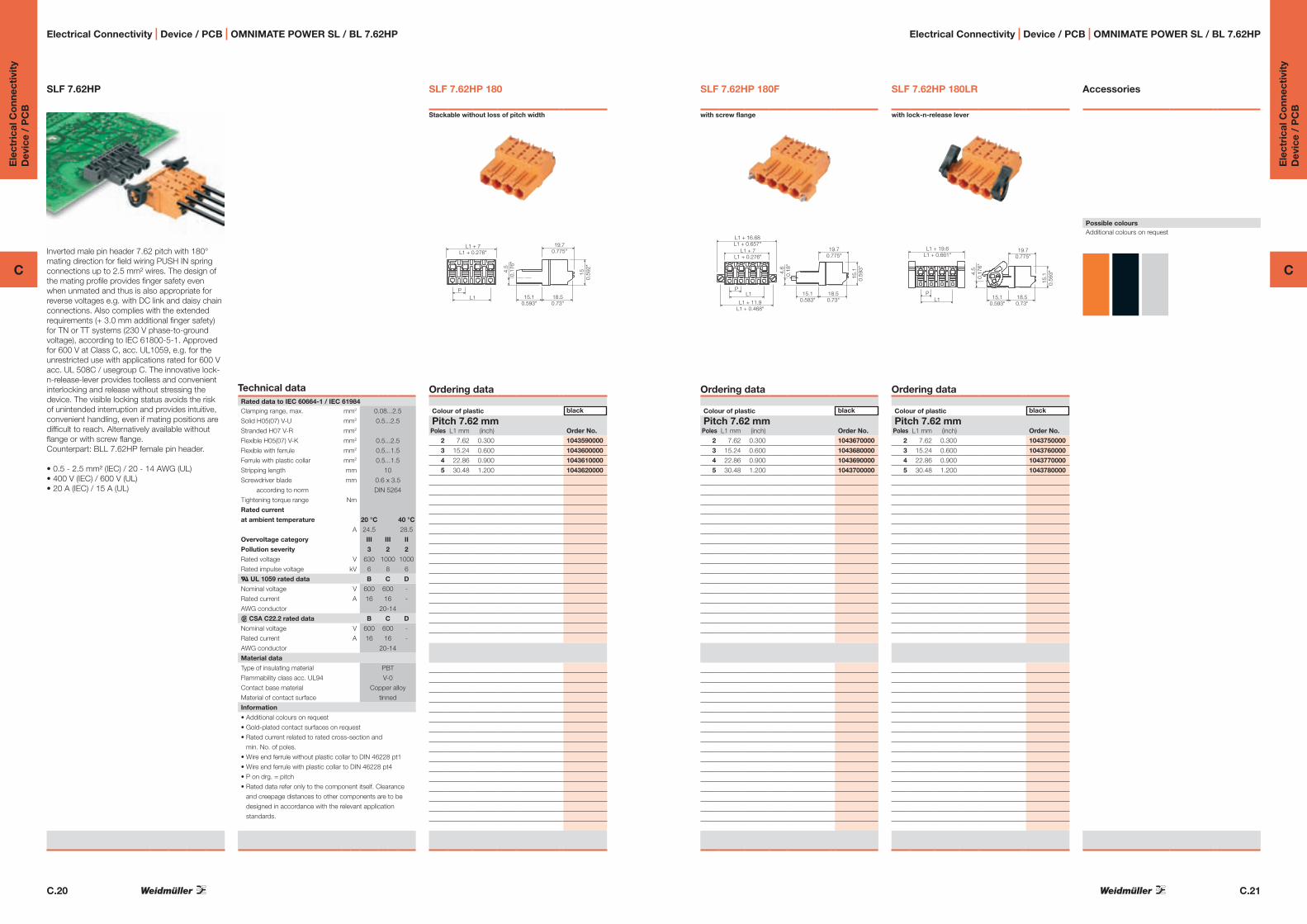
C.20
Ele
ctri
cal C
onn
ecti
vity
Dev
ice
/ P
CB
C
C.21
Ele
ctri
cal C
onn
ecti
vity
Dev
ice
/ P
CB
C
Electrical Connectivity | Device / PCB | OMNIMATE POWER SL / BL 7.62HP Electrical Connectivity | Device / PCB | OMNIMATE POWER SL / BL 7.62HP
SLF 7.62HP 180
Stackable without loss of pitch width
19.70.775"
4.5
0.17
6"
18.50.73"
15.10.593"
150.
592"
P
L1 + 7L1 + 0.276"
L1
Ordering data
Colour of plastic black
Pitch 7.62 mmPoles L1 mm (inch) Order No.
2 7.62 0.300 1043590000
3 15.24 0.600 1043600000
4 22.86 0.900 1043610000
5 30.48 1.200 1043620000
SLF 7.62HP
Inverted male pin header 7.62 pitch with 180° mating direction for field wiring PUSH IN spring connections up to 2.5 mm² wires. The design of the mating profile provides finger safety even when unmated and thus is also appropriate for reverse voltages e.g. with DC link and daisy chain connections. Also complies with the extended requirements (+ 3.0 mm additional finger safety) for TN or TT systems (230 V phase-to-ground voltage), according to IEC 61800-5-1. Approved for 600 V at Class C, acc. UL1059, e.g. for the unrestricted use with applications rated for 600 V acc. UL 508C / usegroup C. The innovative lock-n-release-lever provides toolless and convenient interlocking and release without stressing the device. The visible locking status avoids the risk of unintended interruption and provides intuitive, convenient handling, even if mating positions are difficult to reach. Alternatively available without flange or with screw flange. Counterpart: BLL 7.62HP female pin header.
• 0.5 - 2.5 mm² (IEC) / 20 - 14 AWG (UL)• 400 V (IEC) / 600 V (UL)• 20 A (IEC) / 15 A (UL)
SLF 7.62HP 180F
with screw flange
19.70.775"
4.6
0.18
"
15.10.583"
18.50.73"
15.1
0.59
3"
L1
L1 + 16.68L1 + 0.657"
L1 + 7L1 + 0.276"
P
L1 + 11.9L1 + 0.468"
Ordering data
Colour of plastic black
Pitch 7.62 mmPoles L1 mm (inch) Order No.
2 7.62 0.300 1043670000
3 15.24 0.600 1043680000
4 22.86 0.900 1043690000
5 30.48 1.200 1043700000
Accessories
Possible coloursAdditional colours on request
SLF 7.62HP 180LR
with lock-n-release lever
19.70.775"
4.5
0.17
6"
18.50.73"
15.10.593"
15.1
0.59
3"
P
L1 + 19.6L1 + 0.661"
L1
Ordering data
Colour of plastic black
Pitch 7.62 mmPoles L1 mm (inch) Order No.
2 7.62 0.300 1043750000
3 15.24 0.600 1043760000
4 22.86 0.900 1043770000
5 30.48 1.200 1043780000
Technical dataRated data to IEC 60664-1 / IEC 61984 Clamping range, max. mm2 0.08...2.5
Solid H05(07) V-U mm2 0.5...2.5
Stranded H07 V-R mm2
Flexible H05(07) V-K mm2 0.5...2.5
Flexible with ferrule mm2 0.5...1.5
Ferrule with plastic collar mm2 0.5...1.5
Stripping length mm 10
Screwdriver blade mm 0.6 x 3.5
according to norm DIN 5264
Tightening torque range Nm
Rated current
at ambient temperature 20 °C 40 °C
A 24.5 28.5
Overvoltage category III III II
Pollution severity 3 2 2
Rated voltage V 630 1000 1000
Rated impulse voltage kV 6 8 6
a UL 1059 rated data B C D
Nominal voltage V 600 600 -
Rated current A 16 16 -
AWG conductor 20-14
r CSA C22.2 rated data B C D
Nominal voltage V 600 600 -
Rated current A 16 16 -
AWG conductor 20-14
Material data
Type of insulating material PBT
Flammability class acc. UL94 V-0
Contact base material Copper alloy
Material of contact surface tinned
Information
• Additional colours on request
• Gold-plated contact surfaces on request
• Rated current related to rated cross-section and
min. No. of poles.
• Wire end ferrule without plastic collar to DIN 46228 pt1
• Wire end ferrule with plastic collar to DIN 46228 pt4
• P on drg. = pitch
• Rated data refer only to the component itself. Clearance
and creepage distances to other components are to be
designed in accordance with the relevant application
standards.

C.22
Ele
ctri
cal C
onn
ecti
vity
Dev
ice
/ P
CB
C
C.23
Ele
ctri
cal C
onn
ecti
vity
Dev
ice
/ P
CB
C
Electrical Connectivity | Device / PCB | OMNIMATE POWER SL / BL 7.62HP Electrical Connectivity | Device / PCB | OMNIMATE POWER SL / BL 7.62HP
BLF 7.62HP 180
Stackable without loss of pitch width
15.1
0.59
3"
19.20.757"
18.10.712"
8.90.348"
L1
L1 + 6.9L1 + 0.273"
4.2
0.16
7"
Ordering data
Colour of plastic black
Pitch 7.62 mmPoles L1 mm (inch) Order No.
2 7.62 0.300 1043830000
3 15.24 0.600 1043840000
4 22.86 0.900 1043850000
5 30.48 1.200 1043860000
BLF 7.62HP
Female socket block 7.62 pitch with 180° mating direction for field wiring PUSH IN spring connections up to 2.5 mm² wires. The design of the mating profile provides finger safety even when unmated and thus is also appropriate for reverse voltages e.g. at DC link and daisy chain connections. Also complies with the extended requirements (+ 3.0 mm additional finger safety) for TN or TT systems (230 V phase-to-ground voltage), according to IEC 61800-5-1. Approved for 600 V at Class C, acc. UL1059, e.g. for the unrestricted use with applications rated for 600 V acc. UL 508C / usegroup C. The innovative lock-n-release-lever provides toolless and convenient interlocking and release without stressing the device. The visible locking status avoids the risk of unintended interruption and provides intuitive, convenient handling, even if mating positions are difficult to reach. Alternatively available without flange or with screw flange. Counterpart: BLL 7.62HP female pin header.
• 0.5 - 2.5 mm² (IEC) / 20 - 14 AWG (UL)• 400 V (IEC) / 600 V (UL)• 20 A (IEC) / 16 A (UL)
BLF 7.62HP 180F
with screw flange
19.20.757"
4.2
0.16
7"
18.10.712"
8.90.348"
15.1
0.59
3"
L1P
L1 + 16.7L1 + 0.657"
L1 + 6.9L1 + 0.273"
L1 + 11.9L1 + 0.468"
Ordering data
Colour of plastic black
Pitch 7.62 mmPoles L1 mm (inch) Order No.
2 7.62 0.300 1043910000
3 15.24 0.600 1043920000
4 22.86 0.900 1043930000
5 30.48 1.200 1043940000
Accessories
Possible coloursAdditional colours on request
BLF 7.62HP 180LR
with lock-n-release lever
19.20.757"
4.3
0.16
7"
18.10.712"
8.90.348"
18.9
0.74
4"
L1
L1 + 18.6L1 + 0.661"
P
Ordering data
Colour of plastic black
Pitch 7.62 mmPoles L1 mm (inch) Order No.
2 7.62 0.300 1043990000
3 15.24 0.600 1044000000
4 22.86 0.900 1044010000
5 30.48 1.200 1044020000
Technical dataRated data to IEC 60664-1 / IEC 61984 Clamping range, max. mm2 0.08...2.5
Solid H05(07) V-U mm2 0.5...2.5
Stranded H07 V-R mm2
Flexible H05(07) V-K mm2 0.5...2.5
Flexible with ferrule mm2 0.5...1.5
Ferrule with plastic collar mm2 0.5...1.5
Stripping length mm 10
Screwdriver blade mm 0.6 x 3.5
according to norm DIN 5264
Tightening torque range Nm
Rated current
at ambient temperature 20 °C 40 °C
A 26 30
Overvoltage category III III II
Pollution severity 3 2 2
Rated voltage V 630 1000 1000
Rated impulse voltage kV 6 8 6
a UL 1059 rated data B C D
Nominal voltage V 600 600 -
Rated current A 16 16 -
AWG conductor 20-14
r CSA C22.2 rated data B C D
Nominal voltage V 600 600 -
Rated current A 16 16 -
AWG conductor 20-14
Material data
Type of insulating material PBT
Flammability class acc. UL94 V-0
Contact base material Copper alloy
Material of contact surface tinned
Information
• Additional colours on request
• Gold-plated contact surfaces on request
• Rated current related to rated cross-section and
min. No. of poles.
• Wire end ferrule without plastic collar to DIN 46228 pt1
• Wire end ferrule with plastic collar to DIN 46228 pt4
• P on drg. = pitch
• Rated data refer only to the component itself. Clearance
and creepage distances to other components are to be
designed in accordance with the relevant application
standards.

C.24
Ele
ctri
cal C
onn
ecti
vity
Dev
ice
/ P
CB
C
C.25
Ele
ctri
cal C
onn
ecti
vity
Dev
ice
/ P
CB
C
Electrical Connectivity | Device / PCB | OMNIMATE POWER SL / BL 7.62HP Electrical Connectivity | Device / PCB | OMNIMATE POWER SL / BL 7.62HP
BLL 7.62HP 90 G
Stackable without loss of pitch width
3.30.13"
10.6
0.41
8"
4.1
0.16
2"
13.20.52"
11.30.446"
10.4
0.40
9"
L1 Ø 1.3Ø 0.051"P
L1 + 6.8L1 + 0.27"
P
Ordering dataSolder pin length 3.2 mmColour of plastic black
Pitch 7.62 mmPoles L1 mm (inch) Order No.
2 7.62 0.300 1023530000
3 15.24 0.600 1023540000
4 22.86 0.900 1023550000
5 30.48 1.200 1023560000
BLL 7.62HP 90
Inverted female socket block 7.62 pitch with 90° mating direction for solder connection. Features a unique solder flange, which substitutes separate screw fastening due to automatic fixation during the soldering process. UL-approval for 600 V ratings appropriate in compliance with UL840. Complies with the extended requirements (+ 3.0 mm additional finger safety) for TN or TT systems (230 V phase-to-ground voltage), according to IEC 61800-5-1, even when unmated. As the design of the mating profile ensures a minimum distance of +3 mm between test finger and female contact at a pressure of 20 N, the BLL 7.62HP provides the perfect solution for finger safe power output or DC-link connections. Available without flange, with screw flange and optionally with solder flange. Counterpart: SLZ 7.62HP or SLF 7.62HP with PUSH IN spring connection.
• 400 V (IEC) / 300 V (UL)• 20 A (IEC) / 15 A (UL)• 600 V (UL) device approval is appropriate in
compliance with UL 840
BLL 7.62HP 90F
with screw flange
3.30.13"
10.6
0.41
8"
4.1
0.16
2"
13.20.52"
11.30.446"
10.4
0.40
9"
L1Ø 1.3Ø 0.051"
Ø 2.8Ø 0.11"
P
P
60.
236"
L1 + 16.8L1 + 0.662"
L1 + 11.88L1 + 0.468"
Ordering dataSolder pin length 3.2 mmColour of plastic black
Pitch 7.62 mmPoles L1 mm (inch) Order No.
2 7.62 0.300 1043270000
3 15.24 0.600 1043280000
4 22.86 0.900 1043290000
5 30.48 1.200 1043300000
Accessories
Possible coloursAdditional colours on request
BLL 7.62HP 90LF
with solder flange
11.30.446"
3.30.13"
10.6
0.41
8"
13.20.52"
10.4
0.40
9"
L1Ø 1.3Ø 0.051"
Ø 1.3Ø 0.051"
P
P
5.9
0.23
2"
L1 + 16.6L1 + 0.654"
L1 + 11.9L1 + 0.469"
4.1
0.16
2"
Ordering dataSolder pin length 3.2 mmColour of plastic black
Pitch 7.62 mmPoles L1 mm (inch) Order No.
2 7.62 0.300 1095640000
3 15.24 0.600 1095650000
4 22.86 0.900 1095660000
5 30.48 1.200 1095670000
Technical dataRated data to IEC 60664-1 / IEC 61984 Clamping range, max. mm2
Solid H05(07) V-U mm2
Stranded H07 V-R mm2
Flexible H05(07) V-K mm2
Flexible with ferrule mm2
Ferrule with plastic collar mm2
Stripping length mm
Screwdriver blade mm
according to norm
Tightening torque range Nm
Rated current
at ambient temperature 20 °C 40 °C
A 24 24
Overvoltage category III III II
Pollution severity 3 2 2
Rated voltage V 400 400 400
Rated impulse voltage kV 4 4 4
a UL 1059 rated data B C D
Nominal voltage V 300 300 600
Rated current A 15 15 5
AWG conductor
r CSA C22.2 rated data B C D
Nominal voltage V 300 300 600
Rated current A 15 15 5
AWG conductor
Material data
Type of insulating material PBT
Flammability class acc. UL94 V-0
Contact base material Copper alloy
Material of contact surface tinned
Information
• Additional colours on request
• Gold-plated contact surfaces on request
• Rated current related to rated cross-section and
min. No. of poles.
• P on drg. = pitch
• Rated data refer only to the component itself. Clearance
and creepage distances to other components are to be
designed in accordance with the relevant application
standards.

C.26
Ele
ctri
cal C
onn
ecti
vity
Dev
ice
/ P
CB
C
C.27
Ele
ctri
cal C
onn
ecti
vity
Dev
ice
/ P
CB
C
Electrical Connectivity | Device / PCB | OMNIMATE POWER SL / BL 7.62HP Electrical Connectivity | Device / PCB | OMNIMATE POWER SL / BL 7.62HP
BLL 7.62HP180 G
Stackable without loss of pitch width
4.10.162"
10.60.418"
11.3
0.44
6"
1.30.053"10.4
0.409"
13.2
0.52
"
L1 + 6.8L1 + 0.27"
Ø 1.3Ø 0.051"
P
L1
P
Ordering dataSolder pin length 3.2 mmColour of plastic black
Pitch 7.62 mmPoles L1 mm (inch) Order No.
2 7.62 0.300 on request
3 15.24 0.600 on request
4 22.86 0.900 on request
5 30.48 1.200 on request
BLL 7.62HP 180
Inverted female socket block 7.62 pitch with 180° mating direction for solder connection. Features a unique solder flange, which substitutes separate screw fastening due to automatic fixation during the soldering process. UL-approval for 600 V ratings appropriate in compliance with UL840. Complies with the extended requirements (+ 3.0 mm additional finger safety) for TN or TT systems (230 V phase-to-ground voltage), according to IEC 61800-5-1, even when unmated. As the design of themating profile ensures a minimum distance of +3 mm between test finger and female contact at a pressure of 20 N, the BLL 7.62HP provides the perfect solution for finger safe power output or DC-link connections. Available without flange, with screw flange and optionally with solder flange. Counterpart: SLZ 7.62HP or SLF 7.62HP with PUSH IN spring connection.
• 400 V (IEC) / 300 V (UL)• 20 A (IEC) / 15 A (UL)• 600 V (UL) device approval is appropriate in
compliance with UL 840
BLL 7.62HP 180F
with screw flange
4.10.162"
10.60.418"
11.3
0.44
6"
1.30.053"10.4
0.409"
13.2
0.52
"
L1 + 16.8L1 + 0.661"
L1 + 11.9L1 + 0.469"
Ø 1.3Ø 0.051"
P
L1
Ø 2.8Ø 0.11"
4.1
0.16
2"P
Ordering dataSolder pin length 3.2 mmColour of plastic black
Pitch 7.62 mmPoles L1 mm (inch) Order No.
2 7.62 0.300 on request
3 15.24 0.600 on request
4 22.86 0.900 on request
5 30.48 1.200 on request
Accessories
Possible coloursAdditional colours on request
BLL 7.62HP 180LF
with solder flange
4.10.162"
10.60.418"
1.30.053"10.4
0.409"
11.3
0.44
6"13
.20.
52"
L1 + 16.6L1 + 0.654"
L1 + 11.9L1 + 0.469"
Ø 1.3Ø 0.051"P
4.1
0.16
2"P
Ordering dataSolder pin length 3.2 mmColour of plastic black
Pitch 7.62 mmPoles L1 mm (inch) Order No.
2 7.62 0.300 on request
3 15.24 0.600 on request
4 22.86 0.900 on request
5 30.48 1.200 on request
Technical dataRated data to IEC 60664-1 / IEC 61984 Clamping range, max. mm2
Solid H05(07) V-U mm2
Stranded H07 V-R mm2
Flexible H05(07) V-K mm2
Flexible with ferrule mm2
Ferrule with plastic collar mm2
Stripping length mm
Screwdriver blade mm
according to norm
Tightening torque range Nm
Rated current
at ambient temperature 20 °C 40 °C
A on request*
Overvoltage category III III II
Pollution severity 3 2 2
Rated voltage V on request*
Rated impulse voltage kV on request*
a UL 1059 rated data B C D
Nominal voltage V on request*
Rated current A on request*
AWG conductor on request*
r CSA C22.2 rated data B C D
Nominal voltage V on request*
Rated current A on request*
AWG conductor on request*
Material data
Type of insulating material PBT
Flammability class acc. UL94 V-0
Contact base material Copper alloy
Material of contact surface tinned
Information
* Refer to http://catalog.weidmueller.com for product article
numbers and current specifications.
• Additional colours on request
• Gold-plated contact surfaces on request
• Rated current related to rated cross-section and
min. No. of poles.
• P on drg. = pitch
• Rated data refer only to the component itself. Clearance
and creepage distances to other components are to be
designed in accordance with the relevant application
standards.

C.28
Ele
ctri
cal C
onn
ecti
vity
Dev
ice
/ P
CB
C
C.29
Ele
ctri
cal C
onn
ecti
vity
Dev
ice
/ P
CB
C
Electrical Connectivity | Device / PCB | OMNIMATE POWER SV / BV 7.62HP Electrical Connectivity | Device / PCB | OMNIMATE POWER SV / BV 7.62HP
SV 7.62HP 90MF2 With one-hand-security flange at second position
(from left) optionally with solder flange
Ordering dataSolder pin length 3.5 mmColour of plastic black
Pitch 7.62 mmPoles L1 mm (inch) Order No.
2 7.62 0.300 1048390000
3 15.24 0.600 1048490000
4 22.86 0.900 on request
SV 7.62HP 90MF
Male pin header 7.62 pitch with 90° mating direction for solder connection. UL-approval for 600 V ratings appropriate in compliance with UL840. Complies with the extended requirements (+ 3.0 mm additional finger safety) for TN or TT systems (230 V phase-to-ground voltage), according to IEC 61800-5-1, even when unmated, as the design of the mating profile ensures a minimum distance of +3 mm between test finger and male contact at a pressure of 20 N. The innovative one-hand safety flange with automatic interlock function avoids the risk of unintended interruption and provides intuitive, convenient handling, even if mating positions are difficult to reach. Compared to state-of-the-art flange solutions, it also reduces the space by one pitch width. On request, the flange is alternatively available with additional fastening screw, or optionally without flange (closed version).Counterpart: BVZ 7.62HP or BVF 7.62HP with one-hand-safety flange (flange position to be considered)
• 1000 V (IEC) / 300 V (UL)• 41 A (IEC) / 35 A (UL)• 600 V (UL) device approval is appropriate in
compliance with UL 840
SV 7.62HP 90MF3
With one-hand-security flange at third position
(from left) optionally with solder flange
11.4
0.44
9"
L1 + P1 + O
13.30.524"
19.60.772"
28.31.114"
Ø 1.3Ø 0.051"
L1
P1
P1
11.4
0.44
8"
Ø 3.5Ø 0.143"
Ordering dataSolder pin length 3.5 mmColour of plastic black
Pitch 7.62 mmPoles L1 mm (inch) Order No.
3 15.24 0.600 1048500000
4 22.86 0.900 1048570000
5 30.48 1.200 1048680000
6 38.10 1.500 on request
Accessories
Possible coloursAdditional colours on request
Additional flange configurationson request
SV 7.62HP 90MF4
With one-hand-security flange at fourth position
(from left) optionally with solder flange
Ordering dataSolder pin length 3.5 mmColour of plastic black
Pitch 7.62 mmPoles L1 mm (inch) Order No.
4 22.86 0.900 on request
5 30.48 1.200 1048690000
6 38.10 1.500 1048760000
Technical dataRated data to IEC 60664-1 / IEC 61984 Clamping range, max. mm2
Solid H05(07) V-U mm2
Stranded H07 V-R mm2
Flexible H05(07) V-K mm2
Flexible with ferrule mm2
Ferrule with plastic collar mm2
Stripping length mm
Screwdriver blade mm
according to norm
Tightening torque range Nm
Rated current
at ambient temperature 20 °C 40 °C
A 41 41
Overvoltage category III III II
Pollution severity 3 2 2
Rated voltage V 630 630 1000
Rated impulse voltage kV 6 6 6
a UL 1059 rated data B C D
Nominal voltage V 300 300 600
Rated current A 35 35 5
AWG conductor
r CSA C22.2 rated data B C D
Nominal voltage V 300 300 600
Rated current A 35 35 5
AWG conductor
Material data
Type of insulating material PA GF
Flammability class acc. UL94 V-0
Contact base material Copper alloy
Material of contact surface tinned
Information
• Additional colours on request
• Gold-plated contact surfaces on request
• Rated current related to rated cross-section and
min. No. of poles.
• P on drg. = pitch
• Rated data refer only to the component itself. Clearance
and creepage distances to other components are to be
designed in accordance with the relevant application
standards.
1
1
1
MF2
MF2
MF2
2
2
2
3
3 4
Drawings for the MF2 variants are available on request
1 2 3 MF4 4
Drawings for the MF4 variants are available on request

C.30
Ele
ctri
cal C
onn
ecti
vity
Dev
ice
/ P
CB
C
C.31
Ele
ctri
cal C
onn
ecti
vity
Dev
ice
/ P
CB
C
Electrical Connectivity | Device / PCB | OMNIMATE POWER SV / BV 7.62HP Electrical Connectivity | Device / PCB | OMNIMATE POWER SV / BV 7.62HP
SV 7.62HP 180MF2 With one-hand-security flange at second position
(from left) optionally with solder flange
Ordering dataSolder pin length 3.5 mmColour of plastic black
Pitch 7.62 mmPoles L1 mm (inch) Order No.
2 7.62 0.300 1048350000
3 15.24 0.600 1048410000
4 22.86 0.900 on request
SV 7.62HP 180MF
Male pin header 7.62 pitch with 180° mating direction for solder connection. UL-approval for 600 V ratings appropriate in compliance with UL840. Complies with the extended requirements (+ 3.0 mm additional finger safety) for TN or TT systems (230 V phase-to-ground voltage), according to IEC 61800-5-1, even when unmated, as the design of the mating profile ensures a minimum distance of +3 mm between test finger and male contact at a pressure of 20 N. The innovative one-hand safety flange with automatic interlock function avoids the risk of unintended interruption and provides intuitive, convenient handling, even if mating positions are difficult to reach. Compared to state-of-the-art flange solutions, it also reduces the space by one pitch width. On request, the flange is alternatively available with additional fastening screw, or optionally without flange (closed version).Counterpart: BVZ 7.62HP or BVF 7.62HP with one-hand-safety flange (flange position to be considered)
• 1000 V (IEC) / 300 V (UL)• 41 A (IEC) / 35 A (UL)• 600 V (UL) device approval is appropriate in
compliance with UL 840
SV 7.62HP 180MF3
With one-hand-security flange at third position
(from left) optionally with solder flange
L1 + P 11.40.449"
1.90.074"
Ø 1.3 + 0.1Ø 0.051"
P1
L1
P1
P/2 Ø 2.1 + 0.1Ø 0.083"
Ø 3.7 + 0.1Ø 0.146"
3.8
0.15
"
5.4
0.21
2"
28.3
1.11
4"
Ordering dataSolder pin length 3.5 mmColour of plastic black
Pitch 7.62 mmPoles L1 mm (inch) Order No.
3 15.24 0.600 1048420000
4 22.86 0.900 1048580000
5 30.48 1.200 1048590000
6 38.10 1.500 on request
Accessories
Possible coloursAdditional colours on request
Additional flange configurationson request
SV 7.62HP 180MF4
With one-hand-security flange at fourth position
(from left) optionally with solder flange
Ordering dataSolder pin length 3.5 mmColour of plastic black
Pitch 7.62 mmPoles L1 mm (inch) Order No.
4 22.86 0.900 on request
5 30.48 1.200 1048600000
6 38.10 1.500 1048720000
Technical dataRated data to IEC 60664-1 / IEC 61984 Clamping range, max. mm2
Solid H05(07) V-U mm2
Stranded H07 V-R mm2
Flexible H05(07) V-K mm2
Flexible with ferrule mm2
Ferrule with plastic collar mm2
Stripping length mm
Screwdriver blade mm
according to norm
Tightening torque range Nm
Rated current
at ambient temperature 20 °C 40 °C
A 41 41
Overvoltage category III III II
Pollution severity 3 2 2
Rated voltage V 630 630 1000
Rated impulse voltage kV 6 6 6
a UL 1059 rated data B C D
Nominal voltage V 300 300 600
Rated current A 35 35 5
AWG conductor
r CSA C22.2 rated data B C D
Nominal voltage V 300 300 600
Rated current A 35 35 5
AWG conductor
Material data
Type of insulating material PA GF
Flammability class acc. UL94 V-0
Contact base material Copper alloy
Material of contact surface tinned
Information
• Additional colours on request
• Gold-plated contact surfaces on request
• Rated current related to rated cross-section and
min. No. of poles.
• P on drg. = pitch
• Rated data refer only to the component itself. Clearance
and creepage distances to other components are to be
designed in accordance with the relevant application
standards.
1
1
1
MF2
MF2
MF2
2
2
2
3
3 4
Drawings for the MF2 variants are available on request
1 2 3 MF4 4
Drawings for the MF4 variants are available on request

C.32
Ele
ctri
cal C
onn
ecti
vity
Dev
ice
/ P
CB
C
C.33
Ele
ctri
cal C
onn
ecti
vity
Dev
ice
/ P
CB
C
Electrical Connectivity | Device / PCB | OMNIMATE POWER SV / BV 7.62HP Electrical Connectivity | Device / PCB | OMNIMATE POWER SV / BV 7.62HP
SV 7.62HP 270MF2 With one-hand-security flange at second position
(from left) optionally with solder flange
Ordering dataSolder pin length 3.5 mmColour of plastic black
Pitch 7.62 mmPoles L1 mm (inch) Order No.
2 7.62 0.300 1048370000
3 15.24 0.600 1048450000
4 22.86 0.900 on request
SV 7.62HP 270MF
Male pin header 7.62 pitch with 270° mating direction for solder connection. UL-approval for 600 V ratings appropriate in compliance with UL840. Complies with the extended requirements (+ 3.0 mm additional finger safety) for TN or TT systems (230 V phase-to-ground voltage), according to IEC 61800-5-1, even when unmated, as the design of the mating profile ensures a minimum distance of +3 mm between test finger and male contact at a pressure of 20 N. The innovative one-hand safety flange with automatic interlock function avoids the risk of unintended interruption and provides intuitive, convenient handling, even if mating positions are difficult to reach. Compared to state-of-the-art flange solutions, it also reduces the space by one pitch width. On request, the flange is alternatively available with additional fastening screw, or optionally without flange (closed version). Counterpart: BVZ 7.62HP or BVF 7.62HP with one-hand-safety flange (flange position to be considered)
• 1000 V (IEC) / 300 V (UL)• 41 A (IEC) / 35 A (UL)• 600 V (UL) device approval is appropriate in
compliance with UL 840
SV 7.62HP 270MF3
With one-hand-security flange at third position
(from left) optionally with solder flange
19.80.78"8
0.315"
13.30.524"28.3
1.114"
L1 + P1
11.4
0.44
9"
P1L1
P1
Ø 3.5Ø 0.143"
Ø 1.3Ø 0.051"
11.4
0.44
8"
Ordering dataSolder pin length 3.5 mmColour of plastic black
Pitch 7.62 mmPoles L1 mm (inch) Order No.
3 15.24 0.600 1048460000
4 22.86 0.900 1048540000
5 30.48 1.200 1048640000
6 38.10 1.500 on request
Accessories
Possible coloursAdditional colours on request
Additional flange configurationson request
SV 7.62HP 270MF4
With one-hand-security flange at fourth position
(from left) optionally with solder flange
Ordering dataSolder pin length 3.5 mmColour of plastic black
Pitch 7.62 mmPoles L1 mm (inch) Order No.
4 22.86 0.900 on request
5 30.48 1.200 1048650000
6 38.10 1.500 1048740000
Technical dataRated data to IEC 60664-1 / IEC 61984 Clamping range, max. mm2
Solid H05(07) V-U mm2
Stranded H07 V-R mm2
Flexible H05(07) V-K mm2
Flexible with ferrule mm2
Ferrule with plastic collar mm2
Stripping length mm
Screwdriver blade mm
according to norm
Tightening torque range Nm
Rated current
at ambient temperature 20 °C 40 °C
A 41 41
Overvoltage category III III II
Pollution severity 3 2 2
Rated voltage V 630 630 1000
Rated impulse voltage kV 6 6 6
a UL 1059 rated data B C D
Nominal voltage V 300 300 600
Rated current A 35 5
AWG conductor
r CSA C22.2 rated data B C D
Nominal voltage V 300 300 600
Rated current A 35 35 5
AWG conductor
Material data
Type of insulating material PA GF
Flammability class acc. UL94 V-0
Contact base material Copper alloy
Material of contact surface tinned
Information
• Additional colours on request
• Gold-plated contact surfaces on request
• Rated current related to rated cross-section and
min. No. of poles.
• P on drg. = pitch
• Rated data refer only to the component itself. Clearance
and creepage distances to other components are to be
designed in accordance with the relevant application
standards.
1
1
1
MF2
MF2
MF2
2
2
2
3
3 4
Drawings for the MF2 variants are available on request
1 2 3 MF4 4
Drawings for the MF4 variants are available on request

C.34
Ele
ctri
cal C
onn
ecti
vity
Dev
ice
/ P
CB
C
C.35
Ele
ctri
cal C
onn
ecti
vity
Dev
ice
/ P
CB
C
Electrical Connectivity | Device / PCB | OMNIMATE POWER SV / BV 7.62HP Electrical Connectivity | Device / PCB | OMNIMATE POWER SV / BV 7.62HP
SVF 7.62HP 180 Stackable without loss of pitch width
29.211.15"L1
P
L1 + 8.52L1 + 0.335"
15.80.62"
6.8
0.27
"
200.
79"
Ordering data
Colour of plastic black
Pitch 7.62 mmPoles L1 mm (inch) Order No.
2 7.62 0.300 1060830000
3 15.24 0.600 1060840000
4 22.86 0.900 1060850000
5 30.48 1.200 1060870000
6 38.10 1.500 1060880000
SVF 7.62HP 180
Inverted male pin header 7.62 pitch with 180° mating direction for field wiring PUSH IN spring connections up to 6.0 mm² wires. The design of the mating profile provides finger safety even when unmated and thus is also appropriate for reverse voltages e.g. with DC link and daisy chain connections. Also complies with the extended requirements (+ 3.0 mm additional finger safety) for TN or TT systems (230 V phase-to-ground voltage), according to IEC 61800-5-1. Approved for 600 V at Class C, acc. UL1059, e.g. for the unrestricted use with applications rated for 600 V acc. UL 508C / usegroup C. Available without flange, with toolless lockable snap-on flange or with additional fastening screw. Counterpart: BVL 7.62HP (only without flanges) for board-to-wire connections, or BVZ 7.62HP or BVF 7.62HP female socket block for wire-to-wire connections.
Preliminary technical specifications:• 0.2 - 10 mm² (IEC) / 28 - 12 AWG (UL)• 1000 V (IEC) / 600 V (UL)• 41 A (IEC) / 35 A (UL)
SVF 7.62HP 180F
With clip-on flange
L1 + 22.86L1 + 0.9"
29.21.150"L1
P
L1 + 8.52L1 + 0.335"
15.80.622"6.
80.
268"
20.0
0.78
7"
Ordering data
Colour of plastic black
Pitch 7.62 mmPoles L1 mm (inch) Order No.
2 7.62 0.300 1060900000
3 15.24 0.600 1060910000
4 22.86 0.900 1060920000
5 30.48 1.200 1060930000
6 38.10 1.500 1060940000
Accessories
Possible coloursAdditional colours on request
SVF 7.62HP 180SF
With clip-on flange and additional flange screw fitting
L1 + 22.86L1 + 0.9"
29.21.150"L1
P
L1 + 8.52L1 + 0.335"
15.80.622"6.
80.
268"
20.0
0.78
7"
Ordering data
Colour of plastic black
Pitch 7.62 mmPoles L1 mm (inch) Order No.
2 7.62 0.300 1060950000
3 15.24 0.600 1060970000
4 22.86 0.900 1060980000
5 30.48 1.200 1061000000
6 38.10 1.500 1061010000
Technical dataRated data to IEC 60664-1 / IEC 61984 Clamping range, max. mm2 0.5...10
Solid H05(07) V-U mm2 0.5...10
Stranded H07 V-R mm2 1.5...10
Flexible H05(07) V-K mm2 0.5...10
Flexible with ferrule mm2 1.5...4
Ferrule with plastic collar mm2 1.5...6
Stripping length mm 12
Screwdriver blade mm
according to norm DIN 5261
Tightening torque range Nm
Rated current
at ambient temperature 20 °C 40 °C
A 41* 41*
Overvoltage category III III II
Pollution severity 3 2 2
Rated voltage V 800* 1000* 1000*
Rated impulse voltage kV 8* 8* 6*
a UL 1059 rated data B C D
Nominal voltage V 600 600 -
Rated current A 35* 35* -*
AWG conductor 20-10
r CSA C22.2 rated data B C D
Nominal voltage V 600 600 -
Rated current A 35* 35* -*
AWG conductor 20-10
Material data
Type of insulating material PA GF
Flammability class acc. UL94 V-0
Contact base material Copper alloy
Material of contact surface tinned
Information
(*) These values are preliminary. Refer to
http://catalog.weidmueller.com for current specifications.
• Gold-plated contact surfaces on request
• Rated current related to rated cross-section and
min. No. of poles.
• Wire end ferrule without plastic collar to DIN 46228 pt1
• Wire end ferrule with plastic collar to DIN 46228 pt4
• P on drg. = pitch
• Rated data refer only to the component itself. Clearance
and creepage distances to other components are to be
designed in accordance with the relevant application
standards.

C.36
Ele
ctri
cal C
onn
ecti
vity
Dev
ice
/ P
CB
C
C.37
Ele
ctri
cal C
onn
ecti
vity
Dev
ice
/ P
CB
C
Electrical Connectivity | Device / PCB | OMNIMATE POWER SV / BV 7.62HP Electrical Connectivity | Device / PCB | OMNIMATE POWER SV / BV 7.62HP
SVF 7.62HP 180FI With clip-on flange
L1 + 22.86L1 + 0.9"
29.21.15"L1
P
L1 + 15.2L1 + 0.598"L1 + 8.52
L1 + 0.335"
15.80.623"6.
80.
268"
200.
787"
Ordering data
Colour of plastic black
Pitch 7.62 mmPoles L1 mm (inch) Order No.
2 7.62 0.300 1124750000
3 15.24 0.600 1124760000
4 22.86 0.900 1124770000
5 30.48 1.200 1124780000
6 38.10 1.500 1124790000
SVF 7.62HP 180FI
Inverted male pin header 7.62 pitch with 180° mating direction for field wiring PUSH IN spring connections up to 6.0 mm² wires. This variant features inverted „active“ flanges so that the SVZ can be used as the plugged half of the connection. The design of the mating profile provides finger safety even when unmated and thus is also appropriate for reverse voltages e.g. with DC link and daisy chain connections. Also complies with the extended requirements (+ 3.0 mm additional finger safety) for TN or TT systems (230 V phase-to-ground voltage), according to IEC 61800-5-1. Approved for 600 V at Class C, acc. UL1059, e.g. for the unrestricted use with applications rated for 600 V acc. UL 508C / usegroup C. Available without flange, with toolless lockable snap-on flange or with additional fastening screw. Counterpart: BVL 7.62HP female pin header for board-to-wire-connections or BVZ 7.62HP or BVF 7.62HP female socket block with inverted flanges for wire-to-wire-connections.
Preliminary technical specifications:• 0.2 - 10 mm² (IEC) / 28 - 12 AWG (UL)• 1000 V (IEC) / 600 V (UL)• 41 A (IEC) / 35 A (UL)
SVF 7.62HP 180SFI
With clip-on flange and additional flange screw fitting
29.21.15"L1
P
L1 + 8.52L1 + 0.335"
15.80.622"6.
80.
268"
200.
787"
L1 + 15.2L1 + 0.598"
L1 + 22.86L1 + 0.9"
Ordering data
Colour of plastic black
Pitch 7.62 mmPoles L1 mm (inch) Order No.
2 7.62 0.300 1124810000
3 15.24 0.600 1124820000
4 22.86 0.900 1124830000
5 30.48 1.200 1124840000
6 38.10 1.500 1124850000
Accessories
Possible coloursAdditional colours on request
Technical dataRated data to IEC 60664-1 / IEC 61984 Clamping range, max. mm2 0.5...10
Solid H05(07) V-U mm2 0.5...10
Stranded H07 V-R mm2 1.5...10
Flexible H05(07) V-K mm2 0.5...10
Flexible with ferrule mm2 1.5...4
Ferrule with plastic collar mm2 1.5...6
Stripping length mm 12
Screwdriver blade mm
according to norm DIN 5262
Tightening torque range Nm
Rated current
at ambient temperature 20 °C 40 °C
A 41* 41*
Overvoltage category III III II
Pollution severity 3 2 2
Rated voltage V 800* 1000* 1000*
Rated impulse voltage kV 8* 8* 6*
a UL 1059 rated data B C D
Nominal voltage V 600* 600* -*
Rated current A 35* 35* -*
AWG conductor 20-10
r CSA C22.2 rated data B C D
Nominal voltage V 600* 600* -*
Rated current A 35* 35* -*
AWG conductor 20-10
Material data
Type of insulating material PA GF
Flammability class acc. UL94 V-0
Contact base material Copper alloy
Material of contact surface tinned
Information
(*) These values are preliminary. Refer to
http://catalog.weidmueller.com for current specifications.
*Product article numbers available on request.
• Additional colours on request
• Gold-plated contact surfaces on request
• Rated current related to rated cross-section and
min. No. of poles.
• Wire end ferrule without plastic collar to DIN 46228 pt1
• Wire end ferrule with plastic collar to DIN 46228 pt4
• P on drg. = pitch
• Rated data refer only to the component itself. Clearance
and creepage distances to other components are to be
designed in accordance with the relevant application standards.

C.38
Ele
ctri
cal C
onn
ecti
vity
Dev
ice
/ P
CB
C
C.39
Ele
ctri
cal C
onn
ecti
vity
Dev
ice
/ P
CB
C
Electrical Connectivity | Device / PCB | OMNIMATE POWER SV / BV 7.62HP Electrical Connectivity | Device / PCB | OMNIMATE POWER SV / BV 7.62HP
SVF 7.62HP 180MF With one-hand-security flange
15.80.62"
6.8
0.27
"
29.21.15"
200.
79"
22.9
0.9"
L1P
L1 + 8.5L1 + 0.335"
Ordering data
Colour of plastic black
Pitch 7.62 mmPoles L1 mm (inch) Order No.
2 7.62 0.300 MF2 1061020000
3 15.24 0.600 MF2 1061030000
3 15.24 0.600 MF3 1061040000
4 22.86 0.900 MF3 1061050000
5 30.48 1.200 MF3 1061070000
5 30.48 1.200 MF4 1061080000
6 38.10 1.500 MF4 1061100000
SVF 7.62HP 180MF
Inverted male pin header 7.62 pitch with 180° mating direction for field wiring PUSH IN spring connections up to 6.0 mm² wires. The design of the mating profile provides finger safety even when unmated and thus is also appropriate for reverse voltages e.g. with DC link and daisy chain connections. Also complies with the extended requirements (+ 3.0 mm additional finger safety) for TN or TT systems (230 V phase-to-ground voltage), according to IEC 61800-5-1. Approved for 600 V at Class C, acc. UL1059, e.g. for the unrestricted use with applications rated for 600 V acc. UL 508C / usegroup C. The innovative one-hand safety flange with automatic interlock function avoids the risk of unintended interruption and provides intuitive, convenient handling, even if mating positions are difficult to reach. Compared to state-of-the-art flange solutions, it also reduces the space by one pitch width. On request, the flange is alternatively available with additional fastening screw. Counterpart: BVL 7.62HP fpr board-to-wire-connection or BVF 7.62HP with one-hand-safety flange (flange position to be considered) for wire-to-wire connections
Preliminary technical specifications:• 0.2 - 10 mm² (IEC) / 28 - 12 AWG (UL)• 1000 V (IEC) / 600 V (UL)• 41 A (IEC) / 35 A (UL)
SVF 7.62HP 180MSF
With one-hand-security flange and additional
flange fitting
L1P
L1 + 8.5L1 + 0.335"
15.80.62"
6.8
0.27
"
29.21.15"
200.
79"
22.9
0.9"
Ordering data
Colour of plastic black
Pitch 7.62 mmPoles L1 mm (inch) Flange Order No.
2 7.62 0.300 MSF2 1061110000
3 15.24 0.600 MSF2 1061120000
3 15.24 0.600 MSF3 1061130000
4 22.86 0.900 MSF3 1061140000
5 30.48 1.200 MSF3 1061150000
5 30.48 1.200 MSF4 1061170000
6 38.10 1.500 MSF4 1061180000
Accessories
Possible coloursAdditional colours on request
Technical dataRated data to IEC 60664-1 / IEC 61984 Clamping range, max. mm2 0.5...10
Solid H05(07) V-U mm2 0.5...10
Stranded H07 V-R mm2 1.5...10
Flexible H05(07) V-K mm2 0.5...10
Flexible with ferrule mm2 1.5...4
Ferrule with plastic collar mm2 1.5...6
Stripping length mm 12
Screwdriver blade mm
according to norm DIN 5263
Tightening torque range Nm
Rated current
at ambient temperature 20 °C 40 °C
A 41* 41*
Overvoltage category III III II
Pollution severity 3 2 2
Rated voltage V 800* 1000* 1000*
Rated impulse voltage kV 8* 8* 6*
a UL 1059 rated data B C D
Nominal voltage V 600* 600* -*
Rated current A 35* 35* -*
AWG conductor 20-10
r CSA C22.2 rated data B C D
Nominal voltage V 600* 600* -*
Rated current A 35* 35* -*
AWG conductor 20-10
Material data
Type of insulating material PA GF
Flammability class acc. UL94 V-0
Contact base material Copper alloy
Material of contact surface tinned
Information
(*) These values are preliminary. Refer to
http://catalog.weidmueller.com for current specifications.
*Product article numbers available on request.
• Additional colours on request
• Gold-plated contact surfaces on request
• Rated current related to rated cross-section and
min. No. of poles.
• Wire end ferrule without plastic collar to DIN 46228 pt1
• Wire end ferrule with plastic collar to DIN 46228 pt4
• P on drg. = pitch
• Rated data refer only to the component itself. Clearance
and creepage distances to other components are to be
designed in accordance with the relevant application standards.
Flange position in illustration: MF3 Flange position in illustration: MSF3

C.40
Ele
ctri
cal C
onn
ecti
vity
Dev
ice
/ P
CB
C
C.41
Ele
ctri
cal C
onn
ecti
vity
Dev
ice
/ P
CB
C
Electrical Connectivity | Device / PCB | OMNIMATE POWER SV / BV 7.62HP Electrical Connectivity | Device / PCB | OMNIMATE POWER SV / BV 7.62HP
BVF 7.62 HP 180
Stackable without loss of pitch width
29.21.15"
200.
79"
15.50.61"
L1
L1 + 8.52L1 + 0.335"
P
Ordering data
Colour of plastic black
Pitch 7.62 mmPoles L1 mm (inch) Order No.
2 7.62 0.300 1060390000
3 15.24 0.600 1060400000
4 22.86 0.900 1060410000
5 30.48 1.200 1060420000
6 38.10 1.500 1060430000
BVF 7.62 HP
Female socket block 7.62 pitch with 180° mating direction for field wiring PUSH IN spring connections up to 6.0 mm² wires. Approved for 600 V at Class C, acc. UL1059, e.g. for the unrestricted use with applications rated for 600 V acc. UL 508C / usegroup C. Complies with the extended requirements (+ 3.0 mm additional finger safety) for TN or TT systems (230 V phase-to-ground voltage), according to IEC 61800-5-1. The innovative one-hand safety flange with automatic interlock function avoids the risk of unintended interruption and provides intuitive, convenient handling, even if mating positions are difficult to reach. Compared to state-of-the-art flange solutions, it also reduces the space by one pitch width. On request, the flange is alternatively available with additional screw, or optionally without flange. Counterpart: SV 7.62HP pin header for wire-to-board connections or BVF 7.62HP for wire-to-wire connections, both with one-hand safety flange.
• 0.2 - 10.0 mm² (IEC) / 24 - 12 AWG (UL)• 1000 V (IEC) / 600 V (UL)• 38 A (IEC) / 35 A (UL)
BVF 7.62 HP 180MF
With one-hand-security flange
29.21.15"
200.
79"
15.50.61"
22.9
0.9"
P
L1 + 8.52L1 + 0.335"
L1
Ordering dataSolder pin lengthColour of plastic black
Pitch 7.62 mmPoles L1 mm (inch) Flange Order No.
2 7.62 0.300 MF2 1060550000
3 15.24 0.600 MF2 1060570000
3 15.24 0.600 MF3 1060580000
4 22.86 0.900 MF3 1060590000
5 30.48 1.200 MF3 1060600000
5 30.48 1.200 MF4 1060610000
6 38.10 1.500 MF4 1060620000
Accessories
Possible coloursAdditional colours on request
BVF 7.62 HP 180MSF
With one-hand-security flange and additional
flange fitting
29.21.15"
200.
79"
15.50.61"
22.9
0.9"
L1
L1 + 8.52L1 + 0.335"
P
Ordering dataSolder pin lengthColour of plastic black
Pitch 7.62 mmPoles L1 mm (inch) Flange Order No.
2 7.62 0.300 MSF2 1060630000
3 15.24 0.600 MSF2 1060640000
3 15.24 0.600 MSF3 1060650000
4 22.86 0.900 MSF3 1060670000
5 30.48 1.200 MSF3 1060680000
5 30.48 1.200 MSF4 1060690000
6 38.10 1.500 MSF4 1060700000
Technical dataRated data to IEC 60664-1 / IEC 61984 Clamping range, max. mm2 0.5...10
Solid H05(07) V-U mm2 0.5...10
Stranded H07 V-R mm2 1.5...10
Flexible H05(07) V-K mm2 0.5...10
Flexible with ferrule mm2 1.5...4
Ferrule with plastic collar mm2 1.5...6
Stripping length mm 12
Screwdriver blade mm 0.8 x 4.5
according to norm DIN 5264
Tightening torque range Nm
Rated current
at ambient temperature 20 °C 40 °C
A 41 41
Overvoltage category III III II
Pollution severity 3 2 2
Rated voltage V 800 1000 1000
Rated impulse voltage kV 8 8 6
a UL 1059 rated data B C D
Nominal voltage V 600 600 -
Rated current A 35 35 -
AWG conductor 24-10
r CSA C22.2 rated data B C D
Nominal voltage V 600 600 -
Rated current A 35 35 -
AWG conductor 24-10
Material data
Type of insulating material PA GF
Flammability class acc. UL94 V-0
Contact base material Copper alloy
Material of contact surface tinned
Information
• Additional colours on request
• Gold-plated contact surfaces on request
• Rated current related to rated cross-section and
min. No. of poles.
• AEH ohne Kunststoffkragen nach DIN 46228/1
• Wire end ferrule with plastic collar to DIN 46228 pt4
• P on drg. = pitch
• Rated data refer only to the component itself. Clearance
and creepage distances to other components are to be
designed in accordance with the relevant application
standards.
Flange position in illustration: MF3 Flange position in illustration: MSF3

C.42
Ele
ctri
cal C
onn
ecti
vity
Dev
ice
/ P
CB
C
C.43
Ele
ctri
cal C
onn
ecti
vity
Dev
ice
/ P
CB
C
Electrical Connectivity | Device / PCB | OMNIMATE POWER SV / BV 7.62HP Hybrid Electrical Connectivity | Device / PCB | OMNIMATE POWER SV / BV 7.62HP Hybrid
SV 7.62HP SC 3.81 90
With integrated signal contacts
28.31.114"
11.4
0.44
9"
13.30.524"
80.315"
19.80.78"
O = L2 + 4.8O = L2 + 0.186"
L1 + P1 + O
L2
Ø 1.3Ø 0.051"
P1
P2
L1
P1
P2
Ø 1.2Ø 0.047"
Ordering dataSolder pin length 3.5 mmColour of plastic black
Pitch 7.62 / 3.81 mmPoles L1 mm (inch) Order No.
2/4 7.62 0.300 1089840000
2/6 7.62 0.300 1089920000
2/8 7.62 0.300 1157040000
3/4 15.24 0.600 1090040000
3/6 15.24 0.600 1090120000
3/8 15.24 0.600 1157050000
4/4 22.86 0.900 1090280000
4/6 22.86 0.900 1090360000
4/8 22.86 0.900 1157380000
5/4 30.48 1.200 1090520000
5/6 30.48 1.200 1090590000
5/8 30.48 1.200 1157080000
SV 7.62HP 90 SC 3.81
Hybrid male power/signal- pin header 7.62 pitch with 90° mating direction for solder connection. Featuring 3 main functions - integrated to one system: power, signal and EMC shield connection. Innovative details such as pluggable hybrid shield connection and one-hand safety autolock flange allow to connect power, signals and EMC shielding simultaneously with only one instead of 3 steps. UL-approval for 600 V ratings appropriate in compliance with UL840. Complies with the extended requirements (+ 3.0 mm additional finger safety) for TN or TT systems (230 V phase-to-ground voltage), according to IEC 61800-5-1, even when unmated, as the design of the mating profile ensures a minimum distance of +3 mm between test finger and male contact at a pressure of 20 N. (referring to power contacts).The innovative one-hand safety flange with automatic interlock function avoids the risk of unintended interruption and provides intuitive, convenient handling, even if mating positions are difficult to reach. Compared to state-of-the-art, the space required on the board or housing is significantly reduced. On request, the flange is alternatively available with additional fastening screw, or optionally without flange (closed version). Counterpart: BVF 7.62HP -BCF 3.81 with one-hand-safety flange (flange position to be considered)
Preliminary technical specifications• 1000 V (IEC) / 300 V (UL)• 38 A (IEC) / 35 A (UL)• 600 V (UL) device approval is appropriate in
compliance with UL 840
SV 7.62HP SC 3.81 90 MF
With integrated signal contacts and
one-hand-security flange
11.4
0.44
9"
O = L2 + 4.8O = L2 + 0.189"L1 + P1 + O
L2
28.31.114"
13.30.524"
80.315"
19.80.78"
Ø 1.3Ø 0.051"P1
P2
L1
P1
P2
Ø 1.2Ø 0.047"
P1
11.4
0.44
8"
Ø 3.5Ø 0.143"
Ordering dataSolder pin length 3.5 mmColour of plastic black
Pitch 7.62 / 3.81 mmPoles L1 mm (inch) Flange Order No.
2/4 7.62 0.300 MF2 1089370000
2/6 7.62 0.300 MF2 1089410000
2/8 7.62 0.300 MF2 1156820000
3/4 15.24 0.600 MF2 1156230000
3/6 15.24 0.600 MF2 1156240000
3/8 15.24 0.600 MF2 1156840000
3/4 15.24 0.600 MF3 1089660000
3/6 15.24 0.600 MF3 1089730000
3/8 15.24 0.600 MF3 1156850000
4/4 22.86 0.900 MF4 1090130000
4/6 22.86 0.900 MF4 1090210000
4/8 22.86 0.900 MF4 1156890000
5/4 30.48 1.200 MF3 1156910000
5/6 30.48 1.200 MF3 1156930000
5/8 30.48 1.200 MF3 1156950000
5/4 30.48 1.200 MF4 1090600000
5/6 30.48 1.200 MF4 1090670000
5/8 30.48 1.200 MF4 1156980000
Accessories
Possible coloursAdditional colours on request
SV 7.62HP SC 3.81 90 MSF
With integrated signal contacts, one-hand-security
flange and additional flange fitting
11.4
0.44
9"
O = L2 + 4.8O = L2 + 0.189"L1 + P1 + O
L2
28.31.114"
13.30.524"
80.315"
19.80.78"
Ø 1.3Ø 0.051"P1
P2
L1
P1
P2
Ø 1.2Ø 0.047"
P1
11.4
0.44
8"
Ø 3.5Ø 0.143"
Ordering dataSolder pin length 3.5 mmColour of plastic black
Pitch 7.62 / 3.81 mmPoles L1 mm (inch) Flange Order No.
2/4 7.62 0.300 MSF2 1089510000
2/6 7.62 0.300 MSF2 1089570000
2/8 7.62 0.300 MSF2 1156830000
3/4 15.24 0.600 MSF2 1156250000
3/6 15.24 0.600 MSF2 1156270000
3/8 15.24 0.600 MSF2 1156870000
3/4 15.24 0.600 MSF3 1089890000
3/6 15.24 0.600 MSF3 1089970000
3/8 15.24 0.600 MSF3 1156880000
4/4 22.86 0.900 MSF4 1090370000
4/6 22.86 0.900 MSF4 1090450000
4/8 22.86 0.900 MSF4 1156900000
5/4 30.48 1.200 MSF3 1157000000
5/6 30.48 1.200 MSF3 1157010000
5/8 30.48 1.200 MSF3 1157020000
5/4 30.48 1.200 MSF4 1090830000
5/6 30.48 1.200 MSF4 1090900000
5/8 30.48 1.200 MSF4 1157030000
Technical data*Rated data to IEC 60664-1 / IEC 61984 Clamping range, max. mm2
Solid H05(07) V-U mm2
Stranded H07 V-R mm2
Flexible H05(07) V-K mm2
Flexible with ferrule mm2
Ferrule with plastic collar mm2
Stripping length mm
Screwdriver blade mm
according to norm
Tightening torque range Nm
Rated current
at ambient temperature 20 °C 40 °C
A 41 41
Overvoltage category III III II
Pollution severity 3 2 2
Rated voltage V 630 630 1000
Rated impulse voltage kV 6 6 6
a UL 1059 rated data B C D
Nominal voltage V 300 300 600
Rated current A 35 35 5
AWG conductor
r CSA C22.2 rated data B C D
Nominal voltage V 300 300 600
Rated current A 35 35 5
AWG conductor
Material data
Type of insulating material PA GF
Flammability class acc. UL94 V-0
Contact base material Copper alloy
Material of contact surface tinned
Information
(*) These technical specifications are only valid for the power
contacts. The signal contact specifications can be found at
http://catalog.weidmueller.com.
• Additional colours on request
• Gold-plated contact surfaces on request
• Rated current related to rated cross-section and
min. No. of poles.
• P on drg. = pitch
• Rated data refer only to the component itself. Clearance
and creepage distances to other components are to be
designed in accordance with the relevant application
standards.
Flange position in illustration: MF4 Flange position in illustration: MSF4

C.44
Ele
ctri
cal C
onn
ecti
vity
Dev
ice
/ P
CB
C
C.45
Ele
ctri
cal C
onn
ecti
vity
Dev
ice
/ P
CB
C
Electrical Connectivity | Device / PCB | OMNIMATE POWER SV / BV 7.62HP Hybrid Electrical Connectivity | Device / PCB | OMNIMATE POWER SV / BV 7.62HP Hybrid
SV 7.62HP SC 3.81 270
With integrated signal contacts
11.4
0.44
9"
O = L2 + 4.8O = L2 + 0.186"
L1 + P1 + O
L2
19.80.78"
13.30.524"
80.315"
28.31.114"
Ø 1.3Ø 0.051"P1
P2
L1
P1
P2
Ø 1.2Ø 0.047"
Ordering dataSolder pin length 3.5 mmColour of plastic black
Pitch 7.62 mmPoles L1 mm (inch) Order No.
2/4 7.62 0.300 1091120000
2/6 7.62 0.300 1091160000
2/8 7.62 0.300 1156970000
3/4 15.24 0.600 1090770000
3/6 15.24 0.600 1090850000
3/8 15.24 0.600 1156920000
4/4 22.86 0.900 1090950000
4/6 22.86 0.900 1091010000
4/8 22.86 0.900 1156940000
5/4 30.48 1.200 1091240000
5/6 30.48 1.200 1091260000
5/8 30.48 1.200 1156990000
SV 7.62HP 270 SC 3.81
Hybrid male power/signal-pin header 7.62 pitch with 270° mating direction for solder connection. Featuring 3 main functions - integrated to one system: power, signal and EMC shield connection. Innovative details such as pluggable hybrid shield connection and one-hand safety autolock flange allow to connect power, signals and EMC shielding simultaneously with only one instead of 3 steps. UL-approval for 600 V ratings appropriate in compliance with UL840. Complies with the extended requirements (+ 3.0 mm additional finger safety) for TN or TT systems (230 V phase-to-ground voltage), according to IEC 61800-5-1, even when unmated, as the design of the mating profile ensures a minimum distance of +3 mm between test finger and male contact at a pressure of 20 N. (referring to power contacts) The innovative one-hand safety flange with automatic interlock function avoids the risk of unintended interruption and provides intuitive, convenient handling, even if mating positions are difficult to reach. Compared to state-of-the-art, the space required on the board or housing is significantly reduced. On request, the flange is alternatively available with additional fastening screw, or optionally without flange (closed version). Counterpart: BVF 7.62HP -BCF 3.81 with one-hand-safety flange (flange position to be considered)
• 1000 V (IEC) / 300 V (UL)• 38 A (IEC) / 35 A (UL)• 600 V (UL) device approval is appropriate in
compliance with UL 840
SV 7.62HP SC 3.81 270 MF
With integrated signal contacts and
one-hand-security flange
11.4
0.44
9"
O = L2 + 4.8O = L2 + 0.186"
L1 + P1 + O
L2
19.80.78"
13.30.524"
80.315"
28.31.114"
Ø 1.3Ø 0.051"P1
P2
L1
P1
P2
Ø 1.2Ø 0.047"
P1
11.4
0.44
8"
Ø 3.5Ø 0.143"
Ordering dataSolder pin length 3.5 mmColour of plastic black
Pitch 7.62 mmPoles L1 mm (inch) Flange Order No.
2/4 7.62 0.300 MF2 1089260000
2/6 7.62 0.300 MF2 1089280000
2/8 7.62 0.300 MF2 1156120000
3/4 15.24 0.600 MF2 1156140000
3/6 15.24 0.600 MF2 1156150000
3/8 15.24 0.600 MF2 1156170000
3/4 15.24 0.600 MF3 1089440000
3/6 15.24 0.600 MF3 1089490000
3/8 15.24 0.600 MF3 1156180000
4/4 22.86 0.900 MF4 1089820000
4/6 22.86 0.900 MF4 1089910000
4/8 22.86 0.900 MF4 1156280000
5/4 30.48 1.200 MF3 1156300000
5/6 30.48 1.200 MF3 1156310000
5/8 30.48 1.200 MF3 1156320000
5/4 30.48 1.200 MF4 1090300000
5/6 30.48 1.200 MF4 1090380000
5/8 30.48 1.200 MF4 1156340000
Accessories
Possible coloursAdditional colours on request
SV 7.62HP SC 3.81 270 MSF
With integrated signal contacts, one-hand-security
flange and additional flange fitting
11.4
0.44
9"
O = L2 + 4.8O = L2 + 0.186"
L1 + P1 + O
L2
19.80.78"
13.30.524"
80.315"
28.31.114"
Ø 1.3Ø 0.051"P1
P2
L1
P1
P2
Ø 1.2Ø 0.047"
P1
11.4
0.44
8"
Ø 3.5Ø 0.143"
Ordering dataSolder pin length 3.5 mmColour of plastic black
Pitch 7.62 mmPoles L1 mm (inch) Flange Order No.
2/4 7.62 0.300 MSF2 1089340000
2/6 7.62 0.300 MSF2 1089380000
2/8 7.62 0.300 MSF2 1156130000
3/4 15.24 0.600 MSF2 1156190000
3/6 15.24 0.600 MSF2 1156200000
3/8 15.24 0.600 MSF2 1156210000
3/4 15.24 0.600 MSF3 1089610000
3/6 15.24 0.600 MSF3 1089670000
3/8 15.24 0.600 MSF3 1156220000
4/4 22.86 0.900 MSF4 1090060000
4/6 22.86 0.900 MSF4 1090140000
4/8 22.86 0.900 MSF4 1156290000
5/4 30.48 1.200 MSF3 1156370000
5/6 30.48 1.200 MSF3 1156390000
5/8 30.48 1.200 MSF3 1156410000
5/4 30.48 1.200 MSF4 1090540000
5/6 30.48 1.200 MSF4 1090610000
5/8 30.48 1.200 MSF4 1156430000
Technical data*Rated data to IEC 60664-1 / IEC 61984 Clamping range, max. mm2
Solid H05(07) V-U mm2
Stranded H07 V-R mm2
Flexible H05(07) V-K mm2
Flexible with ferrule mm2
Ferrule with plastic collar mm2
Stripping length mm
Screwdriver blade mm
according to norm
Tightening torque range Nm
Rated current
at ambient temperature 20 °C 40 °C
A 41 41
Overvoltage category III III II
Pollution severity 3 2 2
Rated voltage V 630 630 1000
Rated impulse voltage kV 6 6 6
a UL 1059 rated data B C D
Nominal voltage V 300 300 600
Rated current A 35 35 5
AWG conductor
r CSA C22.2 rated data B C D
Nominal voltage V 300 300 600
Rated current A 35 35 5
AWG conductor
Material data
Type of insulating material PA GF
Flammability class acc. UL94 V-0
Contact base material Copper alloy
Material of contact surface tinned
Information
(*) These technical specifications are only valid for the power
contacts. The signal contact specifications can be found at
http://catalog.weidmueller.com.
• Additional colours on request
• Gold-plated contact surfaces on request
• Rated current related to rated cross-section and
min. No. of poles.
• P on drg. = pitch
• Rated data refer only to the component itself. Clearance
and creepage distances to other components are to be
designed in accordance with the relevant application
standards.
Flange position in illustration: MF4 Flange position in illustration: MSF4

C.46
Ele
ctri
cal C
onn
ecti
vity
Dev
ice
/ P
CB
C
C.47
Ele
ctri
cal C
onn
ecti
vity
Dev
ice
/ P
CB
C
Electrical Connectivity | Device / PCB | OMNIMATE POWER SV / BV 7.62HP Hybrid Electrical Connectivity | Device / PCB | OMNIMATE POWER SV / BV 7.62HP Hybrid
BVF 7.62HP BCZ 3.81 180
With integrated signal contacts
29.21.148"
160.
63"
L1
P1
L1 + 8.5L1 + 0.347"
L2 + 4.2L2 + 0.166"
6.8
0.26
8"
L2
1.2
0.04
8"
15.50.61"
23.1
0.91
"20
0.78
7"
Ordering data
Colour of plastic black
Pitch 7.62 mmPoles L1 mm (inch) Order No.
2/4 7.62 0.300 1080550000
2/6 7.62 0.300 1080320000
2/8 7.62 0.300 1156440000
3/4 15.24 0.600 1080490000
3/6 15.24 0.600 1080570000
3/8 15.24 0.600 1156450000
4/4 22.86 0.900 1080510000
4/6 22.86 0.900 1080440000
4/8 22.86 0.900 1156470000
5/4 30.48 1.200 1080530000
5/6 30.48 1.200 1080610000
5/8 30.48 1.200 1156480000
BVF 7.62HP BCF 3.81
Hybrid female power/signal-socket block 7.62 pitch with 180° mating direction for field wiring PUSH IN spring connections up to 6.0 mm² wires.Featuring 3 main functions - integrated to one system: power, signal and EMC shield connection. Innovative details such as pluggable hybrid shield connection and one-hand safety autolock flange allow to connect power, signals and EMC shielding simultaneously with only one instead o f 3 steps. Approved for 600 V at Class C, acc. UL1059, e.g. for the unrestricted use with applications rated for 600V acc. UL 508C / usegroup C. Complies with the extended requirements (+ 3.0 mm additional finger safety) for TN or TT systems (230 V phase-to-ground voltage), according to IEC 61800-5-1. The innovative one-hand safety flange with automatic interlock function avoids the risk of unintended interruption and provides intuitive, convenient handling, even if mating positions are difficult to reach. The pluggable shield establishes a large contact area which directly connects with the device housing and does not need to be fastened or connected separately. Compared to state-of-the-art, the space required on the board or housing is significantly reduced. On request, the flange is alternatively available with additional fastening screw, or optionally without flange (closed version). Counterpart: BVF 7.62HP -BCF 3.81 with one-hand-safety flange (flange position to be considered)
Preliminary technical specifications• 0.2 - 10.0 mm² (IEC) / 24 - 12 AWG (UL)• 1000 V (IEC) / 600 V (UL)• 38 A (IEC) / 35 A (UL)
BVF 7.62HP BCZ 3.81 180 MF
With integrated signal contacts and
one-hand-security flange
29.21.148"
5.8
0.22
7"
15.50.61"
15.8
0.62
2"
1.2
0.04
8"
23.1
0.91
"20
0.78
7"
L1
L1 + 11.9L1 + 0.469"
P1
L2 + 4.4L2 + 0.173"
L2
Ordering data
Colour of plastic black
Pitch 7.62 mmPoles L1 mm (inch) Flange Order No.
2/4 7.62 0.300 MF2 1081610000
2/6 7.62 0.300 MF2 1081030000
2/8 7.62 0.300 MF2 1157090000
3/4 15.24 0.600 MF2 1157110000
3/6 15.24 0.600 MF2 1157120000
3/8 15.24 0.600 MF2 1157130000
3/4 15.24 0.600 MF3 1081630000
3/6 15.24 0.600 MF3 1081720000
3/8 15.24 0.600 MF3 1157170000
4/4 22.86 0.900 MF4 1081150000
4/6 22.86 0.900 MF4 1082020000
4/8 22.86 0.900 MF4 1157200000
5/4 30.48 1.200 MF3 1157220000
5/6 30.48 1.200 MF3 1157230000
5/8 30.48 1.200 MF3 1157240000
5/4 30.48 1.200 MF4 1082140000
5/6 30.48 1.200 MF4 1081760000
5/8 30.48 1.200 MF4 1157250000
Accessories
Possible coloursAdditional colours on request
BVF 7.62HP BCZ 3.81 180 MF SH
With integrated signal contacts, one-hand-security
flange and pluggable EMC shield
L1
L1 + 11.9L1 + 0.469"
P1
L2 + 4.4L2 + 0.173"
L2
29.21.148"
5.8
0.22
7"
15.50.61"
15.8
0.62
2"
1.2
0.04
8"
23.1
0.91
"20
0.78
7"
Ordering data
Colour of plastic black
Pitch 7.62 mm Poles L1 mm (inch) Order No.Variants with EMC shield on request
Technical data*Rated data to IEC 60664-1 / IEC 61984 Clamping range, max. mm2 0.5...10
Solid H05(07) V-U mm2 0.5...10
Stranded H07 V-R mm2 1.5...10
Flexible H05(07) V-K mm2 0.5...10
Flexible with ferrule mm2 1.5...4
Ferrule with plastic collar mm2 1.5...6
Stripping length mm 12
Screwdriver blade mm 0.8 x 4.5
according to norm DIN 5264
Tightening torque range Nm
Rated current
at ambient temperature 20 °C 40 °C
A 38 34
Overvoltage category III III II
Pollution severity 3 2 2
Rated voltage V 800 1000 1000
Rated impulse voltage kV 8 8 6
a UL 1059 rated data B C D
Nominal voltage V 600 600 -
Rated current A 35 35 -
AWG conductor 24-10
r CSA C22.2 rated data B C D
Nominal voltage V 600 600 -
Rated current A 35 35 -
AWG conductor 24-10
Material data
Type of insulating material PA GF
Flammability class acc. UL94 V-0
Contact base material Copper alloy
Material of contact surface tinned
Information
(*) These technical specifications are only valid for the power
contacts. The signal contact specifications can be found at
http://catalog.weidmueller.com.
• Additional colours on request
• Gold-plated contact surfaces on request
• Rated current related to rated cross-section and
min. No. of poles.
• Wire end ferrule without plastic collar to DIN 46228 pt1
• Wire end ferrule with plastic collar to DIN 46228 pt4
• P on drg. = pitch
• Rated data refer only to the component itself. Clearance
and creepage distances to other components are to be
designed in accordance with the relevant application standards.
Flange position in illustration: MF4 Flange position in illustration: MSH4

C.48
Ele
ctri
cal C
onn
ecti
vity
Dev
ice
/ P
CB
C
X.1
Ind
ex
X
Contents
Index
Index
Index Type / Index Order No. X.2
Addresses worldwide X.8

Ind
ex
X
X.2
Type Order No. Page Type Order No. Page Type Order No. Page
Ind
ex
X
X.3
Type Order No. Page Type Order No. Page Type Order No. Page
AACT20P-BRIDGE-S 1067250000 A.14ACT20X-2HAI-2SAO-S 8965440000 A.9ACT20X-2HTI-2SAO-S 8965480000 A.11ACT20X-2SAI-2HAO-S 8965460000 A.10ACT20X-2SDI-2HDO-S 8965420000 A.8ACT20X-HAI-SAO-S 8965430000 A.9ACT20X-HTI-SAO-S 8965470000 A.11ACT20X-HUI-SAO-S 8965490000 A.12ACT20X-SAI-HAO-S 8965450000 A.10ACT20X-SDI-HDO-H-S 8965410000 A.8ACT20X-SDI-HDO-L-S 8965400000 A.8
BBG SNT PT6 1101940000 B.15BLF 7.62HP/02/180 SN BK BX 1043830000 C.22BLF 7.62HP/02/180F SN BK BX 1043910000 C.23BLF 7.62HP/02/180LR SN BK BX 1043990000 C.23BLF 7.62HP/03/180 SN BK BX 1043840000 C.22BLF 7.62HP/03/180F SN BK BX 1043920000 C.23BLF 7.62HP/03/180LR SN BK BX 1044000000 C.23BLF 7.62HP/04/180 SN BK BX 1043850000 C.22BLF 7.62HP/04/180F SN BK BX 1043930000 C.23BLF 7.62HP/04/180LR SN BK BX 1044010000 C.23BLF 7.62HP/05/180 SN BK BX 1043860000 C.22BLF 7.62HP/05/180F SN BK BX 1043940000 C.23BLF 7.62HP/05/180LR SN BK BX 1044020000 C.23BLL 7.62HP/02/90 3.2SN TGY BX 1023530000 C.24BLL 7.62HP/02/90F 3.2SN BK BX 1043270000 C.25BLL 7.62HP/02/90LF SN BK BX 1095640000 C.25BLL 7.62HP/03/90 3.2SN TGY BX 1023540000 C.24BLL 7.62HP/03/90F 3.2SN BK BX 1043280000 C.25BLL 7.62HP/03/90LF SN BK BX 1095650000 C.25BLL 7.62HP/04/90 3.2SN TGY BX 1023550000 C.24BLL 7.62HP/04/90F 3.2SN BK BX 1043290000 C.25BLL 7.62HP/04/90LF SN BK BX 1095660000 C.25BLL 7.62HP/05/90 3.2SN TGY BX 1023560000 C.24BLL 7.62HP/05/90F 3.2SN BK BX 1043300000 C.25BLL 7.62HP/05/90LF SN BK BX 1095670000 C.25BLZ 7.62IT/02/180MF SN OR 1156070000 C.4BLZ 7.62IT/03/180MF2 SN OR 1156080000 C.4BLZ 7.62IT/03/180MF3 SN OR 1156090000 C.5BLZ 7.62IT/04/180MF2 SN OR 1156100000 C.4BLZ 7.62IT/04/180MF4 SN OR 1156110000 C.5BUZ 10.16IT/02/180MF AG BK 1156600000 C.16BUZ 10.16IT/03/180MF2 AG BK 1156610000 C.16BUZ 10.16IT/03/180MF3 AG BK 1156620000 C.17BUZ 10.16IT/04/180MF2 AG BK 1156630000 C.16BUZ 10.16IT/04/180MF4 AG BK 1156640000 C.17BVF 7.62HP/02/180 BCF/04R SN BK BX 1080550000 C.46BVF 7.62HP/02/180 BCF/06R SN BK BX 1080320000 C.46BVF 7.62HP/02/180 BCF/08R SN BK BX 1156440000 C.46BVF 7.62HP/02/180 SN BK BX 1060390000 C.40BVF 7.62HP/02/180MF BCF/04R SN BK BX 1081610000 C.47BVF 7.62HP/02/180MF BCF/06R SN BK BX 1081030000 C.47BVF 7.62HP/02/180MF BCF/08R SN BK BX 1157090000 C.47BVF 7.62HP/02/180MF SN BK BX 1060550000 C.41BVF 7.62HP/02/180MSF SN BK BX 1060630000 C.41BVF 7.62HP/03/180 BCF/04R SN BK BX 1080490000 C.46BVF 7.62HP/03/180 BCF/06R SN BK BX 1080570000 C.46BVF 7.62HP/03/180 BCF/08R SN BK BX 1156450000 C.46BVF 7.62HP/03/180 SN BK BX 1060400000 C.40BVF 7.62HP/03/180MF2 BCF/04R SN BK BX 1157110000 C.47BVF 7.62HP/03/180MF2 BCF/06R SN BK BX 1157120000 C.47BVF 7.62HP/03/180MF2 BCF/08R SN BK BX 1157130000 C.47BVF 7.62HP/03/180MF2 SN BK BX 1060570000 C.41BVF 7.62HP/03/180MF3 BCF/04R SN BK BX 1081630000 C.47BVF 7.62HP/03/180MF3 BCF/06R SN BK BX 1081720000 C.47BVF 7.62HP/03/180MF3 BCF/08R SN BK BX 1157170000 C.47BVF 7.62HP/03/180MF3 SN BK BX 1060580000 C.41BVF 7.62HP/03/180MSF2 SN BK BX 1060640000 C.41BVF 7.62HP/03/180MSF3 SN BK BX 1060650000 C.41BVF 7.62HP/04/180 BCF/04R SN BK BX 1080510000 C.46BVF 7.62HP/04/180 BCF/06R SN BK BX 1080440000 C.46BVF 7.62HP/04/180 BCF/08R SN BK BX 1156470000 C.46BVF 7.62HP/04/180 SN BK BX 1060410000 C.40BVF 7.62HP/04/180MF SN BK BX 1060590000 C.41BVF 7.62HP/04/180MF4 BCF/04R SN BK BX 1081150000 C.47BVF 7.62HP/04/180MF4 BCF/06R SN BK BX 1082020000 C.47BVF 7.62HP/04/180MF4 BCF/08R SN BK BX 1157200000 C.47BVF 7.62HP/04/180MSF SN BK BX 1060670000 C.41BVF 7.62HP/05/180 BCF/04R SN BK BX 1080530000 C.46BVF 7.62HP/05/180 BCF/06R SN BK BX 1080610000 C.46BVF 7.62HP/05/180 BCF/08R SN BK BX 1156480000 C.46BVF 7.62HP/05/180 SN BK BX 1060420000 C.40BVF 7.62HP/05/180MF3 BCF/04R SN BK BX 1157220000 C.47BVF 7.62HP/05/180MF3 BCF/06R SN BK BX 1157230000 C.47BVF 7.62HP/05/180MF3 BCF/08R SN BK BX 1157240000 C.47BVF 7.62HP/05/180MF3 SN BK BX 1060600000 C.41BVF 7.62HP/05/180MF4 BCF/04R SN BK BX 1082140000 C.47BVF 7.62HP/05/180MF4 BCF/06R SN BK BX 1081760000 C.47BVF 7.62HP/05/180MF4 BCF/08R SN BK BX 1157250000 C.47BVF 7.62HP/05/180MF4 SN BK BX 1060610000 C.41BVF 7.62HP/05/180MSF3 SN BK BX 1060680000 C.41BVF 7.62HP/05/180MSF4 SN BK BX 1060690000 C.41BVF 7.62HP/06/180 SN BK BX 1060430000 C.40BVF 7.62HP/06/180MF SN BK BX 1060620000 C.41BVF 7.62HP/06/180MSF SN BK BX 1060700000 C.41
BVZ 7.62IT/02/180MF SN BK 1156710000 C.10BVZ 7.62IT/03/180MF2 SN BK 1156720000 C.10BVZ 7.62IT/03/180MF3 SN BK 1156730000 C.11BVZ 7.62IT/04/180MF2 SN BK 1156740000 C.10BVZ 7.62IT/04/180MF4 SN BK 1156750000 C.11
CCP M SNT 1000W 24V 40A 8951380000 A.5CP M SNT 120W 24V 5A 8951340000 A.3CP M SNT 180W 24V 7,5A 8951350000 A.4CP M SNT 250W 24V 10A 8951360000 A.4CP M SNT 500W 24V 20A 8951370000 A.5CP M SNT 70W 24V 3A 8951330000 A.3CP M SNT3 1000W 24V 40A 8951420000 A.7CP M SNT3 120W 24V 5A 8951390000 A.6CP M SNT3 250W 24V 10A 8951400000 A.6CP M SNT3 500W 24V 20A 8951410000 A.7
EEMC-CONTACT 1067520000 A.42EMC-SET 1067470000 A.42EMC-TIE 1067490000 A.42
FFAD CTLX 2XHE20 32 DI 1127930000 A.60FAD CTLX 2XHE20 32DO 1127990000 A.61FAD CTLX HE 40 UNIV 1127920000 A.60FAD CTLX HE20 16DI 1127910000 A.59FAD CTLX HE20 16DO 1127950000 A.59FAD CTLX HE20 UNIV 1127900000 A.59FAD CTLX HE40 32DI 1127940000 A.60FAD CTLX HE40 32DO 1127980000 A.61FAD S7/300 2XHE20 32DIO 1127880000 A.58FAD S7/300 HE20 16 DIO 1127850000 A.57FAD S7/300 HE20 UNIV 1127840000 A.57FAD S7/300 HE40 32DIO 1127890000 A.58FAD S7/300 HE40 UNIV 1127870000 A.58
HHTF HYB 1119580000 B.12
IIE-BHC-V14M-RJA 1047950000 B.10IE-BHD-V14M 1047940000 B.10IE-BHS-V14M-RJA 1011540000 B.10IE-BIC-HYB-P-0,5-300 1096150000 B.12IE-BIC-HYB-P-0,5-300 1096150000 B.6IE-BIC-HYB-P-0,5-9000 1096160000 B.6IE-BI-HYB-10P 1069010000 B.12IE-BI-RJ45-C 1962840000 B.11IE-BI-RJ45-FJ-A 1962850000 B.11IE-BI-RJ45-FJ-B 1963840000 B.11IE-BI-RJ45-FJ-P 1963830000 B.11IE-BI-USB-A 1019570000 B.11IE-BP-V14P 1058310000 B.10IE-BP-V14P 1058310000 B.9IE-BP-VAPP 1068930000 B.9IE-BSS-V14M-HYB-10P-FJ 1072900000 B.12IE-BSS-VAPM-24V 1069030000 B.8IE-CD-MA 1099580000 B.9IE-CD-V14MHYB-10P-FJ 1068850000 B.6IE-CD-V14MRJ/VAPM24V-C-MA 1068820000 B.5IE-CD-V14MRJ/VAPM24V-FJ 1068830000 B.4IE-CR-IP67-WS20-BU 1963020000 B.10IE-CR-IP67-WS20-GN 1963040000 B.10IE-CR-IP67-WS20-GY 1963000000 B.10IE-CR-IP67-WS20-OG 1963010000 B.10IE-CR-IP67-WS20-WH 1962990000 B.10IE-CR-IP67-WS20-YE 1963030000 B.10IE-PH-V14M-FO 1058100000 B.10IE-PH-V14M-FO-BP 1058110000 B.10IE-PH-V14M-RJ 1011560000 B.10IE-PH-V14M-RJ-BP 1011570000 B.10IE-PIC-HYB-S-0,5-300 1096180000 B.12IE-PI-HYB-10P 1068990000 B.12IE-PI-RJ45-FH 1962730000 B.11IE-PI-RJ45-TH 1962720000 B.11IE-PP-V14P 1058280000 B.10IE-PS-V14M-HYB-10P 1072910000 B.12IE-PS-VAPM-24V 1068910000 B.7
KKABELBINDERZANGE RT-1 1296000000 A.42KIT KLTR 2TR POCON 4 1052150000 B.2KIT KLTR 4TR POCON 8 1052140000 B.3KOEL POCON 1091690000 B.2KOEL POCON 1091690000 B.3KOSF ZT4 1856860000 B.18
LLIR 1,5M3 V 9200070000 B.2LIR 1,5M3 V 9200070000 B.3LIS 1,5M3 V 9200290000 B.2
LIS 1,5M3 V 9200290000 B.3
MMI8DI-S F10 S 8773510000 A.56MI8DI-Z F10 S 8773530000 A.56MI8DO-S F10 S 8773600000 A.56MI8DO-Z F10 S 8773620000 A.56MRS 24Vdc 1CO 8533640000 A.56MRS 24Vdc 1CO 5uAu 8596060000 A.56MRZ 24VDC 1CO 8533660000 A.56MRZ 24Vdc 1CO 5uAu 8596080000 A.56MULTIMETER 125S 9425830000 B.21
PPowerBox 10P SNT 1132320000 B.14PowerBox 10P SNT 4XVG 1076510000 B.14PS 4 F.STB 4 0299600000 B.2PS 4 F.STB 4 0299600000 B.3PS_ZQV 1121740000 B.20PS_ZQV_SET 1116710000 B.20PT6 DC 1126840000 B.16PTS 4 DC 1131730000 B.17PV BOX AC DC 8959730000 A.79PV BOX AC DC 2 8959740000 A.79PV BOX DC 8959710000 A.78PV BOX DC 2 8959720000 A.78PV BOX Multistring 8959750000 A.80
QQV 2POL POCON 1091670000 B.2QV 2POL POCON 1091670000 B.3QV 3POL POCON 1091680000 B.2QV 3POL POCON 1091680000 B.3
RRS ELCO 20/20LM S 1126630000 A.70RS ELCO 20/20LM Z 1126640000 A.70RS ELCO 20/20RM S 1126610000 A.70RS ELCO 20/20RM Z 1126620000 A.70RS ELCO 38/38LM S 1126670000 A.70RS ELCO 38/38LM Z 1126680000 A.70RS ELCO 38/38RM S 1126650000 A.70RS ELCO 38/38RM Z 1126660000 A.70RS ELCO 56/32LM S 1126710000 A.70RS ELCO 56/32LM Z 1126720000 A.70RS ELCO 56/32RM S 1126690000 A.70RS ELCO 56/32RM Z 1126700000 A.70RS ELCO 56/54LM S 1126750000 A.70RS ELCO 56/54LM Z 1126760000 A.70RS ELCO 56/54RM S 1126730000 A.70RS ELCO 56/54RM Z 1126740000 A.70RS ELCO 56/56LM S 1126790000 A.70RS ELCO 56/56LM Z 1126800000 A.70RS ELCO 56/56RM S 1126770000 A.70RS ELCO 56/56RM Z 1126780000 A.70RS ELCO 90/90LM S 1126870000 A.70RS ELCO 90/90LM Z 1126880000 A.70RS ELCO 90/90RM S 1126810000 A.70RS ELCO 90/90RM Z 1126820000 A.70RS F20 LP2N 5/20 0224261001 A.54RS F20 LP3R 3/21 8012910000 A.54RS F20 LPK 2H/22 8155600000 A.54RS F20 Z 8537110000 A.54RS F40 LP2N 5/40 0224461001 A.54RS F40 LP3R 3/42 8012940000 A.54RS F40 LPK 2H/42 8155580000 A.54RS F40 Z 8537140000 A.54RS SD25 SZ 8537370000 A.54RS SD25S LP3R 8019950000 A.54RS SD25S UNC 4.40 LP2N 8005181001 A.54RS SD25S UNC LPK2 8155650000 A.54RS SD50 SZ 8537350000 A.54RS SD50S LP3R 8019970000 A.54RS SD50S UNC 4.40 LP2N 8005161001 A.54RS SD50S UNC LPK2 8155670000 A.54RS VERT 3P 48/24/72 S 1128080000 A.74RS VERT 3P 48/24/72 Z 1128090000 A.74RS VERT 4P 20X4 S 1128100000 A.74RS VERT 4P 20X4 Z 1128110000 A.74RS VERT 6P 12X6 S 1128120000 A.75RS VERT 6P 12X6 Z 1128130000 A.75RS16ES H/V 9445700000 A.55RS16ES H/Z 9447700000 A.55RS16ES-D H/V 9445720000 A.55RS16ES-D-F H/V 9445820000 A.55RS16ES-D-I-L H/V 9445750000 A.55RS16ES-D-L H/V 9445730000 A.55RS16ES-D-I-L H/Z 9447750000 A.55RS16ES-D-L H/Z 9447730000 A.55RS16ES-L H/V 9445710000 A.55RS16ES-L H/Z 9447710000 A.55RS16ES-S-I-L H/V 9445810000 A.55RS16ES-T H/V 9445760000 A.55RS16ES-T-L H/V 9445770000 A.55RS16ES-T-L H/Z 9447770000 A.55RSF PLC 1W 32IO LEDS S 1128160000 A.55
RSF PLC 1W 32IO LEDS S 1128160000 A.62RSF PLC 1W 32IO LEDS Z 1128170000 A.55RSF PLC 1W 32IO LEDS Z 1128170000 A.62RSF PLC 1W 32IO S 1128140000 A.55RSF PLC 1W 32IO S 1128140000 A.62RSF PLC 1W 32IO Z 1128150000 A.55RSF PLC 1W 32IO Z 1128150000 A.62RSF PLC 2W 32IO FUS S 1128240000 A.55RSF PLC 2W 32IO FUS S 1128240000 A.64RSF PLC 2W 32IO FUS Z 1128250000 A.55RSF PLC 2W 32IO FUS Z 1128250000 A.64RSF PLC 2W 32IO LEDS S 1128200000 A.55RSF PLC 2W 32IO LEDS S 1128200000 A.63RSF PLC 2W 32IO LEDS Z 1128210000 A.55RSF PLC 2W 32IO LEDS Z 1128210000 A.63RSF PLC 2W 32IO S 1128180000 A.55RSF PLC 2W 32IO S 1128180000 A.63RSF PLC 2W 32IO Z 1128190000 A.55RSF PLC 2W 32IO Z 1128190000 A.63RSM 16C-1RT H/V 9445100000 A.55RSM 16-NV/1RT 24V(+/-) 9444610000 A.55RSM16 1T/CDE-EV 24V-H/V 9445180000 A.55RSM-16 PLC 1CO S 1129100000 A.55RSM-16 PLC 1CO S 1129100000 A.67RSM-16 PLC 1CO Z 1129110000 A.55RSM-16 PLC 1CO Z 1129110000 A.67RSM-16 PLC C 1CO S 1129010000 A.55RSM-16 PLC C 1CO S 1129010000 A.66RSM-16 PLC C 1CO Z 1129020000 A.55RSM-16 PLC C 1CO Z 1129020000 A.66RSM-16 PLC C SW 1CO S 1129030000 A.55RSM-16 PLC C SW 1CO S 1129030000 A.66RSM-16 PLC C SW 1CO Z 1129040000 A.55RSM-16 PLC C SW 1CO Z 1129040000 A.66RSM-16 PLC SW 1CO S 1129120000 A.55RSM-16 PLC SW 1CO S 1129120000 A.67RSM-16 PLC SW 1CO Z 1129130000 A.55RSM-16 PLC SW 1CO Z 1129130000 A.67RSM16 SLIM-1CO H/V 1079390000 A.55RSM16-1RT-Fo H/V 9445140000 A.55RSM16-1RT-Fu H/V 9445120000 A.55RSM16-1RT-Fu H/Z 9447120000 A.55RSM16-2RT H/V 9445160000 A.55RSM16C-1RT H/Z 9447100000 A.55RSM16C-2RT H/Z 9447160000 A.55RSM16-NZ/1RT 24V (-/+) 9444660000 A.55RSM-32 PLC 1CO S 1129140000 A.55RSM-32 PLC 1CO S 1129140000 A.69RSM-32 PLC 1CO Z 1129150000 A.55RSM-32 PLC 1CO Z 1129150000 A.69RSM-32 PLC C 1CO S 1129050000 A.55RSM-32 PLC C 1CO S 1129050000 A.68RSM-32 PLC C 1CO Z 1129070000 A.55RSM-32 PLC C 1CO Z 1129070000 A.68RSM-32 PLC C SW 1CO S 1129080000 A.55RSM-32 PLC C SW 1CO S 1129080000 A.68RSM-32 PLC C SW 1CO Z 1129090000 A.55RSM-32 PLC C SW 1CO Z 1129090000 A.68RSM-32 PLC SW 1CO S 1129170000 A.55RSM-32 PLC SW 1CO S 1129170000 A.69RSM-32 PLC SW 1CO Z 1129180000 A.55RSM-32 PLC SW 1CO Z 1129180000 A.69RSM-8 PLC C 1CO S 1128970000 A.65RSM-8 PLC C 1CO Z 1128980000 A.65RSM-8 PLC C SW 1CO S 1128990000 A.65RSM-8 PLC C SW 1CO Z 1129000000 A.65
SSD 0,6x3,5x100 9008330000 B.18SD 0,6x3,5x100 9008330000 B.19SD 0,8x4,0x100 9008340000 B.19SD ST 2TR POCON 4 1052160000 B.2SD ST 4TR POCON 8 1052170000 B.3SL 7.62IT/02/90MF 3.2 SN OR 1156770000 C.2SL 7.62IT/03/90MF2 3.2 SN OR 1156780000 C.2SL 7.62IT/03/90MF3 3.2 SN OR 1156790000 C.3SL 7.62IT/04/90MF2 3.2 SN OR 1156800000 C.2SL 7.62IT/04/90MF4 3.2 SN OR 1156810000 C.3SLF 7.62HP/02/180F SN BK BX 1043670000 C.21SLF 7.62HP/02/180G SN BK BX 1043590000 C.20SLF 7.62HP/02/180LR SN BK BX 1043750000 C.21SLF 7.62HP/03/180F SN BK BX 1043680000 C.21SLF 7.62HP/03/180G SN BK BX 1043600000 C.20SLF 7.62HP/03/180LR SN BK BX 1043760000 C.21SLF 7.62HP/04/180F SN BK BX 1043690000 C.21SLF 7.62HP/04/180G SN BK BX 1043610000 C.20SLF 7.62HP/04/180LR SN BK BX 1043770000 C.21SLF 7.62HP/05/180F SN BK BX 1043700000 C.21SLF 7.62HP/05/180G SN BK BX 1043620000 C.20SLF 7.62HP/05/180LR SN BK BX 1043780000 C.21SLZ 7.62HP/02/180F SN BK BX 1043430000 C.19SLZ 7.62HP/02/180G SN BK BX 1043350000 C.18SLZ 7.62HP/02/180LR SN BK BX 1043510000 C.19SLZ 7.62HP/03/180F SN BK BX 1043440000 C.19SLZ 7.62HP/03/180G SN BK BX 1043360000 C.18SLZ 7.62HP/03/180LR SN BK BX 1043520000 C.19SLZ 7.62HP/04/180F SN BK BX 1043450000 C.19SLZ 7.62HP/04/180G SN BK BX 1043370000 C.18SLZ 7.62HP/04/180LR SN BK BX 1043530000 C.19
SLZ 7.62HP/05/180F SN BK BX 1043460000 C.19SLZ 7.62HP/05/180G SN BK BX 1043380000 C.18SLZ 7.62HP/05/180LR SN BK BX 1043540000 C.19SU 10.16IT/02/270MF 3.2 AG BK 1157310000 C.14SU 10.16IT/02/90MF 3.2 AG BK 1156650000 C.12SU 10.16IT/03/270MF2 3.2 AG BK 1157320000 C.14SU 10.16IT/03/270MF3 3.2 AG BK 1157330000 C.15SU 10.16IT/03/90MF2 3.2 AG BK 1156670000 C.12SU 10.16IT/03/90MF3 3.2 AG BK 1156680000 C.13SU 10.16IT/04/270MF2 3.2 AG BK 1157340000 C.14SU 10.16IT/04/270MF4 3.2 AG BK 1157350000 C.15SU 10.16IT/04/90MF2 3.2 AG BK 1156690000 C.12SU 10.16IT/04/90MF4 3.2 AG BK 1156700000 C.13SUPPORTRSM16SLIM-1RTH7V 1094970000 A.55SV 7.62HP/02/180MF SN BK BX 1048350000 C.30SV 7.62HP/02/270 SC/04R SN BK BX 1090770000 C.44SV 7.62HP/02/270 SC/06R SN BK BX 1090850000 C.44SV 7.62HP/02/270 SC/08R SN BK BX 1156920000 C.44SV 7.62HP/02/270MF SC/04R SN BK BX 1089260000 C.45SV 7.62HP/02/270MF SC/06R SN BK BX 1089280000 C.45SV 7.62HP/02/270MF SC/08R SN BK BX 1156120000 C.45SV 7.62HP/02/270MF SN BK BX 1048370000 C.32SV 7.62HP/02/270MSF SC/04R SN BK BX 1089340000 C.45SV 7.62HP/02/270MSF SC/06R SN BK BX 1089380000 C.45SV 7.62HP/02/270MSF SC/08R SN BK BX 1156130000 C.45SV 7.62HP/02/90 SC/04R SN BK BX 1089840000 C.42SV 7.62HP/02/90 SC/06R SN BK BX 1089920000 C.42SV 7.62HP/02/90 SC/08R SN BK BX 1157040000 C.42SV 7.62HP/02/90MF SC/04R SN BK BX 1089370000 C.43SV 7.62HP/02/90MF SC/06R SN BK BX 1089410000 C.43SV 7.62HP/02/90MF SC/08R SN BK BX 1156820000 C.43SV 7.62HP/02/90MF SN BK BX 1048390000 C.28SV 7.62HP/02/90MSF SC/04R SN BK BX 1089510000 C.43SV 7.62HP/02/90MSF SC/06R SN BK BX 1089570000 C.43SV 7.62HP/02/90MSF SC/08R SN BK BX 1156830000 C.43SV 7.62HP/03/180MF2 SN BK BX 1048410000 C.30SV 7.62HP/03/180MF3 SN BK BX 1048420000 C.31SV 7.62HP/03/270 SC/04R SN BK BX 1090950000 C.44SV 7.62HP/03/270 SC/06R SN BK BX 1091010000 C.44SV 7.62HP/03/270 SC/08R SN BK BX 1156940000 C.44SV 7.62HP/03/270MF2 SC/04R SN BK BX 1156140000 C.45SV 7.62HP/03/270MF2 SC/06R SN BK BX 1156150000 C.45SV 7.62HP/03/270MF2 SC/08R SN BK BX 1156170000 C.45SV 7.62HP/03/270MF2 SN BK BX 1048450000 C.32SV 7.62HP/03/270MF3 SC/04R SN BK BX 1089440000 C.45SV 7.62HP/03/270MF3 SC/06R SN BK BX 1089490000 C.45SV 7.62HP/03/270MF3 SC/08R SN BK BX 1156180000 C.45SV 7.62HP/03/270MF3 SN BK BX 1048460000 C.33SV 7.62HP/03/270MSF2 SC/04R SN BK BX 1156190000 C.45SV 7.62HP/03/270MSF2 SC/06R SN BK BX 1156200000 C.45SV 7.62HP/03/270MSF2 SC/08R SN BK BX 1156210000 C.45SV 7.62HP/03/270MSF3 SC/04R SN BK BX 1089610000 C.45SV 7.62HP/03/270MSF3 SC/06R SN BK BX 1089670000 C.45SV 7.62HP/03/270MSF3 SC/08R SN BK BX 1156220000 C.45SV 7.62HP/03/90 SC/04R SN BK BX 1090040000 C.42SV 7.62HP/03/90 SC/06R SN BK BX 1090120000 C.42SV 7.62HP/03/90 SC/08R SN BK BX 1157050000 C.42SV 7.62HP/03/90MF2 SC/04R SN BK BX 1156230000 C.43SV 7.62HP/03/90MF2 SC/06R SN BK BX 1156240000 C.43SV 7.62HP/03/90MF2 SC/08R SN BK BX 1156840000 C.43SV 7.62HP/03/90MF2 SN BK BX 1048490000 C.28SV 7.62HP/03/90MF3 SC/04R SN BK BX 1089660000 C.43SV 7.62HP/03/90MF3 SC/06R SN BK BX 1089730000 C.43SV 7.62HP/03/90MF3 SC/08R SN BK BX 1156850000 C.43SV 7.62HP/03/90MF3 SN BK BX 1048500000 C.29SV 7.62HP/03/90MSF2 SC/04R SN BK BX 1156250000 C.43SV 7.62HP/03/90MSF2 SC/06R SN BK BX 1156270000 C.43SV 7.62HP/03/90MSF2 SC/08R SN BK BX 1156870000 C.43SV 7.62HP/03/90MSF3 SC/04R SN BK BX 1089890000 C.43SV 7.62HP/03/90MSF3 SC/06R SN BK BX 1089970000 C.43SV 7.62HP/03/90MSF3 SC/08R SN BK BX 1156880000 C.43SV 7.62HP/04/180MSF SN BK BX 1048540000 C.33SV 7.62HP/04/270 SC/04R SN BK BX 1091120000 C.44SV 7.62HP/04/270 SC/06R SN BK BX 1091160000 C.44SV 7.62HP/04/270 SC/08R SN BK BX 1156970000 C.44SV 7.62HP/04/270MF4 SC/04R SN BK BX 1089820000 C.45SV 7.62HP/04/270MF4 SC/06R SN BK BX 1089910000 C.45SV 7.62HP/04/270MF4 SC/08R SN BK BX 1156280000 C.45SV 7.62HP/04/270MSF4 SC/04R SN BK BX 1090060000 C.45SV 7.62HP/04/270MSF4 SC/06R SN BK BX 1090140000 C.45SV 7.62HP/04/270MSF4 SC/08R SN BK BX 1156290000 C.45SV 7.62HP/04/90 SC/04R SN BK BX 1090280000 C.42SV 7.62HP/04/90 SC/06R SN BK BX 1090360000 C.42SV 7.62HP/04/90 SC/08R SN BK BX 1157380000 C.42SV 7.62HP/04/90MF SN BK BX 1048570000 C.29SV 7.62HP/04/90MF4 SC/04R SN BK BX 1090130000 C.43SV 7.62HP/04/90MF4 SC/06R SN BK BX 1090210000 C.43SV 7.62HP/04/90MF4 SC/08R SN BK BX 1156890000 C.43SV 7.62HP/04/90MSF SN BK BX 1048580000 C.31SV 7.62HP/04/90MSF4 SC/04R SN BK BX 1090370000 C.43SV 7.62HP/04/90MSF4 SC/06R SN BK BX 1090450000 C.43SV 7.62HP/04/90MSF4 SC/08R SN BK BX 1156900000 C.43SV 7.62HP/05/180MF3 SN BK BX 1048590000 C.31SV 7.62HP/05/180MF4 SN BK BX 1048600000 C.31SV 7.62HP/05/270 SC/04R SN BK BX 1091240000 C.44SV 7.62HP/05/270 SC/06R SN BK BX 1091260000 C.44SV 7.62HP/05/270 SC/08R SN BK BX 1156990000 C.44SV 7.62HP/05/270MF3 SC/04R SN BK BX 1156300000 C.45SV 7.62HP/05/270MF3 SC/06R SN BK BX 1156310000 C.45SV 7.62HP/05/270MF3 SC/08R SN BK BX 1156320000 C.45
SV 7.62HP/05/270MF3 SN BK BX 1048640000 C.33SV 7.62HP/05/270MF4 SC/04R SN BK BX 1090300000 C.45SV 7.62HP/05/270MF4 SC/06R SN BK BX 1090380000 C.45SV 7.62HP/05/270MF4 SC/08R SN BK BX 1156340000 C.45SV 7.62HP/05/270MF4 SN BK BX 1048650000 C.33SV 7.62HP/05/270MSF3 SC/04R SN BK BX 1156370000 C.45SV 7.62HP/05/270MSF3 SC/06R SN BK BX 1156390000 C.45SV 7.62HP/05/270MSF3 SC/08R SN BK BX 1156410000 C.45SV 7.62HP/05/270MSF4 SC/04R SN BK BX 1090540000 C.45SV 7.62HP/05/270MSF4 SC/06R SN BK BX 1090610000 C.45SV 7.62HP/05/270MSF4 SC/08R SN BK BX 1156430000 C.45SV 7.62HP/05/90 SC/04R SN BK BX 1090520000 C.42SV 7.62HP/05/90 SC/06R SN BK BX 1090590000 C.42SV 7.62HP/05/90 SC/08R SN BK BX 1157080000 C.42SV 7.62HP/05/90MF3 SC/04R SN BK BX 1156910000 C.43SV 7.62HP/05/90MF3 SC/06R SN BK BX 1156930000 C.43SV 7.62HP/05/90MF3 SC/08R SN BK BX 1156950000 C.43SV 7.62HP/05/90MF3 SN BK BX 1048680000 C.29SV 7.62HP/05/90MF4 SC/04R SN BK BX 1090600000 C.43SV 7.62HP/05/90MF4 SC/06R SN BK BX 1090670000 C.43SV 7.62HP/05/90MF4 SC/08R SN BK BX 1156980000 C.43SV 7.62HP/05/90MF4 SN BK BX 1048690000 C.29SV 7.62HP/05/90MSF3 SC/04R SN BK BX 1157000000 C.43SV 7.62HP/05/90MSF3 SC/06R SN BK BX 1157010000 C.43SV 7.62HP/05/90MSF3 SC/08R SN BK BX 1157020000 C.43SV 7.62HP/05/90MSF4 SC/04R SN BK BX 1090830000 C.43SV 7.62HP/05/90MSF4 SC/06R SN BK BX 1090900000 C.43SV 7.62HP/05/90MSF4 SC/08R SN BK BX 1157030000 C.43SV 7.62HP/06/180MF SN BK BX 1048720000 C.31SV 7.62HP/06/270MF SN BK BX 1048740000 C.33SV 7.62HP/06/90MF SN BK BX 1048760000 C.29SVF 7.62HP/02/180 SN BK BX 1060830000 C.34SVF 7.62HP/02/180F SN BK BX 1060900000 C.35SVF 7.62HP/02/180FI SN BK BX 1124750000 C.36SVF 7.62HP/02/180MF SN BK BX 1061020000 C.38SVF 7.62HP/02/180MSF SN BK BX 1061110000 C.39SVF 7.62HP/02/180SF SN BK BX 1060950000 C.35SVF 7.62HP/02/180SFI SN BK BX 1124810000 C.37SVF 7.62HP/03/180 SN BK BX 1060840000 C.34SVF 7.62HP/03/180F SN BK BX 1060910000 C.35SVF 7.62HP/03/180FI SN BK BX 1124760000 C.36SVF 7.62HP/03/180MF2 SN BK BX 1061030000 C.38SVF 7.62HP/03/180MF3 SN BK BX 1061040000 C.38SVF 7.62HP/03/180MSF2 SN BK BX 1061120000 C.39SVF 7.62HP/03/180MSF3 SN BK BX 1061130000 C.39SVF 7.62HP/03/180SF SN BK BX 1060970000 C.35SVF 7.62HP/03/180SFI SN BK BX 1124820000 C.37SVF 7.62HP/04/180 SN BK BX 1060850000 C.34SVF 7.62HP/04/180F SN BK BX 1060920000 C.35SVF 7.62HP/04/180FI SN BK BX 1124770000 C.36SVF 7.62HP/04/180MF SN BK BX 1061050000 C.38SVF 7.62HP/04/180MSF SN BK BX 1061140000 C.39SVF 7.62HP/04/180SF SN BK BX 1060980000 C.35SVF 7.62HP/04/180SFI SN BK BX 1124830000 C.37SVF 7.62HP/05/180 SN BK BX 1060870000 C.34SVF 7.62HP/05/180F SN BK BX 1060930000 C.35SVF 7.62HP/05/180FI SN BK BX 1124780000 C.36SVF 7.62HP/05/180MF3 SN BK BX 1061070000 C.38SVF 7.62HP/05/180MF4 SN BK BX 1061080000 C.38SVF 7.62HP/05/180MSF3 SN BK BX 1061150000 C.39SVF 7.62HP/05/180MSF4 SN BK BX 1061170000 C.39SVF 7.62HP/05/180SF SN BK BX 1061000000 C.35SVF 7.62HP/05/180SFI SN BK BX 1124840000 C.37SVF 7.62HP/06/180 SN BK BX 1060880000 C.34SVF 7.62HP/06/180F SN BK BX 1060940000 C.35SVF 7.62HP/06/180FI SN BK BX 1124790000 C.36SVF 7.62HP/06/180MF SN BK BX 1061100000 C.38SVF 7.62HP/06/180MSF SN BK BX 1061180000 C.39SVF 7.62HP/06/180SF SN BK BX 1061010000 C.35SVF 7.62HP/06/180SFI SN BK BX 1124850000 C.37
TTCN 2TR POCON 4 1052180000 B.2TCN 4TR POCON 8 1052080000 B.3TEMPHASER 9427300000 B.21TT 8 RS MP 8 9202800000 B.11
VVSPC 1CL 12VDC 8924450000 A.17VSPC 1CL 12VDC R 8951540000 A.17VSPC 1CL 24VAC 8924500000 A.17VSPC 1CL 24VAC R 8951560000 A.17VSPC 1CL 24VDC 8924480000 A.17VSPC 1CL 24VDC R 8951550000 A.17VSPC 1CL 48VAC 8924520000 A.17VSPC 1CL 5VDC 8924420000 A.17VSPC 1CL 5VDC R 8951530000 A.17VSPC 1CL 60VAC 8924530000 A.17VSPC 1CL PW 24V 8951510000 A.23VSPC 2CL 12VDC 8924440000 A.19VSPC 2CL 12VDC R 8951470000 A.19VSPC 2CL 24VAC 8924490000 A.19VSPC 2CL 24VAC R 1093400000 A.19VSPC 2CL 24VDC 8924470000 A.19VSPC 2CL 24VDC R 8951480000 A.19VSPC 2CL 48VAC 8951490000 A.19VSPC 2CL 5VDC 8924400000 A.19VSPC 2CL 5VDC R 8951460000 A.19

Ind
ex
X
X.4
Type Order No. Page Type Order No. Page
Ind
ex
X
X.5
Order No. Type Page Order No. Type Page Order No. Type Page
VSPC 2CL 60VAC 8951500000 A.19VSPC 2CL HF 12VDC 8924460000 A.21VSPC 2CL HF 12VDC R 8951690000 A.21VSPC 2CL HF 24VDC 8924510000 A.21VSPC 2CL HF 24VDC R 8951700000 A.21VSPC 2CL HF 5VDC 8924430000 A.21VSPC 2CL HF 5VDC R 8951680000 A.21VSPC 2SL 12VAC 8924250000 A.25VSPC 2SL 12VDC 8924230000 A.25VSPC 2SL 12VDC R 8951620000 A.25VSPC 2SL 24VAC 8924350000 A.25VSPC 2SL 24VAC R 8951640000 A.25VSPC 2SL 24VDC 8924330000 A.25VSPC 2SL 24VDC R 8951630000 A.25VSPC 2SL 48VAC 8924370000 A.25VSPC 2SL 5VDC 8924210000 A.25VSPC 2SL 5VDC R 8951610000 A.25VSPC 2SL 60VAC 8924390000 A.25VSPC 3/4WIRE 24VDC 8924550000 A.29VSPC 3/4WIRE 5VDC 8924540000 A.29VSPC 4SL 12VAC 8924240000 A.27VSPC 4SL 12VDC 8924220000 A.27VSPC 4SL 12VDC R 8951580000 A.27VSPC 4SL 24VAC 8924340000 A.27VSPC 4SL 24VAC R 8951600000 A.27VSPC 4SL 24VDC 8924320000 A.27VSPC 4SL 24VDC R 8951590000 A.27VSPC 4SL 48VAC 8924360000 A.27VSPC 4SL 5VDC 8924200000 A.27VSPC 4SL 5VDC R 8951570000 A.27VSPC 4SL 60VAC 8924380000 A.27VSPC BASE 1CL 8924730000 A.16VSPC BASE 1CL FG 8924290000 A.16VSPC BASE 1CL FG R 8951740000 A.16VSPC BASE 1CL PW 1070230000 A.22VSPC BASE 1CL PW FG 1105700000 A.22VSPC BASE 1CL R 8951730000 A.16VSPC BASE 2/4CH 8924740000 A.28VSPC BASE 2/4CH 8924740000 A.30VSPC BASE 2/4CH 8924740000 A.32VSPC BASE 2/4CH 8924740000 A.34VSPC BASE 2/4CH FG 8924300000 A.28VSPC BASE 2/4CH FG 8924300000 A.30VSPC BASE 2/4CH FG 8924300000 A.32VSPC BASE 2/4CH FG 8924300000 A.34VSPC BASE 2/4CH FG R 8951800000 A.32VSPC BASE 2/4CH FG R 8951800000 A.38VSPC BASE 2/4CH R 8951790000 A.32VSPC BASE 2/4CH R 8951790000 A.38VSPC BASE 2CL 8924710000 A.18VSPC BASE 2CL 8924710000 A.20VSPC BASE 2CL 8924710000 A.36VSPC BASE 2CL 8924710000 A.38VSPC BASE 2CL FG 8924270000 A.18VSPC BASE 2CL FG 8924270000 A.20VSPC BASE 2CL FG 8924270000 A.36VSPC BASE 2CL FG 8924270000 A.38VSPC BASE 2CL FG R 8951720000 A.18VSPC BASE 2CL FG R 8951720000 A.20VSPC BASE 2CL R 8951710000 A.18VSPC BASE 2CL R 8951710000 A.20VSPC BASE 2SL 8924720000 A.24VSPC BASE 2SL FG 8924280000 A.24VSPC BASE 2SL FG R 8951780000 A.24VSPC BASE 2SL R 8951770000 A.24VSPC BASE 4SL 8924700000 A.26VSPC BASE 4SL FG 8924260000 A.26VSPC BASE 4SL FG R 8951760000 A.26VSPC BASE 4SL R 8951750000 A.26VSPC CONTROL UNIT 24VDC 8972270000 A.40VSPC GDT 2CH 230V 8924590000 A.31VSPC GDT 2CH 90V 8924570000 A.31VSPC GROUND 8924680000 A.42VSPC MOV 2CH 230V 8924610000 A.33VSPC MOV 2CH 230V R 8951660000 A.33VSPC MOV 2CH 24V 8924600000 A.33VSPC MOV 2CH 24V R 8951650000 A.33VSPC RS485 2CH 8924670000 A.39VSPC RS485 2CH R 8951670000 A.39VSPC TAZ 2CH 24V 8924640000 A.35VSPC TAZ 4CH 24V 8924650000 A.35VSPC TELE UK0 2WIRE 8924660000 A.37VSPC TEST CONNECTOR 8924690000 A.42VSSC4 CL 12Vdc 0.5A 1063720000 A.45VSSC4 CL 24Vuc 0.5A 1063730000 A.45VSSC4 CL 48Vuc 0.5A 1063740000 A.45VSSC4 CL 60Vuc 0.5A 1063750000 A.45VSSC4 CL FG 12Vdc 0.5A 1063760000 A.45VSSC4 CL FG 24Vuc 0.5A 1063770000 A.45VSSC4 CL FG 48Vuc 0.5A 1063780000 A.45VSSC4 CL FG 60Vuc 0.5A 1063790000 A.45VSSC4 GDT 110Vuc 20kA 1064050000 A.51VSSC4 GDT 240VUC 20KA 1064060000 A.51VSSC4 MOV 120Vuc 1063990000 A.49VSSC4 MOV 12Vdc 1063950000 A.49VSSC4 MOV 150Vuc 1064010000 A.49VSSC4 MOV 240VUC 1064020000 A.49VSSC4 MOV 24Vuc 1063960000 A.49VSSC4 MOV 48Vuc 1063970000 A.49VSSC4 MOV 60Vuc 1063980000 A.49
VSSC4 RC 240Vuc 1064130000 A.53VSSC4 RC 24Vuc 1064120000 A.53VSSC4 SL 12Vdc 0.5A 1063830000 A.47VSSC4 SL 24Vuc 0.5A 1063840000 A.47VSSC4 SL 48Vuc 0.5A 1063860000 A.47VSSC4 SL 60Vuc 0.5A 1063870000 A.47VSSC4 SL FG 12Vdc 0.5A 1063880000 A.47VSSC4 SL FG 24Vuc 0.5A 1063890000 A.47VSSC4 SL FG 48Vuc 0.5A 1063910000 A.47VSSC4 SL FG 60Vuc 0.5A 1063920000 A.47VSSC4 TAZ 12Vdc 1064070000 A.51VSSC4 TAZ 24Vuc 1064080000 A.51VSSC4 TAZ 48Vuc 1064090000 A.51VSSC4 TAZ 60Vuc 1064110000 A.51V-TEST BASIC 8951860000 A.41
WWAP WT4/4AN/2 1107780000 B.18WAS6 TTA EX 8964310000 A.13WAZ6 TTA EX 8964320000 A.13WEW 35/2 1061200000 B.18WP4/1AN/1 1107790000 B.18WP4/1AN/1 ZA 1108490000 B.18WP4/1AN/10 1107800000 B.18WPC JB 8.5A 1110210000 A.76WT4 4AN/2 1107680000 B.18
ZZAP ZSI2X6/4X2.5 1059310000 B.19ZQV 4N/10 GE 1758260000 B.18ZQV 4N/2 GE 1758250000 B.18ZQV 4N/3 GE 1762630000 B.18ZQV 4N/4 GE 1762620000 B.18ZQV 6/2 GE 1627850000 B.19ZSI 2X6/4X2.5 1058520000 B.19ZUB MULTIMETER 9205270000 B.21ZUB TEMPHASER 9205260000 B.21ZVR ZP4 1855250000 B.18ZZE ZP4 1855260000 B.18
02200000000224261001 RS F20 LP2N 5/20 A.540224461001 RS F40 LP2N 5/40 A.54
02900000000299600000 PS 4 F.STB 4 B.20299600000 PS 4 F.STB 4 B.3
10100000001011540000 IE-BHS-V14M-RJA B.101011560000 IE-PH-V14M-RJ B.101011570000 IE-PH-V14M-RJ-BP B.101019570000 IE-BI-USB-A B.11
10200000001023530000 BLL 7.62HP/02/90 3.2SN TGY BX C.241023540000 BLL 7.62HP/03/90 3.2SN TGY BX C.241023550000 BLL 7.62HP/04/90 3.2SN TGY BX C.241023560000 BLL 7.62HP/05/90 3.2SN TGY BX C.24
10400000001043270000 BLL 7.62HP/02/90F 3.2SN BK BX C.251043280000 BLL 7.62HP/03/90F 3.2SN BK BX C.251043290000 BLL 7.62HP/04/90F 3.2SN BK BX C.251043300000 BLL 7.62HP/05/90F 3.2SN BK BX C.251043350000 SLZ 7.62HP/02/180G SN BK BX C.181043360000 SLZ 7.62HP/03/180G SN BK BX C.181043370000 SLZ 7.62HP/04/180G SN BK BX C.181043380000 SLZ 7.62HP/05/180G SN BK BX C.181043430000 SLZ 7.62HP/02/180F SN BK BX C.191043440000 SLZ 7.62HP/03/180F SN BK BX C.191043450000 SLZ 7.62HP/04/180F SN BK BX C.191043460000 SLZ 7.62HP/05/180F SN BK BX C.191043510000 SLZ 7.62HP/02/180LR SN BK BX C.191043520000 SLZ 7.62HP/03/180LR SN BK BX C.191043530000 SLZ 7.62HP/04/180LR SN BK BX C.191043540000 SLZ 7.62HP/05/180LR SN BK BX C.191043590000 SLF 7.62HP/02/180G SN BK BX C.201043600000 SLF 7.62HP/03/180G SN BK BX C.201043610000 SLF 7.62HP/04/180G SN BK BX C.201043620000 SLF 7.62HP/05/180G SN BK BX C.201043670000 SLF 7.62HP/02/180F SN BK BX C.211043680000 SLF 7.62HP/03/180F SN BK BX C.211043690000 SLF 7.62HP/04/180F SN BK BX C.211043700000 SLF 7.62HP/05/180F SN BK BX C.211043750000 SLF 7.62HP/02/180LR SN BK BX C.211043760000 SLF 7.62HP/03/180LR SN BK BX C.211043770000 SLF 7.62HP/04/180LR SN BK BX C.211043780000 SLF 7.62HP/05/180LR SN BK BX C.211043830000 BLF 7.62HP/02/180 SN BK BX C.221043840000 BLF 7.62HP/03/180 SN BK BX C.221043850000 BLF 7.62HP/04/180 SN BK BX C.221043860000 BLF 7.62HP/05/180 SN BK BX C.221043910000 BLF 7.62HP/02/180F SN BK BX C.231043920000 BLF 7.62HP/03/180F SN BK BX C.231043930000 BLF 7.62HP/04/180F SN BK BX C.231043940000 BLF 7.62HP/05/180F SN BK BX C.231043990000 BLF 7.62HP/02/180LR SN BK BX C.231044000000 BLF 7.62HP/03/180LR SN BK BX C.231044010000 BLF 7.62HP/04/180LR SN BK BX C.231044020000 BLF 7.62HP/05/180LR SN BK BX C.231047940000 IE-BHD-V14M B.101047950000 IE-BHC-V14M-RJA B.101048350000 SV 7.62HP/02/180MF SN BK BX C.301048370000 SV 7.62HP/02/270MF SN BK BX C.321048390000 SV 7.62HP/02/90MF SN BK BX C.281048410000 SV 7.62HP/03/180MF2 SN BK BX C.301048420000 SV 7.62HP/03/180MF3 SN BK BX C.311048450000 SV 7.62HP/03/270MF2 SN BK BX C.321048460000 SV 7.62HP/03/270MF3 SN BK BX C.331048490000 SV 7.62HP/03/90MF2 SN BK BX C.281048500000 SV 7.62HP/03/90MF3 SN BK BX C.291048540000 SV 7.62HP/04/180MSF SN BK BX C.331048570000 SV 7.62HP/04/90MF SN BK BX C.291048580000 SV 7.62HP/04/90MSF SN BK BX C.311048590000 SV 7.62HP/05/180MF3 SN BK BX C.311048600000 SV 7.62HP/05/180MF4 SN BK BX C.311048640000 SV 7.62HP/05/270MF3 SN BK BX C.331048650000 SV 7.62HP/05/270MF4 SN BK BX C.331048680000 SV 7.62HP/05/90MF3 SN BK BX C.291048690000 SV 7.62HP/05/90MF4 SN BK BX C.291048720000 SV 7.62HP/06/180MF SN BK BX C.311048740000 SV 7.62HP/06/270MF SN BK BX C.331048760000 SV 7.62HP/06/90MF SN BK BX C.29
10500000001052080000 TCN 4TR POCON 8 B.31052140000 KIT KLTR 4TR POCON 8 B.31052150000 KIT KLTR 2TR POCON 4 B.21052160000 SD ST 2TR POCON 4 B.21052170000 SD ST 4TR POCON 8 B.31052180000 TCN 2TR POCON 4 B.21058100000 IE-PH-V14M-FO B.101058110000 IE-PH-V14M-FO-BP B.10
1058280000 IE-PP-V14P B.101058310000 IE-BP-V14P B.101058310000 IE-BP-V14P B.91058520000 ZSI 2X6/4X2.5 B.191059310000 ZAP ZSI2X6/4X2.5 B.19
10600000001060390000 BVF 7.62HP/02/180 SN BK BX C.401060400000 BVF 7.62HP/03/180 SN BK BX C.401060410000 BVF 7.62HP/04/180 SN BK BX C.401060420000 BVF 7.62HP/05/180 SN BK BX C.401060430000 BVF 7.62HP/06/180 SN BK BX C.401060550000 BVF 7.62HP/02/180MF SN BK BX C.411060570000 BVF 7.62HP/03/180MF2 SN BK BX C.411060580000 BVF 7.62HP/03/180MF3 SN BK BX C.411060590000 BVF 7.62HP/04/180MF SN BK BX C.411060600000 BVF 7.62HP/05/180MF3 SN BK BX C.411060610000 BVF 7.62HP/05/180MF4 SN BK BX C.411060620000 BVF 7.62HP/06/180MF SN BK BX C.411060630000 BVF 7.62HP/02/180MSF SN BK BX C.411060640000 BVF 7.62HP/03/180MSF2 SN BK BX C.411060650000 BVF 7.62HP/03/180MSF3 SN BK BX C.411060670000 BVF 7.62HP/04/180MSF SN BK BX C.411060680000 BVF 7.62HP/05/180MSF3 SN BK BX C.411060690000 BVF 7.62HP/05/180MSF4 SN BK BX C.411060700000 BVF 7.62HP/06/180MSF SN BK BX C.411060830000 SVF 7.62HP/02/180 SN BK BX C.341060840000 SVF 7.62HP/03/180 SN BK BX C.341060850000 SVF 7.62HP/04/180 SN BK BX C.341060870000 SVF 7.62HP/05/180 SN BK BX C.341060880000 SVF 7.62HP/06/180 SN BK BX C.341060900000 SVF 7.62HP/02/180F SN BK BX C.351060910000 SVF 7.62HP/03/180F SN BK BX C.351060920000 SVF 7.62HP/04/180F SN BK BX C.351060930000 SVF 7.62HP/05/180F SN BK BX C.351060940000 SVF 7.62HP/06/180F SN BK BX C.351060950000 SVF 7.62HP/02/180SF SN BK BX C.351060970000 SVF 7.62HP/03/180SF SN BK BX C.351060980000 SVF 7.62HP/04/180SF SN BK BX C.351061000000 SVF 7.62HP/05/180SF SN BK BX C.351061010000 SVF 7.62HP/06/180SF SN BK BX C.351061020000 SVF 7.62HP/02/180MF SN BK BX C.381061030000 SVF 7.62HP/03/180MF2 SN BK BX C.381061040000 SVF 7.62HP/03/180MF3 SN BK BX C.381061050000 SVF 7.62HP/04/180MF SN BK BX C.381061070000 SVF 7.62HP/05/180MF3 SN BK BX C.381061080000 SVF 7.62HP/05/180MF4 SN BK BX C.381061100000 SVF 7.62HP/06/180MF SN BK BX C.381061110000 SVF 7.62HP/02/180MSF SN BK BX C.391061120000 SVF 7.62HP/03/180MSF2 SN BK BX C.391061130000 SVF 7.62HP/03/180MSF3 SN BK BX C.391061140000 SVF 7.62HP/04/180MSF SN BK BX C.391061150000 SVF 7.62HP/05/180MSF3 SN BK BX C.391061170000 SVF 7.62HP/05/180MSF4 SN BK BX C.391061180000 SVF 7.62HP/06/180MSF SN BK BX C.391061200000 WEW 35/2 B.181063720000 VSSC4 CL 12Vdc 0.5A A.451063730000 VSSC4 CL 24Vuc 0.5A A.451063740000 VSSC4 CL 48Vuc 0.5A A.451063750000 VSSC4 CL 60Vuc 0.5A A.451063760000 VSSC4 CL FG 12Vdc 0.5A A.451063770000 VSSC4 CL FG 24Vuc 0.5A A.451063780000 VSSC4 CL FG 48Vuc 0.5A A.451063790000 VSSC4 CL FG 60Vuc 0.5A A.451063830000 VSSC4 SL 12Vdc 0.5A A.471063840000 VSSC4 SL 24Vuc 0.5A A.471063860000 VSSC4 SL 48Vuc 0.5A A.471063870000 VSSC4 SL 60Vuc 0.5A A.471063880000 VSSC4 SL FG 12Vdc 0.5A A.471063890000 VSSC4 SL FG 24Vuc 0.5A A.471063910000 VSSC4 SL FG 48Vuc 0.5A A.471063920000 VSSC4 SL FG 60Vuc 0.5A A.471063950000 VSSC4 MOV 12Vdc A.491063960000 VSSC4 MOV 24Vuc A.491063970000 VSSC4 MOV 48Vuc A.491063980000 VSSC4 MOV 60Vuc A.491063990000 VSSC4 MOV 120Vuc A.491064010000 VSSC4 MOV 150Vuc A.491064020000 VSSC4 MOV 240VUC A.491064050000 VSSC4 GDT 110Vuc 20kA A.511064060000 VSSC4 GDT 240VUC 20KA A.511064070000 VSSC4 TAZ 12Vdc A.511064080000 VSSC4 TAZ 24Vuc A.511064090000 VSSC4 TAZ 48Vuc A.511064110000 VSSC4 TAZ 60Vuc A.511064120000 VSSC4 RC 24Vuc A.531064130000 VSSC4 RC 240Vuc A.531067250000 ACT20P-BRIDGE-S A.141067470000 EMC-SET A.421067490000 EMC-TIE A.421067520000 EMC-CONTACT A.421068820000 IE-CD-V14MRJ/VAPM24V-C-MA B.51068830000 IE-CD-V14MRJ/VAPM24V-FJ B.41068850000 IE-CD-V14MHYB-10P-FJ B.61068910000 IE-PS-VAPM-24V B.71068930000 IE-BP-VAPP B.91068990000 IE-PI-HYB-10P B.121069010000 IE-BI-HYB-10P B.121069030000 IE-BSS-VAPM-24V B.8
10700000001070230000 VSPC BASE 1CL PW A.221072900000 IE-BSS-V14M-HYB-10P-FJ B.121072910000 IE-PS-V14M-HYB-10P B.121076510000 PowerBox 10P SNT 4XVG B.141079390000 RSM16 SLIM-1CO H/V A.55
10800000001080320000 BVF 7.62HP/02/180 BCF/06R SN BK BX C.461080440000 BVF 7.62HP/04/180 BCF/06R SN BK BX C.461080490000 BVF 7.62HP/03/180 BCF/04R SN BK BX C.461080510000 BVF 7.62HP/04/180 BCF/04R SN BK BX C.461080530000 BVF 7.62HP/05/180 BCF/04R SN BK BX C.461080550000 BVF 7.62HP/02/180 BCF/04R SN BK BX C.461080570000 BVF 7.62HP/03/180 BCF/06R SN BK BX C.461080610000 BVF 7.62HP/05/180 BCF/06R SN BK BX C.461081030000 BVF 7.62HP/02/180MF BCF/06R SN BK BX C.471081150000 BVF 7.62HP/04/180MF4 BCF/04R SN BK BX C.471081610000 BVF 7.62HP/02/180MF BCF/04R SN BK BX C.471081630000 BVF 7.62HP/03/180MF3 BCF/04R SN BK BX C.471081720000 BVF 7.62HP/03/180MF3 BCF/06R SN BK BX C.471081760000 BVF 7.62HP/05/180MF4 BCF/06R SN BK BX C.471082020000 BVF 7.62HP/04/180MF4 BCF/06R SN BK BX C.471082140000 BVF 7.62HP/05/180MF4 BCF/04R SN BK BX C.471089260000 SV 7.62HP/02/270MF SC/04R SN BK BX C.451089280000 SV 7.62HP/02/270MF SC/06R SN BK BX C.451089340000 SV 7.62HP/02/270MSF SC/04R SN BK BX C.451089370000 SV 7.62HP/02/90MF SC/04R SN BK BX C.431089380000 SV 7.62HP/02/270MSF SC/06R SN BK BX C.451089410000 SV 7.62HP/02/90MF SC/06R SN BK BX C.431089440000 SV 7.62HP/03/270MF3 SC/04R SN BK BX C.451089490000 SV 7.62HP/03/270MF3 SC/06R SN BK BX C.451089510000 SV 7.62HP/02/90MSF SC/04R SN BK BX C.431089570000 SV 7.62HP/02/90MSF SC/06R SN BK BX C.431089610000 SV 7.62HP/03/270MSF3 SC/04R SN BK BX C.451089660000 SV 7.62HP/03/90MF3 SC/04R SN BK BX C.431089670000 SV 7.62HP/03/270MSF3 SC/06R SN BK BX C.451089730000 SV 7.62HP/03/90MF3 SC/06R SN BK BX C.431089820000 SV 7.62HP/04/270MF4 SC/04R SN BK BX C.451089840000 SV 7.62HP/02/90 SC/04R SN BK BX C.421089890000 SV 7.62HP/03/90MSF3 SC/04R SN BK BX C.431089910000 SV 7.62HP/04/270MF4 SC/06R SN BK BX C.451089920000 SV 7.62HP/02/90 SC/06R SN BK BX C.421089970000 SV 7.62HP/03/90MSF3 SC/06R SN BK BX C.43
10900000001090040000 SV 7.62HP/03/90 SC/04R SN BK BX C.421090060000 SV 7.62HP/04/270MSF4 SC/04R SN BK BX C.451090120000 SV 7.62HP/03/90 SC/06R SN BK BX C.421090130000 SV 7.62HP/04/90MF4 SC/04R SN BK BX C.431090140000 SV 7.62HP/04/270MSF4 SC/06R SN BK BX C.451090210000 SV 7.62HP/04/90MF4 SC/06R SN BK BX C.431090280000 SV 7.62HP/04/90 SC/04R SN BK BX C.421090300000 SV 7.62HP/05/270MF4 SC/04R SN BK BX C.451090360000 SV 7.62HP/04/90 SC/06R SN BK BX C.421090370000 SV 7.62HP/04/90MSF4 SC/04R SN BK BX C.431090380000 SV 7.62HP/05/270MF4 SC/06R SN BK BX C.451090450000 SV 7.62HP/04/90MSF4 SC/06R SN BK BX C.431090520000 SV 7.62HP/05/90 SC/04R SN BK BX C.421090540000 SV 7.62HP/05/270MSF4 SC/04R SN BK BX C.451090590000 SV 7.62HP/05/90 SC/06R SN BK BX C.421090600000 SV 7.62HP/05/90MF4 SC/04R SN BK BX C.431090610000 SV 7.62HP/05/270MSF4 SC/06R SN BK BX C.451090670000 SV 7.62HP/05/90MF4 SC/06R SN BK BX C.431090770000 SV 7.62HP/02/270 SC/04R SN BK BX C.441090830000 SV 7.62HP/05/90MSF4 SC/04R SN BK BX C.431090850000 SV 7.62HP/02/270 SC/06R SN BK BX C.441090900000 SV 7.62HP/05/90MSF4 SC/06R SN BK BX C.431090950000 SV 7.62HP/03/270 SC/04R SN BK BX C.441091010000 SV 7.62HP/03/270 SC/06R SN BK BX C.441091120000 SV 7.62HP/04/270 SC/04R SN BK BX C.441091160000 SV 7.62HP/04/270 SC/06R SN BK BX C.441091240000 SV 7.62HP/05/270 SC/04R SN BK BX C.441091260000 SV 7.62HP/05/270 SC/06R SN BK BX C.441091670000 QV 2POL POCON B.21091670000 QV 2POL POCON B.31091680000 QV 3POL POCON B.21091680000 QV 3POL POCON B.31091690000 KOEL POCON B.21091690000 KOEL POCON B.31093400000 VSPC 2CL 24VAC R A.191094970000 SUPPORTRSM16SLIM-1RTH7V A.551095640000 BLL 7.62HP/02/90LF SN BK BX C.251095650000 BLL 7.62HP/03/90LF SN BK BX C.251095660000 BLL 7.62HP/04/90LF SN BK BX C.251095670000 BLL 7.62HP/05/90LF SN BK BX C.251096150000 IE-BIC-HYB-P-0,5-300 B.121096150000 IE-BIC-HYB-P-0,5-300 B.61096160000 IE-BIC-HYB-P-0,5-9000 B.61096180000 IE-PIC-HYB-S-0,5-300 B.121099580000 IE-CD-MA B.9
11000000001101940000 BG SNT PT6 B.151105700000 VSPC BASE 1CL PW FG A.221107680000 WT4 4AN/2 B.18

Ind
ex
X
X.6
Order No. Type Page Order No. Type Page Order No. Type Page
Ind
ex
X
X.7
Order No. Type Page Order No. Type Page
1107780000 WAP WT4/4AN/2 B.181107790000 WP4/1AN/1 B.181107800000 WP4/1AN/10 B.181108490000 WP4/1AN/1 ZA B.18
11100000001110210000 WPC JB 8.5A A.761116710000 PS_ZQV_SET B.201119580000 HTF HYB B.12
11200000001121740000 PS_ZQV B.201124750000 SVF 7.62HP/02/180FI SN BK BX C.361124760000 SVF 7.62HP/03/180FI SN BK BX C.361124770000 SVF 7.62HP/04/180FI SN BK BX C.361124780000 SVF 7.62HP/05/180FI SN BK BX C.361124790000 SVF 7.62HP/06/180FI SN BK BX C.361124810000 SVF 7.62HP/02/180SFI SN BK BX C.371124820000 SVF 7.62HP/03/180SFI SN BK BX C.371124830000 SVF 7.62HP/04/180SFI SN BK BX C.371124840000 SVF 7.62HP/05/180SFI SN BK BX C.371124850000 SVF 7.62HP/06/180SFI SN BK BX C.371126610000 RS ELCO 20/20RM S A.701126620000 RS ELCO 20/20RM Z A.701126630000 RS ELCO 20/20LM S A.701126640000 RS ELCO 20/20LM Z A.701126650000 RS ELCO 38/38RM S A.701126660000 RS ELCO 38/38RM Z A.701126670000 RS ELCO 38/38LM S A.701126680000 RS ELCO 38/38LM Z A.701126690000 RS ELCO 56/32RM S A.701126700000 RS ELCO 56/32RM Z A.701126710000 RS ELCO 56/32LM S A.701126720000 RS ELCO 56/32LM Z A.701126730000 RS ELCO 56/54RM S A.701126740000 RS ELCO 56/54RM Z A.701126750000 RS ELCO 56/54LM S A.701126760000 RS ELCO 56/54LM Z A.701126770000 RS ELCO 56/56RM S A.701126780000 RS ELCO 56/56RM Z A.701126790000 RS ELCO 56/56LM S A.701126800000 RS ELCO 56/56LM Z A.701126810000 RS ELCO 90/90RM S A.701126820000 RS ELCO 90/90RM Z A.701126840000 PT6 DC B.161126870000 RS ELCO 90/90LM S A.701126880000 RS ELCO 90/90LM Z A.701127840000 FAD S7/300 HE20 UNIV A.571127850000 FAD S7/300 HE20 16 DIO A.571127870000 FAD S7/300 HE40 UNIV A.581127880000 FAD S7/300 2XHE20 32DIO A.581127890000 FAD S7/300 HE40 32DIO A.581127900000 FAD CTLX HE20 UNIV A.591127910000 FAD CTLX HE20 16DI A.591127920000 FAD CTLX HE 40 UNIV A.601127930000 FAD CTLX 2XHE20 32 DI A.601127940000 FAD CTLX HE40 32DI A.601127950000 FAD CTLX HE20 16DO A.591127980000 FAD CTLX HE40 32DO A.611127990000 FAD CTLX 2XHE20 32DO A.611128080000 RS VERT 3P 48/24/72 S A.741128090000 RS VERT 3P 48/24/72 Z A.741128100000 RS VERT 4P 20X4 S A.741128110000 RS VERT 4P 20X4 Z A.741128120000 RS VERT 6P 12X6 S A.751128130000 RS VERT 6P 12X6 Z A.751128140000 RSF PLC 1W 32IO S A.551128140000 RSF PLC 1W 32IO S A.621128150000 RSF PLC 1W 32IO Z A.551128150000 RSF PLC 1W 32IO Z A.621128160000 RSF PLC 1W 32IO LEDS S A.551128160000 RSF PLC 1W 32IO LEDS S A.621128170000 RSF PLC 1W 32IO LEDS Z A.551128170000 RSF PLC 1W 32IO LEDS Z A.621128180000 RSF PLC 2W 32IO S A.551128180000 RSF PLC 2W 32IO S A.631128190000 RSF PLC 2W 32IO Z A.551128190000 RSF PLC 2W 32IO Z A.631128200000 RSF PLC 2W 32IO LEDS S A.551128200000 RSF PLC 2W 32IO LEDS S A.631128210000 RSF PLC 2W 32IO LEDS Z A.551128210000 RSF PLC 2W 32IO LEDS Z A.631128240000 RSF PLC 2W 32IO FUS S A.551128240000 RSF PLC 2W 32IO FUS S A.641128250000 RSF PLC 2W 32IO FUS Z A.551128250000 RSF PLC 2W 32IO FUS Z A.641128970000 RSM-8 PLC C 1CO S A.651128980000 RSM-8 PLC C 1CO Z A.651128990000 RSM-8 PLC C SW 1CO S A.651129000000 RSM-8 PLC C SW 1CO Z A.651129010000 RSM-16 PLC C 1CO S A.551129010000 RSM-16 PLC C 1CO S A.661129020000 RSM-16 PLC C 1CO Z A.551129020000 RSM-16 PLC C 1CO Z A.661129030000 RSM-16 PLC C SW 1CO S A.551129030000 RSM-16 PLC C SW 1CO S A.661129040000 RSM-16 PLC C SW 1CO Z A.551129040000 RSM-16 PLC C SW 1CO Z A.66
1129050000 RSM-32 PLC C 1CO S A.551129050000 RSM-32 PLC C 1CO S A.681129070000 RSM-32 PLC C 1CO Z A.551129070000 RSM-32 PLC C 1CO Z A.681129080000 RSM-32 PLC C SW 1CO S A.551129080000 RSM-32 PLC C SW 1CO S A.681129090000 RSM-32 PLC C SW 1CO Z A.551129090000 RSM-32 PLC C SW 1CO Z A.681129100000 RSM-16 PLC 1CO S A.551129100000 RSM-16 PLC 1CO S A.671129110000 RSM-16 PLC 1CO Z A.551129110000 RSM-16 PLC 1CO Z A.671129120000 RSM-16 PLC SW 1CO S A.551129120000 RSM-16 PLC SW 1CO S A.671129130000 RSM-16 PLC SW 1CO Z A.551129130000 RSM-16 PLC SW 1CO Z A.671129140000 RSM-32 PLC 1CO S A.551129140000 RSM-32 PLC 1CO S A.691129150000 RSM-32 PLC 1CO Z A.551129150000 RSM-32 PLC 1CO Z A.691129170000 RSM-32 PLC SW 1CO S A.551129170000 RSM-32 PLC SW 1CO S A.691129180000 RSM-32 PLC SW 1CO Z A.551129180000 RSM-32 PLC SW 1CO Z A.69
11300000001131730000 PTS 4 DC B.171132320000 PowerBox 10P SNT B.14
11500000001156070000 BLZ 7.62IT/02/180MF SN OR C.41156080000 BLZ 7.62IT/03/180MF2 SN OR C.41156090000 BLZ 7.62IT/03/180MF3 SN OR C.51156100000 BLZ 7.62IT/04/180MF2 SN OR C.41156110000 BLZ 7.62IT/04/180MF4 SN OR C.51156120000 SV 7.62HP/02/270MF SC/08R SN BK BX C.451156130000 SV 7.62HP/02/270MSF SC/08R SN BK BX C.451156140000 SV 7.62HP/03/270MF2 SC/04R SN BK BX C.451156150000 SV 7.62HP/03/270MF2 SC/06R SN BK BX C.451156170000 SV 7.62HP/03/270MF2 SC/08R SN BK BX C.451156180000 SV 7.62HP/03/270MF3 SC/08R SN BK BX C.451156190000 SV 7.62HP/03/270MSF2 SC/04R SN BK BX C.451156200000 SV 7.62HP/03/270MSF2 SC/06R SN BK BX C.451156210000 SV 7.62HP/03/270MSF2 SC/08R SN BK BX C.451156220000 SV 7.62HP/03/270MSF3 SC/08R SN BK BX C.451156230000 SV 7.62HP/03/90MF2 SC/04R SN BK BX C.431156240000 SV 7.62HP/03/90MF2 SC/06R SN BK BX C.431156250000 SV 7.62HP/03/90MSF2 SC/04R SN BK BX C.431156270000 SV 7.62HP/03/90MSF2 SC/06R SN BK BX C.431156280000 SV 7.62HP/04/270MF4 SC/08R SN BK BX C.451156290000 SV 7.62HP/04/270MSF4 SC/08R SN BK BX C.451156300000 SV 7.62HP/05/270MF3 SC/04R SN BK BX C.451156310000 SV 7.62HP/05/270MF3 SC/06R SN BK BX C.451156320000 SV 7.62HP/05/270MF3 SC/08R SN BK BX C.451156340000 SV 7.62HP/05/270MF4 SC/08R SN BK BX C.451156370000 SV 7.62HP/05/270MSF3 SC/04R SN BK BX C.451156390000 SV 7.62HP/05/270MSF3 SC/06R SN BK BX C.451156410000 SV 7.62HP/05/270MSF3 SC/08R SN BK BX C.451156430000 SV 7.62HP/05/270MSF4 SC/08R SN BK BX C.451156440000 BVF 7.62HP/02/180 BCF/08R SN BK BX C.461156450000 BVF 7.62HP/03/180 BCF/08R SN BK BX C.461156470000 BVF 7.62HP/04/180 BCF/08R SN BK BX C.461156480000 BVF 7.62HP/05/180 BCF/08R SN BK BX C.461156600000 BUZ 10.16IT/02/180MF AG BK C.161156610000 BUZ 10.16IT/03/180MF2 AG BK C.161156620000 BUZ 10.16IT/03/180MF3 AG BK C.171156630000 BUZ 10.16IT/04/180MF2 AG BK C.161156640000 BUZ 10.16IT/04/180MF4 AG BK C.171156650000 SU 10.16IT/02/90MF 3.2 AG BK C.121156670000 SU 10.16IT/03/90MF2 3.2 AG BK C.121156680000 SU 10.16IT/03/90MF3 3.2 AG BK C.131156690000 SU 10.16IT/04/90MF2 3.2 AG BK C.121156700000 SU 10.16IT/04/90MF4 3.2 AG BK C.131156710000 BVZ 7.62IT/02/180MF SN BK C.101156720000 BVZ 7.62IT/03/180MF2 SN BK C.101156730000 BVZ 7.62IT/03/180MF3 SN BK C.111156740000 BVZ 7.62IT/04/180MF2 SN BK C.101156750000 BVZ 7.62IT/04/180MF4 SN BK C.111156770000 SL 7.62IT/02/90MF 3.2 SN OR C.21156780000 SL 7.62IT/03/90MF2 3.2 SN OR C.21156790000 SL 7.62IT/03/90MF3 3.2 SN OR C.31156800000 SL 7.62IT/04/90MF2 3.2 SN OR C.21156810000 SL 7.62IT/04/90MF4 3.2 SN OR C.31156820000 SV 7.62HP/02/90MF SC/08R SN BK BX C.431156830000 SV 7.62HP/02/90MSF SC/08R SN BK BX C.431156840000 SV 7.62HP/03/90MF2 SC/08R SN BK BX C.431156850000 SV 7.62HP/03/90MF3 SC/08R SN BK BX C.431156870000 SV 7.62HP/03/90MSF2 SC/08R SN BK BX C.431156880000 SV 7.62HP/03/90MSF3 SC/08R SN BK BX C.431156890000 SV 7.62HP/04/90MF4 SC/08R SN BK BX C.431156900000 SV 7.62HP/04/90MSF4 SC/08R SN BK BX C.431156910000 SV 7.62HP/05/90MF3 SC/04R SN BK BX C.431156920000 SV 7.62HP/02/270 SC/08R SN BK BX C.441156930000 SV 7.62HP/05/90MF3 SC/06R SN BK BX C.431156940000 SV 7.62HP/03/270 SC/08R SN BK BX C.441156950000 SV 7.62HP/05/90MF3 SC/08R SN BK BX C.431156970000 SV 7.62HP/04/270 SC/08R SN BK BX C.441156980000 SV 7.62HP/05/90MF4 SC/08R SN BK BX C.43
1156990000 SV 7.62HP/05/270 SC/08R SN BK BX C.441157000000 SV 7.62HP/05/90MSF3 SC/04R SN BK BX C.431157010000 SV 7.62HP/05/90MSF3 SC/06R SN BK BX C.431157020000 SV 7.62HP/05/90MSF3 SC/08R SN BK BX C.431157030000 SV 7.62HP/05/90MSF4 SC/08R SN BK BX C.431157040000 SV 7.62HP/02/90 SC/08R SN BK BX C.421157050000 SV 7.62HP/03/90 SC/08R SN BK BX C.421157080000 SV 7.62HP/05/90 SC/08R SN BK BX C.421157090000 BVF 7.62HP/02/180MF BCF/08R SN BK BX C.471157110000 BVF 7.62HP/03/180MF2 BCF/04R SN BK BX C.471157120000 BVF 7.62HP/03/180MF2 BCF/06R SN BK BX C.471157130000 BVF 7.62HP/03/180MF2 BCF/08R SN BK BX C.471157170000 BVF 7.62HP/03/180MF3 BCF/08R SN BK BX C.471157200000 BVF 7.62HP/04/180MF4 BCF/08R SN BK BX C.471157220000 BVF 7.62HP/05/180MF3 BCF/04R SN BK BX C.471157230000 BVF 7.62HP/05/180MF3 BCF/06R SN BK BX C.471157240000 BVF 7.62HP/05/180MF3 BCF/08R SN BK BX C.471157250000 BVF 7.62HP/05/180MF4 BCF/08R SN BK BX C.471157310000 SU 10.16IT/02/270MF 3.2 AG BK C.141157320000 SU 10.16IT/03/270MF2 3.2 AG BK C.141157330000 SU 10.16IT/03/270MF3 3.2 AG BK C.151157340000 SU 10.16IT/04/270MF2 3.2 AG BK C.141157350000 SU 10.16IT/04/270MF4 3.2 AG BK C.151157380000 SV 7.62HP/04/90 SC/08R SN BK BX C.42
12900000001296000000 KABELBINDERZANGE RT-1 A.42
16200000001627850000 ZQV 6/2 GE B.19
17500000001758250000 ZQV 4N/2 GE B.181758260000 ZQV 4N/10 GE B.18
17600000001762620000 ZQV 4N/4 GE B.181762630000 ZQV 4N/3 GE B.18
18500000001855250000 ZVR ZP4 B.181855260000 ZZE ZP4 B.181856860000 KOSF ZT4 B.18
19600000001962720000 IE-PI-RJ45-TH B.111962730000 IE-PI-RJ45-FH B.111962840000 IE-BI-RJ45-C B.111962850000 IE-BI-RJ45-FJ-A B.111962990000 IE-CR-IP67-WS20-WH B.101963000000 IE-CR-IP67-WS20-GY B.101963010000 IE-CR-IP67-WS20-OG B.101963020000 IE-CR-IP67-WS20-BU B.101963030000 IE-CR-IP67-WS20-YE B.101963040000 IE-CR-IP67-WS20-GN B.101963830000 IE-BI-RJ45-FJ-P B.111963840000 IE-BI-RJ45-FJ-B B.11
80000000008005161001 RS SD50S UNC 4.40 LP2N A.548005181001 RS SD25S UNC 4.40 LP2N A.54
80100000008012910000 RS F20 LP3R 3/21 A.548012940000 RS F40 LP3R 3/42 A.548019950000 RS SD25S LP3R A.548019970000 RS SD50S LP3R A.54
81500000008155580000 RS F40 LPK 2H/42 A.548155600000 RS F20 LPK 2H/22 A.548155650000 RS SD25S UNC LPK2 A.548155670000 RS SD50S UNC LPK2 A.54
85300000008533640000 MRS 24Vdc 1CO A.568533660000 MRZ 24VDC 1CO A.568537110000 RS F20 Z A.548537140000 RS F40 Z A.548537350000 RS SD50 SZ A.548537370000 RS SD25 SZ A.54
85900000008596060000 MRS 24Vdc 1CO 5uAu A.568596080000 MRZ 24Vdc 1CO 5uAu A.56
87700000008773510000 MI8DI-S F10 S A.568773530000 MI8DI-Z F10 S A.568773600000 MI8DO-S F10 S A.568773620000 MI8DO-Z F10 S A.56
89200000008924200000 VSPC 4SL 5VDC A.278924210000 VSPC 2SL 5VDC A.258924220000 VSPC 4SL 12VDC A.278924230000 VSPC 2SL 12VDC A.258924240000 VSPC 4SL 12VAC A.278924250000 VSPC 2SL 12VAC A.258924260000 VSPC BASE 4SL FG A.268924270000 VSPC BASE 2CL FG A.188924270000 VSPC BASE 2CL FG A.208924270000 VSPC BASE 2CL FG A.368924270000 VSPC BASE 2CL FG A.388924280000 VSPC BASE 2SL FG A.248924290000 VSPC BASE 1CL FG A.168924300000 VSPC BASE 2/4CH FG A.288924300000 VSPC BASE 2/4CH FG A.308924300000 VSPC BASE 2/4CH FG A.328924300000 VSPC BASE 2/4CH FG A.348924320000 VSPC 4SL 24VDC A.278924330000 VSPC 2SL 24VDC A.258924340000 VSPC 4SL 24VAC A.278924350000 VSPC 2SL 24VAC A.258924360000 VSPC 4SL 48VAC A.278924370000 VSPC 2SL 48VAC A.258924380000 VSPC 4SL 60VAC A.278924390000 VSPC 2SL 60VAC A.258924400000 VSPC 2CL 5VDC A.198924420000 VSPC 1CL 5VDC A.178924430000 VSPC 2CL HF 5VDC A.218924440000 VSPC 2CL 12VDC A.198924450000 VSPC 1CL 12VDC A.178924460000 VSPC 2CL HF 12VDC A.218924470000 VSPC 2CL 24VDC A.198924480000 VSPC 1CL 24VDC A.178924490000 VSPC 2CL 24VAC A.198924500000 VSPC 1CL 24VAC A.178924510000 VSPC 2CL HF 24VDC A.218924520000 VSPC 1CL 48VAC A.178924530000 VSPC 1CL 60VAC A.178924540000 VSPC 3/4WIRE 5VDC A.298924550000 VSPC 3/4WIRE 24VDC A.298924570000 VSPC GDT 2CH 90V A.318924590000 VSPC GDT 2CH 230V A.318924600000 VSPC MOV 2CH 24V A.338924610000 VSPC MOV 2CH 230V A.338924640000 VSPC TAZ 2CH 24V A.358924650000 VSPC TAZ 4CH 24V A.358924660000 VSPC TELE UK0 2WIRE A.378924670000 VSPC RS485 2CH A.398924680000 VSPC GROUND A.428924690000 VSPC TEST CONNECTOR A.428924700000 VSPC BASE 4SL A.268924710000 VSPC BASE 2CL A.188924710000 VSPC BASE 2CL A.208924710000 VSPC BASE 2CL A.368924710000 VSPC BASE 2CL A.388924720000 VSPC BASE 2SL A.248924730000 VSPC BASE 1CL A.168924740000 VSPC BASE 2/4CH A.288924740000 VSPC BASE 2/4CH A.308924740000 VSPC BASE 2/4CH A.328924740000 VSPC BASE 2/4CH A.34
89500000008951330000 CP M SNT 70W 24V 3A A.38951340000 CP M SNT 120W 24V 5A A.38951350000 CP M SNT 180W 24V 7,5A A.48951360000 CP M SNT 250W 24V 10A A.48951370000 CP M SNT 500W 24V 20A A.58951380000 CP M SNT 1000W 24V 40A A.58951390000 CP M SNT3 120W 24V 5A A.68951400000 CP M SNT3 250W 24V 10A A.68951410000 CP M SNT3 500W 24V 20A A.78951420000 CP M SNT3 1000W 24V 40A A.78951460000 VSPC 2CL 5VDC R A.198951470000 VSPC 2CL 12VDC R A.198951480000 VSPC 2CL 24VDC R A.198951490000 VSPC 2CL 48VAC A.198951500000 VSPC 2CL 60VAC A.198951510000 VSPC 1CL PW 24V A.238951530000 VSPC 1CL 5VDC R A.178951540000 VSPC 1CL 12VDC R A.178951550000 VSPC 1CL 24VDC R A.178951560000 VSPC 1CL 24VAC R A.178951570000 VSPC 4SL 5VDC R A.278951580000 VSPC 4SL 12VDC R A.278951590000 VSPC 4SL 24VDC R A.278951600000 VSPC 4SL 24VAC R A.278951610000 VSPC 2SL 5VDC R A.258951620000 VSPC 2SL 12VDC R A.258951630000 VSPC 2SL 24VDC R A.25
8951640000 VSPC 2SL 24VAC R A.258951650000 VSPC MOV 2CH 24V R A.338951660000 VSPC MOV 2CH 230V R A.338951670000 VSPC RS485 2CH R A.398951680000 VSPC 2CL HF 5VDC R A.218951690000 VSPC 2CL HF 12VDC R A.218951700000 VSPC 2CL HF 24VDC R A.218951710000 VSPC BASE 2CL R A.188951710000 VSPC BASE 2CL R A.208951720000 VSPC BASE 2CL FG R A.188951720000 VSPC BASE 2CL FG R A.208951730000 VSPC BASE 1CL R A.168951740000 VSPC BASE 1CL FG R A.168951750000 VSPC BASE 4SL R A.268951760000 VSPC BASE 4SL FG R A.268951770000 VSPC BASE 2SL R A.248951780000 VSPC BASE 2SL FG R A.248951790000 VSPC BASE 2/4CH R A.328951790000 VSPC BASE 2/4CH R A.388951800000 VSPC BASE 2/4CH FG R A.328951800000 VSPC BASE 2/4CH FG R A.388951860000 V-TEST BASIC A.418959710000 PV BOX DC A.788959720000 PV BOX DC 2 A.788959730000 PV BOX AC DC A.798959740000 PV BOX AC DC 2 A.798959750000 PV BOX Multistring A.80
89600000008964310000 WAS6 TTA EX A.138964320000 WAZ6 TTA EX A.138965400000 ACT20X-SDI-HDO-L-S A.88965410000 ACT20X-SDI-HDO-H-S A.88965420000 ACT20X-2SDI-2HDO-S A.88965430000 ACT20X-HAI-SAO-S A.98965440000 ACT20X-2HAI-2SAO-S A.98965450000 ACT20X-SAI-HAO-S A.108965460000 ACT20X-2SAI-2HAO-S A.108965470000 ACT20X-HTI-SAO-S A.118965480000 ACT20X-2HTI-2SAO-S A.118965490000 ACT20X-HUI-SAO-S A.12
89700000008972270000 VSPC CONTROL UNIT 24VDC A.40
90000000009008330000 SD 0,6x3,5x100 B.189008330000 SD 0,6x3,5x100 B.199008340000 SD 0,8x4,0x100 B.19
92000000009200070000 LIR 1,5M3 V B.29200070000 LIR 1,5M3 V B.39200290000 LIS 1,5M3 V B.29200290000 LIS 1,5M3 V B.39202800000 TT 8 RS MP 8 B.119205260000 ZUB TEMPHASER B.219205270000 ZUB MULTIMETER B.21
94200000009425830000 MULTIMETER 125S B.219427300000 TEMPHASER B.21
94400000009444610000 RSM 16-NV/1RT 24V(+/-) A.559444660000 RSM16-NZ/1RT 24V (-/+) A.559445100000 RSM 16C-1RT H/V A.559445120000 RSM16-1RT-Fu H/V A.559445140000 RSM16-1RT-Fo H/V A.559445160000 RSM16-2RT H/V A.559445180000 RSM16 1T/CDE-EV 24V-H/V A.559445700000 RS16ES H/V A.559445710000 RS16ES-L H/V A.559445720000 RS16ES-D H/V A.559445730000 RS16ES-D-L H/V A.559445750000 RS16ES-D-I-L H/V A.559445760000 RS16ES-T H/V A.559445770000 RS16ES-T-L H/V A.559445810000 RS16ES-S-I-L H/V A.559445820000 RS16ES-D-F H/V A.559447100000 RSM16C-1RT H/Z A.559447120000 RSM16-1RT-Fu H/Z A.559447160000 RSM16C-2RT H/Z A.559447700000 RS16ES H/Z A.55 9447710000 RS16ES-L H/Z A.559447730000 RS16ES-D-L H/Z A.559447750000 RS16ES-D-I-L H/Z A.55 9447770000 RS16ES-T-L H/Z A.55

Ind
ex
X
X.8
Ind
ex
X
X.9
AE United Arab Emirates
Weidmuller Middle East FZE P.O. Box 8591 SAIF-Zone Sharjah – U. A. E. Phone +971 6 5572723 Fax +971 6 5572724 [email protected]
AR Argentina
CPI SA Bauness 2660 1431 Buenos Aires Phone +54 11 45238008 Fax + 54 11 45220546 [email protected] www.cpi.com.ar
AT Austria
Weidmüller GmbH. Industriezentrum Nö Süd Straße 2, Objekt M2 2355 Wiener Neudorf Phone +43 2236 6708-0 Fax +43 2236 6708-199 [email protected]
AU Australia
Weidmüller Pty. Ltd. P.O.Box 6944 Huntingwood Drive 43 Huntingwood, NSW, 2148 Phone +61 2 9671-9999 Fax +61 2 9671-9911 [email protected] www.weidmuller.com.au
AZ Azerbaijan
West Industries Ltd. Caspian Plaza, 5-th Floor 44 J. Jabbarly Str., Baku Phone +99412 499 15 15 Fax +99412 499 14 93 [email protected]
BA Bosnia and Herzegovina
BH ES ELEKTROSISTEM d.o.o. ul. J. Veselinovica 18 78000 BiH Banja Luka Phone +387 51 317500 Fax +387 51 304638 [email protected] www.elektrosistem.co.yu
BE Belgium
Weidmüller Benelux B.V. Mechelsesteenweg 519 bus 6 en 7 1930 Nossegem Phone +32 (0)16 39 5990 Fax +32 (0)16 40 1051 [email protected] www.weidmueller.be
BG Bulgaria
Weid-Bul EOOD 1113 Sofia 33A Nezabravka, bl. 315, fl.3, ap. 10 Phone +359 2 9632560 Fax +359 2 9631098 [email protected] www.weidbul.com
BH Bahrain
Khayber Trading Company P.O. Box 1976 Manama, Phone +973 720747 Fax +973 720331 [email protected]
BR Brazil
Conexel Conexoes Elétricas Ltda. Rua Garcia Lorca, 176 09695-900, Sao Paulo SP Phone +55 11 43669600 Fax +55 11 43621677 [email protected] www.conexel.com.br
BY Belarus
TECHNIKON Ltd. Oktyabrskaya Str. 16/5 Apt. 704, Minsk 220801 Phone +375 17 2275830 Fax +375 17 2275830 [email protected]
EC Ecuador
Elsystec S. A. Electricidad Sistemas y Tecnología Vasco de Contreras N35-25 y Mañosca, Quito Phone +593 2 2456510 Fax +593 2 2456755 [email protected]
EE Estonia
Alter Electric OÜ Gaasi 4A 11415 Tallinn Phone +372 6519666 Fax +372 6519667 [email protected] www.alter.ee
EG Egypt
Standard Electric (OMEGA) 87, Mohamed Farid Street Heliopolis, Cairo Phone +20 26422977 Fax +20 26422955 [email protected]
ES Spain
Weidmüller S. A. Narcis Monturiol 11-13 Pol.Ind. N 1 Sudoeste 8960 Sant Just Desvern Barcelona Phone +34 93 3722061 Fax +34 93 3718055 [email protected] www.weidmuller.es
FI Finland
JUHA-ELEKTRO OY P. O. Box 57, 641 Helsinki Kylvöpolku 6, 680 Helsinki Phone +358 10 8328 100 Fax +358 10 8328 109 [email protected] www.juha-elektro.fi
FR France
Weidmüller E. U. R. L. 12, Chaussée Jules César B.P. 263 Osny 95523 Cergy Pontoise Cedex Phone +33 1 34245500 Fax +33 1 34245501 [email protected]
GB Great Britain
Weidmüller Ltd. 1 Abbey Wood Road West Malling, Kings Hill ME19 4YT Phone +44 1732 877000 Fax +44 1732 874296
GR Greece
Electrorama S.A. 1 An. Martali Str. 41335 Larissa Phone +30 2410 552533188 Fax +30 2410 283463189 [email protected]
HK Hong Kong
United Equity Limited Suite B, 11/F International Industrial Centre 2-8 Kwei Tei Street, Fotan, Shatin Phone +852 26876739 Fax +852 26876735 [email protected]
HR Croatia
Elektro Partner d.o.o. Slavonska Avenija 24/6 10000 Zagreb Phone +385 1 6184793 Fax +385 1 6184795 [email protected]
HU Hungary
Weidmüller Kereskedelmi Kft Mádi utca 50 1104 Budapest Phone +36 1 464-7888 Fax +36 1 3827701 [email protected]
CA Canada
W Interconnections CANADA Ltd. 10 Spy Court, Markham, Ontario L3 R5 H6 Phone +1 905 475-1507 Fax +1 905 475-2798 [email protected] www.weidmuller.ca
CH Switzerland
Weidmüller Schweiz AG Rundbuckstraße 2 8212 Neuhausen am Rheinfall Phone +41 52 6740707 Fax +41 52 6740708 [email protected] www.weidmueller.ch
CL Chile
Felipe Bahamondes S.A./ATS AGRO Maria Luisa Santander 0475 Casilla 3425 Santiago Phone +56 2 341-1271 Fax +56 2 341-1275 [email protected]
CN China
Weidmüller Interface International Trading (Shanghai) Co., Ltd. 12 F, Century Ba-Shi Building, No. 398 Huaihai Road (M) Shanghai 200020 P.R. China Phone +86 21 63868188 Fax +86 21 63867177 www.cnweidmuller.com
CO Colombia
Automatización Avanzada S. A. Carrera 97 No.24c, 23 B4 4 Bogotá D. C. Phone +57 1 5478510 Fax +57 1 4223044 comercial@ automatizacionavanzada.com www.automatizacionavanzada.com
CR Costa Rica
ELVATRON S.A. la Uruca 400 Norte Banco Costa Rica San José Costa Rica Phone +506 2 961060 Fax +506 5 200609 [email protected] www.elvatron.com
CS Serbia-Montenegro
ES-YU Elektrosistem Pariske komune 41 11070 Novi Beograd, Serbia Phone +381 11 2693608 Fax +381 11 3018660 [email protected] www.elektrosistem.co.yu
CZ Czech Republic
Weidmüller s. r. o. Lomnického 5/1705 14000 Praha 4 Phone +420 2 44001400 Fax +420 2 44001499 [email protected] www.weidmueller.cz
DE Germany
Weidmüller GmbH & Co. KG P.O. Box 3054 32720 Detmold Ohmstraße 9 32758 Detmold Phone +49 5231 1428-0 Fax +49 5231 1428-116 [email protected] www.weidmueller.de
DK Denmark
Wexøe A/S Lejrvej 31 3500 Vaerloese Phone +45 45465800 Fax +45 45465801 [email protected] www.wexoe.dk
ID Indonesia
PT. Nego Electrindo Ruko Mega Grosir Cempaka Mas, Blok I No 20 – 22 Jl. Let.Jend. Suprato – Jakarta 10640 Phone +62 21 42882255 Fax +62 21 42882266 [email protected]
IE Ireland
Please contact Weidmüller Ltd. in Great Britain
IL Israel
A.U.Shay Ltd. P.O. Box 10049 Embar Street 23/25 Petch-Tikwa 49222 Phone +972 3 9233601 Fax +972 3 9234601
Israel ATEKA Ltd. 23 Hayetzira St. Kiryat Aryeh 49130 Petach-Tikva, Israel Phone +972 3 9392344 Fax +972 3 9243273 [email protected] www.ateka.co.il
IN India
Weidmuller Electronics India Pvt. Ltd Plot # 32, 3rd Floor , North Court Lane North Avenue , Opp Jogger's Park Kalyani Nagar, Maharastra 411006 Pune Phone +91 9049800960 [email protected]
IR Iran
Tamin Ehtiajat Fani Tehran (TAF Co.) 72, Iranshahr Ave.(Unit # 5) 15816 Tehran Phone +98 21 8831-7851 Fax +98 21 8882-0268 [email protected]
IS Iceland
Samey Automation Center Lyngas 13, 210 Garoabaer, Phone +354 510 5200 Fax +354 510 5201 [email protected]
IT Italy
Weidmüller S.R.L. Via Albert Einstein 4 20092 Cinisello Balsamo Milano Phone +39 02 660681 Fax +39 02 6124945 [email protected] www.weidmuller.it
JO Jordan
HORIZONS P.O.Box: 330607 Amman Jordan 11133 Phone +962 6 4882114 Fax +962 6 4882115 [email protected]
JP Japan
Nihon Weidmüller Co. Ltd. Sphere Tower Tennoz, 2-2-8 Higashi-Shinagawa, Shinagawa-Ku, Tokyo 140-0002 Phone +81 3 6711-5300 Fax +81 3 6711-5333 www.weidmuller.co.jp
KR Korea
Weidmüller Korea Co., Ltd. 6floor, Sukyoung building, 242-54 Nonhyun-dong, Kangnam-Gu Seoul, Korea Zip: 135-830 Phone +82 2 5160003 Fax +82 2 5160090 [email protected]
�
Addresses worldwide
KW Kuwait
KANA CONTROLS General Trading & Cont. CO. W.L.L. Al Rai Industrial Area, Plot 28-30, St. 31 P.O.Box: 25593 Safat, 13016 Phone +966-474 1373/4 Fax +966-474 1537 [email protected]
KZ Kazakhstan
Please contact our Weidmüller branch office in Moscow, Russia
LB Lebanon
Progress Engineering & Trading Enterprises Al Nahr Street Beirut Phone +961 1 444664 Fax +961 1 561880 [email protected]
LT Lithuania
ELEKTROS IRANGA Tinklu g.29a, 5319 Panevezys Phone +370 45582828 Fax +370 45582727 [email protected]
LU Luxembourg
Please contact Weidmüller Benelux B.V. in the Netherlands
LV Latvia
Please contact our Weidmüller branch office in Estonia
MD Moldova
BERHORD A&D srl 44, srt. Sarmizegetusa 37/3 Off 414. b-dul Decebal, 3, Chisinau, MD 2001 Phone +373 22 507137 Fax +373 22 507134 [email protected]
MK Macedonia
ELEKTRO – SMK dooel UL. III Makedonska brigada b.b. 1000 Skopje Phone +389 22 460 295 Fax +389 22 460 298 [email protected]
MT Malta
E. S. S., Electrical Supplies & Services Ltd 104 J. Sciberras Str. Hamrun HMR 08 Phone +356 21 255 777 Fax +356 21 255 999 [email protected]
MX Mexico
W Interconnections, S.A. DE C.V. Blvd. Hermanos Serdán No. 698 Col. San Rafael Oriente Puebla, C.P. 72029 Phone +52 222 22686227 [email protected]
MY Malaysia
Connect Plus Technology Sdn Bhd No. 43, Jalan PJS 11/22, Bandar Sunway, 46150 Petaling Jaya Selangor Darul Ehsan Phone +60 3 5633 7363 Fax +60 3-5633 6562 [email protected] www.cptech.com.my
NL Netherlands
Weidmüller Benelux B.V. Franciscusweg 221 1216 SE Hilversum Postbus 1505 1200 BM Hilversum Phone +31 35 6261261 Fax +31 35 6232044 [email protected]
NO Norway
Siv. Ing. J. F. Knudtzen A/S Billingstadsletta 97 P.O. Box 160 1378 Nesbru Phone +47 66 983350 Fax +47 66 980955
NZ New Zealand
Cuthbert S. Steward Limited 27 Te Puni Street POB 38496 Petone, Wellington Phone +64 4 5686156 Fax +64 4 5686056 [email protected]
OM Oman
DAN INTERNATIONAL LLC. PO.BOX 2901 111 Seeb Phone +968 503 677 Fax +968 503 755 [email protected]
PE Peru
TECNOLOGÍA ELÉCTRICA Y SOLUCIONES S.A.C. Calle Huandoy 501, Lima 32, Peru Phone / Fax +51 1 562-0004 [email protected]
PH Philippines
Enclosure Systems Specialists Inc W-15 La Fuerza Compound 2241 Don Chino Roces Avenue Makati City 1231 Phone +63 2 813 8580 Fax +63 2 813 8596 [email protected]
PK Pakistan
Kana Controls (Pak) Apartment No. 33 C III Chenab Block, Allama Iqbal Town Lahore, Pakistan Phone +92 42 5419948 +92 42 7845160 Fax +92 42 5422895 [email protected] www.kanapak.com
PL Poland
Weidmüller Sp. z o.o. Ul. Goledzinowska 10 03-302 Warszawa Phone +48 22 5100940 Fax +48 22 5100941 [email protected] www.weidmuller.pl
PT Portugal
Weidmüller Sistemas de Interface S. A. Estrada Outeiro Polima, R. Augusto Dias da Silva, Lote B, Esct. 2 2785-515 Abóboda -São Domingos de Rana Phone +351 21 4459191 Fax +351 21 4455871 www.weidmueller.pt
QA Qatar
Doha Motors Trading Co. (Technical Division) Post Box No. 145 Airport Road Doha - Qatar Phone +974 465 1441 Fax +974 465 0925 [email protected]
RO Romania
Rominterface Impex SRL Str. Gh. Dem Teodorescu 30 A 30916 Bucuresti - sector 3 Phone +40 21 3220230 Fax + 40 21 3228857 [email protected]
RU Russia
Weidmüller Interface GmbH & Co. KG Representative Office Ul. Shabolovka 2 119049 Moscow, Russia Phone +7 4 95 771-6940 Fax +7 4 95 771-6941 [email protected] www.weidmueller.ru
SA Saudi Arabia
Al Abdulkarim Holding Co. P.O Box. 4 Dammam 31411 Phone +9668337110 Fax +9668338242 [email protected] www.akte.com.sa Saudi Electric Supply Co. P.O. Box 3298 Al Khobar 31952 Phone +966 3 882 9546227 Fax +966 3 882 9547 [email protected]
SE Sweden
Weidmüller AB Axel Daniessons väg 271 P.O. box 31025 200 49 Malmö Phone +46 (0) 7 71 43 00 44 Fax +46 (0) 40 37 48 60 [email protected] www.weidmuller.se
SG Singapore
Weidmuller Pte. Ltd. 70 Bendemeer Road #04-03 Luzerne Singapore 339940 Phone +65 6841 5311 Fax +65 6841 5377 [email protected] www.weidmuller.com.sg
SI Slovenia
ELEKTROSPOJI d.o.o. Stegne 25, 1000 Ljubljana Phone +386 15113810 Fax +386 15111604 [email protected] www.elektrospoji.si
SK Slovakia
ELEKTRIS s.r.o. Elektrárenská 1 83104 Bratislava Phone +421 2 49200113 Fax +421 2 49200119 [email protected]
TH Thailand
Pisanu Engineering Co., Ltd 800/2 Asoke Dindaeng Road, Dindaeng, Bangkok 10400 Phone +66 2 245 9113 Fax +66 2 2463214 [email protected] www.pisanu.co.th
TN Tunisia
Please contact Weidmüller E.U.R.L. in France
TR Turkey
Weidmüller Elektronik Ticaret Ltd. Sirketi Kavacik Mah. Orhan Veli Kanik Caddesi 9/1 34810 Beykoz –
.Istanbul
Phone +90 216 5371070 (Pbx) Fax +90 216 5371077 [email protected] www.weidmuller.com.tr
TW Taiwan
Fittatek Co., Ltd. 12F No. 185 Fu-Kuo Road, Tso Ying Dist Kaohsiung Phone +886 7 556 0858 Fax +886 7 556 3279 [email protected] www.fittatek.com.tw
Taiwan Eucan Enterprise Ltd. No. 145 He Ping 2nd Rd Kaohsiung Phone +886 7 715 6610 Fax +886 7 715 8748 [email protected] www.eucan.com.tw
UA Ukraine
TEKO INTERFACE ooo ul. Lewanewskogo 6 03058 Kiev Phone +38 044 401 09 90 Fax +38 044 401 08 64 [email protected] www.tekointerface.com.ua
US United States
W-Interconnections Inc. 821 Southlake Boulevard, Virginia - Richmond 23236 Phone +1 804 7942877 Fax +1 804 3792593 [email protected] www.weidmuller.com
UY Uruguay
REWO Uruguay S.A Av. Bolivia 2001 Esq Rocafuerte Carrasco Montevideo 11300 Phone / Fax +598 260 48439 [email protected]
UZ Uzbekistan
OOO “Elektro Potential” Gani Mavljanova str., 2B 100084 Tashkent Phone +998 98-3003821 Fax +998 71-1249286 [email protected]
VE Venezuela
Somerinca C.A. Quinta Sagrado Corazon de Jesus -3ra Transversal - Los Dos Caminos, Caracas 1070 - A Phone +58 212 2352748 Fax +58 212 2399341 [email protected] www.kmsomerinca.com.ve
VN Vietnam
AUMI Co., Ltd E1, La Thanh Hotel, 218 Doi Can Street, Lieu Giai Ward, Ba Dinh District, Hanoi City Phone +84 4762 8601 Fax +84 4266 1391 [email protected] Linh Kim Hai Co,. Ltd 78 Hoa Cuc Street Ward 7, Phu Bhuan District, Ho Chi Minh City Phone +84 8517 1717 Fax +84 8517 1818 [email protected] New Sky Co., Ltd 44/28 Tan Hai Street, Ward 13, Tan Binh District, Ho Chi Minh City Phone +84 8812 6593 Fax +84 8812 6594 [email protected] www.newsky-e.com
ZA South Africa
Phambili Interface (Pty) Ltd P.O. Box 193, 1609 Johannesburg 5 Bundo Road, Sebenza 1610 Johannesburg, Endenvale Phone +27 11 452 1930 Fax +27 11 452 6455 [email protected] www.radinterface.co.za
DE Other countries
Weidmüller Interface GmbH & Co. KG Postfach 3030 32720 Detmold Klingenbergstraße 16 32758 Detmold Phone +49 5231 14-0 Fax +49 5231 14-2083 [email protected] www.weidmueller.com
�
Group companies
Agency abroad
Without own Agency
DE
DE
DE

Ind
ex
X
X.10
We cannot guarantee that there are no mistakes in thepublications or software provided by us to the customer for thepurpose of making orders. We try our best to quickly correcterrors in our printed media.
All orders are based on our general terms of delivery, which canbe reviewed on the websites of our group companies where youplace your order. On demand we can also send the general termsof delivery to you.

New
s 20
09/2
010
Cat
alo
gu
e
News 2009|2010Catalogue
Order number:1161850000/11/2009/TMMD
www.weidmueller.com
ArgentinaAustraliaAustriaAzerbaijan BahrainBelarusBelgiumBosnia andHerzegovinaBrazilBulgariaCanadaChileChinaColombiaCosta RicaCroatiaCzech RepublicDenmarkEcuadorEgyptEstoniaFinlandFranceGermanyGreat BritainGreeceHong KongHungaryIcelandIndia
IndonesiaIranIrelandIsraelItalyJapanJordanKazakhstanKoreaKuwaitLatviaLebanonLithuaniaLuxembourgMacedoniaMalaysiaMaltaMexicoMoldovaNetherlandsNew ZealandNorwayOmanPakistan PeruPhilippinesPolandPortugalQatarRomaniaRussia
Saudi ArabiaSerbiaSingaporeSlovakiaSloveniaSouth AfricaSpainSwedenSwitzerlandTaiwanThailandTunisiaTurkeyUkraineUnited ArabEmiratesUnited StatesUruguayUzbekistanVenezuelaVietnam
Weidmüller positions itself worldwide successfully on a sustained basis as the leading provider of solutions for electrical connectivity, transmission and conditioning of power, signal and data in industrial environments.
The company develops, produces and sells products in the field of electrical connectivity and electronics.
Weidmüller’s product and service portfolio is dedicated to add value to the products and thereby the business of our customers.