Embed Size (px)
Citation preview

You have one supervised laboratory session to start
work on the practical. Outstanding sections of the laboratory
must be completed in your own time before next week's
laboratory session, when you will have to undertake a 70-
minute practical test. You are strongly advised to practice the
test before hand. You may prepare the cables required in the
test before hand.
1
Enterprise Networks permit communication and resource-sharing
among a company's business functions and workers, and may even
include its suppliers, contractors and distributors. Here, you will be
introduced to the design and construction of enterprise networks, and
program Cisco’s network equipment. Cisco is the current market leader.
WEEKS
1.12, 1.13
ENTERPRISE NETWORKS
Form groups of four
Make sure you have all the components.
Cable construction tools
Cable testers - VTLAN3
Velleman LAN Test Network
Modular Tester and Fluke
620 LAN Cable Meter
Cable testers - VTLAN3
Velleman LAN Test Network
Modular Tester and Fluke
620 LAN Cable Meter
2x Cisco 2900 routers
Cisco switch
TIA/EIA-568-B is a telecommunications
standard that addresses commercial building
cabling for telecommunications products and
services.
T568A and T568B are the two colour codes
used for wiring eight-position Registered Jack
45 (RJ45) modular plugs. The T568A wiring
pattern is recognised as the preferred wiring
pattern for this standard because it provides
backward compatibility. The standard specifies
that horizontal cables should be terminated
using the T568A pin/pair assignmentsT568A T568B

2
Cable ConstructionThe perspective of the diagram below is looking from the cable into the plug.
a) Using the grey cable construct an Ethernet straight cable
- Both ends T568A or both ends T568B.
b) Using the yellow cable construct an Ethernet cross over cable
- One end T568A and the other end T568B.
How to build a network cable
- Cut the cable to the required length
- Remove 11 mm of the outer sheath from the cable to expose the
twisted pairs. Take care to make sure the twisted pair conductors are
not damaged
- Separate out the four pairs and untwist them
- Arrange the wires to T568A or T568B, depending on type of cable
- Insert ordered wires into RJ45 plug, ensuring that the outer insulation
will be under the ridge of the cable grip of the RJ45 connector. If the
wires are too long then carefully trim them. Check that the wires all
reach the end of their individual channels in the connector (if they
don’t, you won’t get a good connection)
- When the connector fits perfectly on the wires, and the outer sheath
enters the connector to the correct distance, and you are sure that you
have the wires in the correct positions. Use the crimping tool to make
the connection permanent. If you are in doubt as to how to use the
crimping tool, ask a member of staff.
- Test the competed cable with the 'Velleman LAN Test Network
Modular Tester' and the 'Fluke 620 LAN Cable Meter'. See pages 9
and 10 for instructions on how to use the testers.

Connect Two Computers via a crossover cable
Identify the the 'COMMS network' RJ45 socket on the laboratory bench. The COMMS
network socket is the RJ45 socket on the left of the socket pair, labelled with odd numbering
and connected to the female RJ45 socket on the desktop via a red Ethernet cable - the right
hand socket is the CMS network, labelled with even numbering and connected to the rear of
the laboratory machine with a grey Ethernet cable.
Log two computers on to the 'COMMS network' and then for each machine disconnect the
red cable from the female RJ45 socket on the desktop. Connect the two machines together via
the female RJ45 sockets with the yellow crossover cable.
Choose a Class A private IP Network Address and complete the following table.
Note, it is normal practice for the first network address to be given to gateway. e.g. for a class
C network address 192.168.20.0, the gateway address is 192.168.20.1 and the first host
address 192.168.20.2.
Crossover
(usually yellow)
Network Address
Bit Mask (Dotted Decimal)
Bit Mask (Binary)
Gateway Address
First Host Address
Last Host Address
Broadcast Address
Host A Address
Host B Address
Set the address information on computer A and computer B.
• Click Start > Control Panel> Network and Internet Connections > Network Connections.
• Right-click on connection, and then click Properties
• Click Internet Protocol (TCP/IP), and then click Properties
• For each machine, set the IP address, Subnet Mask and Default Gateway
Test for connectivity by pinging Machine B from A and vice versa.
3
Private IP addresses
The Internet Assigned Numbers
Authority (IANA) has reserved the
following three blocks of the IP4
address space for private internets:
10.0.0.0 - 10.255.255.255,
172.16.0.0 - 172.31.255.255,
192.168.0.0 - 192.168.255.255.
They are not globally delegated
and anyone can use them without
seeking approval from a regional
Internet registry. Consequently,
they are not routable within the
public Internet. If such a private
network needs to connect to the
Internet, it must use either a
network address translator (NAT) gateway, or a proxy server.

4
Basic configuration of a basic router via its console interface
Cisco Internet Operating System (IOS) software provides access to several different command
modes. Each command mode provides a different group of related commands. For security
purposes, Cisco IOS software provides two levels of access to commands: user and privileged.
The unprivileged user mode is called user EXEC mode. The privileged mode is called
privileged EXEC mode and requires a password. The commands available in user EXEC mode
are a subset of the commands available in privileged EXEC mode.
Mode of
OperationUsage How to Enter the Mode Prompt
User EXEC
User EXEC commands allow you to connect to
remote devices, change terminal settings on a
temporary basis, perform basic tests, and list
system information. The EXEC commands
available at the user level are a subset of those
available at the privileged level.
Log in Device-Name>
Privileged EXEC
Privileged EXEC commands set operating
parameters. The privileged command set
includes those commands contained in user
EXEC mode, and also the configure command
through which you can access the remaining
command modes. Privileged EXEC mode also
includes high-level testing commands, such as
debug.
Enter the enable
command from user
EXEC mode.
Device-Name#
Global
configuration
Global configuration commands apply to
features that affect the system as a whole.
Enter the configure
terminal command from
the privileged EXEC
mode.
Device-Name(config)#
Interface
configuration
Interface configuration commands modify the
operation of an interface such as an Ethernet or
serial port. Many features are enabled on a per-
interface basis. Interface configuration
commands always follow an interface global
configuration command, which defines the
interface type.
Enter the interface type
number command from
global configuration
mode. For example,
enter the command
interface gi0/0 to
configure the gigabit
Ethernet interface.
Device-Name(config-if)#
Console Connection
HyperTerminal is a terminal emulation program for serial communication that can be used to
connect to the console port on Cisco IOS devices.
Rollover Cable

5
Identify the male serial socket on the laboratory bench. Connect the console (rollover) cable to
the console port on the router. Connect the other cable end to the male serial socket on the
laboratory bench with a DB-9 adapter.
Open Hyper Terminal. At the Connection Description window, enter a session name in the
Name field. Click OK.
Enter the appropriate connection type, COM 1, in the Connect using field. Click OK.
Change port settings to the following values:
Bits per second = 9600
Data Bits = 8
Parity = None
Stop bits = 1
Flow control = None
Click OK.
When the HyperTerminal session window comes up, press the Enter key. There should be a
response from the router. This indicates that connection has been successfully completed.
To show which version of the IOS is installed.
Router> show version
To list the commands available in each mode enter ‘?’ e.g.
Router> ?
From the user exec mode, enter privileged exec mode:
Router> enable
Router#
To go back to the previous level
Router# exit
Router>
Re-enter the privileged exec command mode and then list the available commands:
Router# ?
To display the router's configuration enter the privileged exec command
Router# show running-config
The routers you are using will need to be set to the default configuration: there should be no
configured passwords, IP addresses or routing configurations. If a configuration file was
previously saved, it will have to be removed. To erase the current start-up configuration on the
router, follow this procedure:
Router# erase startup-config
Erasing the nvram file system will remove all configuration files! Continue?
[confirm] <ENTER>
[OK]
Erase of nvram: complete
Router# reload
Proceed with reload? [confirm] <ENTER>

6
The Cisco routers have modular interfaces. Different interface cards, such as Ethernet, Fast
Ethernet, Gigabit Ethernet, Serial, Token-ring, Fibre Optic, and other media can be plugged into
the router's different slots. Display the router's configuration:
Router# show running-config
Identify the installed interfaces and their physical interface on the router and complete the table:
Interface Name Interface Slot Interface Port
Cisco router interface names follow this convention: Media Type Slot# / Port #
From the privileged exec mode, enter global configuration mode:
Router# configure terminal
Router(config)#
Set the device hostname to router1
Router(config)# hostname router1
router1(config)#
Set the console access password to class. This controls console access to the router.
router1(config)# line console 0
router1(config-line)# password class
router1(config-line)# login
router1(config-line)# exit
Set the privileged exec password to cisco
router1(config)# enable secret cisco
router1(config)#
Configure the router's gi0/0 interface (Gigabit Ethernet 0/0) to connect to the IPv4 class C
network 192.168.0.0. It is normal practice to assign the first address of the network to a router's
interface. So, for the network 192.168.0.0, the interface address should be 192.168.0.1. The bit
mask must also be entered with the IP address. In this case, 255.255.255.0 (IPv4 class C).
router1(config)# interface gi0/0 (or interface fa0/0, depending on router)
router1(config-if)# description Connection to the class C network 192.168.0.0
router1(config-if)# ip address 192.168.0.1 255.255.255.0
router1(config-if)# no shutdown
router1(config-if)# end
router1#
For a configuration to be used the next time the router is powered on or reloaded, it must be
saved in the router's Non Volatile Random Access Memory (NVRAM).
router1# copy running-config startup-config
Destination filename [startup-config]? <ENTER>
Building configuration...
[OK] 6
Router(config)# router rip Enable a RIP routing process.
Router(config-router)# network address 1Enter the network address for each directly
connected network, using the network command.
Router(config-router)# network address 2Enter the network address for each directly
connected network, using the network command.
Router(config-router)# network address nEnter the network address for each directly
connected network, using the network command.
Router(config-router)# end
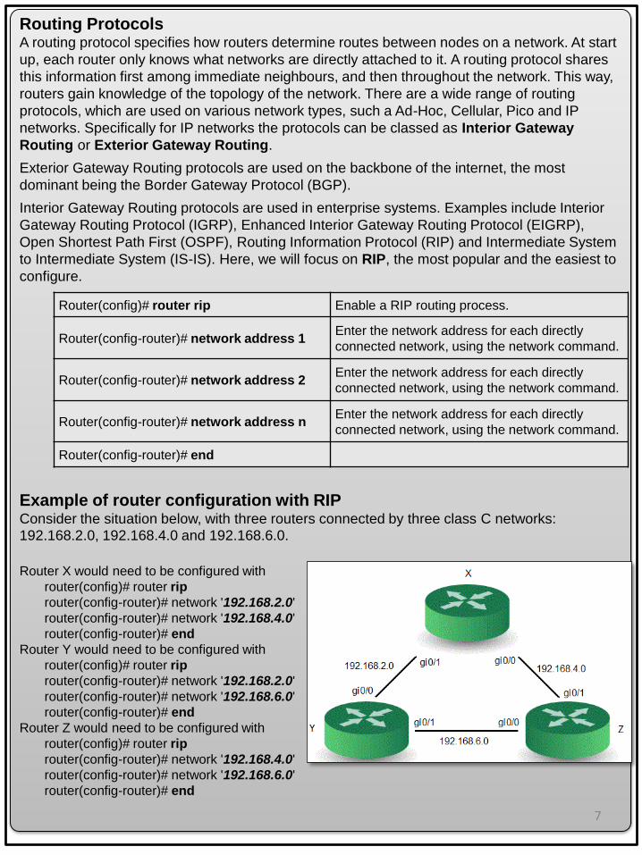
Routing ProtocolsA routing protocol specifies how routers determine routes between nodes on a network. At start
up, each router only knows what networks are directly attached to it. A routing protocol shares
this information first among immediate neighbours, and then throughout the network. This way,
routers gain knowledge of the topology of the network. There are a wide range of routing
protocols, which are used on various network types, such a Ad-Hoc, Cellular, Pico and IP
networks. Specifically for IP networks the protocols can be classed as Interior Gateway
Routing or Exterior Gateway Routing.
Exterior Gateway Routing protocols are used on the backbone of the internet, the most
dominant being the Border Gateway Protocol (BGP).
Interior Gateway Routing protocols are used in enterprise systems. Examples include Interior
Gateway Routing Protocol (IGRP), Enhanced Interior Gateway Routing Protocol (EIGRP),
Open Shortest Path First (OSPF), Routing Information Protocol (RIP) and Intermediate System
to Intermediate System (IS-IS). Here, we will focus on RIP, the most popular and the easiest to
configure.
Example of router configuration with RIPConsider the situation below, with three routers connected by three class C networks: 192.168.2.0, 192.168.4.0 and 192.168.6.0.
Router X would need to be configured with
router(config)# router rip
router(config-router)# network '192.168.2.0'
router(config-router)# network '192.168.4.0'
router(config-router)# end
Router Y would need to be configured with
router(config)# router rip
router(config-router)# network '192.168.2.0'
router(config-router)# network '192.168.6.0'
router(config-router)# end
Router Z would need to be configured with
router(config)# router rip
router(config-router)# network '192.168.4.0'
router(config-router)# network '192.168.6.0'
router(config-router)# end
7

Network Configuration In this section you will configure a small enterprise network to utilise the interior gateway
dynamic routing protocol RIP. For the network topology and router configuration shown below,
complete the two tables.
Network 1 =
192.168.0.0
Network 2 =
172.16.0.0
Network 3 =
11.0.0.0
Network Address 192.168.0.0
Bit Mask (Doted Decimal) 255.255.255.0
Router1 Interface Address gi0/0 192.168.0.1 - -
Router1 Interface Address gi0/1 - -
Router2 Interface Address gi0/0 - -
Router2 Interface Address gi0/1 - -
First Host Address 192.168.0.2
Last Host Address 192.168.0.254
Broadcast Address 192.168.0.255
Device
Namerouter1 router2
Console
access
password
class class
Privileged
exec
password
cisco cisco
Routing
ProtocolRIP RIP
From To IP Address Ping Results
Host A Router1 Interface Address gi0/0
Host A Router2 Interface Address gi0/1
Host A Host B
Host B Router2 Interface Address gi0/0
Host B Router1 Interface Address gi0/1
Host B Host A
straight
crossover

VTLAN3 Velleman LAN Test Network Modular Tester
1. RJ45 socket (send) 6. Receive indicator graph
2. Manual test button (advances step 7. Power switch
by step while in manual test mode) 8. Battery box (backside of the unit)
3. Auto / manual test switch 9. RJ45 socket (receive)
4. RJ45 socket (receive) 10. Receive indicator LEDs
5. Send indicator graph 11. Shield earth indicator LED (GND)
VTLAN3 Velleman LAN Test Network Modular Tester Manual
This device can be used for testing network and telephone
cables (RJ-45, 10 Base-T, Token Ring, RJ11/12 USOC and
coaxial BNC). It can test cables from a distance and in
places that are not easily accessible. It automatically runs
all tests and checks for continuity, open, shorted and crossed
wire pairs.
Testing RJ45 and similar cables
Insert one end in the SEND RJ45 socket (socket marked with
small triangle) and the other in the RECEIVER RJ45 socket.
Switch on the device.
Select the manual or the automatic test mode.
In automatic test mode, the tester will start testing and the LED graph will light from left to
right. In manual mode, push the TEST button to advance a step at a time.
The upper graph represents the input signal; the lower graph represents the output signal. If
they match and are lit in sequence, the cable is OK. If not, refer to the examples below to
pinpoint the error:
Remote Testing
Insert one end in the SEND socket and the other end in the RECEIVER socket or a
terminator.
If the cable is fixed onto the wall or underground and only the jack is available, use an
adapter wire or the RJ45 test wire.
Read the output from the terminator.
Good ConnectionOpen circuit: 2nd
wire is broken
Short-circuit
between 2nd and
3rd wire
Cross connection
between 2nd and
5th wire
9

Fluke 620 LAN Cable Meter
The Fluke 620 LAN Cable Meter is a battery operated, handheld instrument that identifies cable
failures, measures length, and checks the wiring of cables used for Device Net, Control Net,
and Ethernet Local Area Network (LAN) systems. The device tests for incorrect pairing, split
pairs, miswired, shorted and open wires on all twisted pair cables, as well as shorts on coaxial
cables.
Fluke 620 LAN Cable Meter Manual
The cable type is normally printed on the cable. However, all the cable you will be using in the
laboratory is UTP, EIA/TIA 4 pair, CAT5, AWG 24, 100Ω. Set Calibrate to Cable to No.
Turn the rotary switch selector on the tester to the WIRE MAP position. The wire map function
displays which pins on one end of the cable are connected to which pins on the other end.
Press the SETUP button to enter the setup mode, and observe the LCD screen on the tester.
Press the UP or DOWN arrow buttons and ENTER to select an option.
• CABLE. UTP - Unshielded Twisted Pair
• WIRING. EIA/TIA 4PR - Electronic Industries Alliance/Telecoms Industry Association - 4
Pair
• CATEGORY. Category 5
• WIRE SIZE. AWG 24 - American Wire Gauge 24 (0.51054 mm Conductor Diameter)
• CAL to CABLE? Yes
• BEEPING. On
• LCD CONTRAST. 8.
When satisfied that the settings are correct, press the SETUP button to exit setup mode.
Making Tests and Measurements
Three modes can be selected via the the rotary switch selector:-
Wire Map - Displays wiring connections, shorts, opens, and split pairs. Place the near end of
the cable into the RJ45 jack labelled UTP/FTP on the tester. Place the RJ45 - RJ45 female
coupler on the far end of the cable, and then insert the cable identifier into the other side of the
coupler. The wiring of both the near and far end of the cable will be displayed. The top set of
numbers displayed on the LCD screen refers to the near end, and the bottom set of numbers
refers to the far end.
Length - Measures the length of coaxial cables and each pair of twisted pair cable in feet or
meters and tests for anomalies. Place the near end of the cable into the RJ45 jack labelled
UTP/FTP on the tester. Place the RJ45 - RJ45 female coupler on the far end of the cable, and
then insert the cable identifier into the other side of the coupler.
Test - Tests the attached cable and indicates a “pass or fail” based on the parameters specified
for the selected cable. Place the near end of the cable into the RJ45 jack labelled UTP/FTP on
the tester. Place the RJ45 - RJ45 female coupler on the far end of the cable, and then insert the
cable identifier into the other side of the coupler. 10

WEEK 1.13 TEST
Work in groups of four
You have 70 minutes to complete the test
2) Clear both the Router and the Switch of all settings
Router# erase start
Erasing the nvram file system will remove all
configuration files! Continue?
[confirm] <ENTER>
[OK]
Erase of nvram: complete
Router# reload
Proceed with reload? [confirm] <ENTER>
Switch# delete vlan.dat
Switch# erase start-up config
Erasing the nvram file system will remove all
configuration files! Continue?
[confirm] <ENTER>
[OK]
Erase of nvram: complete
Switch# reload
Proceed with reload? [confirm] <ENTER>
3) Construct the Physical Topology
1) Construct four network cables (or better use cables you prepared earlier)
Identify what cable types are required for the topology below and construct the four cables.
Test the cables with the 'VTLAN3 Velleman LAN Test Network Modular Tester' and the 'Fluke
620 LAN Cable Meter'
11

4) Design the logical network (variable subnetting)
5) Configure the router and host computers
The tutor will select one of your group members’ nine digit University identification number.
Use this number to generate four numbers (α,β,γ and δ) which will determine the number of
hosts within four subnets. Replace all zeros from the nine digit number with the number 2.
Counting from the right, the first two digits are α, the third digit is β, the fourth digit is γ and the
fifth digit is δ. For example, for the id number 000643086, α = 86, β = 2, γ = 3 and δ = 4.
Given the class C IP address 192.158.50.0, design an IP addressing scheme that satisfies
the following requirements:
Subnet Number of Hosts
Router Interfaces will
use the first IP address
in the subnet address
block.
1 α
2 β
3 γ
4 δ
Complete the following table:
Subnet 1 Subnet 2 Subnet 3 Subnet 4
Number of Hosts
Network Address
Router Interface Address
First Host Address
Last Host Address
Broadcast Address
Bit Mask (Binary)
Bit Mask (Doted Decimal)
Host computer B and C are on subnet 1, host computer A is on subnet 2. Configure the router
such that:
o Set the device name to test
o Set the console access password to class
o Set the privileged exec password to cisco
o Routing Protocol RIP
12

6) Test for connectivity
Complete the following table:
From To IP Address Ping Results
Host A Gateway
Host A Host B
Host A Host C
Host B Gateway
Host B Host A
Host B Host C
Host C Gateway
Host C Host A
Host C Host B
Fault Detection:
Ask a lecturer to introduce two problems into your network while you look away. Problems can
be either physical or logical. Then, try to solve these problems.
Fault Solution
13
Before you leave the laboratory, you need to upload this test as PDF. You cannot upload later.

(This is a group reflection – you can write it after the test has finished)
Identify the sections of the laboratory you have understood and demonstrate your
understanding - beyond the simple level of completing the laboratory - through cognitive
processes such as analysing, explaining, interpreting, and evaluating. Illustrate, by the use of
examples how the laboratory contributed towards your understanding and your Degree
programme.
For the sections of the laboratory which you struggled with, or were uncertain of, identify why
this was the case. Evaluate the effectiveness of your learning strategy, including factors such
as motivation, preparation, commitment, time management, communication, constraints and
support. With reflection to past experience, identify how you could improve your learning and
performance to overcome the barriers encountered in this laboratory such that they do not
infringe upon the next laboratory you undertake.
With relation to the sections of the laboratory you encountered difficulty with, state how, and
by when you intend to gain competence in these areas.
Critically appraise the laboratory; identify sections you thought were positive, facilitated your
understanding and contributed to your Degree programme; identify sections that require
improvement and state how and why would you change the laboratory to improve the
laboratory for the next year's students.
7) Group Reflection
According to research by accelerated learning specialist Firebrand Training, technology
graduates could more than double their salaries in the first five years of their careers by
adding some of the IT industry's most common technology certifications to their curriculum
vitae. The laboratory you have just completed has drawn from the Cisco Certified Network
Associate (CCNA) certification course which validates an individual's ability to install,
configure, operate, and troubleshoot medium-size route and switched networks, including
implementation and verification of connections to remote sites in a WAN. Certifications are
qualifications developed by leading companies in the field of computing and networking
technologies. They demonstrate that an individual has achieved a high level of competency
and understanding on the technologies that the various companies offer.
For more information on which certification courses are available within the school visit
http://www.cms.gre.ac.uk/cpd/
If you want more information on Cisco certification courses contact Jason Parke.
The equipment you have used today is for medium-size enterprise networks. The school also
has Cisco routers which are used in the backbone of the Internet and Wide Area Networks
(WANs), and Cisco wireless and security equipment which you are able to book out to use if
you wish to pursue the subject area further.
X) Optional: Professional Certification to boost your career
14