Embed Size (px)
Citation preview

ME 24-688 Introduction to CAD/CAE Tools
Week 9 - Lecture
Linear Structural Analysis
ME 24-688 Introduction to CAD/CAE Tools
Lecture Topics
• Finite Element Analysis (FEA) Overview
• FEA Parameters
• FEA Best Practices
• FEA Software Introduction
• Linear Structure Analysis

ME 24-688 Introduction to CAD/CAE Tools
Product Lifecycle – Week 9
RequirementsPortfolio
ManagementConceptual
DesignProduct
Engineering
Manufacturing Engineering
Simulation & Validation
Build & Produce
Test & QualitySales & Distribution
Maintenance & Repair
Disposal & Recycling
ME 24-688 Introduction to CAD/CAE Tools
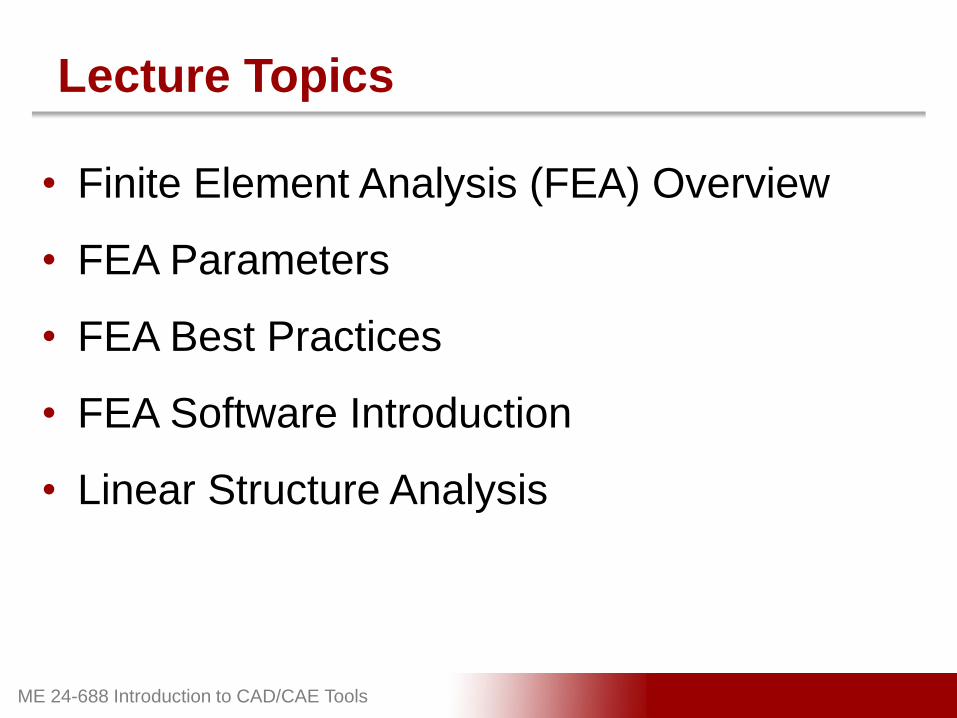
3D Design Use
3D CAD Model
CNC Manufacturing
Rapid Prototyping
Visualization
Simulation / Analysis
Design Detail and Form
Automation

ME 24-688 Introduction to CAD/CAE Tools
What is FEA?
• Finite Element Analysis (FEA) is a
computerized method for predicting how a
real-world object will react to forces,
vibration, heat, and etc. in terms of whether
it will function as planned.

ME 24-688 Introduction to CAD/CAE Tools
FEA Benefits
• Predict Product Performance
• Reduce Raw Materials
• Ensure Optimal Design
• Verification
• Reduce Manual Testing and Prototypes
• Test What-If Scenarios
• Shorten Design Cycle

ME 24-688 Introduction to CAD/CAE Tools
Reasons for Adoption by the Masses
• Better Computing (Faster and Cloud-based)
• Affordable Software
• Easier-to-Use Software
• 3D Design Data has become common.
• The Need to Improve Products Further

ME 24-688 Introduction to CAD/CAE Tools
Who Uses Simulation?
Design Engineer Analysis Engineer

ME 24-688 Introduction to CAD/CAE Tools
FEA Process Overview
1. CAD Model Input
2. Simulation Setup (Pre-process)– Analysis Type
– Material Property Assignment
– Add Constrains (Boundary Conditions)
– Add Loads (Loading Conditions)
– Mesh Generation
3. Solve Simulation
4. Review Results (Post-process)

ME 24-688 Introduction to CAD/CAE Tools
Node Overview
A node is a coordinate location in space
where the Degrees of Freedom (DOFs) and
physical property (stress, strain, temperature,
velocity, etc.) are defined.
ME 24-688 Introduction to CAD/CAE Tools
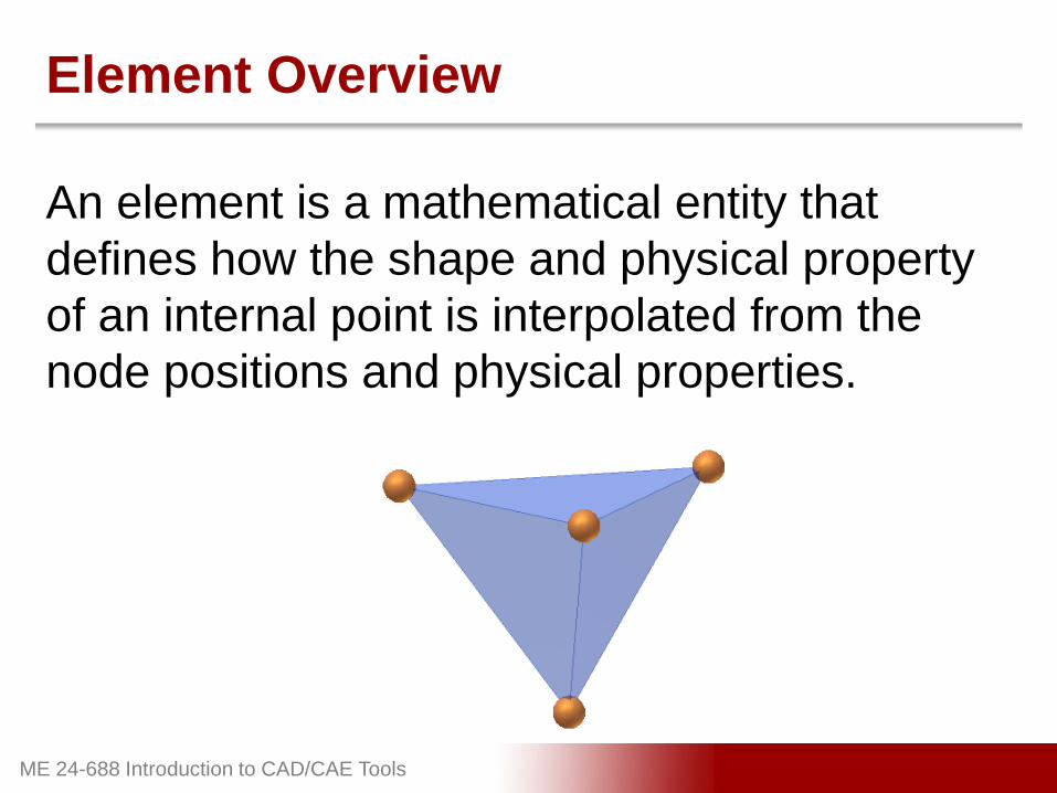
Element Overview
An element is a mathematical entity that
defines how the shape and physical property
of an internal point is interpolated from the
node positions and physical properties.

ME 24-688 Introduction to CAD/CAE Tools
How FEA Works
• Models are defined by nodes and elements
forming a mesh.
• Governing engineering equations (PDE,
ODE) are solved at the nodes and elements.
• A matrix equation, including terms from each
element, is solved.
• Predicts changes within the element.
• The results are plotted on the model using
colors and line plots.

ME 24-688 Introduction to CAD/CAE Tools
Meshed 3D Model Example

ME 24-688 Introduction to CAD/CAE Tools
Types of Elements
• Line Elements– A line connecting 2 nodes only for items like beams and springs.
• 2D Elements– Planar elements with either three or four edges enclosing an area.
• 3D Plates or Shell Elements– Planar elements that are triangular or quadrilateral with a specified
thickness.
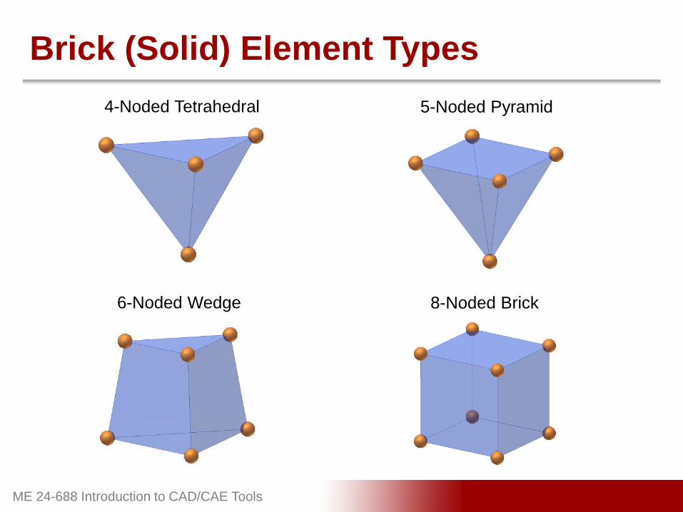
• Brick (Solid) Elements– Enclosed 3D volumes with 4, 5, 6 or 8 corner nodes.
ME 24-688 Introduction to CAD/CAE Tools
Brick (Solid) Element Types
4-Noded Tetrahedral 5-Noded Pyramid
8-Noded Brick6-Noded Wedge

ME 24-688 Introduction to CAD/CAE Tools
Material Assignment
• Material properties define the structure
characteristics of the part.
• Material property information can be found
on the web at www.matweb.com.

ME 24-688 Introduction to CAD/CAE Tools
Constraints
Structural constraints restrict or limit the
displacement of the model mesh nodes.
Floor is Fixed
Constraint
ME 24-688 Introduction to CAD/CAE Tools
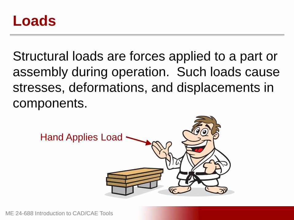
Loads
Structural loads are forces applied to a part or
assembly during operation. Such loads cause
stresses, deformations, and displacements in
components.
Hand Applies Load

ME 24-688 Introduction to CAD/CAE Tools
Contact Conditions
Contact conditions are used to establish
relationships between the nodes of contacting
parts within an assembly.
Contact between
Board and Blocks

ME 24-688 Introduction to CAD/CAE Tools
Simulation Solving
Running or solving the simulation processes
and calculates the results based on the
parameters established.
ME 24-688 Introduction to CAD/CAE Tools
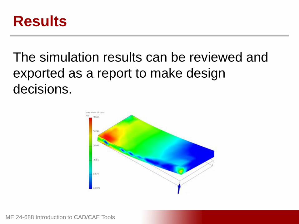
Results
The simulation results can be reviewed and
exported as a report to make design
decisions.

ME 24-688 Introduction to CAD/CAE Tools
Reviewing Results
• Simulation does not always replace the
need for physical testing.
• The engineer / analyst needs to interpret the
results to make final decisions.

ME 24-688 Introduction to CAD/CAE Tools
Analysis Types
• Linear
• Nonlinear
• Thermal
• Natural Frequency – Modal
• Fatigue Analysis
• Fluid Flow
Focus for this week

ME 24-688 Introduction to CAD/CAE Tools
Linear vs. Nonlinear
• Linear– Structure returns to original form
– Small changes in shape stiffness
– No changes in loading direction or magnitude
– Material properties do not change
– Small deformation and strain
• Nonlinear– Geometry changes resulting in stiffness change
– Material deformation that may not return to original form
– Supports changes in load direction and constraint locations
– Support of nonlinear load curves
Focus for this week
ME 24-688 Introduction to CAD/CAE Tools
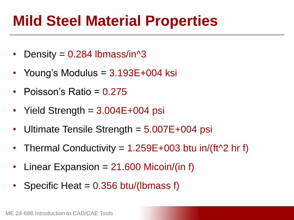
Mild Steel Material Properties
• Density = 0.284 lbmass/in^3
• Young’s Modulus = 3.193E+004 ksi
• Poisson’s Ratio = 0.275
• Yield Strength = 3.004E+004 psi
• Ultimate Tensile Strength = 5.007E+004 psi
• Thermal Conductivity = 1.259E+003 btu in/(ft^2 hr f)
• Linear Expansion = 21.600 Micoin/(in f)
• Specific Heat = 0.356 btu/(lbmass f)

ME 24-688 Introduction to CAD/CAE Tools
Strain
Hardening
Mild Steel Stress Strain CurveS
tress =
Strain =
Yield Strength
(Elastic Limit)
Ultimate Strength
Failure
Necking
Change in Length
Original Length
Are
a
Fo
rce

ME 24-688 Introduction to CAD/CAE Tools
Von Mises Stress
Formula for combining three principal stresses
into an equivalent stress to compare to the
material stress properties.

ME 24-688 Introduction to CAD/CAE Tools
Displacement
• The displacement results show the
magnitude of the model deformation from
the original shape.

ME 24-688 Introduction to CAD/CAE Tools
Safety Factor
Provides a ratio of how much stronger the
object is than it usually needs to be for an
intended load.
Material Yield Strength
Maximum Von Mises StressSafety Factor =
40,000 psi
20,000 psi2 =

ME 24-688 Introduction to CAD/CAE Tools
Convergence (Mesh Independence Study)
Convergence is the process of altering
element sizes in high stress areas to ensure
the specified result criteria has converged.

ME 24-688 Introduction to CAD/CAE Tools
Stress Singularities
A localized high stress area where the stress
becomes infinite resulting distorted results.

ME 24-688 Introduction to CAD/CAE Tools
Best Practices
• Setup simulation to match real world
• Verify material properties
• Use engineering knowledge judgment
• Avoid putting loads on nodes or small edges
• Choose formulation type (Linear / Nonlinear)
• Identify stress singularities
• Ensure your results converge
ME 24-688 Introduction to CAD/CAE Tools
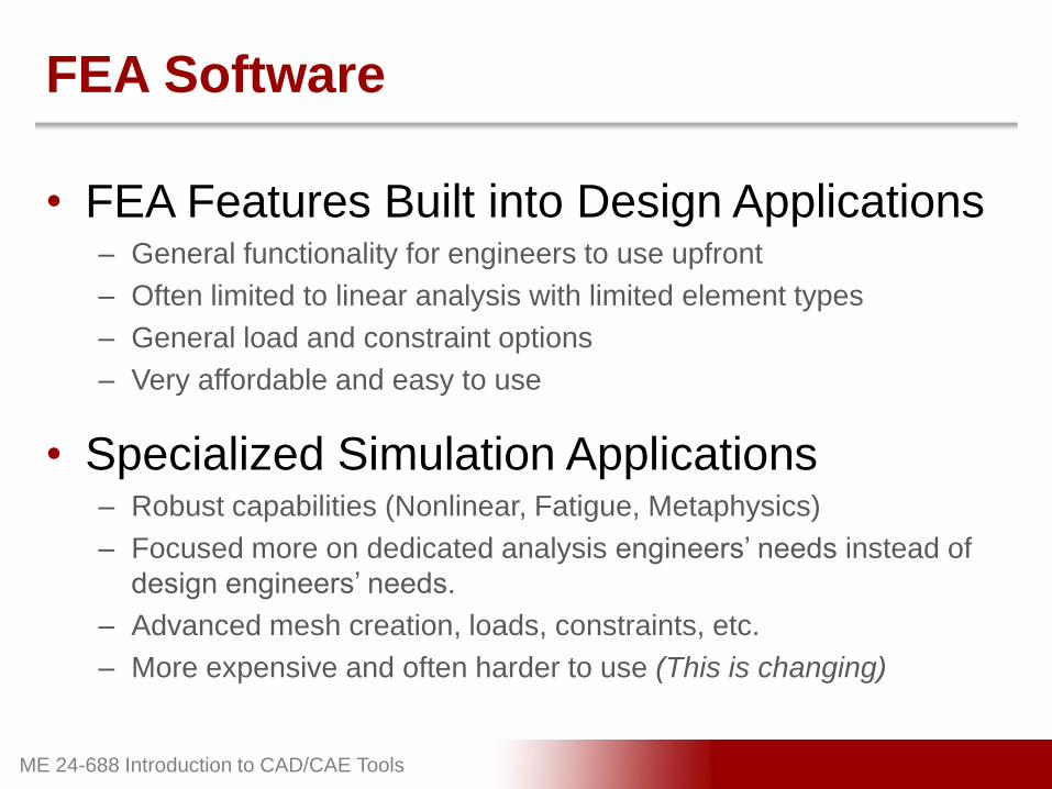
FEA Software
• FEA Features Built into Design Applications– General functionality for engineers to use upfront
– Often limited to linear analysis with limited element types
– General load and constraint options
– Very affordable and easy to use
• Specialized Simulation Applications– Robust capabilities (Nonlinear, Fatigue, Metaphysics)
– Focused more on dedicated analysis engineers’ needs instead of
design engineers’ needs.
– Advanced mesh creation, loads, constraints, etc.
– More expensive and often harder to use (This is changing)

ME 24-688 Introduction to CAD/CAE Tools
Autodesk Inventor Professional
FEA Capability Summary– Linear Analysis
– Tetrahedron Elements Only
– Static and Modal Analysis
– Automatic Mesh Creation
– Frame Analysis (Line Elements)
– General Loads, Constraints, Contacts
ME 24-688 Introduction to CAD/CAE Tools
Computer-Cluster Projects (CP9)

ME 24-688 Introduction to CAD/CAE Tools
Guided Lab Project 1
Guided instructions for assigning loads and
constraints.

ME 24-688 Introduction to CAD/CAE Tools
Guided Lab Project 2
Guided instructions for performing an analysis
on the clamp arm to optimize the design.
ME 24-688 Introduction to CAD/CAE Tools
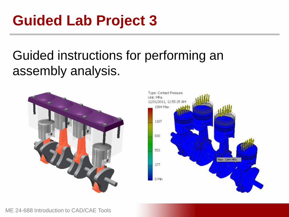
Guided Lab Project 3
Guided instructions for performing an
assembly analysis.
ME 24-688 Introduction to CAD/CAE Tools
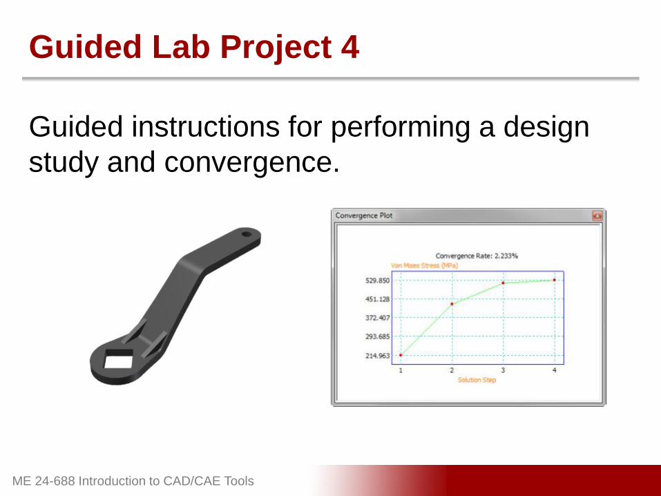
Guided Lab Project 4
Guided instructions for performing a design
study and convergence.

ME 24-688 Introduction to CAD/CAE Tools
Problem Set Assignment
Analyze the bracket to ensure the optimal
design is produced.

ME 24-688 Introduction to CAD/CAE Tools
Demo Topics

ME 24-688 Introduction to CAD/CAE Tools
User Interface
Stress Analysis tab
Stress Analysis panels
Stress Analysis browser
Graphical display

ME 24-688 Introduction to CAD/CAE Tools
Stress Analysis Panels
Manage panel
Materials, Constraints, Loads,
and Contacts panels
Prepare panel
Solve panel
Result, Display, and Report
panels
Settings panel
Exit panel

ME 24-688 Introduction to CAD/CAE Tools
Stress Analysis Browser
Multiple simulations
For a part, features.
For an assembly, parts
Constraints and Loads
Contacts
Mesh settings
Results folder

ME 24-688 Introduction to CAD/CAE Tools
Simulation Properties
Name of the simulation
Single Point design objective
Parametric Dimension design objective
Static Analysis or Modal Analysis
Defaults for the Automatic Contacts tool
ME 24-688 Introduction to CAD/CAE Tools
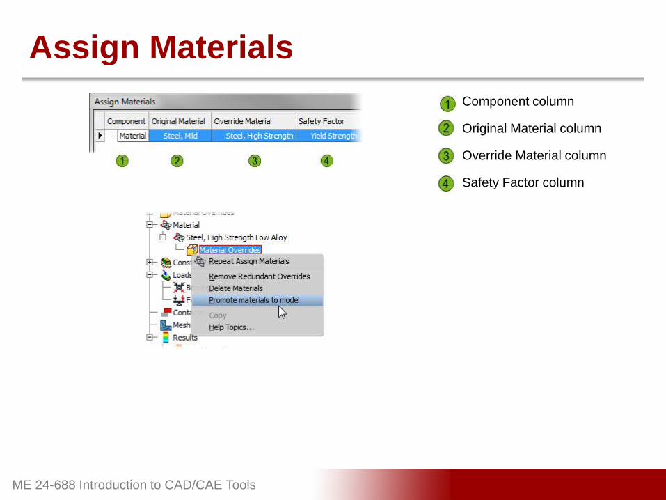
Assign Materials
Component column
Original Material column
Override Material column
Safety Factor column

ME 24-688 Introduction to CAD/CAE Tools
Assign Constraints

ME 24-688 Introduction to CAD/CAE Tools
Assign Loads

ME 24-688 Introduction to CAD/CAE Tools
Assign Loads Cont’d
ME 24-688 Introduction to CAD/CAE Tools
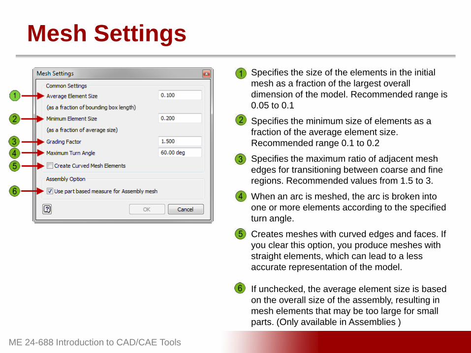
Mesh Settings
Specifies the size of the elements in the initial
mesh as a fraction of the largest overall
dimension of the model. Recommended range is
0.05 to 0.1
Specifies the minimum size of elements as a
fraction of the average element size.
Recommended range 0.1 to 0.2
Specifies the maximum ratio of adjacent mesh
edges for transitioning between coarse and fine
regions. Recommended values from 1.5 to 3.
When an arc is meshed, the arc is broken into
one or more elements according to the specified
turn angle.
Creates meshes with curved edges and faces. If
you clear this option, you produce meshes with
straight elements, which can lead to a less
accurate representation of the model.
If unchecked, the average element size is based
on the overall size of the assembly, resulting in
mesh elements that may be too large for small
parts. (Only available in Assemblies )

ME 24-688 Introduction to CAD/CAE Tools
Automatic Convergence Settings
Specifies the maximum number of refinement
that takes place during convergence.
Specifies when the convergence stops.
Specifies the refinement threshold (between 0 to
1). A zero setting means include all the elements
in the set as candidates for refinement. 1 means
exclude all elements in the set from refinement.
The default is .75, which means, of the elements
with equivalent errors at the top, 25% are subject
to refinements.
Specifies which analysis result to check for
convergence.
A simulation will not converge if there is a stress
singularity. If the singularity is not in an area of
interest or importance, you typically ignore the
stress in that area for the purpose of
convergence.

ME 24-688 Introduction to CAD/CAE Tools
Contacts

ME 24-688 Introduction to CAD/CAE Tools
Contacts Cont’d

ME 24-688 Introduction to CAD/CAE Tools
Results Tools
Animates the displacement
Probe the results at a Particular Node
Adjust the color bar position and scale
Controls the visibility of Probe Labels
Displays the maximum and minimum Labels
Selects the type of color shading
Controls the visibility of Boundary Conditions
Controls the model displacement scale
Generates a report