Embed Size (px)
Citation preview
1
WATER PENETRATION TEST APPARATUS
ME 493 Final Report – Year 2010
Portland State University
Industry Advisor/Sponsor
Bryan HayesMorrison Hershfield
Group Members
Andy ParkLuke Defrees
Andrew WilliamsBrian Pinkstaff
Academic Advisor
Dr. David TurcicPortland State University

2
EXECUTIVE SUMMARY
A small division of Morrison Hershfield, an engineering consulting organization, performs tests
on exterior windows, curtain walls, skylights, and doors for water penetration. It does so
through the use of a spray rack, which is designed to evenly spray water at specified flow rates
(standard ASTM E1105-00) onto each test specimen. Because this standard does not outline
any required design elements other than symmetry, there are potentially unlimited design
possibilities to meet these flow rate requirements. The spray rack that Morrison Hershfield
currently utilizes has a number of design flaws and performance deficiencies that limit
productivity, and produce questionable results.
This capstone project involves addressing these deficiencies, by designing, prototyping, and
testing an original, fully-operational spray rack that meets these standards, and satisfies the
constraints set forth by Morrison Hershfield. At the start of this project, these constraints were
defined in a PDS document, along with a timeline outlining the goals for completing different
stages of the project. This report evaluates the overall success of the project by examining
whether each of the constraints specified in the PDS were met.

3
TABLE OF CONTENTS
Executive Summary…………....………………………………………………………………………... 2
Introduction and Background.……..………………………………………………………..……... 4
Mission Statement.............................................................................................. 5
Main Design Requirements……………………………………………………………………………. 5-8
Final Design….…………….…………………………………………………………………………..…….. 8-11
Evaluation of Design.……….…………………………………………………………………….….….. 12-15
Conclusion…….…………………………………………………………………………………….…….….. 15
Appendices......................................................................................................... 16
A. Assembly Components............................................................................................... 17-21B. Justification of Final Design........................................................................................ 22-34C. Operation Manuals……………………………………………………………………………………………….. 35-36D. Product Data Specification Table............................................................................... 37-38E. House of Quality………................................................................................................. 39F. Part Drawings………………............................................................................................. 40-48G. Bill of Materials.………….............................................................................................. 49-52H. ASTM E 1105-00
Standard.......................................................................................... 53-57
4
INTRODUCTION AND BACKGROUND
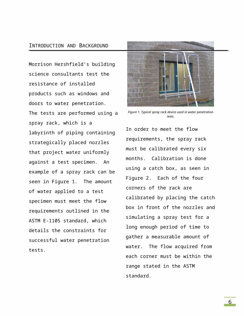
Morrison Hershfield’s building science
consultants test the resistance of installed
products such as windows and doors to water
penetration. The tests are performed using a
spray rack, which is a labyrinth of piping
containing strategically placed nozzles that
project water uniformly against a test
specimen. An example of a spray rack can be
seen in Figure 1. The amount of water
applied to a test specimen must meet the
flow requirements outlined in the ASTM E-
1105 standard, which details the constraints
for successful water penetration tests.
Figure 1. Typical spray rack device used in water penetration tests.
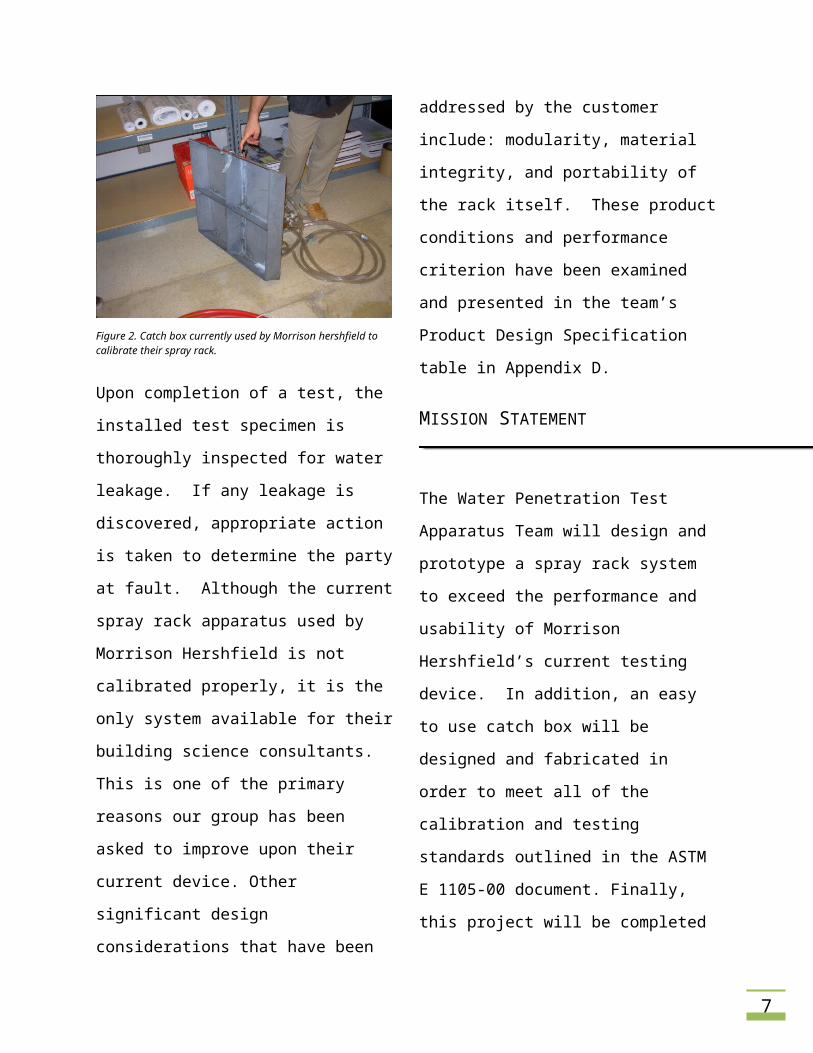
In order to meet the flow requirements, the
spray rack must be calibrated every six
months. Calibration is done using a catch
box, as seen in Figure 2. Each of the four
corners of the rack are calibrated by placing
the catch box in front of the nozzles and
simulating a spray test for a long enough
period of time to gather a measurable
amount of water. The flow acquired from
each corner must be within the range stated
in the ASTM standard.
Figure 2. Catch box currently used by Morrison hershfield to calibrate their spray rack.
Upon completion of a test, the installed test
specimen is thoroughly inspected for water
leakage. If any leakage is discovered,
appropriate action is taken to determine the
party at fault. Although the current spray
rack apparatus used by Morrison Hershfield is
not calibrated properly, it is the only system
available for their building science
consultants. This is one of the primary
reasons our group has been asked to improve
upon their current device. Other significant
design considerations that have been
addressed by the customer include:
5
modularity, material integrity, and portability
of the rack itself. These product conditions
and performance criterion have been
examined and presented in the team’s
Product Design Specification table in
Appendix D.
MISSION STATEMENT
The Water Penetration Test Apparatus Team
will design and prototype a spray rack system
to exceed the performance and usability of
Morrison Hershfield’s current testing device.
In addition, an easy to use catch box will be
designed and fabricated in order to meet all
of the calibration and testing standards
outlined in the ASTM E 1105-00 document.
Finally, this project will be completed on
time, meeting appropriate deadlines, and
within the budget requirements outlined by
Morrison Hershfield.
MAIN DESIGN REQUIREMENTS
In order for this project to be considered
successful, it must meet the following
requirements:
• Meet flow rate requirements of ASTM
standard E 1105-00
• Improve portability and usability of previous
design
• Ensure safety and structural integrity of
design
• Nice aesthetics and professional
appearance
• Is completed within Morrison Hershfield’s
budget
ASTM E 1105-00 Calibration Standards
Meeting the calibration requirements
verifies that the water penetration testing
device performs properly. The key elements
of functionality include a uniform spray
pattern and meeting a target spray rate. As
stated in the standard, the water spray
system shall deliver water uniformly against
the exterior surface of the test specimen at a
minimum rate of 5.0 US gal/ft2-hr. The
acceptable tolerance for the device ranges
from 4-10 US gal/ft2-hr.
Improved Portability and Usability
The ease of use of the water penetration
testing device relies upon required
manpower, setup time, and transportation.
The device should be assembled, transported,
and operated by one person unless it is being
6
used in suspension which would require two
people. The assembly or disassembly of the
spray device should take a maximum of 5
minutes. Most of the parts need to be stock
and easily replaceable in case they break or
malfunction. Finally, it is important that the
device is able to be transported via a compact
passenger car, eliminating the need for a
truck/utility vehicle.
Structural Integrity
The structural integrity of the water
penetration testing device maintains that it
will withstand the stresses acting on it during
operation. The spray device must be
structurally sound when standing on the
ground or in suspension. This ensures the
safety of the users and other individuals
within the proximity of the device during
operation. The device also needs to withstand
the rough handling and abuse of a
construction environment while maintaining
functionality. Because the device will be
regularly exposed to water, all the device
parts need to be corrosion resistant.
Aesthetics
The water penetration testing device should
have a neat and professional appearance.
Other key details include hardware that is
consistent in appearance throughout the
rack.
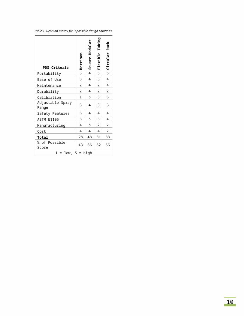
Top-Level Alternative Conceptual Solutions
After brainstorming possible design ideas, the
team evaluated three final design solutions.
A circular rack, flexible tubing rack, and a
square modular rack were compared to the
current Morrison Hershfield model in the
scoring matrix in Table 1 below. The square
modular rack accumulated the highest score.
Table 1: Decision matrix for 3 possible design solutions.
PDS Criteria Mor
rison
Her
shfie
ld
Squa
re M
odul
ar R
ack
Flex
ible
Tub
ing
Rack
Circ
ular
Rac
k
Portability 3 4 5 5
Ease of Use 3 4 3 4
Maintenance 2 4 2 4
Durability 2 4 2 2
Calibration 1 5 3 3
Adjustable Spray Range 3 4 3 3
Safety Features 3 4 4 4
ASTM E1105 3 5 3 4
Manufacturing 4 5 2 2
Cost 4 4 4 2
Total 28 43 31 33
% of Possible Score 43 86 62 66
1 = low, 5 = high
7
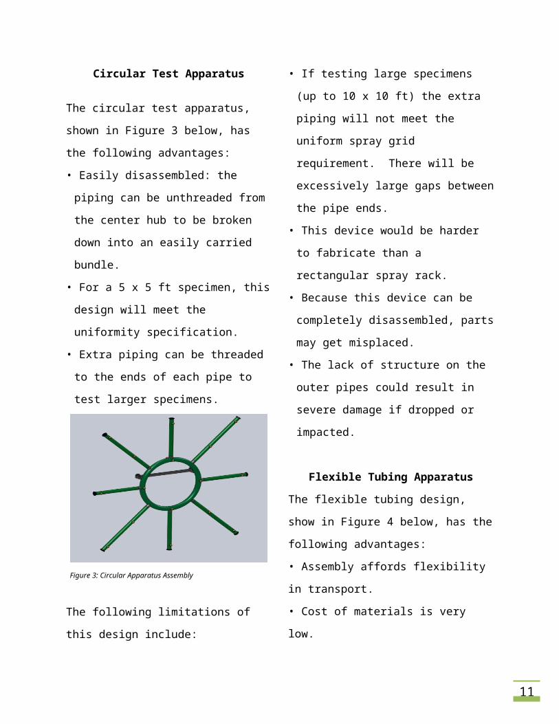
Circular Test Apparatus
The circular test apparatus, shown in Figure 3
below, has the following advantages:
• Easily disassembled: the piping can be un-
threaded from the center hub to be broken
down into an easily carried bundle.
• For a 5 x 5 ft specimen, this design will meet
the uniformity specification.
• Extra piping can be threaded to the ends of
each pipe to test larger specimens.
Figure 3: Circular Apparatus Assembly
The following limitations of this design
include:
• If testing large specimens (up to 10 x 10 ft)
the extra piping will not meet the uniform
spray grid requirement. There will be
excessively large gaps between the pipe
ends.
• This device would be harder to fabricate
than a rectangular spray rack.
• Because this device can be completely
disassembled, parts may get misplaced.
• The lack of structure on the outer pipes
could result in severe damage if dropped or
impacted.
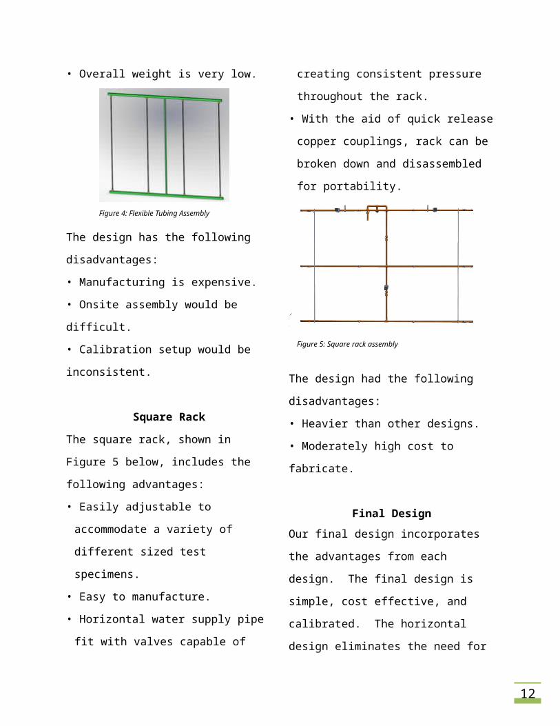
Flexible Tubing Apparatus
The flexible tubing design, show in Figure 4
below, has the following advantages:
• Assembly affords flexibility in transport.
• Cost of materials is very low.
• Overall weight is very low.
Figure 4: Flexible Tubing Assembly
The design has the following disadvantages:
• Manufacturing is expensive.
• Onsite assembly would be difficult.
• Calibration setup would be inconsistent.
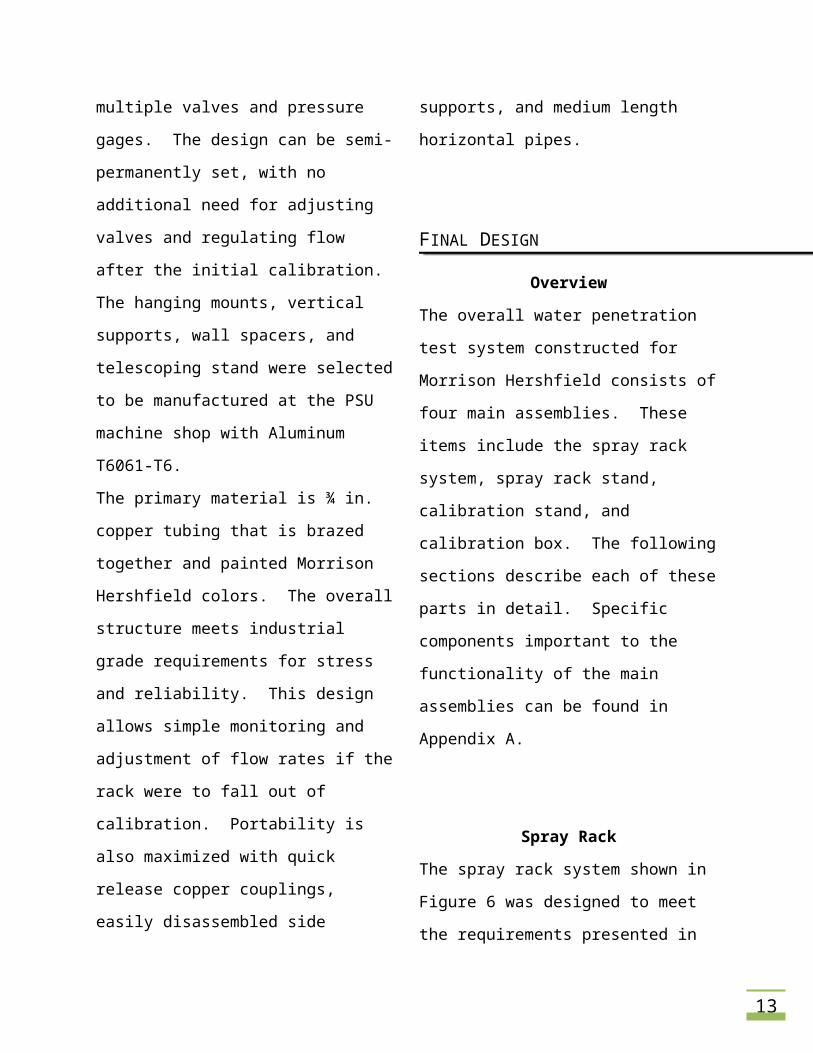
Square Rack
The square rack, shown in Figure 5 below,
includes the following advantages:
• Easily adjustable to accommodate a variety
of different sized test specimens.
8
• Easy to manufacture.
• Horizontal water supply pipe fit with valves
capable of creating consistent pressure
throughout the rack.
• With the aid of quick release copper
couplings, rack can be broken down and
disassembled for portability.
Figure 5: Square rack assembly
The design had the following disadvantages:
• Heavier than other designs.
• Moderately high cost to fabricate.
Final Design
Our final design incorporates the advantages
from each design. The final design is simple,
cost effective, and calibrated. The horizontal
design eliminates the need for multiple valves
and pressure gages. The design can be semi-
permanently set, with no additional need for
adjusting valves and regulating flow after the
initial calibration. The hanging mounts,
vertical supports, wall spacers, and
telescoping stand were selected to be
manufactured at the PSU machine shop with
Aluminum T6061-T6.
The primary material is ¾ in. copper tubing
that is brazed together and painted Morrison
Hershfield colors. The overall structure meets
industrial grade requirements for stress and
reliability. This design allows simple
monitoring and adjustment of flow rates if
the rack were to fall out of calibration.
Portability is also maximized with quick
release copper couplings, easily disassembled
side supports, and medium length horizontal
pipes.
FINAL DESIGN
Overview
The overall water penetration test system
constructed for Morrison Hershfield consists
of four main assemblies. These items include
the spray rack system, spray rack stand,
calibration stand, and calibration box. The
following sections describe each of these
parts in detail. Specific components
important to the functionality of the main
assemblies can be found in Appendix A.
9
Spray Rack
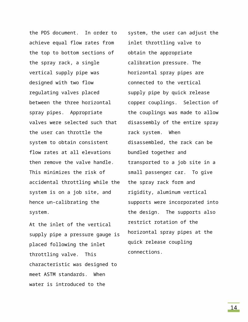
The spray rack system shown in Figure 6 was
designed to meet the requirements
presented in the PDS document. In order to
achieve equal flow rates from the top to
bottom sections of the spray rack, a single
vertical supply pipe was designed with two
flow regulating valves placed between the
three horizontal spray pipes. Appropriate
valves were selected such that the user can
throttle the system to obtain consistent flow
rates at all elevations then remove the valve
handle. This minimizes the risk of accidental
throttling while the system is on a job site,
and hence un-calibrating the system.
At the inlet of the vertical supply pipe a
pressure gauge is placed following the inlet
throttling valve. This characteristic was
designed to meet ASTM standards. When
water is introduced to the system, the user
can adjust the inlet throttling valve to obtain
the appropriate calibration pressure. The
horizontal spray pipes are connected to the
vertical supply pipe by quick release copper
couplings. Selection of the couplings was
made to allow disassembly of the entire spray
rack system. When disassembled, the rack
can be bundled together and transported to a
job site in a small passenger car. To give the
spray rack form and rigidity, aluminum
vertical supports were incorporated into the
design. The supports also restrict rotation of
the horizontal spray pipes at the quick release
coupling connections.
Figure 6: Front view of the final spray rack system.
Small orifice (0.05 in.), 120 deg full cone spray
nozzles were selected to meet the necessary
flow rates outlined in the ASTM standard.
Appendix B shows the necessary calculations
used in nozzle selection. Placing the nozzles 2
ft. apart on the horizontal pipes and 2.25 ft.
vertically, the spray pattern achieves
approximately 30% of overlap between all
adjacent nozzles when the spray rack is
spaced 12 in. away from a test specimen.
Significant spray overlap is necessary to
ensure wetting of all parts of a test specimen.
Telescoping window spacers were designed
to allow proper spacing between the spray
10
rack and a test sample. The telescoping
tubing allows for spacing between 10 and 18
inches. By spacing the rack 18 in. away from
a sample, the water coverage area can be
increased from 33 - 53 ft2 when compared to
12 in. of spacing. Increasing the distance
from the rack to the specimen requires an
increase in system pressure in order to
maintain proper water flow rate
requirements. Hanging mounts were
designed for easy suspension of the spray
rack with either ropes or the spray rack stand.
Spray Rack Stand
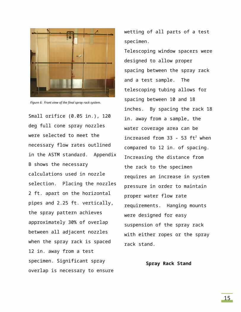
The installed products that Morrison
Hershfield test range from ground level to
multi-story, high rise buildings. Specimens on
the second floor and higher must be tested by
suspending the rack from ropes. Products at
ground level and on the first floor of a
building can be tested using the spray rack
stand illustrated in Figure 7. In order to reach
heights of up to 9 ft. above the ground, thick
walled aluminum telescoping tubing was
selected as the main structure of the stand.
The horizontal tube is held in place by two
sandwiched plates that secure it in the same
plane as the telescoping tubing. Eye bolts
allow for the use of industrial strength
carabiners to make the connection between
the spray rack stand and the hanging mounts
of the spray rack system. The stand can also
be used during calibration to hold the rack
securely on the ground. Because the stand
will be used for these multiple elevations, a
pivoting system was designed at the base to
allow shallow angles of the stand during
calibration and large angles when the stand is
used to elevate the spray rack. Installed on
the bottom of the base plate is a thick rubber
slab to ensure large frictional forces to hold
the stand in place on surfaces like cement or
concrete.
Figure 7. Spray rack stand assembly.
Calibration Stand
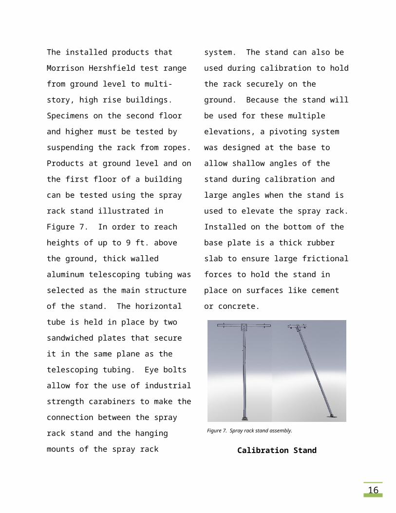
During calibration of the spray rack system,
the calibration box and graduated cylinders
must be placed on a stand to reach the
required locations detailed in the ASTM
standard. The stand designed in Figure 8
11
accomplishes this task by incorporating a
vertical pole held in place by a tripod base.
All materials of the stand were chosen to be
aluminum for corrosion resistance and weight
reduction.
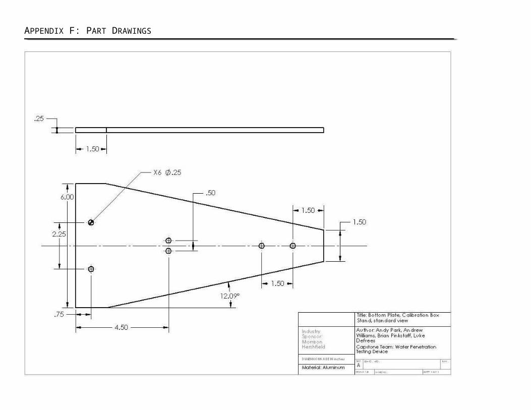
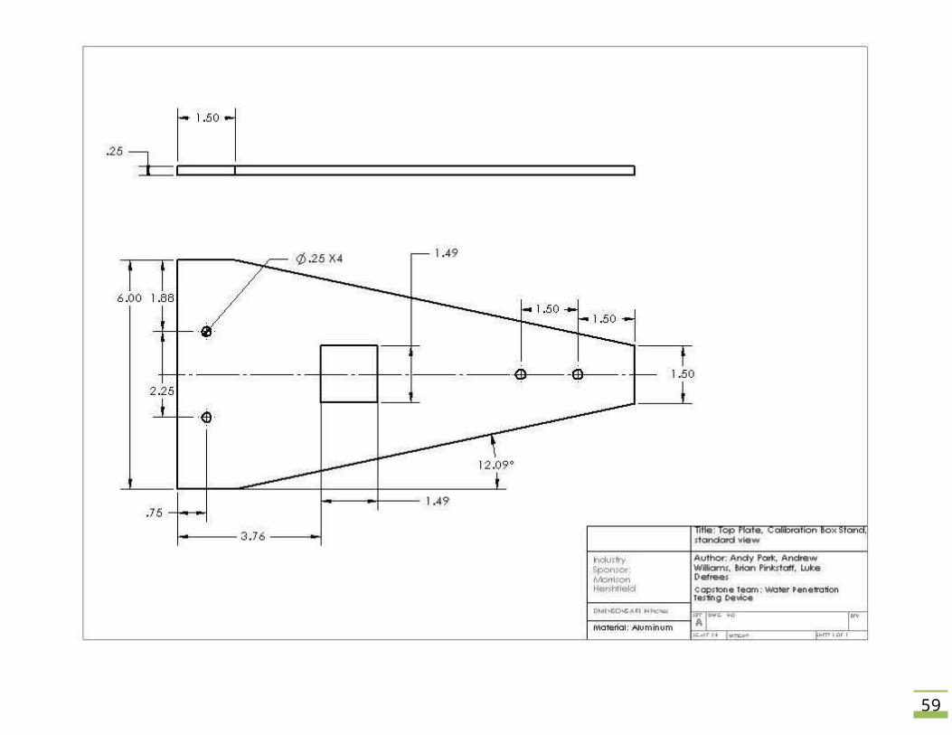
The bottom plates of the stand are 0.25 in.
thick aluminum that are designed so the
vertical tube can protrude through the top
plate, and rest on the bottom plate. An
acrylic block is situated where the tube rests
on the bottom plate and forms a tight fit on
the inside of the vertical tube for further
restriction of sideways movement. This
configuration allows the vertical tube to be
removed from the base for compact storage.
The total height of the stand is 6 ft, which
exceeds the maximum height of the spray
rack system, allowing all possible locations of
the rack to be calibrated.
Figure 8. Calibration stand assembly.
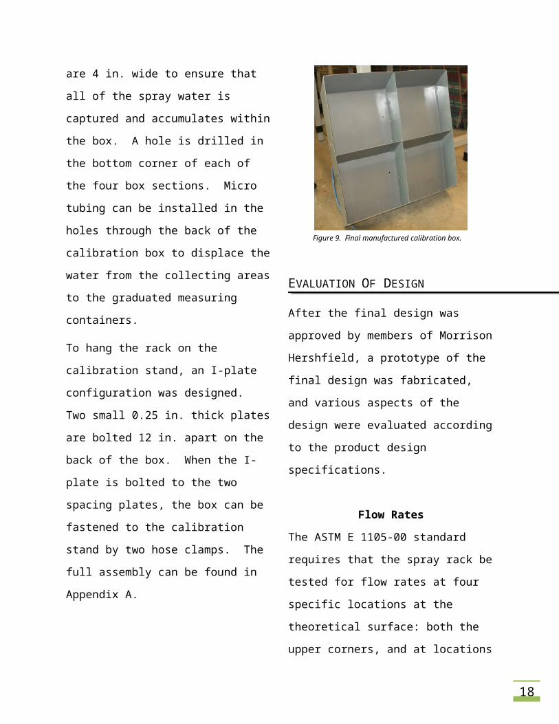
Calibration Box
The catch box in Figure 9 is used to gather the
impinging spray from the rack during
calibration, and was designed according to
the ASTM standard. It is 2 x 2 ft. and
separated into four equal sections. The walls
of the calibration box are 4 in. wide to ensure
that all of the spray water is captured and
accumulates within the box. A hole is drilled
in the bottom corner of each of the four box
sections. Micro tubing can be installed in the
holes through the back of the calibration box
to displace the water from the collecting
areas to the graduated measuring containers.
To hang the rack on the calibration stand, an
I-plate configuration was designed. Two
small 0.25 in. thick plates are bolted 12 in.
apart on the back of the box. When the I-
plate is bolted to the two spacing plates, the
box can be fastened to the calibration stand
by two hose clamps. The full assembly can be
found in Appendix A.
12
Figure 9. Final manufactured calibration box.
EVALUATION OF DESIGN
After the final design was approved by
members of Morrison Hershfield, a prototype
of the final design was fabricated, and various
aspects of the design were evaluated
according to the product design
specifications.
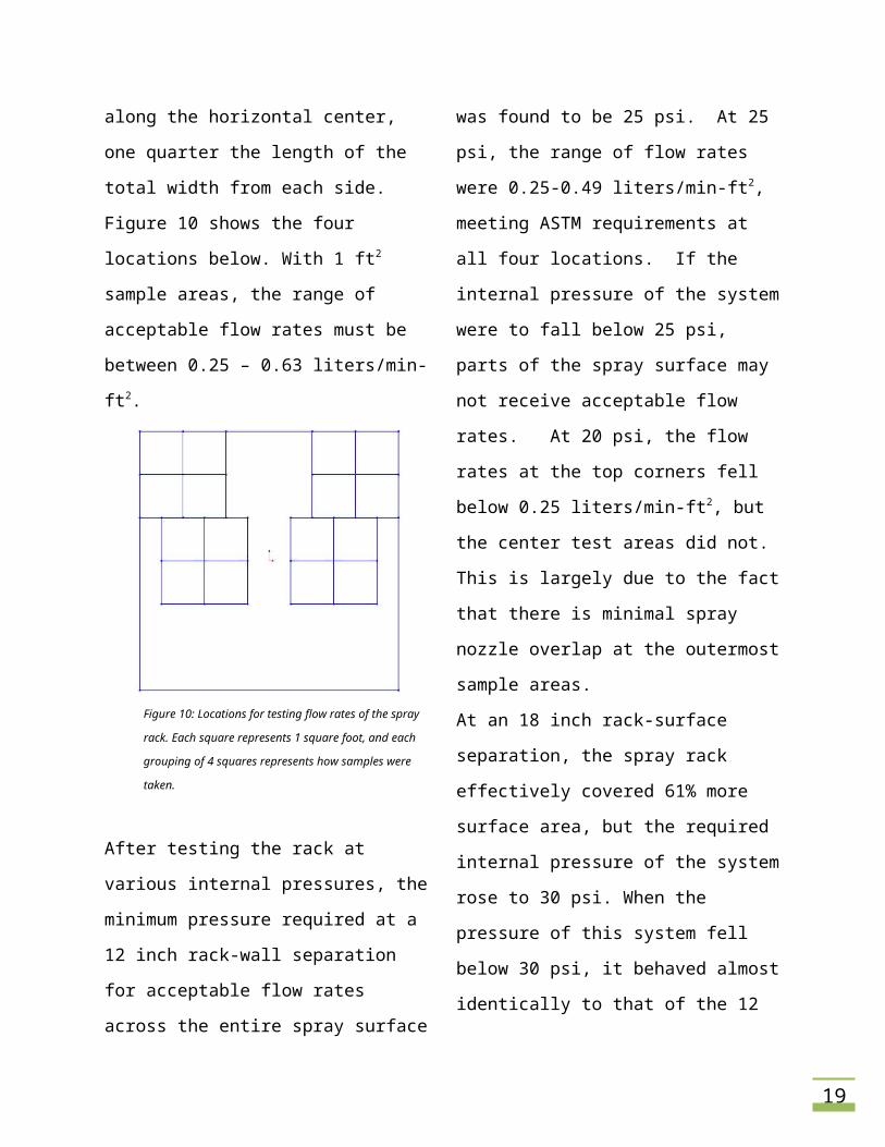
Flow Rates
The ASTM E 1105-00 standard requires that
the spray rack be tested for flow rates at four
specific locations at the theoretical surface:
both the upper corners, and at locations
along the horizontal center, one quarter the
length of the total width from each side.
Figure 10 shows the four locations below.
With 1 ft2 sample areas, the range of
acceptable flow rates must be between 0.25
– 0.63 liters/min-ft2.
Figure 10: Locations for testing flow rates of the spray rack.
Each square represents 1 square foot, and each grouping of
4 squares represents how samples were taken.
After testing the rack at various internal
pressures, the minimum pressure required at
a 12 inch rack-wall separation for acceptable
flow rates across the entire spray surface was
found to be 25 psi. At 25 psi, the range of
flow rates were 0.25-0.49 liters/min-ft2,
meeting ASTM requirements at all four
locations. If the internal pressure of the
system were to fall below 25 psi, parts of the
spray surface may not receive acceptable
flow rates. At 20 psi, the flow rates at the
top corners fell below 0.25 liters/min-ft2, but
the center test areas did not. This is largely
due to the fact that there is minimal spray
nozzle overlap at the outermost sample
areas.
At an 18 inch rack-surface separation, the
spray rack effectively covered 61% more
13
surface area, but the required internal
pressure of the system rose to 30 psi. When
the pressure of this system fell below 30 psi,
it behaved almost identically to that of the 12
inch rack-wall separation system.
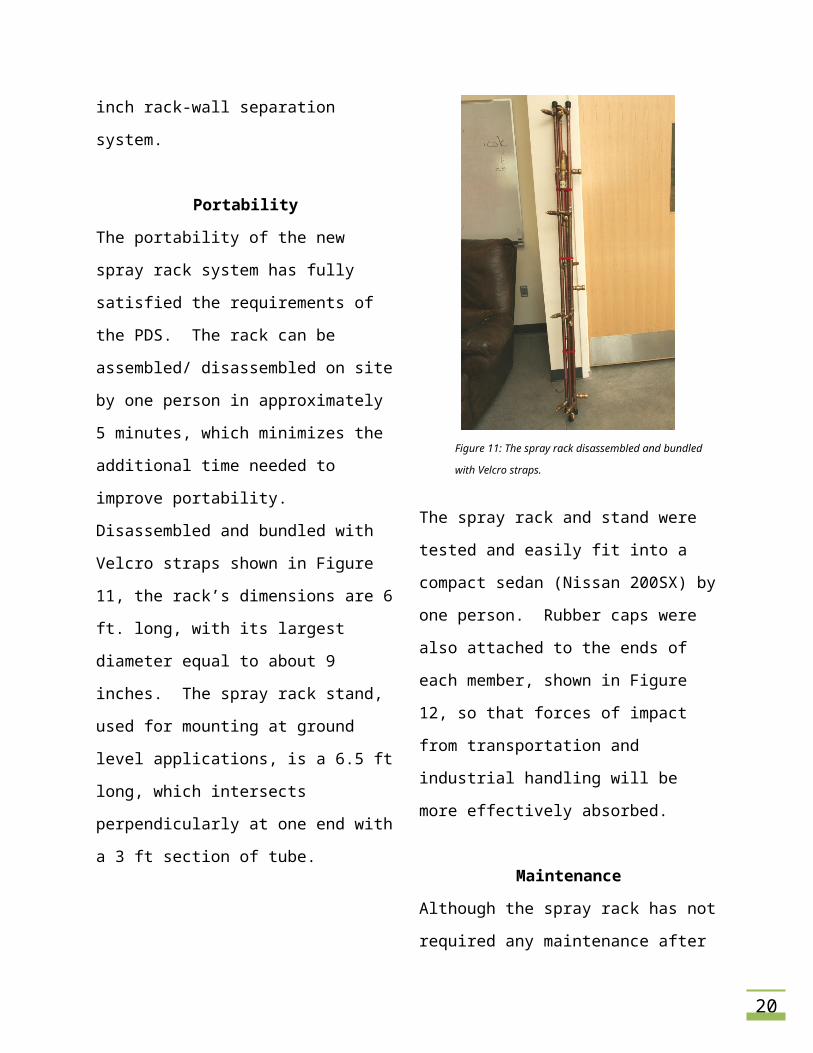
Portability
The portability of the new spray rack system
has fully satisfied the requirements of the
PDS. The rack can be assembled/
disassembled on site by one person in
approximately 5 minutes, which minimizes
the additional time needed to improve
portability.
Disassembled and bundled with Velcro straps
shown in Figure 11, the rack’s dimensions are
6 ft. long, with its largest diameter equal to
about 9 inches. The spray rack stand, used
for mounting at ground level applications, is a
6.5 ft long, which intersects perpendicularly
at one end with a 3 ft section of tube.
Figure 11: The spray rack disassembled and bundled with
Velcro straps.
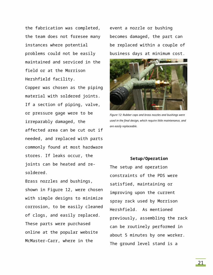
The spray rack and stand were tested and
easily fit into a compact sedan (Nissan 200SX)
by one person. Rubber caps were also
attached to the ends of each member, shown
in Figure 12, so that forces of impact from
transportation and industrial handling will be
more effectively absorbed.
Maintenance
Although the spray rack has not required any
maintenance after the fabrication was
completed, the team does not foresee many
instances where potential problems could not
be easily maintained and serviced in the field
or at the Morrison Hershfield facility.
14
Copper was chosen as the piping material
with soldered joints. If a section of piping,
valve, or pressure gage were to be irreparably
damaged, the affected area can be cut out if
needed, and replaced with parts commonly
found at most hardware stores. If leaks occur,
the joints can be heated and re-soldered.
Brass nozzles and bushings, shown in Figure
12, were chosen with simple designs to
minimize corrosion, to be easily cleaned of
clogs, and easily replaced. These parts were
purchased online at the popular website
McMaster-Carr, where in the event a nozzle
or bushing becomes damaged, the part can
be replaced within a couple of business days
at minimum cost.
Figure 12: Rubber caps and brass nozzles and bushings were used in
the final design, which require little maintenance, and are easily
replaceable.
Setup/Operation
The setup and operation constraints of the
PDS were satisfied, maintaining or improving
upon the current spray rack used by Morrison
Hershfield. As mentioned previously,
assembling the rack can be routinely
performed in about 5 minutes by one worker.
The ground level stand is a single telescoping
tube, which can be controlled by one person.
Once assembled, the rack (without water)
weighs 24.3 lbs, which is far below the PDS
constraint of 50lbs, allowing one person,
instead of two for the current spray rack, to
setup and mount the spray rack at ground
level applications.
The total setup of the rack or mounting of the
rack to the installation at ground level takes
no more than 15 minutes, which satisfies the
PDS requirement. The team was unable to
test the suspension mounting time, due to
limited resources.
Although it is conceivable that the spray rack
be setup and mounted onto roof-suspended
applications by a single worker, the new
design was intended to be operated by two
workers; which is also required for Morrison
Hershfield’s current spray rack. This is due to
the increased degree and quantity of risk
inherent to suspending a spray device of this
size from a large building. Two workers can
15
ensure more stability and accuracy in
suspending this device, and can monitor each
other as well to ensure there are no crucial
oversights that may result in injury or even
death of people below.
The simplicity of operating the rack is
maintained, where only the internal pressure
of the system needs to be monitored. The
coverage area and expandability however are
improved. The current design used by the
project sponsor has a relatively small, fixed
coverage area. With the new design, the
spray rack has a larger coverage area, which
can also be expanded if necessary.
CONCLUSION
The team has designed, fabricated, and
tested a water penetration testing device that
meets or exceeds the requirements set forth
in the product design specifications.
Most importantly, our testing showed that
flow rates of the spray rack at an internal
pressure of 25 psi satisfy the ASTM
requirements. The rack is more easily
transported and covers a larger surface area
than the customer’s current apparatus.
Operation simplicity is maintained, where
only the internal pressure of the device at
steady state needs to be monitored. The
project was also completed in the timeline
specified, meeting acceptable deadlines, and
under budget by $300.
Brian Hayes of Morrison Hershfield has
viewed the prototype and was pleased with
the final design. He commented that all of
the major assemblies were more functional
and appeared more user friendly than their
current device. By meeting or exceeding the
requirements outlined in the PDS, the
customer, and the PSU capstone curriculum,
the design and prototyping of our water
penetration testing apparatus was a success.
16
appendices
17
APPENDIX A: ASSEMBLY COMPONENTS
The following components and parts were used in the main assemblies of the entire spray rack and calibration system.
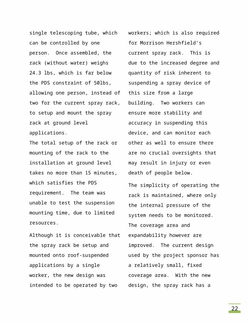
Name: Spray Rack System
Main Assembly: Spray Rack System
Description: The spray rack system is used to uniformly spray water on installed exterior products.
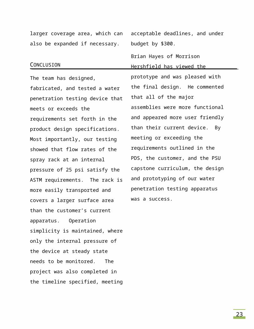
Name: Nozzle Spray Pattern
Main Assembly: Spray Rack System
Description: Spacing the spray rack 12 in. from the test specimen results in the illustrated water spray pattern. Nozzle spacing was selected to achieve approximately 30 percent of spray overlap for proper uniformity of spray onto the specimen.
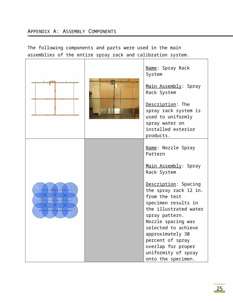
Name: Quick Release Copper Coupling
Main Assembly: Spray Rack System
Description: The couplings were selected to connect the horizontal spray pipes to the vertical supply pipe. Quick release couplings allow for disassembly of the entire spray rack system for ease of transportation.
18
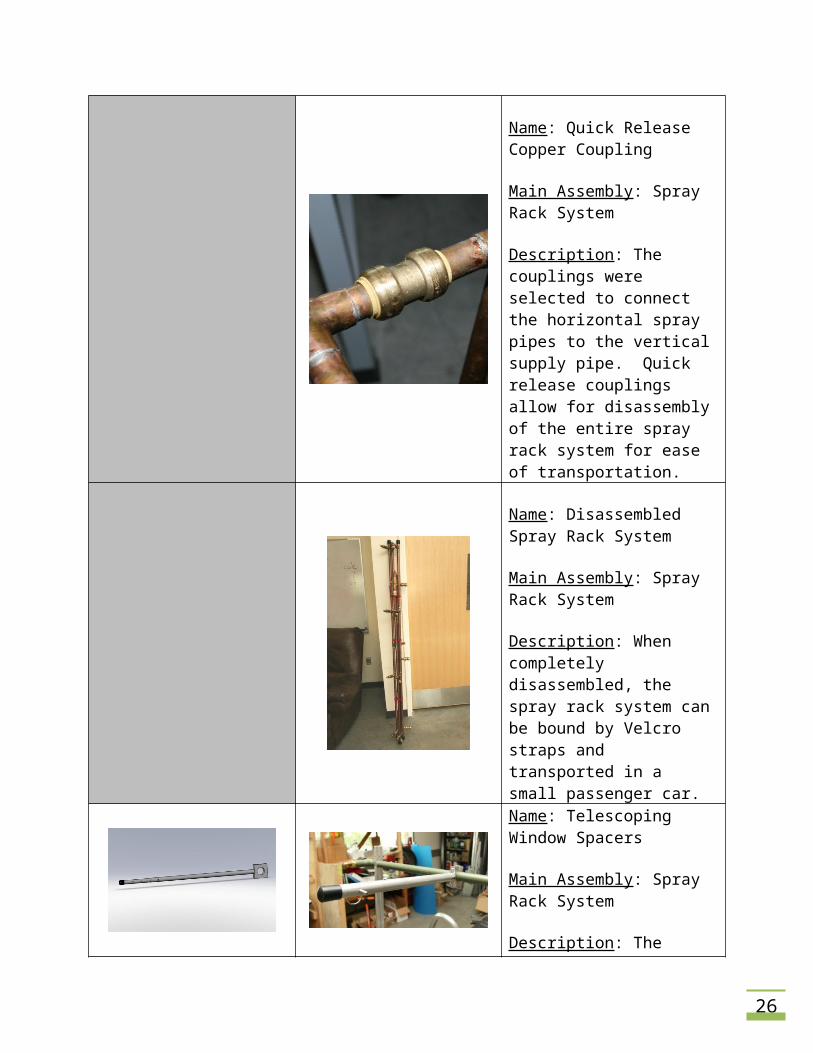
Name: Disassembled Spray Rack System
Main Assembly: Spray Rack System
Description: When completely disassembled, the spray rack system can be bound by Velcro straps and transported in a small passenger car.
Name: Telescoping Window Spacers
Main Assembly: Spray Rack System
Description: The spray rack must be spaced 12 in. away from the test specimen to achieve the cover pattern presented above. Telescoping winder spacers allow the user to achieve this distance, and increase the distance to expand the spray coverage area.
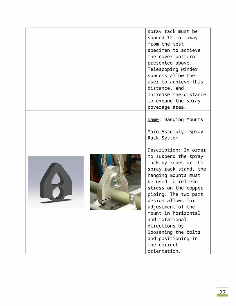
Name: Hanging Mounts
Main Assembly: Spray Rack System
Description: In order to suspend the spray rack by ropes or the spray rack stand, the hanging mounts must be used to relieve stress on the copper piping. The two part design allows for adjustment of the mount in horizontal and rotational directions by loosening the bolts and positioning in the correct orientation.
19
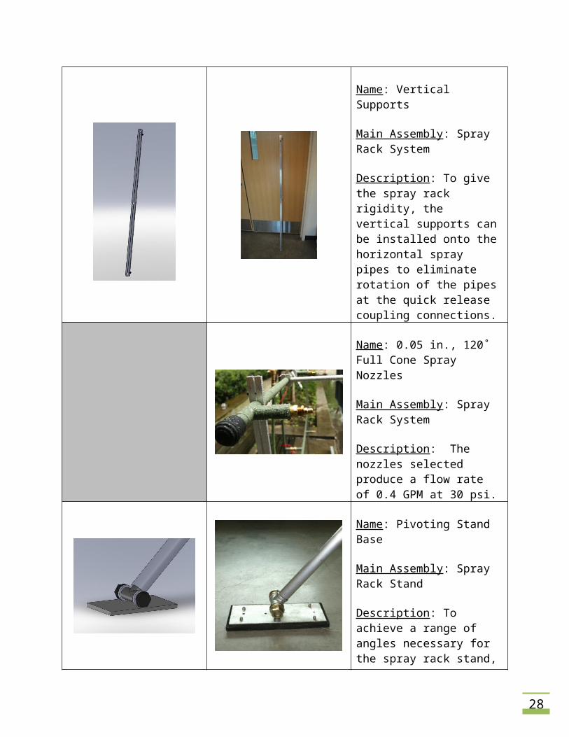
Name: Vertical Supports
Main Assembly: Spray Rack System
Description: To give the spray rack rigidity, the vertical supports can be installed onto the horizontal spray pipes to eliminate rotation of the pipes at the quick release coupling connections.
Name: 0.05 in., 120˚ Full Cone Spray Nozzles
Main Assembly: Spray Rack System
Description: The nozzles selected produce a flow rate of 0.4 GPM at 30 psi.
Name: Pivoting Stand Base
Main Assembly: Spray Rack Stand
Description: To achieve a range of angles necessary for the spray rack stand, the pivoting base was designed to allow the user to easily position the stand and rack where ever it needs to be placed.
20
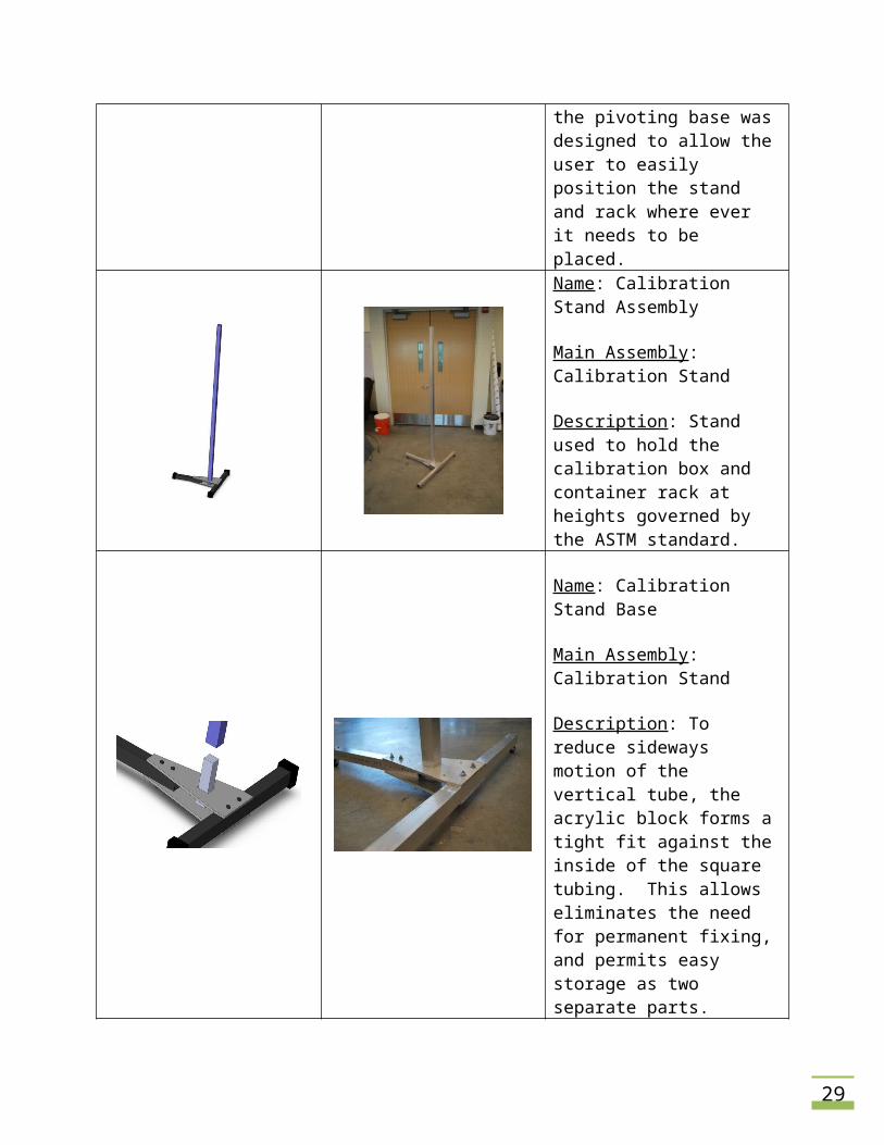
Name: Calibration Stand Assembly
Main Assembly: Calibration Stand
Description: Stand used to hold the calibration box and container rack at heights governed by the ASTM standard.
Name: Calibration Stand Base
Main Assembly: Calibration Stand
Description: To reduce sideways motion of the vertical tube, the acrylic block forms a tight fit against the inside of the square tubing. This allows eliminates the need for permanent fixing, and permits easy storage as two separate parts.
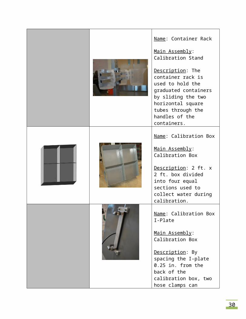
Name: Container Rack
Main Assembly: Calibration Stand
Description: The container rack is used to hold the graduated containers by sliding the two horizontal square tubes through the handles of the containers.
Name: Calibration Box
Main Assembly: Calibration Box
Description: 2 ft. x 2 ft. box divided into four equal sections used to collect water during calibration.
21
Name: Calibration Box I-Plate
Main Assembly: Calibration Box
Description: By spacing the I-plate 0.25 in. from the back of the calibration box, two hose clamps can sufficiently hold the box to the calibration stand.
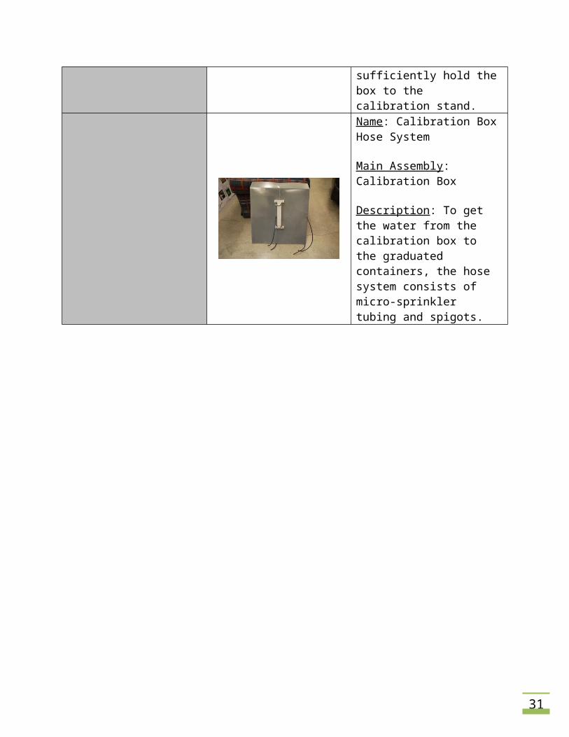
Name: Calibration Box Hose System
Main Assembly: Calibration Box
Description: To get the water from the calibration box to the graduated containers, the hose system consists of micro-sprinkler tubing and spigots.
22
APPENDIX B: JUSTIFICATION OF FINAL DESIGN
To validate the usability and integrity of our final design, the following tests, calculations, and
analyses were completed.
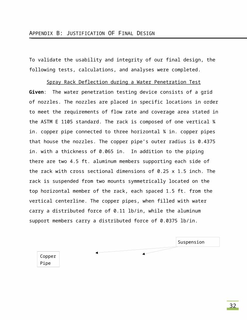
Spray Rack Deflection during a Water Penetration Test
Given: The water penetration testing device consists of a grid of nozzles. The nozzles are
placed in specific locations in order to meet the requirements of flow rate and coverage area
stated in the ASTM E 1105 standard. The rack is composed of one vertical ¾ in. copper pipe
connected to three horizontal ¾ in. copper pipes that house the nozzles. The copper pipe’s
outer radius is 0.4375 in. with a thickness of 0.065 in. In addition to the piping there are two
4.5 ft. aluminum members supporting each side of the rack with cross sectional dimensions of
0.25 x 1.5 inch. The rack is suspended from two mounts symmetrically located on the top
horizontal member of the rack, each spaced 1.5 ft. from the vertical centerline. The copper
pipes, when filled with water carry a distributed force of 0.11 lb/in, while the aluminum support
members carry a distributed force of 0.0375 lb/in.
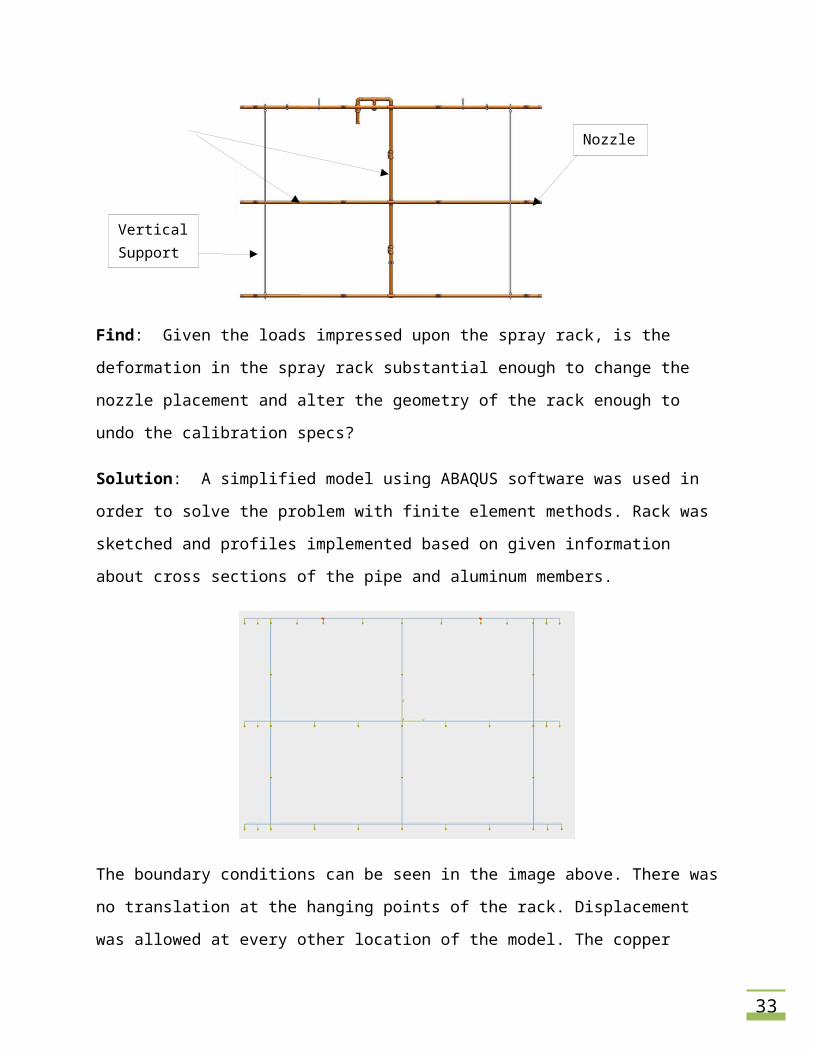
Find: Given the loads impressed upon the spray rack, is the deformation in the spray rack
substantial enough to change the nozzle placement and alter the geometry of the rack enough
to undo the calibration specs?
Nozzle
Vertical Support
Copper Pipe
Suspension Location
23
Solution: A simplified model using ABAQUS software was used in order to solve the problem
with finite element methods. Rack was sketched and profiles implemented based on given
information about cross sections of the pipe and aluminum members.
The boundary conditions can be seen in the image above. There was no translation at the
hanging points of the rack. Displacement was allowed at every other location of the model. The
copper pipes that channel the water had a downward load of 0.11 lb/in and the aluminum
members had applied forces of 0.0375 lb/in.
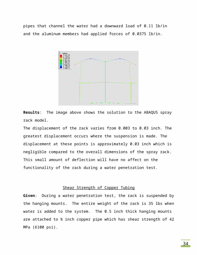
Results: The image above shows the solution to the ABAQUS spray rack model.
The displacement of the rack varies from 0.003 to 0.03 inch. The greatest displacement occurs
where the suspension is made. The displacement at these points is approximately 0.03 inch

24
which is negligible compared to the overall dimensions of the spray rack. This small amount of
deflection will have no affect on the functionality of the rack during a water penetration test.
Shear Strength of Copper Tubing
Given: During a water penetration test, the rack is suspended by the hanging mounts. The
entire weight of the rack is 35 lbs when water is added to the system. The 0.5 inch thick
hanging mounts are attached to ¾ inch copper pipe which has shear strength of 42 MPa (6100
psi).
Find: Will the copper piping fail in shear due to the weight of the entire rack during a water
penetration test?
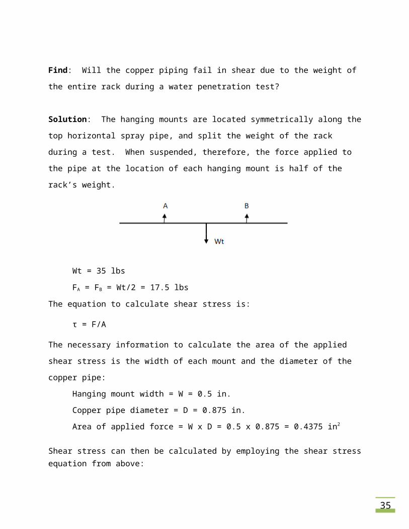
Solution: The hanging mounts are located symmetrically along the top horizontal spray pipe,
and split the weight of the rack during a test. When suspended, therefore, the force applied to
the pipe at the location of each hanging mount is half of the rack’s weight.
Wt = 35 lbs
FA = FB = Wt/2 = 17.5 lbs
The equation to calculate shear stress is:
τ = F/A
The necessary information to calculate the area of the applied shear stress is the width of each
mount and the diameter of the copper pipe:
Hanging mount width = W = 0.5 in.
Copper pipe diameter = D = 0.875 in.
Area of applied force = W x D = 0.5 x 0.875 = 0.4375 in2
25
Shear stress can then be calculated by employing the shear stress equation from above:
τ = 17.5 lb / 0.4375 in2 = 40 psi
Results: The shear stress developed where the hanging mounts are fastened to the copper
piping is 40 psi. The shear strength of the copper is 6100 psi which is much higher than the
stress impinging on the pipe at the hanging mounts. Shear stress developed by the hanging
mounts during a test, therefore, will not exceed the rack’s material constraints.
Stress Analysis of Hanging Mounts
Given: A ¾ inch diameter copper pipe spray rack with a weight of 35 lbs (weight includes
water, hardware, vertical supports, and valves). The pipe has a thickness of 0.065 inch. Mounts
are fastened on the top pipe of the rack, spaced 3 ft. apart uniformly from the vertical line of
symmetry. The material of the hanging mounts is T6061-T6 aluminum with a thickness of 0.5
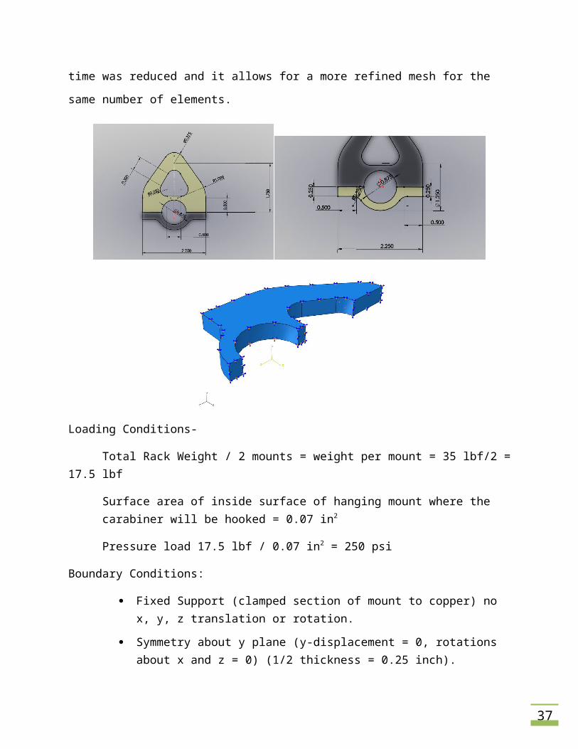
inch. The dimensions for the profile of the mounts are listed below.
Find: Determine the Von Mises stress in the hanging mount, and determine the factor of safety.
Solution: C3D8I: An 8-node linear brick, incompatible mode elements.
Using a finite element software package such as ABAQUS, the analysis can be performed to
determine the static stress on the hanging mount. Taking advantage of symmetry, the
computation time was reduced and it allows for a more refined mesh for the same number of
elements.
26
Loading Conditions-
Total Rack Weight / 2 mounts = weight per mount = 35 lbf/2 = 17.5 lbf
Surface area of inside surface of hanging mount where the carabiner will be hooked = 0.07 in2
Pressure load 17.5 lbf / 0.07 in2 = 250 psi
Boundary Conditions:
Fixed Support (clamped section of mount to copper) no x, y, z translation or rotation.
Symmetry about y plane (y-displacement = 0, rotations about x and z = 0) (1/2 thickness = 0.25 inch).
Symmetry about the x plane, half width (x-displacement = 0, rotations about y and z = 0).
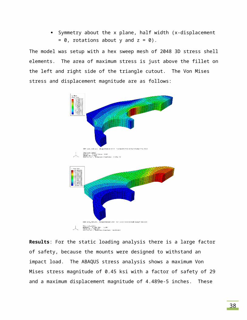
The model was setup with a hex sweep mesh of 2048 3D stress shell elements. The area of
maximum stress is just above the fillet on the left and right side of the triangle cutout. The Von
Mises stress and displacement magnitude are as follows:
27
Results: For the static loading analysis there is a large factor of safety, because the mounts
were designed to withstand an impact load. The ABAQUS stress analysis shows a maximum
Von Mises stress magnitude of 0.45 ksi with a factor of safety of 29 and a maximum
displacement magnitude of 4.489e-5 inches. These mounts are designed to be able to
withstand the stresses applied by the total weight of the rack, water, hardware, and vertical
supporting mounts under a static load.
Spray Nozzle Selection
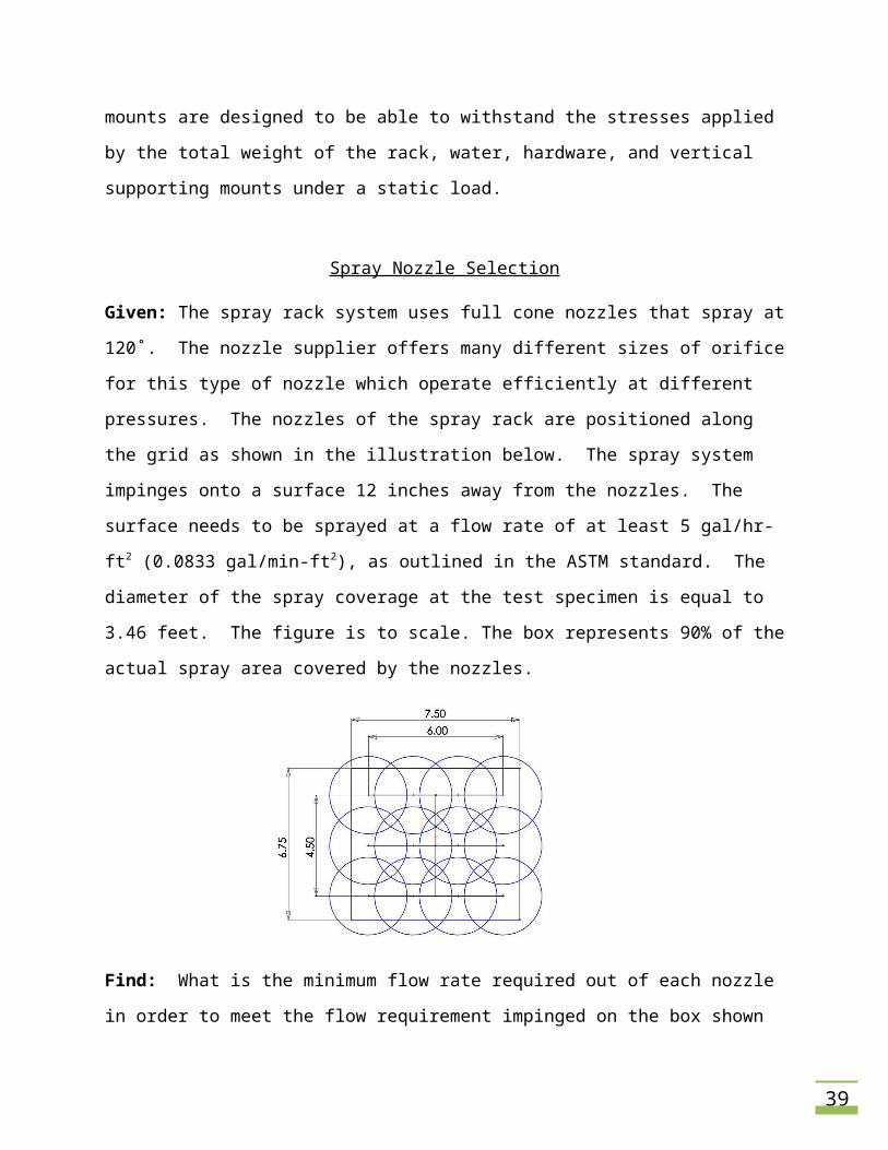
Given: The spray rack system uses full cone nozzles that spray at 120˚. The nozzle supplier
offers many different sizes of orifice for this type of nozzle which operate efficiently at different
pressures. The nozzles of the spray rack are positioned along the grid as shown in the
illustration below. The spray system impinges onto a surface 12 inches away from the nozzles.
28
The surface needs to be sprayed at a flow rate of at least 5 gal/hr-ft2 (0.0833 gal/min-ft2), as
outlined in the ASTM standard. The diameter of the spray coverage at the test specimen is
equal to 3.46 feet. The figure is to scale. The box represents 90% of the actual spray area
covered by the nozzles.
Find: What is the minimum flow rate required out of each nozzle in order to meet the flow
requirement impinged on the box shown in the figure. Use this information to choose the most
appropriate spray nozzle selection for the rack.
Solution: Area of spray coverage = A = length*height = 6.75*6 = 40.5 ft2.
Total flow rate for this coverage area = 5 gal/hr-ft2 * A = 202.5 gal/hr (3.375 gal/min)
With the total flow rate necessary to meet the constraints in the ASTM standard, the amount of
water exiting each nozzle can be calculated by:
Total flow Rate / # of nozzles
(3.375 gal/min)/12 nozzles = 0.281 gal/min-nozzle
Because the area of the box is smaller than area covered by nozzles, the flow rate must be
adjusted so that it sprays the entire spray area at the minimum required rate; assume a 90 %
adjustment factor.
Required flow rate from each nozzle at 25 psi = (Flow rate/nozzle) / 0.90
(0.281 gal/min)/0.90 = 0.313gal/min.
29
Conclusion: An acceptable flow rate for each nozzle is approximately 0.31 gal/min. Based on
the supplier’s selection of nozzles, for an inlet pressure of 25 psi and a required flow rate of
0.32 gal/min, the recommended nozzles are 1/8 inch pipe size with an orifice diameter of 0.05
inch. These nozzles can produce 0.3 gal/min at 20 psi and 0.5 gal/min at 40 psi, making them
the most appropriate nozzles selection.
Horizontal Pressure Differences in the Spray Rack
Given: Uniformity of spray rates is required along the horizontal spray pipes of the rack as
detailed in the ASTM standard. Junction and friction pressure losses that occur within the
piping will affect the spray rates as the flow moves further from the inlet water supply. A test
rack was made of a 6 ft. long, ¾ inch PVC pipe with drilled orifices simulating nozzle spray
diameters. The inlet water pressure was 40 psi and produced a flow rate of 3.2 GPM.
Find: Determine whether or not there is sufficient evidence of a difference in flow rates exiting
the orifices along the horizontal spray pipe.
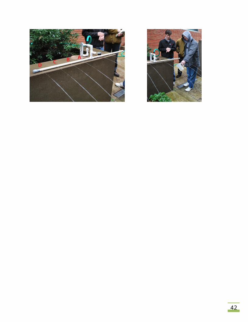
Results: To test the differences in flow rates along the horizontal pipe, an experiment was
devised to complete the task. Four equally spaced small orifices were drilled into the pipe 9
inches apart on each side of the horizontal center. A graduated container was used to gather
water for 1 minute from each orifice. Two different trials of data were collected for each
orifice.
30
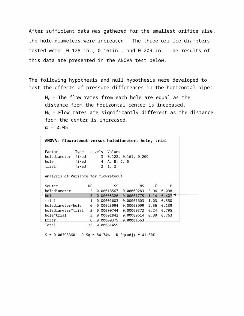
After sufficient data was gathered for the smallest orifice size, the hole diameters were
increased. The three orifice diameters tested were: 0.128 in., 0.161in., and 0.209 in. The
results of this data are presented in the ANOVA test below.
The following hypothesis and null hypothesis were developed to test the effects of pressure differences in the horizontal pipe:
Ho = The flow rates from each hole are equal as the distance from the horizontal center is increased.HA = Flow rates are significantly different as the distance from the center is increased.α = 0.05
ANOVA: flowrateout versus holediameter, hole, trial
Factor Type Levels Valuesholediameter fixed 3 0.128, 0.161, 0.209hole fixed 4 A, B, C, Dtrial fixed 2 1, 2
Analysis of Variance for flowrateout
Source DF SS MS F Pholediameter 2 0.00018567 0.00009283 5.94 0.038hole 3 0.00005326 0.00001775 1.14 0.407trial 1 0.00001603 0.00001603 1.03 0.350holediameter*hole 6 0.00023994 0.00003999 2.56 0.139holediameter*trial 2 0.00000744 0.00000372 0.24 0.795hole*trial 3 0.00001842 0.00000614 0.39 0.763Error 6 0.00009379 0.00001563Total 23 0.00061455
S = 0.00395360 R-Sq = 84.74% R-Sq(adj) = 41.50%
32
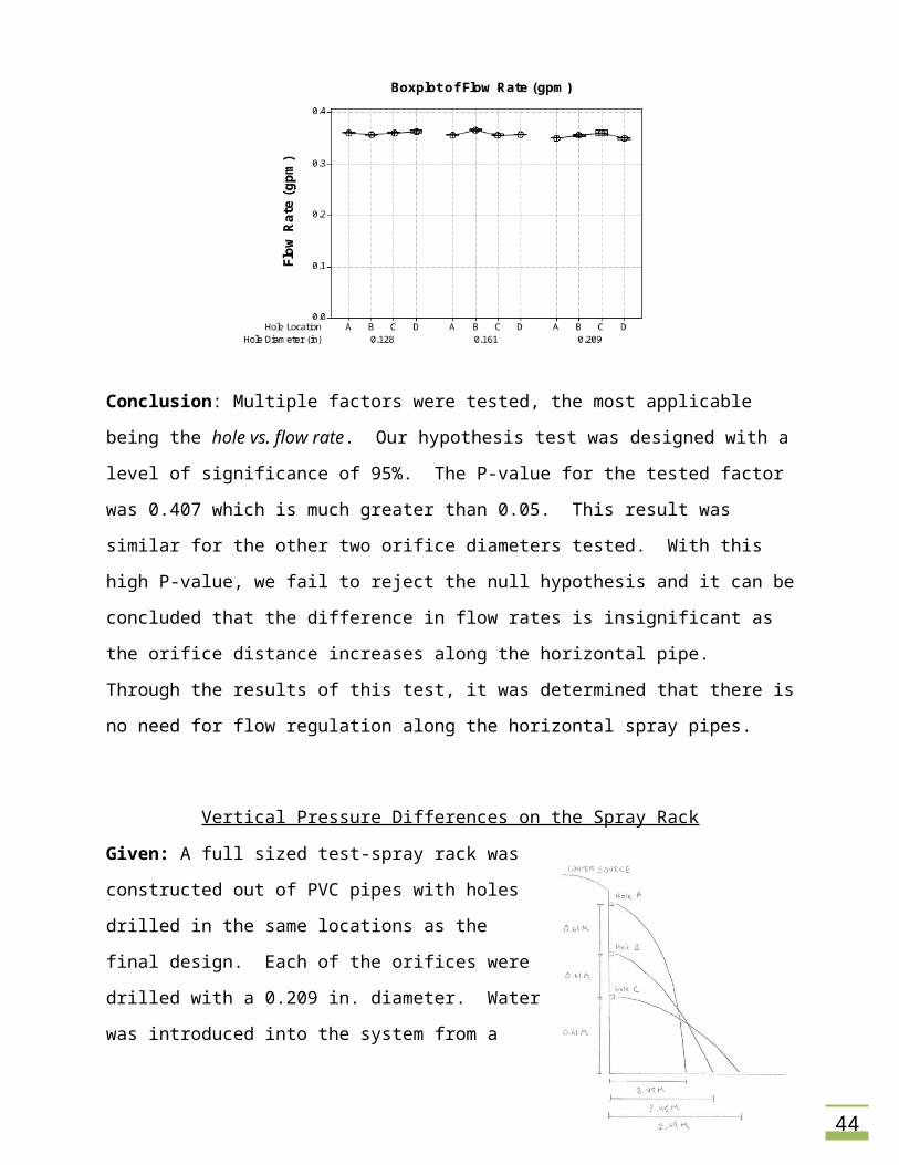
Conclusion: Multiple factors were tested, the most applicable being the hole vs. flow rate. Our
hypothesis test was designed with a level of significance of 95%. The P-value for the tested
factor was 0.407 which is much greater than 0.05. This result was similar for the other two
orifice diameters tested. With this high P-value, we fail to reject the null hypothesis and it can
be concluded that the difference in flow rates is insignificant as the orifice distance increases
along the horizontal pipe. Through the results of this test, it was determined that there is no
need for flow regulation along the horizontal spray pipes.
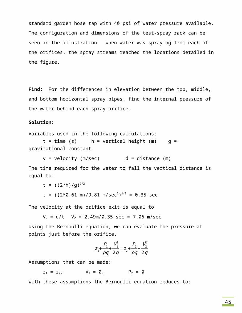
Vertical Pressure Differences on the Spray Rack
Given: A full sized test-spray rack was constructed out of
PVC pipes with holes drilled in the same locations as the
final design. Each of the orifices were drilled with a 0.209
in. diameter. Water was introduced into the system from a
standard garden hose tap with 40 psi of water pressure
available. The configuration and dimensions of the test-
spray rack can be seen in the illustration. When water was
spraying from each of the orifices, the spray streams
reached the locations detailed in the figure.
Find: For the differences in elevation between the top, middle, and bottom horizontal spray
pipes, find the internal pressure of the water behind each spray orifice.
Solution:
Variables used in the following calculations:t = time (s) h = vertical height (m) g = gravitational constant
v = velocity (m/sec) d = distance (m)
The time required for the water to fall the vertical distance is equal to:
t = ((2*h)/g)1/2
t = ((2*0.61 m)/9.81 m/sec2)1/2 = 0.35 sec
The velocity at the orifice exit is equal to
33
V2 = d/t V2 = 2.49m/0.35 sec = 7.06 m/sec
Using the Bernoulli equation, we can evaluate the pressure at points just before the orifice.
z1+P1ρg
+V 12
2g=z2+
P2ρg
+V 22
2g
Assumptions that can be made:
z1 = z2, V1 = 0, P2 = 0
With these assumptions the Bernoulli equation reduces to:
P1=V 22 ρ2
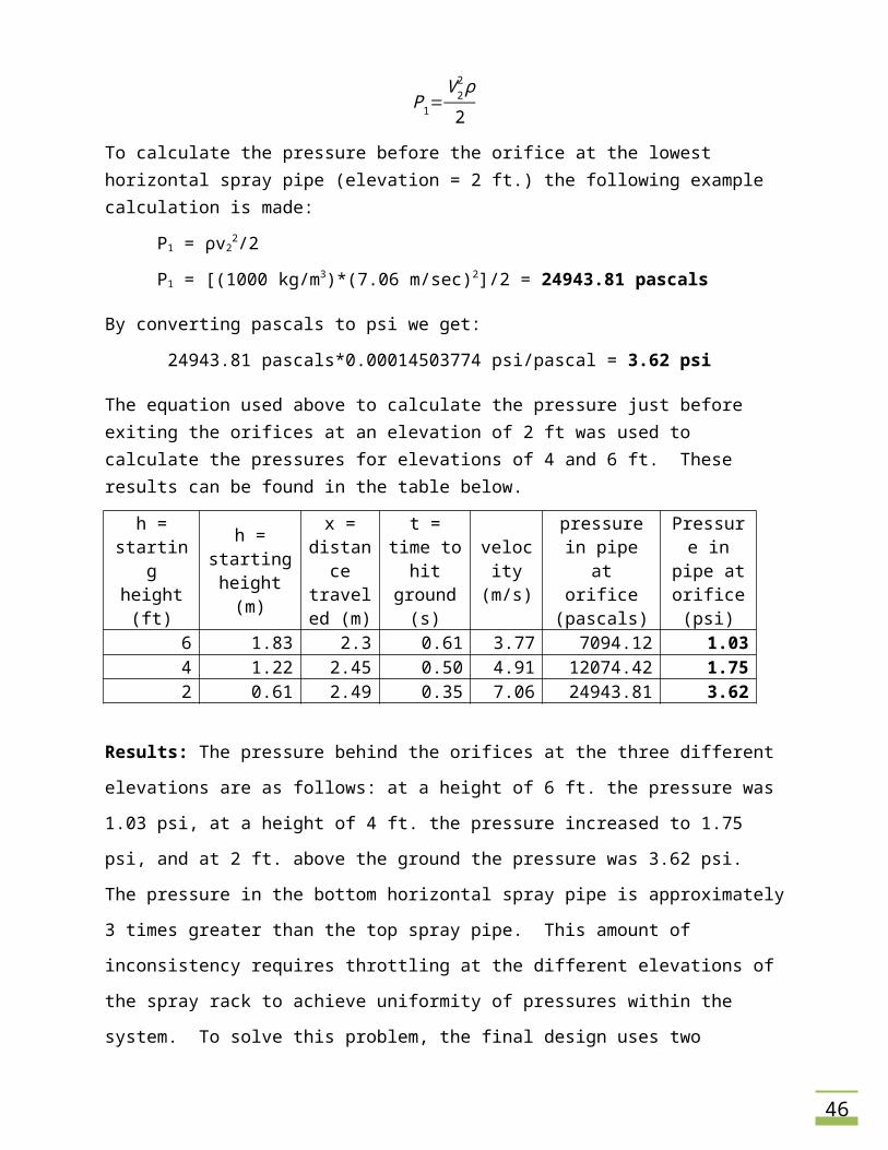
To calculate the pressure before the orifice at the lowest horizontal spray pipe (elevation = 2 ft.) the following example calculation is made:
P1 = ρv22/2
P1 = [(1000 kg/m3)*(7.06 m/sec)2]/2 = 24943.81 pascals
By converting pascals to psi we get:
24943.81 pascals*0.00014503774 psi/pascal = 3.62 psi
The equation used above to calculate the pressure just before exiting the orifices at an elevation of 2 ft was used to calculate the pressures for elevations of 4 and 6 ft. These results can be found in the table below.
h = starting height (ft)
h = starting height (m)
x = distance traveled
(m)
t = time to hit ground
(s)
velocity (m/s)
pressure in pipe at orifice
(pascals)
Pressure in pipe at
orifice (psi)
6 1.83 2.3 0.61 3.77 7094.12 1.034 1.22 2.45 0.50 4.91 12074.42 1.752 0.61 2.49 0.35 7.06 24943.81 3.62
Results: The pressure behind the orifices at the three different elevations are as follows: at a
height of 6 ft. the pressure was 1.03 psi, at a height of 4 ft. the pressure increased to 1.75 psi,
and at 2 ft. above the ground the pressure was 3.62 psi. The pressure in the bottom horizontal
spray pipe is approximately 3 times greater than the top spray pipe. This amount of
inconsistency requires throttling at the different elevations of the spray rack to achieve
uniformity of pressures within the system. To solve this problem, the final design uses two
34
throttling valves along the vertical supply pipe in order to eliminate pressure differences among
elevation changes.
Calibration Test Data
Required: The ASTM E1105-00 standard requires that three specific areas of the spray rack are
calibrated to ensure proper water coverage. These areas include both upper corners and the
quarter point of the horizontal center line. Calibration entails that the water gathered from the
calibration box exceeds 1.26 L/min total for the four areas, and is between 0.25 to 0.63 L/min
for any one section of the calibration box.
Procedure: To accurately calibrate the spray rack, the calibration box was positioned to the
correct location and spaced 12 in. from the rack. Water was applied to the system via a
standard garden hose tap. The flow was throttled at the inlet to three different pressures: 20,
25 and 30 psi. When water began filling the graduated containers, a stop watch was started.
The spray rack was turned off after 2 minutes of water impinging upon the calibration box. The
water collected in each graduated container was recorded and divided by 2 to obtain the
appropriate L/min measurement. After testing each of the three inlet pressures at all of the
three calibration locations the data was organized and can be found below.
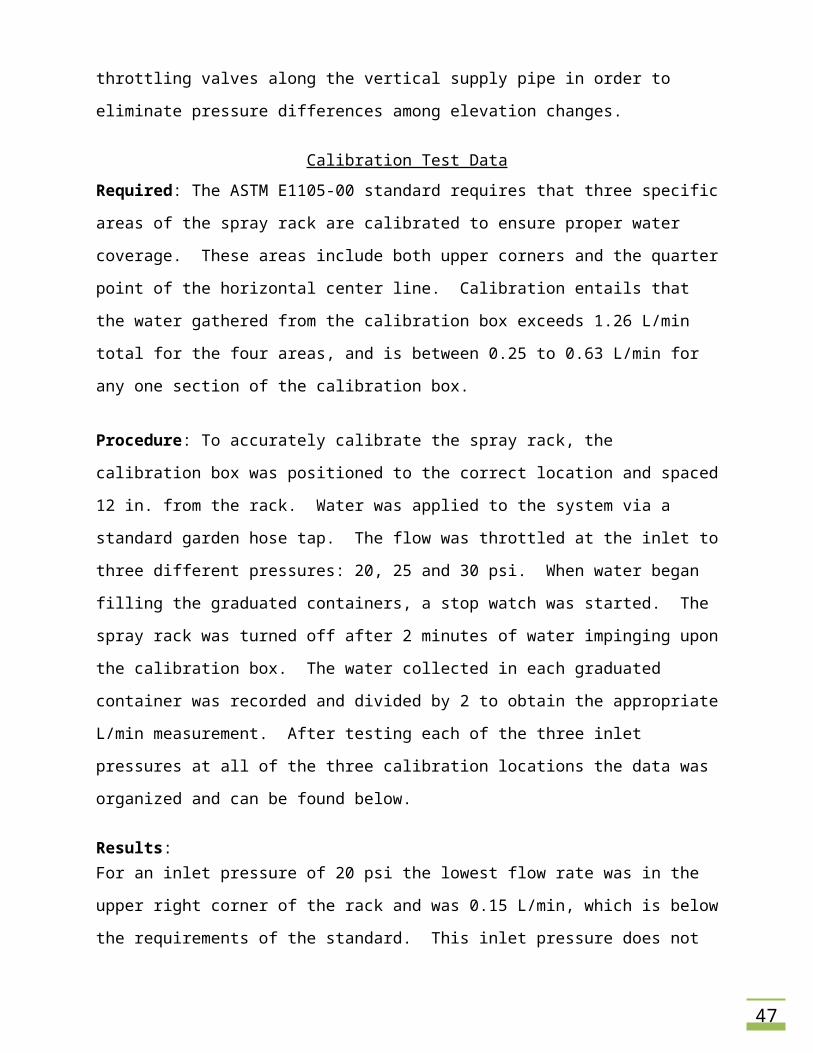
Results: For an inlet pressure of 20 psi the lowest flow rate was in the upper right corner of the rack and
was 0.15 L/min, which is below the requirements of the standard. This inlet pressure does not
meet the minimum flow rate of the total four calibration box areas (1.26 L/min) either. The
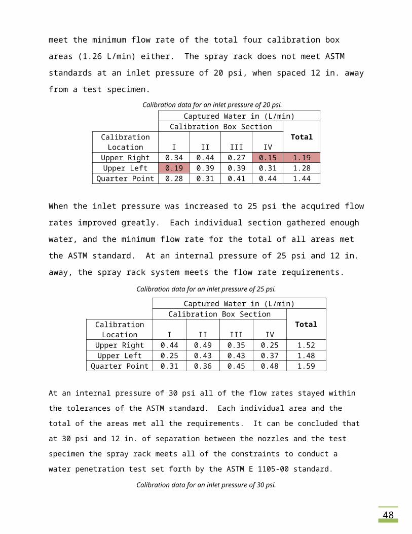
spray rack does not meet ASTM standards at an inlet pressure of 20 psi, when spaced 12 in.
away from a test specimen.
Calibration data for an inlet pressure of 20 psi.
Captured Water in (L/min)Calibration Box Section
TotalCalibration Location I II III IV
Upper Right 0.34 0.44 0.27 0.15 1.19Upper Left 0.19 0.39 0.39 0.31 1.28
Quarter Point 0.28 0.31 0.41 0.44 1.44
35
When the inlet pressure was increased to 25 psi the acquired flow rates improved greatly. Each
individual section gathered enough water, and the minimum flow rate for the total of all areas
met the ASTM standard. At an internal pressure of 25 psi and 12 in. away, the spray rack
system meets the flow rate requirements.
Calibration data for an inlet pressure of 25 psi.
Captured Water in (L/min)Calibration Box Section
TotalCalibration Location I II III IV
Upper Right 0.44 0.49 0.35 0.25 1.52Upper Left 0.25 0.43 0.43 0.37 1.48
Quarter Point 0.31 0.36 0.45 0.48 1.59
At an internal pressure of 30 psi all of the flow rates stayed within the tolerances of the ASTM standard.
Each individual area and the total of the areas met all the requirements. It can be concluded that at 30
psi and 12 in. of separation between the nozzles and the test specimen the spray rack meets all of the
constraints to conduct a water penetration test set forth by the ASTM E 1105-00 standard.
Calibration data for an inlet pressure of 30 psi.
Captured Water in (L/min)Calibration Box Section
TotalCalibration Location I II III IV
Upper Right 0.43 0.50 0.39 0.27 1.58Upper Left 0.26 0.44 0.44 0.40 1.54
Quarter Point 0.32 0.38 0.50 0.50 1.70
36
APPENDIX C: OPERATION MANUALS
Overview
In order to complete a successful water penetration test to conform to ASTM standards, the
spray rack must be calibrated. At a test site, the rack must be assembled and set up at the
same settings used to calibrate the rack. The following instructions describe the necessary
procedures to assemble and calibrate the spray rack in order to complete a successful water
penetration test.
Spray Rack Assembly and Testing
Take all of the parts of the spray rack and lay them on the ground.
Set the three horizontal spray pipes in the general area that they will be connected to
the vertical supply pipe (i.e. set them 2.25 ft. apart vertically).
With the nozzles facing the ground, connect the quick release copper couplings of the
vertical pipe to the horizontal pipe inlets.
Maintain the form of the spray rack by placing it gently with the nozzles on the ground.
Fasten the aluminum vertical supports toward the outside of the rack configuration,
making sure that the top of the vertical supports (labeled in red) are located at the top
of the rack.
Install the water supply (garden hose) to the inlet of the rack, making sure that the con-
nection is tight to eliminate pressure losses due to leaks.
Remove the rack from the ground and set it upright, resting on the bottom of the verti-
cal supports.
Align the window spacers in their respective locations: two on the top horizontal pipe,
and one ¾ down the vertical pipe. Set the telescoping tubing at the required distance to
achieve 12 inches of space between the nozzles and the test specimen.
For specimens that are above the first floor of the building use ropes to suspend the rack
to the correct elevation.
For specimens on the first floor of the building, acquire the spray rack stand. Determine
the necessary height elevation needed, and set the stand at that height. Connect the
37
carabiners of the stand to the hanging mounts and raise the rack to the appropriate
height.
When the spray rack is located in the correct location, adjust the inlet throttling valve
until the pressure gauge on the rack reads the necessary pressure determined during
calibration to meet the required flow rates, begin the test.
Calibration of the Spray Rack System
With the spray rack assembled via the instructions above, use the spray rack stand to
hold the rack in place at ground level.
Position the calibration box vertically along the calibration stand by loosening the hose
clamps and sliding to the appropriate location. Follow this procedure for the graduate
container rack so that it is fastened just below the calibration box.
Place each of the calibration box hoses into the individual graduated containers by using
the Velcro tape.
Move the calibration stand and assembly to the calibration locations outline in the ASTM
standard.
Open the inlet throttling valve and allow water to impinge upon the calibration box.
When water begins filling the graduated containers begin timing the process.
After adequate water has been gathered in each container stop the timer, and turn off
the rack. Let the water drain from the box sections before making measurements.
Record the amount of water collected in each container and divide it by the time it took
to fill them, this method will result in obtaining a L/min measurement for each section of
the calibration box.
Validate that the flow rates from each section, and the total of all sections of the calibra-
tion box, fall within the required flow rates as outline in the ASTM standard.
Record the inlet pressure that the measurements were made, this is the pressure that
must be used when a water penetration test is carried out on a job site.
APPENDIX D: PRODUCT DATA SPECIFICATIONS TABLE
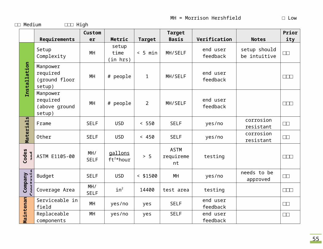
MH = Morrison Hershfield □ Low □□ Medium □□□ High
MH = Morrison Hershfield □ Low □□ Medium □□□ HighRequirements Customer Metric Target Target Basis Verification Notes Priority
Inst
alla
tion
Setup Complexity MH setup time (in hrs) < 5 min MH/SELF end user feedback setup should be
intuitive □□
Manpower required (ground floor setup) MH # people 1 MH/SELF end user feedback □□□
Manpower required (above ground setup)
MH # people 2 MH/SELF end user feedback □□□
Mat
eria
ls Frame SELF USD < 550 SELF yes/no corrosion resistant □□
Other SELF USD < 450 SELF yes/no corrosion resistant □□
Code
s and
St
anda
rds
ASTM E1105-00 MH/SELF gallonsft2*hour > 5 ASTM
requirement testing □□□
Com
pany
Co
nstr
aint
s
Budget SELF USD < $1500 MH yes/no needs to be approved □□
Coverage Area MH/SELF in2 14400 test area testing □□□
Mai
nten
a Serviceable in field MH yes/no yes SELF end user feedback □□Replaceable components
MH yes/no yes SELF end user feedback □□
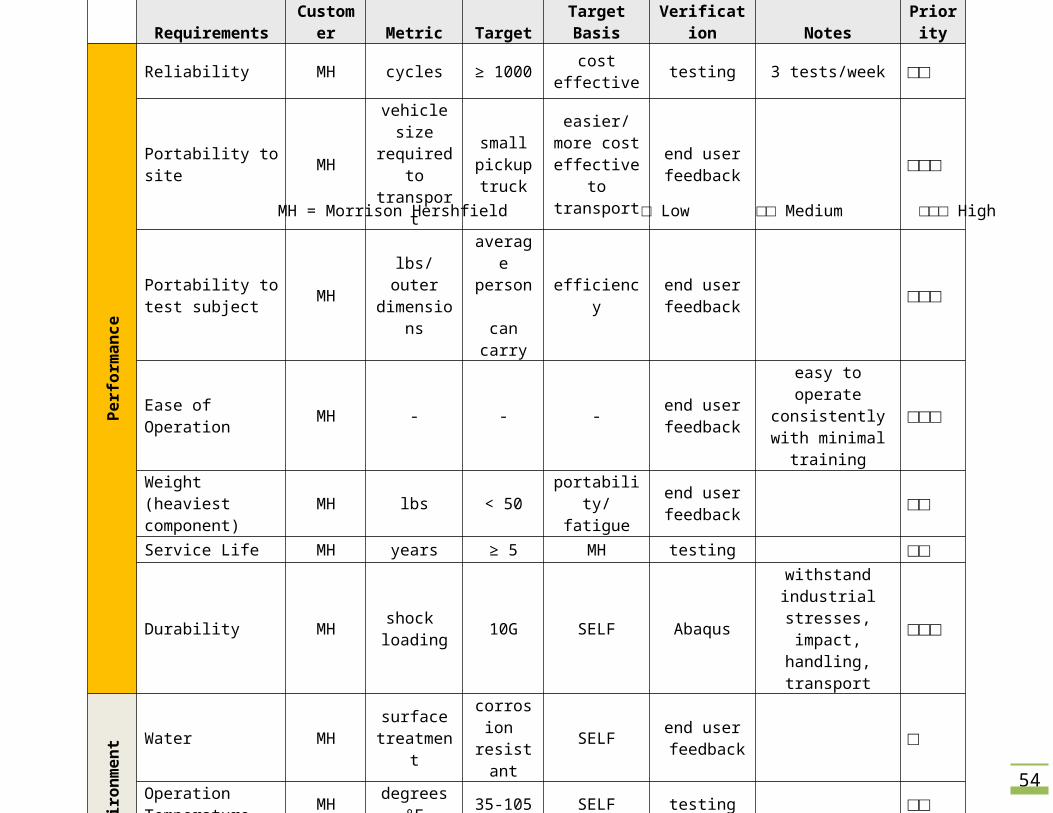
Requirements Customer Metric Target Target Basis Verification Notes PriorityPe
rfor
man
ce
Reliability MH cycles ≥ 1000 cost effective testing 3 tests/week □□
Portability to site MHvehicle size required to transport
small pickup truck
easier/more cost effective to transport
end user feedback □□□
Portability to test subject MH lbs/outer
dimensions
average person
can carryefficiency end user
feedback □□□
Ease of Operation MH - - - end user feedback
easy to operate consistently with minimal training
□□□
Weight (heaviest component) MH lbs < 50 portability/
fatigueend user feedback □□
Service Life MH years ≥ 5 MH testing □□
Durability MH shock loading 10G SELF Abaqus
withstand industrial stresses, impact,
handling, transport□□□
Envi
ronm
ent Water MH surface
treatmentcorrosion resistant SELF end user
feedback □
Operation Temperature MH degrees °F 35-105 SELF testing □□
Suspension forces SELF factor of safety 10G consistent
operationend userfeedback □□
Safe
ty Frame Integrity MH factor of safety 10G SELF Abaqus □□□
Handling MH - - - - □□□
39
nce Repair complexity MH/SELF difficulty easy SELF end user feedback □□
Docu
men
tatio
n PDS self deadline 2/8/2010 PSU documentation □□
Progress Report self deadline 3/8/2010 PSU documentation □□
Final Report self deadline 5/31/2010 PSU documentation □□□
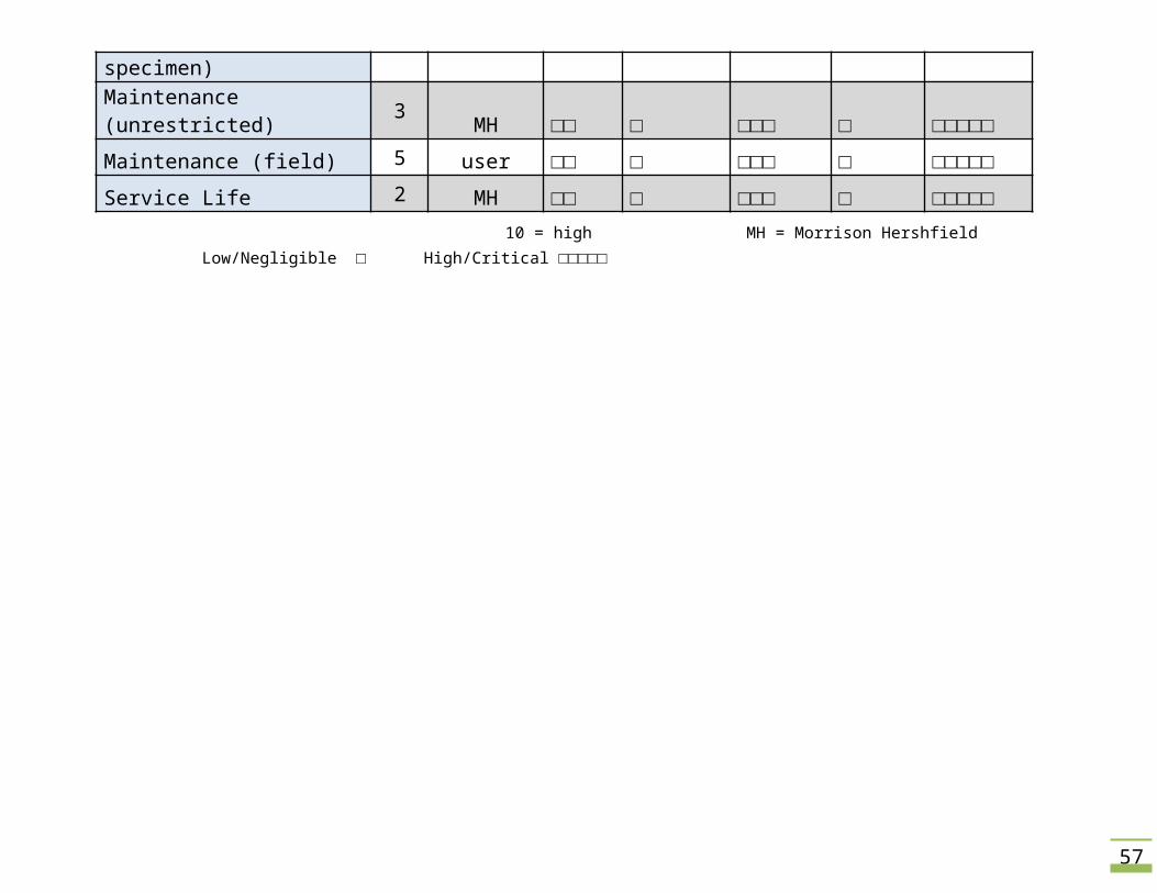
Timeline self deadline PSU documentation □□APPENDIX E: HOUSE OF QUALITY TABLE
Criteria Engineering
Customer Requirements
Impo
rtan
ce
Cust
omer
Cost
Wei
ght
Desig
n
Out
er
Dim
ensio
ns
Com
pone
nts
Performance 10 MH/user □□□ □ □□□□□ □ □□□Ease of Installation 6 user □□ □□□ □□□□ □ □□Ease of Operation 6 user □ □ □□□□□ □ □□□Portability (to site) 7 MH/user □ □ □□□□□ □□□□□ □□□Manpower Required 9 MH/user □ □□□□□ □□□□□ □ □Portability (to specimen) 9 MH/user □ □□□□□ □□□□ □□□□□ □□
Maintenance (unrestricted) 3 MH □□ □ □□□ □ □□□□□
40
Maintenance (field) 5 user □□ □ □□□ □ □□□□□
Service Life 2 MH □□ □ □□□ □ □□□□□ 10 = high MH = Morrison Hershfield Low/Negligible □ High/Critical □□□□□
APPENDIX F: PART DRAWINGS
42
43
44
45
46
47
48

49
50
APPENDIX G: BILL OF MATERIALS
HD = Home Depot MS = Metal Supermarkets AH = Ace Hardware
DATE
Appl
icati
on
PART
PRIC
E
#
TOTA
L
VEN
DOR
PURC
HASE
R
TOTA
L PU
RCHA
SE
3/7/2010 Test app 3/4 x 10 pvc $0.98 3 $2.94 HD Andy
$30.97
3/7/2010 Test app Dauber $1.31 2 $2.62 HD Andy3/7/2010 Test app primer $4.58 1 $4.58 HD Andy3/7/2010 Test app cement pvc $3.76 1 $3.76 HD Andy3/7/2010 Test app 3/4 cap pvc $0.35 6 $2.10 HD Andy3/7/2010 Test app 3/4 elbow pvc $0.69 1 $0.69 HD Andy3/7/2010 Test app 3/4 cross pvc $1.70 2 $3.40 HD Andy3/7/2010 Test app 3/4 tee pvc $0.33 2 $0.66 HD Andy3/7/2010 Test app 3/4 m adapter $0.33 1 $0.33 HD Andy3/7/2010 Test app sprink HD $9.89 1 $9.89 HD Andy
3/10/2010 Test app 3/4x10 pvc $0.98 1 $0.98 HD Andy
$6.19
3/10/2010 Test app 3/4 f adapt pvc $0.44 1 $0.44 HD Andy3/10/2010 Test app 1/2 elbow pvc $0.90 1 $0.90 HD Andy3/10/2010 Test app 1/2 elbow (type 2) pvc $0.69 1 $0.69 HD Andy3/10/2010 Test app 3/4 busing pvc $0.38 2 $0.76 HD Andy3/10/2010 Test app 3/4 'M' adapter pvc $0.33 1 $0.33 HD Andy3/10/2010 Test app 1/2x260 teflon tape $0.98 1 $0.98 HD Andy3/10/2010 Test app 1/2x24 pvc $0.79 1 $0.79 HD Andy3/10/2010 Test app 1/2 M adapter $0.32 1 $0.32 HD Andy4/1/2010 Test app 3/4 cap pvc $0.35 3 $1.05 HD Andy
$3.08 4/1/2010 Test app 3/4 tee sss $0.33 1 $0.33 HD Andy4/1/2010 Test app 3/4 cross pvc $1.70 1 $1.70 HD Andy5/8/2010 Rain rack Pipe Bushing 3/4-1/2" $2.37 12 $28.44 HD Andy $28.44
5/10/2010 Rain Rack Copper Tube 3/4" $15.53
3 $46.59 HD Andrew $264.93
51
5/10/2010 Rain Rack Copper Fem Adpt $5.81 12 $69.72 HD Andrew5/10/2010 Rain Rack 3/4 Copper Tee $2.39 18 $43.02 HD Andrew5/10/2010 Rain Rack 3/4 Copper Cap $1.11 6 $6.66 HD Andrew5/10/2010 Rain Rack 8oz flux $6.43 1 $6.43 HD Andrew5/10/2010 Rain Rack Copper Female adpt $3.54 1 $3.54 HD Andrew
5/10/2010 Rain Rack Pipe Cutter$10.2
6 1 $10.26 HD Andrew5/10/2010 Rain Rack 3/4" valve $9.87 3 $29.61 HD Andrew5/10/2010 Rain Rack Shark Bit Clip $1.54 2 $3.08 HD Andrew5/10/2010 Rain Rack Shark Bite joint $6.92 3 $20.76 HD Andrew
5/10/2010 Rain Rack 1/2 lb solder$13.8
1 1 $13.81 HD Andrew5/10/2010 Rain Rack Interior brush $1.95 1 $1.95 HD Andrew5/10/2010 Rain Rack Exterior Brush $3.46 1 $3.46 HD Andrew5/10/2010 Rain Rack Copper male Adapter $2.11 1 $2.11 HD Andrew5/10/2010 Rain Rack 3/4 Copper elbow $1.31 3 $3.93 HD Andrew5/10/2010 Misc Arch Aluminum Tube (6063) square 1x1x12, 1/16" $2.37 1 $2.37 McMaster Andy
$28.21
5/10/2010 Misc Arch Aluminum Tube (6063) square (3/4)x(3/4)x12, 1/8" $2.56 1 $2.56 McMaster Andy5/10/2010 Misc Arch Aluminum Tube (6063) square (3/4)x(3/4)x36, 1/8" $6.23 1 $6.23 McMaster Andy5/10/2010 Misc Arch Aluminum Tube (6063) square 1x1x3', 1/16" $5.29 1 $5.29 McMaster Andy5/10/2010 Misc Release pin W/lanyard, 3/16", 1.3" Usable length $3.92 3 $11.76 McMaster Andy
5/10/2010 Misc Brass Spray Nozzle, 3/8" NPT Male, 2gpm@40psi, 120 deg $10.19 12 $122.2
8 McMaster Andy
5/12/2010 Rain rack Butane $5.99 1 $5.99 4th Store Andy $5.99
5/17/2010 Calibration Box Aluminum Sheet (6061) 3x4' $68.3
6 1 $68.36 MS Andrew$258.49
5/17/2010 Misc. Aluminum Plate (6061) 1x2' $44.8
6 1 $44.86 MS Andrew
5/17/2010 Calibration Box Aluminum Square Tube (6061) 1.5x1.5x72$26.3
6 2 $52.72 MS Andrew5/17/2010 Misc Aluminum flat (6061) .1875x.75x72 $4.00 4 $15.98 MS Andrew
5/17/2010 Rain Rack Aluminum Tube Round (6061) .75x48, 0.049"$13.7
8 1 $13.78 MS Andrew5/17/2010 Rain Rack Aluminum Tube Round (6061) .625x48, 0.058 $19.2
9 1 $19.29 MS Andrew
52
5/17/2010 Misc. Aluminum Plate (6061) 1x1', 0.5" $43.5
0 1 $43.50 MS Andrew5/18/2010 Calibration Box 1/4 Barb $1.48 1 $1.48 HD Andrew $20.94
This box tabulated on previous page
5/18/2010 Calibration Box 3/4 cop cplg $0.87 2 $1.74 HD Andrew5/18/2010 Calibration Box Microtube $4.07 1 $4.07 HD Andrew5/18/2010 Rain Rack 15" velcro $3.96 1 $3.96 HD Andrew5/18/2010 Rain Rack 23' velcro $3.46 1 $3.46 HD Andrew5/18/2010 Calibration Box swivel $4.12 1 $4.12 HD Andrew5/18/2010 Calibration Box cop male adp $2.11 1 $2.11 HD Andrew5/19/2010 Calibration Box Graduated Pitcher $8.75 4 $35.00 Scientific Andrew $35.00 5/21/2010 Rain Rack Brass Nozzle, 1/8" NPT Male, 0.5 GPM @40 PSI, 120Deg $7.52 12 $90.24 McMaster Andy
$106.24 5/21/2010 Rain Rack Brass Hex Reducing Bushing 3/8" Male X 1/8" Fem $1.00 16 $16.00 McMaster Andy5/21/2010 Rain Rack Brass Nozzle, 1/4" NPT Male, 1 GPM @40PSI, 120Deg $8.02 12 $96.24 McMaster Andy5/21/2010 Rain Rack Brass Nozzle, 1/8" NPT Male, 0.7 GPM @40 PSI, 120Deg $7.52 12 $90.24 McMaster Andy5/21/2010 Rain Rack Brass Hex Reducing Bushing 3/8" Male X 1/4" Fem $1.49 16 $23.84 McMaster Andy
5/24/2010 Calibration Box JB Weld$19.4
7 1 $19.47 AH Luke $19.47
5/25/2010 Rack Stand Aluminum Pipe (6061) 1.25x72"$27.1
7 1 $27.17 MS Andy $64.33
5/25/2010 Rack Stand Aluminum Tube (6061) 1.25"x108", .125" thickness$37.1
6 1 $37.16 MS Andy5/26/2010 Calibration Box Combo Pack $1.41 1 $1.41 HD Andrew
$3.61 5/26/2010 Calibration Box Plastic Baggds $0.98 1 $0.98 HD Andrew5/26/2010 Rain rack 1/4x2" lag screw $0.46 1 $0.46 HD Andrew5/26/2010 Rain rack 1/4x2x1/2" H bolt $0.76 1 $0.76 HD Andrew5/27/2010 Calibration Box Rubber washer (4) 1/4" $0.83 2 $1.66 HD Andy $1.66 5/27/2010 Misc Shipping parts back $9.70 1 $9.70 USPS Andy $9.70 5/27/2010 Rain Rack Leg Tip, black rubber, 1" $0.69 6 $4.14 AH Andy
$117.85
5/27/2010 Rain Rack Aluminum bulk (used for supports) $6.50 6 $39.00 AH Andy5/27/2010 Rack Stand Eye Bolt $7.49 2 $14.98 AH Andy5/27/2010 Rack Stand 16 gauge 11/2 dia squar tubing pl $0.69 3 $2.07 AH Andy5/27/2010 Calibration Box Hose Clamp $4.79 2 $9.58 AH Andy5/27/2010 Rack Stand 2 1/2" snapper $4.19 2 $8.38 AH Andy5/27/2010 Rack Stand Spring Snap link $4.99 2 $9.98 AH Andy

53
5/27/2010 Rack Stand 1x8 glv nipple $3.79 1 $3.79 AH Andy5/27/2010 Rack Stand 1" Galv Tee $4.19 1 $4.19 AH Andy5/27/2010 Rack Stand nuts and washers $1.53 2 $3.06 AH Andy5/27/2010 Rack Stand nuts and washers $2.19 2 $4.38 AH Andy5/27/2010 Rack Stand Large Hex Bolt $7.15 2 $14.30 AH Andy5/30/2010 Calibration Box Stopwatch $7.99 1 $7.99 Fred Meyer Andrew $12.28 5/30/2010 Calibration Box Auto Epoxy $4.29 1 $4.29 Fred Meyer Andrew5/30/2010 Calibration Box Caster wheels $4.49 1 $4.49 HD Andy
15.175/30/2010 Rain rack Water Gage
$10.68 1 $10.68 HD Andy
5/30/2010 Calibration Box blk 5/8" leg tips $1.69 1 $1.69 AH Andy
$49.32
5/30/2010 Calibration Box Tip Leg vynl blk 1/2" $1.49 1 $1.49 AH Andy5/30/2010 Calibration Box Round pad 1.5" $3.29 1 $3.29 AH Andy5/30/2010 Rain rack 16 gage 11/4 dia squar tubing $0.99 4 $3.96 AH Andy5/30/2010 Rain rack Wet/dry 9x11 150 grit sandpaper $0.99 3 $2.97 AH Andy5/30/2010 Rain rack Standard 9x11 150 grit sandpaper $1.69 2 $3.38 AH Andy5/30/2010 Rain rack Spray paint gray primer $6.99 2 $13.98 AH Andy5/30/2010 Rain rack Spray paint olive $4.79 2 $9.58 AH Andy5/30/2010 Rain rack Spray paint smoke gray $4.49 2 $8.98 AH Andy
6/1/2010 School Capstone Poster$65.2
5 1 $65.25 Kinko's Andy $65.25
6/1/2010 Calibration Box Scrap glass (acrylic) $4.00 1 $4.00 AH Andy
$26.41 6/1/2010 Rain Rack Metric Fasteners $0.38 6 $2.28 AH Andy6/1/2010 Calibration Box 11 gage 11/2 dia square tubing plug $0.79 4 $3.16 AH Andy6/1/2010 Calibration Box Velcro strip 18" black $3.99 1 $3.99 AH Andy6/1/2010 Rain Rack Lacquer Gloss $6.49 2 $12.98 AH Andy
Grand Total $1173.53
Purchaser
Andrew$595.2
5
Andy$558.8
1 Luke $19.47
Returned for credit, not included in price
54
APPENDIX H: ASTM E1105-00 STANDARDS

56
57
58
59