Embed Size (px)
Citation preview

Tender document
European open procedure
Smart@Fire
Deadline for receipt of the offers: [date and time]
Date: [date]
Reference: [reference]

SummaryThis tender document concerns the purchasing of Personal Protective Systems (PPS).
In this tender procedure [number] contracting authorities are participating from [number] countries.
The priority challenge for tenderers covers primarily the development of a PPS (including - but not limited to - standard turnout gear with integrated ICT systems covering environmental sensing, communication, localization, visualization, interfaces for third party add-ons, Incident Coordinating Officer platform, data storage for a posteriori analysis and training)
[Name of the leading contracting authority] manages this tender procedure, acting on its own behalf and the behalf of the following participating contracting authorities:
(i) ….(ii) ….(iii) ….
OR
[Name of the leading contracting authority] acts for the following participating contracting authorities as ‘central purchasing body’ (article 2 and 37 Directive):
(i) ….(ii) ….(iii)
[Explanation: see chapter 1]
History
As a preparation for this tender procedure a pre-commercial procurement (PCP, which concerns the research and development phase before commercialization) has been used with the following phases:
Phase 1: Tendering Stage/Solution Design: has successfully been demonstrated by the invited tenderers by submitting a feasibility study (completed).
o Published on 6 June 2014 in Tender Bulletin. o Published online on 21 June 2014.
Bid submission and admission based on participation requirements and administrative documents and technical and financial offer.
Phase 2: Execution Stage, Prototyping and Testing: the participants of the PCP had the opportunity to develop prototypes or demonstrators, that has been evaluated by the Evaluation Committee (completed).• Phase I (solution design): tender document published on 6 June 2014 in the
bulletin of tenders and published on 21 June 2014 in the Official Journal of the European Union (OJEU).
• Phase II (prototype development): sent to the participants on 18 May 2015.• Phase III (Pre-commercial small scale product/service development): sent
to the participants on 4 April 2016.
bb

Phase 3: First Batch Production and Testing: has been intended for the original development and testing of a limited volume of first products/services (test series) (completed).In each phase, tenderers were competing with each other for assignments.
The “European Tender Procedure Stage”: the commercialization phase in which commercial roll-out of the PPS will take place: submission and admission of tenders, based on participation requirements and administrative documents. A technical and financial offer is intended to make a decision for the final producer of the PPS.This can be another legal entity then the tenderers in the PCP.
This tender procedure is open to every supplier, regardless of the fact a supplier participated in the Innovation Platform or in the pre-commercial procurement (PCP).Documents of the phases before the European tender procedure are attached to this tender document as background information:
The Framework Agreement;
The Challenge Brief (includes Functional Requirements);
The Invitation to Tender for Phase 1;
The Invitation to Tender for Phase 2.
Tender documentsThis tender document for the European open procurement procedure is a separate document. In case of conflict between the following documents with regard to the same matter, the order of priority and prevalence between the documents shall be as follows:
questions and answers document;
the tender document;
the framework agreement;
the work orders;
other tender documents, if any; and
the tender of the contractor.
bb

Index1 Glossary.......................................................................................................................72 Contracting Authority, Participating Contracting Authorities, one single contract, lots
and goal tender procedure...........................................................................................92.1 Contracting Authority................................................................................................92.2 Participating Contracting Authorities........................................................................92.3 Scope of the tender- Smart@Fire..............................................................................92.4 One single contract.................................................................................................102.5 Lots.........................................................................................................................102.6 Goal tender procedure............................................................................................10
3 Tender procedure.......................................................................................................113.1 European open procedure.......................................................................................113.2 Contact...................................................................................................................113.3 Indicative time schedule.........................................................................................123.4 Tender submission guidelines.................................................................................123.5 Content of the tender..............................................................................................133.6 Questions & Answers document..............................................................................133.7 Costs tender............................................................................................................143.8 Variants...................................................................................................................143.9 Conditions...............................................................................................................143.10Applicable law – Competent court –Remedies.........................................................143.11Standstill period......................................................................................................143.12Language................................................................................................................153.13Validity period.........................................................................................................153.14False statements.....................................................................................................153.15Inconsistencies, in accuracies, mistakes etc...........................................................153.16Confidentiality, publicity and information about the award.....................................153.17Framework agreement............................................................................................163.18Disclaimer...............................................................................................................163.19Withdrawal of the tender procedure.......................................................................163.20Complaints..............................................................................................................173.21Measures environmental, social and labor law........................................................17
4 Partnerships...............................................................................................................184.1 Consortium..............................................................................................................184.2 Subcontractors........................................................................................................184.3 Reliance on the capacity of other entities...............................................................19
5 Exclusion grounds......................................................................................................205.1 Mandatory exclusion grounds.................................................................................20

5.2 Facultative exclusion grounds.................................................................................205.3 Means of proof exclusion grounds...........................................................................21
6 Selection criteria........................................................................................................236.1 Liability insurance...................................................................................................236.2 Annual turnover......................................................................................................236.3 Experience..............................................................................................................246.4 Trade register.........................................................................................................25
7 Minimum requirements..............................................................................................268 Award criteria.............................................................................................................27
8.1 The most economically advantageous tender/the best price-quality ratio..............278.2 Assessment award criteria......................................................................................298.3 Pricing sheet...........................................................................................................30
1 Appendix 1: List of documents...................................................................................312 Appendix 2: Tender Query Form................................................................................323 Appendix 3: Framework agreement...........................................................................334 Appendix 4: General Conditions.................................................................................345 Appendix 5: Statement of Consortium......................................................................356 Appendix 6: Statement of Subcontracting.................................................................367 Appendix 7: Statement Other Entity.........................................................................378 Appendix 8: Uniform Single Procurement Document (ESPD).....................................389 Appendix 9: Reference Form.....................................................................................3910 Appendix 10: List of Minimum Requirements.............................................................40Contents.............................................................................................................................42Definitions..........................................................................................................................420. Context of Smart@Fire and the preparation of the Challenge Brief Template...........43
0.1. The Smart@Fire Pre-Commercial Procurement (PCP) process.................................430.1.1. Positioning of the PCP tender.................................................................430.1.2. Pre-commercial Procurement in phases.................................................440.1.3. Preliminary Stage: Needs Assessment – Priority User needs..................460.1.4. Preliminary Stage: The State-of-the-Art..................................................471.1.2. Main challenges to be tackled in the scope of Smart@Fire beyond the state-of-the-art.....................................................................................................491.1.3. First Stage: The market consultation - Innovation Platform....................501.1.4. Second Stage: The Pre-Commercial Procurement..................................52
1. Scope of the Tender.................................................................................................521.1. General objective of the tender: Purchase of [#] PPS systems...............................521.2. PPS tender scope....................................................................................................531.3. PPS design constraints............................................................................................57
2. Appendix 1: Functional Requirements........................................................................59
2.1. Chapter structure....................................................................................................592.2. Priority use-cases in the scope of the Tender..........................................................592.3. High-level functional requirements for the PPS in scope of the Tender...................602.4. Functional architecture of the PPS in scope of the Tender......................................64
1.1.5. Actors.....................................................................................................661.1.6. Functional building blocks enable key use-cases....................................671.1.7. Functional Requirements of the functional building blocks.....................69
11 Appendix 11: Award criteria (detailed description)...................................................8712 Appendix 12: Scoring model......................................................................................9213 Appendix 13 Tender Form (Technical and Financial offer).........................................96_Toc473630120

1 Glossary
The terms used in this tender document, written in capital, have the following meaning:
[Explanation: in this tender procedure contracting authorities from different member states act jointly in the award of the framework agreement for a Personal Protective System. Contracting authorities from different member states may act jointly in concluding a framework agreement by using one of the following means (article 39 Directive 2014/24):
(i) The provision of centralized purchasing activities by a central purchasing body located in another member state. The national provisions of the member state where the central purchasing body is located is applicable to the tender procedure.
(ii) Several contracting authorities from different member states may jointly conclude a framework agreement. The participating contracting authorities shall conclude an agreement that determines:a. the responsibilities of the parties and the relevant applicable national provisions; b. the internal organization of the tender procedure, including the management of
the procedure, the distribution of the supplies to be procured and the conclusion of contracts.
A participating contracting authority fulfills its obligations pursuant to Directive 2014/24 when it purchases supplies from a contracting authority which is responsible for the tender procedure. The allocation of responsibilities and the applicable national law shall be referred to in the tender documents for jointly awarded public contracts.
(iii). Set up a joint entity. The participating contracting authorities shall, by a decision of the competent body of the joint entity, agree on the applicable national procurement rules of one of the following member states:a. the national provisions of the member state where the joint entity has its
registered office. b. the national provisions of the member state where the joint entity is carrying out
its activities.]
Contracting Authority
[Name of the leading contracting authority] acts for the Participating Contracting Authorities as ‘central purchasing body’ (article 2 and 37 Directive).
OR
[Name of the leading contracting authority] and the Participating Contracting Authorities have agreed to perform the conclusion of the framework agreement for a PPS jointly. The Contracting Authority manages this tender procedure acting on its own behalf and the behalf of the Participating Contracting Authorities.
Participating Contracting Authorities

The Contracting Authority manages this tender procedure acting on its own behalf and the behalf of the following Participating Contracting Authorities:
(i) [name Participating Contracting Authority](ii) [name Participating Contracting Authority](iii) [name Participating Contracting Authority](iv) [etc.]
[ Name ] Act
[Name of the act, which is applicable to this tender procedure and in which Directive 2014/24/EU is implemented in the applicable national law of this tender procedure.]
Directive
Directive 2014/24/EU of the European Parliament and of the Council of 26 February 2014 on public procurement and repealing Directive 2004/18/EC.
ESPD
The European Single Procurement Document, Commission implementing Regulation (EU) 2016/7 of 5 January 2016 establishing the standard form for the European Single Procurement Document. The ESPD is available in all EU languages on the website of the European Commission (see: ec.europa.eu) (appendix 8).
General conditions
[Description of the chosen general conditions which are applicable to the framework agreement] (appendix 4).
PCP
Pre-commercial procurement is a procurement method based on an open competition which enables contracting authorities to engage with innovative businesses and other interested organisations in research and development (R&D) projects, to arrive at innovative solutions that address specific public sector challenges and needs for which there is no solution on the market as yet. The new innovative solutions are developed through a phased procurement of development contracts to reduce risk. For more information please read also the “Invitation to tender” from phase 1, first capital.
A PCP that is seeking to award contracts for R&D services falls outside the scope of the EU procurement directives (article 14 Directive).
PPS
The Personal Protective System, which is described in section 2 of this tender document.
[add more definitions]

2 Contracting Authority, Participating Contracting Authorities, one single contract, lots and goal tender procedure
2.1 Contracting Authority The Contracting Authority acts for the Participating Contracting Authorities as ‘central purchasing body’ (article 2 and 37 Directive).
OR
The Contracting Authority and the Participating Contracting Authorities have agreed to perform the conclusion of the framework agreement for a PPS jointly. The Contracting Authority manages this tender procedure acting on its own behalf and the behalf of the Participating Contracting Authorities.
[Description of the Contracting Authority]
2.2 Participating Contracting Authorities The Contracting Authority manages this tender procedure acting on its own behalf and the behalf of the following Participating Contracting Authorities:
(i) [name Participating Contracting Authority](ii) [name Participating Contracting Authority](iii) [name Participating Contracting Authority](iv) [etc.]
[Description of the Participating Contracting Authorities]
2.3 Scope of the tender 2.1 The subject-matter of the contract is the procurement of a “PPS central nerve
system: system architecture, communication, localization & interfaces”. This PPS covers multiple elements listed hereafter.
The PPS central nerve system architecture: Communication network with sufficient indoor penetration and update rate
towards the intervention coordinating officer compliant to mission critical environment.
Balanced trade-offs between distributed and central processing, scalability of system, local performance vs. remote responsiveness (online vs. offline operation), interfaces, etc.
Limited integration with textile (underwear, turnout gear, or…): Cabled and/or wireless. When cabled: easy mounting/replacing of
cables/connectors; durability of cables/connectors; dealing with different turnout gear sizes; integrating UIs. When wireless: limiting interference; easy start-up and self-assessment of correct operations via minimal # UI’s.

Electromagnetic shielding of the different devices (sensors, processing unit,…), without implementing military-grade measures.
Localization engine: A localization system (preferentially GPS with inertial subsystem) with
limited indoor drift (reference <1% of inertial track distance). A relative track & trace map, enabling ‘meet point’ and ‘recovery path’
instructions. Available Cartesian coordinated maps (e.g. Google maps) used as overlay.
Beacon-based solution instead of inertial at increased risk, principally fast & accurate deployment and TCO.
Intuitive user feedback (restitution, visualization): For the intervention coordinating officer: intuitive UI dashboard, conform
way of working. For the firefighter: Full usability satisfaction for at least 90% of the users.
Coupling via defined application interfaces (e.g. Bluetooth application profile) with
(Standalone) environmental temperature measurement device Optional, when available: (standalone), cheap, simple and robust
explosive gas detector (e.g. indicating the presence of explosive gasses without measuring ppm details).
2.4 One single contractThe Contracting Authority has the opinion that the contract for the development of a PPS concerns one single public contract. The different parts of this contract fulfill one economic and technical function. The Contracting Authority has therefore not combined unnecessarily multiple contracts into one contract.
[Explanation: if required in the applicable national law: add motivation.]
2.5 LotsThe Contracting Authority has not subdivided the contract into lots.
[Explanation: if required in the applicable national law: add motivation.]
2.6 Goal tender procedureThe purpose of this tender procedure is to conclude a framework agreement with one single supplier. The framework agreement will be concluded for an initial period of [number] years. The Contracting Authority is allowed to extend the framework agreement with [number] times [number] years (appendix 3).
[3] [6] months before the expiry of the framework agreement the Contracting Authority will inform the supplier by written notice whether or not the framework agreement will be extended.

3 Tender procedure
3.1 European open procedureThe Contracting Authority applies the European open procedure.
With this tender document, the Contracting Authority is making a call for competition. Any interested supplier may submit a tender in response of this call for competition.
This tender procedure is open to every supplier, regardless of the fact a supplier participated in the Innovation Platform or in the pre-commercial procurement.
The [name of the act, which is applicable to this tender procedure and in which Directive 2014/24/EU is implemented in the applicable national law of this tender procedure] is applicable to this tender procedure.
[Explanation: if required in the applicable national law: add motivation.]
3.2 ContactAll communication with respect to the tender procedure must only be made by e-mail through the following contact person of the Contracting Authority. In the case of absence of this contact person all communication must be made by e-mail through the deputy of the contact person.
Correspondence with the Contracting Authority must always include the name of the tender procedure.
Contact details
Name contact person [=]
E-mailadres [=]
Adres [=]
Postal adres [=]
Name deputy contact person [=]
E-mailadres [=]
Adres [=]
Postal adres [=]
3.3 Indicative time scheduleThe Contracting Authority aims the following time schedule:
Date Activity
….. Publication contract notice and tender document available
….. Deadline for receipt questions
….. Deadline for answering questions
…… Deadline for tenders
…… Assessment by evaluation committee
…… Notification provisional award decision
…… Notification final award decision
…. Framework agreement to be signed
…… Expected ordering
The Contracting Authority reserves the right to adjust the time schedule if necessary. This will be communicated in a timely manner to all tenderers.
3.4 Tender submission guidelinesDeadline for the receipt of the tenders is: [date] [time] (CET). Tenders received after this date and time will be excluded from participation in the tender procedure.
Tenderers willing to submit a tender shall submit an envelope containing the documents as listed in appendix 1,which must be delivered at the following address of the Contracting Authority: [address]
Additionally an electronic format (in Word or equivalent) will have to be sent to [e-mail] not later than [date] [time] (CET).
The envelopes received after the deadline will not under any circumstances be admitted to the tender procedure even if shipped before the expiry of the term. This also applies to envelopes sent by registered mail with notification of reception: the shipping date resulting from the stamp will not be taken into account; these envelopes will not be opened and will be considered as undelivered.

By the submission of the tender, the tenderer marks its unreserved acceptance to all terms and conditions contained in the tender documents and previously produced documents. The tender may not, under penalty of exclusion, contain any reservation in relation to any conditions of any of the tender documents.
OR
Deadline for the receipt of the tenders is: [date] [time] (CET). Tenders received after this date and time will be excluded from participation in the tender procedure.
Tenderers willing to submit a tender shall submit the tender, containing the documents as listed in appendix 1, through the online tendering system [name online tendering system].
By the submission of the tender, the tenderer marks its unreserved acceptance to all terms and conditions contained in the tender documents and previously produced documents. The tender may not, under penalty of exclusion, contain any reservation in relation to any conditions of any of the tender documents.
[Explanation: if the applicable national law requires tenderers to submit the tender through an online tender system, add necessary provisions of the applicable online tendering system.]
3.5 Content of the tenderThe content of the tender should include all documents listed in the ‘List of Documents’ (appendix 1), of which is indicated that these documents are to be submitted by tenderers (consortiums) at the closing date of the tender.
All documents submitted by the tenderer should contain the name of the tenderer.
The content of the appendixes, declarations and forms shall not be amended by the tenderer.
The Contracting Authority could exclude incomplete tenders from participation from the tender procedure.
The Contracting Authority will not return any received tender.
3.6 Questions & Answers documentTenderers may ask questions about the tender documents. Questions or requests for clarification concerning the tender documents must have been received no later than [date] [time] (CET). These questions must be addressed to [e-mail] and submitted on the form supplied in appendix 2 (Tender Query Form). After this date and time, no additional questions will be allowed nor answered. [Optional: all questions received will be dealt with and answered during an information session on [date] [time] (CET). After the information session, no additional questions will be allowed nor answered.
Optional 2: If using an the online tendering system, you can use online Q&A]
All questions can only be sent by e-mail. It is not possible to ask questions on the phone or personal.
Please quote your reference number when contacting us to help us answer the query.

A summary of questions and answers addressed will be added to the Questions & Answers Document (Q&A). The updated Q&A will also be distributed to all those who have registered for the competition. The identity of the questioner will not be disclosed. The Q&A will be part of the tender documents. In the event of a conflict or inconsistency between the Q&A and the tender document, the Q&A will prevail.A supplier can ask for not distributing information to all suppliers if this would harm commercial interest of the company. In that case the Contracting Authority can decide to give answer directly to the supplier.[Explanation: if required in the applicable national law: add description if it is allowed to end suggestions regarding the framework agreement and general conditions.]
3.7 Costs tenderThe Contracting Authority will not compensate any costs made for the preparation of the tender.ORThe Contracting Authority will compensate the following costs made for the preparation of the tender: [costs]ORThe Contracting Authority will compensate an amount of € [amount] for the preparation of the tender.
3.8 VariantsTenderers are not authorised to submit variants. Tenderers who nevertheless submit a variant will be excluded from the tender procedure.
OR
Tenderers are authorised to submit variants.
[Explanation: if tenderers are authorised to submit variants, the tender documents shall state the minimum requirements to be met by the variants and any specific requirements for their presentation, in particular whether variants may be submitted only where a tender, which is not a variant, has also been submitted. The Contracting Authority shall also ensure that the chosen award criteria can be applied to variants meeting those minimum requirements as well as to conforming tenders which are not variants. It is recommended, however, not to authorise variants.]
3.9 ConditionsThe tender may not contain any condition. Tenderers who nevertheless submit a tender on which conditions apply, will be excluded from the tender procedure.
Terms and (general) conditions of the tenderer are expressly not applicable. A tenderer who has applied its own general terms and (general) conditions shall be excluded from participation in the tender procedure.
3.10 Applicable law – Competent court –Remedies […] law and the applicable laws and regulations in force shall apply to the tender document, the tender procedure and the framework agreement. Amendments of the applicable laws and regulations or decisions of Supervisors of judicial institutions

shall not amend the prices and tariffs offered by the tenderer during the term of the framework agreement. Disputes between the parties involved in this tender procedure must be submitted to the exclusive competent court in […].
3.11 Standstill periodThe Contracting Authority will inform all tenderers of its decision to award the contract.
The Contracting Authority applies a standstill period of [number] calendar days following its notification of the award decision and the date on which the framework agreement will be signed.
Unsuccessful tenderers are allowed to challenge the award decision in court before the framework agreement is signed.
[Explanation: this section should be supplemented by provisions of applicable national law]
3.12 Language Tenders, supporting documents and correspondence must be written in English or be provided with an English translation.
Correspondence and/or documents in another language or not provided with an English translation, will be deemed not to have been received by the Contracting Authority.
3.13 Validity periodTenders should remain open for acceptance for at least 180 calendar days from the date on which the tenderer has submitted its tender.
In the case of legal proceedings, the tender should remain open for acceptance for at least 30 calendar days from the date on which the court has made its decision.
3.14 False statementsThe Contracting Authority reserves the right to verify all information supplied by tenderers on correctness.
The Contracting Authority emphasizes that statements of the tenderer which contain inaccuracies or commitments which cannot be met, could qualify as 'false statements' within the meaning of Article […] of the […] Act. This may result in the exclusion of all tender procedures by the Contracting Authority and the Participating Contracting Authorities. The requested information should therefore be provided very carefully.
3.15 Inconsistencies, inaccuracies, mistakes etc. The Contracting Authority has composed the tender documents with the upmost care. The Contracting Authority expects a proactive attitude of the tenderers. If a tenderer notices, nevertheless, any inconsistency, inaccuracy, mistake etc. the tenderer should notify the Contracting Authority through TenderNed no later than [date] (see paragraph 3.6 of this tender document). A tenderer who will not notify the Contracting Authority of any inconsistency, inaccuracy, mistake etc., has forfeited its

rights to institute legal proceedings with respect to the inconsistencies, inaccuracies, mistakes etc.
3.16 Confidentiality, publicity and information about the award
Assessors, employees and advisors of the Contracting Authority, the Participating Contracting Authorities and other persons contracted to aid in the tendering and award process will handle confidential information confidentially. Assessors with a conflict of interest with one or more of the tenderers will not assess the tenders. All assessors will sign a non-disclosure agreement and a conflict of interest form prior to assessing the tenders.Information from the tenderers is confidential. However, the Contracting Authority will distribute and publish the following information about the tenderer who is awarded with the framework agreement: the name of the tenderer; their location; the title of the project; a short summary of the project; and contract value.
Furthermore, the Contracting Authority and the Participating Contracting Authorities will disclose information provided by the tenderer if the Contracting Authority or the Participating Contracting Authorities are required by law to disclose the information, are being legally forced to provide the information and/or the Contracting Authority and the Participating Contracting Authorities have to disclose the information for the award decision or for legal proceedings.
On the other hand, tenderers should not disclose or release details of the tender documents, other than on an "in confidence" basis to those who have a legitimate need to know or whom they need to consult for the purpose of preparing the tender. Tenderers should not release information concerning the tender documents for publication in the press or on radio, television, screen or any other medium.
3.17 Framework agreement The framework agreement will be signed by the Contracting Authority, the Participating Contracting Authorities and the winning supplier (appendix 3).
By submitting a tender, the tenderer accepts to be bound by the undertakings and conditions of the framework agreement [if applicable: and the General Conditions.]
The tender may not contain any reservation in relation to the conditions of the framework agreement [if applicable: and the General Conditions.] Tenders shall be based on the conditions as set out in the framework agreement [if applicable: the General Conditions.] and the other tender documents.
By the submission of a tender, the tenderer marks its unreserved acceptance of all terms and conditions as set forth in the tender documents. The tender may not, under penalty of exclusion, contain any reservation in relation to any conditions of any of the tender documents.

3.18 Disclaimer While the information contained in the tender documents is believed to be correct at the time of issue, the Contracting Authority (including the Participating Contracting Authorities) will not accept any liability for its accuracy, adequacy or completeness, nor will any express or implied warranty be given. This exclusion extends to liability in relation to any statement, opinion or conclusion contained in or any omission from the tender documents and in respect of any other written or oral communication transmitted (or otherwise made available) to any tenderer. If a tenderer enters into a framework agreement with the Contacting Authority and the Participating Contracting Authorities, it must rely on its own enquiries and on the terms and conditions set out in the framework agreement [if applicable: and the General Conditions] (as and when finally executed), subject to the limitations and restrictions specified in it.Neither the issue of the tender documents nor any of the information presented in it, should be regarded as a commitment or representation on the part of the Contracting Authority, the Participating Contracting Authorities (or any other person or entity) to enter into a contractual arrangement.
3.19 Withdrawal of the tender procedureThe Contacting Authority and the Participating Contracting Authorities reserve the right: not to award the contract when it has not received any tender or suitable tender in
relation to the PPS; to stop, cancel, revoke, re-issue the tender procedure or not to award any contract
for objective reasons (e.g. if prices submitted in the tenders exceed allocated budgets or if prices are clearly disproportionate).
The Contracting Authority and the Participating Contracting Authorities assume no obligation whatsoever to compensate or indemnify the tenders or contractors for any expense or loss they may incur in the preparation of their tenders.
3.20 Complaints[Explanation: if required in the applicable national law: add complaint procedure.]
3.21 Measures environmental, social and labor law[Explanation: if required in the applicable national law: add provisions with respect to compliance of suppliers with environmental, social and labour law.]

4 Partnerships
4.1 ConsortiumIf a tender is submitted by a consortium that does not in itself constitute a legal entity, for example as an unincorporated joint venture or an unincorporated body, all consortia members shall sign the tender and, if applicable, the contract, making them jointly and severally liable.In addition, if a tender is submitted by a consortium that does not in itself constitute a legal entity, all consortia members must submit the ESPD at the closing date of the tender. Furthermore, if a tender is submitted by a consortium that does not in itself constitute a legal entity, the consortium must submit at the closing date of the tender the ‘statement of the consortium’ (appendix 5), signed by all consortium members. A tender from consortiums of companies or groups of service providers, suppliers must specify the role, qualification, experience of each member of the group and which part of the contract will be fulfilled by each of the members of the consortium. Furthermore, the reason to form a consortium should be mentioned on the ‘statement of the consortium’. If two or more tenderers submit a joint bid, one must be designated as the leading partner and will be responsible for all the aspects of the framework agreement. If the tenderer is a joint venture or a consortium of two or more entities, all such entities shall be jointly and severally bound to fulfill the terms of the framework

agreement. The person designated by the consortium to act on its behalf for the purposes of the contract shall have the authority to bind the consortium and is the sole interlocutor for all contractual and financial aspects. The composition or the constitution of the joint venture or consortium shall not be altered without the prior consent of the Contacting Authority. Any alteration of the composition of the consortium without the prior consent of the Contacting Authority may result in the termination of the contract.
4.2 SubcontractorsIf the tenderer (consortium) intents to subcontract parts of the contract to subcontractors, the tenderer shall submit for each of the subcontractors the ESPD at the closing date of the tender. The Contracting Authority shall not award the contract to a tenderer (consortium) if the subcontractor(s) it intends to subcontract parts of the contract to is in one of the situations referred to in paragraphs 5.1 and 5.2 of this tender document. The tenderer (consortium) has to replace such subcontractor. If the tenderer (consortium) intents to subcontract parts of the contract to subcontractors, the tenderer shall submit the ‘statement of subcontracting’ (appendix 6) at the closing date of the tender, signed by the tenderer and all subcontractors. The ‘statement of subcontracting’ shall indicate the part of the contract the tenderer intends to subcontract.The tenderer (consortium) is the prime contractor and contact for the Contracting Authority during the tender procedure and the performance of the framework agreement. Tenderer (combination) is fully responsible for compliance with all obligations under the framework agreement.If the tenderer needs to change subcontractors, these new subcontractors will have to prove that they have at least the same competences relevant to the tender as the subcontractors they will replace and that they comply with all the other contractual conditions, rights and obligations that are in the framework agreement: e.g. complying with the place of performance conditions, respecting the same IPR conditions and the binding unit prices. If the tenderer enters into a subcontract, or change of subcontractors during the execution of the contract, the tenderer will notify promptly the Contracting Authority. The service called for cannot be subcontracted to a third party without prior agreement of the Contracting Authority.
4.3 Reliance on the capacity of other entitiesWith regard to criteria relating to economic and financial standing as set out pursuant to paragraph 6.1 (insurance) and 6.2 (turnover) of this tender document, and to criteria relating to technical and professional ability as set out pursuant to paragraph 6.3 (experience) and 6.4 (trade register) of this tender document, a tenderer (consortium) may rely on the capacities of other entities, regardless of the legal nature of the links which it has with them. If a tenderer (consortium) relies on the capacities of other entities, the tenderer (consortium) shall at the time of submission of the tender submit an ESPD for each other entity the capacities of which it relies on. The Contracting Authority shall verify whether there are grounds for exclusion pursuant to chapter 5 of this tender document with respect to the entities on whose capacity the tenderer (consortium) intends to rely on. The Contracting Authority

requires that the tenderer (consortium) replaces an entity in respect of which there is grounds for exclusion pursuant to chapter 5 of this tender document. Furthermore, the tenderer (consortium) shall at the time of submission of the tender submit the ‘Statement Other Entity’ (appendix 7) for each other entity its capacities it relies on. In the ‘Statement Other Entity’ the tenderer (consortium) shall declare for which selection criterion the tenderer (consortium) relies on the capacities of the other entity and shall specify the name of the other entity. The other entity shall declare in the ‘Statement Other Entity’ that the tenderer (consortium) will have at its disposal the resources necessary for the performance of the contract. The tenderer (consortium) and the other entity shall both sign the ‘Statement Other Entity’. The ‘Statement Other Entity’ must follow clear that the tenderer (consortium) and the other entity jointly fulfill the selection criterion for which the tenderer (consortium) relies on the capacities of the other entity. Where a tenderer (consortium) relies on the capacities of other entities with regard to criteria relating to economic and financial standing (paragraph 6.1 (insurance) and 6.2 (turnover) of this tender document), the Contracting Authority requires that the tenderer (consortium) and those entities be jointly liable for the execution of the contract. Where a tenderer (consortium) relies on the capacities of other entities with regard to criteria relating to technical and professional ability as set out pursuant to paragraph 6.3 (experience) of this tender document, the Contracting Authority requires that the other entity will perform the part of the contract for which these capacities are required.
5 Exclusion grounds
5.1 Mandatory exclusion grounds
The Contracting Authority will exclude a tenderer (consortium) from participation in the tender procedure if the tenderer (or a member of the consortium) has been convicted by final judgment for one of more of the following criminal activities:
participation in a criminal organization; corruption; fraud; terrorist offences or offences linked to terrorist activities; money-laundering or terrorist financing; or child labor and other forms of trafficking in human beings.

The Contracting Authority will also exclude a tenderer (consortium) from participation in the tender procedure if the person convicted by final judgment is a member of the administrative, management or supervisory body of the tenderer (a member of the consortium) or has powers of representation, decision or control therein.
The Contracting Authority will furthermore exclude a tenderer (consortium) from participation in the tender procedure if the tenderer (a member of the consortium) is in breach of its obligations relating to the payment of taxes or social security contributions and where this has been established by a judicial or administrative decision having final and binding effect in accordance with the legal provisions of the country in which the tenderer (member of the consortium) is established or with the legal provisions of [applicable law on this tender procedure].
Furthermore, the Contracting Authorities will exclude a tenderer (consortium) from participation in the tender procedure if the tenderer (a member of the consortium) is in breach of its obligations relating to the payment of taxes or social security contributions. The Contracting Authority will not exclude a tenderer (consortium) from participation in the tender procedure if the tenderer (member of the consortium) has fulfilled its obligations by paying or entering into a binding arrangement with a view to paying the taxes or social security contributions due, including, where applicable, any interest accrued or fines.
[Explanation: this paragraph is based on article 57 of Directive 2014/24. This paragraph has to be adjusted to the relevant provisions of the applicable national law. Each member state had to determine the maximum period of exclusion from the date of the conviction of the final judgment in the cases referred to in this paragraph. This period also should be included in this paragraph.]
5.2 Facultative exclusion grounds
The Contracting Authority will exclude a tenderer (consortium) from participation in the tender procedure if tenderer (a member of the consortium):
(a) violates the applicable obligations in the fields of environmental, social and labor law.
(b) is bankrupt or is the subject of insolvency or winding-up proceedings, its assets are being administered by a liquidator or by a court, he has entered into an arrangement with creditors, its business activities are suspended or it is in any analogous situation arising from a similar procedure under national laws and regulations;
(c) is guilty of grave professional misconduct, which renders its integrity questionable;
(d) has entered into agreements with other tenderers aimed at distorting competition;
(e) has a conflict of interest which cannot be effectively remedied by other less intrusive measures;
(f) where a distortion of competition from the prior involvement of the tenderer in the preparation of the tender procedure cannot be remedied by other, less intrusive measures;

(g) where the tenderer (a member of the consortium) has shown significant or persistent deficiencies in the performance of a substantive requirement under a prior public contract, a prior contract with a contracting entity or a prior concession contract which led to early termination of that prior contract, damages or other comparable sanctions;
(h) where the tenderer (a member of the consortium) has been guilty of serious misrepresentation in supplying the information required for the verification of the absence of grounds for exclusion or the fulfillment of the selection criteria, has withheld such information or is not able to submit the supporting documents required pursuant to Article […]; or
(i) where the tenderer (a member of the consortium) has undertaken to unduly influence the decision-making process of the contracting authority, to obtain confidential information that may confer upon it undue advantages in the procurement procedure or to negligently provide misleading information that may have a material influence on decisions concerning exclusion, selection or award.
[Explanation: this paragraph is based on article 57 of Directive 2014/24. This paragraph has to be adjusted to the relevant provisions of the applicable national law. Each member state had to determine the maximum period of exclusion from the date of the relevant event in the cases referred to in this paragraph. This period also should be included in this paragraph.]
5.3 Means of proof exclusion grounds
At the time of submission of the tender, the Contracting Authority shall accept the ESPD as preliminary evidence consisting a formal statement by the tenderer (member of the consortium, sub-contractor, other entity) that it is not in one of the situations referred to in paragraphs 5.1 and 5.2 of this tender document in which tenderers (consortiums) will be excluded from the tender procedure.
Any tenderer (consortium) that is in one of the situations referred to in paragraphs 5.1 and 5.2 of this tender document may provide evidence to the effect that measures taken by the tenderer (member of the consortium) are sufficient to demonstrate its reliability despite the existence of a relevant ground for exclusion.
For this purpose, the tenderer (member of the consortium) shall prove that it has paid or undertaken to pay compensation in respect of any damage caused by the criminal offence or misconduct, clarified the facts and circumstances in a comprehensive manner by actively collaborating with the investigating authorities and taken concrete technical, organizational and personnel measures that are appropriate to prevent further criminal offences or misconduct.
The measures taken by the tenderer (member of the consortium) shall be evaluated taking into account the gravity and particular circumstances of the criminal offence or misconduct. Where the measures are considered to be sufficient, the tenderer (consortium) will not be excluded from the tender procedure. Where the measures are considered to be insufficient, the tenderer (consortium) shall receive a statement of the reasons for that decision of the Contracting Authority.
A tenderer (member of a consortium) which has been excluded by final judgment from participating in tender or concession award procedures shall not be entitled to make use of the possibility provided for under this paragraph during the period of
exclusion resulting from that judgment in the member states where the judgment is effective.
Before concluding the framework agreement, the Contracting Authority will request the tenderer (consortium) to which it has decided to award the contract to submit the following up-to-date supporting documents. The tenderer (consortium) must provide the Contracting Authority with these means of proof, within [number] calendar days after the request of the Contracting Authority.
Exclusion ground Means of proof
….. …..
….. …..
….. …..
…… …..
[Explanation: this scheme has to be adjusted to the relevant means of proof of the applicable national law.]
In addition, the Contracting Authority accepts the means of proof from the member state in which the tenderer (member of the consortium, sub-contractor, third entity) is established, which serves an equivalent purpose or from which it appears that the exclusion grounds do not apply to the tenderer (member of the consortium, sub-contractor, third entity).
Where the Contracting Authority can obtain the supporting documents directly by accessing a database, the ESPD shall also contain the information required for this purpose, such as the internet address of the database, any identification data and, where applicable, the necessary declaration of consent.
Tenderers may reuse an ESPD which has already been used in a previous tender procedure, provided that they confirm that the information contained therein continues to be correct.
6 Selection criteria

6.1 Liability insurance
The Contracting Authority requires that the tenderer has a valid business liability insurance. The minimum insured amount of the business liability insurance of the tenderer is € [amount].
If a tender is submitted by a consortium, (i) the consortium as a whole shall have the abovementioned business liability insurance, or (ii) each of the members of the consortium shall have the abovementioned business liability insurance. The Contracting Authority will exclude a tenderer (consortium) from participation in the tender procedure if the tenderer (consortium or each member of the consortium) does not have a valid business liability insurance with a minimum insured amount of € [amount].
Means of proof:
At the time of submission of the tender, the Contracting Authority shall accept the ESPD as preliminary evidence consisting a formal statement by the tenderer (member of the consortium) that the tenderer (consortium or each member of the consortium) does have a valid business liability insurance with a minimum insured amount of € [amount]. The tenderer (member of the consortium) can limit itself to filling in Section α of Part IV of the ESPD, without having to fill in any other Section of Part IV of the ESPD.
Before concluding the framework agreement, the Contracting Authority will request the tenderer (consortium) to which it has decided to award the contract to submit the means of proof (for example a copy of the insurance policy or a declaration of the insurance company). The tenderer (consortium) must provide the Contracting Authority with these means of proof, within [number] calendar days after the request of the Contracting Authority.
6.2 Annual turnover
The Contracting Authority requires an average of annual turnover of the tenderer in the past three financial years (20[...], 20[…] and 20[…]) of minimum € [amount] (excl. VAT).
If a tender is submitted by a consortium, the Contracting Authority requires that the consortium as a whole satisfies the abovementioned average annual turnover requirement.
The Contracting Authority will exclude a tenderer (consortium) from participation in the tender procedure if the tenderer (consortium) does not satisfy the abovementioned average annual turnover requirement.
Means of proof:
At the time of submission of the tender, the Contracting Authority shall accept the ESPD as preliminary evidence consisting a formal statement by the tenderer (member of the consortium) that the tenderer (consortium) does meet the above-mentioned average annual turnover requirement. The tenderer (member of the consortium) can limit itself to filling in Section α of Part IV of the ESPD, without having to fill in any other Section of Part IV of the ESPD.

Before concluding the framework agreement, the Contracting Authority will request the tenderer (consortium) to which it has decided to award the contract to submit the means of proof (for example audited balance sheets and income statements). The tenderer (consortium) must provide the Contracting Authority with these means of proof, within [number] calendar days after the request of the Contracting Authority.
[Explanation: if required in the applicable national law: add motivation.]
6.3 Experience
The Contracting Authority requires that the tenderer has a sufficient level of experience demonstrated by suitable references from contracts performed in the past. Therefore, the Contracting Authority has formulated the following minimum levels of experience:
Reference 1:
The Contracting Authority requires that the tenderer has successfully performed at least one contract, in which the tenderer has [add a description of the required experience] within the past three years up to the submission deadline of this tender. The tenderer has performed the project concerned satisfactorily to the client/contracting authority of the project.
Reference 2:
The Contracting Authority requires that the tenderer has successfully performed at least one contract, in which the tenderer has [add a description of the required experience] within the past three years up to the submission deadline of this tender. The tenderer has performed the project concerned satisfactorily to the client/contracting authority of the project.
Reference 3:
The Contracting Authority requires that the tenderer has successfully performed at least one contract, in which the tenderer has [add a description of the required experience] within the past three years up to the submission deadline of this tender. The tenderer has performed the project concerned satisfactorily to the client/contracting authority of the project.
If a tender is submitted by a consortium, the Contracting Authority requires that the consortium as a whole satisfies the abovementioned experience requirement.
The Contracting Authority will exclude a tenderer (consortium) from participation in the tender procedure if the tenderer (consortium) does not satisfy the abovementioned experience requirement.
The Contracting Authority does not require that the contract[s] [has] [have] been started and completed within the past three years up to the submission deadline of this tender. The contract[s] the tenderer refers to could have been started or completed at any time during the indicated period but it does not necessarily have to be started and completed during that period. Tenderers are allowed to refer either to projects completed within the reference period (although started earlier) or to projects not yet completed. In the first case the project will be considered in its whole. In case of projects still on-going only the portion satisfactorily completed during the reference period will be taken into consideration.

Only contracts which have been performed by the tenderer itself will be taken into consideration. In the case the tenderer has performed a contract in a consortium, only the part of the contract performed by the tenderer will be taken into account. Experience of a member of the consortium or a sub-contractor will only be taken into account if the tenderer relies on the capacities of these other entities and the requirements of paragraph 4.3 of this tender document will be fulfilled.
Means of proof:
At the time of submission of the tender, the tenderer shall for each reference contract submit the ‘Reference Form’ (appendix 9), in which the following information shall be provided:
1. A brief description of the reference contract, which provides evidence that the experience requirement is fulfilled.
2. The name and contact details of the client/contracting authority.3. The value of the contract (in euro’s excl. VAT).4. Start date of the contract.5. Completion date of the contract.6. The reason of termination of the contract. 7. If performed in a consortium: the part (%) of the contract performed by the
tenderer itself.
The Contracting Authority reserves the right to contact the client/contracting authority of the reference contract.
Please note that at the time of submission of the tender, the Contracting Authority shall not accept the ESPD as preliminary evidence that the tenderer (consortium) does meet the above-mentioned experience requirement.
6.4 Trade register
The Contracting Authority requires that the tenderer (each member of the consortium) is enrolled in the relevant professional or trade registers kept in the Member State of establishment.
The Contracting Authority will exclude a tenderer (consortium) from participation in the tender procedure if the tenderer (a member of the consortium) is not enrolled in the relevant professional or trade registers kept in the Member State of establishment.
This requirement is not applicable to tenderers (members of a consortium) which are not enrolled in such professional or trade registers and who declare that they are not obliged to be enrolled in a professional or trade registers according to the applicable laws of the Member State of establishment.
Means of proof:
At the time of submission of the tender, the Contracting Authority shall accept the ESPD as preliminary evidence consisting a formal statement by the tenderer (member of the consortium) that the tenderer (member of the consortium) is enrolled in the relevant professional or trade registers kept in the Member State of establishment. The tenderer (member of the consortium) can limit itself to filling in

Section α of Part IV of the ESPD, without having to fill in any other Section of Part IV of the ESPD.
Before concluding the framework agreement, the Contracting Authority will request the tenderer (consortium) to which it has decided to award the contract to submit the means of proof (a copy of an excerpt of the relevant professional or trade registers kept in the Member State of establishment which is on the closing date of the tender not older than six months). The tenderer (consortium) must provide the Contracting Authority with these means of proof, within [number] calendar days after the request of the Contracting Authority.
7 Minimum requirements
The Contracting Authority requires that the tenders meet certain minimum requirements as listed in appendix 10. By submitting a tender, the tenderer confirms that the supplies and the services offered meet all these minimum requirements. Failure to meet one or more of the minimum requirements will result in the tender being excluded from further participation in the tender procedure. The Contracting Authority will determine if a tender meets the minimum requirements. When during the term of the framework agreement it appears that the supplies and the services offered by the winning tenderer (contractor) does not meet one or more of these minimum requirements, the Contracting Authority and the Participating Contracting Authorities are entitled to terminate the framework agreement.
8 Award criteria
8.1 The most economically advantageous tender/the best price-quality ratio
All tenders will be evaluated on the basis of the award criteria only if they fulfill the requirements in the administrative instructions and only if the tenderer (consortium) is not subject to any of the exclusion criteria and fulfills the selection criteria. The Contracting Authority will base the award of the framework agreement on the ‘most economically advantageous tender’. The ‘most economically advantageous tender’ from the point of view of the Contracting Authority shall be identified on the basis of the ‘best price-quality ratio’. The tender with the best price-quality ratio will be assessed on the basis of the following criteria:[Explanation: below, award criteria and scoring can be found. Of course, all award criteria and corresponding scorings can be adapted based on the requirements of the Contracting Authority.]
Award criteria Score
Turnout Gear
1. Turnout Gear Quality …. points
a. Tensile strength ….. points
b. Tear strength ….. points
c. Flame Heat HTI 24 ….. points
d. Flame Heat HTI 24-2 ….. points
e. Radiant Heat RHTI 24 ….. points
f. Radiant Heat RHTI 24-12 ….. points

g. Water vapor permeability RET ….. points
h. Delivery time backorder turnout gear ….. points
2. Turnout Gear User Experience …. points
a. Static test ….. points
b. In & around vehicle ….. points
c. Warm test ‘flashover container’ ….. points
d. Warm test ‘attack container’ ….. points
e. Periodic preventive medical examination + crawl/obstacle circuit
….. points
Personal Protection System (PPS)
3. PPS Performance …. points
a. Localization ….. points
b. Output location criteria ….. points
c. Signal Reach ….. points
d. Refresh date ….. points
e. Data Aggregation ….. points
f. Indoor Drift ….. points
g. Autonomy ….. points
4. PPS System …. points
a. Configurations ….. points
b. Interfaces with sensors ….. points
c. PPS Self-Assessment ….. points
d. What if ….. points
e. Limited integration with textiles ….. points
5. PPS User Experience …. points
a. Intervention coordinating officer ….. points
b. Fire Fighter ….. points

c. Department Head ….. points
d. Trainer ….. points
6. PPS Mechanics …. points
a. Battery lifetime ….. points
b. Battery charging ….. points
c. Weight & Weight Balancing ….. points
d. Cabling ….. points
e. Certainty of supply ….. points
f. Compatibility ….. points
7. PPS Environmental robustness …. points
a. Standardization / Safety ….. points
b. EU Legislation IT / Electronics ….. points
8. PPS operational fit …. points
a. Fraud Proof ….. points
b. Interference measures ….. points
c. Robustness ….. points
d. Additional infrastructure ….. points
e. Launch Time ….. points
9. PPS price (TCO) …. points
Total …. points
The award criteria are described in detail in appendix 11. The full scoring model can be found in appendix 12. [Optional: Only tenders with 60% of the maximum number of points for each of the award criteria regarding quality are eligible for consideration for the framework agreement. Tenders which will not meet 60% of the maximum number of points for each of the award criteria regarding quality will be excluded from the tender procedure.] For the technical tender (appendix 13): answer the questions listed in the ‘Tender Form’. The maximum total amount of pages is […] (tenderers should print on A4 maximum […] pages). If the tender exceeds the page limit then all words and / or pages in excess of the specified limit will not be considered further.

For the financial offer: (appendix 13): the tenderers must offer a fixed price for the PPS product. The Contracting Authority will order about […] PPS products.
The contractor may adjust the unit prices by a percentage that is not higher than the inflation rate calculated by the EU (the Harmonized Index of Consumer Prices – HICP – inflation rate/EU27).
8.2 Assessment award criteria
Tenders will be initially reviewed by the evaluation committee. Each tender will be evaluated, individually, by five experts/evaluators with knowledge of the fire and rescue industry, technology and/or general business knowledge. Three experts will be representatives of the Participating Contracting Authorities. Two external independent experts will be appointed by the Contracting Authority. The evaluators assess the tenders individually based on the award criteria as detailed in this chapter 8. The more points a tender scores in total the higher it is ranked. The tenderer (consortium) with the highest ranked tender will be contracted.Based on the evaluators’ assessments, a preliminary ranking of the tenders will be made. Large differences in assessment by the evaluators could be identified. If the reasoning given by the evaluators requires further clarification, the evaluators provide this clarification. The preliminary ranking will subsequently be inspected and reviewed by a consensus panel consisting of all the appointed evaluators. The consensus panel will monitor and safeguard that the assessment of all tenders are consistent and equal, and will have the authority to adjust or override the preliminary ranking and assessment. The consensus panel will unanimously (unanimous decision) make the final recommendations for award.Within a reasonable period after the final date for receipt of tenders, an award decision will be sent to the tenderers (see paragraph 3.3 of this tender document). The framework agreement and work order will be sent shortly thereafter.
The scoring will be made according to an absolute scale, meaning that several tenderers can receive the same score and that the point a particular tenderer receives is not affected by the points other tenderers have received.
8.3 Pricing sheet
Tenderers shall comply with the following principles regarding filling in the pricing sheet and setting the prices offered to the Contracting Authority: The prices must be expressed in euros (excluded VAT), to a maximum of two
decimal places. The tenderer must indicate for each price the applicable VAT-rate. All prices are calculated inclusive with additional costs, such as (but not limited to)
travel and subsistence expenses. The pricing sheet must be completed in full. Pricing sheets not completed in full
are incomparable. Tenderers submitting pricing sheets which are not completed in full will be excluded form participation from the tender procedure.
Tenderers must offer its prices on the pricing sheet. Tenderers not offering prices on the pricing sheet will be excluded form participation from the tender procedure.
The Contracting Authority will not control the accuracy and correctness of the offered prices.

Tenderers are responsible for the accuracy and correctness of the submitted information.
Appendix 1: List of documents
The following documents are to be submitted by tenderers (consortiums) at the closing date of the tender:
Name document Description
Statement of Consortium If applicable
Statement of Subcontracting If applicable
ESPD The ESPD should be submitted for the tenderer, each member of the consortium (if applicable) and each subcontrator (if applicable).

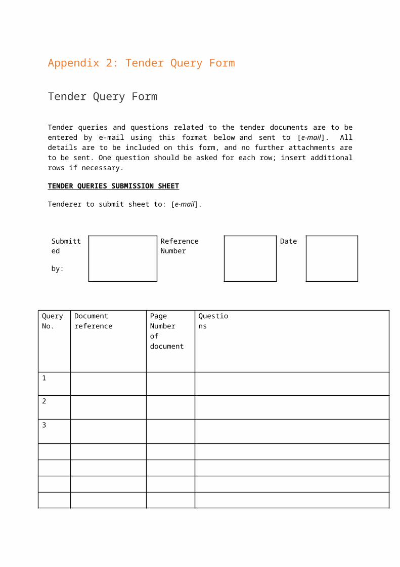
Appendix 2: Tender Query Form
Tender Query Form
Tender queries and questions related to the tender documents are to be entered by e-mail using this format below and sent to [e-mail]. All details are to be included on this form, and no further attachments are to be sent. One question should be asked for each row; insert additional rows if necessary.
TENDER QUERIES SUBMISSION SHEET
Tenderer to submit sheet to: [e-mail].
Submitted
by:
Reference Number
Date
Query No.
Document reference
Page Number of document
Questions
1
2
3

Appendix 3: Framework agreement[Separately published]

Appendix 4: General Conditions[Separately published]

Appendix 5: Statement of Consortium
In case of a consortium each consortium member should sign this statement.
The undersigned hereby declare that [name consortium member] is designated by the consortium to act on its behalf in purposes of the tender procedure and the framework agreement and shall have the authority to bind the consortium and is the sole interlocutor for all contractual and financial aspects.
The undersigned hereby declare that the composition of the consortium will not be modified except with the prior written authorization of the Contracting Authority.
The undersigned hereby declare that the consortium members will have joint and several liability towards the Contracting Authority and the Participating Contracting Authorities in both the tender procedure and any contract awarded to us as a result of it.
The reason to form a consortium is the following:
Specify the role, qualification, experience and performance part of the contract of each member of the consortium:
Name leading partner
Role
Qualification
Experience
Performance part contract
Signature
Date
Name consortium partner
Role
Qualification
Experience
Performance part contract
Signature

Date
Appendix 6: Statement of Subcontracting
In case of subcontracting the tenderer and each subcontractor should sign this statement.
The undersigned hereby declare that the tenderer intents to subcontract the following part of the contract to [name subcontractor]:
In addition, the undersigned hereby declare that the tenderer is the prime contractor and contact for the Contracting Authority during the tender procedure and the performance of the framework agreement. Tenderer is fully responsible for the compliance with all obligations under the framework agreement.
Name tenderer
Signature
Date
Name subcontractor
Signature
Date

Appendix 7: Statement Other Entity
The tenderer (consortium) should submit this statement for each other entity the capacities of which it relies on.
The undersigned hereby declare that [name tenderer/consortium] with regard to selection criterion [name selection criterion] as set out in paragraph [paragraph number] of the tender document, will rely on the capacities of [name other entity] and that [name tenderer/consortium] will have at its disposal the resources necessary for the performance of the contract.
Contact details other entity:
Name:
Address:
Telephone:
E-mail:
Furthermore, the undersigned hereby declare that [name other entity] fulfills solely or jointly with [name tenderer/consortium] the above-mentioned selection criterion (add evidence).
If the Contracting Authority decides to conclude the framework agreement with [name tenderer/consortium], the undersigned hereby declare that they will be jointly liable for the execution of the contract. Please note that this statement only applies if the tenderer (consortium) relies on the capacity of other entities with regard to criteria relating to economic and financial standing (paragraph 6.1 (insurance) and/or paragraph 6.2 (turnover).
If the Contracting Authority decides to conclude the framework agreement with [name tenderer/consortium], the undersigned hereby declare that [name other entity] will perform the part of the contract for which these capacities are required. Please note that this statement only applies if the tenderer (consortium) relies on the capacity of other entities with regard to criteria relating to technical and professional ability (paragraph 6.3 (experience).
Name tenderer
Signature
Date
Name other entity
Signature

Date

Appendix 8: Uniform Single Procurement Document (ESPD)
[Separately published]
Appendix 9: Reference Form
Tenderer shall submit one reference form for each reference contract.
The Contracting Authority reserves the right to contact the client/contracting authority of the reference contract.
Identification client/contracting authority
1) Name
Postal address
2) Contact person
Telephone
Reference contract
3) Start date of the contract
Completion date contract
Reason termination contract
4) Value of the contract (euro’s excl. VAT)
5)
A brief description of the reference contract, which provides evidence that the experience requirement is fulfilled.
6)
If performed in a consortium: the part (%) of the contract performed by the tenderer itself.
The tenderer (consortium) declares that the above-mentioned reference contract is fullfilled satisfactory to the client/contracting authority.
Name tenderer
Signature

Date
Appendix 10: List of Minimum Requirements

Dear potential procurer of a Personal Protective System (PPS),
The challenge brief template below is based on the original Smart@Fire PCP challenge brief. As the original PCP challenge brief resulted out of elaborated needs assessments, extended state-of-the-art studies and several innovation platform sessions (see annex 2), the requirements mentioned in this template will probably be in line with your specific needs and in result can be used as a starting point for the final procurement challenge brief. Of course, you can adapt the tender requirements to your own needs which might differ from what is stated below.
In order to help you select a good set of requirements we’ve described the journey towards the creation of these requirements in yellow below. These parts in yellow are only used to give you the right context and can be removed out of the final challenge brief.
Kind regards,
The Smart@Fire Team
Tender DocumentChallenge Brief

Index0. Context of Smart@Fire and the preparation of the Challenge Brief Template
430.1. The Smart@Fire Pre-Commercial Procurement (PCP) process.................................43
0.1.1. Positioning of the PCP tender.................................................................430.1.2. Pre-commercial Procurement in phases.................................................440.1.3. Preliminary Stage: Needs Assessment – Priority User needs..................460.1.4. Preliminary Stage: The State-of-the-Art..................................................471.1.2. Main challenges to be tackled in the scope of Smart@Fire beyond the state-of-the-art.....................................................................................................491.1.3. First Stage: The market consultation - Innovation Platform....................501.1.4. Second Stage: The Pre-Commercial Procurement..................................52
1. Scope of the Tender 521.1. General objective of the tender: Purchase of [#] PPS systems...............................521.2. PPS tender scope....................................................................................................531.3. PPS design constraints............................................................................................57
2. Appendix 1: Functional Requirements 592.1. Chapter structure....................................................................................................592.2. Priority use-cases in the scope of the Tender..........................................................592.3. High-level functional requirements for the PPS in scope of the Tender...................602.4. Functional architecture of the PPS in scope of the Tender......................................64
1.1.5. Actors.....................................................................................................661.1.6. Functional building blocks enable key use-cases....................................671.1.7. Functional Requirements of the functional building blocks.....................69
Definitions
Personal Protective System (PPS): all parts of the equipment worn by an individual fire fighter including auxiliary elements and that protect the individual from hazards to his health and safety. All parts from head to toes and from skin to outer layer are included. The PPS includes (non-exhaustive list): Personal Protective Equipment (PPE), non PPE clothing (i.e. non certified clothing), ICT hardware and software, data logging, monitoring sensors, warning systems, localization equipment, … Accurate monitoring and warning for both the individual fire fighter and the incident management are part of the PPS.
Throughout the document PPS may also be referred to as smart PPS, highlighting the technological ICT aspects
Throughout the document the scope of the tender is referred to as PPS nerve system, an associative term reflecting both the standard PPE turnout gear and core

ICT subsystems like communication network and data transfer, feedback mechanisms towards the firefighters and intervention coordinating officers, and intelligent processing units monitoring measured parameters and generating alert recommendations.

0. Context of Smart@Fire and the preparation of the Challenge Brief Template
Every year, more than 100 firefighters lose their lives while saving others. Few public services exist where personal safety is more important and the potential for technological innovation to improve the provision of services is higher than with the fire fighters. To reduce the risks associated with firefighting, huge potential lies in the integration of innovative ICT-solutions (sensors, processors, cameras, wireless transmission...) in a smart Personal Protective System. As the ICT-solutions available on the market in 2012, did not yet provide full satisfaction, the Smart@fire project was initiated to stimulate the development of an end-user oriented Personal Protective System with the objective of reducing the risks associated to firefighting.
0.1. The Smart@Fire Pre-Commercial Procurement (PCP) process
0.1.1. Positioning of the PCP tender Although research for smart textiles and Smart PPS was already conducted through numerous research projects on local and European level in 2012, none of these programs were advanced to the state of being able to present a working prototype that is ready for practical day-to-day use in a fire-fighting environment, due to the specific trade-offs of the fire and rescue niche:
1. State-of-the-art problems like indoor penetration of communication and localization are broader technological problems than just for fire and rescue applications. As such in affiliated research projects and commercial system developments, more attractive sectors such as defense, security, retail or utilities are chosen by manufacturers.
2. The fire and rescue market consists of a fragmentized procurement landscape with in general rather limited budgets (at least compared to military, security, etc.). Under these conditions it is hard to unite on selected user requirements and push these onto vendor development roadmaps.
3. The operational environment of the firefighter varies from a complex intervention in an urban confined environment to a forest fire in an open area to a technical intervention on the highway. All these specific conditions have a common need for an underlying system architecture (for communication of data for example). However, this architecture should be made flexible to allow for other functional configurations, which is under normal market conditions not easily achieved.
4. These user requirements cover all together robust operation, easy maintenance and high performance, at relatively low cost. These trade-offs are just not simply balanced.
In result, Smart@Fire was started from a concrete need for which the market in 2012 could not offer a suitable solution and R&D efforts remained to be performed by suppliers. While procurers, fire brigades and first responders were capable of describing the desired outcome or effect of an innovative solution, a regular procurement exercise would not lead to a solution. Other procurement

instruments provided a better fit, such as Pre-Commercial Procurement (PCP) which has the potential of spurring suppliers to enter into an R&D development.
Pre-commercial procurement aims primarily at reducing the risks inherent to R&D in order to avoid1:
procurers to purchase the development of technologies already available on the market, but not responding to their real needs;
procurers to purchase R&D that is technically/technologically too challenging and unrealistic to result in an industrial cost-effective application.
Taking these two points into account a phased approach was not only needed but also required in order to achieve the goals of a PCP.
0.1.2. Pre-commercial Procurement in phasesFor the Smart@Fire-PCP we adopted a methodic approach, covering following subsequent stages, described hereafter:
Preliminary stage: Needs assessment, defining end-user requirements, state-of-the-artFirst stage: Innovation Platform as market consultation instrumentSecond Stage: Joint Pre-Commercial Procurement: development of innovative Smart@Fire Personal Protective Systems in three stages (Solution Exploration, Prototyping, Test series of first products)Third Stage: Final Joint Procurement of Smart PPS
In subsequent chapters of this document the syntheses of the outcomes obtained through the needs assessment, state-of-the-art-study and innovation platform are described.
Note that the challenge brief template, while providing an overview of the insights captured during the preliminary, the first stage and the second stage, in essence only reflects the third stage: The Final Joint Procurement.
1.1.1.1. Preliminary stage: Needs assessment, defining end-user requirements, state-of-the-art
A needs assessment has been performed in order to detect updated end-user requirements and innovation expectations of the purchasing partners (fire fighter brigades/ first responders/ central procuring entities). In the proposed methodology, innovation is driven by the end-user, more in particular the end-user requirements and needs. It is important to perfectly understand these pain points and fully describe new functional solutions, existing alternatives and quantified added value.
From a technological point of view, a state-of-the-art study was carried out to allow defining the actual highest level of development in the sector. Given the numerous projects and studies concerning the development of Smart PPS that have been carried out during the past decade, this phase started by going through these works in depth, gaining insights, and distilling all elements that may lead to a pin-point formulation of the firefighter’s real and unanswered needs.
The outcome and findings of this phase allowed setting up the Innovation Platform.
1 Wilkinson report, “Public procurement for research and innovation: developing procurement practices favorable to research and innovation”, 2005

1.1.1.2. First stage: Innovation Platform as market consultation instrumentThe Innovation Platform has been organized as a consultation platform, bringing together the buyer side (the public purchasers expressing a specific need or request) and the supplier side (private companies, R&D organizations, Research Centers, industry sector organizations) in a series of plenary meetings, group work sessions and bilateral contacts. The primary goal of the Innovation Platform was the identification of the innovation potential form an end-user perspective and from a technological point of view. The convergence between good understanding of and access to the state-of-the-art with the innovation expectations (end-user requirements of fire fighters and first responders) kept in mind allowed us to identify the innovation potential.
By setting up a consultation platform a bridge is created between the demand and the supply side, and an opportunity emerges for a structured interaction between the market and contracting authority. The suppliers acquire knowledge about the interest and intentions of the procurers. On the other side the procurers obtain the necessary information to evaluate whether their own needs are matching with the possibility for the market (suppliers) to fulfil these needs.
1.1.1.3. Second stage: Joint Pre-Commercial Procurement: development of innovative Smart@Fire Personal Protective Systems
The findings and insights gathered throughout the Innovation Platform were translated into a final report and allowed the preparation of the Joint PCP. The PCP tender documents covered primarily the prototype scope, the priority user requirements to address, functional requirements of the underlying prototype modules, etc. The objectives of this phase were organized in 3 phases:
1. perform solution exploration and design: during this stage of 4 months, four selected suppliers (or consortia of suppliers) further elaborated the detailed design of their proposed solution (or set of solutions).
2. develop joint-workable prototype(s): during this stage of 8 months, the three chosen suppliers with the best solution design (as assessed by an evaluation committee) develop their own prototypes in parallel.
3. produce and test initial batch of finalized PPS prototypes (10 items): during this stage of typically 6 months, 2 suppliers remain to ensure a future competitive market. Their final productized solution batch of 10 items was validated through field tests executed in the training centers of SDIS13 in Aix-En-Provence.

Note that suppliers which were not part of these PCP phases or were not withheld throughout the evaluation and selection during the Joint PCP can still participate in this Final (Commercial) Procurement call.
Section ‘Scope of the Smart@Fire PCP: plan of attack’ elaborates these stages and affiliated timeline/activities/deliverables.
Only this stage is reflected upon in the current tender launch.
1.1.1.4. Third stage: Final Joint Procurement of Smart PPSThe findings and insights gathered throughout the Innovation Platform and the PCP phases were translated into this challenge brief for the joint procurement placed by [one of the project partners or other joining procurers of Smart PPS within the European Union] to acquire these newly developed innovations in commercial volumes.
0.1.3. Preliminary Stage: Needs Assessment – Priority User needs
For the determination of needs and requirements of the end users, a combined approach was applied:
- large-scale survey- in-depth discussion sessions with user groups
The survey was sent to approximately 4.000 contacts from all Member States of the European Union. The survey received 961 end user responses from 16 EU member states.
In parallel, in-depth discussion sessions were organized together with representatives from fire brigades from Belgium, UK & France to list firefighter needs with regards to smart PPS and starting from the vision below (as expressed by the fire fighters themselves):

“We are looking for a solution that allows to monitor and measure the environment (persons, equipment, external conditions)to determine the hazard-level (safe, hazardous, threatening)by both passive (running in background) and active (deployed on demand) systemsthat translate in alerts or alarms being givenand accordingly adjust the safety by whatever means necessary (e.g. textile)so that safety and comfort are optimally balancedirrespective of the context (fire in building, fire in forests, highways, …)”
A list of 54 use cases was collected from representatives of different user groups representing the actual user needs. The added value and relative priority of use cases were estimated by fire brigades themselves. From Belgium ~20 officers/fire fighters from different cities participated, in France ~15 officers/fire fighters from dept. Bouches-du-Rhône, and in UK ~35 officers/fire fighters from all over UK.
By using the Planning Poker methodology, use cases have been objectively validated & prioritized as the method stimulates people to voice their opinions, thoughts and concerns. This way, drivers/reasoning behind use case validations are revealed and understood.
The conclusions of the needs assessment are unfolded hereafter.
In conclusion, a smart PPS is highly innovative for the end-users. End-users encompass different actors, the firefighters, intervention coordinating officer, PPS manager, etc. This is proven by the high amount of “WOW” use-cases, signifying a high added value compared to the present alternatives today. Next to that, these needs are common across European firefighters as high commonality is noted between the distinctively consulted user-groups across Europe through in-depth working sessions and via the survey. Primary user requirements hold:
- Localization of the firefighter and his team, in buildings and open areas, displayed on a map, made available to the firefighter and the intervention coordinating officer.
- Remote parameter monitoring and historical logging, making the info accessible via an intuitive dashboard for the officer (e.g. a map), enriched with the status of the team, their PPS, and the environment, enabling to set thresholds, generate (automatic) alerts.
- Monitoring the environment, more in particular temperature, temperature evolution, hotspot detection and presence of explosive gasses.
- Specific PPS requirements as: avoiding sweat being turned into steam inside the turnout gear and active illumination to be seen as first responder.
- General requirements as robustness under mechanical friction, maintenance, repair, cleaning, with easy mounting/dismounting of the ICT and ideally with self-assessment.
Use cases that were distinguished as ‘low priority’ were:
Consultation of body functions (heart rate, body temperature…) by the firefighter him-/herself
PPE enhancements such as a protective airbag, additional cooling/heating, walking markers…

Consultation of building fire detectors by the firefighter Firefighters setting safety thresholds for themselves; Department head setting safety thresholds. Access for representative of internal affairs to similar information as the
department head
0.1.4. Preliminary Stage: The State-of-the-Art
1.1.1.5. ContextThe envisaged innovation as summarized by the needs assessment intends to be a breakthrough compared to the actual field systems. Many, if not all components to be used, will be new and have to be integrated in a way that guarantees optimal protection in real life situations. This translates into expectations of substantial R&D to be carried out at integration level, with certain implications and R&D at component level.
1.1.1.6. Approach and resultsThe state-of-the-art study comprised following dimensions:
- An investigation of all projects logged within the EU and national databases to locate projects related to smart textiles, Smart PPS, high-end sensors, life support monitoring with a focus on final results and lessons learned.
- Execution of an IP scan, analyzing patents in order to understand the major players, recent developments and breakthroughs...
- Evaluation of relevant recent developments published in scientific journals- Web search to identify existing available products and suppliers
Results are conclusive. A lot of activity is spotted around the priority user needs domains of localization, environmental sensing, remote monitoring and data relay, both in research domains as by commercial product/system providers:
- EU and nationally funded research projects: at least 40 recent projects have been identified regarding firefighter smart textile and/or equipment research, of which 14 are directly related to firefighter PPS. But very few smart textile innovations come to the market, for sure not in the area of PPE/PPS. These research projects focus(ed) primarily on:
o Positioning and localization: integration of existing localization systems using GPS, inertia-based relative localization devices (incl. accelerometers, gyroscopes, etc.)
o Environmental sensing: primarily temperature and toxic/explosive gasses
o Physiological parameter sensing (body temperature, heart rate, breathing rate, sweat,…) and health monitoring
o Active illumination, walking markers, and heating/coolingo Data processing and logging to generate alerts, including simple control
functionalities for the firefighterso Intuitive visualizationo Communication and remote alert generation
- Multiple patents in this area have been filed. However, the minority of these applications is granted so far. These mostly European and US patents focus on:

o Positioning sensors, o Environmental parameter monitoring (temperature and explosive
gasses), o Physiological parameter monitoring (body core/skin temperature, heart
rate, sweat levels, etc.),o Communication technology and remote alert generationo Intuitive control (UI) functions for the firefighters
- Over the last decade research into smart textiles has exponentially emerged, as indicated by the large number of scientific publications that are found on the subject of smart textiles. Across the more than 200 publications extracted from the online academic database Web of Science provided by Thomson Reuter, the 50 most appearing words in the keywords are visualized in the Wordle below.
- Multiple developed prototypes show promising results. An exploratory websearch revealed rapidly multiple industrial initiatives active on fire & rescue applications and a multitude of technologies. However, nearly all face a major problem of day-to-day practical usability. ‘A suit full of working ICT is no good if you cannot wash the suit after an intervention.’ These developed prototypes primarily encompass following functionalities and technologies
o Positioning within buildings and localization of colleagues in the fieldTechnologies: GPS, inertial sensors, beacon/antenna-based solutions, etc.
o Environmental sensing and monitoring of temperature and toxic/explosive gassesTechnologies: standard sensor technology
o Physiological sensing and monitoring of body temperature, heart rate, dehydration levelsTechnologies: standard sensor technology
o Intuitive feedback and control functions for the firefighterTechnologies: audio, visual feedback via lights or even via Head-Up Displays, Head-Mounted displays (but at conceptual level…), etc.
o Alert generationTechnologies: auditory sirens, auditory speech, flashing lights on sleeve/waist, etc.
o Intuitive visualization for the remote intervention coordinating officerGraphical user interface (GUI), ruggedized laptops/tablets, etc.
o Remote intelligent data processingRule-based reasoning, artificial intelligence (learning, neural networks), etc.
o Communication relay

Mobile Professional Radio (Tetra), Mobile Ad-hoc Networks (Manet), Zigbee, Bluetooth, MyriaNed, WiFi, etc.
o ICT and textile integrationWoven-in electrical fibers, glued-on cabling, integrated sensors, designed-in cabling, etc.
o Efficient and safe power supplyIP67 safe power supply to wear underneath the turnout gear, etc.
1.1.2. Main challenges to be tackled in the scope of Smart@Fire beyond the state-of-the-art.
Technology wise, the Smart@Fire Project goes beyond current state-of-the-art in the following ways:
- Collect a comprehensive list of end-user requirements as well as technological feasibility aspects (taking into account projected technological progress). This has been realized in the Innovation Platform
- Identify and report on gaps and R&D needs. This will also be realized in the Solution Exploration phase.
- Specification and building developments of actual prototypes combining departing from state-of-the-art technologies and going beyond these on well-identified sources of technological risk. (as explained in subsequent sections)This will be realized in the Prototyping phase.
- Testing the feasibility of (small scale) production of complete products. This will be realized in the Batch production phase.
This project aims to develop a final product which incorporates all the functionalities of the developed prototypes, but which is also a completely finished, ready-to-use product through PCP. In that sense it is complementary to previous projects by offering two novel aspects:
- Clear focus on the integrated practical usability of the developed solution. Practical usability meaning: durability, reliability, ergonomics, in compliance with overall list of firefighters tasks (e.g. as specified in BE by KB). Integration meaning (i) collaboration between the different technological devices on functional level; (ii) potential integration of different technological components into 1 housing; and (iii) intelligent coupling between the technological devices and a traditional PPE turnout gear.
- Focus on mass production feasibility and keeping this in mind from the beginning.
In conclusion, sufficient projects, market actors, etc. have been identified which are active in the fire and rescue field, and more in particular on the common user priorities (positioning, environmental sensing, remote monitoring…). It is observed that nearly all identified projects, prototypes, market actors operate internationally, beyond Belgium, France and UK. Often a direct/indirect link with military initiatives is notified. However, as military application requirements are much more demanding, these market solutions come at a much higher manufacturing cost, and hence out-of-market pricing for civil applications like firefighting. These market solutions need to

be redeveloped, redirected towards fire and rescue applications and its buying market.
1.1.3. First Stage: The market consultation - Innovation Platform
1.1.3.1. TimingThe Smart@Fire innovation platform was organized during the months September and October of 2013. The final presentation of the gathered insights was held October 10th 2013.
1.1.3.2. ObjectivesTo better protect firefighters, the Smart@Fire project envisions the next generation Smart Personal Protective System (PPS): an integrated system covering ideally localization and positioning, environmental sensing, body monitoring, data transfer and visualization for remote coordination, data interpreting intelligence, intuitive audiovisual feedback, smart textiles, etc. in order to successfully address all the priority user needs. However, not all these functionalities are necessarily withheld in the scope of the smart PPS pre-commercial tender, given the PPS prototype only focuses on a well-defined scope, delineating the innovation potential.
Principal objective of the innovation platform was to determine these priorities of a smart PPS prototype throughout the innovation platform discussion sessions with demand and supplier side. The priorities are presented hereafter.
1.1.3.3. Synthesis of the innovation platform insightsA smart PPS holds a high innovation potential from technological perspective. This innovation potential has been identified across the different angles of a smart PPS, in line with the key user requirements, listed below:
Focus area 1: ICT localization systems embedded in PPS Focus area 2: PPS sensors/active subsystems and their integration in smart
textiles Focus area 3: ICT solutions for remote connectivity & visualization systems in
PPS Focus area 4: Integration of ICT solutions with textile
Platform sessions focusing on these areas allowed understanding the vendors’ capabilities to satisfy the most important & commonly shared user needs. The common needs in terms of robustness & maintainability have been applied in all sessions as a boundary condition. If necessary, all constraints imposed by any of the procurers’ countries (i.e. the minimum requirements set), have been taken into account in a similar way.
Putting these angles together, the overall innovation potential of a smart PPS resulted in a number of clustered challenges, of which 1 principal and 4 smaller, summarized below.
CHALLENGE 1: PPS central nerve system: system architecture, communication, localization & interfaces
Challenge 1 covers multiple elements listed hereafter. For each element a number of insights are described, reflecting the main sources of complexity.
The PPS central nerve system architecture:

Communication network with sufficient indoor penetration and near real-time update rate towards the intervention coordinating officer
Balanced trade-offs between distributed and central processing, scalability of system, local performance vs. remote responsiveness (online vs. offline operation), interfaces, etc.
Limited integration with textile (underwear, turnout gear, …): Woven-in, layered-on ICT-textile integration comprises too many risks w.r.t
manufacturing costs, durability, etc. and is left out of the scope of the PCP tender. Limited integration between the ICT subsystems and the standard turnout gear is preferential.
Cabled and/or wireless. When cabled: easy mounting/replacing of cables/connectors; durability of cables/connectors; dealing with different turnout gear sizes; integrating UIs. When wireless: limiting interference; easy start-up and self-assessment of correct operations via minimal # UI’s
Electromagnetic shielding of the different devices (sensors, processing unit,…), without implementing military-grade measures.
Localization engine: A hybrid localization system (preferentially GPS with inertial subsystem) with
limited indoor drift. A relative track & trace map, enabling ‘meet point’ and ‘recovery path’
instructions. Available Cartesian coordinated maps (e.g. Google maps) used as overlay.
Beacon-based solution instead of inertial at increased risk, principally fast & accurate deployment and TCO.
Intuitive user feedback (restitution, visualization): For the intervention coordinating officer: intuitive UI dashboard, conform way
of working. For the firefighter: Full usability satisfaction for at least 90% of the users.
Coupling via defined application interfaces (e.g. Bluetooth application profile) with (Standalone) environmental temperature measurement device Physiological monitoring device Optional, when available: (standalone), cheap, simple and robust explosive
gas detector (e.g. indicating the presence of explosive gasses without measuring ppm details)
CHALLENGE 2: Sweat absorbing multilayer underwearA pure textile issue, needing effort to convince firefighters and procurement agencies to review tenders and firefighters’ comfort balance (e.g. skin resistance). Note that it is not the goal to develop a new better performing sweat absorbing multilayer material, these materials exist. Underwear in this context reflects anything worn underneath the turnout gear.
CHALLENGE 3: IR thermal hotspot detectorFinding the balance between a cheap, miniature IR thermal imaging sensor/camera with relevant resolution and detection range in high temperature environments holds significant risk.

CHALLENGE 4: HMD/HUD firefighter visualization systemProviding visual feedback to the firefighter via helmet mounted displays (HMD) or head-up-displays (HUD) in the helmet visor holds major risks in balancing trade-offs between cost, ergonomic use (brightness, contrast, “see-through”, etc.), robustness.
CHALLENGE 5: “BE SEEN” omnidirectional active illuminationActive illumination to achieve omnidirectional “be seen” could be simply solved via a cheap, standalone clip-on/Velcro system (limited integration with textile). The risk is to make it usable to allow for easy operation (somewhere fixed on the firefighter suit), but not being destroyed in an intervention due to the increased temperature or mechanical friction. An alternative cabled solution impacts design and integration complexity (durability of connectors, cabling, etc.).
Note that explosive gas detection and physiological monitoring are not withheld within the innovation potential from technological perspective of a smart PPS, as for these building blocks mature technological solutions exist on or close to the market. It is not the goal to develop a next generation of better, smaller, cheaper explosive gas detectors or physiological monitoring devices. The real added value is the coupling with the PPS central nerve system, captured in Challenge 1.
1.1.3.4. Conclusions of the innovation platformThe conclusions of the Smart@Fire innovation platform situate on three levels:
- As first conclusion: a smart PPS is highly innovative for the end-users, as indicated by the high amount of high-value use-cases.
- As second conclusion: a smart PPS holds a high innovation potential from technological perspective, as described in previous section.
- As third and final conclusion, given the high innovation potential both in terms of added value for the end-user as in terms of risk from technological and implementation perspective, significant research and development effort is needed to reduce the risks associated to the technologically innovative elements to enable the high-value use-cases for the end-users, firefighters and officers. As today a commercial smart PPS is not available on the fire and rescue application market, it is recommended to initially launch a pre-commercial development phase. During this phase, focus is laid on reducing these risks with limited means.
In consensus with the end-users (i.e. firefighters and affiliated public procurement agencies) and the European Commission, the priority challenge for the PCP tender scope covers primarily CHALLENGE 1, PPS central nerve system (incl. standard turnout gear ‘integrated’ with ICT subsystems covering system architecture, communication, localization, visualization, interfaces, etc.). CHALLENGE 2, sweat absorbing multilayer textile solution, is left out as being a pure textile challenge. Regarding CHALLENGE 3 and 4, the IR thermal hotspot detector and the HMD/HUD firefighter visualization system, it is recommended to dedicate a similar but different project to solving these. CHALLENGE 5, “BE SEEN” omnidirectional active illumination, qualifies to be withheld within the minimal scope of the prototype, but it is currently left out, taking into consideration the project budgetary and timing constraints.
1.1.4. Second Stage: The Pre-Commercial ProcurementDuring the second stage (PCP), suppliers (supplier consortia) were challenged to create a prototype addressing all requirements stated in the challenge brief. On

November 8, the delivered prototypes were tested in SDIS13 training facilities in Aix-En-Provence.
Resulting out of the insights gathered during the second stage, a couple of small adjustments were made to the original set of requirements. The final set of requirements can be found below.
Findings out of the prototype testing days can be found next to the challenges in yellow.
1. Scope of the Tender1.1. General objective of the tender: Purchase of [#] PPS systems
Every year, more than 100 firefighters lose their lives while saving others. Few public services exist where personal safety is more important and the potential for technological innovation to improve the provision of services is higher than with the fire fighters.
To reduce the risks associated with firefighting, we’re convinced huge potential lies in the integration of innovative ICT-solutions (sensors, processors, wireless transmission...) in a smart Personal Protective System. The innovation potential for the firefighters of the PPS central nerve system is captured through the priority use-cases listed below.
The objective of the tender is to deliver a batch of # PPS solutions that can effectively realize the below mentioned use-cases for the end-users. (Note that in the table below ‘ICO’ refers to ‘Intervention Coordination Officer’, ‘FF’ to firefighter, ‘T’ to temperature, ‘RCA’ to ‘Root Cause Analysis’)
Priority use-caseAn ICO consulting a "relative" map to locate the FF teamsAn ICO consulting a "relative" map to locate the FF teams enriched with env. ΔT, An ICO consulting a "relative" map to locate the FF teams enriched with equipment statusAn ICO using an intuitive visualisation system and semi-automated data interpretationAn ICO informing the FF by generating an alert (using the available data)A FF using an intuitive feedback system not distracting his operationsAn ICO escalating alerts/available data to create an aggregated viewA FF measuring env. Parameters (temperature and evolution)A FF, PPE manager relying on self-assessment of available, coupled sensors, devicesA trainer using similar remote monitoring available info to improve traineesA department head using historical logging of available data for RCA, audit trails,…A FF measuring env. Parameters (explosive gasses)
For an exhaustive description of the priority use-cases, the functional reference architecture of the PPS pre-commercial tender scope and the detailed functional requirements, reference is made to Appendix 1:Functional Requirements.
1.2. PPS tender scopeCHALLENGE : PPS central nerve systemThe PPS central nerve system, an associative term, reflects both the standard PPE turnout gear and core ICT subsystems like communication network and data transfer, feedback mechanisms towards the firefighters and intervention coordinating officers, and intelligent processing units monitoring measured parameters and generating alert recommendations. These functional modules hold the innovation potential for the firefighters and as such form the PPS tender scope.
While the real innovation potential lies more on practical applicability in-the-field, note that functionalities as central data aggregation, escalation, and data storage are as well included in the scope. These functionalities may be performed on the technological equipment of the intervention coordinating officer, on existing infrastructure of the firefighter truck, on additional (networked) infrastructure to be added on the firefighter truck, in a virtual datacenter connected to the firefighter truck, or yet another configuration (as described in the Appendix 1: Functional Requirements).
The chosen set-up shall however focus on aligning maximally with existing available infrastructure, hence minimally adding extra infrastructure. (See Appendix 1: Functional Requirements and Awarding Criteria IX: TCO of the solution, as stipulated in Invitation to Tender). For an exhaustive description of the priority use-cases to enable, the functional reference architecture of the PPS tender scope, the detailed functional requirements (as identified today) and the testing prescriptions, reference is made to Appendix 1: Functional Requirements.
Following sections elaborate on the functional elements of the PPS central nerve system.
The PPS ‘central nerve’ system encompasses following building blocks and affiliated innovation potential from technological perspective. In other words: the PPS tender scope comprises a number of functional modules.
The overall central nerve system architecture:- Communication network with sufficient indoor penetration (sufficient to
successfully realize the envisaged test scenarios), optimized data rate, data model, data preprocessing, and near real-time update rate towards the intervention coordinating officer (by maximizing the scalability trade-off of deployed network nodes vs. update rate). Different communication technologies exist, but all with different intended usage: intended use of Professional Mobile Radio (PMR) is for trunked mode operation (TMO) and direct mode operation (DMO) voice and limited data. Mobile ad-hoc networks (MANET) for data and selected compressed images, Ultra Narrow Band (UNB) for small data sets at low update frequencies.
- Setting-up the right architecture is key and holds significant risk. Main sources of risk comprise defined the data model, setting the balance between distributed and central processing taking into account trade-offs between local processing performance of selected data and responsiveness when remote relay of data (e.g. in case of physiological alerts), defining interfaces for hierarchical aggregation and escalation, building the suited data model, allowing for online and offline operation with careful consideration of polling and synching events, coping with the multimodality in firefighter user

restitution means, modularity allowing for coupling with new peripherals (e.g. sensors), scalability of the system, etc.The objective is not to develop a ‘usine-a-gaz’ allowing for endless flexibility, merely it is the goal to ’do the right things’ allowing for some future improvement and coupling with new peripherals. It should be thought through which future peripheral devices might be coupled. Also start-up of the system should be in line with present routines when preparing for an intervention and arriving at the scene. Additional manipulations by the firefighter should be minimized.
Limited integration with textile (underwear, turnout gear, or …):- Woven-in, layered-on ICT-textile integration implies too many risks w.r.t
manufacturing costs, durability, etc. and as such is left out of the scope of the PCP tender. Integration between the Smart PPS technological ICT equipment and standard PPE turnout gear shall be kept to limited integrative measures such as well-designed pockets, inner-shell cabling textile tubes, inner-shell velcro strips, inner-shell belts, inner-shell slip knots, etc.
- Cabled (internally in the PPE turnout gear or between the PPE turnout gear layers) and/or wireless integration are allowed, with careful consideration of respective risks:
o when cabled: easy mounting/replacing of cables/connectors; durability of cables/connectors; dealing with different turnout gear sizes ; integrating multiple UIs.Under the assumption that the total duration of replacing the cabling designed in into the layers of the turnout gear can maximally take 15 minutes to not heavily impact the workload of the PPS maintenance crew, it is key to keep cabling as simple as possible. Ultimate goal is to reduce the risk so that a PPS maintenance responsible can easily carry out the replacement task, without specialized help of a textile specialist.Durability and robustness of operations refers both to the normal operational conditions (heat, chemicals, etc.) during interventions, as to the cleaning operations. Throughout the lifecycle of a turnout gear (5 to 8 years), around 20 to 25 cleaning operations are carried out, during which the turnout gear is subjected to special treatments, like restoring waterproofness, etc. This is not easily resolved. Easy (dis)mounting (and recuperating) the cabling could lighten the risk severance, but connectors remain an issue, especially those used to connect external sensor devices. As such, these externally exposed connectors are not preferential for the PPS prototype.Concerning the multiple sizes of turnout gear, the assumption is taken that 3 variants will suffice for the 8 turnout gear sizes. The constraint is that impact on ergonomics is nihil. Furthermore, ‘only’ 3 variants do not impact manufacturing costs too much. Solutions incorporating “stretchable cables” are not envisaged given a higher risk severance on ergonomics, durability, etc.
o when wireless: limiting interference (cfr. data connectivity); easy launch , start-up and assurance of correct operations via minimal # UIs. Starting up the system should be straightforward, even in case there are several wireless interlinked devices on the firefighter. The firefighter should as fast as possible know that the system is fully operational in line with his time to arrive on site (order of magnitude of

5 to 10 minutes). Compared to a centralized system, a wireless approach is more complex, especially when the aim is to restrict the amount of UI’s to a minimum.Next to start-up and launching the system operational, this should be launched in the right configuration, with auto-detection mechanisms, etc. Again with minimal operations/manipulations required from the firefighter. Typically to select the right gear (and hence configuration) the firefighter relies on the intervention briefing by the security officer.Finally, tests need to be performed to make sure that the frequency spectrum is optimally used, balancing communication between sensor devices (body and environment) on the firefighter’s, localization system and radio communication towards the remote intervention coordinating terminal.
- Electromagnetic shielding of the different devices (sensors, processing unit,…), without implementing military-grade measures.
Localization engine:- A hybrid localization system (GPS + inertial) with limited indoor drift is
preferred. It is agreed by the state-of-the-art industry experts that in order to achieve a limited drift of <2m or <1% over track distance (whichever is largest) without reference position update, thorough testing should be set-up in indoor environments during fire and rescue applications. Effective localization measurements can be limited to 20’ (10 to 20 minutes suffices, given the capacity of a compressed air bottle amounts around 25 minutes.) These tests will further clarify any implications on design of the device and motion tracking modeling. It is believed that by implementing smart measures (e.g. transferring absolute position updates between team members or re-calibrating fast when standing still) the required performance level can be approached, within tradeoffs of the envisaged Smart@Fire PPS.Of course anything is possible for the right price, given the capability of navigating fighter jets through valleys for hours relying primarily on inertial measurement units.
- A relative t rack & trace map should enable ‘meet point’ and ‘recovery path’ instructions. In case a map of the environment is available (e.g. Google maps, or offline map created by UAVs) and the map is referenced w.r.t. absolute Cartesian coordinates, it should be used as e.g. an overlay.
- Beacon-based solution for localization can be incorporated at increased risk in terms of ease of deployment without losing accuracy and TCO. Note that it is not envisaged to deploy this solution over the complete building. Merely, the aim is to gradually, locally and virally grow the beacon network within the intervention area.In ideal situations (reasonably vast areas or rooms with wide angle of sight) when the beacons have been deployed in a good way, attaining an indoor accuracy of the order of magnitude of 1 meter is feasible, and hence the risk is relatively acceptable. Given that reality is often far from the ideal situation and taking into account the human error factor in the deployment of the beacons the real risk is estimated significantly higher and risk reduction is required.A precondition for a fast and qualitatively good deployment of the beacons requires insight of the firefighter in the context of the environment, e.g. to immediately determine the needed amount and maximal spread of the beacons to deploy. As it requires lots of field trials to train the firefighters and

consolidate the approach in a reproducible deployment procedure, the estimated risk is significant.
Intuitive user feedback (restitution, visualization):- For the intervention coordinating officer: an intuitive User Interface (UI)
dashboard, aligned with way of working should be developedIn France for example, the way of deploying firefighters occurs as follows: per truck there is a “penetration officer” coordinating typically 2 teams of firefighters. At a second coordination level, 1 “group commanding officer” coordinates up to 4 penetration officers. In parallel, a “security officer” who disposes of own firefighter couples focuses on the safety and potential rescue of colleague firefighters. So the GUI needs to be adaptive in the level of data aggregation/escalation and visualization.
- For the firefighter: Full usability satisfaction for at least 90% of the users.- Coupling via defined application interfaces (e.g. Bluetooth application profile)
with (Standalone) environmental temperature measurement device, as the goal of the PCP tender is not to develop a new environmental temperature sensor, but merely interface with it via a standardized interface.
- Existing physiological monitoring devices to capture hearth rate, breathing rhythm, etc.
- Optional, when available: (standalone), cheap, simple and robust explosive gas detector (e.g. indicating just the presence of explosive gasses). Note that will not develop a new environmental explosive gas detector, but merely interface with it via a standardized interface, under the precondition that a qualitative cost-efficient gas detector is identified, as all deployed firefighters should ideally be equipped with such a device.
The innovation potential for the firefighters of the PPS central nerve system is captured through the priority use-cases listed below. The objective of the tender is to deliver a batch of # PPS solutions that can effectively realize the below mentioned use-cases for the end-users. (Note that in the table below ‘ICO’ refers to ‘Intervention Coordination Officer’, ‘FF’ to firefighter, ‘T’ to temperature, ‘RCA’ to ‘Root Cause Analysis’)
Enabled use-caseAn ICO consulting a "relative" map to locate the FF teamsAn ICO consulting a "relative" map to locate the FF teams enriched with env. ΔT, An ICO consulting a "relative" map to locate the FF teams enriched with equipment statusAn ICO using an intuitive visualisation system and semi-automated data interpretationAn ICO informing the FF by generating an alert (using the available data)A FF using an intuitive feedback system not distracting his operations (novisual.)An ICO escalating alerts/available data to create an aggregated viewA FF measuring env. Parameters (temperature and evolution)A FF, PPE manager relying on self-assessment of available, coupled sensors, devicesA trainer using similar remote monitoring available info to improve traineesA department head using historical logging of available data for RCA, audit trails,…A FF measuring env. Parameters (explosive gasses)

For an exhaustive description of the priority use-cases, the functional reference architecture of the PPS pre-commercial tender scope and the detailed functional requirements, reference is made to Appendix 1:Functional Requirements.
1.3. PPS design constraintsIt is important to know as tendering supplier that two main design constraints have been determined, the first with respect to buying budget orders of magnitude, the second with respect to applicable standardization and conformity assessment procedures. These design constraints are elaborated below:
Price of PPS: Today firefighter turnout gear prices vary around 600-750€ per piece (i.e. vest, trousers). In line with budgetary provisions, the price of the envisaged PPS final system is expected to amount to maximally 1500€ (order of magnitude) per firefighter PPS, including technological components, turnout gear garment and excluding helmet, additional hardware/software (ruggedized tablets/laptops, application servers, licenses, etc.) for the intervention coordinating officer.
This price indication provides tenderers a guideline when setting solution design trade-offs. Evidently, not only price per PPS is important, merely the awarding criteria, as stipulated in the Invitation to Tender document, focus on total cost of ownership throughout the lifetime of the PPS.
Standardization and guaranteeing safety: At all times the Smart@Fire PPS prototype and first batch of products should fulfill basic health and safety requirements. For the PPE turnout gear, health and safety requirements are safeguarded through existing directives and harmonized standard testing procedures (EN469). These directives do not apply to smart textiles, where ICT cables, sensors and actuators are integrated within the PPE textile.
On the other hand, for fire and rescue ICT-related products and systems, multiple levels of directives and standards are commonly complied with by suppliers: e.g. environmental standards for intended use in explosive environments (ATEX, IEC-Ex), radio & communication standards (RTTE), material related standards (REACH, RoHS), etc.
Suppliers’ products shall comply with these standards and directives, by obtaining necessary certification through test procedures via a recognized notified body ((if applicable for the intended use).
To omit any potentially blocking discussions, in the envisaged Smart@Fire PPS system, integration between the PPE turnout gear (textile) and the ICT technological systems is kept to a minimum. Some ICT technological systems (such as localization device, processing unit, batteries) may be worn underneath the inner shell of the turnout gear and can be decoupled from the turnout gear. As such known directives and standard test procedures apply (e.g. Ingress Protection Rating of IP67). Other ICT technological systems like sensing devices will equally be exposed to extreme conditions, but still not really integrated with the PPE turnout gear (as the technological risks are estimated too high). Again the different known directives and standard testing procedures apply.
Nevertheless, in addition to the known standards and directives for PPE and for ICT related firefighting products and solutions, it is recommended that the conformity assessment procedure of the Smart@Fire PPS prototype and first batch of

products describes a selected set of testing procedures to be performed with the PPS prototype/product as a whole (i.e. PPE turnout gear on manikin equipped with the supplementary ICT technological subsystems). These testing procedures are elaborated upon in Appendix 1: Functional Requirements.

Appendix 1: Functional Requirements
1.4. Chapter structureThis chapter covers the mandatory requirements of the PPS product. Each section answers a different key question:
Section 3.2: which priority use-cases (as indicated by the firefighters themselves) are to be realized by the PPS product?
Section 3.3: which high-level functional requirements form the basis of the PPS product?
Section 3.4: which functional building blocks constitute the PPS functional architecture, given the priority use-cases to enable?
Section 3.4.1: which key-actors are involved in the functional use of the PPS?
Section 3.4.2: for each use-case, which functional building blocks are needed?
Section 3.4.3: for each of these functional building blocks, which functional requirements are identified to be implemented by the PPS?
1.5. Priority use-cases in the scope of the TenderThis section elaborates on the priority user requirements, as indicated by the firefighters (end-users) themselves. The format used are use-cases:
As an <actor>, I can <perform an action, dispose of a system, etc.>, so that <my pain point is solved and added value is created for me>.
The key use-case are listed hereafter.
In the subsequent table, reasoning is provided why these use-cases are key for the end-users, as consulted in interactive user-group sessions in Belgium, France and UK.
1.6. High-level functional requirements for the PPS in scope of the Tender
While the previous section focuses on the key functional requirements from an end-user point of view, the current section aims at clarifying what this implies on functional requirements for the Smart PPS Solution to be designed & developed.
Following high-level functional requirements have been identified. These high-level functional requirements should be considered by tenderers as overarching requirements, to be met by the Smart@Fire PPS prototype.
- Configuration of the PPS system: different types of interventions require different functionalities (e.g. in a forest fire a lighter helmet and turnout gear is chosen/required), the system architecture should allow for flexible operation and configuration. 4 main configurations can be distinguished:
o Basic configuration: localization + remote connectivity + intuitive visualization
o Physio configuration: localization + remote connectivity + intuitive visualization + physiological monitoring
o Urban configuration: localization + remote connectivity + intuitive visualization + environmental monitoring
o Full functional configuration: localization + remote connectivity + intuitive visualization + physiological monitoring + environmental monitoring
- Autonomy: given that different types of interventions require different types of PPE according to norms (forest fire vs. urban fire in confined areas), a different set of functionalities is required (e.g. in forest fire no toxic gas detection or IR camera sight is required, only localization and communication suffice), and span different durations. A typical intervention in an urban setting with breathing apparatus takes 20 to 40min, depending on the intensity of the intervention in relation to the air volume in the bottle. In a forest fire situation, intervention times of up to 3 hours are noted in case of no excessive efforts, 1 to 2 hours in case of running. So in summary, the minimally required autonomy for the PPS system is about 2 hours when all functionalities are operational, and up to 4 hours in a forest fire configuration.
- Weight: Current firefighter turnout gear weight amounts around 25 to 30kg of which 3 to 4kg is due to turnout gear garment. The remaining weight covers boots, helmet, breathing apparatus, handheld illumination, water hose, etc. As a consequence, the Smart@Fire PPS prototype should be kept as lightweight as possible striving to maximally add 1-2 kg, well balanced around the body. This includes battery weight.
- Speed of deployment: today’s procedures aim to minimize the delay between the first alert arriving at the dispatch center and the arrival onsite. Typically, during daytime (and in the case of an online brigade), firefighters are given 3 minutes to get in the turnout gear, receive short intervention briefing on location and situation, and gather in the truck. (At night time this is 5 minutes). The breathing apparatus, water hoses, etc. are kept in the truck. They remain fixed during transit, resisting shocks up to 10g. The aim is to arrive on site within 5 to 10 minutes, so the time to launch the PPS ICT system
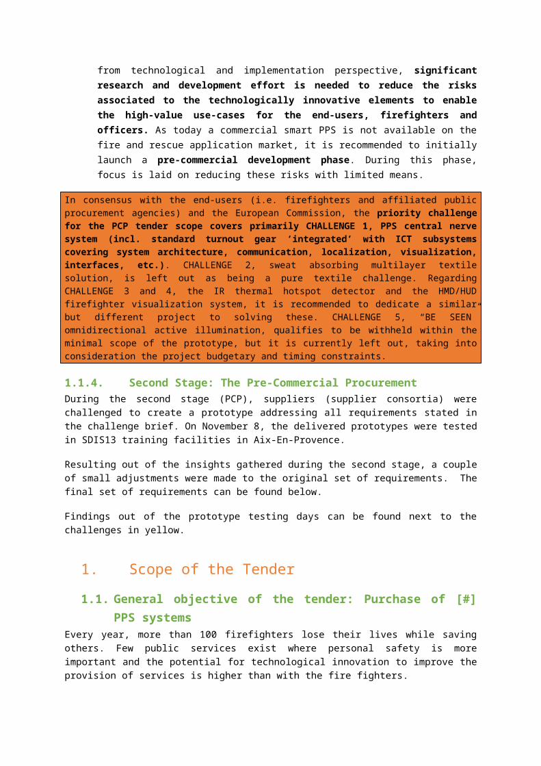
and reach the operational state is of the same order of magnitude (~10 minutes).
- Refresh rate of data transfer from the deployed firefighters in the field towards the remote intervention coordinating officer/command center is ideally performed in near real-time (~1Hz). This is considered sufficient to keep track of the firefighters’ movements as firefighters in the field move at limited walking speed.
- Accuracy of the localization system: in open areas an accuracy of localization of about 3 to 4 meters is sufficient. In confined areas, a higher accuracy is requested up to 1m. In confined areas the aim is to find a victim, make an assessment whether a person is on one side of the wall or the other, etc.
- Standard interfaces between wirelessly connected devices on the firefighter: in case for example a firefighter is equipped with wirelessly connected environmental sensing devices (e.g. temperature, explosive gas detection), the communication protocol applied should be a known standard (preferably Bluetooth) with known application profile and managed duty cycles for extended autonomy.
- Fraud proof: Fraud-proof inherently refers to measures against jamming and spoofing. Jamming refers to intentionally electromagnetically interfering with the system to make it unavailable. Spoofing is more advanced in the sense that the system is interfered by falsifying data without the system detecting it. Today, relatively cheap but narrowband jammers are on the market for around 40$. To jam on a broader spectrum requires significant emission power.Concerning making the system fraud-proof, the risk depends on how far measures are pushed. For fire and rescue applications, fraud countering measures should be implemented taking the assumption of normal civil environments. Military-grade measures are considered out of scope for this project.
- Lifecycle: today the average lifecycle of PPE turnout gears is ca. 8 years (with variation between 2 to 14 years (depending on the intensiveness of use, potential incidents during interventions, etc.). The lifecycle of the additional supplementary ICT components in the PPS should ideally corresponds to the lifecycle of the PPE turnout gear (same order of magnitude of around 5 to 8 years). (Standalone components of the PPS (e.g. components which can be easily removed from the turnout gear and hence are not subjected to aggressive cleaning procedures) could possess a shorter lifecycle of e.g. 2 to- 3 years).
- With minimal additional needed infrastructure: e.g. data aggregation servers, extra communication antennas, etc. on the firefighter trucks.
- Robustness under washing and exposure to specific substances (in case the PPS holds functional building blocks which are exposed to the hazardous environment)
o washing procedures: <details of washing procedure and expected results>
o exposure to chemicals, toxic gasses, etc.: <details of test procedure and expected results>
- Performance under test scenarios of the PPS:Test scenarios are envisaged on 4 levels:

1. Standardization tests of the PPS turnout gear, according to the prescribed testing procedures for a PPE class 2 in EN469:2005.
2. Standardization tests of the PPS ICT components considered as standalone devices according to known directives and harmonized standards decoupled from the turnout gear (IEC Ex, IP6X, etc.)
3. Recommended testing in line with the recommended PPS conformity assessment procedure (as described in the Section 2.4 Design Constraints). In addition to the known distinct standards and directives for PPE and for ICT related firefighting products and solutions, it is recommended that the conformity assessment procedure of the PPS products describes a selected set of testing procedures to be performed with the PPS product as a whole (i.e. PPE turnout gear on manikin equipped with the supplementary ICT technological subsystems). The additional tests can directly be derived from the most common standard tests used on fire fighter suits (as defined in EN469). Structured from relatively easy to fulfill towards more challenging, the PPS as a system should be subjected to following system tests:
Heat resistance ISO 17493 5min at 180°C
No melting, no dripping, no ignition, remain functional, able to remove
Radiant heat EN ISO 6942 40kW/m²
Convection heat EN 367 80kW/m²
Flame engulfment
SCBA EN 137 …
In addition to these tests, 2 additional lab tests are recommended: the rain tower test, and sweating manikin test.At least the results of these tests should be known to the user community given the potential impact on health and safety. As such this is part of the pre-commercial procurement tender.
4. Functional field tests: a comparative study will be organized between participating suppliers. These tests will not be performed in a controlled lab environment. Throughout these tests consultation between a jury, test persons, suppliers (e.g. by presenting certain info to the jury and test persons) and potentially external experts is allowed.
The jury is composed out of a number of Belgian and French firefighters and intervention coordinating officers, who are identified by the public procurers based on their expertise, experience and neutrality. The public procurers chair the jury. Additional internal specialists (legal, administrative, technical) can be assigned a seat in the jury.
The test persons are 6 to 8 firefighters and intervention coordinating officers from the public procurers, who are selected based on their experience and expertise in the field. Several firefighters will also have experience as instructor.

External experts are assigned based on their specific expertise (firefighting, innovation, technical,…) by the public procurers to provide their objective advice to the jury.
Note: only the jury will award final testing points, but always taking into account the test results as obtained by the lab, test persons, experts,…
1.7. Functional architecture of the PPS in scope of the Tender
Section 3.2 presents the priorities for the end-user, section 3.3 explains what this implies for the solution to be developed, but still high-level. The current section elaborates in all known detail, the functional architecture and specifications of the Smart PPS solution to be developed. These are the mandatory solution requirements to fulfill with the PPS product batch.
Given the priority use-cases in scope of the PPS product, the PPS reference architecture is formed by 26 abstract PPS building blocks, logically grouped in functional areas (with ‘S’ for sensors, ‘I’ for intelligence, ‘R’ for relay, ‘G’ for integration aspects):
S Location/positioning systems: e.g. my location, that of my team members…

S Environmental sensors: e.g. temperature outside PPE, presence of toxic gasses…
S Body sensors: e.g. my heart rate, hydration level…
S PPS sensors: e.g. integrity, sweat…
I Intelligence: e.g. interface capability to launch alerts…
R Relay (Remote monitoring): e.g. availability of firefighters’ data for external team members…
G Integration: integration of capabilities without exceeding weight or available power supply…
The functional architecture and 26 functional modules are depicted below and listed in the table hereafter. The modules listed in gray are only part of the PPS through interfacing with another standalone subsystem. These modules are temperature sensing module, explosive gas detection module, physiological monitoring module. As stated in section 2.3 on the tender scope, the selection of the modules themselves are NOT mandatory requirements, only the capacity of the PPS to couple with them via known interfacing protocol.
AreaCode Name Note
Intelligence I1
Audio/image/haptic belt
Intelligence I2 Control

Intelligence
I3 Intelligent data proc. (thresholds alerts)
Intelligence I4 Int. PPE integrity, alerts Intelligence I5 Logging
Integration G1Integration: ICT > Textile
Integration G2 Energy supply Position S2 Colleagues Position S3 Forrest Position S4 Building Environment S7 Explosive Standard interfaceEnvironment S8 Temp. Standard interfaceBody S10 Body temp Standard interfaceBody S11 Body HR Standard interfaceBody S12 Body H20 Standard interfacePPE S15 PPS self-assessment
Relay R1 Visualization Relay R2 Logging Position Relay R3 Logging Environment Basic parametersRelay R4 Logging Health Basic parametersRelay R5 Logging PPE
Relay R6Intelligence (Monitoring)
Relay R7 Escalate Relay R8 Aggregation Relay R9 Alerts Relay R10 Communication
In subsequent sections, the functions of the functional building blocks will be reflected on in detail.
1.1.5. ActorsThe primary impacted actors by the priority use-cases who rely on the functional architecture building blocks are described in the table below:
Actor AbilityActor 1 Firefighter Responsible for:
performing fire & rescue, technical or civil protection interventions, fully exposed to hazardous conditions
protecting, safeguarding citizens in emergency situations
protecting firefighter partner(s) in own deployed team and other teams

Actor 2 Intervention Coordinating Officer
Role exists at multiple aggregation levels and can be assisted by an intervention safety officer at higher level of command and coordination. The safety officer is responsible for deploying the search and rescue firefighter team.Responsible for:
coordinating interventions following strictly applied operational and tactical procedures
coordinating the activities of multiple deployed firefighter teams (of 2 or 3 teams of 2 or 3 firefighters), including deployment, providing directions, alerts, alarms, retreat commands, etc.
Actor 3 PPS Manager
Person or group of persons (including the firefighters themselves) responsible for:
regularly checking PPS equipment following strictly applied maintenance procedures, to validate functionality
performing, managing, verifying cleaning operations performing, managing, verifying repair operations
Actor 4 Trainer Responsible for: providing training scenarios and measuring
performance levels of the professional and volunteering firefighters on a regular basis
Actor 5 Department Head
Responsible for: Setting the fire and rescue and civil protection policies
in line with applicable legislation and to be translated in operational and tactical procedures
Ordering audit trails for intervention debriefings
1.1.6. Functional building blocks enable key use-casesThe functional building blocks of the reference architecture as listed in section 4 above enable (1) or contribute (0,5) to the realization of the key use-cases, as presented in the table below.


1.1.7. Functional Requirements of the functional building blocks

The functional architecture is further detailed below: for each functional building block, the main Functional Requirements as identified today are listed.

In the table below, for each functional building blocks the Functional Requirements are elaborated. These functional specs should be taken into consideration on top of the high-level functional requirements described in section 3.4.3. One PPS solution must address these mandatory requirements.
Functional building block
Function Functional Requirements
Localization, position system
S2 – Colleagues
S3 – Forest
S4 - Building
Self-calibrate, self-reference, time synchronize
Once deployed the localization devices shall become operational seamlessly.
Measure absolute (outdoor) position data
The localization system shall measure the outdoor Cartesian coordinated position (X,Y,Z) using a professional GPS receiver with some electromagnetic shielding applied to limit signal degradation by interference.
Outdoor localization accuracy shall be at least 3-4m Circular Error Probable (CEP), obtained by applying a professional Differential GPS receiver.
The measurement accuracy shall be at least 10cm (1 measurement every 10cm), the measurement frequency depends on the velocity.
Measure relative (indoor) position data
The localization system shall measure the indoor relative position (x,y,z) with respect to an absolute reference position, i.e. the last known absolute position.
Accuracy in this context relates to the determination of the relative position within the reference coordinate system set-up at system launch.
Indoor localization accuracy shall be <2m Circular Error Probable (CEP) or <1% of (not recalibrated) track distance (whichever is largest).

The measurement grid accuracy is preferred to be <0,1m to enable velocity extraction.
Estimate absolute localization accuracy as confidence metric
The localization system shall include a localization confidence metric taking into account the elapsed time of last update of absolute position, the accuracy of that measurement, and the estimated error on relative indoor positioning,…
Generate trigger when absolute localization is not available
The localization system shall include an internal flag to indicate absolute reference position signals are not reachable.
Measure additional info: orientation, body posture, etc.
The localization system shall measure the relative orientation (α) with respect to an absolute reference, e.g. electromagnetic north or position of intervention coordinating officer; the body posture in e.g. 3 poses: straight-up, kneel/bow, down
Measure relative distance between team members and teams
(Optional) The localization system incorporates a mechanism to scan the neighborhood for colleague firefighters, with accuracy of ~1m CEP.
A less risk bearing method is to determine distances between deployed team members and teams via relay over the intervention coordinating officer.
Output location data
The output data shall contain:
- absolute 3D position and 2D orientation- measurement confidence metric- relative distance towards other team
members (if locally determined)- any additional measured parameters body
posture, etc.
The output mode of operation shall be either broadcast (push, with optimized/synchronized duty cycles) or on request (pull).
Physiological monitoring
Measure physiological parameters
Physiological monitoring primarily involves measuring skin temperature, estimating body core temperature, measuring heart rate and

S10 – Body Temperature;
S11 – Heart rate
S12 – dehydration level
estimating dehydration level (by monitoring temperature and humidity).
This function is out of scope of the PPS prototype, as the PPS prototype will not develop a new physiological monitoring system, but merely interface with it via a standardized interface.
Output physiological monitoring parameters
The standalone 3rd party physiological monitoring system should output the physiological monitoring data via standardized interfacing protocol with known application profile (wireless e.g. Bluetooth).
The output data should include following parameters: T skin, T body core, T body core accuracy, heart rate, dehydration level, dehydration level accuracy, and potentially heat stress or skin burn alarm probabilities or flags (in case local processing of capture data within sensor device).
Update rate should be near real-time, ideally through synchronized communication with optimized duty cycles.
Environmental temperature S8
Measure environmental temperature
This function is out of scope of the PPS prototype, as the PPS prototype will not develop a new environmental temperature sensor, but merely interface with it via a standardized interface.
Output environmental temperature
The standalone 3rd party environmental temperature sensor should output the environmental temperature via standardized interfacing protocol with known application profile (wireless e.g. Bluetooth).
The output data should simply include the environmental temperature.
Update rate should be near real-time, ideally through synchronized communication with optimized duty cycles.
Environmental monitoring
S9 – explosive gasses
Measure environmental explosive gasses
This function is out of scope of the PPS prototype, as the PPS prototype will not develop a new environmental explosive gas detector, but merely interface with it via a standardized interface, under the precondition that a qualitative cost-efficient gas detector is identified, as all deployed
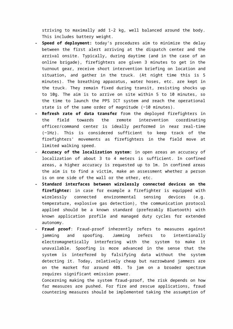
firefighters should ideally be equipped with such a device.
Output environmental explosive gasses
The standalone 3rd party environmental explosive gas detector should output a flag whether explosive gasses have been detected via standardized interfacing protocol with known application profile (wireless e.g. Bluetooth).
Update rate should be near real-time, ideally through synchronized communication with optimized duty cycles.
PPS Self-assessment
S15 and PPS safety assessment intelligence I4
Run self-diagnostics
Upon demand of the user, the PPS shall be capable of running self-diagnostics to simulate, verify correct functioning of all functional modules.
Download self-diagnostics data and report
The user shall be capable of downloading from the PPS the last self-diagnostics data and transform it into a report
Input last full check-up timing
The user shall be capable of inputting the date and time of last full check-up and store it in the PPS.
Generate maintenance (re-calibration) or repair alerts
The PPS shall be capable of generating maintenance or repair alerts, based on e.g. time since last maintenance check-up, time used in interventions, time used in extreme conditions, or even background diagnostics checks, etc.
Generate power low alerts
The PPS shall be capable of flagging low power alert.
Provide basic maintenance instructions
The PPS shall provide the PPS Manager with instructions on basic maintenance procedure to be carried out by the PPS Manager, in line with inspection procedures on breathing apparatus. The inspection procedure shall minimally include easy identification of the PPS (e.g. barcode scanning), an event log with few key dimensions to fill in. This procedure should describe the general inspection methods, but should leave some flexibility w.r.t. performing these tests (as different brigades may use different inspection

approaches).
Include yearly in-depth check-up service
The PPS as a complete solution shall include a servicing component either offered through inspect/repair/replace services or via training and certification programs to do it yourself as PPS Manager.
Sensor interface
I-6
Capture localization parameters
The sensor interface shall include a data capture mechanism interfacing with the localization and positioning system via standardized interfacing protocol with known application profile (in case localization system and local processing device are separate HW devices with wireless or wired interconnection).
Capture physiological monitoring parameters
The sensor interface shall include a data capture mechanism interfacing with a standalone 3rd party physiological monitoring system via standardized interfacing protocol with known application profile (wireless e.g. Bluetooth).
The exchanged data should include following parameters: T skin, T body core, T body core accuracy, heart rate, dehydration level, dehydration level accuracy, and potentially heat stress or skin burn alarm probabilities or flags.
Update rate should be near real-time, ideally through synchronized communication with optimized duty cycles.
Capture environmental temperature measurements
The sensor interface shall include a data capture mechanism interfacing with a standalone 3rd party environmental temperature measurement system via standardized interfacing protocol with known application profile (wireless e.g. Bluetooth).
The exchanged data simply consists of environmental temperature.
Update rate should be near real-time, ideally through synchronized communication with optimized duty cycles.
Capture environmental explosive gasses detection
The sensor interface shall include a data capture mechanism interfacing with a standalone 3rd party environmental explosive gas detector via standardized interfacing protocol with known application profile (wireless e.g. Bluetooth).
The exchanged data simply consists of

environmental explosive gas detection flag.
Update rate should be near real-time, ideally through synchronized communication with optimized duty cycles.
Capture generic data
For modularity and future-proof reasons, the sensor interface shall include one or more data capture mechanisms capable of interfacing with a standalone device via standardized interfacing protocol with known application profile (wireless e.g. Bluetooth).
The exchanged data simply consists of a number of generic data fields of certain format.
Request new sensor data
The sensor interface shall be capable of requesting (polling) the connected sensor devices for updated measurement data.
Auto discover known sensor devices
The sensor interface shall be capable of discover newly plugged or wireless nearby new known sensor devices.
Generate lost connection alert
The sensor interface shall be capable of generating an alert in its communication with the local central processing unit, whenever the connection with one of its interconnected sensor devices (cabled or wireless) is lost.
Intelligent data processing
I-3
(incl. thresholds, alerts
Automatically configure trade-off local vs. remote data processing
The local processing unit shall be capable of assessing whether it should process and interpret captured data locally, or wait for remote instructions and commands.
Take-in/request available sensor data and flags/alerts
The local data processing unit shall be capable of requesting the sensor interface for the most recently available sensor data
Update position data using hypotheses
The local data processing unit shall apply simple rule-based reasoning to filter out non-physical position jumps.

Track individual firefighters
The local data processing shall add the ID of the firefighter to the position data to enable individual named firefighter tracking.
Generate local navigation map
The local data processing shall include a relative ‘track & trace’ map concept.
Generate navigation instructions
The local data processing shall be capable of generating navigation instructions to enable ‘meet point’ and ‘recovery path’ applications on the relative map.
Generate local alerts
The local data processing unit shall include an alert generation mechanism to e.g. generate an ‘explosive gas detected’ alert, ‘heat-stress or skin burn’ alert, ‘flash-over’ danger alert, etc.
Store data - Update local data log
The local processing unit shall be capable of pushing all captured data, all data on activities, decisions, events, etc. to the local data log, enriched with firefighter id, timestamp, etc.
Preprocessing data for local storage
The local processing unit shall aim at efficiently storing the captured data, and hence may apply data preprocessing functions.
Retrieve data from local data log
The local processing unit shall be capable of operating on the local data store and extracting particular types of data, either for internal calculations, either for transfer to the communication module for relay towards the intervention coordinating officer.
Take-in received data from the communication module
The local data processing unit shall include a function to take-in received data from the communication module.
Interpret received data messages through the communication module
The local data processing unit shall include a data message interpretation function that transfers the received data in commands for logging, provide feedback, generate alerts, etc.
Receive communication related alerts
The local data processing unit shall be capable of receiving and interpreting communication related alerts.
Receive power related alerts
The local data processing unit shall be capable of receiving and interpreting power related alerts.

Data log I5 Store data locally
The local data log shall be used to support all functions. It shall contain details of any data captured, any decision that has been taken, all actions that have been taken, events that have occurred, etc.
Manage data log read/write operations
The data log module shall be capable of securing conflictless data log read and write operations.
Manage storage memory overflow
If necessary, the data log module shall be capable of managing storage memory by using techniques as data compression (archiving), deleting older, centrally backed-up data,…
Intuitive user feedback system for the Firefighter I1
Provide multimodal feedback
The user-feedback system shall be multimodal, complementing following modalities: audio (e.g. computer voice generated messages), simple/basic UI (e.g. lights, buttons). At all times ergonomic use should be safeguarded.
Ideally, the audio feedback modality is integrated with the tactical radio device of the Firefighter.
Select modality automatically
The user-feedback system shall incorporate an automated modality selection mechanism, to predict an intuitive combination of modalities or to switch between modalities.
Provide minimal info/feedback
The user-feedback system shall provide minimal information to the firefighter to be aware of his situation, but with limited distraction during interventions.
The user-feedback system shall provide a subset of following (non-exhaustive) information to the firefighter at the right time:
system on/off
(sub-)system error
info: target position reached ("meet point")
alarm: temperature/flash over, get out
alarm: explosive gasses, get out

alarm: heat stress/skin burn, get out
info: get out recovery path instructions
info: nearby colleagues detected
alert: nearby colleague down
info: lost connection to rest of team
info: low power
etc.
Control system for the Firefighter during interventions – I2
Simple switch-on, switch-off
The control system shall enable simple switch-on, switch-off the whole system by the Firefighters themselves (regardless of integrated cabling, wireless interconnections between multiple devices).
Other simple controls
The control system may incorporate few additional control functions, in line with existing approaches such as ‘push-to-talk button’, ‘panic button’.
Capture user inputs
The control system shall capture user input and translate into system commands.

Firefighter communication relay – R10
Determine trade-off message size vs. available bandwidth
Depending on signal strength, emission power, etc. the firefighter’s communication module shall be capable of determining the transmittable/receivable length of data messages.
Determine priority data types to transmit
The communication module shall be capable of selecting for each communication moment the priority data sources (e.g. location coordinates) to transmit to the intervention coordinating officer, given the available bandwidth, the situation at hand, any data requests received.
Extract data from local data log
The communication module shall be capable of extracting the right data from the local data log.
Preprocess data for transmission efficiency
Given the multitude on sensors and functional devices within the firefighter’s PPS, preprocessing of this data and structuring into an efficient data transfer format shall be incorporated as a function of the firefighter’s communication module (e.g. via command look-up tables).
Transmit data The communication module shall be capable of transmitting the preprocessed data, either in broadcast mode, either in an on-demand mode.
Route incoming messages
Throughout the communication architecture, each firefighter’s communication module acts as a node/switch or relay capable of routing incoming messages to the final destination(s).
Receive and unfold data messages
The communication module shall be capable of receiving and unfolding preprocessed data messages.
Make received data available for interpretation
The communication module shall be capable of pushing the received data to the local processing unit or alternatively making the received data available for interpretation capture by the local processing unit.
Generate alert ‘low signal strength, lost signal’
The communication module shall be capable of flagging ‘low signal strength’, ‘lost signal’ alerts.

Intervention Coordinating Officer communication relay – R10
Determine trade-off message size vs. available bandwidth
Depending on signal strengths, emission power, etc. the intervention coordinating officer’s communication module shall be capable of determining the transmittable/receivable length of data messages.
Determine priority data types to receive
The communication module shall be capable of requesting certain data types to the complete network or to individually deployed firefighters.
Request priority data
The communication module shall be capable of requesting certain data types to the complete network or to individually deployed firefighters.
Receive and unfold data messages
The communication module shall be capable of receiving and unfolding preprocessed data messages.
Preprocess data for transmission efficiency
Preprocessing data and structuring into an efficient data transfer format shall be incorporated as a function of the communication module (e.g. via command look-up tables).
Transmit data The communication module shall be capable of transmitting the preprocessed data, either in broadcast mode, either in an on-demand mode.
Determine network update frequency
Taking into account the current network performance in terms of available data rate, signal strengths, etc. the communication module of the intervention coordinating officer shall be able to determine the optimal update frequency (and communicates this to the different deployed firefighters).
Alternatively, the update frequency can also be manually determined by the intervention coordinating officer. In this case the communication module should be capable of setting and communicating this target update frequency.
Generate alert ‘low signal strength, lost signal’
The communication module shall be capable of flagging ‘low signal strength’, ‘lost signal’ alerts.
Intuitive visualization
Display The visualization system shall consist of a display as primary feedback modality (e.g. ruggedized
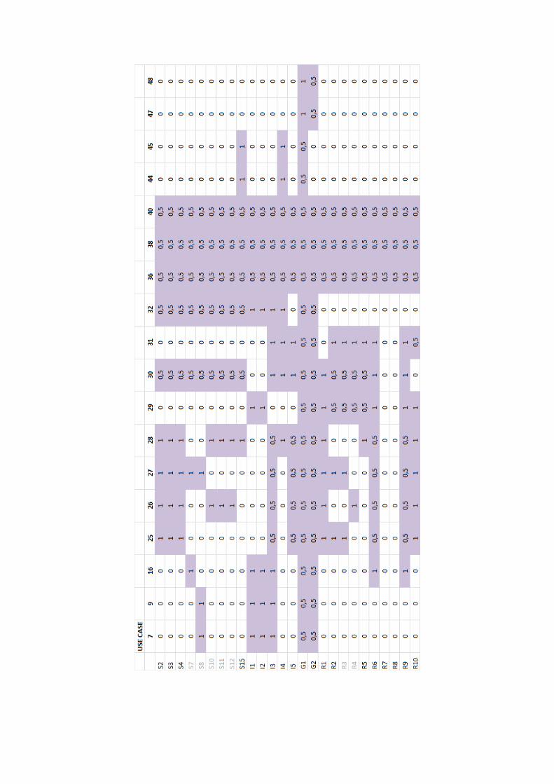
for the intervention coordinating officer – R1
laptop, tablet computer, etc.) to remain as operational as possible when relocating in the intervention area.
Set hierarchical officer level
The visualization system shall be capable of visualizing the intervention situation at multiple hierarchical levels, depending on the role of the intervention coordinating officer during the intervention.
Set target network update frequency
The visualization system shall be capable of setting the required/desired network/data update frequency.
Import Cartesian coordinated map
In case a Cartesian coordinated map is available (e.g. Google maps satellite view of the area), the intervention coordinating officer shall be capable of importing this map and shall use it as overlay on the intervention coordinator’s intuitive map for better situational awareness.
Visualize intervention situation
The visualization system shall be capable of a number of capabilities, in line with intervention coordination procedures and decision/action triggers of the intervention coordinating officers who operate at multiple hierarchical levels (non-exhaustive list):
- Displaying relative 2D/3D track & trace map
- Tracking of individual firefighters- Displaying their status, depending on which
measurement devices the firefighter at hand is equipped with (e.g. physiological parameters, environmental parameters, etc.)
- Displaying the accuracy of their location- Displaying their signal strength- Displaying any received alerts- Displaying any transmitted messages- Recommended alerts (automatically
generated)
Action module to send alerts, messages,…
The visualization system shall include an action module from where the intervention coordinating officers can launch actions, messages, alerts towards the deployed firefighters or intervention coordinating officers operating at a lower level.
Action module to send
The visualization system shall include an action module from where the intervention coordinating

navigation instructions
officers can launch navigation instructions towards the deployed firefighters (or intervention coordinating officers operating at a lower level).
Additional data configuration function
In case additional data sources have been coupled locally (see also function ‘generic data capture’), the visualization system shall include a configuration module to allow interpretation of these data sources into meaningful info and related thresholds might be set accordingly.
Provide module to escalate alerts
The visualization system shall include a module from where generated alert escalation can be configured (e.g. automatic/manual escalation to identified higher levels of hierarchical coordination) and actual escalations can be performed.
Provide module to accept/refuse, configure aggregated intervention data
The visualization system shall include a module to configure data aggregation settings, to accept/refuse/automate aggregation of intervention data.
Central terminal processing unit – R6
Automatically configure initial trade-off local vs. remote data processing
The central processing unit shall be capable of determining the initial configuration of local vs. central data processing.
Push local vs. remote data processing configuration
The central processing unit shall initiate communication of the configuration to the deployed local firefighters.
Capture and interpret aggregated data
The central processing unit shall be capable of integrating captured aggregated data from other intervention coordinating officer.
Generate automatic alert recommendations
The central data processing unit shall include an alert generation mechanism to e.g. generate an ‘explosive gas detected’ alert, ‘heat-stress or skin burn’ alert, ‘flash-over’ danger alert, time-in-intervention alert etc. and translate these triggers in recommended alerts for the intervention coordinating officer to decide upon.
Update position data using hypotheses
The central data processing unit shall apply simple rule-based reasoning to filter out non-physical position jumps from individual

firefighters and between firefighters.
Track individual firefighters
The central data processing will keep the ID of the firefighter linked to the received position data
Generate overall navigation map
The central data processing shall build and keep up-to-date a relative ‘track & trace’ map of the known intervention situation.
Generate individual navigation instructions
The central data processing shall be capable of generating navigation instructions to enable ‘meet point’ and ‘recovery path’ applications for individual firefighters on the relative map.
Store data - Update central data log
The central processing unit is capable of pushing all captured data, all data on activities, decisions, events, etc. to the central data log, enriched with firefighter id, timestamp, etc.
Preprocessing data for central storage
The central processing unit aims at efficiently storing the captured data, and hence may apply data preprocessing functions.
Retrieve data from central data log
The central processing unit is capable of operating on the central data store and extracting particular types of data, either for internal calculations, either for transfer to the communication module for relay towards the deployed firefighters.
Interpret received data messages through the communication module
The central data processing unit shall include a data message interpretation function that interprets received data and triggers logging, alert generation, etc.
Receive communication related alerts
The central data processing unit shall be capable of receiving and interpreting communication related alerts.
Receive power related alerts
The local data processing unit shall be capable of receiving and interpreting power related alerts (both from own communication module as received from the communication module as message from one of the firefighters.
Send out escalations
Whenever the intervention coordinating officer triggers the escalation of an alert or message via the escalation module on the visualization system.
Treat incoming escalations
The central processing unit shall be capable of translating incoming escalations received from the escalation gateway to ‘escalated

alerts/messages’.
Central data log R2, R3, R4, R5
Store data locally
The central data store shall be used to support all functions. It shall contains details of any data captured, any decision that has been taken, all actions that have been taken, events that have occurred, etc. across all deployed firefighters and intervention coordinating officers.
The central data storage may be performed on the technological equipment of the intervention coordinating officer, on existing infrastructure of the firefighter truck, on additional infrastructure to be added on the firefighter truck, in a virtual datacenter connected to the firefighter truck, or yet another configuration.
The chosen set-up shall however focus on aligning with existing available infrastructure, hence minimally adding extra infrastructure. (see also high-level functional requirements).
Manage data log read/write operations
The data log module shall be capable of securing conflictless data log read and write operations.
Manage storage memory overflow
If necessary, the data log module shall be capable of managing storage memory by using techniques as data compression (archiving), or deleting older data
Escalation gateway – R7
Escalate alerts The intervention coordination system shall be capable of automatically or manually escalate alerts generated at the scene towards higher hierarchically-ranked responsible intervention officers.
The central terminal shall therefore be equipped with an escalation gateway applying a known interfacing protocol, and ideally using existing available infrastructure
Capture incoming escalated alerts
In certain situations it may be required for the intervention coordinating officer to include in his assessment of the situation, incoming escalated alerts from other crews or higher officers.
To this end the escalation gateway shall be capable of capturing incoming escalations and transfer these to the central processing unit of the
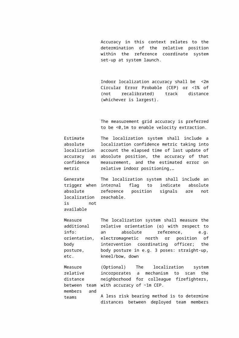
intervention coordinating officer.
Data aggregation subsystem- R8
Aggregation of intervention data
Given the hierarchical constellation in which firefighter intervention are carried out (L1: 1 intervention coordinating officer per 2 or 3 binomes; L2: 1 intervention coordinating officer coordinating 4 L1 intervention coordinating officers, etc.), the PPS system shall allow for aggregation of intervention data at multiple hierarchical levels.
The data aggregation may be performed on the technological equipment of the intervention coordinating officer, on existing infrastructure of the firefighter truck, on additional infrastructure to be added on the firefighter truck, in a virtual datacenter connected to the firefighter truck, or yet another configuration.
The chosen set-up shall however focus on aligning with existing available infrastructure, hence minimally adding extra infrastructure. (see also high-level functional requirements).
Local PPS device(s) on firefighter - G1 (integration)
PPE turnout gear: integration with textile and ICT systems
Integration between the Smart PPS technological ICT equipment and standard PPE turnout gear shall be kept to limited integrative measures such as well-designed pockets, inner-shell cabling textile tubes, inner-shell velcro strips, inner-shell belts, inner-shell slip knots, etc.
Outer-shell integration of ICT components with the turnout gear shall be left out of the PPS design as manufacturing cost, robustness issues, etc. cannot be solved today within the envisaged go-to-market timeframe.
Mechanical design, housing, electronic HW
The mechanical housing and HW electronics design shall be robust and shall include electromagnetic shielding (e.g. for sensors, microcontrollers,…) without implementing military grade measures.
Cabling and connectors
In case cabling is applied, cabling shall cover only inner-shell cabling and specifically designed to:
minimize impact on ergonomics cope with different standard sizes of
turnout gears easy and fast mounting and dismounting
(e.g. for repair/replace) if designed in and left in during cleaning

operations: robust and durable to meet the lifetime prescriptions
The cabling (if applied) shall be of electromagnetic shielded type.
Retrofitting cabling into existing installed base of turnout gear should not be considered a feasible option.
Wireless Body Area Network (BAN)
In case the PPS solution includes wireless interconnections between multiple devices on the firefighter, this Body Area Network shall include measures to cope with the risk of interference. Tests need to be performed to make sure that the frequency spectrum is optimally used, balancing communication between e.g. sensor devices (body and environment) on the firefighter’s, localization system and radio communication towards the remote intervention coordinating terminal.
Batteries The dimensioning of the battery type and capacity shall take into account the autonomy requirements as stipulated in section 3 High-level functional requirements.
Recharging multiple PPS batteries in parallel at the PPS maintenance center shall be included in the design of the PPS solution.
Weight The PPS shall add maximally 2-3 kg to the total firefighter gear, including batteries.
The weight shall be well balanced on the firefighter’s body, minimally impacting

Appendix 11: Award criteria (detailed description)
[Explanation: a detailed description of the award criteria can be found below. The award criteria with regard to turnout gear are not described in this template as they were not part of the Smart@Fire scope. The Contracting Authority can fill in these requirements as was done for the past purchases.]
Criteria 1 - Turnout Gear Quality - X Points
a. Tensile strengthb. Tear strengthc. Flame Heat HTI 24d. Flame Heat HTI 24-2e. Radiant Heat RHTI 24f. Radiant Heat RHTI 24-12g. Water vapor permeability RETh. Delivery time backorder turnout gear
Criteria 2 - Turnout Gear User Experience - X Points
a. Static testb. In & around vehiclec. Warm test ‘flashover container’d. Warm test ‘attack container’e. Periodic preventive medical examination + crawl/obstacle circuit
Criteria 3 – PPS Performance – X Points
a. Localization- In open areas an accuracy of localization of about 3 to 4 meters is sufficient. - In confined areas, a higher accuracy is requested: <2m and <1% of inertial
track distance (whichever is largest) In confined areas the aim is to find a victim, make a correct assessment whether a person is on one side of the wall or the other, etc (During PPS prototype testing, it appeared to be difficult, but might be possible if map is available. Unfortunately, not all buildings have a digital map available).
- In case inertial or alike localization technologies are used, measurements should be updated at least at a 10cm interval or less.
- Once deployed the localization devices shall become operational seamlessly (Should be self-calibrating, self-referencing, time-synchronisation).
- Measure absolute (outdoor) position data.- Measure relative (indoor) position data.- Estimate absolute localisation accuracy.- Generate trigger when absolute localisation is not available.- Measure additional info: Orientation, body posture in e.g. 3 poses: straight-
up, kneel/bow, down.- Measure relative distance between team members and team with accuracy
of ~1m CEP.

b. Output location data- The output data shall contain:
o Absolute 3D position and 2D orientation. o Measurement confidence metric.o Relative distance towards other team members (if locally
determined). o Any additional measured parameters body posture, etc..o The output mode of operation shall be either broadcast (push, with
optimized/synchronized duty cycles) or on request (pull).
c. Signal Reach- Signal P2P / 120m reach.d. Refresh Rate- Refresh rate of data transfer from the deployed firefighters in the field
towards the remote intervention coordinating officer/command center is ideally performed in near real-time (~1Hz).
e. Data Aggregation- Scalability of the system (Max 18 FF per ICO - Min. 6-8 FF).- Given the hierarchical constellation in which firefighter intervention are
carried out (L1: 1 intervention coordinating officer per 2 or 3 binomes; L2: 1 intervention coordinating officer coordinating 4 L1 intervention coordinating officers,etc.), the PPS system shall allow for aggregation of intervention data at multiple hierarchical levels.
f. Indoor drift- Limited indoor drift: <1% of inertial track distance or <2m whichever is
largest.
g. Autonomy- The minimally required autonomy for the PPS system is about 2 hours when
all functionalities are operational, and up to 4 hours in a forest fire configuration.
Criteria 4. PPS System - X Points
a. Configurations- The system architecture should allow for flexible operation and
configuration. 4 main configurations can be distinguished:o Basic configuration: localization + remote connectivity + intuitive
visualization.o Physio configuration: localization + remote connectivity + intuitive
visualization + physiological monitoring.o Urban configuration: localization + remote connectivity + intuitive
visualization + environmental monitoring.o Full functional configuration: localization + remote connectivity +
intuitive visualization + physiological monitoring + environmental monitoring.
b. Interfaces with sensors

- Standard interfaces between wirelessly connected devices on the firefighter.- Capture localisation parameters.- Capture physiological monitoring parameters. And sco- Capture environmental temperature measurements.- Capture environmental explosive gasses detection.- Capture generic data.- The sensor interface shall be capable of requesting (polling) the connected
sensor devices for updated measurement data.- The sensor interface shall be capable of discover newly plugged or wireless
nearby new known sensor devices.- Generate lost connection alert.- Capture Equipment Status.
c. PPS Self-Assessment- Run self-diagnostics- Download self-diagnostics data and report- Input last full check-up timing- Generate maintenance (re-calibration) or repair alerts- Generate power low alerts- Provide basic maintenance instructions- Include yearly in-depth check-up service
h. What if- System failure? Back-up?.i. Limited integration with textiles- Total duration of replacing the cabling designed in into the layers of the
turnout gear can maximally take 15 minutes.- A PPS maintenance responsible can easily carry out the replacement task,
without specialized help of a textile specialist.- Integration between the Smart PPS technological ICT equipment and
standard PPE turnout gear shall be kept to limited integrative measures such as well-designed pockets, inner-shell cabling textile tubes, inner-shell velcro strips, inner-shell belts, inner-shell slip knots, etc.
Criteria 5. - PPS User Experience - X Points
a. Intervention coordinating officero An Intervention coordinating officer should be able to:
o consult a 'relative' map to locate the FF teams.o consult a relative map to locate the FF teams enriched with env.
Temperature and Temperature evolution.o consult a relative map to locate the FF teams enriched with Physical
Health parameters.o consulting a relative map to locate the FF teams enriched with
equipment status.o use an intuitive visual system and semi-automated data
interpretation (e.g. for outlier handling).o inform the FF by generating an alert (Using the available data).o escalate alerts / available data to create an aggregated view.
b. Fire Fighter

o A Fire Fighter should be able to use:o An intuitive feedback system to not distract his operations.o Measure environmental parameters (Temperature, Temperature
Evolution, explosive gasses).o Relying on self-assessment of available, coupled sensors, devices.
c. Department Head- A department head should be able to :
o Use historical logging of available data for RCA, audit trails… .
d. Trainer- A trainer should be able to:
o Use similar remote monitoring available info to improve trainees
Criteria 6. - PPS Mechanics - X Points
a. Battery life time- The minimally required Battery Life Time for the PPS system is about 2 hours
when all functionalities are operational, and up to 4 hours in a forest fire configuration.
b. Battery charging- Recharging multiple PPS batteries in parallel at the PPS maintenance center
shall be included in the design of the PPS solution.
c. Weight & Weight Balancing- The PPS should be kept as lightweight as possible striving to maximally add
1-2 kg, well balanced around the body. This includes battery weight.
d. CablingIn case of cabling is applied, cabling should only cover inner-shell cabling and
specifically designed to: o Minimize impact on ergonomics o Cope with different standard sizes of turnout gear (e.g. repair / replace) o Electromagnetic shielded type
e. Certainty of supply- Electronic architecture: selection of components for e.g. repair should be
open to different suppliers (avoid supplier lock-in)
f. Compatibility- PPS should be compatible with different PPS’s to avoid supplier lock in.
Criteria 7 - PPS Environmental Robustness – X Points
a. Standardization / Safety- Standardization and guaranteeing safety:
o At all times the PPS should fulfill basic health and safety requirements. For the PPE turnout gear, health and safety requirements are safeguarded through existing directives (in

particular Directive 89/686/EEC on Personal Protective Equipment, covering among other the liability of the product manufacturers and Directive 89/656/EEC on the use of personal protective equipment, covering among other the obligations of the employers). These directives also apply to PPE containing ICT solutions (smart textiles), into which e.g., ICT cables, sensors and actuators are integrated within the PPE textile. Manufacturers are obliged to demonstrate that their products are conform to these EU laws. This can be done for example by testing and evaluating according to harmonized standards, including EN 469:2005 for the fire fighters suit.
b. EU Legislation IT / Electronics- EU legislation regarding ICT and electronics:
o On the other hand, suppliers will also need to comply with the EU legislation regarding ICT and electronics, including application in fire and rescue situations, requiring CE or other marking (e.g. EX marking for applications in potentially explosive atmospheres). , These include ), Directive 1999/5/EC on radio equipment and telecommunications terminal equipment and the mutual recognition of their conformity (RTTE), material related legislation, including Regulation 1907/2006/EC concerning the Registration, Evaluation, Authorization and Restriction of Chemicals(REACH) and Directive 2002/95/EC on the restriction of the use of hazardous substances in electrical and electronic equipment (RoHS). For EX marking Directive 94/9/EC on equipment and protective systems intended for use in potentially explosive atmospheres (ATEX) is applicable.
Criteria 8. - PPS Operational Fit - X Points
a. Fraud Proof- Fraud-proof inherently refers to measures against jamming and spoofing.
Jamming refers to intentionally electromagnetically interfering with the system to make it unavailable. Spoofing is more advanced in the sense that the system is interfered by falsifying data without the system detecting it. Today, relatively cheap but narrowband jammers are on the market for around 40$. To jam on a broader spectrum requires significant emission power.
- Concerning making the system fraud-proof, the risk depends on how far measures are pushed. For fire and rescue applications, fraud countering measures should be implemented taking the assumption of normal civil environments. Military-grade measures are considered out of scope for this project.
b. Interference measures- limiting interference (cfr. data connectivity)- Electromagnetic shielding of the different devices (sensors, processing unit,
…), without implementing military-grade measures.
c. Robustness- Robustness under washing and exposure to specific substances (in case the
PPS holds functional building blocks which are exposed to the hazardous

environment)o washing procedures: <details of washing procedure and expected
results>o exposure to chemicals, toxic gasses, etc.: <details of test
procedure and expected results>
d. Additional infrastructure- The PPS should work with minimal additional needed infrastructure: e.g.
data aggregation servers, extra communication antennas, etc. on the firefighter trucks.
e. Launch Time- Easy launch, start-up and assurance of correct operations via minimal # Uis
(5 to 10 minutes)
Criteria 9. - Financial offer - Total Cost of ownership (TCO) - X Points
Points awarded = (price lowest tenderer / price tenderer) * maximum points
Appendix 12: Scoring model
[Explanation: For award criteria 1 and 2 the classic scoring mechanisms are used for buying turnout gear. Possible scoring models for criteria 3 to 9 can be found below.]
1. Turnout Gear Quality
Scoring Guide
1 [=]
2 [=]
4 [=]
6 [=]
8 [=]
10 [=]
[=]
2. Turnout Gear User Experience
Scoring Guide
1 [=]
2 [=]

4 [=]
6 [=]
8 [=]
10 [=]
[=]
3. The extent of how well the proposed product meets the challenge with regard to the PPS performance
Scoring Guide
1 There is no indication that the tender will meet the challenge.
2 There is very little indication that the tender is likely to meet the challenge.
4 There is little indication that the tender is likely to meet the challenge.
6 There is some indication that the tender is likely to meet the challenge.
8 There is indication that the tender will meet the challenge.
10 There is clear indication that the tender will meet the challenge.
The tenders response to this criteria is out of scope, give the minimum score of 1
4. The extent of how well the proposed product meets the challenge with regard to the PPS system
Scoring Guide
1 There is no indication that the tender will meet the challenge.
2 There is very little indication that the tender is likely to meet the challenge.
4 There is little indication that the tender is likely to meet the challenge.
6 There is some indication that the tender is likely to meet the challenge.
8 There is indication that the tender will meet the challenge.
10 There is clear indication that the tender will meet the challenge.
The tenders response to this criteria is out of scope, give the minimum score of 1
5. The extent of how well the proposed product meets the challenge with regard to the PPS User Experience

Scoring Guide
1 There is no indication that the tender will meet the challenge.
2 There is very little indication that the tender is likely to meet the challenge.
4 There is little indication that the tender is likely to meet the challenge.
6 There is some indication that the tender is likely to meet the challenge.
8 There is indication that the tender will meet the challenge.
10 There is clear indication that the tender will meet the challenge.
The tenders response to this criteria is out of scope, give the minimum score of 1
6. The extent of how well the proposed product meets the challenge with regard to the PPS Mechanics
Scoring Guide
1 There is no indication that the tender will meet the challenge.
2 There is very little indication that the tender is likely to meet the challenge.
4 There is little indication that the tender is likely to meet the challenge.
6 There is some indication that the tender is likely to meet the challenge.
8 There is indication that the tender will meet the challenge.
10 There is clear indication that the tender will meet the challenge.
The tenders response to this criteria is out of scope, give the minimum score of 1
7. The extent of how well the proposed product meets the challenge with regard to the PPS Environmental robustness
Scoring Guide
1 There is no indication that the tender will meet the challenge.
2 There is very little indication that the tender is likely to meet the challenge.
4 There is little indication that the tender is likely to meet the challenge.
6 There is some indication that the tender is likely to meet the challenge.
8 There is indication that the tender will meet the challenge.

10 There is clear indication that the tender will meet the challenge.
The tenders response to this criteria is out of scope, give the minimum score of 1
8. The extent of how well the proposed product meets the challenge with regard to the PPS Operational Fit.
Scoring Guide
1 There is no indication that the tender will meet the challenge.
2 There is very little indication that the tender is likely to meet the challenge.
4 There is little indication that the tender is likely to meet the challenge.
6 There is some indication that the tender is likely to meet the challenge.
8 There is indication that the tender will meet the challenge.
10 There is clear indication that the tender will meet the challenge.
The tenders response to this criteria is out of scope, give the minimum score of 1
IX Pricing - Total cost of ownership
Points awarded = ( 1 - (tender price / maximum price) )* maximum points

Appendix 13 Tender Form (Technical and Financial offer)
Max total amount of pages […] (tenderers should print on A4 max. X pages). If the tender exceeds the page limit then all words and / or pages in excess of
the specified limit will not be considered further. For consortiums, this tender form should be signed by each of the consortium
members!
Submitted by:
Reference Number
Date
Question I
Describe the proposed turnout gear
Max X pages A4, font Calibri 11 or equal. Images can be attached separately.

Question II.
Describe the proposed PPS product and how this addresses the tender challenges
Max X pages A4, font Calibri 11 or equal. Images can be attached separately.
Work in 2 sections:
A. Overall overview of the productB. Zoom-in on key technological aspects (the sources of complexity/risk) as listed hereafter
W.r.t. overall system architecture:
- Describe the approach and choices made in setting up the right architecture optimally balancing trade-offs of distributed vs. central processing, local performance vs. remote responsiveness (online vs. offline), scalability/flexibility/modularity of the system, interfaces for escalation and aggregation, etc.
W.r.t. data transfer between firefighters
- Which connectivity architecture is chosen (infrastructure-based PMR, MANET, Point-to-Point,…)?
- Explain the implications of the underlying architecture on indoor penetration performance and data rate (bandwidth)? Which optimization measures are considered for further solution exploration?

- The update rate of logging the network data to the remote intervention coordinating officer should approach near real-time (~1Hz). Elaborate on optimizing the scalability trade-off of deployed network nodes vs. update rate, preprocessing mechanisms of data, etc.
W.r.t. data connectivity on the firefighter’s body:
- Is a cabled or wireless approach envisaged? Which technology/protocol is adopted?
- Which interference counteracting measures are envisaged? Explain their impact on the interference problem.
W.r.t. ICT-textile integration aspects:
- Note: preferentially, limited integration with PPE textile is envisaged, due to both technological and standardization related constraints.
- Note: some integration with the PPE is obliged, due to the nature of the procurement.
- Which integrative measures are taken in the proposed solution/system (e.g. Velcro, pockets, clips, etc.)?
- If a cabled approach is selected: how are easy mounting/replacing of cables/connectors; durability of cables/connectors and dealing with different turnout gear sizes dealt with?

- If a wireless set-up is chosen: which interference measure are undertaken? How can the system be intuitively launched, assuring correct operations via minimal amount of UI’s?
- Which electromagnetic shielding measures are foreseen?
W.r.t. user restitution, visualization
- The intervention coordinating officer should be provided an intuitive UI dashboard, which is aligned with way of working. Describe the approach to safeguard this alignment.
- Which modalities are selected to provide feedback to the firefighter in the field (e.g. audio, simple UI/buttons/lights, haptic belt)?
- How will ergonomic use of the feedback system be ensured?
- How will automatic modality selection be achieved?
W.r.t. localization:
- Which technological type of localization system, hybrid (GPS + inertia), hybrid (GPS + …), beacon-based,… is chosen?
- In case hybrid: how will indoor drift be limited? Please provide an indication of currently achieved performance w.r.t. indoor drift with the proposed hybrid localization system. Shortly describe the experimental set-up.
- In case a beacon-based approach is considered, how is fast deployment assured without losing accuracy? Please also provide insight in estimation of TCO for 1 firefighter brigade. Make assumptions on #interventions, #trucks, #firefighters, …

- Regarding determination of distance between firefighters of the same team, of different teams: is relay over the intervention coordinating officer considered an option? Is it determined directly between firefighters?
- How is the concept of a “MAP” integrated in the proposed solution? Are ‘track & trace’, ‘meet point’ and ‘recovery path’ instructions considered? Can Cartesian coordinated maps be integrated as overlay?
W.r.t. sensors
- Which known standard interfacing protocol and application profile are chosen to interconnect the central nerve system with peripheral wireless devices (e.g. temperature measurement, explosive gas detection)?
- Note that the goal is not to develop new sensors, but merely interface with existing cost-effective solutions.
Question III.
Describe the impact of using the envisaged PPS product on the day-to-day operational processes. are the main benefits for the fire brigade?
Max X pages A4, font Calibri 11 or equal. Images can be attached separately.
Question IV.Describe the envisaged business model.
Max X pages A4, font Calibri 11 or equal. Images can be attached separately.

What will be the preferred business model for the tenderer: one-off capex investment vs. lease and buy-back programs vs. …? Are there any license fees to be paid?
Which options will be available w.r.t. maintenance and service contract? Please elaborate on inspections procedures, on call repair and support, training and certification programs,…

Question V.Describe the standardization and testing approach.
Max 3 pages A4, font Calibri 11 or equal. Images can be attached separately.
Which process, parties involved, recommended certification procedures are adopted?
Describe performed or testing on the PPS. Elaborate on measures taken, tests/experiments performed, certificates issued, etc.
Question VI.Who are the Tenderers? Resources.
Max 4 pages A4, font Calibri 11 or equal. Images can be attached separately.
Specify the configuration (e.g. consortium) and role of each partner (e.g. system integrator). Which

party will take-up the role of prime tenderer?
Describe the profile and expertise of the project manager and project team serving as main point of contact and consultation with the Contracting Authority. Include project staffing details. Also include the expertise of any subcontractors involved in the project, if applicable.
Provide proof of at least 3 relevant similar projects, where innovative systems have been developed in close collaboration with end-users of a customer. Elaborate on scope, approach, timing, total budget, project reference contact, size of the project team, adopted technologies,… In addition, focus on setting up user acceptance testing. Which criteria have been applied?
Which part of the contract you intend to subcontract? Give an overview of the subcontractors you’ll work with in the execution of the Contract and explain why you need a subcontractor?

Question VII.Financial offer – Total Cost of ownership (TCO) cost breakdown
Max 4 pages A4, font Calibri 11 or equal. Images can be attached separately.
1. What is the total (1-off) cost to equip with a fully functional solution of smart PPS. A fully functional solution of smart PSS for X team holds:o Turnout gears, for X firefighterso Technological components loosely attached to the turnout gear, for X firefighterso Equipment for X intervention coordinating officero Any additional equipment: e.g. local mobile antenna’s, antenna’s fixed on the truck, data
aggregation infrastructure on the truck or in the cloud, etc.
2. Include in the price breakdown a detailed overview of the total maintenance cost over a lifecycle of X years. Take realistic assumptions. Explain all assumptions taken.
3. Explain how this cost model will scale of e.g. to equip X teams as described above; to equip X teams as described above.
A complete answer provides the Contracting Authority insight in all 3 questions.
Note: the Contracting Authority are aiming for qualitative solution with minimal TCO