Embed Size (px)
Citation preview
Wired4imagination.comSolve problems in low voltage A.C. circuits
UEENEEG102ADr. Kenneth Meyer
Electrical AC Physics Tutorial Exercises for Students
1Wired4imagination.com
Developed and Owned by Kenneth Meyer
Solve problems in low voltage A.C. circuitsUEENEEG102A
Dr. Kenneth Meyer
Electrical AC Physics Exercises for Students
1. AC Fundamentals
2. Phasor Maths
3. R,L & C in AC circuits
4. RLC in series AC circuits
5. RLC in parallel AC circuits
6. Single phase Power
7. Power Factor Correction & Harmonics
8. Three phase introduction
9. Three phase Star (wye)
10. Three phase Delta (Mesh)
11. Three phase power
12. Earth Fault Loop Impedance
13. Dr Ken’s Assessment Technique tips
May also be used as supplementary evidence as appear of assessment
Students Name: Date:
2Wired4imagination.com
Developed and Owned by Kenneth Meyer

Electrical Trad Principles ( Phillips 3rd ED) Textbook links
1. AC Fundamentals 15.1 -15.4 (page 332)
2. Phasor Maths 15.5 -15.6 (page 346)
3. R,L & C in AC circuits 16.1 -16.7 (page 359)
4. RLC in series AC circuits 17.1 -17.4 (page 378)
5. RLC in parallel AC circuits 18.1 -18.6 (page 401)
6. Single phase Power 19.1 -19.3 (page 419)
7. Power Factor Correction & Harmonics 19.4 -19.5 (page 419)
8. Three phase introduction 20.1 -20.2 (page 436)
9. Three phase Star (wye) 20.3 & 20.5 (page 440)
10. Three phase Delta (Mesh) 20.4 (page 444)
11. Three phase power 20.6-20.7 (page 444)
12. Earth Fault Loop Impedance
13. Dr. Ken’s Assessment techniques
3Wired4imagination.com
Developed and Owned by Kenneth Meyer
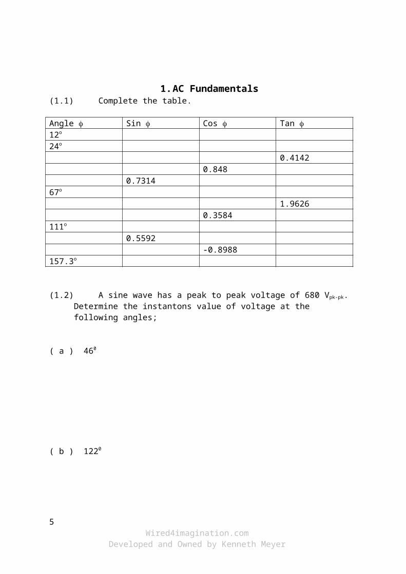
1. AC Fundamentals(1.1) Complete the table.
Angle Sin Cos Tan 12o
24o
0.41420.848
0.731467o
1.96260.3584
111o
0.5592-0.8988
157.3o
(1.2) A sine wave has a peak to peak voltage of 680 Vpk-pk. Determine the instantons value of voltage at the following angles;
( a ) 460
( b ) 1220
( c ) 2720
4Wired4imagination.com
Developed and Owned by Kenneth Meyer
(1.3) A sine wave has a maximum current of 50 amps at a frequency of 50 Hz. Determine the instantaneous value of current after the following times;
( a ) 7ms
( b ) 10ms
( c ) 17ms
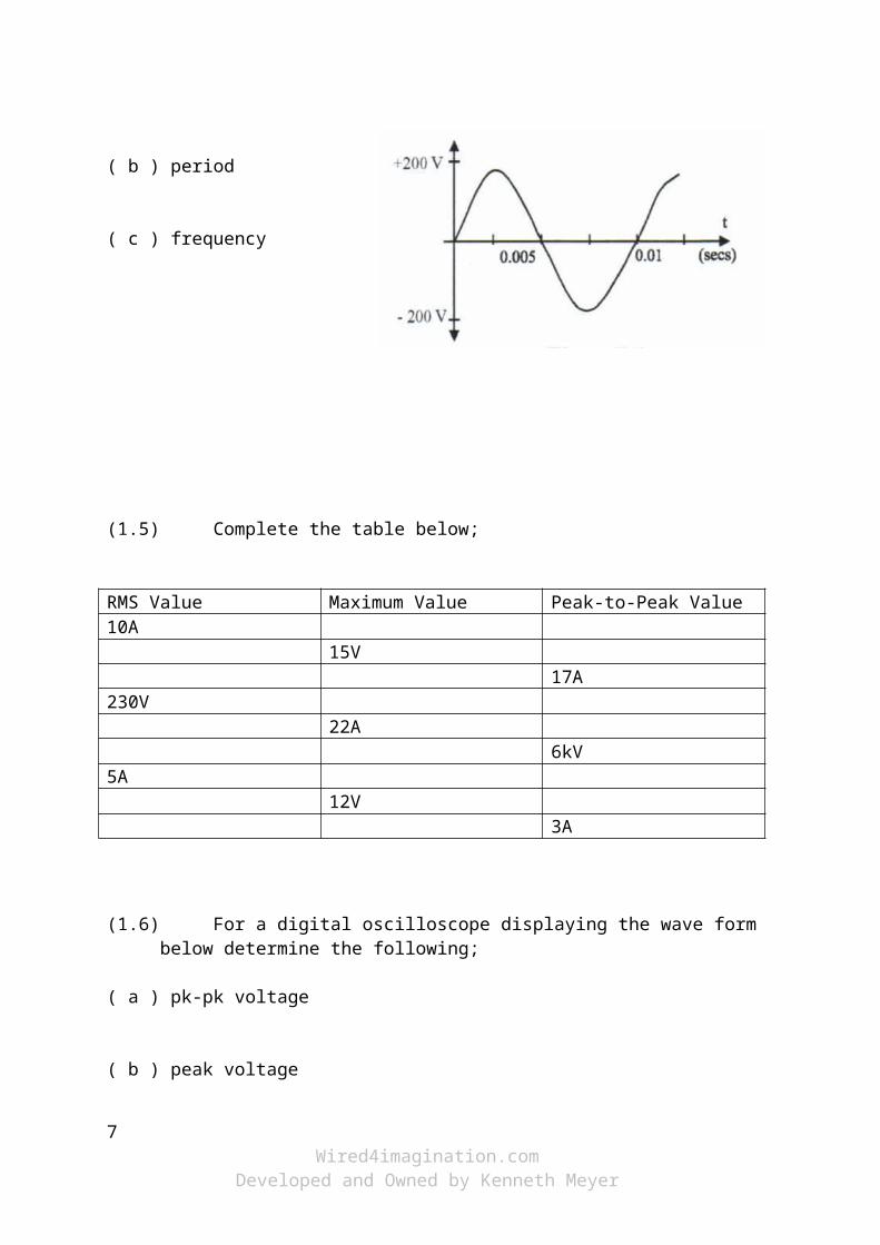
(1.4) For the wave form below determine the following
( a ) peak-to-peak voltage
( b ) period
( c ) frequency
5Wired4imagination.com
Developed and Owned by Kenneth Meyer
(1.5) Complete the table below;
RMS Value Maximum Value Peak-to-Peak Value10A
15V17A
230V22A
6kV5A
12V3A
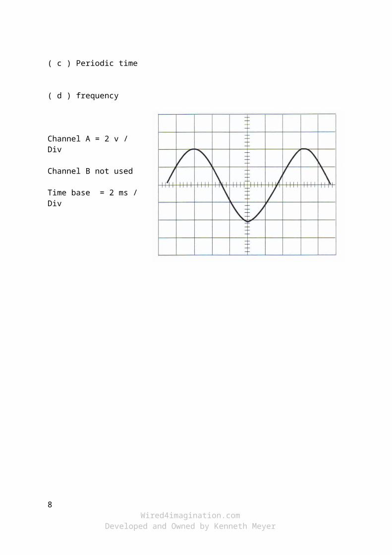
(1.6) For a digital oscilloscope displaying the wave form below determine the following;
( a ) pk-pk voltage
( b ) peak voltage
( c ) Periodic time
( d ) frequency
Channel A = 2 v / Div
Channel B not used
Time base = 2 ms / Div
6Wired4imagination.com
Developed and Owned by Kenneth Meyer
2. Phasor Maths
(2.1) Draw a phasor diagram to show a voltage of 220v lagging the reference by 300 and a voltage of 255v lagging the reference by 150. (Indicate the DOR).
7Wired4imagination.com
Developed and Owned by Kenneth Meyer
(2.2) (a) What is the addition of two currents of 12A < -450 and 17 A < -250.
(b) What is the phase angle between the result and the reference?
8Wired4imagination.com
Developed and Owned by Kenneth Meyer
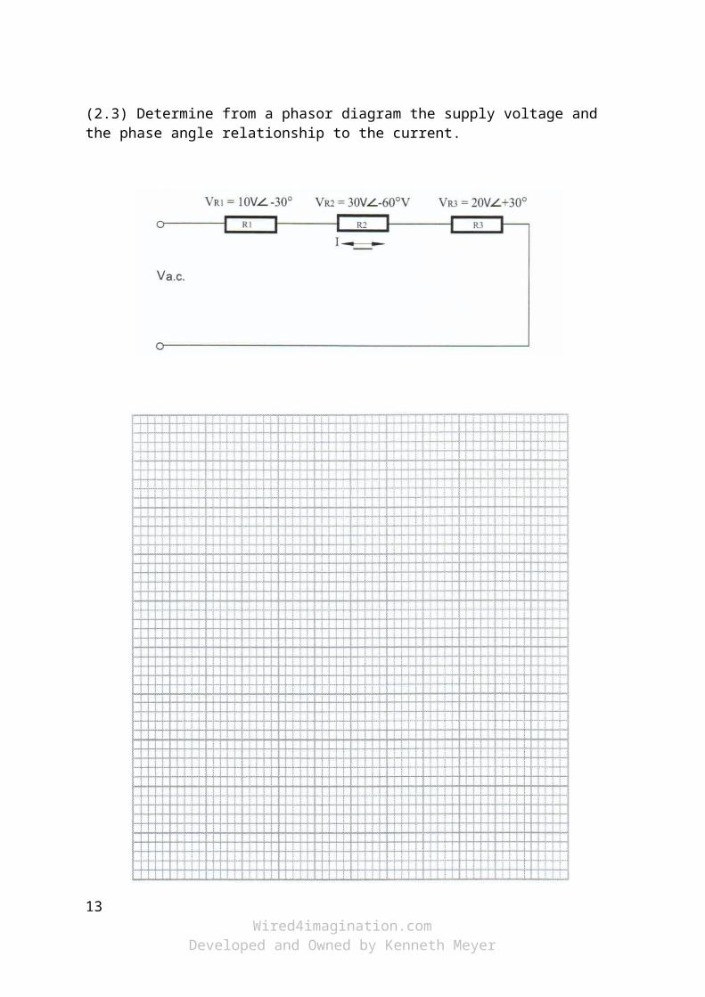
(2.3) Determine from a phasor diagram the supply voltage and the phase angle relationship to the current.
9Wired4imagination.com
Developed and Owned by Kenneth Meyer

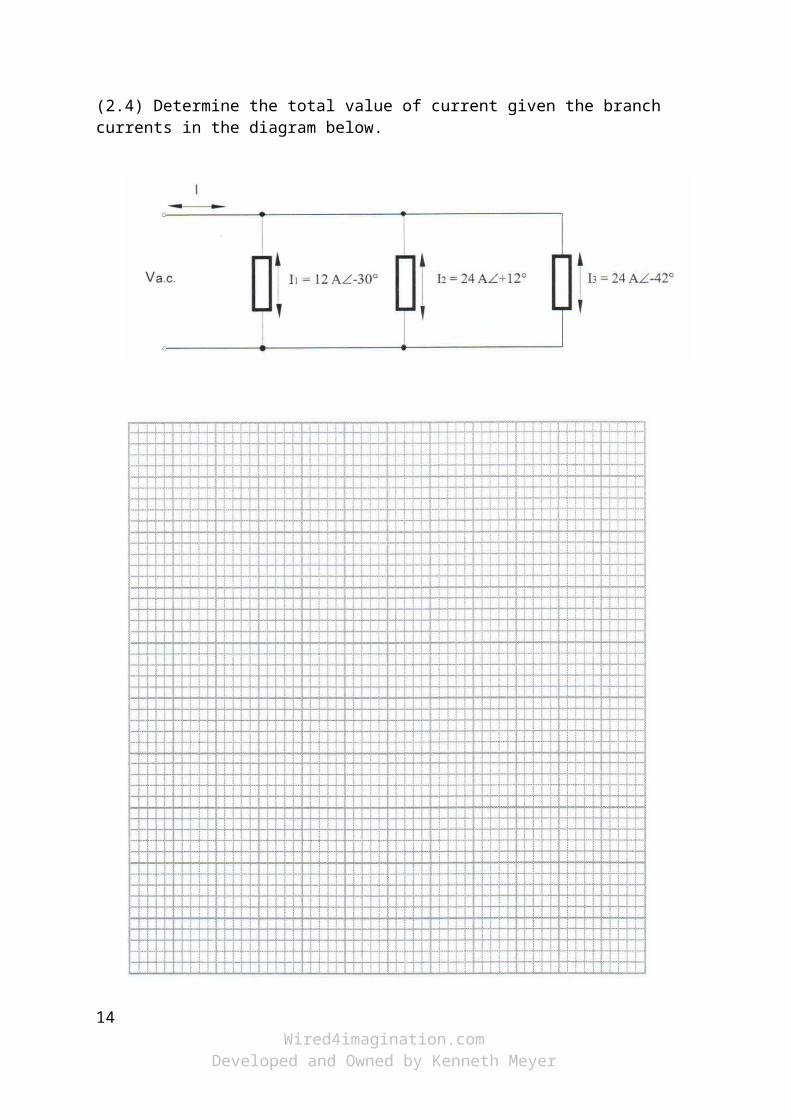
(2.4) Determine the total value of current given the branch currents in the diagram below.
10Wired4imagination.com
Developed and Owned by Kenneth Meyer
Blank
11Wired4imagination.com
Developed and Owned by Kenneth Meyer

3. R,L & C in AC circuits
(3.1) A purely resistive lamp is connected to a 32v, 50 Hz supply. The lamp draws a current of 2.2 amps. Determine ;
(a) Circuit resistance
(b) Circuit impedance
(c ) Power consumed by the circuit
(3.2) A 2.7 k resistor is connected to a variable frequency source. If the frequency is 2 kHz and the circuit current is 4mA, determine the voltage of the supply.
(3.3) A heater draws a current of 10 amps and has a resistance of 22; Determine;
(a) The applied voltage
(b) The circuit impedance
( c) Power supplied by the heater
12Wired4imagination.com
Developed and Owned by Kenneth Meyer
(3.4) An ideal inductor draws a current of 12 Amps when connected to 220v, 60 Hz. Determine the current if the same circuit is connected to 120v, 100 Hz,
(3.5) Calculate the capacitance of a motor start capacitor if its capacitive reactance is 110 Ohms at 50 Hz.
(3.6) Determine the current taken by a 110 F capacitor when it is connected to 240v, 60 Hz supply for the purpose of power factor correction.
13Wired4imagination.com
Developed and Owned by Kenneth Meyer
Blank
14Wired4imagination.com
Developed and Owned by Kenneth Meyer
4. RLC in series AC circuits
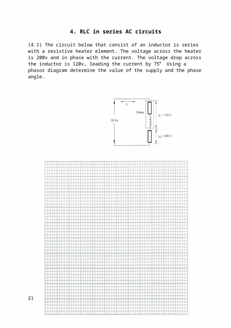
(4.1) The circuit below that consist of an inductor is series with a resistive heater element. The voltage across the heater is 200v and in phase with the current. The voltage drop across the inductor is 120v, leading the current by 750 Using a phasor diagram determine the value of the supply and the phase angle.
15Wired4imagination.com
Developed and Owned by Kenneth Meyer

(4.2) A resistance of 180 Ohms is connected in series with a coil which has an inductance of 0.7H and an internal resistance of 50 Ohms. The circuit is connected to 220v, 50 Hz supply. Calculate the following;
(a) Total circuit resistance
(b) Inductive reactance
(c ) Circuit impedance
(d) Circuit current
(e) Circuit phase angle
16Wired4imagination.com
Developed and Owned by Kenneth Meyer
(f) Inductor impedance
(g) Inductor phase angle
(h) Voltage drop across the resistor
( I) Voltage drop across the inductor
17Wired4imagination.com
Developed and Owned by Kenneth Meyer
(4.3) A resistance of 80 is connected in series with 67F capacitor to 379V, 60 Hz supply; calculate;
( a) Capacitive reactance
( b) Circuit impedance
( c) Circuit current
( d) Circuit phase angle
( e) Voltage drop across the resistor
( f) Voltage drop across the capacitor
18Wired4imagination.com
Developed and Owned by Kenneth Meyer

( g) Draw the phasor diagram of the circuit.
19Wired4imagination.com
Developed and Owned by Kenneth Meyer

(4.4) A series circuit consists of the following, 20 Ohm resistor. 0.3 Henry pure inductor, a 63 micro-farad capacitor and an applied voltage of 200v, 50 Hurts. Determine the following;
( a) Circuit impedance
( b) Circuit current
( c) Circuit phase angle
( d) Voltage drop across the resistor
( e) Voltage drop across the inductor
( f) Voltage drop across the capacitor
20Wired4imagination.com
Developed and Owned by Kenneth Meyer
( g) Draw the phasor diagram
21Wired4imagination.com
Developed and Owned by Kenneth Meyer
Blank
22Wired4imagination.com
Developed and Owned by Kenneth Meyer
5. RLC in parallel AC circuits
(5.1) A parallel circuit consists of a motor and a heater connected in parallel. The motor has a current of 5 amps and lags the supply by 300. The heater draws 3 amps and is in phase with the supply at 220v 50Hz. Use a phasor diagram to determine the total current and the phase angle.
23Wired4imagination.com
Developed and Owned by Kenneth Meyer

(5.2) In a parallel circuit there is a resistive load of 21 Ohms, in one branch, and a capacitive branch with a capacitive reactance of 30 Ohms. If the supply voltage is 240v at 50 Hz, determine the total circuit current and draw the phasor diagram.
24Wired4imagination.com
Developed and Owned by Kenneth Meyer
(5.3) A resistor of 6 Ohms, a pure inductive reactance of 7 Ohms and a capacitor with a reactance of 10 Ohms are connected in parallel across a 24v ac supply. Draw the phasor diagram to scale and show the following;
The position of the supply Coil current phasor Capacitor current phasor Resistor current phasor Determine the total current phasor, values of current, phase angle, lead or Lag.
25Wired4imagination.com
Developed and Owned by Kenneth Meyer

Blank
26Wired4imagination.com
Developed and Owned by Kenneth Meyer
6. Single phase Power
(6.1) A single phase load require 12kW of power. Determine the rating of the alternator and current carrying capacity of the connecting conductors if the load supply is at 220v and a P.F. of;
(Unity)
(0.87 Lag)
(0.59 Lag)
27Wired4imagination.com
Developed and Owned by Kenneth Meyer

(6.2) A single phase 110kW load is supplied from a 230V 50 Hz supply. If the current taken by the load is 500 Amps, determine the power factor.
(6.3) The following loads are connected in parallel across a 440V 60 Hz supply. Capacitor bank at 83 kVAR, Inductive load of 330 kVA @ 0.65 P.F. Lag and a resistive load of 400 kW.Draw the power triangle and calculate the installation power factor and the line current.
28Wired4imagination.com
Developed and Owned by Kenneth Meyer

(6.4) A single phase motor is connected to a 400v, 50 Hz supply and draws 8Amps at a phase angle oh 410 lag. Determine the apparent, true and reactive power taken from the supply and draw the power triangle to scale.
29Wired4imagination.com
Developed and Owned by Kenneth Meyer
Blank
30Wired4imagination.com
Developed and Owned by Kenneth Meyer
7. Power Factor Correction & Harmonics
(7.1) A single phase installation is connected to a 220V, 60 Hz supply and consists of a 7.08 kW inductive load with a power factor of 0.7 lag in parallel with a2.1 kVAR capacitor bank in parallel with a 2.4 kW heater. Determine (a) power factor of the installation and (b) the supply (line) current.
31Wired4imagination.com
Developed and Owned by Kenneth Meyer

(7.2) A 390 V, 50 Hz single phase installation draws 140 Amps from a supply at a power factor of 0.55 lag. Determine the rating of a capacitor back to be connected in parallel with the load to achieve an installation power factor 0.92 lag.
32Wired4imagination.com
Developed and Owned by Kenneth Meyer
(7.3) Determine the value of a static VAR compensator (fixed capacitor) and the line current for a 40 Amp 0.45 PF lag load supplied by 230 V AC at 50 Hz. Power factor to be be improved to 0.85 lag. (Draw the circuit !)
33Wired4imagination.com
Developed and Owned by Kenneth Meyer
Blank
34Wired4imagination.com
Developed and Owned by Kenneth Meyer

8. Three phase introduction
(8.1) At what speed must a six pole three phase alternator be driven to produce a frequency of 50 Hz?
(8.2) A two pole alternator is driven at 3000 rpm, determine the supply frequency.
(8.3) A three phase alternator produces a maximum voltage of 440V . Determine the instantaneous voltages of A-B-C when the A phase is at a rotational position of 900 .
35Wired4imagination.com
Developed and Owned by Kenneth Meyer
9. Three phase Star (wye)
(9.1) A three phase distribution transformer is star connected and the supply line voltage of 440V. What is the transformers phase voltage. (Draw the circuit!).
(9.2) A three phase star connected four wire supply has a phase voltage of 110V. What is the line voltage? (Draw the circuit!).
(9.3) A start connected induction motor is connected to a 600 v supply. The motor takes a line current of 52 Amps from the supply. Calculate the impedance of each of the phase windings.
(9.4) A start connected, symmetrical, three phase load takes 12 A from a 220v three phase, four wire supply. Calculate (a) the impedance of each phase of the load. (b) the line voltage.
36Wired4imagination.com
Developed and Owned by Kenneth Meyer

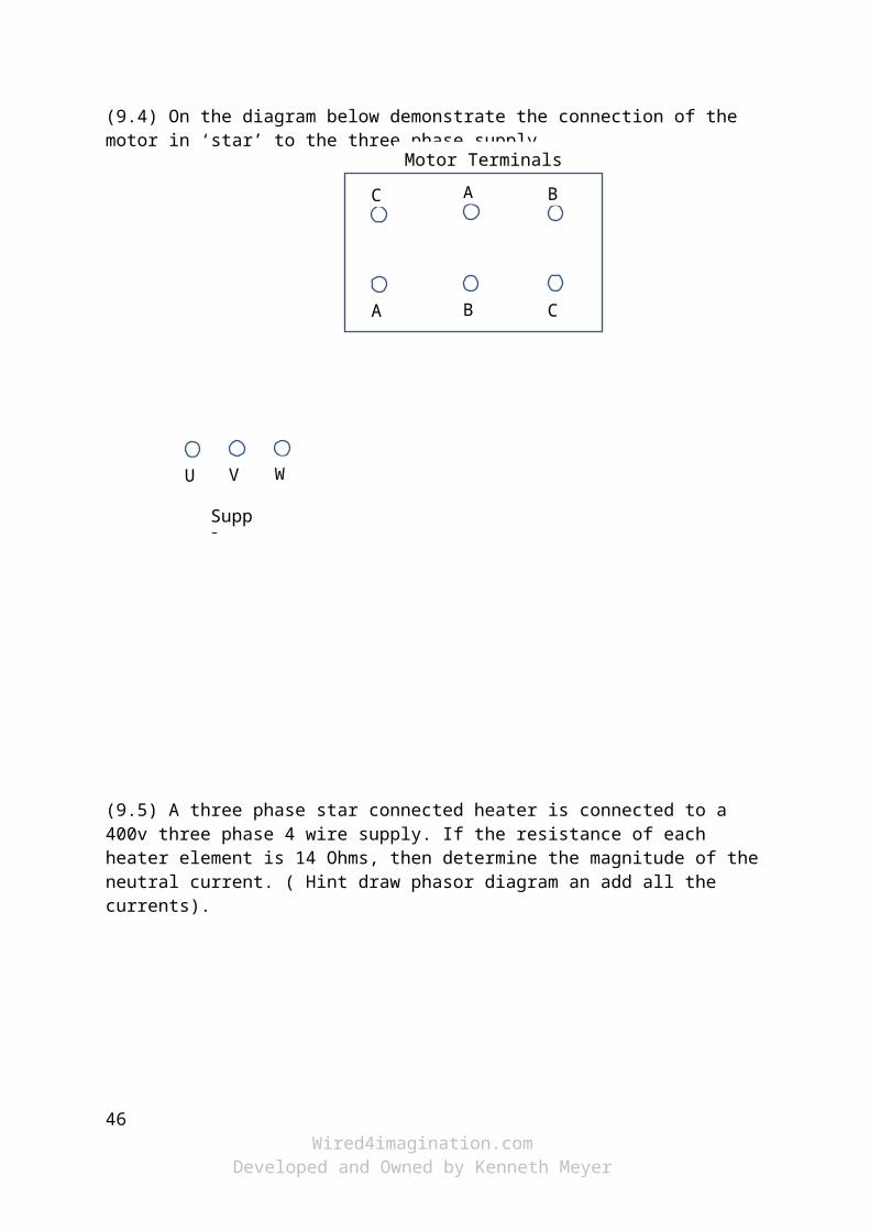
(9.4) On the diagram below demonstrate the connection of the motor in ‘star’ to the three phase supply.
(9.5) A three phase star connected heater is connected to a 400v three phase 4 wire supply. If the resistance of each heater element is 14 Ohms, then determine the magnitude of the neutral current. ( Hint draw phasor diagram an add all the currents).
37Wired4imagination.com
Developed and Owned by Kenneth Meyer
C2 B2A2
A1 B1 C1
U V W
Supply
Motor Terminals
(9.6) A three phase, four wire supply has the following connected;A – Phase to neutral, 4A resistive load.B - Phase to neutral, 3A Lag at 600 C – Phase to neutral, 3A Lead ay 500 Determine the value of the neutral current and direction.
38Wired4imagination.com
Developed and Owned by Kenneth Meyer

(9.7) Three, single phase 240v loads are connected to different phases of a 415 v three phase 4 wires supply. Determine the value and direction of the neutral current if;A Phase - capacitor-run motor taking 11A at 0.91 lead P.F.B Phase – split-phase motor taking 15 A at 0.66 lag P.F.C Phase – 2.4 Kw radiator.
39Wired4imagination.com
Developed and Owned by Kenneth Meyer

40Wired4imagination.com
Developed and Owned by Kenneth Meyer

(9.8) Determine the load star point to neutral voltage of a 400v three phase, four wire system if the following voltages are measured when the neutral is disconnected. A Phase to star point 210v. B Phase to star point is 155V. C Phase to the star point is 270v. (Hint: Draw a 3 phase, “short from”, phasors diagram first to scale.)
41Wired4imagination.com
Developed and Owned by Kenneth Meyer
(9.9) Three 32 heating elements are connected in star to a 415v three phase supply. If the fuse to the line C blows, determine the load phase voltages and the line current for; (a) four-wire system and (b) a three-wire system. ( Draw the circuits!).
42Wired4imagination.com
Developed and Owned by Kenneth Meyer

Blank
43Wired4imagination.com
Developed and Owned by Kenneth Meyer
10. Three phase Delta (Mesh)
(10. 1) A delta connected resistive load takes a current of 28.66 A from the supply. What is the current in each phase?
(10.2) The phase current in each phase of a delta connected load is 150 Amps. What is the current in the supply lines?
(10.3) A delta connected load has phase impedances of 25 Ohms each. The line currents IA = IB and IC = 100A each. ( Draw the circuit).Calculate; (a) the phase currents and (b) the line voltages.
(10.4) A balanced delta connected load consists of a three phase motor with a stator winding impedance of 28 Ohms. Determine the motor line current if the supply is a three phase 440v, 50 Hz.
44Wired4imagination.com
Developed and Owned by Kenneth Meyer
(10.5) A delta connected heater with a 500 W element in each phase is supplied from a three phase, three wire 415 V 50 Hz supply. Determine the current in the heating elements if the fuse in line B has blown. ( Draw it!)
(10.6) An industrial load connected in star has an impedance of 7 Ohms per phase. It is connected to a four wire, there phase 400v supply. (a) calculated the current in each phase of the load. (b) same load now configured in delta. Calculate the new phase current.
45Wired4imagination.com
Developed and Owned by Kenneth Meyer
11. Three phase power
(11.1) A three phase 66kV (line voltage) transformer supplies 800kW balanced three phase load operating at 0.8 P.F. lagging. Determine the line current supplied by the transformer.
(11.2) Calculate the power factor of a system using two wattmeter method if W1= 12 Kw and W2 = 15kW. Also determine the total power consumed by the system.
46Wired4imagination.com
Developed and Owned by Kenneth Meyer

(11.3) A three phase balanced load requires 4 MVA of power when operating at 0.55 lag P. F., connected to an 11kV, 50 Hz three phase supply. Determine (a) the three phase kVAR rating of the capacitance per phase of a start connected capacitor bank that would improve the P.F. to 0.9 lag. (b) the line current before and after the improvement of the power factor.
47Wired4imagination.com
Developed and Owned by Kenneth Meyer
Blank
48Wired4imagination.com
Developed and Owned by Kenneth Meyer

12. Earth Fault Loop Impedance
(12.1) The supply authorities nominated property supply is fault level at 32kA at 230v. Determine the impedance of the supply.
(12.2) The internal impedance of an installations has been determined at 0.0445 Ohms. The supply voltage is 220v. Calculate the fault current.
(12.3) The supply authority has nominate a maximum fault level of 40kA @230v. The internal impedance is measured at 0.245 Ohms. Determine the total earth fault loop impedance.
(12.4) Using as 3008 determine the AC resistance at 50Hz of the following conductor.Conductor is; 6mm2 , Cu, multicore TPS V90, at a length of 174m. Answer in Ohms or Milliohms.
49Wired4imagination.com
Developed and Owned by Kenneth Meyer

Blank
50Wired4imagination.com
Developed and Owned by Kenneth Meyer
Blank
51Wired4imagination.com
Developed and Owned by Kenneth Meyer

13 Dr. Ken’s Assessment techniques. ( Open Textbook )
1. Before an assessment read the textbook, do all the exercises (Practical or Theory) depending on the assessment type.
2. Before the assessment install sticky tabs on the page edges of your textbook to make finding critical aspects easy. Also do the same on AS3000 and AS3008.
3. Take a clean copy of your equation sheet to the assessment. Once assessment starts, make as many notes as you can remember around the formulas. Doing this beforehand is considered cheating.
4. Read through the entire assessment. Note (write down) the easy and hard question numbers. If the equation for a question is obvious, write the question number on the equation sheet next to the relevant equation.
5. Prioritise your time. Three (3) hours and open book may seem as you have plenty of time, but good time management is key. Do easy questions first, then more difficult ones.
6. Answer all the questions, particularly check the multi-choice questions.
7. In maths calculation, try to estimate the size of the answer. If you your calculators answer seem too large or too small, check everything.
8. Answering calculation questions. Put you name and the question number on the working-out sheet. Logically lay-out your answer approach.
(a) Read the question and as you go through, underline the ‘data’(b) Draw / redraw the circuit or diagram and label with the data(c) Decide which part of electrical physics is involved. Eg. Ohms Law, Inductance, etc?(d) Determine the variable that is to be solved for. (e) Select the appropriate formula and write in on the working-out sheet. (f) Insert the data into the formula.(g) Transpose the equation if required to make the missing variable the subject.(h) Solve equation, taking special care with Milli * 10-3 & Mico *10-6 & Kilo *103 etc.(i) Check your answer. Don’t forget Units and angle if any. (j) Underline your final answer/s
9. Review your entire assessment if you have time. Check for missing answers. For questions that have two or more answer are your answers in the correct field?
10. Check again ! This is Competency base assessment. All questions must be correct.
52Wired4imagination.com
Developed and Owned by Kenneth Meyer
Notes: Date:
53Wired4imagination.com
Developed and Owned by Kenneth Meyer
Notes: Date:
54Wired4imagination.com
Developed and Owned by Kenneth Meyer

Notes: Date:
55Wired4imagination.com
Developed and Owned by Kenneth Meyer
Notes: Date:
56Wired4imagination.com
Developed and Owned by Kenneth Meyer