Embed Size (px)
Citation preview

Web-Based Tool for the Automated 3-D Reactive Molding Simulations ROBERT RAJCA, LUKASZ MATYSIAK, MICHAL BANAS, ROBERT SEKULA
ABB Corporate Research
ul. Starowislna 13A, 31-038 Krakow
POLAND [email protected]; [email protected]; [email protected]; [email protected]
http://www.abb.com
Abstract: - This paper presents newly developed 3-D Web-based, user friendly, engineering tool that enables end-users
to start fully 3D reactive molding simulations remotely. The tool that is based on commercial CFD software - Fluent -
enables the simulation of filling and curing stages and gives useful information helping to understand the phenomena
occurring inside the mold.
The elaborated method starts with CAD geometry preparation according to the set of specific rules. Secondly the
geometry is uploaded via the Website. In the next step the Web application analyzes the geometry and detects its
structure automatically. This initial information allows creating a specific Website where, in consequence, engineer
(end-user responsible for the final process and product design) is able to enter process parameters (e.g. velocities,
temperatures, material properties etc.) and start calculations. The meshing and solving stages are performed in fully
automated way. Afterwards the Web application creates the report with simulation results. This report is available via
Website. Based on these information the engineer makes decision to accept the design and process parameters or to
restart the simulation for further optimization.
The presented approach shows main, fully automated, stages including: CAD geometry discretization, solving and
reporting allowing running calculations without or with minimal end-user efforts.
Key-Words: - Reactive molding, CFD simulation, automated meshing, Web-based computations
1 Introduction The fast development of new numerical computing
techniques and availability of highly powerful working
stations make it possible to reduce the time necessary to
design and manufacture final products, at the same time
maintaining their high quality and reliability. Continuing
this trend, numerical computing is more and more often
used for solving design tasks on an industrial scale,
where frequently in the course of implementation of
methods and systems of automated product designing the
designers analyze at the same time the flows of fluids
and the problems of transport of heat and mass within a
designed geometrical model of a product and its mold. In
the case of a process in the reactive molding technology,
in order to better understand the physical phenomena the
knowledge of the structure of very complex 3-
dimentional geometries and the ability to analyze them is
required. Partial differential equations, for example
Navier-Stokes equations, which describe mathematically
and completely fluid movement and heat exchange,
usually are not suitable for an analytic solution, with the
exception of simple cases, because their degree of
complication is too great. Therefore, solution of such
equations on an industrial scale is possible only in a
numerical way using the methods of numerical fluid
mechanics.
Reactive molding is a technology widely used in
processing of epoxy resins, and consists of a number of
process stages, including mold filling, curing with
exothermic reaction, and post-curing. This process of
thermosetting materials is a very good example of
industrial area where advanced computer simulations can
be utilized to design, optimize and visualize products
digitally and evaluate different design concepts before
incurring the cost of physical prototypes. This is a
typical virtual prototyping process that leads, on the one
hand, to cost decrease and on the other hand can provide
useful information about highly complex phenomena
taking place inside the mold during the filling and curing
stages and in addition to detect molding problems prior
to the mold making, such as premature gelation,
undesired weld-line locations and air traps [1,2].
However the existing methods and solutions are
limited to numerically advanced engineers and scientists.
Besides, activities that consist of CAD geometry
preparation and/or simplification, computational
domains discretization and finally solving is time-
consuming.
Additionally nowadays we are facing fast growing
market competitiveness. Time-to-market factor is the
one of the most important and may influence the final
product success in the global market. Therefore
development time of new concepts and products must be
as short as possible.
In currently used solutions [3], all the required design
stages are executed manually by means of autonomous
computer programs which are not directly linked to one
another. Their operation is time-consuming and requires
Proceedings of the 2nd International Conference on Manufacturing Engineering, Quality and Production Systems
ISSN: 1792-4693 194 ISBN: 978-960-474-220-2
the user to possess specialized expertise in many areas
connected with numerical modeling.
That is why it was necessary to develop the new tool
allowing, engineers even not familiarized with CAE
problems, running advanced reactive molding
simulations.
2 Reactive Molding and Modeling
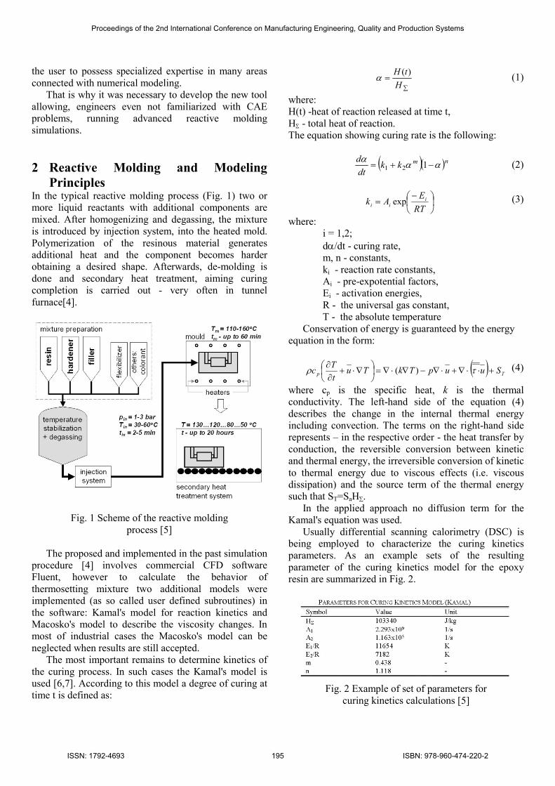
Principles In the typical reactive molding process (Fig. 1) two or
more liquid reactants with additional components are
mixed. After homogenizing and degassing, the mixture
is introduced by injection system, into the heated mold.
Polymerization of the resinous material generates
additional heat and the component becomes harder
obtaining a desired shape. Afterwards, de-molding is
done and secondary heat treatment, aiming curing
completion is carried out - very often in tunnel
furnace[4].
Fig. 1 Scheme of the reactive molding
process [5]
The proposed and implemented in the past simulation
procedure [4] involves commercial CFD software
Fluent, however to calculate the behavior of
thermosetting mixture two additional models were
implemented (as so called user defined subroutines) in
the software: Kamal's model for reaction kinetics and
Macosko's model to describe the viscosity changes. In
most of industrial cases the Macosko's model can be
neglected when results are still accepted.
The most important remains to determine kinetics of
the curing process. In such cases the Kamal's model is
used [6,7]. According to this model a degree of curing at
time t is defined as:
∑
=H
tH )(α (1)
where:
H(t) -heat of reaction released at time t,
HΣ - total heat of reaction.
The equation showing curing rate is the following:
( )( )nmkk
dt
dαα
α−+= 121 (2)
−=
RT
EAk i
ii exp (3)
where:
i = 1,2;
dα/dt - curing rate,
m, n - constants,
ki - reaction rate constants,
Ai - pre-expotential factors,
Ei - activation energies,
R - the universal gas constant,
T - the absolute temperature
Conservation of energy is guaranteed by the energy
equation in the form:
( ) Tp SuupTkTut
Tc +⋅⋅∇+⋅∇−∇⋅∇=
∇⋅+∂∂
τρ )( (4)
where cp is the specific heat, k is the thermal
conductivity. The left-hand side of the equation (4)
describes the change in the internal thermal energy
including convection. The terms on the right-hand side
represents – in the respective order - the heat transfer by
conduction, the reversible conversion between kinetic
and thermal energy, the irreversible conversion of kinetic
to thermal energy due to viscous effects (i.e. viscous
dissipation) and the source term of the thermal energy
such that ST=SaH∑.
In the applied approach no diffusion term for the
Kamal's equation was used.
Usually differential scanning calorimetry (DSC) is
being employed to characterize the curing kinetics
parameters. As an example sets of the resulting
parameter of the curing kinetics model for the epoxy
resin are summarized in Fig. 2.
Fig. 2 Example of set of parameters for
curing kinetics calculations [5]
Proceedings of the 2nd International Conference on Manufacturing Engineering, Quality and Production Systems
ISSN: 1792-4693 195 ISBN: 978-960-474-220-2
Taking into consideration industrial scale of
geometries and in consequence their complexity and in
addition complex physical phenomena taking place
during the described technology process it is expected,
especially by business units, often located far away from
Research & Development or Technical Centers, to
possess an access to automated method for good quality
numerical simulations of reactive molding processes
(CFD mesh generation, CFD computations, reporting).
3 Tool Architecture and Description The developed tool is based on the Web platform (a
number of interacting, developed program applications),
commercial CAD software, commercial Pre-processor
and Processor (both customizable).
START
END
CAD modeling
NO –change process parameters
NO –change design of the product and/or mold
YES
Is process or
product/mold design
correct?
Case creation(Web platform)
Processparametersdefinition
(Web platform)
Model discretization
(Pre-processor)
Computations(Processor)
Analysis of the CAD model
(Web application)
Report generation
(Post-processor)
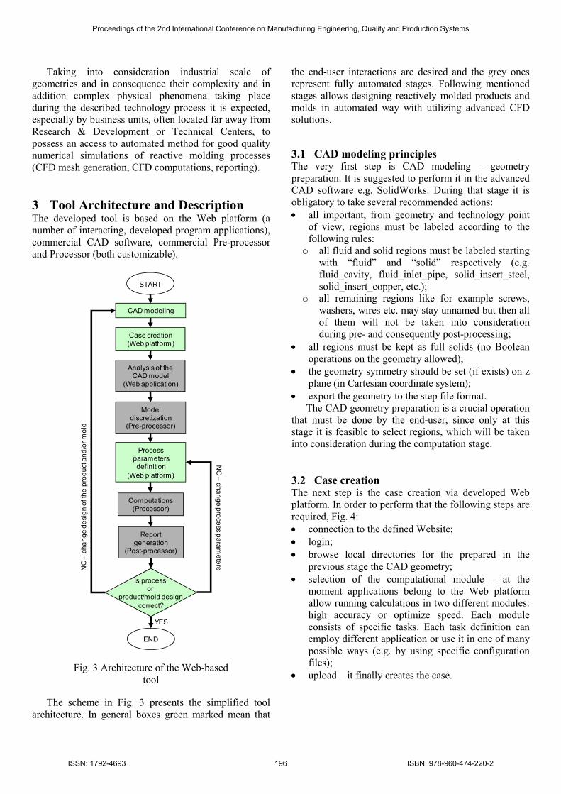
Fig. 3 Architecture of the Web-based
tool
The scheme in Fig. 3 presents the simplified tool
architecture. In general boxes green marked mean that
the end-user interactions are desired and the grey ones
represent fully automated stages. Following mentioned
stages allows designing reactively molded products and
molds in automated way with utilizing advanced CFD
solutions.
3.1 CAD modeling principles The very first step is CAD modeling – geometry
preparation. It is suggested to perform it in the advanced
CAD software e.g. SolidWorks. During that stage it is
obligatory to take several recommended actions:
• all important, from geometry and technology point
of view, regions must be labeled according to the
following rules:
o all fluid and solid regions must be labeled starting
with “fluid” and “solid” respectively (e.g.
fluid_cavity, fluid_inlet_pipe, solid_insert_steel,
solid_insert_copper, etc.);
o all remaining regions like for example screws,
washers, wires etc. may stay unnamed but then all
of them will not be taken into consideration
during pre- and consequently post-processing;
• all regions must be kept as full solids (no Boolean
operations on the geometry allowed);
• the geometry symmetry should be set (if exists) on z
plane (in Cartesian coordinate system);
• export the geometry to the step file format.
The CAD geometry preparation is a crucial operation
that must be done by the end-user, since only at this
stage it is feasible to select regions, which will be taken
into consideration during the computation stage.
3.2 Case creation The next step is the case creation via developed Web
platform. In order to perform that the following steps are
required, Fig. 4:
• connection to the defined Website;
• login;
• browse local directories for the prepared in the
previous stage the CAD geometry;
• selection of the computational module – at the
moment applications belong to the Web platform
allow running calculations in two different modules:
high accuracy or optimize speed. Each module
consists of specific tasks. Each task definition can
employ different application or use it in one of many
possible ways (e.g. by using specific configuration
files);
• upload – it finally creates the case.
Proceedings of the 2nd International Conference on Manufacturing Engineering, Quality and Production Systems
ISSN: 1792-4693 196 ISBN: 978-960-474-220-2

Fig. 4 Case creation page
Geometry of the product and its mold is uploaded via
the Web platform as a file in a well known and widely
used “step” format.
3.3 Analysis of the CAD geometry When the upload is successfully finished the CAD
geometry is automatically (without any further user
interaction) analyzed to detect how many elements
(parts) of each type (e.g. fluid or solid type) it contains.
This stage is extremely important due to the saved data
will be used during the meshing and solving operations.
In addition based on that information the specific Web
page allowing entering process parameters will be
created. The actions defined and performed in that stage
are invisible for the end-user.
3.4 Automated geometry discretization Geometry discretization (mesh generation) is the second
fully automated part of the entire tool. The process of
mesh generation can be explained as geometry
decomposition into finite number of elements – in the
described tool: control volumes. It has long been
considered as a bottleneck in numerical simulations due
to the lack of fully automated mesh generation
procedures.
During the tool development this stage was
recognized as the most challenging part of the job.
Mainly it was related to complex CFD physics
phenomena taking place and significantly different
geometries that might be uploaded by the end-users.
Automated discretization procedure is initiated and
controlled by its own Pre-processor Launcher. The
mentioned automation at the discretization stage is
ensured by the script – a sequence of consecutive
commands, which gives orders to the meshing software
(commercial software named HyperMesh). Thanks to
that the Pre-processor is able to not only recognize and
import the CAD geometry but also perform the
following actions on the geometry:
• cleaning and repairing (removal of holes, fillets,
intersections, overlapping surfaces, etc.);
• discretization of the computational domains in
accordance with the rules stated in the script.
Different regions can be meshed with different
methods. It is possible to obtain both non-structural
and structural mesh;
• set-up of boundary conditions (e.g. inlet, outlet,
convection etc.) based on the specific part names;
• export for the Processor (Fluent) in the “cas” format –
the output file includes discretized, correctly labeled
regions with boundary conditions properly assigned.
Finally, the files generated by the Pre-processor are
stored safely in the process folder and might be used
when the Processor Launcher is free to accept another
task.
It should be stressed here that the Pre-processor is
able to perform all mentioned actions only when the
regions and their names are well defined in the very first
stage – CAD geometry preparation.
a)
b)
Fig. 5 Example of the geometry
complexity (a) and generated mesh (b)
An example of the highly complex geometry that was
tested (was uploaded and computed) with using
developed tool is presented in Fig. 5a. The geometry
consists of typical parts like cavity, mold, insulations,
heater but also includes many inner parts made of
different materials.
The discretized geometry consisted of above 1.5
million of elements of mixed type, Fig. 5b. The whole
automated meshing process of the presented example
takes approximately 45 minutes with using workstation
equipped with 2 x 2.5 GHz cores and 10 MB of RAM.
Proceedings of the 2nd International Conference on Manufacturing Engineering, Quality and Production Systems
ISSN: 1792-4693 197 ISBN: 978-960-474-220-2
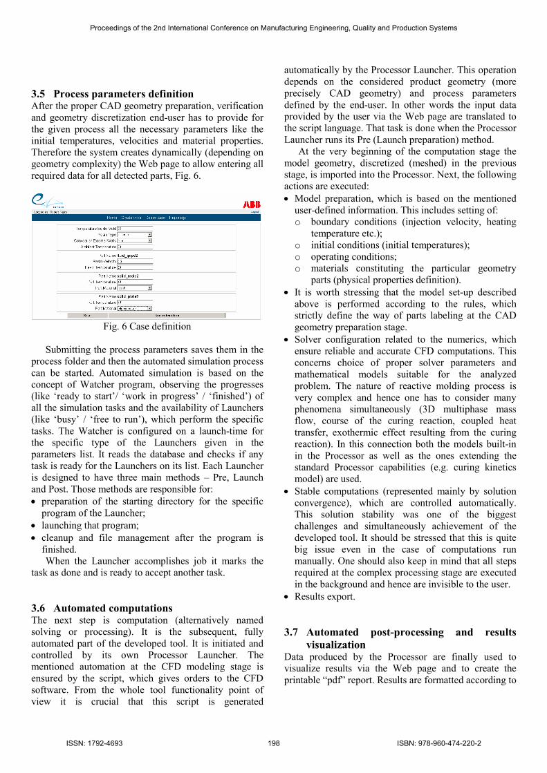
3.5 Process parameters definition After the proper CAD geometry preparation, verification
and geometry discretization end-user has to provide for
the given process all the necessary parameters like the
initial temperatures, velocities and material properties.
Therefore the system creates dynamically (depending on
geometry complexity) the Web page to allow entering all
required data for all detected parts, Fig. 6.
Fig. 6 Case definition
Submitting the process parameters saves them in the
process folder and then the automated simulation process
can be started. Automated simulation is based on the
concept of Watcher program, observing the progresses
(like ‘ready to start’/ ‘work in progress’ / ‘finished’) of
all the simulation tasks and the availability of Launchers
(like ‘busy’ / ‘free to run’), which perform the specific
tasks. The Watcher is configured on a launch-time for
the specific type of the Launchers given in the
parameters list. It reads the database and checks if any
task is ready for the Launchers on its list. Each Launcher
is designed to have three main methods – Pre, Launch
and Post. Those methods are responsible for:
• preparation of the starting directory for the specific
program of the Launcher;
• launching that program;
• cleanup and file management after the program is
finished.
When the Launcher accomplishes job it marks the
task as done and is ready to accept another task.
3.6 Automated computations The next step is computation (alternatively named
solving or processing). It is the subsequent, fully
automated part of the developed tool. It is initiated and
controlled by its own Processor Launcher. The
mentioned automation at the CFD modeling stage is
ensured by the script, which gives orders to the CFD
software. From the whole tool functionality point of
view it is crucial that this script is generated
automatically by the Processor Launcher. This operation
depends on the considered product geometry (more
precisely CAD geometry) and process parameters
defined by the end-user. In other words the input data
provided by the user via the Web page are translated to
the script language. That task is done when the Processor
Launcher runs its Pre (Launch preparation) method.
At the very beginning of the computation stage the
model geometry, discretized (meshed) in the previous
stage, is imported into the Processor. Next, the following
actions are executed:
• Model preparation, which is based on the mentioned
user-defined information. This includes setting of:
o boundary conditions (injection velocity, heating
temperature etc.);
o initial conditions (initial temperatures);
o operating conditions;
o materials constituting the particular geometry
parts (physical properties definition).
• It is worth stressing that the model set-up described
above is performed according to the rules, which
strictly define the way of parts labeling at the CAD
geometry preparation stage.
• Solver configuration related to the numerics, which
ensure reliable and accurate CFD computations. This
concerns choice of proper solver parameters and
mathematical models suitable for the analyzed
problem. The nature of reactive molding process is
very complex and hence one has to consider many
phenomena simultaneously (3D multiphase mass
flow, course of the curing reaction, coupled heat
transfer, exothermic effect resulting from the curing
reaction). In this connection both the models built-in
in the Processor as well as the ones extending the
standard Processor capabilities (e.g. curing kinetics
model) are used.
• Stable computations (represented mainly by solution
convergence), which are controlled automatically.
This solution stability was one of the biggest
challenges and simultaneously achievement of the
developed tool. It should be stressed that this is quite
big issue even in the case of computations run
manually. One should also keep in mind that all steps
required at the complex processing stage are executed
in the background and hence are invisible to the user.
• Results export.
3.7 Automated post-processing and results
visualization Data produced by the Processor are finally used to
visualize results via the Web page and to create the
printable “pdf” report. Results are formatted according to
Proceedings of the 2nd International Conference on Manufacturing Engineering, Quality and Production Systems
ISSN: 1792-4693 198 ISBN: 978-960-474-220-2
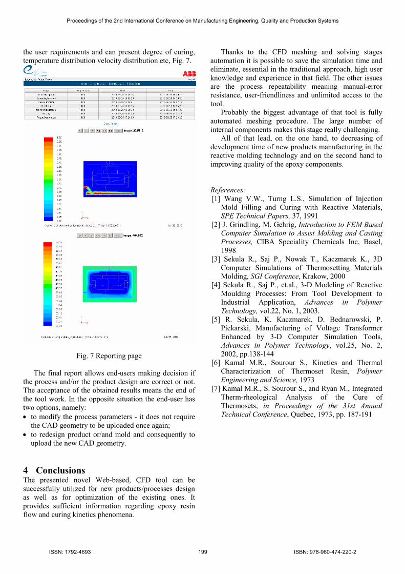
the user requirements and can present degree of curing,
temperature distribution velocity distribution etc, Fig. 7.
Fig. 7 Reporting page
The final report allows end-users making decision if
the process and/or the product design are correct or not.
The acceptance of the obtained results means the end of
the tool work. In the opposite situation the end-user has
two options, namely:
• to modify the process parameters - it does not require
the CAD geometry to be uploaded once again;
• to redesign product or/and mold and consequently to
upload the new CAD geometry.
4 Conclusions The presented novel Web-based, CFD tool can be
successfully utilized for new products/processes design
as well as for optimization of the existing ones. It
provides sufficient information regarding epoxy resin
flow and curing kinetics phenomena.
Thanks to the CFD meshing and solving stages
automation it is possible to save the simulation time and
eliminate, essential in the traditional approach, high user
knowledge and experience in that field. The other issues
are the process repeatability meaning manual-error
resistance, user-friendliness and unlimited access to the
tool.
Probably the biggest advantage of that tool is fully
automated meshing procedure. The large number of
internal components makes this stage really challenging.
All of that lead, on the one hand, to decreasing of
development time of new products manufacturing in the
reactive molding technology and on the second hand to
improving quality of the epoxy components.
References:
[1] Wang V.W., Turng L.S., Simulation of Injection
Mold Filling and Curing with Reactive Materials,
SPE Technical Papers, 37, 1991
[2] J. Grindling, M. Gehrig, Introduction to FEM Based
Computer Simulation to Assist Molding and Casting
Processes, CIBA Speciality Chemicals Inc, Basel,
1998
[3] Sekula R., Saj P., Nowak T., Kaczmarek K., 3D
Computer Simulations of Thermosetting Materials
Molding, SGI Conference, Krakow, 2000
[4] Sekula R., Saj P., et.al., 3-D Modeling of Reactive
Moulding Processes: From Tool Development to
Industrial Application, Advances in Polymer
Technology, vol.22, No. 1, 2003.
[5] R. Sekula, K. Kaczmarek, D. Bednarowski, P.
Piekarski, Manufacturing of Voltage Transformer
Enhanced by 3-D Computer Simulation Tools,
Advances in Polymer Technology, vol.25, No. 2,
2002, pp.138-144
[6] Kamal M.R., Sourour S., Kinetics and Thermal
Characterization of Thermoset Resin, Polymer
Engineering and Science, 1973
[7] Kamal M.R., S. Sourour S., and Ryan M., Integrated
Therm-rheological Analysis of the Cure of
Thermosets, in Proceedings of the 31st Annual
Technical Conference, Quebec, 1973, pp. 187-191
Proceedings of the 2nd International Conference on Manufacturing Engineering, Quality and Production Systems
ISSN: 1792-4693 199 ISBN: 978-960-474-220-2